MAXIMAT TC4
MAXIMAT TC4
MAXIMAT TC4

You also want an ePaper? Increase the reach of your titles
YUMPU automatically turns print PDFs into web optimized ePapers that Google loves.
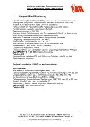
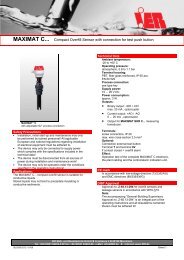
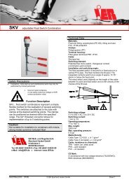
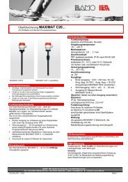
<strong>MAXIMAT</strong> <strong>TC4</strong><br />
Signalling device for up to 4 <strong>MAXIMAT</strong> C series overfill inhibitors / leakage probes<br />
with optical and acoustic signals in accordance with approval requirements for overfill inhibitors (ZG-ÜS)<br />
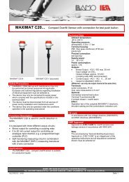
<strong>MAXIMAT</strong> <strong>TC4</strong><br />
Sensor 1<br />
Sensor 2<br />
Sensor 3<br />
Sensor 4<br />
gr ün Betrieb<br />
ge lb Test<br />
rot Alarm<br />
Test<br />
Reset<br />
<strong>MAXIMAT</strong> TC<br />
Safety Precautions<br />
• Installation, initial start-up and maintenance may only<br />
be performed by trained personnel!<br />
• The device must be disconnected from all sources of<br />
power during installation and maintenance work!<br />
• The device may only be operated under the conditions<br />
specified in the operating instructions!<br />
Technical Data<br />
Supply power:<br />
230 V AC or 24 V DC ±20%<br />
Power consumption:<br />
Approx. 6 VA / approx. 6W<br />
Ambient temperature:<br />
-20 to +60° C<br />
Protection per EN 60 529:<br />
IP 65<br />
Special supply power:<br />
15 V DC, short-circuit proof<br />
Inputs:<br />
Up to 4 <strong>MAXIMAT</strong> C series probes<br />
1 external reset contact<br />
Outputs:<br />
4 floating changeover contacts assigned to the individual<br />
probes<br />
1 floating changeover contact for group alarms<br />
1 floating changeover contact for the external horn<br />
Contact rating for output relays:<br />
250 V AC / 115 V DC<br />
500 VA / 3 A<br />
Indicators:<br />
4 LEDs (multicoloured)<br />
Blinking red = alarm pending<br />
Continuous red = alarm acknowledged<br />
Blinking yellow = defective probe<br />
Continuous yellow = test in progress<br />
Continuous green = probe is active<br />
Dark LED = no probe connected<br />
1 piezo signal generator: >75 dB (A)/1m<br />
1 extra-bright flashing LED for group alarm<br />
Controls:<br />
Reset button for acknowledging alarms<br />
Test button for system test<br />
System Test *<br />
• Press the test button.<br />
• The self-test is started for the signalling device.<br />
LEDs light up yellow for probes with test connection.<br />
• Alarm simulation signals are read out to sensors 1, 2, 3<br />
and 4, and the return signals from the sensors are<br />
checked (only for sensors with the test button option).<br />
• The LED indicators, the piezo horn, the group output<br />
relay and the horn output relay are activated.<br />
• Press the buttons located directly on the probes in order<br />
to test the individual probe alarm relays.<br />
Test passed = The respective LED lights up green.<br />
Test failed = The respective LED blinks yellow.<br />
* Note: This function test does not replace the operating test<br />
specified in ZG-ÜS, section 6.2, which must be conducted for all<br />
probes on a regular basis at least once a year.<br />
Wire Breakage Monitoring<br />
Interconnected probes are monitored for broken wires during<br />
operation. Faulty connections are indicated by a blinking<br />
yellow LED for the respective probe. After the error has been<br />
eliminated, the TEST button must be activated, after which<br />
the probe is tested and the LED lights up green once again.<br />
Maintenance<br />
The device is maintenance-free if used for its intended<br />
purpose.<br />
The internal miniature fuse may only be replaced with a<br />
new fuse of identical type!<br />
CE Mark<br />
In accordance with low-voltage directive 73/23/ECC and<br />
EMC directive 89/336/ECC<br />
IER Meß- und Regeltechnik GmbH<br />
Innstrasse 2<br />
D-68199 Mannheim, Germany<br />
Phone: +49 (0)621 84224-0 � Fax: +49 (0)621 84224-90<br />
e-mail: info@IER.de � Internet: www.IER.de<br />
SU0312a.doc 07/06 © IER GmbH Page 1
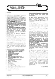
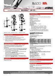
Electrical Connection<br />
sensors<br />
with test<br />
option (T)<br />
only for sensors<br />
<strong>MAXIMAT</strong> C ...,<br />
<strong>MAXIMAT</strong> VK C...<br />
oder<br />
<strong>MAXIMAT</strong> LW C...<br />
external<br />
Reset-<br />
PB<br />
<strong>MAXIMAT</strong> <strong>TC4</strong><br />
do not forget to bridge +AO to +24V !<br />
1<br />
Sensor 2 Sensor 4<br />
+AO<br />
+AO<br />
0V<br />
0V<br />
T -AO +24V (12) T -AO +24V (12)<br />
19 20 21 22 23 24 25 26 27<br />
2 3<br />
4<br />
T -AO +24V 0V<br />
(12)<br />
+AO<br />
5<br />
Sensor 1<br />
6<br />
T<br />
7<br />
8<br />
-AO +24V 0V<br />
(12)<br />
+AO<br />
Sensor 3<br />
9<br />
Alarm 4<br />
NC C<br />
Alarm 2<br />
28 29 30 31 32 33 34 35 36<br />
10 11 12 13 14 15 16 17 18<br />
NC C NO<br />
Alarm 3<br />
NO NC C NO NC C<br />
NC<br />
Alarm 1<br />
Sum-Alarm<br />
C NO NC C<br />
NO<br />
NO<br />
external horn<br />
Signalling Device<br />
<strong>MAXIMAT</strong> TC2<br />
L N<br />
Mains<br />
230V/50Hz<br />
Installation and Initial Start-Up:<br />
• Mount the signalling device to the wall and connect the sensors in accordance with the schematic diagram shown above.<br />
• Connect the signalling device to supply power (230 V AC or 24V DC as specified on the serial plate).<br />
• Switch supply power on.<br />
• The signalling device conducts a self-test (all LEDs and the piezo signal generator are tested).<br />
• Interconnected probes are tested: LEDs light up yellow for probes with test connection.<br />
• Test passed = continuously lit, green LED<br />
• Test failed = blinking yellow LED<br />
• The LEDs for unused channels do not light up at all.<br />
• The following data are entered to a status list by the electronics for later use when the device is switched on for the first time:<br />
- Probe connected to input: yes/no, a single acoustic signal is generated during testing.<br />
- Respective probe equipped with test connection: yes/no, two acoustic signals are generated during testing.<br />
(default setting: no interconnected probes)<br />
• Each time the system test is conducted it can thus be determined whether or not the respective probes function correctly.<br />
• If a new probe is connected, it is added to the status list the next time the device is switched on.<br />
• If an existing probe is disconnected, it is removed from the status list and the respective LED is deactivated: Press and<br />
hold the reset button for at least 5 seconds.<br />
• Attention:<br />
All probes must be tested for correct functioning in accordance with regulations set forth in section 8 of the<br />
general technical approval during initial start-up, and at least once a year thereafter!<br />
Troubleshooting:<br />
None of the LEDs light up and all relays are released, although supply power has been switched on:<br />
• Miniature fuse is blown (on the lower PCB).<br />
• Short-circuit at one ore more probe cables (between 0 V and 24 V). The device is switched off by means of<br />
electronic short-circuit protection, and rapid ticking can be heard from inside the device.<br />
SU0312a.doc 07/06 © IER GmbH Page 2