FIAT 124 Spider Engine Maintenance + Modification - Artigue
FIAT 124 Spider Engine Maintenance + Modification - Artigue
FIAT 124 Spider Engine Maintenance + Modification - Artigue

You also want an ePaper? Increase the reach of your titles
YUMPU automatically turns print PDFs into web optimized ePapers that Google loves.
<strong>Engine</strong> <strong>Maintenance</strong> and <strong>Modification</strong><br />
Bradley <strong>Artigue</strong><br />
1 st Edition
<strong>Engine</strong> <strong>Maintenance</strong> and <strong>Modification</strong><br />
Bradley <strong>Artigue</strong><br />
1 st Edition
Contents<br />
<strong>FIAT</strong> <strong>124</strong> <strong>Spider</strong><br />
<strong>Engine</strong> <strong>Maintenance</strong> + <strong>Modification</strong><br />
1. Introduction ......................................................................................................................................................5<br />
2. Concepts............................................................................................................................................................6<br />
2.1 The Otto Cycle .............................................................................................................................................6<br />
2.2 Lambda ........................................................................................................................................................6<br />
2.3 Carburetor ....................................................................................................................................................7<br />
2.4 Fuel Injection (FI or EFI) ...............................................................................................................................7<br />
2.5 Compression Ratio (CR)...............................................................................................................................7<br />
2.6 Home Mechanic...........................................................................................................................................8<br />
2.7 Shop Manuals and Guides ...........................................................................................................................8<br />
3. <strong>Engine</strong> Identification ........................................................................................................................................9<br />
4. Carburetion .....................................................................................................................................................11<br />
4.1 Understanding Carburetors........................................................................................................................11<br />
4.2 Air Bleed Correction...................................................................................................................................12<br />
4.3 Idle Speed Control .....................................................................................................................................13<br />
4.4 Transition....................................................................................................................................................13<br />
4.5 Acceleration Pump.....................................................................................................................................14<br />
4.6 Cold Starting...............................................................................................................................................15<br />
4.7 Multi-Barrel Synchronization ......................................................................................................................16<br />
4.8 Carburetor Identification and Schematics ..................................................................................................18<br />
4.9 Carburetor Tuning ......................................................................................................................................35<br />
4.10 Diagnostics and Troubleshooting.............................................................................................................36<br />
5. Fuel Injection...................................................................................................................................................38<br />
5.1 Fuel injection Basics ..................................................................................................................................39<br />
5.2 The Air Flow Meter and Fuel Pump ...........................................................................................................40<br />
5.3 Cold Starting Components.........................................................................................................................41<br />
5.4 Warm-Up Components ..............................................................................................................................42<br />
5.5 Idle Speed Control Components................................................................................................................42<br />
5.6 Cruising, Accelerating, and Deceleration Modes .......................................................................................43<br />
5.7 The Oxygen Sensor ...................................................................................................................................44<br />
5.8 Other Components ....................................................................................................................................44<br />
5.9 Component Reference...............................................................................................................................45<br />
5.10 Fuel Injection Tuning................................................................................................................................48<br />
5.11 Fuel Injection System Electrical Diagrams...............................................................................................50<br />
5.12 Fuel Injection System Part Numbers .......................................................................................................53<br />
5.13 Diagnostics and Troubleshooting.............................................................................................................54<br />
6. The Cylinder Head ..........................................................................................................................................59<br />
6.1 Cylinder Head Identification .......................................................................................................................61<br />
7. Intake Manifolds .............................................................................................................................................63<br />
8. Exhaust System..............................................................................................................................................64<br />
8.1 Exhaust System Identification ...................................................................................................................64<br />
9. Ignition ............................................................................................................................................................66<br />
9.1 Ignition Components..................................................................................................................................66<br />
9.2 Ignition System Identification ....................................................................................................................67<br />
9.3 Ignition Advance ........................................................................................................................................68<br />
9.4 Firing Order and Initial Timing ....................................................................................................................69<br />
9.5 Ignition Electrical Diagrams........................................................................................................................72<br />
3
<strong>FIAT</strong> <strong>124</strong> <strong>Spider</strong><br />
<strong>Engine</strong> <strong>Maintenance</strong> + <strong>Modification</strong><br />
9.6 Diagnostics and Troubleshooting...............................................................................................................74<br />
10. The Major Tune Up.......................................................................................................................................76<br />
10.1 Preparation...............................................................................................................................................76<br />
10.2 Tuning Procedure.....................................................................................................................................79<br />
11. Improvements*.............................................................................................................................................80<br />
11.1 Cylinder Head Improvements ..................................................................................................................81<br />
11.2 Intake Manifolds ......................................................................................................................................84<br />
11.3 Ignition .....................................................................................................................................................84<br />
11.4 Exhaust and Emissions Control ...............................................................................................................86<br />
11.5 Carburetors ..............................................................................................................................................87<br />
Figures .................................................................................................................................................................89<br />
Tables ..................................................................................................................................................................90<br />
Copyright © 2007 Bradley James <strong>Artigue</strong>.<br />
All Rights Reserved.<br />
This guide and others in this series are for educational purposes. All are freely distributable in their original,<br />
unedited, and complete form. The online home of this document is www.artigue.com/fiat.<br />
4
1. Introduction<br />
<strong>FIAT</strong> <strong>124</strong> <strong>Spider</strong><br />
<strong>Engine</strong> <strong>Maintenance</strong> + <strong>Modification</strong><br />
Welcome to my guide on <strong>FIAT</strong> <strong>124</strong> <strong>Spider</strong> engine maintenance and modification.<br />
<strong>Spider</strong>s are great cars, born in the mid 1960's when sports cars were fun to drive,<br />
affordable, and easy to work on. They remain a hobbyists’ dream. In 2002 I started to<br />
compile the various pieces of knowledge I obtained over the years into guides, first on<br />
carburetion and intake/exhaust systems, then, in 2004, a guide (more like a pamphlet) on<br />
fuel injection. I revised both guides over the years and finally compiled everything into<br />
this single document. My goal is to help you enjoy your <strong>FIAT</strong> as much as I enjoy mine.<br />
Acknowledgements and great thanks to…<br />
Jennifer <strong>Artigue</strong>, who has always supported (or tolerated) my obsession with<br />
these cars;<br />
Richard Ridge reviewed this guide several times throughout its development and<br />
has been instrumental in reviewing my other works as well;<br />
Eli Caul maintains Mirafiori, the <strong>FIAT</strong> page (www.mirafiori.com) and has worked<br />
tirelessly in his support of the <strong>FIAT</strong> community;<br />
Andrew <strong>Artigue</strong> disassembled, rebuilt, restored, and drove many <strong>Spider</strong>s with<br />
me throughout the last ten or so years;<br />
Troy McKaskle performed the final edits on the document and allowed his cars<br />
to be as test cases long before any of us claimed to know what we were doing;<br />
Pete Angel supplied diagrams and suggestions and reviewed sections of this<br />
document throughout its development;<br />
and Mike Richmond and Thad Kirk who wrote or reviewed sections of my<br />
previous works, much of which was brought over to this document.<br />
Thank you for keeping these cars on the road.<br />
September 2007<br />
5
2. Concepts<br />
<strong>FIAT</strong> <strong>124</strong> <strong>Spider</strong><br />
<strong>Engine</strong> <strong>Maintenance</strong> + <strong>Modification</strong><br />
This section describes some of the basic things we’ll discuss throughout this guide.<br />
2.1 The Otto Cycle<br />
The most common type of operation for automotive engines is the four-stroke cycle, also<br />
known as the Otto cycle. Conceptualized in the 1870's by Nicolaus Otto (and others),<br />
the cycle has four stages of operation, beginning with the engine at Top Dead Center<br />
(TDC), when the piston is furthest from the crankshaft:<br />
• Intake: The intake valve opens and fuel and air are drawn into the engine as the<br />
piston is drawn down.<br />
• Compression: The intake valve is closed and the piston rises, compressing the<br />
mixture.<br />
• Power: The compressed mixture is ignited, the resulting explosion forces the<br />
piston down.<br />
• Exhaust: The exhaust valve opens and the spent gases are forced out as the<br />
piston rises.<br />
If you want to know more about the Otto Cycle theory and all of the mechanical<br />
engineering concepts that are involved pick up a copy of “A Practical Treatise on the<br />
‘Otto’ Cycle Gas <strong>Engine</strong>” by William Norris, Longman, Green, and Co., London, England,<br />
1896. At the time of this writing it is available for download on books.google.com. It is a<br />
very old book but is wonderful at describing the basic concepts of an automobile engine.<br />
2.2 Lambda<br />
Fuel Injection systems and Carburetors have a common goal – to reach an air to fuel ratio<br />
of 14.7:1 and maintain that ratio through changing engine loads. The ratio is known as<br />
the stoichiometric air-fuel ratio for gasoline. It is commonly referred to as lambda. Any<br />
mixture less than 14.7:1 is considered rich; any mixture above is considered lean.<br />
The air fuel mixture is established on a carburetor by setting mechanical devices, such as<br />
air bleeders, fuel jets, and emulsion tubes. On a fuel injection system the mixture is<br />
constantly adjusted by a computer that varies the amount of fuel sprayed into the<br />
cylinder. Both systems rely on a stream of measured air, regulated by a throttle, to<br />
deliver atomized fuel into the engine.<br />
6
2.3 Carburetor<br />
<strong>FIAT</strong> <strong>124</strong> <strong>Spider</strong><br />
<strong>Engine</strong> <strong>Maintenance</strong> + <strong>Modification</strong><br />
A carburetor is a device that mixes fuel and air together for use in an internal combustion<br />
engine. A throttle regulates the amount of airflow into an engine and the subsequent<br />
increase in air speed and drop in pressure. A restriction in the carburetor barrel, known<br />
as a venturi, forces the air stream to increase in speed as it passes by a number of fueldelivering<br />
orifices. The orifices enrich the stream of air with fuel. The resulting mixture<br />
is a near lambda combination of air and fuel.<br />
2.4 Fuel Injection (FI or EFI)<br />
A fuel injection system delivers a metered amount of fuel under high pressure into a<br />
stream of air. Unlike carburetion, fuel injection does not rely on the pumping of the<br />
engine to draw fuel into the air stream. Instead the fuel is forced through a small orifice<br />
(a fuel injector) at very high pressure. The flexibility of fuel injection systems and<br />
accuracy of fuel delivery leads to increased horsepower, better atomization of fuel,<br />
reduction in emissions, and improved fuel economy.<br />
2.5 Compression Ratio (CR)<br />
The compression ratio is used to measure the performance of an internal combustion<br />
engine. The compression ratio is calculated by taking the cylinder bore (diameter), piston<br />
stroke, and volume of the combustion chamber prior to ignition. The formula looks like<br />
this:<br />
Where b is cylinder bore diameter, s is the piston stroke length, and Vc is the volume of<br />
the combustion chamber. It is important to note that your author inserted this only to<br />
demonstrate use of the pi (π) character and because formulas make guides like this one<br />
look more scientific and authoritative.<br />
<strong>FIAT</strong> <strong>Spider</strong>s had compression ratios that ranged from a low of 7.5:1 (<strong>Spider</strong> Volumex) to<br />
a high of 9.8:1 (<strong>124</strong> Sport <strong>Spider</strong> 1608). The Volumex relied on a supercharger to<br />
increase the horsepower of the engine; therefore, it is notable that compression ratios<br />
alone are not the sole indication of an engine’s capabilities. Generally speaking, and<br />
since most of us would not install (and could not find) a Volumex supercharger on our<br />
<strong>FIAT</strong>, mild increases in CR towards the 9.8:1 range result in good performance<br />
increases. CR is typically increased with a piston swap, although other methods<br />
(described later in this guide) will bump it up a point or two.<br />
Pistons are available that will drive the CR of the engines upwards, all the way to 11:1. A<br />
general rule about compression ratios is that the higher the CR the higher octane fuel<br />
7
<strong>FIAT</strong> <strong>124</strong> <strong>Spider</strong><br />
<strong>Engine</strong> <strong>Maintenance</strong> + <strong>Modification</strong><br />
you will need to keep the engine from knocking. These days most <strong>FIAT</strong>s are recreational<br />
vehicles, and pump-grade ‘super’ unleaded of 92 or higher octane will satisfy the CR of<br />
any stock <strong>Spider</strong> up to 9.8:1.<br />
2.6 Home Mechanic<br />
Throughout this guide I make references to the “home mechanic.” This is, most likely,<br />
you. As these cars age finding a qualified professional mechanic is becoming more and<br />
more difficult. <strong>Spider</strong>s are easy to work on and, with few exceptions, will not require<br />
any specialized tools to make run correctly. Your best source for diagnostics is yourself;<br />
if you must use a professional mechanic arm yourself with the ability to discuss the<br />
problem.<br />
2.7 Shop Manuals and Guides<br />
A “shop manual” is referred to many times in this guide. There is only one shop manual<br />
for your car, it was originally published by <strong>FIAT</strong> and is sold by <strong>FIAT</strong> parts vendors. There<br />
were also numerous “guides” published by companies like Autobook, Haynes, Chilton’s,<br />
and Drake. To avoid any confusion please note that unless explicitly stated, references<br />
to the shop manual always indicate the <strong>FIAT</strong> shop manual.<br />
8
3. <strong>Engine</strong> Identification<br />
<strong>FIAT</strong> <strong>124</strong> <strong>Spider</strong><br />
<strong>Engine</strong> <strong>Maintenance</strong> + <strong>Modification</strong><br />
It is important to know what engine, cylinder head, carburetor, intake manifold, and<br />
exhaust system you have on your <strong>FIAT</strong>. Understanding what you have allows you to<br />
make an educated decision about what you need. If you are not 100% sure of what you<br />
have then take a few moments to check - many have had engine, cylinder head,<br />
carburetor, exhaust, ignitions, and all kinds of other parts swapped out. You need to<br />
know what you’re running in order to get it running right or swap it for the right thing.<br />
The engine identification number is stamped into the engine block near the oil filter. It is<br />
sometimes covered in grime. Carburetor cleaner or degreaser and a brush will allow you<br />
to read it. On the <strong>Spider</strong> 2000 engine (1979-1985) it is located just to the right of the oil<br />
filter. On all <strong>Spider</strong>s manufactured prior to 1979 it is located above the oil filter. Check<br />
your engine number with the chart on the next page. It is important to note that the last<br />
few numbers may not match up - this usually indicates an engine swap at some point in<br />
your car’s history. If the first digits (i.e. 132A1 is always a 1756) are correct then you<br />
have the original displacement engine in your vehicle. If the last few digits (i.e. 031.5)<br />
are correct then you have the original displacement and model year type.<br />
Figure 1: <strong>Engine</strong> Identification<br />
What if you don’t have the original engine? This situation is more common than you<br />
might think – many owners installed larger motors to gain additional performance, a<br />
common swap was the 1608cc for the 1438cc. Others had swaps due to necessity,<br />
such as installing a 1978 engine in their 1975 because the original no longer worked.<br />
Whether or not a swap was good is something you need to decide for yourself; if<br />
originality is your goal then it may be worthwhile to seek out the original parts. If power<br />
is more important then it might be worth keeping that 102 HP 1608cc instead of<br />
installing a 91 HP 1438cc.<br />
9
Table 1: <strong>Engine</strong> Identification Table<br />
<strong>FIAT</strong> <strong>124</strong> <strong>Spider</strong><br />
<strong>Engine</strong> <strong>Maintenance</strong> + <strong>Modification</strong><br />
Model Year Series From S/N <strong>Engine</strong> Displacement<br />
1967 – 1969 <strong>124</strong>AS 5619 <strong>124</strong>AC.040 1438cc<br />
1970 – 1971 <strong>124</strong>BS 21861 <strong>124</strong>AC.040 1438cc<br />
1971 - 1972 <strong>124</strong>BS1 33950 125BC.040 1608cc<br />
1973 <strong>124</strong>CS 59592 125BC.040 1608cc<br />
1973 <strong>124</strong>CS 63308 132AC.040.3 1592cc<br />
1974 <strong>124</strong>CS1 71650 132A1.040.4 1756cc<br />
1975 <strong>124</strong>CS1 88792 132A1.040.5 1756cc<br />
1975 <strong>124</strong>CS1 132A1.031.5 1756cc<br />
1976 <strong>124</strong>CS1 99909 132A1.040.5 1756cc<br />
1976 <strong>124</strong>CS1 132A1.031.5 1756cc<br />
1977 <strong>124</strong>CS1 113343 132A1.040.5 1756cc<br />
1978 <strong>124</strong>CS1 132A1.031.5 1756cc<br />
1978 <strong>124</strong>CS1 126001 132A1.040.5 1756cc<br />
1978 <strong>124</strong>CS1 132A1.031.5 1756cc<br />
1979 <strong>124</strong>CS2 142514 132C2.040 1995cc<br />
1980 <strong>124</strong>CS2 132C2.031 1995cc<br />
1980 <strong>124</strong>CS2 157654 132C3.040 1995cc<br />
1981 – 1985* <strong>124</strong>CS0 171001 132C3.031 1995cc<br />
* Pininfarina Sold the <strong>124</strong> as the “Azzura” and “<strong>Spider</strong>europa” after 1982<br />
10
4. Carburetion<br />
<strong>FIAT</strong> <strong>124</strong> <strong>Spider</strong><br />
<strong>Engine</strong> <strong>Maintenance</strong> + <strong>Modification</strong><br />
<strong>FIAT</strong> <strong>Spider</strong>s manufactured from 1967 through 1980 were equipped with carburetors,<br />
except in California where the 1980 model year introduced fuel injection. Carburetors<br />
were provided by Weber SpA (Italy). <strong>FIAT</strong> and Weber have a long history; in the 1920s<br />
Eduardo Weber began producing carburetors for conversion kits intended for <strong>FIAT</strong><br />
vehicles. His designs were the first progressive twin-barrel types with one barrel smaller<br />
than the other. Various updraft, downdraft, and sidedraft designs were produced by<br />
Weber and the carburetors were installed on vehicles ranging from small engine street<br />
cars to twelve cylinder racing cars. Weber carburetors are still used today in off-road,<br />
racing, and street applications.<br />
4.1 Understanding Carburetors<br />
An easy way to understand how a carburetor works is to study a very simple type, the<br />
single-barrel, updraft carburetor. After this brief introduction we’ll work through<br />
subsequent improvements to arrive at carburetors similar to the one on your <strong>FIAT</strong>.<br />
C<br />
E<br />
D<br />
F<br />
Figure 2: Updraft Carburetor. A Float Chamber Vent , B Fuel Bowl or Chamber, with Float , C Spray Tube,<br />
D Fuel Jet , E Venturi , F Throttle<br />
Referring to figure 2, an updraft carburetor has the following features:<br />
• A fuel bowl or chamber (A) in which a float-controlled needle valve keeps the<br />
fuel constantly at a level 5-6mm lower than the fuel in jet (D).<br />
A<br />
B<br />
11
<strong>FIAT</strong> <strong>124</strong> <strong>Spider</strong><br />
<strong>Engine</strong> <strong>Maintenance</strong> + <strong>Modification</strong><br />
• A Venturi (E). The purpose of the venturi is to increase the depression acting on<br />
jet (D) to favor the vaporization of the gasoline sprayed from the jet during<br />
engine operation.<br />
• A spray tube or nozzle (C) through which fuel flows from float chamber to<br />
calibrated jet (D).<br />
• A throttle (F) that regulates the amount of fuel/air mixture drawn in by the<br />
engine.<br />
Updraft carburetors were understandably impractical. Carburetors quickly progressed to<br />
down draft types, with an important improvement known as air bleed correction.<br />
4.2 Air Bleed Correction<br />
Emulsion tubes mixed air with the fuel prior before entering the carburetor. This air<br />
bleed correction (figure 3) made operation more efficient.<br />
Figure 3: Air Bleed Correction. A Float Chamber Vent , B Fuel Bowl or Chamber, with Float , C Spray<br />
Tube, D Fuel Jet , E Venturi , F Throttle , G Air bleed jet, H Well for emulsion tube, I Emulsion Tube<br />
A perforated emulsion tube (I) enables air and fuel to be mixed prior to being sprayed<br />
into the carburetor barrel. This results in fuel “misting” into the barrel. The arrangement<br />
allows for larger jets and supply tubes and a wider range of tuning. Air enters the<br />
emulsion tube through an air bleed correction jet. The jet is removable, allowing for<br />
precise adjustment of how much air is allowed into the emulsion tube well. There is one<br />
well, emulsion tube, and jet per carburetor barrel.<br />
12
4.3 Idle Speed Control<br />
<strong>FIAT</strong> <strong>124</strong> <strong>Spider</strong><br />
<strong>Engine</strong> <strong>Maintenance</strong> + <strong>Modification</strong><br />
An additional improvement is an idle speed device (figure 4). This device allows your<br />
engine to maintain the lowest rpm rate at which it will keep running.<br />
4<br />
T<br />
2 1 3<br />
Figure 4: Idle Speed Circuit. D main fuel jet, Da idle speed air jet, Db idle speed fuel jet, 1 idle speed<br />
mixture orifice, 2 transition device, 3 idle speed mixture adjusting screw, 4 throttle setting or idle speed<br />
adjusting screw<br />
The throttle is nearly closed and fuel is drawn from below the throttle plate, rather than<br />
from the main jetting. The idle speed device is an independent circuit on the carburetor,<br />
sharing the fuel bowl with the main circuit but having its own mixture setting, jetting,<br />
and an idle speed screw to regulate throttle position and engine speed.<br />
4.4 Transition<br />
We’ve reviewed the main and idle stages of a carburetor, so let’s take a look at how your<br />
carburetor transitions smoothly from the idle stage to the main stage. In the side of your<br />
carburetor barrel are holes, known as progression holes or transition orifices. Movement<br />
of the throttle past these holes draws fuel into the engine (specifically, a drop in pressure<br />
draws fuel through the holes as the throttle passes), creating additional speed while<br />
building up to the main stage.<br />
Da<br />
Db<br />
D<br />
13
D<br />
Idle Transition Main<br />
2<br />
1<br />
<strong>FIAT</strong> <strong>124</strong> <strong>Spider</strong><br />
<strong>Engine</strong> <strong>Maintenance</strong> + <strong>Modification</strong><br />
Figure 5: Transition Stage. 1 idle mixture orifice, 2 transition orifice, C spray nozzle, E venturi, F throttle<br />
As the throttle continues to move the idle circuit, fuel feed to the progression holes will<br />
cut off, and the engine will run entirely on the main circuit. Figure 5 depicts a carburetor<br />
with a single transition orifice; in reality your carburetor may have several to make a<br />
smooth transition. Without these holes the engine would stutter between the idle and<br />
main stages.<br />
Holes in the side of the carburetor are not enough to keep the transition and power<br />
curves smooth. Your <strong>FIAT</strong> <strong>Spider</strong> has a “quick throttle,” meaning that throttle<br />
movements can be fast enough to cause a lean condition. To compensate for this your<br />
carburetor is fitted with an accelerator pump, used to inject additional fuel during the<br />
transition stage.<br />
4.5 Acceleration Pump<br />
<strong>FIAT</strong>s use a diaphragm-type accelerating pump, as depicted in figure 6. A roller under<br />
the throttle mechanicals rests on a plate. When the throttle is moved the plate turns<br />
against the roller, causing an arm to press the diaphragm in and force fuel through the<br />
pump jet and into the stream of air passing through the carburetor. This richens the<br />
mixture of fuel to compensate for the lean condition caused during quick throttle<br />
movement.<br />
C<br />
E<br />
14
F<br />
L K<br />
4<br />
5<br />
M<br />
3<br />
1<br />
<strong>FIAT</strong> <strong>124</strong> <strong>Spider</strong><br />
<strong>Engine</strong> <strong>Maintenance</strong> + <strong>Modification</strong><br />
Figure 6: Diaphragm-type accelerating pump – 1 Control lever, 2 Pump spring, 3 diaphragm return spring,<br />
4 Cam lever, 5 Roller, F Throttle, J inlet valve, K Delivery valve, L Pump jet, M pump drain jet, N Pump<br />
diaphragm<br />
4.6 Cold Starting<br />
On a cold morning your <strong>FIAT</strong> may be hard to start. If things are working properly you will<br />
do one of three things to set the cold start device. You may pull a knob under your<br />
dashboard. This knob is connected to a cable that moves a metal plate over the top of<br />
your carburetor. If you have a later model <strong>FIAT</strong> (specifically those fitted with the ADHA<br />
or ADFA carburetor) you might press the accelerator to the floor before starting the car<br />
and then release it. This sets a semi-automatic, water-controlled mechanism in place.<br />
This mechanism moves a metal plate over the top of your carburetor as well. Finally,<br />
you might do nothing, meaning that you have an electric choke on a non-standard<br />
carburetor. In case you’re wondering the electric choke also moves a metal plate over<br />
the top of the carburetor. In all types this metal plate “chokes” the carburetor,<br />
restricting the amount of air entering the engine but having no effect on the amount of<br />
fuel. This causes a very rich condition, conducive to cold starting.<br />
In figure 7 a simple choke is depicted. A plate moves upward, restricting airflow into the<br />
barrel but not fuel. Once engine operating temperature is reached the choke is disabled<br />
and normal airflow returns. Improvements in chokes over the years made them more<br />
convenient and efficient. An automatic choke will vary the position of the restricting<br />
plate as engine temperature increases, until the choke plate is fully open at normal<br />
operating temperature. Weber refers to this as an “anti-flooding device” as flooding an<br />
engine will occur if a choke is left fully “on” during normal temperatures.<br />
J<br />
N<br />
2<br />
15
C<br />
F<br />
E<br />
Engaged Disengaged<br />
O<br />
P<br />
<strong>FIAT</strong> <strong>124</strong> <strong>Spider</strong><br />
<strong>Engine</strong> <strong>Maintenance</strong> + <strong>Modification</strong><br />
Figure 7: Offset choke, P choke valve, C spray nozzle, E venturi, F throttle, O calibrated spring<br />
4.7 Multi-Barrel Synchronization<br />
We now move into the final discussion on carburetor operation, the multi-barrel<br />
carburetor. Multi-barrel - in our case dual barrel - carburetors were designed to solve<br />
several problems. Efficient fuel delivery into a four cylinder engine is difficult with one<br />
single barrel carburetor. Fitting multiple single barrel carburetors, such as one per<br />
cylinder or one per two cylinders would achieve good efficiency but introduce complex<br />
(and expensive) throttle assemblies, complicate the fuel line plumbing, etc.<br />
A dual-barrel carburetor provides for sharing of common components, such as the fuel<br />
bowl and throttle mechanicals. There is also a single idle circuit in a dual-barrel<br />
carburetor, simplifying tuning and making low-speed operation (such as driving in city<br />
streets) more efficient. Dual-barrel carburetors work through the synchronization of the<br />
throttle plates in each barrel.<br />
16
<strong>FIAT</strong> <strong>124</strong> <strong>Spider</strong><br />
<strong>Engine</strong> <strong>Maintenance</strong> + <strong>Modification</strong><br />
Figure 8: Mechanically controlled differential opening of the throttles. F1 Primary throttle, F2 Secondary<br />
throttle, Q Accelerator level integral with primary throttle F1, R Intermediate lever for control of secondary<br />
throttle F2<br />
The synchronization is established through a mechanical or vacuum linkage that activates<br />
the secondary barrel when the primary barrel is approximately 2/3 open.<br />
In figure 8, our carburetor starts with the throttles at rest. A throttle arm (A) rotates the<br />
primary throttle (F1), bringing the carburetor through idle and progression phases. An<br />
intermediate lever (L) is activated at a mechanically set point, connecting the primary and<br />
secondary (F2) throttles. As the main throttle reaches wide open throttle the secondary<br />
is also fully open, with both barrels running on their main circuits.<br />
A vacuum carburetor (figure 9) achieves the same goal in a different manner. Instead of<br />
a lever in between the main and secondary throttles, a diaphragm is connected to the<br />
secondary barrel. When a sufficient pressure drop is reached in the primary barrel the<br />
secondary barrel begins to open. Progression of the secondary throttle is always<br />
controlled by the pressure drop in the primary barrel, making the vacuum carburetor<br />
somewhat less “snappy” than the mechanical type.<br />
17
<strong>FIAT</strong> <strong>124</strong> <strong>Spider</strong><br />
<strong>Engine</strong> <strong>Maintenance</strong> + <strong>Modification</strong><br />
Figure 9: Vacuum controlled differential opening of the throttles – 1 Interconnection between primary<br />
venturi E and diaphragm S, E Venturi, F1 Primary throttle, F2 Secondary throttle, S Diaphragm for<br />
operation of secondary throttle F2, Q accelerator level integral with primary throttle F1 –R intermediate<br />
level for control of secondary throttle F2 activated by the movement of diaphragm T integral to vacuum<br />
operated spring mechanism S<br />
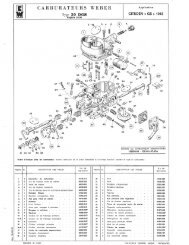
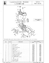
4.8 Carburetor Identification and Schematics<br />
Weber stamped an identification number on your carburetor body. Depending on the<br />
construction of the carburetor body, this number may be between the middle and lower<br />
halves of the carburetor, or on the lowest mounting flange on the “front” (facing the<br />
fender) or “back” (facing the cylinder head) side. It may in a different location altogether<br />
but should be fairly easy to spot. The number may be quite long, but the primary<br />
information is in the first few positions. Figure 10 shows the base of a 1970 Weber<br />
26/34 DHSA1.<br />
18
Figure 10: DHSA1 Carburetor Base Plate<br />
<strong>FIAT</strong> <strong>124</strong> <strong>Spider</strong><br />
<strong>Engine</strong> <strong>Maintenance</strong> + <strong>Modification</strong><br />
Weber nomenclature is not easy to decipher. The important thing to note is the<br />
numbers before the letters and the letters themselves. If you read “26/34 DHSA 1 OC”<br />
then you can simply note that you have a “26/34 DHSA”. The numbers following the<br />
letters indicate things like barrel size, factory jetting, emissions control modifications,<br />
etc. The variations are minor but almost impossible to track. Using the chart below,<br />
note whether or not your carburetor was original equipment on your engine:<br />
Table 2: Carburetor Identification<br />
Vehicle Year Displacement Carburetor<br />
<strong>124</strong> <strong>Spider</strong> 66-67 1438 34 DFH<br />
<strong>124</strong> <strong>Spider</strong> 68-69 1438 26/34 DHSA1<br />
<strong>124</strong> <strong>Spider</strong> 70-71 1438 26/34 DHSA1<br />
<strong>124</strong> Sport <strong>Spider</strong> 71-73 1608 28/36 DHSA2 or 3<br />
<strong>124</strong> Sport <strong>Spider</strong> 71-73 1608 Dual 40 IDF<br />
<strong>124</strong> Sport <strong>Spider</strong> 73 1592 28/36 DHSA2 or 3<br />
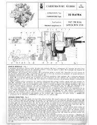
<strong>124</strong> <strong>Spider</strong> 1756 74 1756 34 DMSA<br />
<strong>124</strong> <strong>Spider</strong> 1756 75-76 1756 32 ADFA<br />
<strong>124</strong> <strong>Spider</strong> 1756 77-78 1756 32 ADFA<br />
<strong>Spider</strong> 2000 79-80 1995 28/32 ADHA<br />
19
<strong>FIAT</strong> <strong>124</strong> <strong>Spider</strong><br />
<strong>Engine</strong> <strong>Maintenance</strong> + <strong>Modification</strong><br />
4.8.1 Weber DFH<br />
The DFH was used on early production 1438cc <strong>Spider</strong>s. It is not a common item on cars<br />
imported into the United States. The DFH is operationally similar to the DHSA carburetor<br />
fitted on later models.<br />
4.8.2 Weber DHSA<br />
The DHSA was used on the 1438 and 1608 motors. Vehicles imported into the United<br />
States received the 26/34 DHSA1 and the 28/36 DHSA2. The numbers refer to the<br />
primary (26 or 28) and secondary (34 and 36) barrel sizes.<br />
Figure 11: DHSA2 Carburetor<br />
The DHSA is a progressive two-barrel carburetor with a vacuum operated secondary.<br />
This secondary throttle opens when the primary throttle is fully open. This opening is<br />
controlled by a diaphragm mounted on the side of the carburetor and linked to the<br />
secondary throttle shaft (refer to figure 9 in the previous section). The different DHSA<br />
models are directly interchangeable with each other and with the DMS and DMSA<br />
carburetors.<br />
The DHSA has a mechanically operated choke, meaning that a cable connects the choke<br />
plate to a knob. The driver pulls the knob, activating the plate, and restricting airflow into<br />
the carburetor.<br />
There are two additional small diaphragms that are electrically activated by the position<br />
of the clutch. These devices are also attached to fast idle speed controller, electronically<br />
linked to the clutch assembly and to a switch on the transmission. When you shift into<br />
or out of 3 rd , 4 th , and 5 th gears the controller keeps the engine speed around 1500 RPM.<br />
The actual speed at which the controller engages is set by a switch in the engine<br />
compartment.<br />
20
<strong>FIAT</strong> <strong>124</strong> <strong>Spider</strong><br />
<strong>Engine</strong> <strong>Maintenance</strong> + <strong>Modification</strong><br />
The diagrams on the following pages show the exploded views of the DHSA carburetor.<br />
For a description of the operation of the carburetor refer to the section on the DMSA.<br />
The DMSA is operationally similar with the exception of the vacuum secondary.<br />
Figure 12: DHSA External Parts, Float Mechanisms, and Choke Assembly<br />
Figure 13: DHSA Jetting, Throttle Mechanisms, and Internal Parts<br />
21
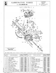
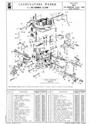
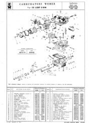
4.8.3 Weber IDF<br />
<strong>FIAT</strong> <strong>124</strong> <strong>Spider</strong><br />
<strong>Engine</strong> <strong>Maintenance</strong> + <strong>Modification</strong><br />
European 1608 Sport <strong>Spider</strong>s produced from 1971 until 1973 were fitted with dual<br />
Weber 40 IDF carburetors. Although never an option for U.S. cars many of the manifolds<br />
and carburetor pairs were installed on <strong>Spider</strong>s of virtually every engine displacement<br />
from 1608 to 2000. Although no <strong>FIAT</strong> manifold directly fit the 1438 series, an Abarth<br />
manifold was produced that would allow for IDFs on that engine.<br />
The <strong>FIAT</strong> Abarth <strong>Spider</strong> CSA (1972), a rare factory produced street version of an Abarth<br />
race car, was also fitted with dual IDFs. The actual racing version had dual 44 IDFs<br />
carburetors or mechanical fuel injection.<br />
Figure 14: IDF Carburetor Side View<br />
Through needle valve (6) fuel passes into bowl (2) where float (3), hinged on pivot pin (1),<br />
controls needle (5) stroke to keep the fuel level constant. Needle (5) is connected to the<br />
lug of float (3) via return latch (4).<br />
Figure 15: IDF Normal Operation<br />
22
<strong>FIAT</strong> <strong>124</strong> <strong>Spider</strong><br />
<strong>Engine</strong> <strong>Maintenance</strong> + <strong>Modification</strong><br />
From bowl (2), through main jets (18), fuel reaches wells (17). After mixing with the air<br />
from emulsion tubes (16) and air corrector jets (9), the fuel reaches the carburetion area<br />
consisting of auxiliary venturis (11) and main venturis (12) via nozzle (10). The carburetors<br />
incorporate a mixture enriching device whose principle of operation is as follows: Fuel is<br />
drawn from bowl (2) through calibrated holes in tubes (8) and into the carburetor through<br />
spray tubes (7) during high speed operation.<br />
The illustration shows also the crankcase emission control system — diagrams A and B<br />
—. The crankcase emission control system consists of a rotary blanking disc (22) driven<br />
by spindle shaft (14) controlled by lever (13). Through slot (21) the blanking disc connects<br />
blow-by gas tube (19) with the downstream side of butterfly valves (15). Even with<br />
butterflies (15) in idling speed position gas suction is controlled by calibrated hole (20).<br />
Figure 16: IDF Progression<br />
From wells (17) fuel passes to idle jets (24) via ducts (25). Emulsified with the air coming<br />
from calibrated bushes (23) through ducts (26) and bushes (28), adjustable by means of<br />
screws (27), the mixture reaches carburetor ducts on downstream side of butterflies<br />
(15).<br />
Bushes (28) are calibrated to control idling speed output.<br />
Starting from idle condition, when butterflies (15) are progressively opened the mixture<br />
reaches the carburetor ducts via progression holes (32) to bring about an increase in<br />
engine angular velocity. To obtain a consistent air feed in both carburetor ducts with<br />
butterflies (15) in idle position, a variable volume of air from ducts (30), depending on the<br />
position of screws (31), is fed to the downstream side of butterflies (15) through holes<br />
(29) situated in alignment with adjusting screws (31).<br />
23
Figure 17: IDF Acceleration<br />
<strong>FIAT</strong> <strong>124</strong> <strong>Spider</strong><br />
<strong>Engine</strong> <strong>Maintenance</strong> + <strong>Modification</strong><br />
Upon closing butterflies (15) lever (37) frees diaphragm (41) which, under the pressure of<br />
spring (40), draws fuel from bowl (2) through ball valve (38).<br />
Upon opening butterflies (15) diaphragm (41) under the action of cam (36) and lever (37)<br />
injects fuel into carburetor ducts through ways (35), delivery valves (33) and pump jet<br />
nozzles (34). Spring (39) dampens any sudden butterfly opening and prolongs fuel<br />
delivery.<br />
The excess fuel delivered by the accelerating pump is exhausted into bowl (2) together<br />
with the pump chamber vapours, through calibrated bush (42).<br />
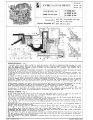
Figure 18: IDF Cold Start Devices<br />
From bowl (2) fuel passes to the starting device through ducts (44) and starting jets (43).<br />
Emulsified with the air from holes (50), fuel reaches the recess of valves (49) through<br />
ducts (45) and holes (46). Then, completely emulsified with the air drawn from holes<br />
24
<strong>FIAT</strong> <strong>124</strong> <strong>Spider</strong><br />
<strong>Engine</strong> <strong>Maintenance</strong> + <strong>Modification</strong><br />
(48), the mixture is conveyed to carburetor ducts on downstream side of butterflies (15)<br />
via ducts (47).<br />
Starting with a cold engine - Starting device ON - position A.<br />
Starting with a semi-warm engine - Starting device partially ON - Position B.<br />
<strong>Engine</strong> warm-up - During this stage, even with the vehicle in motion, disengage the<br />
starting device gradually.<br />
Normal operation - Starting device OFF - Position C to be restored as soon as the engine<br />
reaches normal operating temperature.<br />
4.8.4 Weber DMSA<br />
Figure 19: IDF Dimensions<br />
The DMSA was used for a single year (1974). It is virtually identical to a DHSA except it<br />
lacks the vacuum operated secondary. DMSA has a mechanically-operated secondary<br />
and the largest primary and secondary throttles of any carburetor installed on the<br />
<strong>Spider</strong>s. The advantage over the DHSA is there is no time lag during heavy acceleration<br />
for manifold pressure to pull open the secondary. The DMSA is a slightly larger<br />
carburetor than the DHSA2; this was to accommodate for the larger 1756cc engine<br />
introduced in 1974.<br />
25
Figure 20: DMS Carburetor Side View<br />
<strong>FIAT</strong> <strong>124</strong> <strong>Spider</strong><br />
<strong>Engine</strong> <strong>Maintenance</strong> + <strong>Modification</strong><br />
The DMSA and DMS are popular upgrades for DHSA owners. Problems with the<br />
vacuum-operated secondary unit (typically stemming from a misunderstanding of how it<br />
works) would lead to cars that ran poorly. The DMS, with a direct mechanical<br />
connection between the throttle plates, eliminated these problems. As DHSA<br />
carburetors wore out they were often replaced with brand new DMS units.<br />
Figure 21: DMS Normal Operation<br />
Through needle valve (1) fuel passes into bowl (17) where the float (18) hinged on pivot<br />
pin (20) sets the needle (2) opening to keep level constant: the needle (2) is connected to<br />
float tab (18) via return hook (19). From bowl (17) through main jets (16) fuel reaches<br />
well (15). After mixing with the air from orifices of emulsion tubes (14) and air corrector<br />
jets (5), through nozzles (9) fuel reaches the carburetion area consisting of auxiliary<br />
venturis (10) and main venturis (11). This carburetor is provided with a mixture-enriching<br />
26
<strong>FIAT</strong> <strong>124</strong> <strong>Spider</strong><br />
<strong>Engine</strong> <strong>Maintenance</strong> + <strong>Modification</strong><br />
device on the primary (34 DMS/201) or secondary barrel (34 DMS 1/201 - 34 DMS<br />
2/201): from bowl (17) the fuel metered by a calibrated bush (3) get mixed with the air<br />
coming from calibrated orifice (4).<br />
The mixture thus formed through duct (6) and calibrated bush (7) is drawn via duct (8) -<br />
into the carburetor primary or secondary barrel during high speed running.<br />
The figure also shows the device for differentiated opening of throttle valves. Upon<br />
actuating throttles control lever (25) the tab (26) of the lever plate (22) fixed on primary<br />
shaft (12) turns and the primary throttle (13) opens by an equivalent angle whilst the<br />
secondary throttle (24) on spindle (23) remains closed.<br />
Subsequently, tab (26) contacts the lug (27) of idle lever (21) which, by shifting the lever<br />
(28), rotates the secondary spindle (23) until both throttles are simultaneously wide open.<br />
The figure above also shows the device for gases aspiration from engine crankcase -<br />
schemes A and B. It consists of a rotary blanking disc (31) driven by primary shaft (12)<br />
which through groove (32) connects the tube (29) - conveying gases to be aspirated -<br />
with the area downstream of primary throttle (13). Even with throttles in idle position,<br />
conveyance of aspirated gases still takes place and is metered by the calibrated orifice<br />
(30).<br />
Figure 22: DMS Progression<br />
27
<strong>FIAT</strong> <strong>124</strong> <strong>Spider</strong><br />
<strong>Engine</strong> <strong>Maintenance</strong> + <strong>Modification</strong><br />
From emulsion tube (15) the fuel is drawn to idle jet (48) through duct (42): emulsified<br />
with the air from calibrated bush (49) via duct (46) it get mixed with the air from<br />
calibrated orifice (47) and reaches the carburetor primary barrel downstream of throttle<br />
(13) through the calibrated bush (37) adjustable by screw (41).<br />
Mixture reaches the primary barrel also from duct (45) through calibrated hole (44) where<br />
it is further emulsified with the air entering from hole (43) and conveyed downstream of<br />
throttle (13) via the hole (38) adjustable by screw (40) - (by-pass idling).<br />
Starting from idle rate and gradually opening throttle (13) mixture flows to primary barrel<br />
also from progression holes (39) thus allowing a smooth increase in engine angular<br />
speed.<br />
When opening the secondary throttle (24), the fuel coming from secondary emulsion<br />
tube passes to idle jet (34) through the duct (35): emulsified with the air from calibrated<br />
bush (33) via duct (36) it flows to secondary barrel through progression holes (50) placed<br />
at throttle (24) level which allow a steady increase in engine angular speed.<br />
Figure 23: DMS Acceleration<br />
Upon closing throttles, the lever (58) frees diaphragm (57) which through action of the<br />
spring (55) draws fuel from the bowl (17) through ball valve (54). Upon opening throttles<br />
by means of cam (59) lever (60) and lever (58), the diaphragm (57) injects fuel in<br />
carburetor primary barrel via duct (61), delivery valve (51) and pump jet (52). Spring (56)<br />
absorbs quick opening of throttles and extends fuel delivery stage. Any excess fuel<br />
28
<strong>FIAT</strong> <strong>124</strong> <strong>Spider</strong><br />
<strong>Engine</strong> <strong>Maintenance</strong> + <strong>Modification</strong><br />
delivered by the accelerator pump is exhausted into bowl (17) along with pump chamber<br />
vapors, through the calibrated bush (53).<br />
Figure 24: DMS Starting<br />
With lever (63) in position A >, butterflies (62) blank the carburetor air intakes whilst<br />
throttle (13) opens partially by mean of rod (67) and lever (68) fast idle.<br />
Thus nozzle (10) delivers a rich mixture allowing prompt engine starting.<br />
Once engine is started, the vacuum acting on butterflies (62) and the action of diaphragm<br />
(66) open butterflies (62) partially against action of spring (64).<br />
In these conditions the mixture, still rich, allows normal engine running.<br />
Once engine has reached the rated temperature, disengage the device completely -<br />
position B “: butterflies (62) are kept wide open by the lug (65) whilst primary throttle<br />
(13) is brought to idle position. <strong>Engine</strong> starting - engage starting device by pulling knob<br />
completely out - position A<br />
<strong>Engine</strong> warm-up - during engine warm-up, even with vehicle running, disengage the<br />
device progressively. Normal running - device off - position B as soon as engine operates<br />
smoothly at rated temperature.<br />
29
Figure 25: DMS Dimensions<br />
<strong>FIAT</strong> <strong>124</strong> <strong>Spider</strong><br />
<strong>Engine</strong> <strong>Maintenance</strong> + <strong>Modification</strong><br />
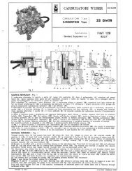
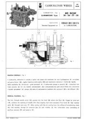
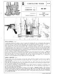
4.8.5 Weber ADFA<br />
The ADFA was introduced in the 1975 model year and used through the 1978 model<br />
year. It has a mechanically-controlled secondary and a choke that is controlled by water<br />
temperature. This choke is semi-automatic; to activate it the gas pedal is pressed to the<br />
floor. If the engine is cold this will release a spring-loaded toothed wheel that holds the<br />
choke in place. There is no other manual action required; as engine water temperature<br />
increases the spring expands, acting upon the toothed wheel and closing the choke in<br />
stages.<br />
Figure 26: ADF Carburetor Side View<br />
30
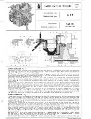
Figure 27: ADF Normal Operation<br />
<strong>FIAT</strong> <strong>124</strong> <strong>Spider</strong><br />
<strong>Engine</strong> <strong>Maintenance</strong> + <strong>Modification</strong><br />
Through needle valve (1), fuel passes into bowl (16) where the float (17), hinged on pivot<br />
pin (19) sets the opening of needle (20) in order to keep fuel level constant: the needle<br />
(20) is connected to the lug of float (17) through the return hook (18). The fuel, from bowl<br />
(16) reaches wells (14) through main jets (15). After mixing with the air coming from<br />
orifices of emulsion tubes (13) end from air corrector jets (6), the fuel reaches, vie<br />
nozzles (8), the carburetion area consisting of auxiliary venturis (7) end venturis (9).<br />
The carburetor is provided with the enrichment circuit on second barrel: from bowl (16),<br />
the fuel, through duct (10) end calibrated bush (2), blends with the air coming from<br />
calibrated orifices (3). The mixture thus formed will be sucked — through duct (4) end<br />
calibrated pipe (5) — by the second barrel during full power operation at high r.p.m.<br />
Fig. 1 also shows the device for differentiated opening of throttle valve. Acting on<br />
throttles control lever (25), this will first travel a given idle distance: primary throttle (23)<br />
— fitted on spindle (24) — will open of a corresponding angle, while secondary throttle<br />
(12) — fitted on spindle (11) — remains in closed position. Successively, lever (25)<br />
contacts free lever (22), which by shifting lever (21) makes the secondary spindle (11)<br />
rotate until contemporary end complete opening of both throttles is reached.<br />
Also shown in Fig. I is the control system for crankcase emission — diagrams A and B.<br />
— This consists of a rotary blanking disc (29) driven by shaft (24) controlled by lever (25)<br />
which, by means of groove (26) — diagrams A and B — connects pipe (28) conveying<br />
gases to be sucked, with the area downstream of throttle (23).<br />
Even by throttle (23) in idle position — diagram A — goes on conveyance of sucked<br />
gases metered by calibrated orifice (27).<br />
31
Figure 28: ADF Idle Speed and Progression<br />
<strong>FIAT</strong> <strong>124</strong> <strong>Spider</strong><br />
<strong>Engine</strong> <strong>Maintenance</strong> + <strong>Modification</strong><br />
From primary well (30) fuel reaches idle jet (34) through duct (43): after emulsifying with<br />
the air coming from calibrated bush (35), it flows through duct (42), calibrated bush (40)<br />
— adjustable by screw (41) — and reaches the primary throat downstream of throttle<br />
(23). The mixture reaches the primary duct also through progression holes (44) near the<br />
primary throttle; this allows a smooth increase in engine angular velocity starting from<br />
idle running.<br />
By opening of secondary throttle (12), the fuel coming from the secondary well flows to<br />
idle jet (36) through duct (38); after emulsifying with the air coming from calibrated bush<br />
(37), it reaches, via duct (39), the secondary throat through progression holes (45).<br />
Figure 29: ADF Acceleration<br />
32
<strong>FIAT</strong> <strong>124</strong> <strong>Spider</strong><br />
<strong>Engine</strong> <strong>Maintenance</strong> + <strong>Modification</strong><br />
Upon opening of throttles, the diaphragm (50), under the action of cam (53) and lever<br />
(52), injects fuel into primary carburetor throat through duct (54), delivery valve (55) and<br />
nozzle (46).<br />
Spring (51) absorbs quick throttle opening and allows regular feeding from jet (46). Any<br />
excess fuel delivered by accelerating pump, together with pump chamber vapors, is<br />
exhausted into bowl (16) through calibrated orifice (48). Upon closing throttles, lever (52)<br />
sets free the diaphragm (50) which draws in fuel from bowl (16) through ball valve (47),<br />
under the action of spring (49).<br />
Figure 30: ADF Starting<br />
The choke is of semi-automatic type: this means that to insert it when engine is cold, it<br />
is necessary to depress the accelerator pedal completely, then to release it slowly to<br />
normal position.<br />
Once the starting device is inserted, the bimetallic coil (68) — via lever (67), spindle (56),<br />
lever (57) and rod (58) — keeps the choke plate (59) closed. At the same time, the cam<br />
lever (60) will be in the position as shown in Fig. 4 and, by means of lever (25) —<br />
adjustable by screw (61) — it will keep the primary throttle (23) partially open (fast idling).<br />
In these conditions, the nozzle (8) delivers a given amount of mixture which, diluted with<br />
the air controlled by starter plate gape, allows a quick starting of the engine.<br />
After starting, the vacuum set up beneath throttle (23) through duct (64), acts on<br />
diaphragm (65) which being displaced by rod (66) and bush (62) the latter held by the<br />
spring (62) make the lever (67) rotate against the action as the bimetallic coil (68) which,<br />
via spindle (56), lever (57) end rod (58), will partially open the starter plate (59) thus<br />
supplying a mixture strength suitable to allow a normal engine running.<br />
33
<strong>FIAT</strong> <strong>124</strong> <strong>Spider</strong><br />
<strong>Engine</strong> <strong>Maintenance</strong> + <strong>Modification</strong><br />
Should the accelerator be depressed when the choke is included, the screw (61) would<br />
disengage the cam (60) which drawn by spring (63) would reduce the opening of primary<br />
throttle (23).<br />
The engine cooling-water warms up, and, circulating in the cover (70) heats the bimetallic<br />
coil (58) which will make the lever (67) turn and through the above mentioned linkage<br />
system, will cause the progressive opening of choke plate (59). During rotation of<br />
primary throttle (23), the cam lever (60) will also rotate thus excluding progressively the<br />
choke.<br />
Once running temperature is reached, the choke plate (59) will be in fully open position:<br />
the screw (61) is now no longer in contact with the cam (60) thus allowing primary<br />
throttle (23) to close up till to normal idling position.<br />
Figure 31: ADF Anti-Pollution Device<br />
ADF type carburetors, provided with vacuum devices to reduce air pollution, are fitted on<br />
cars equipped with electric switches that set off a special electro valve located between<br />
intake manifold and fuel inlet pipe (74).<br />
The vacuum, through pipe (74), acts on diaphragm (73) which, by means of rod (72),<br />
lever (71) and lever (53), opens primary throttle (23) to fast idle position: adjustment of<br />
throttle (23) opening is carried out through adjusting screw (75).<br />
Under such opening conditions, during motoring over, exhaust emission levels are rather<br />
low; within the air pollution tolerances. When vacuum is intercepted by the electro valve,<br />
the air sucked through duct (76), nullifies vacuum acting on diaphragm (73) and allows<br />
throttle (23) to return to normal idling position.<br />
34
Figure 32: ADF Dimensions<br />
<strong>FIAT</strong> <strong>124</strong> <strong>Spider</strong><br />
<strong>Engine</strong> <strong>Maintenance</strong> + <strong>Modification</strong><br />
4.8.6 Weber ADHA<br />
The ADHA is similar to the ADFA except for the secondary barrel, which is vacuum<br />
controlled. This is a hard carburetor to love. Introduced with the 2000cc engine the<br />
ADHA was a small carburetor on the largest of the <strong>Spider</strong> motors. Although a carburetor<br />
with 23mm and 32mm barrels should be adequate for a 2 liter motor, the jetting, intake<br />
manifold, and array of pollution control devices both on and off of the carburetor resulted<br />
in a fairly uninspiring driving experience.<br />
4.9 Carburetor Tuning<br />
These are the recommended procedures per Weber with some modifications, you will<br />
find the same general steps in any publication on setting up carburetors. Should the<br />
engine fan come on during these steps STOP working (leave the engine running) until it<br />
shuts off. Fans draw current from the alternator, creating a load that will reduce engine<br />
speed and may cause you to make incorrect adjustments. Fans are also dangerous to<br />
work around.<br />
4.9.1 Set Carburetor to Factory Settings<br />
Back out the idle speed screw until it is no longer in contact with the throttle stop lever.<br />
Now turn the screw until it contacts the lever and again 1 ½ turns.<br />
Turn the idle mixture screw (on our carburetors it is typically in the center bottom of the<br />
carburetor body) in until it is fully seated - do not force the screw. Now turn it back out<br />
two full turns.<br />
4.9.2 Start and warm the <strong>Engine</strong><br />
Disengage or block the choke open. On automatic chokes you can use a small clamp or<br />
wire to pull the choke mechanism open. The engine should start and run poorly (if it<br />
35
<strong>FIAT</strong> <strong>124</strong> <strong>Spider</strong><br />
<strong>Engine</strong> <strong>Maintenance</strong> + <strong>Modification</strong><br />
does not remain running then increase the idle speed screw ½ turn until it does). Adjust<br />
the idle speed screw until the engine runs at approximately 900 RPM.<br />
Let the engine warm up to operational temperature. On a <strong>Spider</strong> you will typically wait<br />
until the fan has cycled two times (on-off-on-off). Turn the mixture screw in (lean the<br />
mixture). If the engine increases in speed then continue to turn until it is no longer<br />
increasing or runs worse, then back the screw out ½ turn. If the engine decreases in<br />
speed then turn the screw out until it is increasing in speed. Continue to turn until it is<br />
no longer increasing or runs worse, then turn the screw in ½ turn. Adjust the idle to<br />
approximately 850 RPM.<br />
4.9.3 Final Settings<br />
Set the idle speed screw so that the engine runs at 850 RPM, or 900 RPM if you have air<br />
conditioning. Recheck the mixture screw by turning slightly in then out. <strong>Engine</strong> speed<br />
should be set - using the mixture screw ONLY - to the fastest and smoothest point of<br />
operation (listen for exhaust popping). Reset the idle speed screw as necessary.<br />
Drive the car under various loads (idle, cruise, hard acceleration, gradual acceleration,<br />
etc.) for a short period of time then remove one of the spark plugs. The electrode should<br />
be brownish-white in color. A white plug results from an engine that is too lean; a black<br />
plug from one that is too rich. Adjust the mixture screw slightly to compensate.<br />
4.10 Diagnostics and Troubleshooting<br />
4.10.1 Air Input Diagnostics<br />
The only source of air entering the engine should be through the carburetor barrels. Air<br />
entering the engine through a broken gasket or carburetor spacer can cause poor<br />
running. You can spray carburetor cleaner around the base of the carburetor; there<br />
should be no change in engine speed. Also check the tightness of the bolts holding the<br />
carburetor to the manifold, they should be tight (but not so tight you’re bending the base<br />
plate!).<br />
If you find that air is entering around the throttle assembly then you might have throttle<br />
rods and bushings that have worn themselves out. The carburetor will need to be rebuilt<br />
or replaced. Also inspect the carburetor body for any cracks or leaking fuel. Cracks can<br />
let in air and typically require the carburetor to be replaced.<br />
4.10.2 Mixture Problems<br />
If problems appear to be stemming from the fuel mixture there are a few areas to<br />
diagnose, all of which deal with the basic air/fuel mixture settings on the carburetor.<br />
Always too lean<br />
If the vehicle runs too lean, even with the mixture screw “all the way out” (meaning to<br />
the limit of reasonable travel, or about 4-5 turns) then you may have idling jets that are<br />
36
<strong>FIAT</strong> <strong>124</strong> <strong>Spider</strong><br />
<strong>Engine</strong> <strong>Maintenance</strong> + <strong>Modification</strong><br />
too small. Consider increasing the idle jet size by adding 10 to the size (if you had a 45,<br />
increase to 55) then re-set the mixture. Continue up (or down) in increments of 5 or 10 if<br />
this appears to be helping.<br />
Always too rich or very limited adjustment range<br />
If the vehicle runs too rich, even with the mixture screw “all the way in” (seated) then<br />
you may have idling jets that are too large. Consider decreasing the idle jet size by<br />
subtracting 10 from the size (if you had a 55, increase to 45) then re-set the mixture.<br />
Continue down (or up) in increments of 5 or 10 if this appears to be helping. Also apply<br />
this procedure if your mixture is correct by barely moving the mixture screw open as this<br />
will limit your ability to tune the mixture.<br />
Idles with mixture screw seated<br />
If your carburetor idles with the mixture screw fully seated then the car is idling on the<br />
main throttle and not on the idle jets. Reset your throttle linkage by using the procedure<br />
described in the tune-up section. If this fails to solve the problem then observe your<br />
carburetor spraying fuel during operation and look for leaks. The accelerator pump may<br />
be leaking into the main barrel during idle operation, causing enough fuel to mix (and mix<br />
poorly) to maintain idle.<br />
Poor transition / flat spots in acceleration<br />
During acceleration the transition between the idle, progression, and wide-open stages<br />
should be smooth. If not then your secondary idle jet, main jet, or secondary jet may be<br />
too small, causing a lean condition in between stages. If you are running a stock<br />
carburetor on a reasonably stock engine then check that the jets meet or in the same<br />
basic range as was stock for your model year.<br />
Puffing and mild backfires<br />
The mixture can cause puffing and mild backfires at or outside of the idle stage. If you<br />
are having these issues then open the mixture screw 1/8 turn and note any change. This<br />
will slightly richen the mixture and may eliminate these lean conditions. Continue in 1/8<br />
increments until you’ve reached a full turn, if there is no difference then reset and check<br />
the timing, adjusting as necessary.<br />
37
5. Fuel Injection<br />
<strong>FIAT</strong> <strong>124</strong> <strong>Spider</strong><br />
<strong>Engine</strong> <strong>Maintenance</strong> + <strong>Modification</strong><br />
<strong>FIAT</strong> <strong>Spider</strong>s manufactured from 1967 through 1978 were equipped with carburetors.<br />
Vehicles manufactured from the 1980 model year through the end of production in 1985<br />
were equipped with electronic fuel injection. There is some argument about the<br />
transition from carburetion to fuel injection. The most plausible story is that <strong>FIAT</strong> first<br />
offered fuel injection as an option, then as standard equipment in California, then as<br />
standard equipment for the entire line. Regardless of when or why you can always tell<br />
what system your vehicle had installed by looking at the body style number. This is the<br />
first four or five positions in your vehicle’s VIN number. The VIN is stamped in your<br />
engine compartment, on a small metal plate on your dashboard (near the driver’s side<br />
windshield), and on some models inside the driver’s side door. The first three positions<br />
will read “<strong>124</strong>” or (on later vehicles) “ZFA<strong>124</strong>”, followed by a two letter “primary” body<br />
code.<br />
AS, BS, CS1, CS2: Carburetion<br />
CS0, DS: Fuel Injection<br />
VX: Carburetion / Supercharger<br />
Fuel injection systems were provided by Bosch GmbH (“Bosch”). Carburetion and fuel<br />
injection approach mixing fuel and air in very different ways. Simply put, a carburetor<br />
mixes fuel outside of the combustion chamber. The mixture is drawn through a plenum<br />
into the combustion chamber. In a carburetor the settings that govern the mixture of<br />
fuel and air remain relatively static, fixed mechanically by the jets and orifices in the<br />
carburetor and when the vehicle is tuned. A fuel injection system sprays metered fuel<br />
directly into the manifold at the intake port during the intake cycle. The Bosch system<br />
used in a <strong>FIAT</strong> electronically controls the amount of fuel, resulting in more dynamic<br />
control of air to fuel ratios.<br />
By the end of the 1970’s fuel injection systems were slowly overtaking carburetion on<br />
the drawing boards of automotive engineers. Driven by emissions control regulations<br />
and a noticeable improvement in performance and fuel economy, fuel injection was<br />
evolving from complex mechanical systems to electronic “engine management”<br />
systems. The Bosch L-Jetronic system was used on the majority of European fuel<br />
injected cars, including <strong>FIAT</strong>, Alfa Romeo, Ferrari, Lamborghini, Lancia, BMW, Mercedes,<br />
Porsche, Renault, Volkswagen, and Peugeot. It was preceded by a number of<br />
mechanical systems, including the K-Jetronic by Bosch and mechanical systems by<br />
38
<strong>FIAT</strong> <strong>124</strong> <strong>Spider</strong><br />
<strong>Engine</strong> <strong>Maintenance</strong> + <strong>Modification</strong><br />
SPICA, Kugelfischer, and others. Unlike its predecessors, L-Jetronic had an electronic<br />
brain controlling the injector pulse and numerous sensors telling the brain what the fuel<br />
system was doing. It is superseded by Bosch Motronic. Unlike Motronic, L-Jetronic is<br />
not as tightly integrated with the engine; one could consider L-Jetronic a “bolt-on” fuel<br />
injection system where Motronic is more “engineered in” to the engine design.<br />
Bosch has always been a leader in fuel injection worldwide because of its association<br />
with Mercedes and their leadership with diesel and aircraft engine design. Bosch began<br />
developing electronic fuel injection in the 1950s and licensed some early American<br />
designs as well. Bosch introduced electronic control to its production fuel injection<br />
designs in 1974. A more sophisticated and reliable system, the L-Jetronic soon<br />
emerged. An oxygen sensor followed and was quickly adopted by European car makers<br />
including <strong>FIAT</strong> who were struggling to make small high performance engines meet the<br />
1980 California and 1981 U.S. Federal emissions requirements.<br />
5.1 Fuel injection Basics<br />
Figure 33: Bosch L-Jetronic Fuel Injection as used in the <strong>FIAT</strong> <strong>Spider</strong> 2000.<br />
39
<strong>FIAT</strong> <strong>124</strong> <strong>Spider</strong><br />
<strong>Engine</strong> <strong>Maintenance</strong> + <strong>Modification</strong><br />
The <strong>FIAT</strong> implementation of the Bosch L-Jetronic fuel injection system is relatively<br />
simple and uses the most basic components required to operate the system. Many<br />
additional options including atmospheric pressure sensors, knock sensors, and crank<br />
angle sensors, are all possibilities with L-Jetronic but were never installed. <strong>FIAT</strong> quite<br />
literally built a system around the existing 2000cc carbureted engine. The simplicity<br />
results in a system that is inexpensive, easy to diagnose, and can be repaired by the<br />
home mechanic. The system consists of a number of components that are located in<br />
the engine and passenger compartments. Figure 33 summarizes the major components<br />
and some of their connections.<br />
5.2 The Air Flow Meter and Fuel Pump<br />
The air flow meter is positioned just above the air filter and is the only point of entry for<br />
air into the fuel injection system. Inside is a spring-tensioned flap connected to a<br />
rheostat. As intake air volume increases the flap moves an arm against the rheostat.<br />
The rheostat converts the movement of the flap into an electrical current that is sent to<br />
the fuel injection computer and is the primary input in the system. Fuel is delivered in<br />
proportion to the volume of air and the fuel injection computer adjusts the fuel delivery<br />
to best find the 14.7:1 air to fuel ratio.<br />
The stream of new air passes through the main air hose (also called the “big air hose”),<br />
connecting to the throttle body. The operation is abbreviated as follows:<br />
1. Air passes the throttle plate into the plenum (the square aluminum box on the<br />
engine intake side) and is drawn through runners (pipes under the plenum) into<br />
the engine.<br />
2. The fuel injection computer opens the injectors and sprays fuel into the intake<br />
runners (the four tubes between the plenum and the cylinder head). All four<br />
injectors fire at the same time.<br />
3. Valves open and draw the mixture into the combustion chamber.<br />
4. The mixture is compressed and explodes via ignition spark.<br />
5. The mixture is expelled.<br />
6. An oxygen sensor measures the amount of unburned oxygen in the exhaust.<br />
7. The F.I. computer uses the reading from the oxygen sensor to adjust the next<br />
mixture.<br />
40
<strong>FIAT</strong> <strong>124</strong> <strong>Spider</strong><br />
<strong>Engine</strong> <strong>Maintenance</strong> + <strong>Modification</strong><br />
The air flow meter also activates the fuel pump. Unlike the 3-5psi pumps of carbureted<br />
engines, fuel injection pumps must produce the high pressure that forces fuel into a mist<br />
while passing through the injector bodies. The pump fitted to the <strong>FIAT</strong> 2000 engine<br />
produces between 50 and 80psi, which is controlled to between 36 and 43psi by the fuel<br />
pressure regulator. As air passes through the air flow meter a chrome rod closes a<br />
circuit that activates the fuel pump. So long as air is passing through the meter the<br />
pump will run; once the vehicle stops drawing air the pump will shut off.<br />
5.3 Cold Starting Components<br />
Let’s discuss the fuel injection components that are used during cold-starting of an<br />
engine. When a cold engine is started it requires substantially more fuel than a warm<br />
engine. This is due to condensation of the fuel in the air/fuel mixture. A device called a<br />
thermo-time switch (see Figure 34) is located directly under the <strong>Spider</strong> intake manifold.<br />
This switch determines the length of time the cold start valve, remains on. The cold<br />
start valve is a fifth injector, inserted into the side of the plenum. This injector sprays<br />
fuel directly into the air entering the plenum. This rich mixture remains until the engine<br />
reaches a temperature sufficient to eliminate condensation of fuel and keep the engine<br />
running. This process takes from 2 to 8 seconds depending on the coolant temperature.<br />
Figure 34: Cold Start Operation in the Bosch L-Jetronic System<br />
41
5.4 Warm-Up Components<br />
<strong>FIAT</strong> <strong>124</strong> <strong>Spider</strong><br />
<strong>Engine</strong> <strong>Maintenance</strong> + <strong>Modification</strong><br />
The warm up phase starts when the thermo-time switch heats up and closes the cold<br />
start injector. The engine temperature sensor, located in the water coolant “T” in front<br />
of the cylinder head, sends coolant temperature readings to the fuel injection computer.<br />
The engine is still cool enough to have increased frictional resistance and, without<br />
additional fuel and an increased idle speed, will stop running. To compensate the fuel<br />
injection computer turns on a device called an auxiliary air regulator. This device allows<br />
air to be drawn directly into the plenum, bypassing the throttle plate. The effect is an<br />
increase in idle speed – the computer will give the engine more fuel to create an<br />
appropriate ratio to the inbound air. Once engine temperatures reach the normal<br />
operating range the auxiliary air valve closes. The engine now enters a “normal”<br />
operating phase, with no cold or warm up devices operating.<br />
Figure 35: Warm-up Operation in the Bosch L-Jetronic System<br />
5.5 Idle Speed Control Components<br />
Your <strong>FIAT</strong> fuel injection system maintains idle by allowing a small amount of air to<br />
bypass the throttle plate and enter the throttle body. This amount of air is controlled in<br />
three ways. First, the mixture is statically controlled by turning a bypass screw on the air<br />
flow meter body. Next, the air strikes the throttle plate, which at rest is open<br />
approximately 1 degree and allows a small amount of air into the plenum. Additional<br />
42
<strong>FIAT</strong> <strong>124</strong> <strong>Spider</strong><br />
<strong>Engine</strong> <strong>Maintenance</strong> + <strong>Modification</strong><br />
airflow is directed through a passageway above the throttle and controlled by a needle<br />
valve. In this way a fixed amount of air is allowed into the engine at idle, and that<br />
volume of air is easy to adjust and control. This operation is depicted in Figure 36.<br />
Figure 36: Idle Speed Control in the Bosch L-Jetronic System<br />
5.6 Cruising, Accelerating, and Deceleration Modes<br />
Normal driving conditions are typified by acceleration, cruising, full load, and<br />
deceleration. During acceleration additional fuel is injected into the engine. This amount<br />
of fuel is governed by the amount of air entering the air flow sensor. Heavy acceleration<br />
(wide open throttle) results in a somewhat rich mixture while deceleration results in the<br />
fuel injectors being shut off. During cruising the fuel injection computer calculates fuel<br />
delivery so that consumption is low. The fuel injection computer keeps the mixture at<br />
the leanest point of efficient operation. During each of these phases air temperature is<br />
measured by a sensor in the air flow meter. Because air temperature has an effect on<br />
the amount of fuel required to maintain good operation, the fuel injection computer will<br />
use this input to alter the amount of fuel.<br />
Fuel mixture management is based on optimum masses (weights) of the air/fuel<br />
combination. It is not a measure of volume. L-Jetronic systems use the air flow meter<br />
to estimate the air mass entering the system by measure air pressure and temperature.<br />
During acceleration the air pressure against the air flow meter flap increases, signaling<br />
43
<strong>FIAT</strong> <strong>124</strong> <strong>Spider</strong><br />
<strong>Engine</strong> <strong>Maintenance</strong> + <strong>Modification</strong><br />
the computer to increase the amount of fuel. The system will also increase or decrease<br />
the amount of fuel based on the temperature of the air entering the system.<br />
5.7 The Oxygen Sensor<br />
A final sensor performs continuous monitoring of the exhaust gases. This input is used<br />
by the computer to adjust fuel flow to best reach lambda. The oxygen sensor, also<br />
known as a lambda sensor, is a ceramic and platinum electrode. The ceramic permits<br />
diffusion of the oxygen present in the air. At engine operating temperatures it becomes<br />
conductive; when the level of oxygen on one side of the electrode is different from that<br />
on the other side a voltage is generated. This voltage is reported back to the fuel<br />
injection computer. Sensor operation becomes effective at temperatures above 350<br />
degrees Celsius; below this range the fuel injection computer receives no meaningful<br />
input. Many vehicles employ heated oxygen sensors that output data to the computer<br />
much faster; the <strong>FIAT</strong> uses the unheated type.<br />
5.8 Other Components<br />
If you flip back to the overview diagram (figure 33) you’ll notice a number of other fuel<br />
injection pieces and parts that we did not cover. Some of them, such as the air<br />
conditioner bypass valve, exist to provide extra air into the plenum when a load (such as<br />
the a/c compressor) is switched on. Rarely do <strong>FIAT</strong> <strong>Spider</strong>s even have this valve, but if<br />
you have the aftermarket air conditioner it may be fitted. You’ll also notice the fuel<br />
delivery components, the fuel pump, fuel filter, fuel manifold, and fuel pressure<br />
regulator. These are responsible for fuel delivery (pump), filtering (filter), routing<br />
(manifold) and maintaining constant flow rates to each injector (regulator). The regulator<br />
keeps the flow constant by increasing fuel pressure and manifold pressure is near<br />
ambient and dropping pressure as the manifold vacuum increases.<br />
44
5.9 Component Reference<br />
<strong>FIAT</strong> <strong>124</strong> <strong>Spider</strong><br />
<strong>Engine</strong> <strong>Maintenance</strong> + <strong>Modification</strong><br />
The following pages contain sketches and part numbers for the various fuel injection<br />
system components and brief descriptions of each.<br />
Component Description<br />
Replace with good picture<br />
Table 3: Major Fuel Injection System Components<br />
Lambda Sensor<br />
P/N 0 258 001 051<br />
The lambda sensor meters the presence of oxygen in the exhaust gases and<br />
reports the level of oxygen to the ECU. It is located in the exhaust system<br />
before the catalytic convertor.<br />
Failure of this sensor will occur at approximately 30,000 miles or sooner on a<br />
poorly operating engine and will result in reduced efficiency. An engine that<br />
burns oil will ruin the sensor regularly.<br />
Air Flow Meter<br />
P/N 0 280 202 023<br />
The air flow sensor is the point of entry for air into the fuel injection system. It<br />
measures the volume and temperature of air entering the engine and switches<br />
the fuel pump on when air is drawn into the engine.<br />
Coolant Sensor<br />
P/N 0 280 130 023<br />
The water temperature sensor is a hex-head brass component located in the<br />
cooling system pipes. On a 2000cc engine it is located in the coolant "T" in front<br />
of the head and between the cam drive wheels and the radiator.<br />
45
Component Description<br />
Auxiliary Air Regulator<br />
P/N 0 280 140 120 or 0 280 141 013 (<strong>Spider</strong> with A/C)<br />
<strong>FIAT</strong> <strong>124</strong> <strong>Spider</strong><br />
<strong>Engine</strong> <strong>Maintenance</strong> + <strong>Modification</strong><br />
This device allows air to be drawn directly into the plenum, bypassing the<br />
throttle plate. The effect is an increase in idle speed – the computer will give<br />
the engine more fuel to create an appropriate ratio to the inbound air. Once<br />
engine temperatures reach the normal operating range the auxiliary air valve<br />
closes.<br />
Fuel Pressure Regulator<br />
P/N 0 280 160 214<br />
The fuel pressure regulator receives fuel from the fuel pump and keeps the fuel<br />
pressure into the injectors constant. It is located on the fuel rail and connects<br />
(via the rail) to the injectors and fuel pump. A smaller vacuum hose connects<br />
this regulator to the intake manifold. It maintains a constant flow rate at the<br />
injector tip as manifold pressure varies; increasing fuel pressure when manifold<br />
is near ambient and dropping it as the manifold vacuum increases.<br />
Failure of this device can cause fuel starvation or too much fuel in the system,<br />
affecting performance.<br />
Fuel Pump<br />
P/N 0 580 464 019<br />
Located under the car and near the fuel tank, the fuel pump delivers fuel through<br />
the fuel filter and the fuel rail and into the injectors.<br />
46
Component Description<br />
Fuel Line<br />
Connector<br />
Body<br />
Tip<br />
Fuel Injector & Seals<br />
<strong>FIAT</strong> <strong>124</strong> <strong>Spider</strong><br />
<strong>Engine</strong> <strong>Maintenance</strong> + <strong>Modification</strong><br />
P/N 0 280 150 127 (DS0 <strong>Spider</strong>s) or 0 280 150 121 (CS0 <strong>Spider</strong>s)<br />
Seals P/N 1 280 206 702 and 703<br />
A fuel injector is an extremely simple electrical device. The ECU will send a<br />
small current to the injector (via the connector), opening the injector and<br />
allowing fuel from the fuel rail to spray through the tip and into the engine. The<br />
tip of the injector is an insulator; the injector itself is a small opening in the<br />
center of the tip. Injectors are seated in the manifold with large rubber isolators<br />
around the tip and the injector body, insulating the injector from vibration.<br />
Cold Start Injector<br />
P/N 0 280 170 041<br />
Upon receiving the "on" signal from the ECU, the cold start injector sprays fuel<br />
into the intake plenum, creating the rich fuel mixture required during cold starts.<br />
The duration of time in which the injector operates is determined by the thermotime<br />
switch.<br />
Double Relay<br />
P/N 0 332 514 127<br />
The double relay consists of two relays molded into a single container. It is<br />
located near the ECU. Signals from the ECU enter the relay and trigger higher<br />
voltage components.<br />
47
Component Description<br />
ECU<br />
P/N CU97X<br />
5.10 Fuel Injection Tuning<br />
<strong>FIAT</strong> <strong>124</strong> <strong>Spider</strong><br />
<strong>Engine</strong> <strong>Maintenance</strong> + <strong>Modification</strong><br />
The ECU is a small computer located under the glove box. It is not a serviceable<br />
component. The connector on the ECU is used to test many of the sensors in the<br />
FI system.<br />
A fuel injected <strong>Spider</strong> does not require (or allow) mixture adjustment. Tune-ups typically<br />
include the steps outlined above (in “All <strong>Engine</strong>s”), setting the idle speed, and adjusting<br />
the throttle position switch. The oxygen sensor should also be replaced if it is old or<br />
questionable.<br />
5.10.1 Replacing the Oxygen Sensor<br />
How old is your oxygen sensor? Don't know? Replace it. Sensors are good for<br />
approximately 30,000 miles. However, if your engine is running very poorly then do not<br />
replace the unit until good performance has been restored. No matter what you’ve read<br />
or heard the oxygen sensor on your <strong>Spider</strong> is not going to cause the vehicle to run<br />
poorly. Most people are not aware when the O2 sensor fails because the changes in<br />
performance are typically minor. Certainly the engine runs better if all sensors are<br />
working properly, but the O2 sensor will not cause your car to go from running great to<br />
hardly running. If you’re having performance issues that are major look elsewhere and<br />
leave your old O2 sensor installed so you don’t ruin a new one (they damage very easily<br />
with overly rich or lean engines).<br />
5.10.2 Idle Speed Setting.<br />
Run the engine to normal operating temperature. On cars with automatic transmissions,<br />
set the parking brake, block the wheels, and put the transmission in "D". Completely<br />
seat the idle speed screw. Loosen the accelerator linkage stop screw retaining nut and<br />
adjust the stop screw to achieve 800 to 900 RPM on manual transmissions and 700 to<br />
800 RPM on automatic transmissions.<br />
48
Figure 37: Idle speed controls on the <strong>Spider</strong> 2000<br />
<strong>FIAT</strong> <strong>124</strong> <strong>Spider</strong><br />
<strong>Engine</strong> <strong>Maintenance</strong> + <strong>Modification</strong><br />
Lock the accelerator stop screw with the retaining nut. Use the idle speed screw (1) to<br />
set idle at 850 to 900 RPM on manual transmissions and 700 to 800 RPM on automatic<br />
transmissions. If idle speed cannot be reached using this procedure, fully remove the<br />
idle speed screw (2) and clean the orifice and the screw itself using a high pressure<br />
spray cleaner (carburetor cleaner is fine).<br />
5.10.3 Throttle Position Sensor Adjustment<br />
The throttle position sensor tells the ECU to turn off the injectors during deceleration.<br />
Improperly set it can affect the travel of the throttle plates and cause poor transition from<br />
full speed to cruise and idle operation.<br />
Unplug the throttle plate switch. Note the connector blades (on the plate switch, not the<br />
connector itself) are marked “3” “18” and ‘2”. Connect an ohmmeter between<br />
terminals 2 and 18 of the switch. Loosen the two screws holding the switch in place.<br />
Rotate the switch clockwise until the ohmmeter indicates a closed circuit. Tighten the<br />
two screws and reconnect the switch.<br />
49
5.11 Fuel Injection System Electrical Diagrams<br />
<strong>FIAT</strong> <strong>124</strong> <strong>Spider</strong><br />
<strong>Engine</strong> <strong>Maintenance</strong> + <strong>Modification</strong><br />
These diagrams are part of a complete set for the 1980 – 1982 <strong>Spider</strong> available at<br />
www.artigue.com/fiat.<br />
Figure 38: Primary Connections on the Electronic Control Unit<br />
If you need a high quality print, download the diagrams from the website noted above<br />
and print from that file to virtually any size. Most copy and print shops have large scale<br />
plotters that can print on engineering size paper, such as 24 x 36 inches.<br />
50
Figure 39: Primary Fuel Injection Circuits<br />
<strong>FIAT</strong> <strong>124</strong> <strong>Spider</strong><br />
<strong>Engine</strong> <strong>Maintenance</strong> + <strong>Modification</strong><br />
51
Figure 40: Fuel Injection System Electrical Diagram<br />
<strong>FIAT</strong> <strong>124</strong> <strong>Spider</strong><br />
<strong>Engine</strong> <strong>Maintenance</strong> + <strong>Modification</strong><br />
52
5.12 Fuel Injection System Part Numbers<br />
Table 4: Fuel Injection System Part Number Reference<br />
<strong>FIAT</strong> <strong>124</strong> <strong>Spider</strong><br />
<strong>Engine</strong> <strong>Maintenance</strong> + <strong>Modification</strong><br />
1983 1982 1981 1980<br />
ECU CU97X CU97X CU96X CU96X<br />
Injection Valve 0 280 150 127 0 280 150 127 0 280 150 121 0 280 150 121<br />
Injection Valve Seal 1 280 206 702 1 280 206 702 1 280 206 702 1 280 206 702<br />
Injection Valve Seal 1 280 206 703 1 280 206 703 1 280 206 703 1 280 206 703<br />
Fuel Filter 0 450 905 030 0 450 905 030 0 450 905 030 0 450 905 030<br />
Fuel Pump 0 580 464 019 0 580 464 019 0 580 464 019 0 580 464 019<br />
Air Flow Meter 0 280 202 023 0 280 202 023 0 280 202 023 0 280 202 023<br />
Auxiliary Air Valve 0 280 140 120 0 280 140 120 0 280 140 120 0 280 140 120<br />
Cold Start Vale 0 280 170 041 0 280 170 041 0 280 170 041 0 280 170 041<br />
Combi-Relay 0 332 514 127 0 332 514 127 0 332 514 121 0 332 514 121<br />
Thermo-Time Switch 0 280 130 214 0 280 130 214 0 280 130 214 0 280 130 214<br />
Oxygen Sensor<br />
w/Connector 0 258 001 051 0 258 001 051 0 258 001 051 0 258 001 051<br />
Pressure Regulator 0 280 160 214 0 280 160 214 0 280 160 214 0 280 160 214<br />
Temperature Sensor<br />
Coolant 0 280 130 023 0 280 130 023 0 280 130 023 0 280 130 023<br />
Throttle Switch 0 280 120 300 0 280 120 300 0 280 120 300 0 280 120 300<br />
53
5.13 Diagnostics and Troubleshooting<br />
<strong>FIAT</strong> <strong>124</strong> <strong>Spider</strong><br />
<strong>Engine</strong> <strong>Maintenance</strong> + <strong>Modification</strong><br />
5.13.1 Air Input Diagnostics<br />
Air leaks are the single most common cause of fuel injection system problems. Air<br />
entering the system from any part of the engine not connected to the fuel injection<br />
system is “false air” – it is entering the engine in an unknown quantity and state, and<br />
causing problems with the air/fuel ratio calculations.<br />
If you are experiencing problems with the L-Jetronic system, start with air. Use a can of<br />
fuel injection or carburetor cleaner spray around the various hoses, clamps and around<br />
the injector seals. Spray around the plenum gaskets as well. While you are doing this<br />
the engine speed should not increase or decrease as a result of the spray. If it does<br />
you’ve likely found a leak.<br />
5.13.2 Sensor Diagnostics<br />
Coolant Temperature Sensor<br />
The coolant sensor is tested on the ECU connector. Unplug the ECU and connect an<br />
ohmmeter between terminals 13 and ground (vehicle body). The meter should read:<br />
Temperature (F) OHMs<br />
14 7,000 to 12,000<br />
68 2,000 to 3,000<br />
176 250 to 400<br />
If the reading is 0 or less replace the sensor. If the reading is infinity check the wires<br />
leading to the sensor for a break. If the wires are good, replace the sensor.<br />
The coolant temperature sensor can cause the engine to stop running. If your fuel<br />
injected <strong>Spider</strong> is running nicely and suddenly stops, inspect the wires leading to this<br />
sensor. Bosch makes a replacement wire and connector set that will eliminate this issue<br />
(for the next 20-30 years, then it will become brittle and fail again!)<br />
Thermo-Time Switch<br />
The engine must be completely cold to conduct this test. It is easier to perform this test<br />
when the ambient air temperature is less than 80 degrees. Disconnect connector from<br />
cold start valve. Install a test light or voltmeter to the connector. Start the engine and<br />
note that the thermo time switch should be on for 1 to 8 seconds while the engine is<br />
colder than 95 degrees F. Above 95 degrees the sensor will not trip.<br />
Cold Start Injector<br />
The engine must be completely cold to conduct this test. It is easier to perform this test<br />
when the ambient air temperature is less than 80 degrees F. Unbolt the cold start valve<br />
54
<strong>FIAT</strong> <strong>124</strong> <strong>Spider</strong><br />
<strong>Engine</strong> <strong>Maintenance</strong> + <strong>Modification</strong><br />
from the intake plenum and place the tip in a container. Operate the starter. The valve<br />
should spray for 1-8 seconds or while the engine coolant is under 95 degrees F. The<br />
valve should have a fine misting spray, not a drip. If the valve fails to shut off or never<br />
sprays replace the valve.<br />
Air Flow Meter<br />
The air flow sensor flap should move freely and return quickly to the closed position. The<br />
sensor must be clean. The air flow sensor is tested on the ECU connector. Unplug the<br />
ECU connector and connect an ohmmeter between terminal 6 and terminal 8.<br />
Resistance should be no more than 600 OHMS. Connect an ohmmeter between<br />
terminals 7 and 8. Resistance should be no more than 1200 OHMS. Connect an<br />
ohmmeter between terminals 8 and 9. Resistance should be no more than 350 OHMS.<br />
Oxygen Sensor<br />
Connect a voltmeter to the oxygen sensor and ground. The changes are constant - under<br />
hard acceleration and wide-open operation the sensor will read very high; under nominal<br />
operation it will cycle between 100mV and 1000mV.<br />
Auxiliary Air Regulator<br />
The auxiliary air regulator voltage can be tested by connecting a test light or volt meter to<br />
the connector poles. Voltage will be apparent when the engine is running. If voltage is<br />
not apparent replace the double relay. The air regulator may be suspect if the vehicle is<br />
idling poorly and all idle-related tests have been completed successfully.<br />
Fuel Pump and Pressure Regulator<br />
The fuel pump should never be noisy. Voltage at the pump terminals should be<br />
approximately 12V; terminals are prone to getting dirty and cleaning them may improve<br />
connectivity. Terminals should have rubber boots over them; if not consider covering<br />
connections with electrical tape or silicone. Fuel pump operation can be tested by<br />
testing the fuel line pressure in the engine compartment. Fuel feed pressure is 36 +/- 3<br />
psi with the fuel pressure regulator disconnected. Pressure is 28 psi with the regulator<br />
connected.<br />
Fuel Injectors<br />
Injectors can be tested by removing the injector and placing the nozzle in a glass<br />
container. Operate the engine and check that the fuel spray is a mist. There should be no<br />
drips. Injectors pulse during normal operation (see below). You can test the injector<br />
voltage pulse with a voltmeter or test light. Disconnect an injector plug and connect to<br />
each plug in the connector. Operate the starter (the car may or may not start) and note<br />
that voltage should pulse - making the light flicker weakly or the voltage to fluctuate. If<br />
there is no fluctuation then the ECU may be bad.<br />
55
<strong>FIAT</strong> <strong>124</strong> <strong>Spider</strong><br />
<strong>Engine</strong> <strong>Maintenance</strong> + <strong>Modification</strong><br />
5.13.3 Troubleshooting<br />
The Bosch L-Jetronic system is extremely reliable; however, it has been over 20 years<br />
since the last L-Jetronic was installed in a <strong>FIAT</strong> <strong>Spider</strong>. Electronic parts fail over time,<br />
and those exposed to the heat and filth of an engine bay are no exception. If you are<br />
working with a newly acquired <strong>Spider</strong> or have never diagnosed all of your sensors it may<br />
be worthwhile to go back to the “Sensor Diagnostics” section and test your fuel<br />
injection system if you have not done so already.<br />
Symptom<br />
<strong>Engine</strong> cranks but does not start<br />
<strong>Engine</strong> starts but then dies<br />
Rough or unstable idle<br />
Idle speed incorrect<br />
Table 5: Fuel Injection System Troubleshooting<br />
CO value incorrect<br />
Erratic Running<br />
<strong>Engine</strong> misses when running<br />
Fuel consumption too high<br />
No maximum power<br />
Cause Remedy<br />
1 • • • • • • • • Defect in ignition system<br />
Check battery, distributor, plugs,<br />
coil, and timing<br />
2 • • • • • • • • Mechanical defect in engine<br />
Check compression, valve<br />
adjustment, and oil pressure<br />
3 • • • • • • • •<br />
Leaks in air intake system (false Check all hoses and<br />
air)<br />
connections, eliminate leaks<br />
4 • • • • Blockage in fuel system<br />
Check fuel tank, filter, and lines<br />
for free flow<br />
5 •<br />
Relay defective; wire to injector<br />
Test relay, check wiring harness<br />
open<br />
6 • Fuel pump not operating<br />
Check pump fuse, pump relay,<br />
and pump<br />
7 • • • • • • Fuel system pressure incorrect Check pressure regulator<br />
8 • Cold start valve not operating<br />
Test for spray, check wiring and<br />
thermo-time switch<br />
9 • • • • • • • Cold start valve leaking Check valve for leakage<br />
10 • Thermo-time switch defective<br />
Test for resistance readings vs.<br />
temperature<br />
11 • • • •<br />
Auxiliary air valve not operating Must be open with cold engine,<br />
correctly<br />
closed with warm<br />
12 • • • • • Temperature sensor defective<br />
Test for 2-3 kiloOHMS at 68<br />
degrees F<br />
13 • • • • • • • • Air flow meter defective<br />
Check pump contacts; test flap<br />
for free movement<br />
14 • • •<br />
Throttle butterfly does not<br />
completely close or open<br />
Readjust throttle stops<br />
15 • • Throttle valve switch defective Check with ohmmeter and adjust<br />
16 • • • • Idle speed incorrectly adjusted<br />
17 • • • • • Defective ignition valve<br />
18 • • • • • • • CO concentration incorrectly set<br />
19 • • • • •<br />
Loose connection in wiring<br />
harness or system ground<br />
20 • • • • • Control unit defective<br />
Adjust idle speed with bypass<br />
screw<br />
Check valves individually for<br />
spray<br />
Readjust CO with screw on air<br />
flow meter<br />
Check and clean all connections<br />
User known good unit to confirm<br />
defect<br />
56
<strong>FIAT</strong> <strong>124</strong> <strong>Spider</strong><br />
<strong>Engine</strong> <strong>Maintenance</strong> + <strong>Modification</strong><br />
The Bosch L-Jetronic troubleshooting table is presented in the table above. It does a<br />
good job of presenting many of the common faults with the system and giving possible<br />
causes and remedies. This is followed by troubleshooting problems that are specific to<br />
the <strong>FIAT</strong> <strong>Spider</strong>.<br />
Air Flow Meter Failures<br />
According to Bosch, any malfunction of the AFM should result in replacement. At about<br />
$500 each, this isn’t always the best option. Some issues are easy to diagnose and<br />
repair yourself.<br />
A sticking intake valve can cause air from engine compression to push backwards<br />
through the fuel injection system. The net result is often a bent AFM flap and very poor<br />
or no running. Some <strong>Spider</strong> AFMs have an accommodation for this, a circular springloaded<br />
“door” in the middle of the air flow meter flap that opens with pressure. This<br />
door often blows apart, sparing the flap. A bent flap may be repairable by bending it<br />
back into place or, if the door bent slightly down, by sanding (with very fine sandpaper)<br />
the aluminum surfaces inside the AFM door. A blown circular door can be fixed with<br />
epoxy (it will no longer open, meaning you need to fix the sticking valve or problem that<br />
caused it to blow out).<br />
Keep in mind that if you are stuck on the side of the road due to an AFM door failure, the<br />
circular type should leave the AFM flap workable but with a quarter-sized hole in the<br />
middle. It can be temporarily covered with duct tape as an emergency fix. Attach to the<br />
outside only, you don’t want duct tape sucked into your engine! This procedure works<br />
quite well, as your author learned it the hard way.<br />
Also note, an engine that is bending AFM flaps is going to bend the flap of any AFM you<br />
put on the engine; the problem is in the valve train and should be repaired there before<br />
wasting money on air flow meters.<br />
Temperature Sensor Failure<br />
The temperature sensor is unlike the other sensors in the fuel injection system in that,<br />
when it fails, the car typically will not run. Many times this problem is diagnosed as the<br />
sensor and a replacement occurs. This sensor is in a very hot part of the engine,<br />
exposing the sensor and wiring to harsh conditions. It is important to inspect the wiring<br />
leading to this sensor and make sure it is in very good condition. A replacement<br />
connector and wiring is available to splice it if there is any question.<br />
Click-Click-Clicking Double Relay and Fuel Pump Eccentricity<br />
Assume you are driving along and, while at or near idle, you hear a very rapid click-clickclick-click<br />
(etc!) coming from the passenger side of the car. The double-relay is likely<br />
turning on and off very quickly. This is the result of the fuel pump switch in the air flow<br />
57
<strong>FIAT</strong> <strong>124</strong> <strong>Spider</strong><br />
<strong>Engine</strong> <strong>Maintenance</strong> + <strong>Modification</strong><br />
meter being set too low, so that the pulse of air during idle keeps turning the pump on<br />
and off. Adjust the rod as described in the “Air Flow Meter Failure” section above.<br />
The fuel pump may begin behaving erratically or running “all the time” (draining the<br />
battery). The pump is activated by a chrome rod inside the air flow meter. When the<br />
AFM flap moves the pump turns on. Therefore when your engine is cranking, idling, or<br />
cruising, the pump is on. Over time the rod may move out of position; it can be fixed by<br />
lifting the black cover off of the AFM and bending the rod so that the pump is on only<br />
when the flap has moved.<br />
58
6. The Cylinder Head<br />
<strong>FIAT</strong> <strong>124</strong> <strong>Spider</strong><br />
<strong>Engine</strong> <strong>Maintenance</strong> + <strong>Modification</strong><br />
If you open your hood and look at the center of the engine you’ll see four spark plugs.<br />
The aluminum thing that your spark plugs are screwed into is the cylinder head. The<br />
cylinder head on a <strong>FIAT</strong> <strong>124</strong> <strong>Spider</strong> is of the semi-hemispherical, dual overhead cam<br />
(DOHC) type. It is called semi-hemispherical because the operation occurs along a 180<br />
degree arc. The two camshafts sit on either side of the spark plugs and rotate in time<br />
with the engine main crankshaft to draw in, burn, and expel fuel. A cylinder head has<br />
three major components:<br />
Camshafts are metal poles with lobes on them. The lobes press against valves<br />
that open and close, allowing gases into and out of the engine. Lobes are<br />
engineered into a specific pattern, resulting in the camshaft being the<br />
mechanical brain governing the Otto cycle.<br />
Valves cover ports between the intake and exhaust manifolds and the<br />
combustion chamber. Valves are held closed by a high tension double-spring<br />
assembly. The spring is held down by retainers installed in a donut-shaped cap.<br />
The entire assembly is capped off by a bucket. The camshaft strikes a shim on<br />
the top of the bucket, opening the valve. The shim is adjustable to maintain<br />
proper valve clearance.<br />
Spark plugs descend into the combustion chamber and create a spark that<br />
ignites the air/fuel mixture.<br />
We start this section with the intake of fuel from the fuel system and finish with the<br />
expulsion of spent fuel into the exhaust system. Assume your engine is just starting the<br />
intake cycle – the camshaft has depressed the intake valve, drawing air and fuel into the<br />
combustion chamber (figure 41.1). As the camshaft rotates the valve closes. The piston<br />
is pushed upwards, compressing the mixture (figure 41.2). Ignition occurs (figure 41.3),<br />
exploding the mixture and forcing the piston down. Finally, the camshaft opens the<br />
exhaust valve and the piston is drawn up, expelling the burned mixture (figure 41.4).<br />
59
<strong>FIAT</strong> <strong>124</strong> <strong>Spider</strong><br />
<strong>Engine</strong> <strong>Maintenance</strong> + <strong>Modification</strong><br />
Figure 41.1: Intake Figure 41.2: Compression<br />
Figure 41.3: Ignition Figure 41.4: Exhaust<br />
The diagrams above show the absolute end or beginning of each cycle. The duration of<br />
time that the valves remain open and the timing of when each valve opens are<br />
determined by the shape of lobes on the camshaft. On the <strong>FIAT</strong> DOHC there are two<br />
camshafts, each with four lobes (one per valve, two banks (intake and exhaust)). The<br />
camshaft lobes move through the four phases for each 90 degrees of rotation. In a<br />
DOHC engine the opposite camshaft is in the same position and having the opposite<br />
action; in other words, when the intake camshaft is in the intake position the exhaust<br />
camshaft would be at the same angle, performing no action on the exhaust valve.<br />
60
6.1 Cylinder Head Identification<br />
<strong>FIAT</strong> <strong>124</strong> <strong>Spider</strong><br />
<strong>Engine</strong> <strong>Maintenance</strong> + <strong>Modification</strong><br />
Cast into the top of your cylinder head is an embossed identification number. Because it<br />
is possible (and oftentimes desirable) to install an earlier cylinder head on some blocks,<br />
you need to identify if such a swap has occurred on your engine.<br />
Table 6: Cylinder Head Casting Number Table<br />
Casting Number Other Casting ID Displacement Comments<br />
4166393 <strong>124</strong>AC 1438 1968 <strong>124</strong> <strong>Spider</strong><br />
4198994 <strong>124</strong>AC 1438 1969 <strong>124</strong> <strong>Spider</strong><br />
4232871 <strong>124</strong>AC.000 1608 Sport <strong>Spider</strong><br />
4232974 <strong>124</strong>AC.000 1608 1972 <strong>124</strong> Coupe<br />
4238527 132AB.1A.0 1592 Sport <strong>Spider</strong><br />
4239436 <strong>124</strong>AC.000 1608 <strong>124</strong> Coupe<br />
4239436 <strong>124</strong>AC.000 1608 <strong>124</strong> Coupe<br />
4268803 <strong>124</strong>AC.000 1608 1972-73 Sport <strong>Spider</strong><br />
4277590 132AB.9A 1756 1974-76 Coupe<br />
4304781 132AC.OC 1592 1973-1974 <strong>Spider</strong><br />
4314402 1756 Late <strong>124</strong> <strong>Spider</strong><br />
4325215 1995 131<br />
4326319 <strong>124</strong>AC 1608 Early <strong>124</strong><br />
4348553 134AC.6C 1756 Lancia Scorpion<br />
4371507 132.C8.1A0 1592, 1756, 1995 131/132 and 1981-82 <strong>Spider</strong><br />
4372281 1995 1980 Lancia Beta<br />
4372291 134AS 1756, 1995 1977 <strong>Spider</strong><br />
4372297 1592, 1995 131<br />
4372748 1995 131<br />
4406111 132AC.2C 1995 1979 131 & Beta Coupe<br />
4439644 132AC.2C 1995 79 Brava<br />
5992129 1995 1984 <strong>Spider</strong><br />
http://www.mirafiori.com/faq/content/headid/headid.html<br />
Pete Angel maintains the table above and has made these additional comments on head<br />
identification:<br />
• The 1438 twin cam head is lacking an additional water passage on the intake<br />
face, rear of the #4 intake port. All other heads have a water passage there. This<br />
makes other intake manifolds incompatible on the 1438 unless the water<br />
61
<strong>FIAT</strong> <strong>124</strong> <strong>Spider</strong><br />
<strong>Engine</strong> <strong>Maintenance</strong> + <strong>Modification</strong><br />
passage in the manifold is blocked. Conversely, the 1438 manifold cannot be<br />
used on the other heads unless the passage in the head is blocked.<br />
• The center-to-center combustion chamber spacing is the same on all heads. The<br />
combustion chamber sizes vary with the USA 2000cc amongst the largest,<br />
affording the lowest compression ratio.<br />
• The 1438 and 1608 heads can be distinguished from other twin cam by the size<br />
of the water passage on the head face in front of cylinder #1. The width of this<br />
passage on these heads is 14mm (0.55"). The 1592cc, 1756cc & 2000cc heads<br />
have a 9mm (0.35") wide passage. Because of this, the 1438cc & 1608cc heads<br />
will not work on the 84 mm bore engines unless this water passage is welded.<br />
• The exhaust port size is nearly identical on all DOHC heads. The intake port size<br />
varies. Generally, the smallest port size is found on the 1438cc. The 1608cc,<br />
1756cc & Volumex heads share approx the same, large intake port size.<br />
62
7. Intake Manifolds<br />
<strong>FIAT</strong> <strong>124</strong> <strong>Spider</strong><br />
<strong>Engine</strong> <strong>Maintenance</strong> + <strong>Modification</strong><br />
<strong>FIAT</strong> used two types of intake manifolds on carbureted engines. The type of manifold<br />
was relative to the type of carburetor. Carburetors fitted with a vacuum operated<br />
secondary barrel (those with an “H” in the name) were fitted with a manifold with<br />
different sets of upper and lower runners. These can be identified by removing the<br />
carburetor and noting that the two barrels have their own plenums, instead of one large<br />
opening underneath the carburetor base. When using the vacuum type carburetors it is<br />
important to have the dual planes for proper opening of the secondary barrel; when using<br />
the non-vacuum carburetors the split planes will impede performance. Therefore it is<br />
important to have the correct manifold for your carburetor and, if you are planning a<br />
swap to another carburetor, that you are also planning for a manifold swap.<br />
Table 7: Intake Manifold Casting Numbers<br />
Part Number Original Fitment<br />
4186411 1438cc 1967-1968<br />
4226586 1438cc 1968-1970<br />
4242994 1608cc 1971-1973 (Dual IDF)<br />
4248067 / 4248068 1608cc 1971-1973<br />
4304461 1592cc 1973<br />
4308888 1756cc 1974<br />
4334447 1756cc 1975-1978<br />
4406112 2000cc 1979-1980 (Carbureted)<br />
4468499 2000cc Fuel Injected<br />
63
8. Exhaust System<br />
<strong>FIAT</strong> <strong>124</strong> <strong>Spider</strong><br />
<strong>Engine</strong> <strong>Maintenance</strong> + <strong>Modification</strong><br />
The exhaust system conveys spent gasses from the cylinder head to the exterior of the<br />
car. Exhausts perform a number of valuable functions and exhaust design is crucial to<br />
good engine performance. Emissions, noise, and backpressure are key concerns in<br />
exhaust design. Emissions must be safely conveyed away from the passenger<br />
compartment; in the case of the <strong>FIAT</strong> <strong>Spider</strong> they are reduced by a catalyst and expelled<br />
behind the vehicle. Noise produced by an engine must be muffled in order for the<br />
vehicle to function in society; therefore a muffler is installed at the rear of the vehicle to<br />
reduce exhaust noise. <strong>Spider</strong>s also have a center resonator, an additional muffling<br />
device located above the rear axle. Backpressure exists if gasses escaping the engine<br />
meet resistance and, taking into account the safety and environmental features noted<br />
above, is the focus of good exhaust system design.<br />
A poorly-designed exhaust manifold may create pressures that inhibit the engine’s ability<br />
to breathe. Many vehicles have intricate exhaust systems, designed specifically to<br />
equalize the length of each cylinder’s exhaust pipe. <strong>FIAT</strong> <strong>Spider</strong>s used two types,<br />
known as 4-2-1 and 4-1; the former is considered to be a superior design. Aftermarket<br />
headers are also produced, each touting improvements to the original designs (with<br />
dubious pedigree; refer to the section titled “improvements” later in this book.)<br />
There are two types of the 4-2-1 design. The first was fitted to 1756cc <strong>Spider</strong>s<br />
manufactured in 1974. There are four pipes running from the exhaust side of the engine,<br />
tapering down to where a flanged two-pipe fitting mates and extends under the car.<br />
Here a single pipe leads through a catalytic converter (or not, depending on year),<br />
through mufflers and out of the car. The second type of 4-2-1 was installed on the fuel<br />
injected <strong>Spider</strong>s. It is similar in design except the four primary pipes bend into two and<br />
into a collection “box” where the oxygen sensor is installed. The 4-2-1 was designed for<br />
<strong>Spider</strong> engines in the 100+ HP range and is at least as good (arguably better) as most<br />
“performance” aftermarket systems.<br />
The 4-1 design was installed on most <strong>Spider</strong>s and in every engine displacement. Four<br />
short pipes extend from the exhaust manifold into a single pipe that runs under the car<br />
to the catalyst and onwards. The design is simple and the exhausts are very well built.<br />
They suffer only from the rather abrupt turns from the exhaust ports to the down pipe<br />
and, unless the engine is going to produce more power than stock, may not be worth<br />
replacing.<br />
8.1 Exhaust System Identification<br />
Look in your engine compartment at the exhaust side of the engine. There may be a<br />
metal heat shield on top of the exhaust - it will have three 13mm nuts securing it down.<br />
The exhaust system parts have the part numbers stamped into them. It is very unlikely<br />
that a <strong>Spider</strong> will have the original parts from the down pipe back.<br />
64
Table 8: Exhaust System Casting Numbers<br />
<strong>FIAT</strong> <strong>124</strong> <strong>Spider</strong><br />
<strong>Engine</strong> <strong>Maintenance</strong> + <strong>Modification</strong><br />
Year Manifold Header Pipe Intermediate Muffler Rear Muffler Note<br />
1967 4151276 4310530 4401843 4285627<br />
1968 4151276 4310530 4401843 4285627<br />
1969 4151276 4310530 4401843 4285627<br />
1970 4151276 4310530 4401843 4285627<br />
1971 4151276 4310530 4401843 4285627 1438cc<br />
1971 4166429 4310530 4401843 4285627 1608cc<br />
1972 4166429 4310530 4401843 4285627 1592cc<br />
1973 4166429 4310530 4401843 4285627<br />
1974 4308891 4310530 4401843 4285627<br />
1975 4314919 4341428 4341867 4285627 California<br />
1976 4314919 4341428 4341867 4285627<br />
1977 4380776 4341428 4341867 4285627<br />
1978 4377811 4341428 4341867 4285627<br />
1979 4407872 4419699 4419683 5976218<br />
1980 4407872 4419699 4419683 5976218<br />
1980 4462282 4443328 4443325 5976128 California<br />
1981-1985 4462282 4443328 4443325 5976128 To Chassis 5506060<br />
1981-1985 4462282 7531187 4443325 5976128 From Chassis 5506061<br />
65
9. Ignition<br />
<strong>FIAT</strong> <strong>124</strong> <strong>Spider</strong><br />
<strong>Engine</strong> <strong>Maintenance</strong> + <strong>Modification</strong><br />
The ignition system in your <strong>FIAT</strong> is one of four types, all of which operate according to<br />
similar principles. For the vast majority of <strong>Spider</strong>s, a distributor is mounted on the rear of<br />
the cylinder head. Some early <strong>Spider</strong>s were fitted with distributors that run off of the oil<br />
pump gearing. In both cases a shaft inside the distributor body spins in time with the<br />
engine camshafts. The drive shaft turns a metal-tipped rotor that strikes connectors<br />
inside of the distributor cap. When contact is made an electrical connection between<br />
the spark plug and the distributor coil is made, sending a current from a high energy coil<br />
and generating a spark that ignites the fuel mixture in the combustion chamber. As the<br />
distributor rotates through its cycle the electrical pulse is sent to the tachometer,<br />
resulting in a reading of engine speed in revolutions per minute (RPM).<br />
The 1967-1972 <strong>Spider</strong> had a simple “single point” distributor, where a single set of<br />
points was activated by the movement of the distributor shaft. From 1973 (on the<br />
1592cc engine) through 1978 <strong>FIAT</strong> used a “dual point” distributor, where one set of<br />
points was used for starting and another for running. The first set (the starting set)<br />
created additional advance during starting. After 1978 an electronic system was used.<br />
The points used in prior models were replaced with devices that electronically controlled<br />
the spark and vacuum controlled the advance. A fourth system was made available by<br />
<strong>FIAT</strong> for a brief period of time, and is coveted by many <strong>Spider</strong> owners. The Marelliplex is<br />
a mechanically-advanced electronic distributor. To a <strong>Spider</strong> owner it eliminated the<br />
dependence on the throttle-controlled vacuum pulse of the stock electronic unit, yet<br />
used all stock components otherwise. All four systems are extremely reliable when<br />
properly maintained.<br />
9.1 Ignition Components<br />
For our purposes, the major components of the ignition system are the coil, distributor,<br />
spark plugs, and wires. Depending on the type of system (electronic or mechanical)<br />
there are other pieces and parts, such as points, condensers, magnetic pickups, and<br />
control modules. We’ll cover the important pieces that you need to understand in<br />
getting to know your <strong>Spider</strong>.<br />
The Coil stores electrical energy. It is a cylinder bolted to the firewall and is easy to spot<br />
as it has one big wire coming from the top and smaller wires from either side. On<br />
<strong>Spider</strong>s made from 1979 to the end of production the coil was part of a pack that<br />
included a finned housing and control module.<br />
The Distributor is an electrical switch, using engine rotation to propel a rotor against a<br />
series of contacts. As the distributor shaft turns an electrode on the rotor makes the<br />
connection between the coil and each of the spark plug wires. A set of points (1967-<br />
1978) or a magnetic pickup (1979-1985) releases energy from the coil into the wires.<br />
66
<strong>FIAT</strong> <strong>124</strong> <strong>Spider</strong><br />
<strong>Engine</strong> <strong>Maintenance</strong> + <strong>Modification</strong><br />
Spark Plugs have electrodes suspended in the combustion chamber and are connected<br />
to a cap on top of the distributor by wires. When the distributor releases the coil’s<br />
energy it travels through the cap, into plug wires, and into the spark plugs. The resulting<br />
spark ignites the fuel/air mixture in the combustion chamber.<br />
Plug Wires are designed to contain the high energy of the coil and deliver it to the spark<br />
plugs. They are the largest wires in the engine compartment and are quite obvious as<br />
they run the top of the cylinder head.<br />
Points are small electrical switches that open and close as the distributor rotates. When<br />
the points are closed an electrical field builds up in the ignition coil. When they open the<br />
field collapses, releasing energy into the spark plug.<br />
A Condenser is a small (typically silver) barrel on the body of the distributor. It absorbs<br />
misdirected (for lack of a better term) energy that runs from the coil back to the points<br />
instead of to the spark plugs. Without a condenser the points will deteriorate quickly or<br />
weld themselves together.<br />
The Magnetic Pickup is the equivalent of points on the electronic ignitions installed in<br />
the 1979-1985 <strong>Spider</strong>. Instead of the striking motion and inevitable wear associated with<br />
points, a magnetic pickup literally “picks up” the increasing and decreasing magnetic<br />
wave created by lobes in the distributor shaft. The energy from the coil is released by a<br />
control module located on the coil itself.<br />
The Control Module is located on the coil pack of the 1979-1985 <strong>Spider</strong>. It<br />
electronically collapses the coil’s electrical field.<br />
The Vacuum Module is a dashpot located on the side of the 1979-1985 <strong>Spider</strong><br />
distributor. A diaphragm inside the dashpot is connected to a shaft that pulls or pushes<br />
the advance plate. The diaphragm is moved via vacuum pulse from the throttle body.<br />
On fuel injected cars it is connected to a port located near the throttle on the air flow<br />
meter side of the throttle plate. On carbureted <strong>Spider</strong>s the port is located just above the<br />
throttle plates. In both cases when the throttle opens a drop in air pressure pulls on the<br />
diaphragm which in turn moves the advance mechanism.<br />
9.2 Ignition System Identification<br />
All <strong>Spider</strong>s made prior to 1979 had breaker points. A single-point distributor will have a<br />
coil mounted to one of the inner fenders and a single condenser on the distributor body.<br />
It is the least complex of the <strong>Spider</strong> ignition systems. A dual-points distributor is similar<br />
to the single-point but has two condensers on the body and two sets of points on the<br />
interior. Some 1973-1978 <strong>Spider</strong>s have had the dual-points removed (replaced with a<br />
single point internally) or the entire distributor replaced with the single-point model. The<br />
single and dual point distributors can be identified externally; single-point distributors<br />
have a single condenser and wire (blue/black) running off of the distributor. Dual-point<br />
distributors have two wires (green and green/black). The coil for both units is a common<br />
67
<strong>FIAT</strong> <strong>124</strong> <strong>Spider</strong><br />
<strong>Engine</strong> <strong>Maintenance</strong> + <strong>Modification</strong><br />
barrel type mounted to the inside of the driver’s side fender on the early models and the<br />
passenger side on the late models.<br />
The electronic ignition system of the 1979-1985 <strong>Spider</strong>s can be identified by the large<br />
coil pack mounted on the passenger side fender wall. If stock it will have an enclosure<br />
of aluminum fins to each side and a control module on the bottom back. Most electronic<br />
distributors will be stock, with a vacuum canister mounted on the side. Two wires<br />
wrapped in a small diameter tube run from the distributor pickup to the coil pack. The<br />
now rare <strong>FIAT</strong> replacement part known as the Marelliplex system looks identical except<br />
that it has no vacuum canister on the side of the distributor (and no way to install one; a<br />
sure way to identify a fake Marelliplex is to see if the base has the opening and fitting for<br />
the vacuum dashpot).<br />
Table 9: Ignition System Components<br />
Series Seal Cap Rotor Condenser<br />
AS 9915908 9925467 9924654 9913848 9913862<br />
BS1 9921512 9925467 9924394 9922454 7111161<br />
CS1 9921512 9925467 9924394 9926424<br />
(74-77)<br />
9929180 (73)<br />
Breaker<br />
Points or<br />
Pickup Unit Coil Unit<br />
7111161<br />
CS2 9921512 46340 56290 859818 9937730 4386220<br />
CS0 9921512 46340 56290 859818 9937730 4386220<br />
DS0 9921512 46340 56290 859818 9937730 4386220<br />
9.3 Ignition Advance<br />
In your <strong>Spider</strong> the basic ignition timing is set to either 5 degrees (1438cc), 0 degrees<br />
(1592cc, 1608cc 1756cc) or 10 degrees (1978 1756cc and all 2000cc) behind top dead<br />
center (BTDC). This means that the spark plugs “fire” when the crankshaft angle is<br />
almost at the absolute top of travel. This is called ignition advance. Advance is a term<br />
applied to timing an engine in such a way that the spark is delivered just before the<br />
piston reaches top dead center. This is necessary because there is a time lag between<br />
68
<strong>FIAT</strong> <strong>124</strong> <strong>Spider</strong><br />
<strong>Engine</strong> <strong>Maintenance</strong> + <strong>Modification</strong><br />
when the spark is delivered and the fuel/air mixture and cylinder pressures are optimal.<br />
If the spark occurs at top dead center then the piston is already moving down when<br />
these optimal conditions are possible. Therefore the spark is forced to occur just prior to<br />
top dead center; the fuel/air ignition begins and reaches its maximum at the appropriate<br />
time.<br />
A variation in ignition advance is required to maintain optimal efficiency. Beyond the<br />
“hard” setting of 0 or 10 degrees BTDC the ignition distributor has a metal plate that<br />
moves according to engine speed. This movement, governed by either centrifugal or a<br />
combination of centrifugal and pneumatic force, varies the advance so that the spark is<br />
delivered at the optimal point, up to 32 degrees BTDC (depending on series, some were<br />
limited to 28 degrees).<br />
<strong>Spider</strong>s manufactured prior to 1978 have centrifugal advance plates, the movement of<br />
which is driven by the spinning of the distributor shaft. As the shaft increases in speed<br />
the centrifugal force moves the advance plates outward, increasing the advance.<br />
On <strong>Spider</strong>s manufactured after 1978 (the CS2, CS0, and all Pininfarina <strong>Spider</strong>s) the<br />
vehicles were fitted with a Marelli electronic ignition with a pneumatically-operated<br />
advance mechanism. It has often been misidentified as a pollution control – it certainly is<br />
not. The diaphragm in the distributor varies the amount of advance when it is pulled by<br />
the drop in air pressure that occurs when the throttle opens. As the throttle opens and<br />
more air enters the engine the amount of advance increases. This design makes the<br />
ignition advance dependent on the actual load of the engine rather than the speed of the<br />
engine; arguably a more efficient design.<br />
9.4 Firing Order and Initial Timing<br />
All <strong>FIAT</strong> <strong>Spider</strong>s fire in the order 1-3-4-2. The initial timing is set so that the camshafts<br />
and crankshaft are in the initial position, with camshafts aligned with pointer holes and<br />
crankshaft aligned to the block mounted pointer. When this initial position is met the<br />
engine is set to fire on the #4 cylinder (figure 43).<br />
Crankshaft Camshaft Distributor Rotor Position<br />
PULLEY TIMING MARK IS<br />
AT 0° BTDC<br />
Figure 42: Initial Ignition Setting<br />
69
<strong>FIAT</strong> <strong>124</strong> <strong>Spider</strong><br />
<strong>Engine</strong> <strong>Maintenance</strong> + <strong>Modification</strong><br />
A nut holds the distributor shaft down on the engine block or cam box. To turn the<br />
distributor (the engine does not need to be turned on at this point), simply loosen the nut<br />
so that the distributor rotates. It is useful to loosen it only enough so that it will turn,<br />
some tension is desirable and holds the unit in place while you turn the distributor.<br />
Once the initial settings are correct you’ll need to set the ignition timing to the running<br />
position. This varies between engine types as described in the table below:<br />
Table 10: Ignition Advance by <strong>Engine</strong> Type<br />
Motor Degrees of Advance BTDC<br />
1438cc, 1608cc 5<br />
1592cc 0<br />
1796cc 0<br />
2000cc 10<br />
If you removed the distributor cap and wires in the previous setting you’ll need to reinstall<br />
them now. You should keep the distributor loose enough to rotate since you’ll<br />
need to rotate it again.<br />
Start the engine and let it run until it reaches 190 degrees F (usually two complete cycles<br />
of the fan). If the engine will not run rotate the distributor slightly in either direction until<br />
it will run, or increase the idle speed screw to hold the throttle open. Once 190 degrees<br />
is reached reduce the idle speed to approximately 850 RPM or 900 RPM for engines<br />
with air conditioning.<br />
Timing Light <strong>Engine</strong> Speed<br />
Figure 43: Final Timing (2000cc engine)<br />
850 +/- 50<br />
(w/o AC)<br />
900 +/- 50<br />
(with AC)<br />
70
<strong>FIAT</strong> <strong>124</strong> <strong>Spider</strong><br />
<strong>Engine</strong> <strong>Maintenance</strong> + <strong>Modification</strong><br />
There are two methods you can use to set the initial ignition timing. One is “by the<br />
book,” meaning you set it just like <strong>FIAT</strong> tells you to and lock it down. The second is to<br />
set the ignition timing by ear. There are advantages to both methods – your goal needs<br />
to be to set your engine to the point where it runs best, which may be “by the book”<br />
and may be “by ear.”<br />
The “by the book” method is to take the ignition advance information from the black<br />
metal plate inside your hood (if it isn’t there then use the information in table 10 above).<br />
<strong>FIAT</strong> varied the timing data (to meet emissions regulations) enough that you want to rely<br />
on your car’s data plaque if you can. Using a timing light on the #1 plug wire, start the<br />
engine and point the light at the crankshaft position marker. Rotate the distributor so<br />
that the timing is set per the crankshaft marker (see Figure 43). The engine speed may<br />
increase or decrease while setting the timing; adjust the carburetor idle speed screw<br />
accordingly to maintain the correct engine speed.<br />
The “by the ear” method disposes of the need for a timing light. Once your engine is<br />
set to zero degrees BTDC you will advance the distributor to the point at which the<br />
engine speed is no longer increasing. Advancing the distributor improves combustion,<br />
resulting in increased engine speed, but at some point it is too much and a reduction<br />
occurs. Once the reduction begins retard the ignition until the engine speed is at the<br />
highest point without missing or puffing. Set the idle speed to the appropriate RPM.<br />
In both cases you want to drive the vehicle and check what you’ve done. If you’ve tuned<br />
by the book you need to check the timing again with a light. If you’ve tuned by ear then<br />
make sure engine operation through acceleration and deceleration is nice and smooth.<br />
The ignition may be advanced too much (remember, the distributor further advances<br />
once it gets moving) and require you to retard it a few more degrees to get it all correct.<br />
There is a third method – where you tune to the desired maximum advance. Richard<br />
Ridge submitted the following on my queries about ignition timing:<br />
[What is optimum timing?] It is the timing that allows the car to start readily and smoothly accelerate<br />
while also delivering the highest peak torque possible under full load. And of course it also has to meet<br />
whatever emissions limits are required. It is not a single number, rather it is a curve, a smooth timing<br />
advance progression from a few hundred rpm to the rpm at peak torque.<br />
The actual numbers depend on cam timing, compression, head work, induction and exhaust<br />
configuration. Accuracy requires dyno work or trial and error on the street. Looking at the factory curves<br />
for different engine configurations is a good way to start.<br />
For a race engine that has no real starting, drivability or emissions restrictions, the answer does boil<br />
down to a single number. Others have suggested that for TC engines in typical competition trim, the<br />
number is in the 35-38 degree BTDC range.<br />
Given this information, if you want to seek out a specific degree of maximum advance<br />
you need to determine the maximum advance of your distributor, do a little math, and<br />
figure out your initial timing. If you want 35 degrees of advance and have a distributor<br />
with 30 degrees of total advance, your initial timing will be 5 degrees. Sounds simple,<br />
right? Trial, error, and patience will pay off if this kind of accuracy interests you.<br />
71
<strong>FIAT</strong> <strong>124</strong> <strong>Spider</strong><br />
<strong>Engine</strong> <strong>Maintenance</strong> + <strong>Modification</strong><br />
The block mounted distributor on <strong>Spider</strong>s made prior to 1971 has approximately 5<br />
degrees of fixed advance with a maximum of 29 degrees of variable advance. The<br />
advance increases in a linear manner to its maximum at 3500 RPM.<br />
The camshaft mounted distributor on the 1971-72 <strong>Spider</strong> has approximately 5 degrees of<br />
fixed advance with an additional 24 degrees of variable advance. The variable advance<br />
increases in a linear manner from approximately 0 degrees at 850 RPM to 31 degrees at<br />
4300 RPM.<br />
The 1974 – 1978 distributor has approximately 10 degrees of fixed advance with the first<br />
(starting) set of points and 0 with the second (running) set (at 850 RPM). Normal running<br />
occurs on the first of points, with centrifugal advance to a maximum 36 degrees at 3500<br />
RPM. The running points are activated when full oil pressure is reached and the water in<br />
the intake manifold passages begins to increase.<br />
Dave Voss, a <strong>FIAT</strong> owner who took the time to disassemble and understand the<br />
differences in the 1979-1985 vacuum advance (electronic) distributors, noted the<br />
following:<br />
Given the age of these distributors, and the high likelihood that swaps and rebuilds have occurred<br />
along the way, your [electronic] distributor could be any one of 6 combinations:<br />
47º total = 33º mechanical + 14º vacuum<br />
43º total = 33º mechanical + 10º vacuum<br />
33º total = 33º mechanical + 0º vacuum (failed or disconnected)<br />
36º total = 22º mechanical + 14º vacuum<br />
32º total = 22º mechanical + 10º vacuum<br />
22º total = 22º mechanical + 0º vacuum (failed or disconnected)<br />
The distributor top plate, under the rotor, is stamped with the degrees of mechanical advance. The<br />
vacuum canister is also marked. Generally speaking the replacement parts available today are for the<br />
49-state version and, unless pinging or knocking occurs during operation, the 49-state is appropriate<br />
for all <strong>Spider</strong>s. The electronic system also fits earlier models and is often found under the hood of<br />
many older <strong>Spider</strong>s.<br />
To recap, ignition advance is a crucial concept in tuning. A recommended approach is to<br />
set your engine “by the book” and, as you understand more about your vehicle and your<br />
driving needs, begin to adjust “by the ear” or to the maximum advance. <strong>FIAT</strong><br />
distributors interchange easily between vehicles, so the advantages of an electronic<br />
system on an older motor may be appealing, or using a single-point distributor on a midyear<br />
<strong>Spider</strong>.<br />
9.5 Ignition Electrical Diagrams<br />
Note: These diagrams are excerpts from the electrical system diagrams I have produced<br />
for each <strong>FIAT</strong> <strong>Spider</strong> model year. The diagrams are available online at<br />
http://www.artigue.com/fiat.<br />
72
IGNITION SWITCH<br />
Figure 44: Ignition Electrical Diagram for the 1967-1973 <strong>Spider</strong><br />
BROWN/<br />
WHITE<br />
30 87 87a<br />
IGNITION MODE<br />
RELAY 128/2<br />
15/54<br />
PINK<br />
C40<br />
GREEN<br />
+B<br />
GREEN<br />
/BLACK<br />
LT BLUE/<br />
BLACK<br />
D<br />
BROWN<br />
C9<br />
C15<br />
1<br />
2<br />
4<br />
3<br />
<strong>FIAT</strong> <strong>124</strong> <strong>Spider</strong><br />
<strong>Engine</strong> <strong>Maintenance</strong> + <strong>Modification</strong><br />
DISTRIBUTOR<br />
Figure 45: Ignition Electrical Diagram for the 1974-1978 <strong>Spider</strong><br />
1<br />
2<br />
3<br />
4<br />
73
Figure 46: Ignition Electrical Diagram for the 1979-1985 <strong>Spider</strong><br />
9.6 Diagnostics and Troubleshooting<br />
9.6.1 Electronic Ignition Failures<br />
Vacuum Capsule<br />
<strong>FIAT</strong> <strong>124</strong> <strong>Spider</strong><br />
<strong>Engine</strong> <strong>Maintenance</strong> + <strong>Modification</strong><br />
The failure of this capsule causes poor acceleration. With the engine running you should<br />
see the shaft between the dashpot (the barrel on the distributor body) and the distributor<br />
pulse. If someone presses the accelerator pedal you will see the shaft pull the shaft<br />
back towards the hose. If not then consider that air pulled through the hose (away from<br />
the dashpot) will move the shaft if the unit is operating properly. This is not to suggest<br />
you suck on the air hose – if you do and the diaphragm is broken then you will suck in<br />
the paper and other dirt from the busted diaphragm.<br />
Note that some <strong>FIAT</strong> owners suggest that their car works fine with this unit<br />
disconnected or inoperable and the distributor manually advanced; you cannot set up<br />
your vehicle properly with this unit inoperable. It is far more likely that these owners<br />
have forgotten what the car is like with the advance mechanism working properly!<br />
Ignition Pickup<br />
The pickup wires can become hard and brittle over time. Wires may also ground on the<br />
distributor body. Both situations typically cause poor running and the tachometer may<br />
74
<strong>FIAT</strong> <strong>124</strong> <strong>Spider</strong><br />
<strong>Engine</strong> <strong>Maintenance</strong> + <strong>Modification</strong><br />
be erratic during operation. Inspect the wires at every oil change and change if they are<br />
suspect.<br />
Rotor or Cap Failure<br />
Old, brittle, or over-tight rotors can explode inside the distributor cap. They can spin<br />
themselves to pieces. The contacts inside distributor caps can also become brittle over<br />
time, as can the cap itself. Inspect and change them when necessary.<br />
9.6.2 Conventional Ignition Failures<br />
Points and Condensers<br />
Poor operation, acceleration, and other running problems may be due to worn points.<br />
Inspect the points for the appropriate gap and dwell. Check that the points show even<br />
and not excessive wear. When replacing, change the condenser(s) at the same time.<br />
9.6.3 Common Ignition Failures<br />
Spark Plugs and Wires<br />
Bad plugs and wires can arc, causing misfires and poor overall operation. Plug wires<br />
should not be brittle or have any corrosion on the contacts. At night with the hood open<br />
you should see no arcs between the wires and the engine body. There is no substitute<br />
for high quality 7mm or 8mm wires like Magnecor or Bosch. The spark plugs should be<br />
of the resistor type and free of corrosion. When removed from the engine they should<br />
be very clean and with a brownish-white “burn” on the electrode.<br />
Coil<br />
Missing or poor combustion can be caused by a malfunctioning coil. The coil and<br />
electronic coil pack are extremely durable and reliable units. The shop manual has<br />
procedures for testing each unit. When replacing do not use any coil unit on the<br />
electronic system not specifically designed for this purpose.<br />
Poor Operation and Erratic Tachometer Display<br />
Poor operation accompanied by a tachometer that is jumpy or otherwise erratic is often<br />
caused by a short circuit inside the distributor body. On both electronic and conventional<br />
distributors this may be caused by a broken rotor or metal in the cap. On the electronic<br />
distributor this is usually caused by the wires leading to the pickup unit becoming frayed<br />
and interfering with the metal advance plate.<br />
75
10. The Major Tune Up<br />
<strong>FIAT</strong> <strong>124</strong> <strong>Spider</strong><br />
<strong>Engine</strong> <strong>Maintenance</strong> + <strong>Modification</strong><br />
A major tune up is something you should have the knowledge and tools to do, or be<br />
willing to learn. The procedures described in this section will have you completely “reset”<br />
your car, leaving you with a vehicle tuned to the factory specification and with all<br />
new fluids. The idea is that you need your car to a neutral or baseline position before<br />
trying to make any additional changes.<br />
10.1 Preparation<br />
Using the information you’ve already gathered (engine type, head type, etc.) you are<br />
already on your way to establishing a baseline for your engine’s performance. It is<br />
important to get a feel for how your existing setup operates before trying to change<br />
anything. All of this work is easy and, armed with a shop manual for your model year;<br />
you can do this in a couple of hours in your garage with minimal parts expense.<br />
A suggestion before you begin: if you are new to working on cars or new to your <strong>FIAT</strong><br />
and note that the overall condition of your car is “worn” then consider the likelihood that<br />
the replaceable parts under your hood are also worn. Be prepared to inspect and<br />
purchase all of the ignition parts, hoses, shims, and belts. The expense will be minimal<br />
and you’ll likely transform a “worn” car into one that performs just fine.<br />
10.1.1 Ignition System<br />
As necessary, you will need to install new plugs, wires, distributor cap, rotor, vacuum<br />
advance capsule and hose, coil, pickup, points, and condensers, and set the timing, plug<br />
and point gaps, and the dwell angle. Set the ignition timing to exactly what your car’s<br />
instruction book calls for. If you have Marelli electronic ignition (1979-1985) check that<br />
the vacuum advance is working properly. For each of these items follow the procedures<br />
below.<br />
Spark Plugs: If they look old, grimy, dirty, or anything but clean, replace them. You do<br />
not need fancy spark plugs in your <strong>FIAT</strong>; your best bet is to use stock equivalent plugs<br />
(some vendors actually sell the original equipment Marelli CW78LP, CW7LPR, and<br />
CW67LPR and <strong>FIAT</strong> 1L4JR plugs). Spark plug gap for resistor plugs is 0.7 to 0.8mm.<br />
Note: if the spark plugs have a greenish-white crystallization on them you likely have a<br />
leaking head gasket that must be replaced before continuing.<br />
Plug Wires: Brittle, hardened by heat, cheaply made, home-made, or unknown quality<br />
wires should be replaced. As with the spark plugs you do not need an expensive set of<br />
wires; the stock type works fine. When installing plugs coat the inside of the spark plug<br />
boot with dielectric grease available from your auto parts store. If you like original parts<br />
the Cavis ignition wires are available from some of the parts vendors.<br />
76
<strong>FIAT</strong> <strong>124</strong> <strong>Spider</strong><br />
<strong>Engine</strong> <strong>Maintenance</strong> + <strong>Modification</strong><br />
Distributor Cap: If your cap has any cracks or shows obvious signs of wear on the<br />
electrodes then it is time for replacement. Aftermarket caps are sometimes of poor<br />
quality; if you can find the original Marelli distributor cap it is always your best bet.<br />
Rotor: Replace with cap or if the wear is excessive. Spend the time to find an original<br />
Marelli rotor; they are of much higher quality than most of the aftermarket types.<br />
Vacuum Advance Capsule: The rod from the distributor body into the capsule should pull<br />
when the throttle is engaged. Otherwise replace the hose, capsule, or both.<br />
Coil: Test the coil using a voltmeter and the procedure described in the shop manual for<br />
your model year. A twenty or thirty year old coil may still be producing good spark –<br />
these are very durable devices. Note that the coil in the 1979-85 <strong>Spider</strong>s must be<br />
replaced with the appropriate Marelli unit and never with a coil designed for points-type<br />
distributors.<br />
Magnetic Pickup and Control Module: Any wear or exposed wiring should prompt you to<br />
replace the unit. The wires on many aftermarket units are longer than necessary, be<br />
careful to position them so they do not rub against the moving parts of the distributor. If<br />
you are replacing the magnetic pickup you may want to consider replacing the control<br />
module; however, the control module is reasonably insulated and has no moving parts<br />
near it, it tends to last much longer.<br />
Points: For cars with breaker points, the gap should be 0.31 to 0.49mm and the contacts<br />
should be in good condition. Marelli points are available for (at the time of this writing)<br />
under $10.00 a set.<br />
Condenser(s): Replace any time you replace the breaker points.<br />
Dwell Angle: The dwell angle is 55 degrees. Check and adjust with the points.<br />
10.1.2 Cylinder Head<br />
The cylinder head should be checked for fluid leaks. If the head isn’t clean enough to<br />
inspect it then consider cleaning it up with engine cleaner or carburetor cleaner. Check<br />
the coolant hoses entering and exiting the head. Remove the camshaft covers. If the oil<br />
inside the camshaft boxes is foamy or a milky brownish-black you most likely have a<br />
leaking head gasket. You may also have a greenish-white crystallization on your spark<br />
plugs. You must replace the head gasket before using this engine.<br />
If everything looks good then check the valve lash:<br />
• Intake : 0.45mm cold<br />
• Exhaust: 0.50mm cold<br />
77
<strong>FIAT</strong> <strong>124</strong> <strong>Spider</strong><br />
<strong>Engine</strong> <strong>Maintenance</strong> + <strong>Modification</strong><br />
Adjust, if necessary, by using the procedure described in the shop manual. Good valve<br />
lash is essential for engine performance.<br />
10.1.3 Fluids<br />
Coolant: Inspect the cooling system hoses for any cracks or hardness. If the age of the<br />
hoses is unknown or the condition questionable then replace them all. Replace the<br />
thermostat at the same time unless you are certain it is operating properly. Make sure<br />
and check the heater hoses to and from the cylinder head and, on the fuel injected and<br />
water choke carbureted vehicles, the small hoses running from the intake manifold and<br />
heater pipe to the carburetor/fuel injector plenum. Fill the system with the appropriate<br />
mixture of coolant and distilled water.<br />
Keep in mind that the <strong>FIAT</strong> cooling system is particular about how it is filled. There are<br />
two popular procedures that you can do in your garage. Open your heater valve prior to<br />
performing either method:<br />
• The first is to place the front of the car on ramps or jacks and get the level of the<br />
radiator cap higher than the back of the cylinder head heater hoses (in the back of<br />
the head is a black hose that runs up near the #4 plug and then behind the head). Fill<br />
the system from the radiator.<br />
• The second method is (in your author’s opinion) the most effective. Using a flushand-fill<br />
kit (such as the Prestone Flush and Fill Kit) install the filler “T” in the cylinder<br />
head heater hose. With the radiator cap off fill the system until water comes out of<br />
the radiator. Install the radiator cap. Now loosen the brass cap at the radiator hose<br />
intersection in front of the head and fill until coolant flows from this point. Tighten<br />
and finally top off to the “T”.<br />
Oil: Your <strong>FIAT</strong> was designed to use a <strong>FIAT</strong> branded oil called Oliofiat. Oliofiat VS+ 15W-<br />
40 was the typical specification for the <strong>Spider</strong>. The oil carried an API rating of "SE",<br />
which at the time was the highest rating for automobile and light truck use. The current<br />
rating is "SJ" and any oil in the SAE 10W-30, 10W-40 or 20W-50 viscosity range that<br />
carries the current "SJ" service rating will suffice.<br />
Gasoline: If your gasoline is old or questionable then siphon your tank to empty and fill<br />
with the highest octane you can purchase from a gas station. Do not use fuel additives.<br />
10.1.4 Filters<br />
Replace the air cleaner filter if it is dirty. On carbureted vehicles replace the fuel filter<br />
with a glass type having a replaceable element. On fuel injected vehicles replace the<br />
fuel filter with a new Bosch filter.<br />
If you suspect any kind of fuel flow problem remove the fuel tank sending unit and<br />
inspect the mesh screen filter inside the tank. There is also a small filter on carbureted<br />
engines located inside a large brass nut on the fuel intake assembly of the carburetor<br />
78
<strong>FIAT</strong> <strong>124</strong> <strong>Spider</strong><br />
<strong>Engine</strong> <strong>Maintenance</strong> + <strong>Modification</strong><br />
(typically on the bottom, refer to your carburetor diagram). It can be removed and<br />
cleaned with carburetor cleaner.<br />
10.2 Tuning Procedure<br />
Here are the steps to get your engine tuned to the factory specification. Note that the<br />
three steps really just refer you back to the proper section. What is important here is to<br />
not go beyond the factory setting. Don’t “tune by ear” (yet) or “dial in” anything. The<br />
factory spec may not be perfect, but it is neutral.<br />
10.2.1 Basic <strong>Engine</strong> Timing<br />
Set your crankshaft to top dead center. Check that your camshaft wheels are lined up<br />
with the markers cast into the camshaft boxes or the pointers in front of the camshaft<br />
wheels. See the ignition section for diagrams and details.<br />
10.2.2 Basic Ignition Timing<br />
Using a timing light, set your ignition timing to the specification for your <strong>Spider</strong>:<br />
0 degrees <strong>Spider</strong>s prior to 1978<br />
10 degrees <strong>Spider</strong>s after 1978<br />
See the ignition section for diagrams and details.<br />
10.2.3 Idle Speed Settings<br />
Set the idle speed according to the instructions in the carburetion or fuel injection<br />
settings in this guide.<br />
79
11. Improvements*<br />
* Ask yourself if things need improving.<br />
<strong>FIAT</strong> <strong>124</strong> <strong>Spider</strong><br />
<strong>Engine</strong> <strong>Maintenance</strong> + <strong>Modification</strong><br />
Performance is a relative term. You need to define how you want your engine to<br />
perform so that it suits your needs. A high performance engine is not necessarily fast<br />
and a poorly performing engine is not always slow. Lots of car companies state that<br />
their engines are “high performance” just because they produce more than “x”<br />
horsepower or “y” torque. But look at what these companies do to produce this power -<br />
enormous V6 and V8 engines that barely produce ¾ of a horsepower per inch of engine<br />
displacement. These can be 350 and 400 cu. in engines producing less than 300 HP.<br />
Alfa Romeo and <strong>FIAT</strong> were producing 1HP per cubic inch of displacement in the 1960’s.<br />
Sure, the engines produced around 100 to 120HP, but which one is higher performance?<br />
It's up to you to define performance in terms of what you want your car to do.<br />
Performance is relative to your needs.<br />
Do you want to build a 200HP <strong>Spider</strong>? It can be done, with a standard <strong>FIAT</strong> engine<br />
block, cylinder head modifications, high compression pistons, lightened flywheel and<br />
connecting rods, supercharging, etc. Guy Croft has been building race-prep <strong>FIAT</strong> twincam<br />
motors from his shop in the United Kingdom for many years. He wrote a book on<br />
the subject (which is now quite hard to find) in case you want to do it all yourself, or you<br />
can pay upwards of $8,000.00 to get it done right by Guy personally. Alternatively, there<br />
are numerous things you can do with a relatively stock <strong>FIAT</strong> <strong>Spider</strong> and really improve<br />
your driving experience. The interchangeability of parts between model years allows you<br />
to use off-the-shelf <strong>FIAT</strong> parts to truly transform your <strong>Spider</strong>.<br />
The good news is that many <strong>Spider</strong> parts can be interchanged between engine series or<br />
upgraded with new parts. These interchanges can be done to improve things such as<br />
acceleration, horsepower, and torque. Parts availability and installation ease are both<br />
very good; in other words, you may be able to mix and match parts at a minimal expense<br />
and create an improved driving experience. This section deals with some improvements<br />
that have been proven to be successful in delivering improved performance and<br />
reliability.<br />
You should approach performance improvements with some caution. There is a financial<br />
trap you can easily fall into, with your improvements quickly reaching the point of<br />
diminishing returns. A set of new carburetors, head work, pistons, camshafts seals,<br />
rings, and all of the other parts can easily set you back three or four thousand dollars. It<br />
is very easy to say “since I’m pulling the motor anyway, I’ll go ahead and install new,<br />
high compression pistons and those lightened connecting rods.” Consider that your<br />
tired engine may improve dramatically by rebuilding to stock (or near stock). There are<br />
exceptions, such as the <strong>Spider</strong> 2000 fuel system, but for the most part these cars were<br />
very nice performers in stock form, and some relatively inexpensive changes may meet<br />
all of your needs.<br />
80
11.1 Cylinder Head Improvements<br />
<strong>FIAT</strong> <strong>124</strong> <strong>Spider</strong><br />
<strong>Engine</strong> <strong>Maintenance</strong> + <strong>Modification</strong><br />
We’ve discussed how the head works in previous sections. Let’s talk about the things<br />
that impede the efficiency of your cylinder head and how to overcome these<br />
performance-robbing issues. We will start by discussing some cylinder head<br />
nomenclature then working backwards, from the late model smog heads down to the<br />
early <strong>Spider</strong> heads.<br />
11.1.1 Nomenclature<br />
You may have heard the expressions “porting,” “polishing,” “matching,” and<br />
“blueprinting.” These are all methods of optimizing the airflow through the cylinder<br />
head. Keep in mind that the head is the top of a big air pump (the engine) and the more<br />
efficiently air can pass through the pump the more performance you will get from the<br />
vehicle.<br />
A head that is ported, matched, or blueprinted has the port sizes on the intake and<br />
exhaust manifolds match those on the cylinder head. In other words, the pipes leading<br />
out of the cylinder head and the pipes leading into the head do not reduce or have<br />
interference in between. The gasket mating the two engine parts has been cut, if<br />
necessary, so that it does not baffle the airflow in between. The ports on the exhaust<br />
side are matched as well. <strong>FIAT</strong> heads typically have no resistance between the ports<br />
and the gaskets do not protrude into the airflow.<br />
A polished head is one that has had the combustion chambers and ports polished so that<br />
nothing in the aluminum may disturb airflow. Polishing to an extreme can be<br />
counterproductive as it may eliminate some of the “swirl” that is good for combustion.<br />
The good news is that the <strong>FIAT</strong> heads are usually very smooth and require little or no<br />
polishing.<br />
11.1.2 Head Specifics<br />
We’ll work backwards from the late model heads to the early types, since the most<br />
popular and effective swaps occur more frequently with the late model <strong>Spider</strong>s. The<br />
<strong>Spider</strong> 2000 fuel injected head is very “clean.” The fuel injection system did not require<br />
the myriad of pollution control devices found on the carbureted 2000 head. It is<br />
essentially a straight head with good combustion chamber size and shape, and good port<br />
sizes. If you are curious about the hoses and pipes all over the top of the head they are<br />
all related to the fuel injection system and are not actually interfering with the<br />
combustion chambers, ports or valves. Fuel injected heads have the same camshaft<br />
profile as every other <strong>FIAT</strong> <strong>Spider</strong>.<br />
The <strong>Spider</strong> 2000 carbureted head is an example of what <strong>FIAT</strong> did to meet EPA<br />
regulations. Depending on where your car was sold (California, for example, had<br />
different regulations than other states) it may have an EGR bypass that squishes the #1<br />
combustion chamber, reed valves that run into the head and to an air pump, vacuum<br />
ports on the intake manifold for various emissions control devices, and, as mentioned<br />
earlier, a restrictive exhaust system mated to it. The head, intake, exhaust, and<br />
81
<strong>FIAT</strong> <strong>124</strong> <strong>Spider</strong><br />
<strong>Engine</strong> <strong>Maintenance</strong> + <strong>Modification</strong><br />
carburetor are collectively regarded as “boat anchors” and are always candidates for<br />
replacement. Simply replacing the carbureted 2000cc head with one from a 2000cc fuel<br />
injected or 1756cc engine will provide some improvement in efficiency.<br />
The <strong>Spider</strong> 1756 head began life as a clean head, nearly identical to the 2000 FI head<br />
described above. The 1756 head has smaller combustion chambers than the 2000<br />
heads but is otherwise the same casting. By 1978 they had adopted a camshaft-driven<br />
air pump and several emission control valves on the intake manifold. Unlike the 2000<br />
carbureted head the 1756 never had the EGR port squishing the combustion chamber<br />
and with little work any of the 1756 heads are desirable. One of the Lancia heads, the<br />
1976 Monte Carlo (Scorpion) head, has larger ports than the other model years. The<br />
1756 intake manifold is also desirable for the ADL, ADF, ADFA, DFEV, and DMSA<br />
carburetors.<br />
The <strong>Spider</strong> 1592 head was designed for, and mated to, the 1592cc engine used on the<br />
1973 model year only. It is not laden with any specific emission control devices and is<br />
really a clean head. If your vehicle has the 1592 motor (many were replaced with<br />
1756’s) and you wish to maintain originality then this is the only head you can use. It is<br />
otherwise not desirable for use on any other <strong>Spider</strong>.<br />
The <strong>Spider</strong> 1608 and 1438 heads are clean heads with few or no emissions control or<br />
other power-sucking devices added to them. They are slightly different that the later<br />
series heads and, for the purposes of interchangeability (as described below), should<br />
probably be kept on the engine they were designed for.<br />
11.1.4 Interchangeability<br />
The interchangeability of cylinder heads between the 1756 and 2000 <strong>Spider</strong>s is a true,<br />
do-it-yourself, instant improvement. A clean 1756 head installed on top of the 2000<br />
block (carbureted or fuel injected) results in a compression increase. Although not as<br />
dramatic as the installation of high compression pistons, this can be done without pulling<br />
the engine and requires the same amount of work as replacing the head gasket. The<br />
difference being when the head gasket goes on the new head goes on top.<br />
The 2000 FI head can also be installed on the 2000 carbureted engine. It will not alter<br />
the compression ratio but will improve performance just by nature of a better, cleaner<br />
design.<br />
Other model years can be interchanged as well. The 1438 head is somewhat restrictive<br />
and, with some minor welding on one of the coolant ports, can be replaced with the<br />
1608 head. Experience has shown that most owners of these older <strong>Spider</strong>s are not<br />
doing these upgrades as the performance gain is minimal. More suitable is the<br />
installation of high compression pistons or other engine upgrades.<br />
82
<strong>FIAT</strong> <strong>124</strong> <strong>Spider</strong><br />
<strong>Engine</strong> <strong>Maintenance</strong> + <strong>Modification</strong><br />
11.1.5 Camshafts<br />
The camshafts installed on the <strong>124</strong> <strong>Spider</strong> are designed for normal road use. They<br />
provide reasonable performance and are very durable. Other camshaft profiles are<br />
available for the <strong>Spider</strong>, ranging from “street” to “hot street” to “racing.” If you are<br />
considering camshaft replacement you should speak to people who have done this<br />
before and understand the sacrifices of changing cams, such as:<br />
• fuel economy may be reduced;<br />
• idle and low speed operational quality may be reduced;<br />
• acceleration may be undesirably jumpy; and,<br />
• it may be impossible to pass emissions testing.<br />
Understand that the camshaft is the engine’s brain. Changing that brain can result in a<br />
very different engine. This operation may be very good or very poor for your conditions.<br />
The stock cams are reliable, inexpensive, and do not significantly reduce street<br />
performance. If you are considering camshaft changes visit someone with a modified<br />
<strong>Spider</strong> and drive it, see if you like the overall operation.<br />
It is important to check that your camshafts are in good operating condition and are not<br />
worn. Measure or have the camshafts measured to the spec in your shop manual and, if<br />
necessary, replace them. Stock and aftermarket camshafts are available from parts<br />
vendors.<br />
If you are new to the <strong>124</strong> <strong>Spider</strong> or just now considering engine changes, there are<br />
stories all over the internet about the European specification 1608 camshaft having a<br />
“better” profile than the later years. A few years ago Allen Lofland, a <strong>FIAT</strong> and Lancia<br />
owner, led a crusade to prove this myth. Several people (myself included) bought<br />
camshafts from the European 1608 <strong>Spider</strong>s. I bought my set right out of a car while<br />
living in Europe – so I’m fairly certain of the originality. The cams were studied,<br />
measured, inverted, turned, shaken, installed, driven, and…you probably guessed<br />
already – it is a myth. The only notable difference in the USA and European 1608 <strong>Spider</strong><br />
was the installation of one (USA) or two (Europe) carburetors. Certainly there is room for<br />
error, and these mythical camshafts may have existed, but we couldn’t find any.<br />
11.1.6 Camshaft Wheels<br />
The cast iron camshaft wheels are extremely durable but very heavy. Heavy engine<br />
components will rob some power from the motor. Some of the camshaft wheels are<br />
made of industrial-grade plastic, very light but lacked durability. In both cases there is<br />
room for improvement. Later model <strong>FIAT</strong> wheels are slightly lighter as they have a huband-spoke<br />
construction (they are still iron). Aftermarket wheels can be had in very<br />
lightweight aluminum.<br />
83
<strong>FIAT</strong> <strong>124</strong> <strong>Spider</strong><br />
<strong>Engine</strong> <strong>Maintenance</strong> + <strong>Modification</strong><br />
Another option is adjustable camshaft wheels. These allow you to independently change<br />
the timing of each camshaft to match your requirements. This compensation allows for<br />
fine tuning of your engine to a degree not possible with stock components. Some of<br />
these wheels require modification of the cylinder head; check with your supplier.<br />
Adjustable camshaft wheels will add something new to your engine – complexity.<br />
Consider that factor and speak to people who use them before installation.<br />
11.1.7 Big Valves<br />
Many suppliers sell big valves and/or peformance heads (meaning a stock head that has<br />
been cut to fit big valves and ported for better airflow). Simply buying the big valves and<br />
cutting the head to accommodate them or buying a performance head will not result in<br />
any huge performance increase. The fuel delivery system has to be capable of bringing<br />
more air and fuel into the combustion chamber. Big valve heads that are ported and<br />
matched to a ported intake manifold will allow more air and fuel into the engine. A larger<br />
carburetor will also be required on most engines.<br />
11.2 Intake Manifolds<br />
A variety of intake manifolds were installed on the carbureted <strong>Spider</strong>s. They followed<br />
two basic designs as described earlier in this book, dual-plane and single-plane. To<br />
recap, a dual plane manifold has two chambers inside of it, one is small and the other is<br />
large. The larger one is the primary plenum and services the main throttle of the<br />
carburetor. The smaller one is the secondary plenum and services the secondary<br />
throttle. Dual plane manifolds are designed for optimal operation of the secondary<br />
throttle of pneumatically-operated carburetors. Single-plane manifolds have one interior<br />
space. Fuel and air from both throttles is delivered from this one large space into the<br />
intake runners and then the combustion chambers.<br />
With the exception of the 2000 series all of the manifolds are quite good. On the 2000<br />
<strong>Spider</strong> the intake manifold should be used with the ADHA (stock) carburetor only. The<br />
casting is such that the secondary throttle opening is too small for any other carburetor.<br />
For pneumatic carburetors fitted to the earlier <strong>Spider</strong>s you should plan to use the stock<br />
manifold for the model year and carburetor, for example, use the 1608/1592 manifold<br />
with the 28/36 DHSA carburetor.<br />
In all cases it is realistic to block off all of the ports except for the brake booster inlet.<br />
Keep in mind that if you plan to keep emissions control devices that rely on manifold<br />
pressure you can’t block off their ports.<br />
11.3 Ignition<br />
Running with points? There are a few decisions that need to be made about your<br />
ignition system if you are looking to improve things. Improvement can often be made by<br />
simply making sure your entire ignition system is working properly. Thad Kirk, a long<br />
time respected <strong>FIAT</strong> owner, has articles on points ignitions on www.mirafiori.com. He<br />
notes that a well tuned points distributor provides reliability and performance right up<br />
84
<strong>FIAT</strong> <strong>124</strong> <strong>Spider</strong><br />
<strong>Engine</strong> <strong>Maintenance</strong> + <strong>Modification</strong><br />
there with the electronic system. The trade-off is the older types require more<br />
maintenance. If you want to eliminate this maintenance at the sacrifice of originality, you<br />
have options.<br />
The 1979-1985 electronic ignition system is a popular and easy upgrade from all previous<br />
types (dual and single points). Installation of the late model system is straightforward,<br />
you’ll need the distributor body (preferably rebuilt fully) in proper operating condition, and<br />
the coil pack. The system directly replaces the old components and is tuned in the same<br />
manner. There is an economic downside to the electronic ignition system conversion; to<br />
make it work properly you must have a carburetor ported above the throttle plates. The<br />
stock carburetors with this option are the 32 ADFA and the 28/32 ADHA; the aftermarket<br />
carburetors are the 34 ADF, 36 ADL, 38 ADL, and 32/36 DFEV.<br />
Figure 47: Location of port for vacuum advance<br />
The figure of the ADFA carburetor above shows the location of the vacuum port, on the<br />
main carburetor body above the throttle mechanisms. Unlike earlier models these<br />
carburetors have a two piece construction and this port is tapped into the base of the<br />
upper portion, just above the mixture screw. Without this connection the vehicle ignition<br />
will not work properly and performance will degrade below that of the mechanical<br />
system you’ve replaced.<br />
The Marelliplex electronic ignition system is an option for those of us who do not want<br />
to find ported vacuum. Marelliplex units are available as block-mounted (for 1438cc<br />
motors) and cam-box mounted (for all other motors). Unfortunately, the cam-box mount<br />
type is nearly impossible to find and will typically cost more than a new carburetor. The<br />
block-mount is more common and shared with the Lancia beta, but will only fit well on<br />
the 1438cc and 1608cc motors. There are manifolds for the 1756cc with a slight<br />
indentation that will allow the distributor to fit the other motors, but the difficulty of<br />
85
<strong>FIAT</strong> <strong>124</strong> <strong>Spider</strong><br />
<strong>Engine</strong> <strong>Maintenance</strong> + <strong>Modification</strong><br />
installation (it is almost too tight to tune) may make this undesirable. The block-mount is<br />
available new from some parts vendors.<br />
Another option is an optical trigger unit, available from most auto parts stores. These<br />
units remove the wearable points in the distributor body. The most popular is the Crane<br />
Fireball, sold by many parts vendors. If you are considering one of these units you<br />
should speak with other owners on installation specifics, ease of use, and reliability.<br />
11.4 Exhaust and Emissions Control<br />
There are few options in the exhaust improvement category. There are the stock<br />
systems that have a four-two-one design, and aftermarket systems of similar design.<br />
Unless you have a specific need for an aftermarket design, the <strong>FIAT</strong> 4-2-1 is efficient,<br />
well designed, fits correctly (unlike many aftermarket systems), and has a stock look.<br />
For carbureted engines made after 1973 the 4-2-1 type used on the 1756cc <strong>Spider</strong>s will<br />
work well. The 4-2-1 type used on the 2000cc Fuel Injected spider will work on these<br />
models as well (although it may hang a little low for 1756cc <strong>Spider</strong>s).<br />
If you use the fuel injected 4-2-1 exhaust on a carbureted engine note that you will need<br />
to block off the oxygen sensor port and, unless you intend to use the catalytic converter<br />
and rear section from a fuel injected car, modify the flange under the vehicle for use with<br />
the carbureted, 3-bolt catalytic converter. A “full conversion” to the FI 4-2-1 is actually<br />
quite easy and saves the hassle of having to cut, weld, or alter the stock components.<br />
The emissions control devices installed on your <strong>Spider</strong> are probably inoperable. The<br />
parts to service these devices are also few and far between. In some cases the<br />
pollution control equipment operates so poorly that it can increase emissions. If you are<br />
concerned about emissions then it may interest you to note that EPA mandated these<br />
devices be installed regardless of whether the engine was within good air quality ranges<br />
to begin with. An in-tune <strong>Spider</strong> engine without modifications to the fuel delivery<br />
system is a very clean burning engine; even without a catalytic converter many will pass<br />
all but the visual inspection of the vehicle.<br />
There are some emissions control devices that you should probably keep. The charcoal<br />
canister, which is designed to absorb the stink of raw fuel, is good to have functioning<br />
correctly. It can be “recharged” by simply cutting it open and refilling with activated<br />
charcoal (from a fish store). They can also be bought new from numerous sources as<br />
the <strong>FIAT</strong> part was used on various years of other European cars well through the 1990’s.<br />
The catalytic converter is another part you might consider leaving intact. Although it<br />
certainly consumes some power (it creates backpressure by its very design), newer<br />
types are far less restrictive than the original equipment <strong>FIAT</strong> types.<br />
Keep in mind that some states have laws around smog checks and original equipment.<br />
Cars made after a certain year may need to pass emissions tests and visual inspection s<br />
to verify that all of the original equipment is in place and working.<br />
86
11.5 Carburetors<br />
<strong>FIAT</strong> <strong>124</strong> <strong>Spider</strong><br />
<strong>Engine</strong> <strong>Maintenance</strong> + <strong>Modification</strong><br />
We discussed the stock carburetors earlier in this book. The carburetors were<br />
reasonably good matches to the engine size; however, a general rule is that the cars<br />
were always slightly under-carbureted. Every time an owner installs a DHSA2 on a car<br />
previously fitted with the DHSA1 the performance increases. Simply put, the DHSA2<br />
allows more air into the motor. Every <strong>Spider</strong> 2000 owner who replaced the ADHA and<br />
manifold with a DFEV, ADF, or ADFA has felt his car spring to life. This section deals<br />
with good swaps and good new carburetors to install on your car.<br />
Most folks who are considering a carburetor swap will likely stay away from the<br />
pneumatic carburetors. Truth be told they aren’t as fun to drive; the secondary always<br />
lags behind the first regardless of how hard you press the gas pedal. They were<br />
designed to deliver the secondary fuel at an “appropriate” time, which is fine for fuel<br />
economy and emissions, but not so much for overall driving fun. The pneumatic<br />
carburetors are harder to find parts for and their unpopularity in modern applications<br />
makes parts availability scarcer every day.<br />
Mechanical carburetor swaps are very easy on the <strong>Spider</strong>s. The easiest and most<br />
popular is done by owners of the <strong>Spider</strong> 2000. The <strong>Spider</strong> 2000 owner can buy an 1756<br />
intake manifold and the Weber 32ADFA carburetor and install them in the same locations<br />
as the old carburetor. Plug in the fuel lines, distributor vacuum pulse line, cold start<br />
hoses, and linkages, and get an immediate performance increase. The two carburetors<br />
are externally near identical, meaning that the hoses and other pieces line up nicely. The<br />
real gain for the <strong>Spider</strong> 1756 and 2000 owner is from the other Weber ADF, the 34 ADF.<br />
Available new from most parts vendors the 34 is a very large and powerful carburetor<br />
with no unnecessary components. It has connections for the distributor vacuum and<br />
vapor recovery; otherwise it is just a fine Weber carburetor that adds instant fun to the<br />
2000cc vehicles. The 34 ADF should always be mounted on the 1756 ADFA manifold.<br />
If it fits your budget, consider the following combinations:<br />
Table 11: <strong>Engine</strong> Component Combinations<br />
Block and Head Intake Manifold Exhaust System Recommended Carburetor<br />
2000cc<br />
2000 FI Cylinder Head<br />
Stock Pistons<br />
2000cc<br />
1756 Cylinder Head<br />
Stock Pistons<br />
1756cc 2000cc FI 4-2-1 Weber 34 ADF<br />
or<br />
Weber 28/36 DFEV<br />
1756cc 1756cc 4-2-1<br />
or<br />
2000cc FI 4-2-1<br />
Weber 34 ADF<br />
or<br />
Weber 28/36 DFEV<br />
or<br />
Weber 36 ADL<br />
87
<strong>FIAT</strong> <strong>124</strong> <strong>Spider</strong><br />
<strong>Engine</strong> <strong>Maintenance</strong> + <strong>Modification</strong><br />
Block and Head Intake Manifold Exhaust System Recommended Carburetor<br />
2000cc<br />
1756 Cylinder Head<br />
8.9:1 or 9.1:1 Pistons<br />
2000cc<br />
1756 Cylinder Head<br />
8.9:1 or 9.1:1 Pistons<br />
Mild Camshafts (40/80)<br />
1756cc<br />
1756 Cylinder Head<br />
Stock Camshafts<br />
Electronic Ignition<br />
1756cc<br />
1756 Cylinder Head<br />
Mild Camshafts (40/80)<br />
Electronic Ignition<br />
1608cc<br />
1608 Cylinder Head<br />
Stock Camshafts<br />
Electronic Ignition<br />
1608cc<br />
1608 Cylinder Head<br />
Mild Camshafts (40/80)<br />
Electronic Ignition<br />
1608cc<br />
1608 Cylinder Head<br />
Aggressive Camshafts (42/82)<br />
Electronic Ignition<br />
1438cc<br />
1438cc Cylinder Head<br />
High Compression Pistons<br />
Electronic Ignition<br />
1438cc<br />
No other modifications<br />
1756cc<br />
1756cc<br />
1756cc 4-2-1<br />
or<br />
2000cc FI 4-2-1<br />
1756cc 4-2-1<br />
or<br />
2000cc FI 4-2-1<br />
Weber 34 ADF<br />
or<br />
Weber 28/36 DFEV<br />
or<br />
Weber 36 ADL<br />
Weber 34 ADF<br />
or<br />
Weber 28/36 DFEV<br />
or<br />
Weber 36 ADL<br />
or<br />
Weber 38 ADL<br />
1756cc 1756cc 4-2-1 Weber 32 ADF<br />
or<br />
Weber 34 ADF<br />
1756cc 1756cc 4-2-1 Weber 34 ADF<br />
or<br />
Weber 28/36 DFEV<br />
1756cc or Dual IDF 1608cc 4-2-1 Weber 34 DMS<br />
or<br />
Weber 34 ADF<br />
or<br />
Dual IDF<br />
1756cc or Dual IDF 1608 4-2-1 Weber 34 DMS<br />
or<br />
Weber 34 ADF<br />
or<br />
Dual IDF<br />
1756cc or Dual IDF 1608 4-2-1 Weber 34 ADF<br />
or<br />
Dual IDF<br />
or<br />
Weber 36 ADL<br />
1438cc 1438 Weber 34 DMS<br />
or<br />
Weber 28/36 DHSA2<br />
1438cc 1438 Weber 28/36 DHSA 2<br />
88
Figures<br />
Figure 1: <strong>Engine</strong> Identification 9<br />
Figure 2: Updraft Carburetor. 11<br />
Figure 3: Air Bleed Correction. 12<br />
Figure 4: Idle Speed Circuit. 13<br />
Figure 5: Transition Stage. 14<br />
Figure 6: Diaphragm-type accelerating pump 15<br />
Figure 7: Offset choke 16<br />
Figure 8: Mechanically controlled differential opening of the throttles. 17<br />
Figure 9: Pneumatically controlled differential opening of the throttles 18<br />
Figure 10: DHSA1 Carburetor Base Plate 19<br />
Figure 11: DHSA 20<br />
Figure 12: DHSA External Parts, Float Mechanisms, and Choke Assembly 21<br />
Figure 13: DHSA Jetting, Throttle Mechanisms, and Internal Parts 21<br />
Figure 14: Weber 40 IDF Carburetor Side View 22<br />
Figure 15: IDF Normal Operation 22<br />
Figure 16: IDF Progression 23<br />
Figure 17: IDF Acceleration 24<br />
Figure 18: IDF Cold Start Devices 24<br />
Figure 19: IDF Dimensions 25<br />
Figure 20: DMS Carburetor Side View 26<br />
Figure 21: DMS Normal Operation 26<br />
Figure 22: DMS Progression 27<br />
Figure 23: DMS Acceleration 28<br />
Figure 24: DMS Starting 29<br />
Figure 25: DMS Dimensions 30<br />
Figure 26: ADF Carburetor Side View 30<br />
Figure 27: ADF Normal Operation 31<br />
Figure 28: ADF Idle Speed and Progression 32<br />
Figure 29: ADF Acceleration 32<br />
Figure 30: ADF Starting 33<br />
Figure 31: ADF Anti-Pollution Device 34<br />
Figure 32: ADF Dimensions 35<br />
Figure 33: Bosch L-Jetronic Fuel Injection as used in the <strong>FIAT</strong> <strong>Spider</strong> 2000. 39<br />
Figure 34: Cold Start Operation in the Bosch L-Jetronic System 41<br />
Figure 35: Warm-up Operation in the Bosch L-Jetronic System 42<br />
Figure 36: Idle Speed Control in the Bosch L-Jetronic System 43<br />
Figure 37: Idle speed controls on the <strong>Spider</strong> 2000 49<br />
Figure 38: Primary Connections on the Electronic Control Unit 50<br />
Figure 39: Primary Fuel Injection Circuits 51<br />
Figure 40: Fuel Injection System Electrical Diagram 52<br />
Figure 41.1: Intake 60<br />
Figure 41.2: Compression 60<br />
Figure 41.3: Ignition 60<br />
Figure 41.4: Exhaust 60<br />
Figure 42: Initial Ignition Setting 69<br />
Figure 43: Final Timing (2000cc engine) 70<br />
<strong>FIAT</strong> <strong>124</strong> <strong>Spider</strong><br />
<strong>Engine</strong> <strong>Maintenance</strong> + <strong>Modification</strong><br />
89
Tables<br />
Table 1: <strong>Engine</strong> Identification Table 10<br />
Table 2: Carburetor Identification 19<br />
Table 3: Major Fuel Injection System Components 45<br />
Table 4: Fuel Injection System Part Number Reference 53<br />
Table 5: Fuel Injection System Troubleshooting 56<br />
Table 6: Cylinder Head Casting Number Table 61<br />
Table 7: Intake Manifold Casting Numbers 63<br />
Table 8: Exhaust System Casting Numbers 65<br />
Table 9: Ignition System Components 68<br />
Table 10: Ignition Advance by <strong>Engine</strong> Type 70<br />
Table 11: <strong>Engine</strong> Component Combinations 87<br />
<strong>FIAT</strong> <strong>124</strong> <strong>Spider</strong><br />
<strong>Engine</strong> <strong>Maintenance</strong> + <strong>Modification</strong><br />
90
www.artigue.com/fiat