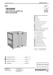
VEX240 - exhausto.de
VEX240 - exhausto.de
VEX240 - exhausto.de

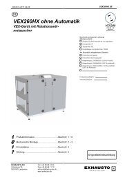
Create successful ePaper yourself
Turn your PDF publications into a flip-book with our unique Google optimized e-Paper software.
Product information - version 3<br />
VEX200 series<br />
Air handling unit<br />
with rotary heat exchanger<br />
<strong>VEX240</strong>: 400-2,350 m3/h 3<br />
VEX250: 700-3,700 700-3 700 m3/h 3<br />
VEX260: 1,100-5,600 m3/h<br />
VEX270-1: 1,300-7,600 m3/h<br />
VEX270-2: 1,800-9,100 m3/h<br />
VEX200<br />
R A N G E<br />
ROTARY<br />
HEAT EXCHANGER
Contents<br />
<strong>VEX240</strong> (400-2,350 m 3 /h) ........................4<br />
- Technical specifications ..............................................................4<br />
- Capacity curves - bag filters .......................................................5<br />
- Capacity curves - compact filters ...............................................6<br />
- Temperature efficiency ..............................................................6<br />
- Sound data ................................................................................7<br />
- Data for the water heating coil ..................................................8<br />
- Data for the motor valve ...........................................................9<br />
- Dimensional sketches .............................................................10<br />
- Variant mo<strong>de</strong>ls ........................................................................11<br />
VEX250 (700-3,700 m 3 /h) ......................12<br />
- Technical specifications ............................................................12<br />
- Capacity curves - bag filters .....................................................13<br />
- Capacity curves - compact filters .............................................14<br />
- Temperature efficiency ............................................................14<br />
- Sound data ..............................................................................15<br />
- Data for the water heating coil ................................................16<br />
- Data for the motor valve .........................................................17<br />
- Dimensional sketches .............................................................18<br />
- Variant mo<strong>de</strong>ls ........................................................................19<br />
VEX260 (1,100-5,600 m 3 /h) ...................20<br />
- Technical specifications ............................................................20<br />
- Capacity curves - bag filters .....................................................21<br />
- Capacity curves - compact filters .............................................22<br />
- Temperature efficiency ............................................................22<br />
- Sound data ..............................................................................23<br />
- Data for the water heating coil ................................................24<br />
- Data for the motor valve .........................................................25<br />
- Dimensional sketches .............................................................26<br />
- Variant mo<strong>de</strong>ls ........................................................................27<br />
VEX270 (700-9,100 m 3 /h) ......................28<br />
- Technical specifications ............................................................28<br />
- Capacity curves - bag filters .....................................................29<br />
- Capacity curves - compact filters .............................................30<br />
- Temperature efficiency ............................................................31<br />
- Sound data ..............................................................................32<br />
- Data for the water heating coil ................................................34<br />
- Data for the motor valve .........................................................35<br />
- Dimensional sketches .............................................................36<br />
- Variant mo<strong>de</strong>ls ........................................................................37<br />
The VEX200 control system..................38<br />
- Function overview ...................................................................39<br />
- Commissioning and operation .................................................40<br />
- Control ...................................................................................41<br />
- Advanced standard functions ..................................................42<br />
- Airflow measurement ..............................................................43<br />
- Technical specifications, modules ............................................44<br />
- Connection to external units ...................................................45<br />
- VEX200 for other control systems ...........................................46<br />
VEX200 General ....................................47<br />
- Conditions for capacity data ....................................................47<br />
- Conditions for sound data and calculation ex............................47<br />
- Water heating coil, principle for connection ............................49<br />
- Motor valve, calculating values ................................................50<br />
- Simplified diagrams .................................................................51<br />
- Cable plans .............................................................................54<br />
- Outdoor solution .....................................................................57<br />
- Service and maintenance .........................................................58<br />
- Disassembling and reassembling the modules / carbon fi lter ....59<br />
www.<strong>exhausto</strong>.com<br />
- Complete electronic documentation<br />
- EXselect product selection program range<br />
for professional calculation.<br />
2<br />
The VEX200 range<br />
– a brief introduction<br />
Cabinet:<br />
The VEX200 cabinet is ma<strong>de</strong> of sheet aluminium-zinc<br />
AZ185 C4, and insulated with 50mm mineral wool.<br />
Single and<br />
modular units:<br />
The <strong>VEX240</strong> and 250 are available as single units where<br />
the <strong>de</strong>pth without the doors is max. 890 mm.<br />
The VEX260 and 270-1/270-2 are supplied as units that<br />
need to be disassembled. The various modules can be moved<br />
separately through openings of at least 825 mm.<br />
Connecting to duct system:<br />
The <strong>VEX240</strong> and 250 are supplied with round spigots,<br />
and the VEX260 and 270 with square connections to the<br />
duct system, with a proprietary fl ange system.<br />
External heating coil:<br />
Heating coils for electricity and water can be purchased as<br />
accessories to the VEX200 range. Heating coils are <strong>de</strong>livered<br />
in an un-insulated housing, the water heating coils are<br />
supplied with a separate control unit and the electrical<br />
heating coils are <strong>de</strong>livered with the control unit mounted.<br />
The heating coils can also be <strong>de</strong>livered in an insulated<br />
housing with control unit mounted and in a version for<br />
outdoor mounting.
Airflow from 400 to 9,100 m 3 /h with<br />
the VEX200 range<br />
Fan housing:<br />
The fans are hung on rails that make it easy to pull out and<br />
service individually. The <strong>de</strong>sign of the suspension system in<br />
which the motor, fan impeller and intake are brought<br />
together, provi<strong>de</strong>s optimum conditions for minimising<br />
vibrations.<br />
EXstream performance:<br />
The entire VEX200 range is supplied with EXHAUSTO’s newly<br />
<strong>de</strong>veloped EXstream impeller, which due to its high effi ciency<br />
and low sound levels, places the units among the best on the<br />
market. Add the use of EFF1 classifi ed motors, and you<br />
get high performance with low SFP fi gures.<br />
3<br />
Outdoor solutions:<br />
The VEX200 range can be supplied with a roof for fi tting<br />
outsi<strong>de</strong>. The roof is split up into sections, giving easy access to<br />
the connection box.<br />
Integrated control:<br />
In the VEX200 range the control system forms an integral part<br />
of the unit, placed just above the motor. All connections are at<br />
the front in the integrated connection box, so that no space is<br />
used above the unit. Cables and measurement sockets are<br />
located on the si<strong>de</strong> of the connection box.<br />
Rotary heat exchanger:<br />
A rotary heat exchanger in aluminium, with low pressure loss<br />
and a temperature effi ciency of 80%. The rotor control<br />
comprises a gear motor with frequency converter.<br />
Bag and compact fi lters:<br />
The VEX200 range is supplied with<br />
a choice of compact or bag fi lters.<br />
Supplied with F5 or F7 fi lters.<br />
Base:<br />
The <strong>VEX240</strong> and 250 are supplied<br />
as standard with feet. It is also<br />
possible to or<strong>de</strong>r a base with<br />
adjustable feet as extra.<br />
The VEX260 and 270 are modular<br />
units and supplied with an integrated<br />
base with adjustable feet.
<strong>VEX240</strong><br />
Technical specifi cations - <strong>VEX240</strong> (400-2,350 m 3 /h)<br />
Unit data<br />
Power consumption 1.6 kW<br />
Max. phase current 11.6 A (Power consumption is not sine shaped)<br />
Electricity supply 1 x 230 V + NE 50 Hz<br />
Principal dimensions excluding spigot, cable connections and base<br />
(if any). Integrated connection box for control system components<br />
4<br />
Height = 1,050 mm, Length = 1,490 mm, Depth = 860 mm<br />
Height = 65 mm (see dimensional sketch)<br />
Cabinet material Aluminium zinc, AZ185, Environmental class C4<br />
Insulation 50 mm mineral wool<br />
Duct connection Ø315 mm<br />
Service doors (can be removed) 2 si<strong>de</strong>-hung doors<br />
Filters<br />
Bag filters<br />
1 F5 (EU5), á 3.9 m<br />
(outdoor air and extraction) Bag filters<br />
Compact filters<br />
Compact filters<br />
2 , 465 x 755 - 10 x 380 mm<br />
1 F7 (EU7), á 4.9 m2 , 465 x 755 - 13 x 380 mm<br />
1 F5 (EU5), á 7.9 m2 , 500 x 755 x 96 mm<br />
1 F7 (EU7), á 12.8 m2 , 500 x 755 x 96 mm<br />
Weight: ready to operate unit<br />
260 kg<br />
Weight: unit prior to fitting<br />
200 kg (excluding doors and fan unit)<br />
Filter control, built into the connection box<br />
(Does not apply to units using other control systems)<br />
2<br />
Con<strong>de</strong>nsation rotor in sea-water proof aluminium<br />
Fan data<br />
Corrugation height 1.6mm<br />
Fan type EXstream, freely revolving B-impeller<br />
Vibration suppression Fan suspen<strong>de</strong>d in vibration dampers<br />
Motor data (per motor) With integrated control For other control systems<br />
Electrical supply (<strong>de</strong>lta/star) 3 x 230 V / 400 V 3 x 230 V / 400 V<br />
Full load current (<strong>de</strong>lta/star) 3 x 2.6 A / 1.5 A 3 x 2.6 A / 1.5 A<br />
Power consumption 0.55 kW 0.55 kW<br />
CEMEP class As EFF1 As EFF1<br />
Frequency converter data With integrated control For other control systems<br />
Electrical input<br />
Electrical output<br />
1 x 230 V<br />
3 x 230 V<br />
No frequency converter<br />
Current overload protection Built-in<br />
Control (Does not apply to units using other control systems) Variable via frequency control<br />
Rotor drive - frequency controlled gear motor<br />
Electrical input 230 V<br />
Phase current 0.3 A<br />
Power consumption 40 W<br />
Current overload protection Built-in<br />
Speed control (with built-in rotation control) Variable from 0.2 to 10 revolutions of the rotor<br />
Accessories<br />
VEX and heating coil for outdoor fitting Special roof and jointing of unit<br />
Water heating coil at toutsi<strong>de</strong> = -20°C , Full heat recovery, volume<br />
flow ratio = 1.0 and supply air temperature 20°C (Control system<br />
valve components are not supplied for other control systems)<br />
Post-heating coil (electricity)<br />
(Control not supplied for other control systems)<br />
None<br />
5.06 kW at 556 l/s (2000 m 3 /h) and<br />
tF / tR = 60 / 37°C<br />
(Weight: 11kg)<br />
6 kW, 1 step, modulating<br />
(Weight: 7 kg)<br />
Mounting base for the <strong>VEX240</strong> Adjustable height 105-135 mm incl. feet<br />
Trim damper and cleaning sector For reduction of leakage air<br />
Carbon filter For odour removal, if any, in the supply air
Capacity curves - with bag filters<br />
<strong>VEX240</strong>-FC - with integrated control<br />
bag fi lters<br />
Capacity curve with F5 filters<br />
SFP curve<br />
Operation curves<br />
A = Pressure loss addition with F7 filter<br />
B = Pressure loss addition via external heating coil<br />
C = Pressure loss addition via cooling units<br />
D = Pressure loss addition via carbon filter<br />
= Area where operation of cooling unit is possible<br />
Conditions for capacity measurements are given on page 47.<br />
To calculate capacity data, we refer you to our product<br />
selection program at www.<strong>exhausto</strong>.com.<br />
5<br />
<strong>VEX240</strong>-X - for other control systems<br />
bag fi lters<br />
Total energy consumption is divi<strong>de</strong>d equally between the<br />
exhaust and supply air fans.<br />
Capacity curves are measured at the following max. frequency:<br />
<strong>VEX240</strong>-FC: 50 Hz - <strong>VEX240</strong>-X: 50 Hz<br />
If a <strong>VEX240</strong> for other control systems is fitted with a<br />
frequency converter, the motor can cope with a load of up to<br />
50 Hz, and the capacity curve above can be used.<br />
<strong>VEX240</strong>
<strong>VEX240</strong><br />
Capacity curves - with compact filters<br />
<strong>VEX240</strong>-FC - with integrated control<br />
compact fi lters<br />
Capacity curve with F5 filters<br />
SFP curve<br />
Operation curves<br />
A = Pressure loss addition with F7 filter<br />
B = Pressure loss addition via external heating coil<br />
C = Pressure loss addition via cooling units<br />
D = Pressure loss addition via carbon filter<br />
= Area where operation of cooling unit is possible<br />
Temperature effi ciency<br />
The temperature efficiency of the VEX unit at<br />
different volume flow ratios is shown here,<br />
calculated as:<br />
Supply air<br />
= 0.8 and 1.0<br />
Extract air<br />
6<br />
<strong>VEX240</strong>-X - for other control systems<br />
compact fi lters<br />
Conditions for capacity measurements are given on page 47.<br />
Total energy consumption is divi<strong>de</strong>d equally between the<br />
exhaust and supply air fans.<br />
Capacity curves are measured at the following max. frequency:<br />
<strong>VEX240</strong>-FC: 50 Hz - <strong>VEX240</strong>-X: 50 Hz<br />
If a <strong>VEX240</strong> for other control systems is fitted with a frequency<br />
converter, the motor can cope with a load of up to 50 Hz,<br />
and the capacity curve above can be used.<br />
�<br />
t = t2.2 - t2.1 = Temperature efficiency<br />
t1.1 - t2.1 t2.1 = Temperature of outdoor air<br />
t2.2 = Temperature of supply air<br />
t1.1 = Temperature of extract air<br />
Extract air = 25°C<br />
Outdoor air = 5°C<br />
Temperature efficiency is given for dry heat<br />
recovery and is increased by con<strong>de</strong>nsation.
Sound data<br />
<strong>VEX240</strong> L WA1 - Suction si<strong>de</strong> <strong>VEX240</strong> L WA2 - Pressure si<strong>de</strong><br />
Suction si<strong>de</strong> (outdoor/extract air):<br />
LW1 = LWA1 + KW LWA1 read<br />
L W1<br />
L W3<br />
Surroundings:<br />
LW3 = LWA1 + KW LWA1 read<br />
LpA3 = LWA1 +KpA KW (dB) KWA KpA Areas 63 125 250 500 1K 2K 4K 8K dB(A) dB(A)<br />
I 10 8 -2 2 -15 -16 -21 -35<br />
II 8 6 6 -5 -18 -20 -25 -35<br />
III 12 11 5 -5 -20 -27 -26 -27<br />
I 8 2 -11 -15 -19 -24 -29 -31 -11 -26<br />
II 9 2 -7 -14 -18 -19 -23 -23 -8 -24<br />
III 19 7 -8 -14 -22 -24 -24 -15 -5 -21<br />
LW2<br />
LW1<br />
1,2,A<br />
2,1,A<br />
1,1,A<br />
2,2,A<br />
Conditions for sound measurements are given on page 47.<br />
LW1<br />
LW2<br />
1 m<br />
2,1,A<br />
7<br />
Pressure si<strong>de</strong> (supply/exhaust air):<br />
LW2 = LWA2 + KW LWA2 read<br />
Areas 63 125 250<br />
KW (dB)<br />
500 1K 2K 4K 8K<br />
I -1 -6 -8 -3 -5 -6 -11 -20<br />
L W2 II 1 -7 3 -9 -6 -8 -12 -16<br />
III 6 3 0 -8 -5 -11 -8 -15<br />
Sound reduction through<br />
water heating coil and carbon filter<br />
LpA3 Insert silencer<br />
(dB)<br />
Component 63 125 250 500 1K 2K 4K 8K<br />
1,2,A<br />
Water heating<br />
coil 1 0 0 1 3 3 2 2<br />
Carbon filter 6 8 4 10 14 16 16 16<br />
<strong>VEX240</strong>
<strong>VEX240</strong><br />
Technical data for water heating coil - optional<br />
Technical specifi cations<br />
Test pressure 3,000 kPa<br />
Max. operating pressure 1,600 kPa<br />
Number of rows of pipes 1<br />
Number of circuits 2<br />
Face area (HxW) 0.350 x 0.350 m<br />
Pipe connection DN15 (1/2’’)<br />
Fin distance 1.6 mm<br />
Weight (without fl uid) 11 kg<br />
Water content 0.7 l<br />
Outsi<strong>de</strong> temperature -12°C<br />
Outsi<strong>de</strong> temperature -20°C<br />
Pressure loss in and across water heating coil<br />
Air si<strong>de</strong><br />
Water si<strong>de</strong><br />
8<br />
Capacity diagrams for water heating coil<br />
Conditions<br />
Water supply temperature t F<br />
Water return temperature t R<br />
Precision of reading and calculated results ± 10%<br />
Extract air temperature 22°C<br />
Volume flow ratio 1,0<br />
Heat recovery 100%<br />
NB<br />
For frost protection using glycol, the output values in<br />
the diagram below must be reduced by 15-20%.<br />
1 l/s = 3,6m 3 /h
Precalculated values for the motor valve<br />
Selection of Kvs value<br />
The kvs values shown in the chart are preselected on the<br />
following basis:<br />
• Two <strong>de</strong>fi ned outsi<strong>de</strong> temperatures<br />
• Defi ned water supply temperature<br />
• Temperature of the extract/supply air 22/20°C<br />
• Airfl ow of 2,000 m3/h If your own data <strong>de</strong>viate from the preselected values in<br />
the chart, the Kvs value has to be calculated manually<br />
using the mo<strong>de</strong>l provi<strong>de</strong>d on page 50.<br />
<strong>VEX240</strong> (2,000 m3/h) Outsi<strong>de</strong><br />
temperature<br />
Water supply Water return Water flow p HCW Kvs p Kvs Pipe connection<br />
[°C] [°C] [°C] [l/h] [kPa] [kPa]<br />
-12 80 31 72 0,3 0,25 8<br />
-12 70 32 80 0,4 0,25 9,5<br />
-12 55 33 150 1,2 0,63 7<br />
-12 55 33 150 1,2 0,40 15<br />
-20 80 35 108 0,5 0,40 9<br />
-20 80 35 108 0,5 0,25 20<br />
-20 70 36 140 0,8 0,63 6<br />
-20 70 36 140 0,8 0,40 14<br />
-20 55 33 252 2,7 1,00 7<br />
-20 55 33 252 2,7 0,63 18<br />
p Kvs: Must be selected in the interval 5-20 kPa<br />
9<br />
DN10 (3/8‘‘)<br />
<strong>VEX240</strong>
<strong>VEX240</strong><br />
Dimensional sketches - <strong>VEX240</strong><br />
<strong>VEX240</strong> - Fan position 1<br />
Unit dimensions in mm<br />
1<br />
1<br />
Water heating coil Electrical heating coil<br />
2<br />
2<br />
10<br />
<strong>VEX240</strong> - Fan position 2<br />
Post heating coil - both electricity and water - measured in mm<br />
Carbon fi lter - measured in mm<br />
1<br />
1<br />
All measurements are exclusive feet (12 mm)<br />
and base (adjustable from 105-135 mm)<br />
2<br />
2<br />
1) Allow a service distance equal to the<br />
<strong>de</strong>pth of the unit in front of the unit<br />
2) Allow min. 200 mm free height for service
Variant mo<strong>de</strong>ls - <strong>VEX240</strong><br />
VEX with compact fi lter<br />
VEX with bag fi lter<br />
NB When using bag fi lters, spigot location B is not an option.<br />
1.1 Extract air 1.2. Exhaust air 2.1 Outdoor air 2.2 Supply air<br />
11<br />
<strong>VEX240</strong>
VEX250<br />
Technical specifi cations - VEX250 (700-3,700 m 3/h)<br />
Unit data<br />
Power consumption 2.7 kW<br />
Max. phase current 8.5 A (Power consumption is assimilated from 2 phases and is not sine shaped)<br />
Electricity supply 3 x 400 V + NE 50 Hz<br />
Principal dimensions excluding spigot, cable connections and base<br />
(if any). Integrated connection box for control system components<br />
12<br />
Height = 1,100 mm, Length = 1,600 mm, Depth = 940 mm<br />
Height = 65 mm (see dimensional sketches)<br />
Cabinet material Aluminium zinc, AZ185, Environmental class C4<br />
Insulation 50 mm mineral wool<br />
Duct connection ø400 mm<br />
Service doors (can be removed) 2 si<strong>de</strong>-hung doors<br />
Filters<br />
(outdoor air and extraction)<br />
Bag filters<br />
Bag filters<br />
Compact filters<br />
Compact filters<br />
1 F5 (EU5), x 4.84 m 2 , 490 x 835 - 13 x 380 mm<br />
1 F7 (EU7), x 5.96 m 2 , 490 x 835 - 16 x 380 mm<br />
1 F5 (EU5), x 9.11 m 2 , 520 x 835 x 96 mm<br />
1 F7 (EU7), x 14.57 m 2 , 520 x 835 x 96 mm<br />
Weight: ready to operate unit<br />
272.5 kg<br />
Weight: unit prior to fitting<br />
194.5 kg (excluding doors and fan unit)<br />
Filter control, built into the connection box<br />
(Does not apply to units using other control systems)<br />
2<br />
Con<strong>de</strong>nsation rotor in sea-water proof aluminium<br />
Fan data<br />
Corrugation height 1.6mm<br />
Fan type EXstream, freely revolving B-impeller<br />
Vibration suppression Fan suspen<strong>de</strong>d in vibration dampers<br />
Motor data (per motor) With integrated control For other control systems<br />
Electrical supply (<strong>de</strong>lta/star) 3 x 230 V / 400 V 3 x 230 V / 400 V<br />
Full load current (<strong>de</strong>lta/star) 3 x 4.0 A / 2.3 A 3 x 4.0 A / 2.3 A<br />
Power consumption 1.1 kW 1.1 kW<br />
CEMEP class EFF1 EFF1<br />
Frequency converter data With integrated control For other control systems<br />
Electrical input<br />
Electrical output<br />
1 x 230 V<br />
3 x 230 V<br />
No frequency converter<br />
Current overload protection<br />
Control (Does not apply to units using other control systems)<br />
Built-in<br />
Variable via frequency control<br />
None<br />
Rotor drive - frequency controlled gear motor<br />
Electrical input 230 V<br />
Phase current 0.3 A<br />
Power consumption 40 W<br />
Current overload protection Built-in<br />
Speed control (with built-in rotation control) Variable from 0.2 to 10 revolutions of the rotor<br />
Accessories<br />
VEX and heating coil for outdoor fitting Special roof and jointing of unit<br />
Water heating coil at toutsi<strong>de</strong> = -20°C , Full heat recovery, volume 10.79 kW at 833 l/s (3000 m<br />
flow ratio = 1.0 and supply air temperature 20°C (Control system<br />
valve components are not supplied for other control systems)<br />
3 /h) and<br />
tF / tR = 60 / 38°C<br />
(Weight: 15.5 kg)<br />
Post-heating coil (electricity)<br />
12 kW, 1 step, modulating<br />
(Control not supplied for other control systems)<br />
(Weight: 24 kg)<br />
Mounting base for the VEX250 Adjustable height 105-135 mm incl. feet<br />
Trim damper and cleaning sector For reduction of leakage air<br />
Carbon filter For odour removal, if any, in the supply air
Capacity curves - with bag filters<br />
VEX250-FC - with integrated control<br />
bag fi lters<br />
Capacity curve with F5 filters<br />
SFP curve<br />
Operation curves<br />
A = Pressure loss addition with F7 filter<br />
B = Pressure loss addition via external heating coil<br />
C = Pressure loss addition via cooling units<br />
D = Pressure loss addition via carbon filter<br />
= Area where operation of cooling unit is possible<br />
Conditions for capacity measurements are given on page 47.<br />
To calculate capacity data, we refer you to our product<br />
selection program at www.<strong>exhausto</strong>.com.<br />
13<br />
VEX250-X - for other control systems<br />
bag fi lters<br />
Total energy consumption is divi<strong>de</strong>d equally between the<br />
exhaust and supply air fans.<br />
Capacity curves are measured at the following max. frequency:<br />
VEX250-FC: 50 Hz - VEX250-X: 50 Hz<br />
If a VEX250 for other control systems is fitted with a frequency<br />
converter, the motor can cope with a load of up to 50 Hz, and<br />
the capacity curve above can be used.<br />
VEX250
VEX250<br />
Capacity curves - with compact filters<br />
VEX250-FC - with integrated control<br />
compact fi lters<br />
Capacity curve with F5 filters<br />
SFP curve<br />
Operation curves<br />
A = Pressure loss addition with F7 filter<br />
B = Pressure loss addition via external heating coil<br />
C = Pressure loss addition via cooling units<br />
D = Pressure loss addition via carbon filter<br />
= Area where operation of cooling unit is possible<br />
Temperature effi ciency<br />
The temperature efficiency of the VEX unit at<br />
different volume flow ratios is shown here,<br />
calculated as:<br />
Supply air<br />
= 0.8 and 1.0<br />
Extract air<br />
14<br />
VEX250-X - for other control systems<br />
compact fi lters<br />
Conditions for capacity measurements are given on page 47.<br />
Total energy consumption is divi<strong>de</strong>d equally between the<br />
exhaust and supply air fans.<br />
Capacity curves are measured at the following max. frequency:<br />
VEX250-FC: 50 Hz - VEX250-X: 50 Hz<br />
If a VEX250 for other control systems is fitted with a frequency<br />
converter, the motor can cope with a load of up to 50 Hz,<br />
and the capacity curve above can be used.<br />
�<br />
t = t2.2 - t2.1 = Temperature efficiency<br />
t1.1 - t2.1 t2.1 = Temperature of outdoor air<br />
t2.2 = Temperature of supply air<br />
t1.1 = Temperature of extract air<br />
Extract air = 25°C<br />
Outdoor air = 5°C<br />
Temperature efficiency is given for dry heat<br />
recovery and is increased by con<strong>de</strong>nsation.
Sound data<br />
VEX250 L WA1 - Suction si<strong>de</strong> VEX250 L WA2 - Pressure si<strong>de</strong><br />
Suction si<strong>de</strong> (outdoor/extract air):<br />
LW1 = LWA1 + KW LWA1 read<br />
Surroundings:<br />
LW3 = LWA1 + KW LWA1 read<br />
LpA3 = LWA1 +KpA KW (dB) KWA KpA Areas 63 125 250 500 1K 2K 4K 8K dB(A) dB(A)<br />
I 9 0 -4 3 -13 -17 -24 -39<br />
LW1 II 5 2 4 -1 -12 -18 -25 -37<br />
III 8 7 7 -1 -13 -21 -28 -27<br />
I 2 -6 -15 -19 -23 -28 -33 -37 -16 -32<br />
L W3 II 1 -4 -11 -17 -20 -25 -27 -26 -13 -29<br />
LW2<br />
LW1<br />
III 5 2 0 -9 -15 -15 -16 -14 -4 -20<br />
1,2,A<br />
2,1,A<br />
1,1,A<br />
2,2,A<br />
Conditions for sound measurements are given on page 47.<br />
LW1<br />
LW2<br />
1 m<br />
2,1,A<br />
15<br />
Pressure si<strong>de</strong> (supply/exhaust air):<br />
LW2 = LWA2 + KW LWA2 read<br />
K W<br />
(dB)<br />
Areas 63 125 250 500 1K 2K 4K 8K<br />
I -2 -10 -12 0 -6 -9 -16 -26<br />
LW2 II -4 -9 0 -5 -4 -9 -15 -26<br />
III 1 -3 2 -4 -4 -9 -19 -11<br />
Sound reduction through<br />
water heating coil and carbon filter<br />
LpA3 Insert silencer<br />
(dB)<br />
Component 63 125 250 500 1K 2K 4K 8K<br />
1,2,A<br />
Water heating<br />
coil 1 1 1 1 3 2 2 1<br />
Carbon filter 6 8 4 10 14 16 16 16<br />
VEX250
VEX250<br />
Technical data for water heating coil - optional<br />
Technical specifi cations<br />
Test pressure 3,000 kPa<br />
Max. operating pressure 1,600 kPa<br />
Number of rows of pipes 1<br />
Number of circuits 2<br />
Face area (HxW) 0.420 x 0.520 m<br />
Pipe connection DN15 (1/2’’)<br />
Fin distance 1.6 mm<br />
Weight (without fl uid) 15.5 kg<br />
Water content 1.3 l<br />
Outsi<strong>de</strong> temperature -12°C<br />
Pressure loss in and across water heating coil<br />
Air si<strong>de</strong><br />
Outsi<strong>de</strong> temperature -20°C<br />
Water si<strong>de</strong><br />
16<br />
Capacity diagrams for water heating coil<br />
Conditions<br />
Water supply temperature t F<br />
Water return temperature t R<br />
Precision of reading and calculated results ± 10%<br />
Extract air temperature 22°C<br />
Volume flow ratio 1,0<br />
Heat recovery 100%<br />
NB<br />
For frost protection using glycol, the output values in<br />
the diagram below must be reduced by 15-20%.<br />
1 l/s = 3,6 m 3 /h
Precalculated values for the motor valve<br />
Selection of Kvs value<br />
The kvs values shown in the chart are preselected on the<br />
following basis:<br />
• Two <strong>de</strong>fi ned outsi<strong>de</strong> temperatures<br />
• Defi ned water supply temperature<br />
• Temperature of the extract/supply air 22/20°C<br />
• Airfl ow of 3,000 m3/h If your own data <strong>de</strong>viate from the preselected values in<br />
the chart, the Kvs value has to be calculated manually<br />
using the mo<strong>de</strong>l provi<strong>de</strong>d on page 50.<br />
VEX250 (3,000 m3/h) Outsi<strong>de</strong><br />
temperature<br />
Water supply Water return Water flow p HCW Kvs p Kvs Pipe connection<br />
[°C] [°C] [°C] [l/h] [kPa] [kPa]<br />
-12 80 31 108 0,3 0,40 9<br />
-12 80 31 108 0,3 0,25 20<br />
-12 70 31 144 0,4 0,63 6,5<br />
-12 70 31 144 0,4 0,40 14<br />
-12 55 32 252 1,0 1,00 7<br />
-12 55 32 252 1,0 0,63 18<br />
-20 80 34 180 0,5 0,63 8,5<br />
-20 70 34 216 0,7 0,63 10,5<br />
-20 55 35 360 2,0 1,60 5<br />
-20 55 35 360 2,0 1,60 14<br />
p Kvs: Must be selected in the interval 5-20 kPa<br />
17<br />
DN10 (3/8‘‘)<br />
VEX250
VEX250<br />
Dimensional sketches - VEX250<br />
VEX250 - Fan position 1<br />
Unit dimensions in mm<br />
1<br />
1<br />
2<br />
18<br />
VEX250 - Fan position 2<br />
Post heating coil - both electricity and water - measured in mm<br />
Water heating coil Electrical heating coil<br />
Carbon fi lter - measured in mm<br />
2<br />
1<br />
1<br />
All measurements are exclusive feet (12 mm)<br />
and base (adjustable from 105-135 mm)<br />
2<br />
2<br />
1) Allow a service distance equal to the<br />
<strong>de</strong>pth of the unit in front of the unit<br />
2) Allow min. 200 mm free height for service
Variant mo<strong>de</strong>ls - VEX250<br />
VEX with compact fi lter<br />
VEX with bag fi lter<br />
NB When using bag fi lters, spigot location B is not an option.<br />
1.1 Extract air 1.2. Exhaust air 2.1 Outdoor air 2.2 Supply air<br />
19<br />
VEX250
VEX260<br />
Technical specifi cations - VEX260 (1,100-5,600 m 3/h)<br />
Unit data<br />
Power consumption 4.8 kW<br />
Max. phase current 16.0A (Power consumption is assimilated from 2 phases and is not sine shaped)<br />
Electricity supply 3 x 400 V + NE 50 Hz<br />
Principal dimensions excluding spigot, cable connections and base<br />
(if any). Integrated connection box for control system components<br />
20<br />
Height = 1,570 mm, Length = 1,820 mm, Depth = 1,265 mm<br />
Height = 65 mm (see dimensional sketches)<br />
Cabinet material Aluminium zinc, AZ185, Environmental class C4<br />
Insulation 50 mm mineral wool<br />
Duct connection 400 x 800 mm<br />
Service doors (can be removed) 2 si<strong>de</strong>-hung doors, 1 removable door<br />
Filters<br />
(outdoor air and extraction)<br />
Bag filters (F5)<br />
Bag filters (F5)<br />
Bag filters (F7)<br />
Bag filters (F7)<br />
Compact filters (F5)<br />
Compact filters (F7)<br />
1 F5 (EU5), x 2.5 m 2 , 490 x 592 - 5 x 380 mm<br />
1 F5 (EU5), x 3.0 m 2 , 592 x 592 - 6 x 380 mm<br />
1 F7 (EU7), x 4.0 m 2 , 490 x 592 - 8 x 380 mm<br />
1 F7 (EU7), x 5.0 m 2 , 592 x 592 - 10 x 380 mm<br />
3 F5 (EU5), x 5.2 m 2 , 650 x 380 x 96 mm<br />
3 F7 (EU7), x 8.4 m 2 , 650 x 380 x 96 mm<br />
Weight: ready to operate unit (3 sections)<br />
525 kg (2 x 166,5 kg, 1 x 137 kg)<br />
Weight: unit prior to fitting (excluding doors, fan units and base) Fan units: 117 kg each, Rotor section: 127,5 kg<br />
Filter control, built into the connection box<br />
(Does not apply to units using other control systems)<br />
2<br />
Con<strong>de</strong>nsation rotor in sea-water proof aluminium<br />
Fan data<br />
Corrugation height 1.6 mm<br />
Fan type EXstream, freely revolving B-impeller<br />
Vibration suppression Fan suspen<strong>de</strong>d in vibration dampers<br />
Motor data (per motor) With integrated control For other control systems<br />
Electrical supply (<strong>de</strong>lta/star) 3 x 230 V / 400 V 3 x 230 V / 400 V<br />
Full load current (<strong>de</strong>lta/star) 3 x 7.8 A / 4.5 A 3 x 7.8 A / 4.5 A<br />
Power consumption 2.2 kW 2.2 kW<br />
CEMEP class EFF1 EFF1<br />
Frequency converter data With integrated control For other control systems<br />
Electrical input<br />
Electrical output<br />
1 x 230 V<br />
3 x 230 V<br />
No frequency converter<br />
Current overload protection<br />
Control (Does not apply to units using other control systems)<br />
Rotor drive - frequency controlled gear motor<br />
Built-in<br />
Variable via frequency control<br />
None<br />
Electrical input 230 V<br />
Phase current 0.3 A<br />
Power consumption 40 W<br />
Current overload protection Built-in<br />
Speed control (with built-in rotation control)<br />
Accessories<br />
Variable from 0.2 to 10 revolutions of the rotor<br />
VEX and heating coil for outdoor fitting Special roof and jointing of unit<br />
Water heating coil at toutsi<strong>de</strong> = -20°C , Full heat recovery, volume 13.08 kW at 1389 l/s (5000 m<br />
flow ratio = 1.0 and supply air temperature 20°C (Control system<br />
valve components are not supplied for other control systems)<br />
3 /h) and<br />
tF / tR = 60 / 37°C<br />
(Weight: 9.2 kg)<br />
Post-heating coil (electricity)<br />
14kW, 1 step, modulating<br />
(Control not supplied for other control systems)<br />
(Weight: 23 kg)<br />
Trim damper and cleaning sector For reduction of leakage air<br />
Carbon filter For odour removal, if any, in the supply air
Capacity curves - with bag filters<br />
VEX260-FC - with integrated control<br />
bag fi lters<br />
Capacity curve with F5 filters<br />
SFP curve<br />
Operation curves<br />
A = Pressure loss addition with F7 filter<br />
B = Pressure loss addition via external heating coil<br />
C = Pressure loss addition via cooling units<br />
D = Pressure loss addition via carbon filter<br />
= Area where operation of cooling unit is possible<br />
Conditions for capacity measurements are given on page 47.<br />
To calculate capacity data, we refer you to our product<br />
selection program at www.<strong>exhausto</strong>.com.<br />
21<br />
VEX260-X - for other control systems<br />
bag fi lters<br />
Total energy consumption is divi<strong>de</strong>d equally between the<br />
exhast and supply air fans.<br />
Capacity curves are measured at the following max. frequency:<br />
VEX260-FC: 52.5 Hz - VEX260-X: 50 Hz<br />
If a VEX260 for other control systems is fitted with a frequency<br />
converter, the motor can cope with a load of up to 52.5 Hz, and<br />
the capacity curve above can be used.<br />
VEX260
VEX260<br />
Capacity curves - with compact filters<br />
VEX260-FC - with integrated control<br />
compact fi lters<br />
Capacity curve with F5 filters<br />
SFP curve<br />
Operation curves<br />
A = Pressure loss addition with F7 filter<br />
B = Pressure loss addition via external heating coil<br />
C = Pressure loss addition via cooling units<br />
D = Pressure loss addition via carbon filter<br />
= Area where operation of cooling unit is possible<br />
Temperature effi ciency<br />
The temperature efficiency of the VEX unit at<br />
different volume flow ratios is shown here,<br />
calculated as:<br />
Supply air<br />
= 0.8 and 1.0<br />
Extract air<br />
22<br />
VEX260-X - for other control systems<br />
compact fi lters<br />
Conditions for capacity measurements are given on page 47.<br />
Total energy consumption is divi<strong>de</strong>d equally between the<br />
exhaust and supply air fans.<br />
Capacity curves are measured at the following max. frequency:<br />
VEX260-FC: 52.5 Hz - VEX260-X: 50 Hz<br />
If a VEX260 for other control systems is fitted with a frequency<br />
converter, the motor can cope with a load of up to 52.5 Hz, and<br />
the capacity curve above can be used.<br />
�<br />
t = t2.2 - t2.1 = Temperature efficiency<br />
t1.1 - t2.1 t2.1 = Temperature of outdoor air<br />
t2.2 = Temperature of supply air<br />
t1.1 = Temperature of extract air<br />
Extract air = 25°C<br />
Outdoor air = 5°C<br />
Temperature efficiency is given for dry heat<br />
recovery and is increased by con<strong>de</strong>nsation.
Sound data - VEX260<br />
VEX260 L WA1 - Suction si<strong>de</strong> VEX260 L WA2 - Pressure si<strong>de</strong><br />
Suction si<strong>de</strong> (outdoor/extract air):<br />
LW1 = LWA1 + KW LWA1 read<br />
Surroundings:<br />
LW3 = LWA1 + KW LWA1 read<br />
LpA3 = LWA1 +KpA KW (dB) KWA KpA Areas 63 125 250 500 1K 2K 4K 8K dB(A) dB(A)<br />
I 5 6 -3 0 -7 -9 -14 -24<br />
LW1 II 3 2 4 -2 -7 -11 -18 -28<br />
III 6 10 2 -2 -10 -16 -22 -23<br />
I 18 10 -7 -12 -11 -16 -24 -28 -3 -20<br />
L W3 II 15 7 -2 -9 -10 -14 -21 -20 -3 -20<br />
LW2<br />
LW1<br />
III 20 18 7 1 -1 -4 -8 -6 8 -9<br />
1,2,A<br />
2,1,A<br />
1,1,A<br />
2,2,A<br />
Conditions for sound measurements are given on page 47.<br />
LW1<br />
LW2<br />
1 m<br />
2,1,A<br />
23<br />
Pressure si<strong>de</strong> (supply/exhaust air):<br />
LW2 = LWA2 + KW LWA2 read<br />
K W<br />
(dB)<br />
Areas 63 125 250 500 1K 2K 4K 8K<br />
I -8 -13 -12 -6 -3 -8 -12 -18<br />
LW2 II -9 -15 -3 -5 -3 -9 -12 -19<br />
III -4 -1 -5 -3 -3 -10 -19 -17<br />
Sound reduction through<br />
water heating coil and carbon filter<br />
LpA3 Insert silencer<br />
(dB)<br />
Component 63 125 250 500 1K 2K 4K 8K<br />
1,2,A<br />
Water heating<br />
coil 1 1 1 1 0 1 1 1<br />
Carbon filter 6 8 4 10 14 16 16 16<br />
VEX260
VEX260<br />
Technical data for water heating coil - optional<br />
Technical specifi cations<br />
Test pressure 3,000 kPa<br />
Max. operating pressure 1,600 kPa<br />
Number of rows of pipes 1<br />
Number of circuits 4<br />
Face area (HxW) 0.400 x 0.800 m<br />
Pipe connection DN15 (1/2’’)<br />
Fin distance 1.8 mm<br />
Weight (without fl uid) 9.2 kg<br />
Water content 1.3 l<br />
Outsi<strong>de</strong> temperature -12°C<br />
Pressure loss in and across water heating coil<br />
Air si<strong>de</strong><br />
Outsi<strong>de</strong> temperature -20°C<br />
Water si<strong>de</strong><br />
24<br />
Capacity diagrams for water heating coil<br />
Conditions<br />
Water supply temperature t F<br />
Water return temperature t R<br />
Precision of reading and calculated results ± 10%<br />
Extract air temperature 22°C<br />
Volume flow ratio 1,0<br />
Heat recovery 100%<br />
NB<br />
For frost protection using glycol, the output values in<br />
the diagram below must be reduced by 15-20%.<br />
1 l/s = 3,6 m 3 /h
Precalculated values for the motor valve<br />
Selection of Kvs value<br />
The kvs values shown in the chart are preselected on the<br />
following basis:<br />
• Two <strong>de</strong>fi ned outsi<strong>de</strong> temperatures<br />
• Defi ned water supply temperature<br />
• Temperature of the extract/supply air 22/20°C<br />
• Airfl ow of 5,000 m3/h If your own data <strong>de</strong>viate from the preselected values in<br />
the chart, the Kvs value has to be calculated manually<br />
using the mo<strong>de</strong>l provi<strong>de</strong>d on page 50.<br />
VEX260 (5,000 m3/h) Outsi<strong>de</strong><br />
temperature<br />
Water supply Water return Water flow p HCW Kvs p Kvs Pipe connection<br />
[°C] [°C] [°C] [l/h] [kPa] [kPa]<br />
-12 80 30 180 0,3 0,63 8,5<br />
-12 70 31 225 0,5 0,63 11<br />
-12 55 33 396 1,3 1,60 6<br />
-12 55 33 396 1,3 1,00 14<br />
-20 80 34 245 0,5 1,00 7<br />
-20 80 34 245 0,5 0,63 18<br />
25<br />
DN10 (3/8‘‘)<br />
-20 70 36 324 1,0 1,00 11<br />
-20 55 38 684 3,4 2,50 7 DN15 (1/2‘‘)<br />
-20 55 38 684 3,4 1,60 15 DN10 (3/8‘‘)<br />
p Kvs: Must be selected in the interval 5-20 kPa<br />
VEX260
VEX260<br />
Dimensional sketches - VEX260<br />
VEX260 - Fan position 1<br />
Unit dimensions in mm<br />
1<br />
1<br />
2<br />
26<br />
VEX260 - Fan position 2<br />
Post-heating coil - both electricity and water - measured in mm<br />
Water heating coil Electrical heating coil<br />
Carbon fi lter - measured in mm<br />
2<br />
1<br />
1<br />
2<br />
2<br />
1) Allow a service distance equal to the<br />
<strong>de</strong>pth of the unit in front of the unit<br />
2) Allow min. 200 mm free height for service<br />
* From the factory, the height of the base is set to<br />
200 mm. It can, however, be adjusted in the<br />
range 150–240 mm.
Variant mo<strong>de</strong>ls - VEX260<br />
VEX with compact fi lter<br />
VEX with bag fi lter<br />
NB When using bag fi lters, spigot location B is not an option.<br />
1.1 Extract air 1.2 Exhaust air 2.1 Outdoor air 2.2 Supply air<br />
27<br />
VEX260
VEX270<br />
Technical specifi cations - VEX270 (1,300-9,100 m 3/h)<br />
Unit data VEX270-1 VEX270-2<br />
Power consumption 5.9 kW 9.1 kW<br />
Max. phase current 19.0 A (Power consumption is assimilated from 2<br />
phases and is not sine shaped)<br />
19.3 A<br />
Electricity supply 3 x 400 V + NE 50 Hz 3 x 400 V + NE 50 Hz<br />
Principal dimensions excluding spigot, cable connections and base (if any).<br />
Integrated connection box for control system components<br />
28<br />
Height = 1,800 mm, Length = 2,050 mm, Depth = 1,525 mm<br />
Height = 65 mm (see dimensional sketches)<br />
Cabinet material Aluminium zinc, AZ185, Environmental class C4<br />
Insulation 50 mm mineral wool<br />
Duct connection 500 x 1000 mm<br />
Service doors (can be removed) 2 si<strong>de</strong>-hung doors, 1 removable door<br />
Filters<br />
(outdoor air and extraction)<br />
Bag filters<br />
Bag filters<br />
Compact filters<br />
Compact filters<br />
3 F5 (EU5), x 4.3 m 2 , 743 x 470 - 5 x 535 mm<br />
3 F7 (EU7), x 6.6 m 2 , 743 x 470 - 8 x 535 mm<br />
3 F5 (EU5), x 7.9 m 2 , 800 x 469 x 96 mm<br />
3 F7 (EU7), x 12.8 m 2 , 800 x 469 x 96 mm<br />
Weight: ready to operate unit (3 sections)<br />
VEX270-1: 734 kg (2 x 240 kg, 1 x 187 kg)<br />
Weight: unit prior to fitting (excluding doors, fan units and base) VEX270-2: 750 kg (2 x 248 kg, 1 x 187 kg)<br />
Fan units: 170.5 kg each, Rotor section: 187 kg<br />
Filter control, built into the connection box<br />
(Does not apply to units using other control systems)<br />
2<br />
Con<strong>de</strong>nsation rotor in sea-water proof aluminium Corrugation height 1.6mm<br />
Fan data<br />
Fan type EXstream, freely revolving B-impeller<br />
Vibration suppression Fan suspen<strong>de</strong>d in vibration dampers<br />
Motor data (per motor) VEX270-1<br />
With integrated control<br />
VEX270-2<br />
With integrated control<br />
VEX270-2<br />
For other control systems<br />
Electrical supply (<strong>de</strong>lta/star) 3 x 230 V / 400 V 3 x 230 V / 400 V 3 x 230 V / 400 V<br />
Full load current (<strong>de</strong>lta/star) 3 x 10.2 A / 5.8 A 3 x 13.1 A / 7.6 A 3 x 13.1 A / 7.6 A<br />
Power consumption 3.0 kW 4.0 kW 4.0 kW<br />
CEMEP class EFF1 EFF1 EFF1<br />
Frequency converter data<br />
Electrical input 1 x 230 V 3 x 400 V No frequency converter<br />
Electrical output 3 x 230 V 3 x 400 V<br />
Current overload protection Built-in Built-in None<br />
Control (Does not apply to units<br />
using other control systems)<br />
Variable via frequency control Variable via frequency control<br />
Rotor drive - frequency controlled gear motor<br />
Electrical input 230 V<br />
Phase current 0.3 A<br />
Power consumption 40 W<br />
Current overload protection Built-in<br />
Speed control (with built-in rotation control) Variable from 0.2 to 10 revolutions of the rotor<br />
Accessories<br />
VEX and heating coil for outdoor fitting Special roof and jointing of unit<br />
Water heating coil at toutsi<strong>de</strong> = -20°C , Full heat recovery, volume flow<br />
ratio = 1.0 and supply air temperature 20°C (Control system valve components<br />
are not supplied for other control systems)<br />
Post heating coil (electricity)<br />
(Control not supplied for other control systems)<br />
16.34 kW at 1667 l/s (6000 m 3 /h) and tF / tR = 60 / 32°C<br />
19.86 kW at 2028 l/s (7300 m 3 /h) and tF / tR = 60 / 35°C<br />
(Weight: 15 kg)<br />
21 kW, 1 step, modulating<br />
(Weight: 31 kg)<br />
Trim damper and cleaning sector For reduction of leakage air<br />
Carbon filter For odour removal, if any, in the supply air
Capacity curves - with bag filters<br />
VEX270-1-FC with integrated control<br />
Bag fi lters<br />
VEX270-2-FC with integrated control<br />
Bag fi lters<br />
29<br />
Capacity curve with F5 filters<br />
SFP curve<br />
Operation curves<br />
A = Pressure loss addition with F7 filter<br />
B = Pressure loss addition via external heating coil<br />
C = Pressure loss addition via cooling units<br />
D = Pressure loss addition via carbon filter<br />
= Area where operation of cooling unit is possible<br />
Conditions for capacity measurements are given on page 47.<br />
To calculate capacity data, we refer you to our product<br />
selection program at www.<strong>exhausto</strong>.com.<br />
Total energy consumption is divi<strong>de</strong>d equally<br />
between the exhaust and supply air fans.<br />
Capacity curves are measured at the following max. frequency:<br />
VEX270-1-FC: 41,5 Hz<br />
VEX270-2-FC: 49 Hz<br />
VEX270-2-X: 50 Hz<br />
If a VEX270-2 for other control systems is fitted with a frequency<br />
converter, the motor can cope with a load of up to 49 Hz, and<br />
the capacity curve for VEX270-2-FC can be used.<br />
VEX270-2-X for other control systems<br />
Bag fi lters<br />
VEX270
VEX270<br />
Capacity curves - with compact filters<br />
VEX270-1-FC with integrated control<br />
Compact fi lters<br />
VEX270-2-FC with integrated control<br />
Compact fi lters<br />
30<br />
Capacity curve with F5 filters<br />
SFP curve<br />
Operation curves<br />
A = Pressure loss addition with F7 filter<br />
B = Pressure loss addition via external heating coil<br />
C = Pressure loss addition via cooling units<br />
D = Pressure loss addition via carbon filter<br />
= Area where operation of cooling unit is possible<br />
Conditions for capacity measurements are given on page 47.<br />
To calculate capacity data, we refer you to our product<br />
selection program at www.<strong>exhausto</strong>.com.<br />
Total energy consumption is divi<strong>de</strong>d equally<br />
between the exhaust and supply air fans.<br />
Capacity curves are measured at the following max. frequency:<br />
VEX270-1-FC: 41,5 Hz<br />
VEX270-2-FC: 49 Hz<br />
VEX270-2-X: 50 Hz<br />
If a VEX270-2 for other control systems is fitted with a frequency<br />
converter, the motor can cope with a load of up to 49 Hz, and<br />
the capacity curve for VEX270-2-FC can be used.<br />
VEX270-2-X for other control systems<br />
Compact fi lters
Temperature effi ciency<br />
The temperature efficiency of the VEX unit at<br />
different volume flow ratios is shown here,<br />
calculated as:<br />
Supply air<br />
= 0.8 and 1.0<br />
Extract air<br />
31<br />
�<br />
t = t2.2 - t2.1 = Temperature efficiency<br />
t1.1 - t2.1 t2.1 = Temperature of outdoor air<br />
t2.2 = Temperature of supply air<br />
t1.1 = Temperature of extract air<br />
Extract air = 25°C<br />
Outdoor air = 5°C<br />
Temperature efficiency is given for dry heat<br />
recovery and is increased by con<strong>de</strong>nsation.<br />
VEX270
VEX270<br />
Sound data - VEX270-1<br />
VEX270-1 L WA1 - Suction si<strong>de</strong> VEX270-1 L WA2 - Pressure si<strong>de</strong><br />
Suction si<strong>de</strong> (outdoor/extract air):<br />
LW1 = LWA1 + KW LWA1 read<br />
Surroundings:<br />
LW3 = LWA1 + KW LWA1 read<br />
LpA3 = LWA1 +KpA KW (dB) KWA KpA Areas 63 125 250 500 1K 2K 4K 8K dB(A) dB(A)<br />
I 6 2 0 1 -8 -14 -20 -27<br />
L W1 II 4 1 6 -4 -8 -15 -22 -32<br />
III 6 8 2 -1 -10 -19 -27 -25<br />
I 14 16 -7 -9 -11 -17 -23 -27 -1 -18<br />
L W3 II 17 9 0 -8 -9 -14 -19 -21 -2 -19<br />
LW2<br />
LW1<br />
III 23 19 3 1 0 -5 -10 -11 8 -9<br />
1,2,A<br />
2,1,A<br />
1,1,A<br />
2,2,A<br />
Conditions for sound measurements are given on page 47.<br />
LW1<br />
LW2<br />
1 m<br />
2,1,A<br />
32<br />
Pressure si<strong>de</strong> (supply/exhaust air):<br />
LW2 = LWA2 + KW LWA2 read<br />
K W<br />
(dB)<br />
Areas 63 125 250 500 1K 2K 4K 8K<br />
I -9 -10 -9 -3 -3 -10 -14 -20<br />
L W2 II -9 -13 -2 -3 -3 -10 -11 -20<br />
III -8 1 -7 -1 -6 -15 -21 -9<br />
Sound reduction through<br />
water heating coil and carbon filter<br />
LpA3 Insert silencer<br />
(dB)<br />
Component 63 125 250 500 1K 2K 4K 8K<br />
1,2,A<br />
Water heating<br />
coil 1 1 1 1 0 1 1 1<br />
Carbon filter 6 8 4 10 14 16 16 16
Sound data - VEX270-2<br />
VEX270-2 L WA1 - Suction si<strong>de</strong> VEX270-2 L WA2 - Pressure si<strong>de</strong><br />
Suction si<strong>de</strong> (outdoor/extract air):<br />
LW1 = LWA1 + KW LWA1 read<br />
L W1<br />
Surroundings:<br />
LW3 = LWA1 + KW LWA1 read<br />
LpA3 = LWA1 +KpA KW (dB) KWA KpA Areas 63 125 250 500 1K 2K 4K 8K dB(A) dB(A)<br />
I<br />
5 1 -1 1 -7 -11 -18 -27<br />
II<br />
3 0 5 -3 -8 -15 -23 -33<br />
III 4 11 2 -1 -9 -20 -28 -25<br />
I 15 8 -7 -10 -11 -16 -23 -28 -4 -21<br />
L W3 II 16 7 -4 -9 -10 -17 -23 -25 -4 -21<br />
LW2<br />
LW1<br />
III 21 18 0 -1 -2 -7 -13 -13 6 -11<br />
1,2,A<br />
2,1,A<br />
1,1,A<br />
2,2,A<br />
Conditions for sound measurements are given on page 47.<br />
LW1<br />
LW2<br />
1 m<br />
2,1,A<br />
33<br />
Pressure si<strong>de</strong> (supply/exhaust air):<br />
LW2 = LWA2 + KW LWA2 read<br />
L W2<br />
K W<br />
(dB)<br />
Areas 63 125 250 500 1K 2K 4K 8K<br />
I<br />
-9 -13 -11 -4 -3 -8 -13 -19<br />
II<br />
-8 -13 -5 -2 -3 -10 -14 -20<br />
III -7 1 -6 -1 -3 -13 -22 -13<br />
Sound reduction through<br />
water heating coil and carbon filter<br />
LpA3 Insert silencer<br />
(dB)<br />
Component 63 125 250 500 1K 2K 4K 8K<br />
1,2,A<br />
Water heating<br />
coil 1 1 1 1 0 1 1 1<br />
Carbon filter 6 8 4 10 14 16 16 16<br />
VEX270
VEX270<br />
Technical data for water heating coil - optional<br />
Technical specifi cations<br />
Test pressure 3,000 kPa<br />
Max. operating pressure 1,600 kPa<br />
Number of rows of pipes 2<br />
Number of circuits 10<br />
Face area (HxW) 0.500 x 1.000 m<br />
Pipe connection DN25 (1’’)<br />
Fin distance 3.6 mm<br />
Weight (without fl uid) 15 kg<br />
Water content 4.1 l<br />
Outsi<strong>de</strong> temperature -12°C<br />
Pressure loss in and across water heating coil<br />
Air si<strong>de</strong><br />
Outsi<strong>de</strong> temperature -20°C<br />
Water si<strong>de</strong><br />
34<br />
Capacity diagrams for water heating coil<br />
Conditions<br />
Water supply temperature t F<br />
Water return temperature t R<br />
Precision of reading and calculated results ± 10%<br />
Extract air temperature 22°C<br />
Volume flow ratio 1,0<br />
Heat recovery 100%<br />
NB<br />
For frost protection using glycol, the output values in<br />
the diagram below must be reduced by 15-20%.<br />
1 l/s = 3,6 m 3 /h
Precalculated values for the motor valve<br />
Selection of Kvs value<br />
The kvs values shown in the chart are preselected on the<br />
following basis:<br />
• Two <strong>de</strong>fi ned outsi<strong>de</strong> temperatures<br />
• Defi ned water supply temperature<br />
• Temperature of the exract/supply air 22/20°C<br />
• Airfl ow of 6,000 m3/h and 7,300 m3/h If your own data <strong>de</strong>viate from the preselected values in<br />
the chart, the Kvs value has to be calculated manually<br />
using the mo<strong>de</strong>l provi<strong>de</strong>d on page 50.<br />
VEX270 (6,000 m3/h) Outsi<strong>de</strong><br />
temperature<br />
Water supply Water return Water flow p HCW Kvs p Kvs Pipe connection<br />
[°C] [°C] [°C] [l/h] [kPa] [kPa]<br />
-12 80 25 216 0,1 0,63 10,5<br />
-12 70 27 252 0,2 1,00 7<br />
-12 70 27 252 0,2 0,63 18<br />
-12 55 30 468 0,4 1,60 8<br />
-20 80 28 288 0,2 1,00 9<br />
-20 70 30 360 0,3 1,60 5<br />
35<br />
DN10 (3/8‘‘)<br />
-20 70 30 360 0,3 1,00 14<br />
-20 55 34 684 1,3 2,50 7 DN15(1/2‘‘)<br />
-20 55 34 684 1,3 1,60 15 DN10 (3/8‘‘)<br />
p Kvs: Must be selected in the interval 5-20 kPa<br />
VEX270 (7,300 m3/h) Outsi<strong>de</strong><br />
temperature<br />
Water supply Water return Water flow p HCW Kvs p Kvs Pipe connection<br />
[°C] [°C] [°C] [l/h] [kPa] [kPa]<br />
-12 80 27 252 0,1 1,00 7<br />
-12 80 27 252 0,1 0,63 18<br />
DN10 (3/8‘‘)<br />
-12 70 29 324 0,2 1,00 11<br />
-12 55 32 612 0,7 2,50 6 DN15 (1/2‘‘)<br />
-12 55 32 612 0,7 1,60 13<br />
-20 80 31 360 0,3 1,60 5<br />
-20 80 31 360 0,3 1,00 14<br />
DN10 (3/8‘‘)<br />
-20 70 33 468 0,4 1,60 8<br />
-20 55 37 972 1,6 4,00 6 DN20 (3/4‘‘)<br />
-20 55 37 972 1,6 2,50 13 DN15 (1/2‘‘)<br />
p Kvs: Must be selected in the interval 5-20 kPa<br />
VEX270
VEX270<br />
Dimensional sketches - VEX270<br />
VEX270 - Fan position 1<br />
Unit dimensions in mm<br />
1<br />
1<br />
2<br />
36<br />
VEX270 - Fan position 2<br />
Post-heating coil - both electricity and water - measured in mm<br />
Water heating coil Electrical heating coil<br />
Carbon fi lter - measured in mm<br />
2<br />
1<br />
1<br />
2<br />
2<br />
1) Allow a service distance equal to the<br />
<strong>de</strong>pth of the unit in front of the unit<br />
2) Allow min. 200 mm free height for service<br />
* From the factory, the height of the base is set to<br />
200 mm. It can, however, be adjusted in the<br />
range 150–240 mm.
Variant mo<strong>de</strong>ls - VEX270<br />
VEX with compact fi lter<br />
VEX with bag fi lter<br />
NB When using bag fi lters, spigot location B is not an option.<br />
1.1 Extract air 1.2. Exhaust air 2.1 Outdoor air 2.2 Supply air<br />
37<br />
VEX270
The VEX200 series: Control system<br />
VEX200 Control system<br />
Simple p to operate p<br />
and with an option for advanced control<br />
Behind the simple user interface, the<br />
advanced VEX200 control ensures the<br />
efficient and economic operation of the<br />
air handling unit. The control can also<br />
be adjusted to the daily rhythms of the<br />
location, whether it is a school, office or<br />
meeting room.<br />
The key functions are:<br />
• Simple operation using the DISPLAY and/or TOUCH panel<br />
• 3 levels of operation of the control ensure that all users can<br />
operate the unit in the best way<br />
• 3 operating levels adapt the ventilation to the actual<br />
requirement: Economy / Stand-by / Comfort<br />
• Built-in weekly timer with graphic display<br />
Integrated control<br />
The connection box is integrally mounted and located<br />
on the top of the VEX so that it is easy to access and operate.<br />
The filter controls are placed in the box, and the DISPLAY<br />
panel is factory-fitted and insi<strong>de</strong> the box on <strong>de</strong>livery.<br />
The DISPLAY panel can be positioned as required.<br />
The motor controls are<br />
placed in a separate<br />
compartment, close to<br />
the fan motors.<br />
The motor control is<br />
positioned for ease of<br />
access for operation<br />
and service purposes<br />
38<br />
• Option for connection to DDC unit or EXHAUSTO iTool via<br />
LONWORKS ® as standard<br />
• The TOUCH panel can be set to different functions<br />
• Many functions are standard, e.g. night-time cooling<br />
The VEX200 control box,<br />
24V power supply, and<br />
the transducers for flow<br />
measurement (accessory) are<br />
sited directly above the rotor.<br />
This ensures fast, simple access<br />
when servicing the unit.<br />
The rotor control and<br />
rotor drive are positioned<br />
directly beneath the rotor.<br />
This makes them easy to<br />
access during service.
VEX200 Control system - list of functions<br />
The functions of the control system are <strong>de</strong>scribed in the table below. There are more <strong>de</strong>tailed <strong>de</strong>scriptions of selected functions on the following pages.<br />
Function / component Description<br />
Filter sensor Pressure sensors for monitoring the pressure drop across the filters – alarm for a pressure drop<br />
more than the value set (due to dirt)<br />
Rotor control, variable Regulates the speed of the rotary heat exchanger, <strong>de</strong>pending on the need for heat recovery, in<br />
or<strong>de</strong>r to maintain the <strong>de</strong>sired supply air temperature.<br />
39<br />
● Standard<br />
❍ Extra<br />
Temperature sensor 1) In the extract air spigot for measuring/control of the room temperature<br />
●<br />
2) In the exhaust air spigot for measuring the temperature of the exhaust air<br />
●<br />
3) In the outdoor air spigot for outdoor temperature compensation and night-time cooling<br />
●<br />
4) In the supply air spigot for measuring/control of the supply air temperature<br />
●<br />
5) To the extract air ducts (external)<br />
❍<br />
6) In a given room to control room temperature (alternative to 1 above)<br />
❍<br />
Overheating protection (of the fan motor) If there is a danger of the motor overheating the unit will shut off – manual reset. ●<br />
Fire thermostat - 40/50/70°C The unit will be disconnected at temperatures above 40/50/70°C - manual reset of the thermostat<br />
- located in the supply air or extract air duct. Can be set so that in the event of fire, the unit:<br />
1) Stops completely, or<br />
2) Stops supply air but continues forced extract air, or<br />
3) Continues forced supply air and extract air<br />
4) Stops extract air, but continues supply air<br />
Closing damper, outdoor air<br />
(required with water heating coil)<br />
The damper is fitted in the outsi<strong>de</strong> air duct – it shuts when the unit stops – available with a spring-return<br />
motor<br />
Closing damper, extract air The damper is fitted in the extract air duct – it shuts when the unit stops – available with a<br />
spring-return motor<br />
Control of supply air temperature The supply air temperature is regulated according to set points with the option for compensation<br />
from the outdoor air.<br />
Control of room temperature The room temperature is regulated according to set points with an option for summer<br />
compensation and setting a maximum room temperature<br />
Delta T - Control of supply air temperature<br />
as a function of the room<br />
temperature<br />
The supply air temperature can be regulated according to the extract air temperature – with the<br />
option of compensating if the chosen set point is excee<strong>de</strong>d. It is also possible to compensate for<br />
the outdoor temperature<br />
Night-time cooling The unit can be set to start at night to cool the building ●<br />
DISPLAY panel Panel for operation at user, technician and specialist level (see previous page) ●<br />
Weekly timer For setting the required times for changing between operating levels: stop, economy, standby, comfort ●<br />
TOUCH panel Option for 5 functions (see previous page) ❍<br />
LONWORKS ® Communication Bus communication for monitoring and/or control of the unit (connection to DDC) ●<br />
Cooling control (EON-XCU2) Control signal from the cooling system (EON-XCU2) ❍<br />
CO 2 sensor for ”on-<strong>de</strong>mand” control Regulates the airflow according to the measured CO 2 content of the air ❍<br />
Humidity sensor for ”on-<strong>de</strong>mand” control Regulates the airflow on the basis of the relative air humidity measured ❍<br />
Constant pressure control Possible for both extract and supply air ❍<br />
Measurement socket for<br />
airflow measurement<br />
Measuring points for pressure,<br />
temperature and air-flow<br />
Measuring points for airflow<br />
Measuring points for pressure and temperature (VENT criteria)<br />
Airflow control Sensors for measurement and control of constant airflow ❍<br />
Alarm relay Change-over relay ●<br />
HCW - External water heating coil<br />
Temperature sensors HCW 1) In the supply air spigot for measuring/control of the supply air temperature.<br />
(Replaces the sensor in the supply air spigot on the VEX200 unit.)<br />
●<br />
2) On the return pipe from the water heating coil to keep the heating coil warm and as<br />
frost protection<br />
●<br />
3) For frost protection of external piping linked to the heating coil<br />
❍<br />
Modulating motor valve Valve for variably regulating the flow of water to the heating coil, <strong>de</strong>pending on the heat requirement ●<br />
Circulation pump control Control of the circulation pump for the water heating coil ●<br />
HCE - External electric heating coil<br />
Temperature sensors 1) In the supply air spigot for measuring/control of the supply air temperature. (Replaces the<br />
sensor in the supply air spigot on the VEX200 unit.)<br />
Overheating protection - 70/90°C At temperatures of more than 70/90°C the electricity supply to the heating coil is switched off<br />
– requires automatic reset at 70°C / manual reset at 90°C<br />
●<br />
●<br />
❍<br />
❍<br />
(●)<br />
❍<br />
●<br />
●<br />
●<br />
●<br />
●<br />
●<br />
●<br />
The VEX200 series: Control system
The VEX200 series: Control system<br />
VEX200 Control - Commissioning and operation<br />
The VEX200 control system allows control at 3 levels of<br />
operation as well as stopping the unit. Changing between the<br />
different levels can be carried out automatically via the builtin<br />
timer in the DISPLAY panel, which also contains a weekly<br />
planner with a graphic program display.<br />
Operating levels<br />
Simple operation of the VEX200 using the DISPLAY panel can<br />
be done at three levels:<br />
Operating mo<strong>de</strong> Person Operating options using<br />
the DISPLAY panel<br />
User mo<strong>de</strong> Users in the room,<br />
office staff, for<br />
example.<br />
Technician mo<strong>de</strong> Responsible for the<br />
operation of the<br />
unit.<br />
Specialist mo<strong>de</strong> EXHAUSTO’s fitters<br />
and other trained<br />
personnel<br />
Setting the airflow and<br />
temperature, as well<br />
as reading information<br />
about the operation of<br />
the unit (menu 1-3).<br />
Adjusting the daily operation<br />
(timer, temperature<br />
limits, etc.).<br />
All settings can be read,<br />
but only the settings<br />
in the menus marked<br />
with an asterix can be<br />
adjusted.<br />
All settings can be<br />
adjusted.<br />
40<br />
Manual control is via the DISPLAY or TOUCH panel. Alarms<br />
and information about <strong>de</strong>viations in operation can be read on<br />
the DISPLAY panel, which also allows the possibility to see an<br />
error list of the last 10 alarms, with dates and times.<br />
Operating level Operating situation Airflow Temperature<br />
Off (OFF) Stop unit No ventilation No heat control<br />
Economy (ECO) Night operation Step 1 (low airflow) Large permissible temp. <strong>de</strong>viation*<br />
Standby (SBY) Basic ventilation Step 1 (low airflow) Small temp. <strong>de</strong>viation permitted*<br />
Comfort (COM) Comfort ventilation Steps 1-10 (large airflow) Precise temperature*<br />
* permitted temp. <strong>de</strong>viation can be adjusted<br />
DISPLAY panel TOUCH panel<br />
Day TIme<br />
Indicator<br />
light<br />
Operating<br />
level<br />
OFF Standby<br />
Economy Comfort Switch-/button<br />
The settings that can<br />
be adjusted are marked<br />
with an asterix (*)<br />
De-activation of<br />
function<br />
Indicator light<br />
Activation of<br />
function<br />
The TOUCH panel can be set on installation to one of the<br />
following five functions<br />
Function Setting Typical<br />
locations<br />
Timer function Overri<strong>de</strong>s to Comfort level for a<br />
preset time.<br />
Timer function,<br />
master<br />
Manual<br />
function<br />
Manual<br />
function, master<br />
Holiday function.<br />
Overri<strong>de</strong>s to Comfort level for<br />
a preset time. Resets other<br />
panels.<br />
Manual change of level of<br />
operation, either for starting or<br />
stopping the unit (outsi<strong>de</strong> the<br />
timer program) or for temporarily<br />
changing the level of operation<br />
until the timer changes.<br />
As manual function.<br />
Resets all other panels to zero.<br />
Stops the unit until the next<br />
activation of the panel.<br />
Meeting<br />
room<br />
Typically centrally<br />
located, e.g.<br />
in a reception<br />
Lounge with<br />
24 hour<br />
ventilation<br />
Same but with<br />
requirement for<br />
corr. function.<br />
Centrally<br />
located, e.g.,<br />
in a reception<br />
The TOUCH panel can be set to the required function at the<br />
rear of the panel. Up to 8 TOUCH panels can be linked to the<br />
unit. These only need to have their own address, which is also<br />
set at the rear of the panel on installation. Use the DISPLAY<br />
panel to set the time on the timer function.
VEX200 Control system - Regulation<br />
The VEX200 control system meets all the control requirements<br />
for maintaining a perfect indoor climate. As standard there<br />
is an option to control the VEX200 from the DDC unit via<br />
LONWORKS ® or EXHAUSTO’s iTool Internet server, which gives<br />
a direct connection to the VEX from your PC.<br />
Several operating levels – save energy<br />
The control system features a range of options <strong>de</strong>signed to<br />
save energy when operating in economy and standby mo<strong>de</strong>s<br />
(see fig. 1).<br />
Regulation principles<br />
The control system controls any external heating coils (water or<br />
electric coils) in sequence with heat recovery and the cooling<br />
unit (fig. 2).<br />
The control offers options for regulating the room<br />
temperature, the supply air temperature or Delta T regulation.<br />
Fig. 1: Example of temperature set point for<br />
comfort, standby and economy operation<br />
T_Comfort<br />
max. 40 o C<br />
T_Comfort<br />
22 o C<br />
T_Comfort<br />
min. 10 o C<br />
(22+1 = 23 o C)<br />
Cooling<br />
requirement<br />
Recovery �T_Comfort<br />
(+/- 1K)<br />
(22-1 = 21 o C)<br />
(22+3 = 25 o C)<br />
(22-3 = 19 o C)<br />
�T_Standby<br />
(+/- 3K)<br />
Heat<br />
requirement<br />
T_Cool Economy<br />
(e.g. 30 o C)<br />
T_Heat Economy<br />
(e.g. 16 o C)<br />
Comfort Standby Economy<br />
The control system regulates the damper (heat recovery effect)<br />
to maintain the required T-comfort of 22°C. With �T-comfort,<br />
it is set to how close to the 22°C temperature is required, either<br />
heating (22-1=21°C) or cooling (22+1=23°C).<br />
Standby operation with low airflow (step 1) gives the option to<br />
achieve even greater savings by setting to T-standby.<br />
As shown above, this is achieved with heating 22-3=19°C, and<br />
with cooling 22+3=25°C when the unit is in standby.<br />
With economy heating the setting is an absolute temperature,<br />
such as 16°C for heating and 30°C for cooling. This allows the<br />
option to lower the temperature during heating and that the<br />
cooling unit only starts when the temperature rises above 30°C.<br />
When controlling the cooling unit there is also an option to set<br />
the max. temperature difference T between the room and the<br />
supply air temperature.<br />
41<br />
Room temperature control<br />
Room temperature is controlled by means of the builtin<br />
temperature sensor or an external room sensor. When<br />
summer compensation is selected (fig. 3), the set point for the<br />
<strong>de</strong>sired room temperature will increase in line with the outsi<strong>de</strong><br />
temperature. This avoids an unpleasant cold shock because<br />
of too great a difference between the indoor and outdoor<br />
temperature, and also saves energy.<br />
Supply air regulation<br />
When regulating the supply air temperature there is an option<br />
for outdoor compensation (fig. 4). When this is selected the<br />
set point for the supply air temperature is lowered in summer<br />
(possibly raised in winter), so the supply air temperature is<br />
compensated on the basis of the outsi<strong>de</strong> temperature.<br />
Summer and outdoor compensation is controlled by the<br />
built-in temperature sensor in the outdoor air spigot.<br />
Delta T regulation<br />
Delta T regulation controls the supply air temperature on<br />
the basis of the measured room temperature. The supply air<br />
temperature is measured by the temperature sensor in the<br />
supply air spigot; and the extract air temperature is measured<br />
either by the temperature sensor in the extract air spigot or<br />
by a sensor placed in the room or the extract air duct.<br />
When the set point is excee<strong>de</strong>d the supply air temperature can be<br />
compensated so that no additional heat energy is ad<strong>de</strong>d to the<br />
room.<br />
It is possible to operate with outsi<strong>de</strong> temperature<br />
compensation as well as supply air regulation<br />
Fig. 2: Heat, heat recovery and cooling control<br />
The VEX200 series: Control system
The VEX200 series: Control system<br />
VEX200 Control system - advanced standard functions<br />
Fig. 3: Regulation of room temperature<br />
with summer compensation<br />
Required room temperature = 20°C<br />
Additional standard functions<br />
Night-time cooling<br />
Without any extra equipment, night-time cooling can be selected,<br />
which functions without any cooling unit being attached.<br />
In buildings with a large mass (weight) the comfort in summer<br />
can be improved by cooling the building with outdoor air at<br />
night.<br />
Night-time cooling is particulary suitable for offices,<br />
institutions, etc., where people do not work at night.<br />
Night-time cooling can only be activated during summer and<br />
when unit is not in Comfort operating mo<strong>de</strong>. It is possible to<br />
set a temperature and a time for night-time cooling.<br />
Frost protection of external water heating coils<br />
Frost protection of water heating coils is controlled by a<br />
temperature sensor on the return pipe. If during operation the<br />
temperature falls un<strong>de</strong>r the set temperature, the unit stops.<br />
When the unit stops a heat retention function starts which<br />
keeps the water in the return pipe at a set temperature.<br />
This minimises the risk of frost in the heating coil and the<br />
unit is ready to start immediately, even when the<br />
temperatures outsi<strong>de</strong> are low.<br />
There is also a built-in control to run the circulation pump<br />
during periods when heating is not required.<br />
Starting the unit<br />
On starting, the unit always runs for a few minutes with<br />
exhaust air to warm up the rotary heat exchanger before the<br />
supply air is started.<br />
42<br />
Fig. 4: Regulation of supply air temperature<br />
with outdoor air compensation<br />
Required room temperature = 20°C<br />
Max. supply air temperature = 35°C<br />
Min. supply air temperature = 10°C<br />
Run on with external electric heating coil<br />
With an electric heating coil there is a built-in run on,<br />
so the fan runs for 3 minutes after the unit stops.<br />
The heating coil is disconnected during these 3 minutes.<br />
Outsi<strong>de</strong> compensation of airfl ow<br />
The control system has a built-in function for reducing<br />
the airflow when the outdoor temperature is falling.<br />
The temperature is measured in the outdoor air spigot.<br />
Air reduction<br />
Air reduction is a function that may be used if you choose not<br />
to mount post heating coil or if there is not enough effect for<br />
required post heating.<br />
The function reduces the supply air flow as a function of the<br />
supply air temperature in or<strong>de</strong>r to maintain the latter.<br />
Filter control<br />
Filters sensors are built into the unit. These are locked in the<br />
connection box and can easily be set during operation. If a filter<br />
needs to be changed a yellow lamp lights up on the DISPLAY<br />
and TOUCH panel, and an entry is ma<strong>de</strong> on the alarm list.
VEX200 Control system - airflow control<br />
Airfl ow control<br />
• Airflow control for maintaining the same airflow<br />
<strong>de</strong>spite dirty filters, etc.<br />
The airflow is shown in the DISPLAY panel.<br />
This function can be fitted in the VEX unit to or<strong>de</strong>r.<br />
Example of control of airfl ow with CO 2 and/or humidity overri<strong>de</strong><br />
When the automatic control system is<br />
operative, this function can be used to<br />
increase the required airflow when the CO 2-/<br />
humidity concentration in the room increases.<br />
Max.<br />
airflow<br />
Desired<br />
airflow<br />
Airflow<br />
10<br />
8<br />
6<br />
4<br />
2<br />
0 0<br />
0%<br />
EON-ZONE EON-ZONE<br />
1. 2.<br />
CO 2<br />
43<br />
RH<br />
1000<br />
50%<br />
Limit of compensating<br />
start<br />
XTP<br />
EON-PRESSURE<br />
DISPLAY-panel<br />
with built-in clock<br />
2000<br />
100%<br />
CO 2 (ppm)<br />
%RH (%)<br />
Limit of full compensation<br />
Example of ZONE control with modulating damper and constant pressure regulation<br />
• Constant pressure control of<br />
the flow of extract and/or supply air<br />
• CO 2 sensor for overriding the fan<br />
speed.<br />
• Humidity sensor (RH) for overriding<br />
the fan speed.<br />
• ZONE control of local on/off<br />
damper via, for example manual<br />
activation, PIR sensor (Passive<br />
Infrared Reciever) or humidity<br />
sensor on/off)<br />
• ZONE control of local modulating<br />
damper (0-10V control voltage)<br />
via, for example, CO 2 or humidity<br />
sensor<br />
EON<br />
VEX 200-serien<br />
Possibility<br />
LonWorks for DDC<br />
The VEX200 series: Control system
The VEX200 series: Control system<br />
VEX200 Control system - Technical specifications, modules<br />
Protection class<br />
DISPLAY panel IP20<br />
TOUCH panel IP20<br />
EON modules<br />
VEX200 Control system<br />
IP54<br />
Time resolution in<br />
the timer function<br />
10 min.<br />
Precision, timer function 1 sec./day<br />
Timer in TOUCH panel 10-600 min.<br />
Precision of heat control ± 1K with stationary<br />
operation<br />
LON network transceiver<br />
Relay contact for the<br />
FTT-10 A<br />
circulation pump<br />
ZONE module<br />
250 V, 2 A<br />
Control signal, AI/AO 0-10 V<br />
Control signal for DI Potential free<br />
Relay contact, DO<br />
CO2 sensor<br />
250 V, 8 A (AC1)<br />
Control signal, AO 0-10 V<br />
Measurement area 0-2000 ppm<br />
Precision<br />
Humidity sensor<br />
± 20 ppm (at 25°C)<br />
Control signal, AO 0-10 V<br />
Measurement area 5-95% RH<br />
Precision ± 3% RH (30-70% RH)<br />
PIR sensor<br />
Perspective, horizontal 90°<br />
Range 6 m<br />
Cut-out <strong>de</strong>lay 10 min.<br />
5<br />
8<br />
6<br />
6<br />
44<br />
DISPLAY panel<br />
EON-DISPLAY - 8<br />
TOUCH panel<br />
EON-TOUCH - 6<br />
5<br />
8<br />
66<br />
EON-TOUCH - 8<br />
85<br />
126<br />
32<br />
32<br />
33<br />
49,2
VEX200 Control system - connection to external units<br />
Connection to external units<br />
External units operate via EXHAUSTO Operating Network<br />
(EON), which is a bus-based network.<br />
With the start and initial adjustment of the unit the control<br />
system checks what units are linked to the network. During<br />
day-to-day operation, the control system monitors all the units<br />
that are operating and provi<strong>de</strong>s information about any errors<br />
that may occur.<br />
The units to be linked to the network should be positioned in<br />
a structured manner, like a daisy chain.<br />
The signal cable is a 4-wire cable (2x2x0.6mm) where 2 wires<br />
are used for the electric current (24VDC) and 2 are used for<br />
communication.<br />
Service can be carried out quickly without affecting the other<br />
units in the network, as one module can be removed without<br />
breaking the connection to the others (the cable is looped<br />
onto plug terminals).<br />
For servicing, an extra DISPLAY panel can be linked to the<br />
VEX. This has to be done in specialist mo<strong>de</strong> and takes over<br />
the normal operation of the unit.<br />
Connection to DDC unit<br />
The VEX200 control system can be connected to LONWORKS ® ,<br />
which is an open communication system with standardised<br />
communication exchange.<br />
LONWORKS ® is integrated in the control system, and LON-<br />
Mark compatibility is assured in the relevant areas. A standard<br />
network variable is used (SNVT) to transfer all information,<br />
allowing a connection to most DDC units and other control<br />
systems. The control system has a built-in communication<br />
interface to the LON network with a transceiver (FTT-10A).<br />
The transceiver functions as a transmitter/receiver between<br />
the control (neuron chip) and the LONWORKS ® network.<br />
The VEX200 control system can power LONWORKS ® units with<br />
max. 250 mA.<br />
EXHAUSTO has tested LON communication in partnership with<br />
the leading DDC suppliers in Denmark.<br />
iTool – connection to the ventilation unit via your PC or mobile<br />
iTool is an Internet server, which connects the ventilation<br />
unit and the Internet using TCP/IP protocol. This allows you<br />
to monitor and control the unit from your computer or from<br />
your mobile phone – via the Internet or a local network.<br />
Just link up your computer to iTool. The communication from<br />
your computer will take place over a standard Internet browser<br />
such as MS EXPLORER 5.5 or higher. You will also need to<br />
use Adobe Rea<strong>de</strong>r 6.0. iTool’s software has been <strong>de</strong>veloped<br />
for MS EXPLORER, but can work with NETSCAPE.<br />
This means that communication can take place from anywhere,<br />
and you are not forced to link up from a specific computer<br />
or with a specialised piece of software.<br />
45<br />
NOINOIOIN<br />
4<br />
DISPLAY<br />
Panel<br />
Up to 20 units<br />
Max. 50 m cable connection<br />
GSM (GPRS)<br />
Internet (TCP/IP)<br />
4 4<br />
CO2 -<br />
sensor<br />
Pressure<br />
sensor<br />
4<br />
Plug and<br />
Play<br />
TOUCH<br />
Panel<br />
4<br />
TOUCH<br />
Panel<br />
Max. 8 pcs.<br />
4<br />
.........<br />
The VEX200 series: Control system
The VEX200 series: Control system<br />
VEX200 for other control systems<br />
Freedom to choose<br />
As alternatives, all VEX200 units (except the VEX270-1)<br />
offer a solution with a different control system. This allows<br />
integrating the VEX200 units with a control system from other<br />
suppliers. The solution is optimised for simple and effi cient<br />
integration on site.<br />
The following table shows which components are inclu<strong>de</strong>d in<br />
a VEX200 for other control systems.<br />
The connections are all ma<strong>de</strong> at the same place<br />
To make the fi tting and integration as simple as possible, all<br />
the connections are collected on a terminal board. The motor<br />
cables, hoses for volume fl ow measurement and pressure<br />
loss across the fi lter are led to the terminal board. The rotor<br />
control is tested and set, and the connections are led to the<br />
terminal board in the connection box.<br />
Capacity<br />
The solution for other control systems is supplied with the<br />
same highly effi cient fan as the VEX200 units with integrated<br />
control, though without a frequency converter.<br />
46<br />
Inclu<strong>de</strong>d in<br />
Component<br />
the solution<br />
for another<br />
control<br />
VEX200<br />
2 motors / fans ●<br />
Rotor control, variable ●<br />
Air hoses ●<br />
Connection box with electric con-<br />
●<br />
nections<br />
Connection box with air hoses ●<br />
HCW<br />
External water heating coil ❍<br />
HCE<br />
External electric heating coil ❍<br />
Overheating thermostat for<br />
Built-in in electric<br />
electric heating (OH70/OH90)<br />
heating coil<br />
❍<br />
● Standard<br />
❍ Extra
Conditions for capacity data<br />
EXHAUSTO air handling<br />
units are measured with<br />
a 1m level duct (VEX270<br />
however with 2m) for all<br />
connection spigots.<br />
The uniform low speed profile<br />
of the air in the spigot does<br />
not cause significant system<br />
pressure loss. This means that<br />
bends can be used immediately<br />
after the unit.<br />
p t is the total available pressure<br />
on both the extract and<br />
supply air si<strong>de</strong>s.<br />
All internal pressure loss in<br />
the rotary heat exchanger<br />
and the clean filters (F5) is<br />
<strong>de</strong>ducted.<br />
The stated operation curves<br />
show the characteristic of<br />
the fan at reduced load.<br />
Measuring<br />
position:<br />
The SFP curves stated show<br />
the specific fan power in<br />
J/m 3 air, i.e. the total electricity<br />
consumption of the<br />
unit for both fans, including<br />
all internal pressure loss.<br />
Conditions for sound data<br />
LW2<br />
LW1<br />
1,2,A<br />
2,1,A<br />
EXHAUSTO air handling units<br />
must be fitted with silencers<br />
in the duct system in<br />
accordance with the<br />
applicable sound regulations<br />
for both the premises to be<br />
ventilated and the<br />
surrounding area.<br />
In or<strong>de</strong>r to meet the<br />
applicable norms, the duct<br />
system must be insulated out<br />
of consi<strong>de</strong>ration for sound,<br />
heat loss and con<strong>de</strong>nsation.<br />
Sound output levels are used<br />
as the basis for calculating the<br />
sound pressure level in the<br />
operational area of the unit,<br />
and the level of silencing<br />
required in the duct system<br />
itself.<br />
1,2,A<br />
2,1,A<br />
Conditions for<br />
sound data:<br />
p t = total pressure<br />
pt = pt2.2 - pt2.1 Temperature = 20°C<br />
Density = 1.2 kg/m 3<br />
SFP = Specific fan power<br />
(J/m 3 )<br />
q V = Volume flow (l/s)<br />
47<br />
1,1,A<br />
2,2,A<br />
P2,1,A P2,2,A<br />
1,1,A<br />
2,2,A<br />
LW1<br />
LW2<br />
KW : Correction factor for<br />
calculating sound<br />
output in the octave<br />
band<br />
KWA : Correction factor for<br />
calculating A-weighted<br />
sound output.<br />
KpA : Correction factor for<br />
calculating A-weighted<br />
sound pressure<br />
P 1 = Power consumption (W)<br />
P 1 = SFP x q V x 10 -3<br />
P 1 = SFP (J/m3 ) x q V (l/s)<br />
1000<br />
LpA3<br />
1 m<br />
1,2,A<br />
2,1,A<br />
LW : Sound output level dB<br />
Reference 1 pW Tolerance + 3dB<br />
I: Upper operating area<br />
II: Middle operating area<br />
III: Lower operating area<br />
LW1 : Sound output level<br />
to duct (outdoor/<br />
extract air) Measured<br />
according to ISO 5136<br />
LW1 = LWA1 + KW LWA1 read<br />
LW2 : Sound output level<br />
to duct (supply/<br />
exhaust air) Measured<br />
according to ISO 5136<br />
L W2 = L WA2 + K W<br />
L WA2 read<br />
Example:<br />
Required external output:<br />
q V = 900 l/s (3.240 m 3 /h)<br />
p t = 250 Pa<br />
Selected solution:<br />
VEX250 with F7 filters<br />
External<br />
pressure output, pt = 250 Pa<br />
Pressure supplement<br />
F7 filters, pt = 45 Pa<br />
Total<br />
pressure output, p t = 295 Pa<br />
Read specific fan power<br />
SFP = 2.300 J/m 3<br />
Power consumption<br />
P 1 = 2300 x 900 = 2.070 Watt<br />
1000<br />
L W3 : Sound output level<br />
to surroundings<br />
Measured according to<br />
ISO 3744<br />
LW3 = LWA1 + KW LWA1 read<br />
LpA3 : Sound pressure level<br />
dB(A) at a distance<br />
of 1 metre from the<br />
edge of VEX (see<br />
drawing) with<br />
semispherical sound<br />
dissipation in free field<br />
and with insulated<br />
connections ducts<br />
L pA3 = L WA1 +K pA<br />
L WA1 is read<br />
The VEX200 series: General
The VEX200 series: General<br />
Sound data – calculation example<br />
Calculation example:<br />
Unit:<br />
VEX250<br />
Required output<br />
qv = 900 l/s (3.240 m3/h) and Pt = 250 Pa<br />
48<br />
Reading:<br />
Read LWA1 (suction ducts) and<br />
LWA2 (pressure ducts) on the curve.<br />
LWA1: 67.5 in area I<br />
LWA2: 81 in area I<br />
Figures for correction factors, see page 15<br />
Suction si<strong>de</strong> (outdoor/extract air):<br />
Frequency band (Hz) 63 125 250 500 1K 2K 4K 8K<br />
L WA1 read in area I 67.5 67.5 67.5 67.5 67.5 67.5 67.5 67.5<br />
Correction factor KW (LW1 ) read in chart 9 0 -4 3 -13 -17 -24 -39<br />
Sound output level suction si<strong>de</strong> LW1 76.5 67.5 63.5 70.5 54.5 50.5 43.5 28.5<br />
Pressure si<strong>de</strong> (supply/exhaust air):<br />
Frequency band (Hz) 63 125 250 500 1K 2K 4K 8K<br />
LWA2 read in area I 81 81 81 81 81 81 81 81<br />
Correction factor KW (LW2 ) read in chart -2 -10 -12 0 -6 -9 -16 -26<br />
Sound output level pressure si<strong>de</strong> L W2 79 71 69 81 75 72 65 55<br />
Surroundings (sound output):<br />
Frequency band (Hz) 63 125 250 500 1K 2K 4K 8K dB(A)<br />
LWA1 read in area I 67.5 67.5 67.5 67.5 67.5 67.5 67.5 67.5 67.5<br />
Correction factor KW (LW3) read in chart 2 -6 -15 -19 -23 -28 -33 -37 -16<br />
Sound output level surroundings LW3 69.5 61.5 52.5 48.5 44.5 39.5 34.5 30.5 51.5<br />
Surroundings (sound output):<br />
Weighting dB(A)<br />
LWA1 read in area I 67,5<br />
Correction factor KpA (LW3) read in chart -32<br />
Sound pressure level surroundings LpA3 35.5<br />
VEX250 L WA1 - Suction si<strong>de</strong> VEX250 L WA2 – Pressure si<strong>de</strong><br />
Calculation example<br />
To calculate capacity data, we refer you to our product<br />
selection program at www.<strong>exhausto</strong>.com.
Water heating coil - principle for connection<br />
The diagrams below are only simplified diagrams.<br />
The valves and pipes must be dimensioned.<br />
Mixing loop type 1<br />
Variable flow in primary circuit (supply)<br />
and constant flow in secondary circuit (VEX).<br />
Mixing loop type 2<br />
Constant flow in primary circuit (supply)<br />
and constant flow in secondary circuit (VEX).<br />
II - A<br />
III - B<br />
I - AB<br />
49<br />
Isolation valve *)<br />
Line control valve*)<br />
Non-return valve*)<br />
Three-way motor valve (MVM)<br />
Water heating coil (HCW)<br />
Circulation pump*)<br />
Pressure difference regulator*)<br />
Impurity trap*)<br />
*) Not supplied by EXHAUSTO<br />
The VEX200 series: General
The VEX200 series: General<br />
Motor valve – calculating values<br />
Motor valve MVM - K vs 0.2-4.0<br />
Valve<br />
Test pressure 1600 kPa<br />
Max. differential pressure 100 kPa<br />
Permissible medium temperature 5... 110°C<br />
Calculation of K vs value<br />
For values other than those shown in the table, the pressure<br />
loss across MVM must be calculated (K vs value).<br />
Start by calculating the heating requirement P[kW],<br />
which is used to calculate the volume of water, q w .<br />
This value is used in the formula for pressure control<br />
loss, p MVM .<br />
The K vs value is then found in the diagram below on<br />
the basis of the calculated water flow q w . (The K vs value<br />
must be in the interval 5...20 kPa).<br />
Calculation of heating requirement<br />
The heating requirement is <strong>de</strong>termined using the following<br />
formula:<br />
P[kW] =<br />
te (air temperature before heating coil) at:<br />
tout = -12°C means that te = 15.2°C<br />
tout = -20°C means that te = 13.6°C<br />
(ηt = 80%, textract air = 22°C)<br />
(t-te ) (0.34 x qvm3/h) 1000<br />
The temperature t, must be greater than or equal to the <strong>de</strong>sired<br />
supply air temperature + the temperature drop in the duct work<br />
system, if any.<br />
50<br />
Motor:<br />
Permissible ambient temperature -30...50°C<br />
Ingress protection according to IEC529 IP40<br />
Open/close time 34 s<br />
Supply (50/60 Hz, AC/DC): 24 VAC ±20%, 24 VDC ±20%<br />
Regulation: 0-10VDC<br />
Calculation of water fl ow<br />
Calculation of the volume of water flow, q w :<br />
q w = P[kW] x 1000<br />
1.163 x (t F - t R ) [l/h]<br />
Pressure loss control<br />
Check of pressure loss, p MVM , across motor valve MVM:<br />
pMVM = 100 x qw [l/h] 2 [kPa] ( 1000 x kvs )
Simplified diagrams<br />
The VEX200 is supplied with<br />
components fitted in the unit<br />
or for fitting in the duct system<br />
and in the appropriate room.<br />
The layout drawings show the<br />
components that can be fitted<br />
to VEX200 air handling units<br />
with or without water or<br />
electrical heating coils.<br />
The table lists the components<br />
for the VEX200. The table<br />
shows whether the<br />
components are connected<br />
via the network (EON) and<br />
whether they are standard<br />
or extra components which<br />
need to be or<strong>de</strong>red<br />
separately.<br />
* =<br />
Silicone tubes for measurement<br />
are fitted<br />
** =<br />
When heating coil is installed<br />
Standard =<br />
Accessories =<br />
Type<br />
Standard =<br />
Accessories =<br />
VEX200 with external<br />
heating coil - Water (HCW)<br />
51<br />
Abbre viation Via EON<br />
(EXHAUSTO<br />
Operating<br />
Network)<br />
With<br />
control<br />
sys tem<br />
For<br />
other<br />
control<br />
system<br />
Rotor with rotor control GV1 X<br />
Filter control, extract PDS Bottom *)<br />
Filter control, outdoor air PDS Top *)<br />
Temperature sensor, extract air – spigot 1.1 TE11<br />
Temperature sensor, exhaust air – spigot 1.2 TE12<br />
Temperature sensor, outdoor air – spigot 2.1 TE21<br />
Temperature sensor, supply air – spigot 2.2 TE22<br />
Temperature sensor, extract air duct (external) TS-DUCT X<br />
Temperature sensor, room TS-ROOM X<br />
Temperature sensor, return pipe from water heating coil (HCW) TE-HCW **<br />
Temperature sensor, external piping (HCW) TS-MVM X<br />
Motor valve, water heating coil (HCW) MVM X **<br />
Overheating, exhaust motor TSA Bottom<br />
Overheating, supply air motor TSA Top<br />
Overheating thermostat 70°C and 90°C TSA70/90 ** **<br />
DISPLAY panel DISPLAY X<br />
Closing damper, extract air LSA<br />
Closing damper, outdoor air (requirement for water heating coil) LSF<br />
Airflow control (required with cooling unit)<br />
AFC Top<br />
AFC Bottom<br />
*)<br />
Fire thermostat 40°C or 50°C and 70°C<br />
BT40/BT50/BT70<br />
Electric heating coil (Heating Coil Electric) HCE X<br />
Humidity sensor RH X<br />
Water heating coil (Heating Coil Water) HCW X<br />
TOUCH panel TOUCH X<br />
CO2 sensor CO2 X<br />
Pressure sensor for constant pressure control PRESSURE X<br />
Cooling module XCU X<br />
Fan placement 1 - Left<br />
The VEX200 series: General
The VEX200 series: General<br />
Simplified diagrams<br />
VEX200 with external post-heating coil<br />
- Electric (HCE)<br />
VEX200 without external post-heating coil<br />
52<br />
Fan placement 1 - Left<br />
Fan placement 1 - Left
Simplifi ed diagrams<br />
VEX200 with external post-heating coil -<br />
Water (HCW) – for other control system<br />
VEX200 with external post-heating coil -<br />
Electric (HCE) – for other control system<br />
VEX200 without post-heating coil – for other control system<br />
53<br />
Fan placement 1 - Left<br />
Fan placement 1 - Left<br />
Fan placement 1 - Left<br />
The VEX200 series: General
The VEX200 series: General<br />
Cable plans<br />
Cable dimensioning<br />
All cable and fuse sizes should be un<strong>de</strong>rstood as minimum<br />
requirements. The electrician installing the unit is<br />
responsible for ensuring that all sizes used are compatible<br />
with current legislation and regulations.<br />
Installing the leak circuit breakers<br />
If earth leak circuit breakers are fi tted in the installation, they<br />
must be of a type that meets the following requirements:<br />
<strong>VEX240</strong> / VEX250 / VEX260 / VEX270-1:<br />
FI breaker type A in relation to standard IEC 755,<br />
Amendment 2, which breaks the circuit when they register<br />
vagrant current with DC content (pulsating DC).<br />
VEX270-2:<br />
FI breaker type B in relation to standard IEC 755,<br />
Amendment 2, which breaks the circuit when they register<br />
vagrant current with DC content (pulsating DC) and smooth<br />
vagrant current.<br />
A current leakage of up to 300mA can be expected.<br />
VEX200 with external post-heating coil - Water (HCW)<br />
Size<br />
Power consumption<br />
(max. phase<br />
current) (A)<br />
* Not supplied by EXHAUSTO<br />
** Can be supplied as accessories<br />
*** The number <strong>de</strong>pends on the VEX size.<br />
Max.<br />
neutral<br />
current (A)<br />
54<br />
Current (V) Fuses F1 (AgL)*<br />
Cable<br />
W1*- W2*<br />
Cable W3*<br />
<strong>VEX240</strong>-FC 11,6 1x230+NE 13,0 3G1,5 3G1,5<br />
VEX250-FC 8,5 14 3x400 +NE 10,0 ****5G1,5 3G1,5<br />
VEX260-FC 16,0 24,8 3x400 +NE 20,0 ****5G4,0 3G1,5<br />
VEX270-1-FC 19,0 26,0 3x400+NE 20,0 ****5G4,0<br />
VEX270-2-FC 19,3 3x400+NE 25,0 5G4,0<br />
3G1,5<br />
3G1,5<br />
**** Dimensioning of the neutral conductor. The current<br />
assimilated in the two frequency converters is not a pure<br />
sine wave. The neutral conductor must be dimensioned to<br />
cope with the load.
Cable plans<br />
VEX200 with external post heating coil - Electric (HCE)<br />
Size<br />
* Not supplied by EXHAUSTO<br />
** Can be supplied as accessories<br />
*** The number <strong>de</strong>pends on the VEX size.<br />
VEX200 without external post-heating coil<br />
Size<br />
Output:<br />
(kW)<br />
Power consumption<br />
(max. phase current) (A)<br />
Fans<br />
Heating<br />
coil<br />
* Not supplied by EXHAUSTO<br />
** Can be supplied as accessories<br />
*** The number <strong>de</strong>pends on the VEX size.<br />
Power consumption<br />
(max. phase<br />
current) (A)<br />
Total Voltage: (V) F1*<br />
Max.<br />
neutral<br />
current (A)<br />
55<br />
Fuses (AgL) Cable*<br />
**** Dimensioning of the neutral conductor. The current<br />
assimilated in the two frequency converters is not a pure<br />
sine wave. The neutral conductor must be dimensioned to<br />
cope with the load.<br />
Current (V) Fuses F1 (AgL)*<br />
Cable<br />
W1*- W2*<br />
<strong>VEX240</strong>-FC 11,6 1x230V+NE 13,0 3G1,5<br />
VEX250-FC 8,5 14,0 3x400 +NE 10,0 ****5G1,5<br />
VEX260-FC 16,0 24,8 3x400 +NE 20,0 ****5G4,0<br />
VEX270-1-FC 19,0 26,0 3x400+NE 20,0 ****5G4,0<br />
VEX270-2-FC 19,3 3x400+NE 25,0 5G4,0<br />
F2**<br />
Fans<br />
F3**<br />
Heating<br />
coil<br />
Cable<br />
W1/W2<br />
W3 W4<br />
<strong>VEX240</strong>-FC 6 11,6 8,7 20,3 3x400+NE 25 13 10 5G4,0 3G1,5 4G1,5<br />
VEX250-FC 12 8,5 17,3 25,8 3x400+NE 35 10 20 5G4,0 **** 5G1,5 4G2,5<br />
VEX260-FC 14 16,0 20,2 36,2 3x400+NE 50 20 25 5G10,0 **** 5G2,5 4G4,0<br />
VEX270-1-FC 21 19,0 30,3 49,3 3x400+NE 63 20 35 5G16,0 5G4,0 4G6,0<br />
VEX270-2-FC 21 19,3 30,3 49,6 3x400+NE 63 25 35 5G16,0 5G4,0 4G6,0<br />
**** Dimensioning of the neutral conductor. The current<br />
assimilated in the two frequency converters is not a pure<br />
sine wave. The neutral conductor must be dimensioned to<br />
cope with the load.<br />
The VEX200 series: General
The VEX200 series: General<br />
Cable plans<br />
Accessories<br />
56
VEX200 For outdoor assembly<br />
57<br />
The VEX200 cabinet is insulated with 50 mm mineral wool,<br />
and is suitable for outdoor fitting.<br />
For outdoor fitting the VEX is supplied with a complete roof with<br />
service hatch which ensures easy access to the control system.<br />
The roof is <strong>de</strong>signed so that cables can be led un<strong>de</strong>r it to the<br />
left, the right and the back si<strong>de</strong> of the cabinet.<br />
The motor valves and damper can also be supplied in a mo<strong>de</strong>l<br />
for outdoor fitting.<br />
The VEX200 VEX200 series: Generral<br />
General
The VEX200 series: General<br />
VEX200 Service and maintenance<br />
Operational reliability requires regular maintenance<br />
EXHAUSTO’s products are reliable and solid solutions.<br />
But even the best solutions require ongoing maintenance<br />
and service to ensure problem-free operation.<br />
The rotary heat exchanger needs cleaning regularly.<br />
When cleaning we recommend the use of compressed air.<br />
58<br />
We have ma<strong>de</strong> the VEX200 range as easy as possible to<br />
service continuously. Regularly replacing the filters protects<br />
against dirt on the rotary heat exchanger and fan impeller,<br />
and prolongs the lifetime of the unit.<br />
The fan sections are suspen<strong>de</strong>d in track systems which make<br />
pulling them out and servicing them easy. The motor, fan<br />
impeller and inlet are collected together in the track system.<br />
This gives extra effective vibration suppression.<br />
Simply change the filter by pulling out the old and replacing<br />
it with a new.
Disassembling/reassembling the modules<br />
VEX260, VEX270-1 and VEX270-2<br />
VEX260 and 270 units will be <strong>de</strong>livered mounted, but will<br />
easily be disassembled in modules, and assembled again on<br />
the spot.<br />
Dismount each fan section by loosening 8 bolts.<br />
Now dismount the hoses (at the brass sockets).<br />
Loosen the wires (socket-outlets and plugs).<br />
Carbon fi lter<br />
The i<strong>de</strong>a behind the installation of a ventilation unit is to<br />
provi<strong>de</strong> buildings with outdoor air and thereby contribute to<br />
improved well-being and comfort.<br />
The EXHAUSTO carbon fi lter solution consists of a housing<br />
insulated with 50 mm insulation material of the same execution<br />
as the VEX unit with carbon fi lter of compact execution<br />
adapted to the individual units.<br />
Using EXHAUSTO carbon fi lter effectively removes offensive<br />
odours (not pollutants) as the fi lter material absorbs organic<br />
vapours/gases and smells, as well as sulphur dioxi<strong>de</strong>, which is<br />
often prevalent in city environments.<br />
The life of EXHAUSTO carbon fi lters <strong>de</strong>pends to a great extent<br />
on the strain placed on the fi lter – but there is an expected<br />
VEX size Type Outdoor variants Number of cells*<br />
<strong>VEX240</strong> CARBON140/240 CARBON140/240OD 1<br />
VEX250 CARBON150/250 CARBON150/250OD 1½<br />
VEX260 CARBON260 CARBON260OD 2½<br />
VEX270 CARBON270 CARBON270OD 4<br />
* 1 cell = 592 x 592 mm<br />
59<br />
You will find a <strong>de</strong>tailed <strong>de</strong>scription in the manual supplied<br />
with the product.<br />
lifetime of approx. 2-3 years. Whether the fi lter actually needs<br />
to be replaced <strong>de</strong>pends entirely on the user’s perception of the<br />
air quality.<br />
The EXHAUSTO carbon fi lter is especially intented for use in<br />
the fi eld of resi<strong>de</strong>ntial ventilation where rotary heat exchangers<br />
are applied. The carbon fi lter may also be used with other<br />
types of ventilation plants where the outdoor air contains<br />
un<strong>de</strong>sirable gases/smells to be removed.<br />
To gain optimum benefi t from the fi lter, the inlet si<strong>de</strong> must be<br />
protected by a pre-fi lter having a minimum fi lter class of F7<br />
and should, if possible, be placed before the cooling unit and<br />
after the heating coils.<br />
Cooling unit Post-heat Carbon fi lter Cold water coil, if any<br />
Supply air<br />
The VEX200 series: General
3002636 - 09.2009 - We reserve the right to make changes without notice<br />
VEX100 - Air handling units with<br />
cross-fl ow heat exchanger<br />
As an alternative to the VEX200 range, EXHAUSTO<br />
offers VEX100. A series of compact, fl exible<br />
air handling units with cross-fl ow heat<br />
exchanger and the same optimised<br />
functionality as VEX200.<br />
EXHAUSTO A/S<br />
O<strong>de</strong>nsevej 76<br />
DK-5550 Langeskov<br />
Energy-saving<br />
Low SFP figures = lower<br />
energy consumption<br />
Nonvibrating<br />
A minimum of<br />
vibrations<br />
System solutions<br />
Resi<strong>de</strong>ntial ventilation<br />
EBV, ventilation of resi<strong>de</strong>ntial buildings<br />
with or without heat recovery.<br />
Kitchen ventilation<br />
EKV, ventilation of<br />
kitchens and restaurants.<br />
More air<br />
EXstream impeller<br />
- increased air volumes<br />
EXHAUSTO products are wi<strong>de</strong>ly used and carefully <strong>de</strong>signed to always<br />
ensure maximum functionality and to comply with applicable legislation.<br />
Our solutions make life easier, providing a better flow in:<br />
Tel. +45 65 66 12 34<br />
Fax +45 65 66 11 10<br />
<strong>exhausto</strong>@<strong>exhausto</strong>.dk<br />
www.<strong>exhausto</strong>-ventilation.com<br />
User-friendly<br />
User interface divi<strong>de</strong>d<br />
into levels: User level,<br />
technician level and<br />
specialist level<br />
The VEX100 and VEX200 are equipped with<br />
a newly <strong>de</strong>veloped, laser-wel<strong>de</strong>d EXstream<br />
impeller, which is dynamically balanced to<br />
provi<strong>de</strong> the optimum airflow.<br />
dB<br />
Office ventilation<br />
Ventilation of offices, shops and other<br />
buildings and large areas with both<br />
CAV and VAV systems.<br />
Low sound<br />
level<br />
More economical sound<br />
reduction<br />
School ventilation<br />
ESV, ventilation of schools. For the <strong>de</strong>sign<br />
of both classrooms and staff rooms<br />
with both CAV and VAV systems.

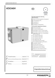
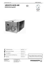
![3003415_ins_vex270hx_de.pdf [Download] - exhausto.de](https://img.yumpu.com/8086300/1/184x260/3003415-ins-vex270hx-depdf-download-exhaustode.jpg?quality=85)