A75 Cairntop to Barlae Dual Carriageway, Dumfries & Galloway ...
A75 Cairntop to Barlae Dual Carriageway, Dumfries & Galloway ...
A75 Cairntop to Barlae Dual Carriageway, Dumfries & Galloway ...

Create successful ePaper yourself
Turn your PDF publications into a flip-book with our unique Google optimized e-Paper software.
�<br />
�<br />
<strong>A75</strong> <strong>Cairn<strong>to</strong>p</strong> <strong>to</strong> <strong>Barlae</strong> <strong>Dual</strong> <strong>Carriageway</strong>,<br />
<strong>Dumfries</strong> & <strong>Galloway</strong><br />
Archaeological Evaluation<br />
Data Structure Report No. 1659
CFA ARCHAEOLOGY LTD<br />
The Old Engine House<br />
Eskmills Business Park<br />
Musselburgh<br />
East Lothian<br />
EH21 7PQ<br />
Tel: 0131 273 4380<br />
Fax: 0131 273 4381<br />
email: info@cfa-archaeology.co.uk<br />
web: www.cfa-archaeology.co.uk<br />
Author Ian Suddaby MA FSA Scot MIfA<br />
Illustra<strong>to</strong>r Leanne Whitelaw BSc MAAIS<br />
Edi<strong>to</strong>r Melanie Johnson MA PhD FSA Scot MIfA<br />
Commissioned by His<strong>to</strong>ric Scotland on behalf of Transport Scotland<br />
Date issued September 2009<br />
Version 0<br />
OASIS Reference cfaarcha1-64182<br />
Planning Application No -<br />
Grid Ref NX 252 592 <strong>to</strong> NX 274 602<br />
This document has been prepared in accordance with CFA Archaeology Ltd<br />
standard operating procedures.<br />
<strong>A75</strong> <strong>Cairn<strong>to</strong>p</strong> <strong>to</strong> <strong>Barlae</strong> <strong>Dual</strong> <strong>Carriageway</strong>,<br />
<strong>Dumfries</strong> & <strong>Galloway</strong><br />
Archaeological Evaluation<br />
Data Structure Report No. 1659
CONTENTS<br />
1. Introduction 3<br />
2. Working Methods 4<br />
3. Field-by-Field Summary of Trenching Results 5<br />
4. Conclusions and Discussion 10<br />
5. Bibliography 12<br />
Appendices<br />
1. Summary of Evaluation Trenches 13<br />
2. Context Register 15<br />
3. Pho<strong>to</strong>graph Register 16<br />
4. Drawings Register 23<br />
5. Samples Register 23<br />
Illustrations (bound at rear)<br />
Figs. 1-3 Road layout drawings showing trial trench and feature locations, access<br />
points and constraints<br />
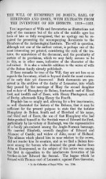
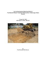
Fig. 4 View of the burnt mound location from the south on Dirlaughlin Hill<br />
Fig. 5 Trench 45 after overnight rain<br />
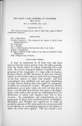
Fig. 6 Trench 45, Plan of the burnt mound (4501-2)<br />
Fig. 7 Trench 45, North <strong>to</strong> South section showing the burnt mound and peat<br />
profile <strong>to</strong> the south<br />
Fig. 8 Burnt s<strong>to</strong>ne lens (4503) mid-way up peat section <strong>to</strong> south of burnt mound<br />
Fig. 9 Test trench in<strong>to</strong> the burnt mound showing the s<strong>to</strong>nes (4501) in section<br />
Fig. 10 Trench 10 in Field 7 looking east<br />
Fig. 11 Surface field clearance s<strong>to</strong>nes (1401) in Trench 14 prior <strong>to</strong> excavation<br />
Fig. 12 Looking West over backfilled trenches in Field 8 with the boggy Field 7<br />
in the distance<br />
Fig. 13 Ditch (3801) in section from the north<br />
<strong>A75</strong>B/0/1659 2 CFA
1. INTRODUCTION<br />
1.1 This report provides the results of an archaeological evaluation within the<br />
corridor of the forthcoming <strong>A75</strong> <strong>Cairn<strong>to</strong>p</strong> <strong>to</strong> <strong>Barlae</strong> <strong>Dual</strong> <strong>Carriageway</strong>,<br />
<strong>Dumfries</strong> & <strong>Galloway</strong> (Figs. 1-3, NGR NX 252 592 <strong>to</strong> NX 274 602). It has<br />
been produced by CFA Archaeology Ltd (CFA) for His<strong>to</strong>ric Scotland on<br />
behalf of Transport Scotland.<br />
1.2 The parts of the road corridor included in the evaluation are shown in yellow<br />
and consist of areas of improved pasture on drumlins and areas of peat bog<br />
within the inter-drumlin basins. These range in height from 85m <strong>to</strong> 100m OD.<br />
1.3 The area’s archaeological potential and the detailed assessment leading up <strong>to</strong><br />
the evaluation are detailed in the Project Design (Johnson & Cressey 2009)<br />
and these details are not repeated here.<br />
1.4 The maps used <strong>to</strong> compile this document are:<br />
� Archaeological Investigation Locations 716500/ARCH/050-053<br />
� Ground Investigation Locations, Service Information and Proposed<br />
Alignment 716500/P/I/300-302<br />
� Proposed Additional Ground Investigation Explora<strong>to</strong>ry Hole Locations<br />
716528/AW/GI/001<br />
<strong>A75</strong>B/0/1659 3 CFA
2. WORKING METHODS<br />
2.1 CFA Archaeology Ltd follows the Institute for Archaeologists’ Code of<br />
Conduct, Standards and Guidance for Archaeological Watching Briefs (IfA<br />
2008a, 2008b, 2008c).<br />
2.2 The methodology in terms of trench setting out, overburden removal,<br />
evaluation, recording and sampling followed that in the Project Design<br />
(Johnson & Cressey 2009, Section 4). All work <strong>to</strong>ok place within the<br />
Compulsory Purchase Order (CPO) corridor. Where the location of utility<br />
services differed from that show on the road layout drawings, the actual route<br />
of these services was recorded by MobileMapper DGPS.<br />
2.3 Field numbers correspond with those outlined in the Project Design.<br />
2.4 Regular contact was maintained with the contrac<strong>to</strong>rs carrying out further SI<br />
works concurrently with the evaluation. Site visits were undertaken by Tony<br />
Topping of <strong>Dumfries</strong> & <strong>Galloway</strong> Council.<br />
<strong>A75</strong>B/0/1659 4 CFA
3. FIELD-BY-FIELD SUMMARY OF TRENCHING RESULTS<br />
3.1 General<br />
3.1.1 Table 1 illustrates the coverage, both actual and anticipated, that was achieved<br />
in each of the fields. The trenches are individually summarised in Appendix 1.<br />
Field Trenches Trenching coverage<br />
Actual [Anticipated] (m²)<br />
1 45, 46 110 [110]<br />
2 2A-2D 286 [250]<br />
3 None None<br />
4 4A-4P 1131 [1100]<br />
5 None None<br />
6 1 68 [110]<br />
7 2-13 670 [500]<br />
8 14-34 1214 [1400]<br />
9 9A-9O 770 [750]<br />
10 35-44 702 [700]<br />
Total 4951 [4920]<br />
Table 1: Evaluation Coverage per Field<br />
3.1.2 Surface deposits were varied, with 0.2m-0.4m of brown silty <strong>to</strong>psoil being<br />
present on the drumlins and peat with a depth of up <strong>to</strong> 2m was recorded in the<br />
trenches excavated in the inter-drumlin basins. The natural subsoil consisted in<br />
general of a s<strong>to</strong>ny, silty till. Very occasional sherds of 19 th and 20 th century<br />
pottery were observed within the <strong>to</strong>psoil and these were confined <strong>to</strong> trenches<br />
adjacent <strong>to</strong> the railway line.<br />
3.1.3 Land drains were identified solely in Field 4.<br />
3.1.4 In the following text, numbers in bold and parentheses refer <strong>to</strong> contexts (the<br />
standard unit of record in archaeological practice), a list of which is contained<br />
in Appendix 2. A summary of the trenching results is provided in Appendix 1.<br />
Other site records, consisting of the pho<strong>to</strong>graph, drawing and sample registers<br />
form Appendices 3-5.<br />
3.1.5 Two teams of archaeologists were working on site and there are therefore two<br />
trench numbering systems <strong>to</strong> reflect this. Team 1 evaluated Fields 1, 6, 7, 8<br />
and 10 and trench numbers run numerically from 1-46. Team 2 evaluated<br />
Fields 2, 4 and 9 and trench numbers in those fields are alphanumeric,<br />
prefixed with the field number and suffixed with a letter. These are listed in<br />
Appendix 1, showing the concordance between trench numbers and field<br />
numbers.<br />
3.2 Field 1 (Fig. 1)<br />
3.2.1 This field contained dense trees in the western end, and the eastern end lies<br />
under a former alignment of the <strong>A75</strong>. The only accessible part of the field for<br />
trial trenching lay <strong>to</strong> either side of an overhead power line, where very wet<br />
conditions were encountered, with up <strong>to</strong> 0.1m of surface water being present.<br />
The reasons for this waterlogging are illustrated in Fig. 4, which shows the<br />
<strong>A75</strong>B/0/1659 5 CFA
evaluation area from Dirlaughlin Hill <strong>to</strong> the south. Water drains from a<br />
shallow valley <strong>to</strong> the north of the <strong>A75</strong> and <strong>to</strong> the east of Knockishee Farm,<br />
under the <strong>A75</strong> and then pools below the overhead power lines due <strong>to</strong> an open<br />
ditched drain <strong>to</strong> the south having become blocked by peat. Flooding of Trench<br />
45 occurred overnight during heavy rain (Fig. 5).<br />
3.2.2 Two trenches (Trenches 45-6, Fig. 1) were excavated. Trench 46, in relatively<br />
dry ground <strong>to</strong> the west of the overhead power cables but accessible only over<br />
bog mats, revealed no archaeological remains.<br />
3.2.3 Trench 45, <strong>to</strong> the east of the overhead power cables revealed two plastic water<br />
pipes (4504, 4506) in the western end and a deposit of possible burnt mound<br />
material (4501-2) <strong>to</strong> the east. The trench was then extended (Fig. 6) <strong>to</strong> the east,<br />
up <strong>to</strong> an overgrown hedge alongside a former alignment of the <strong>A75</strong>.<br />
Telecommunications cables lie within this area. Two machine trenches were<br />
excavated <strong>to</strong> the south up <strong>to</strong> the boundary of the CPO area. Three hand<br />
excavated test-pits (TP1-3) were excavated <strong>to</strong> the north.<br />
3.2.4 The saturated <strong>to</strong>psoil (001) had a depth of 0.2m-0.3m. Below a similar depth<br />
of drier <strong>to</strong>psoil in the eastern end of the trench, the exposed burnt mound<br />
material (4501-2, Fig. 6) measured 15m east <strong>to</strong> west and 7.5m north <strong>to</strong> south.<br />
Two deposits were evident in plan, both containing discoloured and degrading<br />
greywacke s<strong>to</strong>nes of uniform size. The majority consisted of broken s<strong>to</strong>nes<br />
within a peaty matrix (4501) but several patches of similar s<strong>to</strong>nes within a<br />
black silty matrix (4502) were recorded. Both were penetrated by modern<br />
roots. An intermittent lens of eroded burnt mound material (4503) was<br />
recorded trailing off <strong>to</strong> the south.<br />
3.2.5 A section at the western side (Figs. 7-8) revealed the mound material had a<br />
depth of 0.3m. A machine excavated trench <strong>to</strong> the south (Fig. 7), up <strong>to</strong> the<br />
CPO boundary, revealed that the natural subsoil dipped steeply and that peat<br />
up <strong>to</strong> 1m thick was present at a distance of 6m <strong>to</strong> the south of the burnt<br />
mound. A basal deposit of mid-brown poorly humified peat (4509) with a<br />
depth of 0.3m underlay an intermittent lens of eroded burnt mound material<br />
(4503), with 0.6m of light-brown poorly humified peat (4508) above. Modern<br />
roots were frequent in the upper part of the profile but infrequent in the lower.<br />
To the east, a second machine sondage up <strong>to</strong> the CPO boundary revealed a<br />
similar depositional sequence with a <strong>to</strong>tal depth of 0.7m maximum.<br />
3.2.6 Three hand excavated test-pits (each 1m²) <strong>to</strong> the north of the trench revealed<br />
no archaeological remains. No finds were recovered.<br />
3.3 Field 2 (Fig. 1)<br />
3.3.1 Ground cover consisted of long grass and bracken with stands of small trees<br />
and shrubs, more dense at the western end.<br />
3.3.2 Four trenches (Trenches 2A-D, Fig. 1) were excavated in this field. The<br />
heavily root-affected <strong>to</strong>psoil (001) varied from 0.25m <strong>to</strong> 0.45m in depth and it<br />
<strong>A75</strong>B/0/1659 6 CFA
overlay a creamy orange clay-silt natural subsoil (003). No archaeological<br />
remains were present.<br />
3.4 Field 4 (Fig. 1)<br />
3.4.1 This majority of the field occupies the south-western slopes of Knock Orr and<br />
is mainly covered in short grass. A modern quarry has been excavated close <strong>to</strong><br />
the layby. The more level area adjacent <strong>to</strong> and <strong>to</strong> the east of the layby is wetter<br />
and contains grass and reeds.<br />
3.4.2 Sixteen trenches (Trenches 4A-P, Fig. 1) were excavated. The <strong>to</strong>psoil (001)<br />
varied from 0.15m up <strong>to</strong> 0.55m and it overlay subsoil (003) consisting of<br />
either a soft orange s<strong>to</strong>ny silt or a more compact grey s<strong>to</strong>ny silt . Both<br />
sediments were considered <strong>to</strong> be natural, with the orange (oxidised) sediments<br />
having formed either on the better drained slopes or over areas of softer (better<br />
drained) grey subsoil. These sediments are likely <strong>to</strong> be the result of natural soil<br />
processes. This sequence of sediments was also recorded in Field 8.<br />
3.4.3 Linear field drains (403, 405) were recorded in Trenches 4D and 4I and these<br />
were filled with small cobbles. A cast iron pipe (407) was also recorded in<br />
Trench 4I. No other features were present and no finds were recovered.<br />
3.5 Field 6 (Fig. 2)<br />
3.5.1 The area available for evaluation was confined <strong>to</strong> the eastern end of the field<br />
where a small area of long grass and bracken was present.<br />
3.5.2 An initial trench (Trench 1, Fig. 2) revealed that the water main, which was<br />
recorded on the utility plans as passing through the gate between Fields 6 and<br />
7, in fact ran through the evaluation area in Field 6. Trench 1 recorded its cut<br />
(101) under 0.15m of <strong>to</strong>psoil (001) and no further trenches were excavated.<br />
The natural subsoil (003) was orange s<strong>to</strong>ny silt and creamy-blue s<strong>to</strong>ny silt; the<br />
latter was recorded under deeper peat deposits <strong>to</strong> the west. No other features<br />
were present and no finds were recovered.<br />
3.6 Field 7 (Fig. 2)<br />
3.6.1 The ground available for evaluation consisted of a combination of long grass<br />
and reeds, with bedrock outcrops in the area of Trenches 5-7. The field was<br />
increasingly wet and boggy <strong>to</strong>wards the east side. As the alignment of the<br />
water main in Field 6 had been established through trenching, a trench (Trench<br />
3) was able <strong>to</strong> be positioned immediately <strong>to</strong> the east of the field wall<br />
separating Fields 6 and 7. An open culvert <strong>to</strong> the east of the field was avoided.<br />
3.6.2 Twelve trenches (Trenches 2-13, Fig. 2) were excavated. Trenches 3, 5-7 and<br />
13 contained between 0.1m and 0.3m of <strong>to</strong>psoil (001) over either bedrock or<br />
natural subsoil (003), with the remaining trenches containing between 0.5m<br />
and 2m of peat over a creamy-blue till (eg Trench 10, Fig. 10). No<br />
archaeological remains were present.<br />
<strong>A75</strong>B/0/1659 7 CFA
3.7 Field 8 (Fig. 2)<br />
3.7.1 The area available for evaluation <strong>to</strong> the north of the railway cutting consisted<br />
of short grass, with bracken and extensive spreads of cleared s<strong>to</strong>nes (Fig. 11).<br />
Wetter ground was present in the area of Trench 15. Trenches 16-34 were<br />
sited on the higher ground of the drumlin <strong>to</strong> the north of Blairderry Bridge.<br />
Between these trenches and the railway cutting was an area of level ground<br />
containing the stumps of substantial trees and deposits of dumped s<strong>to</strong>nes<br />
(presumably field clearance); no trenches were excavated in this area. Fig. 12<br />
shows the view west from Blairderry Bridge.<br />
3.7.2 Twenty-one trenches (Trenches 14-34, Fig. 2) were excavated. Aside from<br />
Trench 15, the deposits in this field consisted of a thin <strong>to</strong>psoil (001), which<br />
overlay natural (003) consisting of either a soft orange s<strong>to</strong>ny silt or a more<br />
compact grey s<strong>to</strong>ny silt. As in Field 4, both deposits were considered <strong>to</strong> be<br />
natural, with the orange (oxidised) sediments having formed either on the<br />
flanks of the drumlin or over areas of softer (better drained) grey till. In<br />
several cases, poorly defined deposits of dark brown silt with occasional<br />
charcoal flecks were present within the orange sediments and a sample of<br />
these was recovered from Trench 32 (3201) where they were most extensive.<br />
These sediments are likely <strong>to</strong> be the result of natural soil processes.<br />
3.7.3 In Trench 14, an extensive spread of field clearance s<strong>to</strong>nes (1401) was<br />
recorded over the entire area of the trench. These were cut by a linear ditch<br />
(1403) with a width of 1.2m and a depth of 0.3m. Ditch 1403 contained a<br />
sterile grey fill (1404), and lumps of redeposited subsoil (1405) were present<br />
between 2m and 4m <strong>to</strong> the west, suggesting machine excavation of the feature.<br />
No finds were recovered. In Trench 15, a thin basal deposit of silty peat (1503)<br />
was overlain by a layer of grey redeposited subsoil (1502) and this underlay a<br />
surface deposit of peat (1500) contained large quantities of s<strong>to</strong>nes (1501). Two<br />
sherds of white glazed ceramic lay within <strong>to</strong>psoil <strong>to</strong> the north of the railway<br />
cutting. No other finds were recovered.<br />
3.8 Field 9 (Fig. 3)<br />
3.8.1 Field 9 lies at the northern edge of the Barfad drumlin and most of the area<br />
consists of short grass. An area of reeds lies adjacent <strong>to</strong> the animal pens at the<br />
junction between the Gass Road and the <strong>A75</strong>. Trenches were not excavated<br />
across the access point in<strong>to</strong> the field as this was in use by the farmer. To the<br />
west, the western end of Trenches 9k, 9l and 9m extended in<strong>to</strong> a boggy area<br />
adjacent <strong>to</strong> the Toll Bar Burn. Field clearance s<strong>to</strong>nes were noted at the edge of<br />
the drumlin on the west.<br />
3.8.2 Fifteen trenches (Trenches 9A-O, Fig. 3) were excavated. The <strong>to</strong>psoil (001)<br />
varied in depth from 0.25m <strong>to</strong> 0.4m and it overlay a grey till (003). No<br />
archaeological remains were present.<br />
<strong>A75</strong>B/0/1659 8 CFA
3.9 Field 10 (Fig. 3)<br />
3.9.1 The area available for evaluation was bounded <strong>to</strong> the north by the diverted<br />
Toll Bar Burn and <strong>to</strong> the south by the railway alignment and the <strong>A75</strong>. It was<br />
covered with a shallow waterlogged peat under grass, bog myrtle and reeds.<br />
The south-eastern part of the field has been extensively disturbed by machine<br />
movements associated with the diverting of the Toll Bar Burn. A north <strong>to</strong><br />
south aligned water pipe, shown on the utility plans as crossing the western<br />
part of the field, is instead visible on the ground west of its indicated position.<br />
One trench was excavated between the railway track bed and its northern<br />
boundary fence in the only portion not affected by trees.<br />
3.9.2 Ten trenches (Trenches 35-44, Fig. 3) were excavated. In the least disturbed<br />
ground <strong>to</strong> the west, <strong>to</strong>psoil (001) with a depth of 0.25m overlay deposits of<br />
blue-grey till and fractured bedrock (003). To the east, much of the surface<br />
deposits were recently disturbed and consisted of saturated peat.<br />
3.9.3 Trench 38 was located in a narrow undisturbed zone between the water main<br />
and the existing <strong>A75</strong>. Over most of its length, a thin <strong>to</strong>psoil (001) overlay<br />
boulders and bedrock but at the western end deposits of saturated blue-grey till<br />
(003) were encountered. At this location, a 0.25m deep deposit of peat<br />
underlay the <strong>to</strong>psoil and this sealed a linear ditch (3801, Fig. 13) with a width<br />
of 0.9m and depth of 0.25m, aligned approximately NW-SE. Cutting the till, it<br />
was filled with a poorly humified peat (3802) within which were small<br />
quantities of charcoal, concentrated on the western side. This feature was less<br />
substantial in the opposing section.<br />
<strong>A75</strong>B/0/1659 9 CFA
4. DISCUSSION AND CONCLUSIONS<br />
4.1 Trial trenches covering 4951m 2 out of an available c.25,000m² (19.8%) were<br />
excavated within the available areas of the <strong>A75</strong> <strong>Cairn<strong>to</strong>p</strong> <strong>to</strong> <strong>Barlae</strong> <strong>Dual</strong><br />
<strong>Carriageway</strong>. Much of this consisted of semi-improved pasture land on the<br />
drumlins, with some trenching taking place in the shallower peat of interdrumlin<br />
basins. There is nevertheless an almost complete absence of evidence<br />
for actual land improvement by way of land drainage for example, though<br />
evidence for field clearance was recorded in Fields 8 and 9. The<br />
archaeological potential of the area was expected <strong>to</strong> be low and this was<br />
supported by the evaluation.<br />
4.2 The fieldwork revealed two previously unknown sites of archaeological<br />
significance, that of a possible burnt mound (Trench 45) and a ditch (Trench<br />
38). Mitigation proposals are detailed in Section 5 below. Other remains,<br />
consisting of modern ditches and spreads of field clearance s<strong>to</strong>ne, are not<br />
considered <strong>to</strong> be of archaeological interest.<br />
Burnt Mound<br />
4.3 A probable burnt mound was recorded in Trench 45 near Derskelpin in Field<br />
1. Trial trenching and test-pitting indicate that it measures c.15m by 8m and<br />
consists of deposits of discoloured and degraded s<strong>to</strong>ne within a peaty matrix<br />
with some patches of black silt recorded. The mound lies in a pocket of<br />
undisturbed ground between telecommunications cables, a water pipe, the<br />
field boundary and the former alignment of the <strong>A75</strong>. The area is prone <strong>to</strong><br />
waterlogging due <strong>to</strong> its <strong>to</strong>pographic location, and so there is potential for the<br />
survival of organic material.<br />
4.4 Burnt mounds are a feature of the East Rhins of <strong>Galloway</strong> (Russell-White<br />
1990), an area defined on its eastern side by the Moors of <strong>Galloway</strong>, on which<br />
the <strong>A75</strong> <strong>Cairn<strong>to</strong>p</strong> <strong>to</strong> <strong>Barlae</strong> <strong>Dual</strong> <strong>Carriageway</strong> is located. They have also been<br />
identified more recently during field survey around Knock Fell (Pickin 2000,<br />
22). A reasonably comprehensive list of the burnt mounds in <strong>Dumfries</strong> and<br />
<strong>Galloway</strong> is online (CAST 2001) at http://www.cast.org.uk/dag.htm. The<br />
National Monuments Record of Scotland and His<strong>to</strong>ric Scotland’s ‘Pastmap’<br />
database, at http://jura.rcahms.gov.uk/PASTMAP/Map, contains more detailed<br />
information on these sites.<br />
4.5 Russell-White (1990, 71-2) describes the 1987 excavations at Dervaird burnt<br />
mound (NGR: NX 224 582), a site also excavated in advance of <strong>A75</strong> road<br />
improvements, which is 3km SW of that found in the current work. The<br />
Dervaird burnt mound was kidney shaped, measuring 16m by 8m and was<br />
located next <strong>to</strong> a small stream. A single cooking pit, partly s<strong>to</strong>ne lined and<br />
with an oak floor, was recorded between the ‘horns’ of the mound. C14 dates<br />
from charcoal and the oak floor itself gave determinations of 1530-1300 cal<br />
BC (GU-2331) and 1620-1400 cal BC (GU-2330). Other burnt mounds in the<br />
area have been dated <strong>to</strong> the Later Bronze Age and <strong>to</strong> the medieval periods<br />
(ibid).<br />
<strong>A75</strong>B/0/1659 10 CFA
4.6 Although both numerous and geographically widespread, the function of burnt<br />
mounds is still a hotly debated <strong>to</strong>pic. Seasonal or ritual communal cooking is a<br />
favoured interpretation (O’Kelly 1954), but other ideas include saunas<br />
(Barfield & Hodder 1987) and even breweries (Peterkin 2007). Recent work<br />
stresses the potential for evidence of woodland clearance and the<br />
intensity/duration of human activity on these sites, information which may be<br />
available from detailed field sampling and labora<strong>to</strong>ry analysis, as well as the<br />
potential for locating nearby contemporary/sequential settlement. In Scotland,<br />
structures are associated with burnt mounds in the Northern (Hedges 1975)<br />
and Western (Armit & Braby 2002) Isles, but so far not in the south-west.<br />
4.7 The Derskelpin burnt mound compares well in size with the nearby example<br />
excavated at Dervaird (Russell-White 1990). The wet ground conditions at<br />
Derskelpin may be conducive <strong>to</strong> the survival of timber features and other<br />
organic material.<br />
Ditch<br />
4.8 The only other feature of any antiquity may be the ditch in Trench 38. Sealed<br />
beneath 0.25m of peat and containing charcoal, this feature has in all<br />
probability been cut <strong>to</strong> the north by the water main and been disturbed by<br />
work associated with the diversion of the Toll Bar Burn. To the south lies a<br />
modern roadside drain and the existing <strong>A75</strong>. The age of this ditch is unclear<br />
and would be dependent on the rapidity of peat growth in this area; no<br />
dateable finds were recovered. It is possibly a drainage ditch which has<br />
infilled with peat growth due <strong>to</strong> the waterlogged conditions.<br />
Further Work<br />
4.9 A mitigation strategy is provided under separate cover (CFA Report no.<br />
1659.1).<br />
4.10 A Discovery and Excavation in Scotland Entry will be submitted for<br />
publication following completion of all mitigation and the project will be<br />
recorded via the OASIS pro<strong>to</strong>col.<br />
<strong>A75</strong>B/0/1659 11 CFA
5. BIBLIOGRAPHY<br />
Armit, I & Braby, A 2002 ‘Excavation of a burnt mound and associated structures at<br />
Ceann nan Clachan, North Uist’, Proc Soc Antiq Scot, 132 (2002), 229–58<br />
Barfield, L & Hodder, M 1987 ‘Burnt mounds as saunas and the prehis<strong>to</strong>ry of<br />
bathing’, Antiquity, 61, 370–9<br />
Buckley, V (ed) 1990 Burnt Offerings: International Contributions <strong>to</strong> Burnt Mound<br />
Archaeology. Wordwell, Dublin<br />
CAST 2001 ‘<strong>Dumfries</strong> & <strong>Galloway</strong>: Summary of places of interest’<br />
http://www.cast.org.uk/dag.htm<br />
Cressey, M & Strachan, R 2003 ‘The excavation of two burnt mounds and a wooden<br />
trough near Beechwood Farm, Inshes, Inverness, 1999’, Proc Soc Antiq Scot,<br />
133 (2003), 191-203<br />
Hedges, J 1975 ‘Excavation of two Orcadian burnt mounds at Liddle and Beaquoy’,<br />
Proc Soc Antiq Scot, 106 (1974–5), 39–98<br />
Johnson, M & Cressey, M 2009 <strong>A75</strong> ‘<strong>Cairn<strong>to</strong>p</strong> <strong>to</strong> <strong>Barlae</strong> <strong>Dual</strong> <strong>Carriageway</strong>, <strong>Dumfries</strong><br />
& <strong>Galloway</strong>, Project Design for Programme of Archaeological Works’. CFA<br />
Archaeology Ltd. Unpublished Report No. 1655. Commissioned by His<strong>to</strong>ric<br />
Scotland on behalf of Transport Scotland<br />
O’Kelly, M J 1954 ‘Excavation and experiments in ancient Irish cooking sites’, J R<br />
Soc Antiq Ireland, 84, 105-55<br />
National Monuments Record of Scotland and His<strong>to</strong>ric Scotland’s ‘Pastmap’<br />
http://jura.rcahms.gov.uk/PASTMAP/Map<br />
Neighbour, T & Johnson, M 2005 ‘A Bronze Age burnt mound in lowland Cumbria:<br />
excavations at Garlands Hospital, Carlisle, 1997’, Trans Cumberland<br />
Westmorland Antiq & Archaeol Soc, V (2005), 11–23<br />
Peterkin, T 2007 ‘Bronze Age brew proves a vintage ale’, Sunday Telegraph,<br />
13/08/2007<br />
http://www.telegraph.co.uk/science/science-news/3303248/Bronze-Age-brewproves-a-vintage-ale.html<br />
Pickin, J 2000, Knock Fell, Survey, DES 2000, 22<br />
Russell-White, C J 1990 ‘The East Rhins of <strong>Galloway</strong>’ in Buckley, V (ed) 70-6<br />
<strong>A75</strong>B/0/1659 12 CFA
APPENDIX 1: SUMMARY OF EVALUATION TRENCHES<br />
Trench<br />
No.<br />
Field Length<br />
(m)<br />
Width<br />
(m)<br />
Depth of<br />
overburden<br />
min / max (m)<br />
Comments<br />
1 6 34 2 0.15 / 1.4 Grass/Bracken, Reeds. Water main (101)<br />
2 7 51 2 0.2 / 1.3 Peat<br />
3 7 7 6 0.2 Grass<br />
4 7 50 2 0.2 / 1.1 Peat<br />
5 7 11 2 0.2 Grass & Bedrock<br />
6 7 27 2 0.2 Grass & Bedrock<br />
7 7 27 2 0.1 / 0.7 Grass, Peat & Bedrock<br />
8 7 30 2 0.25 / 0.5 Peat<br />
9 7 28 2 0.3 / 0.5 Peat<br />
10 7 20 2 0.5 / 1.8 Peat<br />
11 7 26 2 0.45 / 1.7 Peat<br />
12 7 26 2 0.4 / 1.7 Peat<br />
13 7 9 4 0.3 Grass & Bracken<br />
14 8 47 3.4 0.3 / 0.5 Grass & Bracken. Field Clearance S<strong>to</strong>nes<br />
(1401). Linear Ditch (1403)<br />
15 8 34 3 0.5 / 0.65 Made Ground (1502) under and over peat.<br />
Field Clearance S<strong>to</strong>nes (1501)<br />
16 8 32 2 0.25 / 0.35 Grass<br />
17 8 28 2 0.25 / 0.35 Grass<br />
18 8 15 2 0.25 Grass<br />
19 8 8 6.5 0.25 Grass<br />
20 8 30 2 0.25 Grass<br />
21 8 37 2 0.25 Grass<br />
22 8 17 2 0.25 Grass<br />
23 8 31 2 0.25 Grass<br />
24 8 16 2 0.25 Grass<br />
25 8 36 2 0.25 Grass<br />
26 8 27 2 0.25 Grass<br />
27 8 22 2 0.25 Grass<br />
28 8 8 2 0.25 Grass<br />
29 8 27 2 0.25 Grass<br />
30 8 14 2 0.25 Grass<br />
31 8 39 2 0.25 Grass<br />
32 8 32 2 0.25 Grass<br />
33 8 23 2 0.25 Grass<br />
34 8 16 2 0.25 Grass<br />
35 10 25 2 0.3 Grass, Reeds, Bog Myrtle<br />
36 10 51 2 0.3 Grass, Reeds, Bog Myrtle<br />
37 10 52 2 0.35 / 0.45 Grass, Reeds, Bog Myrtle<br />
38 10 37 2 0.2 / 0.6 Grass, Reeds. Linear Ditch (3801)<br />
39 10 31 2 0.3 / 0.45 Reeds, Bog Myrtle<br />
40 10 54 2 0.3 Reeds, Bog Myrtle<br />
41 10 36 2 0.3 Reeds, Bog Myrtle<br />
42 10 18 2 0.25 Reeds, Bog Myrtle<br />
43 10 28 2 0.25 Grass, Reeds, Bog Myrtle<br />
44 10 19 2 0.4 Grass, Reeds, Bog Myrtle, Brushwood<br />
45 1 30 2-4 0.2 / 0.5 Grass, Reeds. Burnt Mound (4501-3). Two<br />
Water Pipes (4504, 4506)<br />
46 1 18 2 0.3 Grass, Reeds<br />
2A 2 59 1.8 0.25 / 0.4 Grass, Bracken<br />
2B 2 45 1.8 0.4 / 0.45 Grass, Bracken<br />
2C 2 40 1.8 0.3 / 0.35 Grass, Bracken<br />
2D 2 15 1.8 0.25 Grass, Bracken<br />
<strong>A75</strong>B/0/1659 13 CFA
Trench<br />
No.<br />
Field Length<br />
(m)<br />
Width<br />
(m)<br />
Depth of<br />
overburden<br />
min / max (m)<br />
Comments<br />
4A 4 40 1.8 0.15 Grass<br />
4B 4 39 1.8 0.15 Grass<br />
4C 4 36 1.8 0.15 Grass<br />
4D 4 50 1.8 0.3 / 0.35 Grass, Field Drain (403)<br />
4E 4 49 1.8 0.3 Grass<br />
4F 4 53 1.8 0.3 Grass<br />
4G 4 50 1.8 0.4 Grass<br />
4H 4 30 1.8 0.5 Grass<br />
4I 4 48 1.8 0.25 / 0.55 Grass, Field Drain (405), Water Pipe (407)<br />
4J 4 56 1.8 0.4 Grass<br />
4K 4 49 1.8 0.25 / 0.4 Grass<br />
4L 4 50 1.8 0.25 Grass<br />
4M 4 30 1.8 0.35 Grass<br />
4N 4 5 1.8 0.3 Grass<br />
4O 4 30 1.8 0.3 / 0.35 Grass<br />
4P 4 15 1.8 0.15 Grass<br />
9A 9 24 1.8 0.25 Grass<br />
9B 9 28 1.8 0.3 Grass<br />
9C 9 34 1.8 0.35 Grass<br />
9D 9 24 1.8 0.35 Grass<br />
9E 9 28 1.8 0.25 / 0.4 Grass<br />
9F 9 24 1.8 0.3 Grass<br />
9G 9 20 1.8 0.3 Grass<br />
9H 9 23 1.8 0.3 Grass<br />
9I 9 24 1.8 0.25 / 0.3 Grass<br />
9J 9 30 1.8 0.25 / 0.35 Grass<br />
9K 9 42 1.8 0.25 / 0.35 Grass<br />
9L 9 51 1.8 0.25 / 0.35 Grass<br />
9M 9 40 1.8 0.25 / 0.35 Grass<br />
9N 9 19 1.8 0.25 Grass<br />
9O 9 17 1.8 0.2 / 0.25 Grass<br />
<strong>A75</strong>B/0/1659 14 CFA
APPENDIX 2: CONTEXT REGISTER<br />
Context No. Trench/Area Fill of Type Description<br />
001 Topsoil<br />
002 Buried soils/peats<br />
003 Natural subsoil<br />
101 Trench 1 Cut Linear cut for water main<br />
102 Trench 1 101 Deposit Mixed fill over quarry dust<br />
1401 Trench 14 Deposit Field clearance s<strong>to</strong>nes over whole<br />
trench<br />
1402 Trench 14 Deposit Topsoil and matrix around s<strong>to</strong>nes at<br />
WSW end of trench<br />
1403 Trench 14 Cut Linear cut for ditch<br />
1404 Trench14 1403 Deposit Lumps of redeposited grey/orange clay<br />
silt natural subsoil<br />
1405 Trench 14 Deposit Lumps of redeposited grey/orange clay<br />
silt natural subsoil<br />
1406 Trench 14 Deposit Matrix around s<strong>to</strong>nes. Brown-grey clay<br />
silt<br />
1901 Trench 19 Cut Cut for borehole<br />
1902 Trench 19 Deposit Gravel, soil, ben<strong>to</strong>nite fill, and plastic<br />
pipe<br />
3201 Trench 32 Deposit Dark soil with charcoal flecks and dark<br />
red s<strong>to</strong>nes<br />
3801 Trench 38 Cut Linear cut for shallow ditch<br />
3802 Trench 38 3801 Deposit Peat with charcoal lumps<br />
4501 Trench 45 Deposit Burnt mound material with peat matrix<br />
4502 Trench 45 Deposit Burnt mound material with black<br />
matrix<br />
4503 Trench 45 Deposit Burnt mound material with lens, in S of<br />
trench<br />
4504 Trench 45 Cut Linear cut<br />
4505 Trench 45 4504 Deposit Wet soil and blue plastic water pipe<br />
4506 Trench 45 Cut Linear cut<br />
4507 Trench 45 4506 Deposit Wet soil and black plastic water pipe<br />
4508 Trench 45 Deposit Mid brown poorly humified peat<br />
4509 Trench 45 Deposit Light brown porly humified peat<br />
403 Trench 4D Cut Cut of narrow and shallow gully/field<br />
drain<br />
404 Trench 4D 403 Deposit Mid greyish brown sandy silt<br />
405 Trench 4I Natural subsoil<br />
406 Trench 4I Natural subsoil<br />
407 Trench 4I Cut Cut for cast-iron pipe {408}<br />
408 Trench 4I Cast-iron pipe in [407]<br />
409 Trench 4I 407 Deposit Re-deposited natural<br />
<strong>A75</strong>B/0/1659 15 CFA
APPENDIX 3: PHOTOGRAPH REGISTER<br />
SLR No. Digital No Contexts/description Taken From Conditions<br />
1 Access gate in<strong>to</strong> field 7 SE Sunny<br />
2 Access gate field 7 in<strong>to</strong> field 6 SE Sunny<br />
3 General view of above gates NE Sunny<br />
4 General view of trenches 1 & 2, field 6, pre-ex NE Sunny<br />
5 General view of field 7, pre-ex NW Sunny<br />
6 General view of field 7, pre-ex W Sunny<br />
7 General view of field 7, pre-ex SW Bright<br />
8 Trench 1 SSE facing section in peat, showing<br />
peat over bedrock. General<br />
SSE<br />
9 Trench 1 SSE facing section in peat, showing SSE<br />
peat over bedrock. Close-up<br />
10 Trench 1, general view WSW<br />
11 Trench 1, general view ENE<br />
12 Trench 1, deep peat area at SW end ENE Overcast<br />
13 Trench 1, backfilled ENE Dull<br />
14 Trench 2, WNW facing peat section WNW Dull<br />
15 Trench 2, excavated WSW Dull<br />
16 Trench 2, excavated ENE Dull<br />
17 Trench 3, general view WNW Dull<br />
18 Trench 3, excavated ENE Dull<br />
19 Trench 4, excavated WSW Dull<br />
20 Trench 4, peat section in mid trench WNW Dull<br />
21 Trench 4, excavated ENE Dull<br />
22-23 Area of trenches 5 & 6, pre-ex WNW Dull<br />
24 Trench 4, view of s<strong>to</strong>ny subsoil in trench base WSW Dull<br />
25 Trench 5, excavated WSW Dull<br />
26 Trench 5, excavated NNE Dull<br />
27 Trench 5, soil section, mid trench WNW Overcast<br />
28 Trench 6, excavated WSW Dull<br />
29 Trench 6, general view NW Dull<br />
30 Trench 6, excavated ENE Dull<br />
31 Trench 7, excavated S Dull<br />
32 Trench 7, excavated, general view, with W Dull<br />
trenches 8 & 9 beyond<br />
33 Trench 8, excavated, general view ENE Dull<br />
34 Trench 8, peat section at ENE end SE Dull<br />
35 Trench 8, general view of WSW end ENE Dull<br />
36 Trench 8, general view WSW Dull<br />
37 Trench 8, natural cup marks in bedrock Dull<br />
38 Trench 9, excavated, general view WSW Dull<br />
39 Trench 9, soil/peat section WNW Dull<br />
40 Trench 9, excavated, general view ENE Dull<br />
41 Trench 9, excavated, close-up ENE Dull<br />
42-43 Trench 10, excavated, ENE end ENE Dull<br />
44 Trench 10, section at ENE end WNW Dull<br />
45-48 Trench 10, excavated ENE Dull<br />
49-50 Trench 10, general view WSW Dull<br />
51 Trench 10, location in bog W Dull<br />
52 Trench 10, general view, with added water WSW Dull<br />
53-54 Trench 8, view of area NNW Dull<br />
55-56 Field 7, Bog mats used <strong>to</strong> cross culvert/drainage W<br />
ditch<br />
Overcast<br />
57-58 Trench 11, peat section at WSW end ENE Dull<br />
59 Trench 11, large log (2.2m x 0.3m) on spoil<br />
heap<br />
E<br />
<strong>A75</strong>B/0/1659 16 CFA
SLR No. Digital No Contexts/description Taken From Conditions<br />
60 Trench 11, excavated, general view ENE Dull<br />
61 Trench 11, peat section at ENE end NNW Dull<br />
62-64 Trench 12, peat section at WSW end NE Dull<br />
65 Trench 12, excavated ENE Dull<br />
66 Trench 12, peat section, mid trench NNW Overcast<br />
67 Trench 12, excavated WSW Dull<br />
68 Field 8, pre-ex WSW Overcast<br />
69-72 Access in<strong>to</strong> field 9 Overcast<br />
73-74 Fence access in<strong>to</strong> field 8 after bracken removed S Overcast<br />
75-76 Trench 13, excavated ENE Overcast<br />
77 Trench 14, pre-ex WSW Overcast<br />
78 Trench 14, patch of s<strong>to</strong>nes within trench area,<br />
pre-ex<br />
NNW Overcast<br />
79 Trench 14, possible rig and furrow at ENE end NNW Overcast<br />
80 Trench 14, working shot showing field<br />
clearance s<strong>to</strong>nes (1401)<br />
WSW Overcast<br />
81 Trench 14, ENE facing section showing field<br />
clearance s<strong>to</strong>nes (1401)<br />
ENE Overcast<br />
1-2 82 Trench 14, excavated, general view ENE Overcast<br />
3-4 83 Trench 14, excavated, view of s<strong>to</strong>nes (1401) W Overcast<br />
over subsoil at ENE end<br />
5-6 84 Trench 14, general views of section NE Overcast<br />
7-8 85 Trench 14, general views of section NNW Overcast<br />
9-10 86 Trench 14, ditch [1403] NNW Overcast<br />
11-12 87 Trench 14, ditch [1403], close-up NNW Overcast<br />
13-14 88 Trench 14, drawn section at WSW end ENE Overcast<br />
15-16 89-90 Trench 15, excavated, general view WSW Sunny<br />
17-18 91 Trench 15, excavated, general view ENE Sunny<br />
19-20 92 Trench 15, section 1 SSE Sunny<br />
21-22 93-94 Trench 15, section 2 NNW Shade<br />
23-24 95 Trench 15, section 3 SSE Sunny<br />
25-26 96-99 Trench 15, section 4 NNW Shade<br />
100-103 Trench 15, metal railway fence support and<br />
wire tensioner on modern fence line<br />
104 Trench 18, general view SW Sunny<br />
105 Trench 18, natural curvilinear feature W Sunny<br />
106 Trench 18, SE facing section SE Sunny<br />
107 Trenches 16, 17 & 18, general view WSW Sunny<br />
108 Trench 17, general view WSW Sunny<br />
109-110 Trench 17, section at WSW end SSE Sunny<br />
111 Trench 17, section at ENE end SSE Sunny<br />
112 Trench 17, general view ENE Sunny<br />
113 Trench 16, general view ENE Sunny<br />
114-115 Trench 16, section at ENE end SSE Sunny<br />
116 Trench 16, section at WSW end SSE Sunny<br />
117 Trench 16, general view WSW Sunny<br />
118-121 Site panorama including Field 9 trenches from NW - NE Sunny<br />
N of Field 8<br />
122-123 Field 9, from field 8 W Sunny<br />
124 Trench 20, section NW Overcast<br />
125 Trench 20, general view SW Overcast<br />
126 Trench 20, general view NE Overcast<br />
127 Trench 19, mottled patches of brown and black<br />
soil with charcoal flecks<br />
SSE Overcast<br />
128 Trench 19, mottled patches of brown and black<br />
soil with charcoal flecks<br />
WSW Overcast<br />
129 Trench 19, Pleizometer borehole with ben<strong>to</strong>nite W Overcast<br />
<strong>A75</strong>B/0/1659 17 CFA
SLR No. Digital No Contexts/description<br />
clay grouting and blue pipe (1901-2)<br />
Taken From Conditions<br />
130 Trenches 16 & 17, with Lankelma cone<br />
penetration rig beyond<br />
E Overcast<br />
131-132 Trench 19, general view SSE Bright<br />
133 Trench 21, general view SSE Sunny<br />
134 Percussion rig operating at SW end of trench 20 SW<br />
135 Trench 21, section, med trench WSW Sunny<br />
136 Trench 21, general view, mid trench S Sunny<br />
137 Trench 21, general view NNW Sunny<br />
138 Trench 22, orange patch in mid trench, with<br />
water filled section<br />
S Overcast<br />
139 Trench 22, general view SE Bright<br />
140 Trench 23, general view NW Sunny<br />
141 Trench 23, general view NE Sunny<br />
142 Trench 23, general view of subsoil surface SE Sunny<br />
143 Trench 24, orange-brown s<strong>to</strong>ny patch prior <strong>to</strong><br />
removal<br />
S Bright<br />
144 Trench 24, orange-brown s<strong>to</strong>ny patch prior <strong>to</strong><br />
removal<br />
E Bright<br />
145 Trench 24, orange-brown s<strong>to</strong>ny patch almost<br />
removed<br />
E Bright<br />
146 Trench 24, orange-brown s<strong>to</strong>ny patch almost<br />
removed<br />
S Bright<br />
147-149 Trench 24, view of W facing section WNW - W Bright<br />
150 Trench 24, general view S Bright<br />
151 Trench 25, SSE facing section SSE Overcast<br />
152 Trench 25, general view WSW Overcast<br />
153 Trench 25, general view ENE Overcast<br />
154 Trench 27, general view WNW Overcast<br />
155 Trench 27, general view ESE Overcast<br />
156 Trench 26, general view ESE Overcast<br />
157 Trench 26, general view WNW Overcast<br />
158 Trench 28, general view NNW Bright<br />
159 Trench 28, ENE facing section NE Bright<br />
160 Trench 29, general view SSE Overcast<br />
161 Trench 29, general view NNW Overcast<br />
162 Trench 29, ENE facing section ENE Overcast<br />
163-164 Field 8, area of trenches 16 <strong>to</strong> 33 NW Overcast<br />
165 Field 8, area of trenches 16 <strong>to</strong> 33 W Overcast<br />
166 Trench 30, general view NNW Overcast<br />
167 Trench 30, close-up NNW Overcast<br />
168 Trench 30, general view SSE Overcast<br />
169-170 Trench 31, section at WSW end SSE Overcast<br />
171 Trench 31, general view WSW Overcast<br />
172 Trench 31, general view ENE Overcast<br />
173-177 Tree stumps and dumped boulders in area<br />
between fence and railway cutting<br />
178 Trench 32, patch of charcoal flecks in dark silty NW<br />
matrix (3201), close-up<br />
Overcast<br />
179 Trench 32, patch of charcoal flecks in dark silty NW<br />
matrix (3201), general<br />
Overcast<br />
180 Trench 32, view of area of (3201) after<br />
sampling<br />
E Wet<br />
181 Trench 32, general view SW Wet<br />
182 VOID<br />
183-184 Trench 32A, extension <strong>to</strong> NNW, area of (3201)<br />
in foreground<br />
SSE Wet<br />
<strong>A75</strong>B/0/1659 18 CFA
SLR No. Digital No Contexts/description Taken From Conditions<br />
185 Trench 33, general view SW Bright<br />
186-187 Trench 33, section at SW end NE Overcast<br />
188 Trench 34, general view WSW Bright<br />
189-190 Trench 34, section at WSW end ENE Bright<br />
191-192 Field 8, trenches 16 <strong>to</strong> 34, general view NW Overcast<br />
193-197 Field 8, general view of backfilled trenches N Overcast<br />
198-199 Local wildlife and conditions (Adder)<br />
200-201 Railway fence <strong>to</strong> W of Blairderry Bridge E Overcast<br />
202-204 Fence from railway in<strong>to</strong> field 8, repaired S Overcast<br />
205 Trench 35, general view W Dull<br />
206 Trench 35, general view E Dull<br />
207-208 Trench 35, section, mid-trench N Dull<br />
209 Trench 36, general view W Dull<br />
210 Trench 36, general view E Dull<br />
211 Trench 36, large boulders in base of trench<br />
212 Trench 36, section, mid-trench N Dull<br />
213-216 Field 10, general views<br />
217 Trench 37, pre-ex, showing prominent knoll NW Sunny<br />
218 Trench 37, pre-ex, showing prominent knoll N Sunny<br />
219 Trench 37, pre-ex, showing prominent knoll NE Sunny<br />
220 Trench 37, surface of bedrock knoll ENE Sunny<br />
221 Trench 37, knoll de-turfed, bedrock showing WSW Sunny<br />
222 Trench 37, surface of bedrock knoll ENE Sunny<br />
223 Trench 37, ENE side of bedrock knoll ENE Sunny<br />
224 Trench 37, general view ENE Sunny<br />
225-227 Trench 37, section at ENE end of trench Sunny<br />
228-230 Trench 37, section at WSW end of trench SSE Bright<br />
231 Trench 38, sondage at WSW end showing ditch NE<br />
[3801]<br />
Bright<br />
232-234 Trench 38, ditch [3801], NNW facing section, NNW Bright<br />
general and close-up<br />
235-236 Trench 38, SSE facing section ditch [3801] SSE Bright<br />
237 Trench 38, general view WSW Bright<br />
238 Trench 38, general view ENE Bright<br />
239 Trench 38, shattered bedrock in ENE end of<br />
trench<br />
WSW Bright<br />
240-242 Trench 39 location and general views of field<br />
Overcast<br />
10 from <strong>A75</strong><br />
243 Trench 39, general view WSW Overcast<br />
244 Trench 39, general view ENE Overcast<br />
245 Trench 40, general view WSW Sunny<br />
246 Trench 40, bedrock knoll, mid-trench ENE Sunny<br />
247 Trench 40, general view ENE Sunny<br />
248-250 Field 10, general views from near water main NW Bright<br />
251-252 Field 8 and railway bridge NE Bright<br />
253 Trench 41, excavated, showing peat E Overcast<br />
254 Trench 41, general view WSW Bright<br />
255 Trench 41, general view ENE Bright<br />
256 Trench 41, general view of area from bedrock<br />
knoll in trench 37<br />
NE Bright<br />
257 Trench 41, section at ENE end of trench WSW Bright<br />
258 Trench 42, general view E Bright<br />
259 Trench 42, shattered surface bedrock in base of E Bright<br />
trench<br />
260 Trench 42, general view from <strong>A75</strong> E Bright<br />
261 Trench 42, section at E end of trench S Bright<br />
262 Trench 43, general view E Sunny<br />
<strong>A75</strong>B/0/1659 19 CFA
SLR No. Digital No Contexts/description Taken From Conditions<br />
263 Trench 43, general view W Bright<br />
264 Trench 43, W facing section W<br />
265 Trench 44, general view W Sunny<br />
266 Trench 44, general view W Sunny<br />
267 Trench 44, general view showing location E Sunny<br />
between railway track bed and fence<br />
268 Trench 44, S facing section S Bright<br />
269 Field 10, access from railway after machine exit N Sunny<br />
270 Field 10, access from railway after machine exit S Sunny<br />
271 Field 1, access gate in<strong>to</strong> field from farm access SE Sunny<br />
272-274 Field 1, Trench 45, pre-ex N Bright<br />
275 Trench 45, general view S Bright<br />
276-277 Trench 45, excavated W Bright<br />
278-279 Trench 45, water pipes in base of trench Bright<br />
280 Trench 45, section <strong>to</strong> W of burnt s<strong>to</strong>nes S Bright<br />
281 Trench 45, burnt spread partially uncovered SW Sunny<br />
282 VOID Bright<br />
283 Trench 45, tree clearance <strong>to</strong> allow trench<br />
extension <strong>to</strong> E<br />
W Bright<br />
284 Trench 45, examples of burnt material with<br />
black matrix (4501) exposed in base of trench<br />
Overcast<br />
285 VOID Overcast<br />
286 VOID Overcast<br />
287-289 Trench 45, section at N edge showing burnt<br />
s<strong>to</strong>ne (4501)<br />
S Overcast<br />
290-294 Trench 45, general views of flooded trench and<br />
general views W and S from trench 45<br />
Sunny<br />
295 Trench 46, excavated, general view W Sunny<br />
296 Trench 46, excavated, general view showing W Sunny<br />
bedrock ridge in base of trench<br />
297 Trench 46, general view E Sunny<br />
298 Trench 46, section S Sunny<br />
299 Test pit 2, excavated <strong>to</strong> natural at water table W Overcast<br />
300 Test pit 2, W facing section W Overcast<br />
301 Test pit 1, excavated <strong>to</strong> natural at water table W Overcast<br />
302 Test pit 1, W facing section W Overcast<br />
303 Test pits 1 & 2 and trench 45, general view SSW Overcast<br />
304-311 Field 1, general views of site location S Overcast<br />
312 Test pit 3, general view S Dull<br />
313 Test pit 3, S facing section S Dull<br />
314 Test pit 3, plan view showing large s<strong>to</strong>nes in<br />
natural subsoil<br />
S Dull<br />
315-319 Trench 45, sondage <strong>to</strong> S on W of trench, W<br />
facing section, general and close-up views<br />
W Wet<br />
320-323 Trench 45, sondage <strong>to</strong> S on E of trench, W W Wet<br />
facing section<br />
324 Trench 45, sondage <strong>to</strong> S on W of trench S Wet<br />
325 Trench 9a, pre-ex NW Wet<br />
326 Trench 9b, pre-ex NW Wet<br />
327 Trench 9c, pre-ex NE Wet<br />
328 Trench 9d, pre-ex NE Wet<br />
329 Trench 9e. Pre-ex W Clear<br />
330 Trench 9f, pre-ex NW Clear<br />
331 Trench 9g, pre-ex NW Overcast<br />
332 Trench 9h, pre-ex NW Clear<br />
333 Trench 9i, pre-ex NW Sunny<br />
334 Trench 9j W Sunny<br />
<strong>A75</strong>B/0/1659 20 CFA
SLR No. Digital No Contexts/description Taken From Conditions<br />
335 Trench 9i. general section shot Sunny<br />
336 Trench 9k, post-ex E Sunny<br />
337 Trench 9l, post-ex E Sunny<br />
338 Trench 9l, probable furrow, post-ex NE Sunny<br />
339 Trench 9l, probable furrow, post-ex W Sunny<br />
340 Trench 9k, general section shot Sunny<br />
341 Trench 9m, post-ex E Sunny<br />
342 Trench 9m, post-ex E Sunny<br />
343 Field 9, working shot Sunny<br />
344 Trench 9n, post-ex E Sunny<br />
345 Trench 9o, post-ex N Sunny<br />
346 Field 4, fence line prior <strong>to</strong> access W Sunny<br />
347 Field 4, fence line access point Sunny<br />
348 Field 4, fence line access point Sunny<br />
349 Trench 4a, post-ex SW Sunny<br />
350 Trench 4c, post-ex SW Wet<br />
351 Trench 4c, working shot showing conditions SW Wet<br />
352 Trench 4b, post-ex NE Wet<br />
353 Trench 4d, s<strong>to</strong>ne-holes, pre-ex N Wet<br />
354 Trench 4d, s<strong>to</strong>ne-holes, post-ex N Wet<br />
355 Trench 4d, post-ex NE Wet<br />
356 Trench 4d, post-ex, showing field drains SW Wet<br />
357 Trench 4d, rubble field drains NW Dry<br />
358 Trench 4d, probable field drain SW Dry<br />
359 Trench 4e, post-ex NE Overcast<br />
360 Trench 4g, post-ex NE Overcast<br />
361 Trench 4g, soil profile Overcast<br />
362 Trench 4f, post-ex NE Overcast<br />
363 Trench 4j, post-ex SW Wet<br />
364 Trench 4j, general shot, section NW<br />
365 Trench 4j, post-ex NE Overcast<br />
366 Trench 4j, post-ex NE Sunny<br />
367 Trench 4h, post-ex SW Sunny<br />
368 Trench 4i, post-ex, showing cut [407] NE Wet<br />
369 Trench 4i, post-ex SW Clear<br />
370 Trench 4i, post-ex NE Overcast<br />
371 Trench 4k, post-ex NE Overcast<br />
372 Trench 4k, post-ex NE Overcast<br />
373 Trench 4i, SW facing section SW Wet<br />
374 Trench 4i, general shot of conditions Wet<br />
375 Trench 4i, post-ex shot of sondage SW Wet<br />
376 Trench 4k, post-ex NE Wet<br />
377 Trench 4l, post-ex NW Overcast<br />
378 Trench 4m, working shot NE Overcast<br />
379 Granite roller excavated from trench 4m<br />
380 Trench 4n, cut of [407] SW Clear<br />
381 Trench 4o, post-ex SW Clear<br />
382-388 Field 4, general shots of backfilled trenches Bright<br />
389 Trench 4p, post-ex Bright<br />
390 Trenches 4a-c, backfilled N Overcast<br />
391 Trenches 4a-c, backfilled SE Overcast<br />
392-395 Field 2, general shot of access gate Overcast<br />
396 General shot of <strong>A75</strong> after machine crossing Overcast<br />
397 Field 2, access after entry Overcast<br />
398 Trench 2a, excavation E Overcast<br />
399 Trench 2a, post-ex E Overcast<br />
400 Trench 2a, rock outcrop E Overcast<br />
<strong>A75</strong>B/0/1659 21 CFA
SLR No. Digital No Contexts/description Taken From Conditions<br />
401 Trench 2b, working shot<br />
402 Trench 2b, post-ex<br />
403 Trench 2c, post-ex E Sunny<br />
404 Trench 2d, post-ex W Sunny<br />
405 Trench 2d, peat profile N Sunny<br />
406 Trench 2d, peat profile N Sunny<br />
407 Field 2, access Wet<br />
<strong>A75</strong>B/0/1659 22 CFA
APPENDIX 4: DRAWINGS REGISTER<br />
Dwg No. Sheet No. Scale Plan / Section Description/contexts<br />
1 1 1:10 Section Trench 14, E facing section. Contexts (1401)-<br />
(1402)<br />
2 1+2 1:20 Section Trench 14, N facing section. Contexts (1401)-<br />
(1406)<br />
3 1+2 1:20 Plan Trench 14, plan of E end. Contexts [1403]-(1404)<br />
4 DB 1:100 Plan Trench 1 plan. Contexts (101)-(102)<br />
5 3 1:10 Section Trench 15, section 1. Contexts (1500), (1502)-<br />
(1503)<br />
6 3 1:10 Section Trench 15, section 2. Contexts (1500)-(1503)<br />
7 3 1:10 Section Trench 15, section 3. Contexts (1500), (1502)-<br />
(1503)<br />
8 3+4 1:10 Section Trench 15, section 4. Contexts (1500)-(1502)<br />
9 3 1:100 Plan Trench 15, showing location of drawings # 5-8<br />
10 4 1:10 Section Trench 38, section showing ditch [3801], (3802)<br />
11 5 1:10 Section Trench 45, sondage, showing (4501)<br />
12 5,6+7 1:50 Plan Trench 45, plan of E end. Contexts (4501)-(4502)<br />
13 6 1:20 Section Trench 45, section A-B. Contexts (4501)-(4503)<br />
14 6 1:20 Section Trench 45, section C-D. Contexts (4501)-(4503)<br />
15 8 1:10 Section Representative section trench J, field 9<br />
16 8 1:50 Plan Trench K, field 9<br />
17 8 1:50 Plan Trench D, field 4<br />
18 8 1:10 Section Cut of field drain, trench D, field 4<br />
19 8 1:10 Section Representative section trench G, field 4<br />
20 9 1:50 Plan Part of trench H, field 4<br />
21 9 1:50 Plan Part of trench H, field 4<br />
22 9 1:50 Plan Part of trench I, field 4. Context [407]<br />
23 9 1:20 Section Section trench I, field 4. Contexts [407]. (406),<br />
(405)<br />
24 9 1:50 Plan Part of trench K, field 4<br />
25 9 1:50 Plan Part of trench L, field 4<br />
26 9 1:50 Plan Part of trench A, field 4<br />
27 9 1:50 Plan Part of trench M, field 4<br />
28 10 1:50 Plan Trench N, field 4<br />
29 10 1:50 Plan Trench C, field 2<br />
APPENDIX 5: SAMPLES REGISTER<br />
Sample No. Context Feature Sample type Volume<br />
1 1404 1403 Bulk 12l<br />
2 1405 Bulk 12l<br />
3 1406 Bulk 12l<br />
4 1503 Bulk 12l<br />
5 001 Bulk 12l<br />
6 3201 Bulk 12l<br />
7 3802 3801 Bulk 12l<br />
8 003 Bulk 12l<br />
9 4502 Bulk 12l<br />
<strong>A75</strong>B/0/1659 23 CFA
Field 3<br />
Field 1<br />
Field 4<br />
Field 2
Field 6<br />
Field 7<br />
Field 8
Field 9<br />
Field 10
The copyright in this document (including its electronic form) shall remain vested in CFA Archaeology Ltd (CFA) but the Client shall<br />
have a licence <strong>to</strong> copy and use the document for the purpose for which it was provided. CFA shall not be liable for the use by any<br />
person of this document for any purpose other than that for which the same was provided by CFA. This document shall not be<br />
reproduced in whole or in part or relied upon by third parties for any use whatsoever without the express written authority of CFA.<br />
Key:<br />
Scale:<br />
Fig. No: Revision: Client:<br />
4-5 A His<strong>to</strong>ric Scotland<br />
Project:<br />
Trench 45<br />
Fig. 4 - View of the burnt mound location from the south on Dirlaughlin Hill<br />
Fig. 5 - Trench 45 after overnight rain<br />
<strong>A75</strong> <strong>Cairn<strong>to</strong>p</strong> <strong>to</strong> <strong>Barlae</strong> <strong>Dual</strong> <strong>Carriageway</strong>,<br />
<strong>Dumfries</strong> & <strong>Galloway</strong>.<br />
Archaeological Evaluation & Mitigation Strategy<br />
Drawn by: Page No:<br />
LW<br />
Report No:<br />
1659
The copyright in this document (including its electronic form) shall remain vested in CFA Archaeology Ltd (CFA) but the Client shall<br />
have a licence <strong>to</strong> copy and use the document for the purpose for which it was provided. CFA shall not be liable for the use by any<br />
person of this document for any purpose other than that for which the same was provided by CFA. This document shall not be<br />
reproduced in whole or in part or relied upon by third parties for any use whatsoever without the express written authority of CFA.<br />
Fence line<br />
TP 2<br />
003<br />
TP 3<br />
003<br />
A<br />
003<br />
TP 1<br />
003<br />
Plastic water pipe<br />
Plastic water pipe<br />
003<br />
003<br />
4502<br />
4501<br />
003<br />
4502<br />
4502<br />
003<br />
4502<br />
Fig. No: Client:<br />
6-7 His<strong>to</strong>ric Scotland<br />
Project:<br />
003<br />
<strong>A75</strong> <strong>Cairn<strong>to</strong>p</strong> <strong>to</strong> <strong>Barlae</strong> <strong>Dual</strong><br />
<strong>Carriageway</strong>, <strong>Dumfries</strong> & <strong>Galloway</strong>.<br />
Archaeological Evaluation &<br />
Mitigation Strategy<br />
0 5 m<br />
1 m<br />
Fig. 6 - Trench 45, Plan of the burnt mound (4501-2)<br />
B<br />
A B<br />
001<br />
001<br />
TP 1<br />
Drawn by: Page No:<br />
LW<br />
4508<br />
4501 4501<br />
4503<br />
003<br />
001<br />
4509<br />
003<br />
Fig. 7 - Trench 45, west-facing section showing the burnt mound (4501) and peat profile <strong>to</strong> the south<br />
0 1 m<br />
50 cm<br />
Report No:<br />
1659
The copyright in this document (including its electronic form) shall remain vested in CFA Archaeology Ltd (CFA) but the Client shall<br />
have a licence <strong>to</strong> copy and use the document for the purpose for which it was provided. CFA shall not be liable for the use by any<br />
person of this document for any purpose other than that for which the same was provided by CFA. This document shall not be<br />
reproduced in whole or in part or relied upon by third parties for any use whatsoever without the express written authority of CFA.<br />
Fig. 8 - Burnt s<strong>to</strong>ne lens (4503) mid-way up peat section <strong>to</strong><br />
south of burnt mound<br />
Key:<br />
Scale:<br />
Fig. 10 - Trench 10 in Field 7 looking east<br />
Fig. 12 - Looking West over backfilled trenches in Field 8<br />
with the boggy Field 7 in the distance<br />
Fig. No: Revision: Client:<br />
8-13 A His<strong>to</strong>ric Scotland<br />
Project:<br />
Fig. 9 - Test trench in<strong>to</strong> the burnt mound showing the s<strong>to</strong>nes<br />
(4501) in section<br />
Fig. 11 - Surface field clearance s<strong>to</strong>nes (1401) in Trench 14<br />
prior <strong>to</strong> excavation<br />
Fig. 13 - Ditch (3801) in section from the north<br />
<strong>A75</strong> <strong>Cairn<strong>to</strong>p</strong> <strong>to</strong> <strong>Barlae</strong> <strong>Dual</strong> <strong>Carriageway</strong>,<br />
<strong>Dumfries</strong> & <strong>Galloway</strong>.<br />
Archaeological Evaluation & Mitigation Strategy<br />
Drawn by: Page No:<br />
LW<br />
Report No:<br />
1659