the advanced concept of small satellite integrated navigation system ...
the advanced concept of small satellite integrated navigation system ...
the advanced concept of small satellite integrated navigation system ...

Create successful ePaper yourself
Turn your PDF publications into a flip-book with our unique Google optimized e-Paper software.
Landmark <strong>navigation</strong> is based on comparison <strong>of</strong> <strong>the</strong><br />
images obtained by <strong>the</strong> on-board Earth observation<br />
a priori<br />
estimation from<br />
an external<br />
source<br />
Landmark<br />
Database<br />
Reference<br />
image<br />
generation<br />
Predictor<br />
reference<br />
image<br />
prediction<br />
estimation <strong>of</strong> <strong>the</strong><br />
spacecraft state vector<br />
Fig. 2 Flowchart <strong>of</strong> landmark <strong>navigation</strong><br />
current<br />
image<br />
Image<br />
preprocessing<br />
Mutual<br />
image<br />
processing<br />
vector <strong>of</strong> measured<br />
parameters<br />
(<strong>navigation</strong>al angles)<br />
Corrector<br />
processed<br />
current image<br />
equipment (hereinafter called camera) and <strong>the</strong> images <strong>of</strong><br />
<strong>the</strong> same areas <strong>of</strong> <strong>the</strong> Earth’s surface stored in <strong>the</strong> onboard<br />
computer.<br />
The basic principles <strong>of</strong> landmark <strong>navigation</strong>, its<br />
advantages and disadvantages are considered in detail<br />
in 5,6 . Briefly, <strong>the</strong> <strong>concept</strong> <strong>of</strong> landmark <strong>navigation</strong><br />
consists <strong>of</strong> <strong>the</strong> following steps (see Fig. 2):<br />
• On <strong>the</strong> ground, before <strong>the</strong> flight, a landmark<br />
database is formed.<br />
• During <strong>the</strong> flight, current images (obtained by <strong>the</strong><br />
camera) are formed periodically; reference images are<br />
generated using landmark database by <strong>the</strong> on-board<br />
computer for <strong>the</strong> same moments <strong>of</strong> time.<br />
• The current and reference images are processed<br />
toge<strong>the</strong>r to identify corresponding elements<br />
(landmarks); three «best» landmarks are chosen and<br />
<strong>the</strong>ir coordinates in <strong>the</strong> current image are determined.<br />
• Navigational angles are formed based on <strong>the</strong> results<br />
<strong>of</strong> image processing; <strong>the</strong>y are fed into Kalman-type<br />
filter along with current estimation <strong>of</strong> <strong>the</strong> spacecraft<br />
state vector and predicted values <strong>of</strong> <strong>the</strong> <strong>navigation</strong>al<br />
angles to correct <strong>the</strong> state vector.<br />
The measurement vector consists <strong>of</strong> nine angles:<br />
• three angles between directions <strong>of</strong> <strong>the</strong> pairs <strong>of</strong> <strong>the</strong><br />
lines-<strong>of</strong>-sight <strong>of</strong> <strong>the</strong> three landmarks used for position<br />
estimation only and do not change with any <strong>of</strong> <strong>the</strong> o<strong>the</strong>r<br />
components <strong>of</strong> <strong>the</strong> state vector.<br />
• six angles (three pairs) characterizing <strong>the</strong> attitudes <strong>of</strong><br />
<strong>the</strong> landmark lines-<strong>of</strong>-sight in <strong>the</strong> spacecraft body frame<br />
used for attitude estimation.<br />
The principle <strong>of</strong> magnetometer <strong>navigation</strong>, based on<br />
comparison <strong>of</strong> <strong>the</strong> measured and reference values <strong>of</strong> <strong>the</strong><br />
local magnetic field, is well known and described, for<br />
example, in 8,9 .<br />
Information fusion<br />
In <strong>the</strong> considered gyro-less autonomous spacecraft<br />
<strong>navigation</strong> <strong>system</strong> <strong>the</strong> information fusion techniques are<br />
used for <strong>the</strong> following purposes 6 :<br />
1. In <strong>the</strong> <strong>navigation</strong>al <strong>system</strong> initialization mode <strong>the</strong><br />
coarse estimation <strong>of</strong> <strong>the</strong> spacecraft state vector obtained<br />
using magnetometer and/or camera is used to resolve<br />
<strong>the</strong> initial ambiguity <strong>of</strong> attitude determination by<br />
GLONASS/GPS receiver.<br />
2. In <strong>the</strong> nominal mode <strong>of</strong> operation <strong>the</strong> information<br />
from <strong>the</strong> receiver is used to calibrate <strong>the</strong> <strong>navigation</strong><br />
algorithms, camera, and magnetometer.<br />
3. In <strong>the</strong> backup mode <strong>of</strong> operation <strong>the</strong> <strong>navigation</strong>al<br />
measurements performed by magnetometer and camera<br />
complement each o<strong>the</strong>r: camera provides more accurate<br />
data, whereas magnetometer provides more coarse data<br />
during <strong>the</strong> long intervals between measurements<br />
performed by camera.<br />
m a x<br />
X0 δ Y0<br />
Antenn #1<br />
Main Base 2<br />
Antenn #4<br />
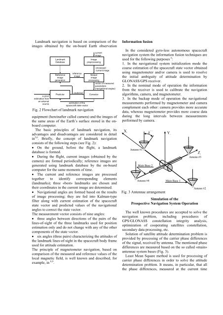
Fig. 3 Antennae arrangement<br />
Main Base 1<br />
Z0<br />
Antenn #3<br />
Simulation <strong>of</strong> <strong>the</strong><br />
Prospective Navigation System Operation<br />
Antenn #2<br />
The well known procedures are accepted to solve <strong>the</strong><br />
<strong>navigation</strong> problem, including procedures <strong>of</strong><br />
GPS/GLONASS constellation integrity analysis,<br />
optimization <strong>of</strong> cooperating <strong>satellite</strong>s constellation,<br />
secondary data processing, etc.<br />
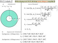
Solution <strong>of</strong> <strong>satellite</strong> attitude determination problem is<br />
provided by processing <strong>of</strong> <strong>the</strong> carrier phase differences<br />
<strong>of</strong> <strong>the</strong> signal, received by antenna. The mentioned phase<br />
differences are measured based on <strong>the</strong> so called «main»<br />
antennae <strong>system</strong> bases (Fig. 3).<br />
Least Mean Square method is used for processing <strong>of</strong><br />
carrier phase differences in order to solve <strong>the</strong> attitude<br />
determination problem. It means, in particular, that all<br />
<strong>the</strong> phase differences, measured at <strong>the</strong> current time