the advanced concept of small satellite integrated navigation system ...
the advanced concept of small satellite integrated navigation system ...
the advanced concept of small satellite integrated navigation system ...

Create successful ePaper yourself
Turn your PDF publications into a flip-book with our unique Google optimized e-Paper software.
INPE / ABCM 14th International Symposium on<br />
Space Flight Dynamics – ISSFD XIV, 8-11<br />
February 1999, Sao Paolo, Brazil<br />
THE ADVANCED CONCEPT OF<br />
SMALL SATELLITE INTEGRATED NAVIGATION SYSTEM,<br />
BASED ON GPS/GLONASS TECHNIQUE *<br />
Mikhail N. Krasilshikov,<br />
V. Dishel, K. Sypalo, D. Kozorez, M. Jacobson<br />
Moscow State Aviation Institute (Technical University) «MAI»<br />
4, Volokolamskoye sh., Moscow, GSP, 125871, RUSSIA<br />
Phone: (7 095) 158-4782. Fax: (7 095) 158-2977. E-mail: jmv57@orc.ru<br />
K. Janschek<br />
Dresden University <strong>of</strong> Technology (TUD)<br />
D-01062 Dresden, GERMANY<br />
Phone: ++49-351-463-4045. Fax: ++49-351-463-7039. E-mail: janschek@eatns1.et.tu-dresden.de<br />
Abstract<br />
The authors discuss a prospective approach to<br />
solution <strong>of</strong> <strong>the</strong> spacecraft <strong>navigation</strong>al problem by an<br />
autonomous gyro-less <strong>navigation</strong> <strong>system</strong>. Its operation<br />
is based on use <strong>of</strong> an on-board GPS/GLONASS<br />
receiver as a primary source <strong>of</strong> <strong>navigation</strong>al<br />
information, and payload earth observation camera and<br />
a magnetometer as auxiliary <strong>navigation</strong>al sensors, and<br />
information fusion techniques and aimed at effective<br />
use <strong>of</strong> information from all <strong>the</strong> sources. The principles<br />
<strong>of</strong> GLONASS/GPS <strong>navigation</strong>, models and algorithms<br />
used for simulation <strong>of</strong> <strong>the</strong> <strong>navigation</strong> process are<br />
considered in detail. Accuracy estimations received as<br />
<strong>the</strong> result <strong>of</strong> Monte-Carlo simulation applied to TUD-<br />
Satellite demonstration mission are cited.<br />
Key words: spacecraft autonomous <strong>navigation</strong>, gyroless<br />
<strong>navigation</strong>, information fusion, GPS, GLONASS,<br />
landmark, magnetometer.<br />
Introduction<br />
During <strong>the</strong> next 10-15 years <strong>the</strong> number <strong>of</strong> LEO<br />
spacecraft will increase up to hundreds, primarily due to<br />
creation <strong>of</strong> LEO communication <strong>system</strong>s such as<br />
IRIDIUM, GLOBALSTAR or TELEDESIC. Support <strong>of</strong><br />
such numerous constellations is a heavy burden on <strong>the</strong><br />
ground control segment from both technical and<br />
financial points <strong>of</strong> view, so it is expedient to transfer<br />
solution <strong>of</strong> many tasks that are traditionally solved on<br />
<strong>the</strong> ground to <strong>the</strong> spacecraft on-board <strong>system</strong>s.<br />
* * funded by European Community under contract INTAS-96-2156<br />
In this paper <strong>the</strong> authors consider a possible approach<br />
to solve on board one <strong>of</strong> such tasks, namely, <strong>the</strong><br />
<strong>navigation</strong>al one, i. e. <strong>the</strong> problem <strong>of</strong> determination <strong>of</strong><br />
<strong>the</strong> spacecraft position, velocity, attitude and angular<br />
rate.<br />
Obviously, on-board receivers <strong>of</strong> global <strong>satellite</strong><br />
positioning <strong>system</strong>s such as American GPS and Russian<br />
GLONASS can solve <strong>the</strong> positioning problem. Besides,<br />
<strong>advanced</strong> receivers, such as <strong>the</strong> Russian device<br />
described in this paper, can use signals <strong>of</strong> both <strong>system</strong>s<br />
and determine not only spacecraft position and velocity,<br />
but also attitude and angular rate.<br />
At <strong>the</strong> same time, long life times <strong>of</strong> <strong>the</strong> modern<br />
communication <strong>satellite</strong>s call for increased reliability <strong>of</strong><br />
<strong>navigation</strong>al <strong>system</strong>s. Instead <strong>of</strong> traditional hardware<br />
redundancy, i. e. usage <strong>of</strong> several dedicated<br />
<strong>navigation</strong>al devices (e. g. receivers), an alternative<br />
approach based on functional redundancy is<br />
suggested 2,6 . In accordance with this approach, a<br />
minimum hardware autonomous <strong>navigation</strong> <strong>system</strong> for<br />
low-earth orbiting spacecraft can be created using<br />
GPS/GLONASS receiver as <strong>the</strong> source <strong>of</strong> <strong>navigation</strong>al<br />
information during <strong>the</strong> nominal operation and on-board<br />
earth observation camera and magnetometer, both<br />
installed on board as <strong>the</strong> secondary payload, for backup<br />
<strong>navigation</strong>. The fusion <strong>of</strong> <strong>the</strong>se information sources is<br />
performed by <strong>advanced</strong> filtering and estimation<br />
methods.<br />
Such an approach provides an adequately accurate<br />
and at <strong>the</strong> same time a cheap and reliable solution to <strong>the</strong><br />
problem <strong>of</strong> spacecraft <strong>navigation</strong>: any single device<br />
(receiver or camera or magnetometer) can provide
solution to <strong>the</strong> <strong>navigation</strong>al problem, while necessary<br />
redundancy is provided by use <strong>of</strong> secondary payload,<br />
originally not assigned for <strong>navigation</strong>al purposes.<br />
The paper presents <strong>the</strong> overall <strong>system</strong> architecture<br />
with emphasis on <strong>the</strong> <strong>advanced</strong> GLONASS/GPS<br />
receiver and first performance results which have been<br />
derived for <strong>the</strong> TUD-Satellite demonstration mission 7 as<br />
<strong>the</strong> application reference by computer simulation <strong>of</strong> <strong>the</strong><br />
<strong>navigation</strong> process.<br />
Basic Navigational Techniques<br />
GPS/GLONASS Navigation<br />
GPS/GLONASS <strong>navigation</strong> is based on utilization <strong>of</strong><br />
multi-channel GPS/GLONASS <strong>integrated</strong> receiver for<br />
solution <strong>of</strong> both orbit and attitude determination<br />
problems.<br />
The main advantages <strong>of</strong> GPS/GLONASS <strong>navigation</strong><br />
are:<br />
• redundancy <strong>of</strong> involved <strong>navigation</strong>al <strong>satellite</strong>s<br />
belonging to both GPS and GLONASS constellations,<br />
• absence <strong>of</strong> Selective Availability mode <strong>of</strong> operation<br />
for GLONASS <strong>navigation</strong>,<br />
• more favorable (compared to GPS) observability <strong>of</strong><br />
GLONASS <strong>satellite</strong>s as applied to such reference<br />
missions as GLONASS, IRIDIUM, etc.<br />
The main disadvantages are:<br />
• necessity to have backup on-board <strong>navigation</strong> and<br />
attitude determination <strong>system</strong> to provide coarse<br />
position, velocity, and attitude estimations to obtain<br />
initial data for GPS/GLONASS attitude determination<br />
procedure,<br />
• necessity to have on-board antenna <strong>system</strong> (3 or 4<br />
antennae) and, <strong>the</strong>refore, 3 or 4 different receivers for<br />
attitude determination problem solution,<br />
• influence <strong>of</strong> <strong>the</strong> <strong>small</strong> length <strong>of</strong> on-board antenna<br />
<strong>system</strong> baseline, <strong>of</strong> <strong>the</strong> <strong>satellite</strong> body distortion and <strong>of</strong><br />
<strong>the</strong> multi-beam effect as unfavorable factors on solution<br />
<strong>of</strong> <strong>the</strong> attitude determination problem.<br />
Fig. 1. Simplified diagram <strong>of</strong> <strong>the</strong> on-board<br />
GLONASS/GPS s<strong>of</strong>tware arrangement<br />
Algorithms for determination <strong>of</strong> position, velocity,<br />
and time are known very well nowadays and<br />
implemented in various space vehicles. That is why,<br />
below we will pay attention only to peculiarities <strong>of</strong><br />
implementation <strong>of</strong> such algorithms.<br />
It is known, that to solve <strong>the</strong> <strong>navigation</strong> problem it is<br />
necessary to perform <strong>the</strong> following actions:<br />
• search <strong>of</strong> <strong>satellite</strong> signals,<br />
• capture <strong>of</strong> signals,<br />
• signals tracking,<br />
and simultaneously to provide receiving and decoding<br />
<strong>of</strong> <strong>the</strong> service information. Besides, we have to<br />
compensate ionosphere refraction (for spacecraft<br />
applications) as well as to provide correction <strong>of</strong> <strong>the</strong><br />
measurement results by correction <strong>of</strong> <strong>the</strong> time scale and<br />
frequency <strong>of</strong> on-board generator <strong>of</strong> each cooperating<br />
<strong>satellite</strong>.<br />
Almanac data, also transmitted in <strong>the</strong> message, are<br />
used for both <strong>the</strong> working constellation selection and<br />
signal search and tracking. The position and velocity<br />
components <strong>of</strong> each <strong>navigation</strong> <strong>satellite</strong> at <strong>the</strong><br />
measurement time instant are computed by short term<br />
propagation, using ephemeris information. To solve <strong>the</strong><br />
<strong>navigation</strong>al problem itself, various data processing<br />
algorithms can be used, such as Kalman filter or Least<br />
Square Method modifications.<br />
All <strong>the</strong> above listed operations, which should be<br />
implemented during every single <strong>navigation</strong>al session,<br />
can be provided by a complex set <strong>of</strong> subroutines<br />
(modules), illustrated in Fig. 1.<br />
We will consider <strong>the</strong> problem <strong>of</strong> <strong>the</strong> <strong>satellite</strong> attitude<br />
determination as <strong>the</strong> problem <strong>of</strong> <strong>the</strong> antenna <strong>system</strong><br />
baselines attitude determination with respect to <strong>the</strong> axes<br />
<strong>of</strong> <strong>the</strong> reference frame.<br />
It is known that second differences <strong>of</strong> <strong>the</strong><br />
pseudoranges <strong>of</strong> two <strong>navigation</strong>al are functions <strong>of</strong><br />
second differences <strong>of</strong> <strong>the</strong> carrier phases <strong>of</strong> signals from<br />
<strong>the</strong> mentioned <strong>satellite</strong>s.<br />
The specific feature <strong>of</strong> <strong>the</strong> phase differences<br />
measurement is restriction <strong>of</strong> <strong>the</strong> phase difference in <strong>the</strong><br />
range [0, 2π]. To perform <strong>the</strong> measurement process it is<br />
necessary to develop so called counter (indicator) <strong>of</strong> <strong>the</strong><br />
integers <strong>of</strong> <strong>the</strong> signal periods. This counter should<br />
indicate output +1 or -1, if <strong>the</strong> magnitude <strong>of</strong> <strong>the</strong> phase<br />
difference reaches <strong>the</strong> value 0 or 2π, correspondingly.<br />
This counter is in fact <strong>the</strong> essence <strong>of</strong> <strong>the</strong> attitude<br />
determination algorithm.<br />
Backup (Landmark and Magnetometer) Navigation
Landmark <strong>navigation</strong> is based on comparison <strong>of</strong> <strong>the</strong><br />
images obtained by <strong>the</strong> on-board Earth observation<br />
a priori<br />
estimation from<br />
an external<br />
source<br />
Landmark<br />
Database<br />
Reference<br />
image<br />
generation<br />
Predictor<br />
reference<br />
image<br />
prediction<br />
estimation <strong>of</strong> <strong>the</strong><br />
spacecraft state vector<br />
Fig. 2 Flowchart <strong>of</strong> landmark <strong>navigation</strong><br />
current<br />
image<br />
Image<br />
preprocessing<br />
Mutual<br />
image<br />
processing<br />
vector <strong>of</strong> measured<br />
parameters<br />
(<strong>navigation</strong>al angles)<br />
Corrector<br />
processed<br />
current image<br />
equipment (hereinafter called camera) and <strong>the</strong> images <strong>of</strong><br />
<strong>the</strong> same areas <strong>of</strong> <strong>the</strong> Earth’s surface stored in <strong>the</strong> onboard<br />
computer.<br />
The basic principles <strong>of</strong> landmark <strong>navigation</strong>, its<br />
advantages and disadvantages are considered in detail<br />
in 5,6 . Briefly, <strong>the</strong> <strong>concept</strong> <strong>of</strong> landmark <strong>navigation</strong><br />
consists <strong>of</strong> <strong>the</strong> following steps (see Fig. 2):<br />
• On <strong>the</strong> ground, before <strong>the</strong> flight, a landmark<br />
database is formed.<br />
• During <strong>the</strong> flight, current images (obtained by <strong>the</strong><br />
camera) are formed periodically; reference images are<br />
generated using landmark database by <strong>the</strong> on-board<br />
computer for <strong>the</strong> same moments <strong>of</strong> time.<br />
• The current and reference images are processed<br />
toge<strong>the</strong>r to identify corresponding elements<br />
(landmarks); three «best» landmarks are chosen and<br />
<strong>the</strong>ir coordinates in <strong>the</strong> current image are determined.<br />
• Navigational angles are formed based on <strong>the</strong> results<br />
<strong>of</strong> image processing; <strong>the</strong>y are fed into Kalman-type<br />
filter along with current estimation <strong>of</strong> <strong>the</strong> spacecraft<br />
state vector and predicted values <strong>of</strong> <strong>the</strong> <strong>navigation</strong>al<br />
angles to correct <strong>the</strong> state vector.<br />
The measurement vector consists <strong>of</strong> nine angles:<br />
• three angles between directions <strong>of</strong> <strong>the</strong> pairs <strong>of</strong> <strong>the</strong><br />
lines-<strong>of</strong>-sight <strong>of</strong> <strong>the</strong> three landmarks used for position<br />
estimation only and do not change with any <strong>of</strong> <strong>the</strong> o<strong>the</strong>r<br />
components <strong>of</strong> <strong>the</strong> state vector.<br />
• six angles (three pairs) characterizing <strong>the</strong> attitudes <strong>of</strong><br />
<strong>the</strong> landmark lines-<strong>of</strong>-sight in <strong>the</strong> spacecraft body frame<br />
used for attitude estimation.<br />
The principle <strong>of</strong> magnetometer <strong>navigation</strong>, based on<br />
comparison <strong>of</strong> <strong>the</strong> measured and reference values <strong>of</strong> <strong>the</strong><br />
local magnetic field, is well known and described, for<br />
example, in 8,9 .<br />
Information fusion<br />
In <strong>the</strong> considered gyro-less autonomous spacecraft<br />
<strong>navigation</strong> <strong>system</strong> <strong>the</strong> information fusion techniques are<br />
used for <strong>the</strong> following purposes 6 :<br />
1. In <strong>the</strong> <strong>navigation</strong>al <strong>system</strong> initialization mode <strong>the</strong><br />
coarse estimation <strong>of</strong> <strong>the</strong> spacecraft state vector obtained<br />
using magnetometer and/or camera is used to resolve<br />
<strong>the</strong> initial ambiguity <strong>of</strong> attitude determination by<br />
GLONASS/GPS receiver.<br />
2. In <strong>the</strong> nominal mode <strong>of</strong> operation <strong>the</strong> information<br />
from <strong>the</strong> receiver is used to calibrate <strong>the</strong> <strong>navigation</strong><br />
algorithms, camera, and magnetometer.<br />
3. In <strong>the</strong> backup mode <strong>of</strong> operation <strong>the</strong> <strong>navigation</strong>al<br />
measurements performed by magnetometer and camera<br />
complement each o<strong>the</strong>r: camera provides more accurate<br />
data, whereas magnetometer provides more coarse data<br />
during <strong>the</strong> long intervals between measurements<br />
performed by camera.<br />
m a x<br />
X0 δ Y0<br />
Antenn #1<br />
Main Base 2<br />
Antenn #4<br />
Fig. 3 Antennae arrangement<br />
Main Base 1<br />
Z0<br />
Antenn #3<br />
Simulation <strong>of</strong> <strong>the</strong><br />
Prospective Navigation System Operation<br />
Antenn #2<br />
The well known procedures are accepted to solve <strong>the</strong><br />
<strong>navigation</strong> problem, including procedures <strong>of</strong><br />
GPS/GLONASS constellation integrity analysis,<br />
optimization <strong>of</strong> cooperating <strong>satellite</strong>s constellation,<br />
secondary data processing, etc.<br />
Solution <strong>of</strong> <strong>satellite</strong> attitude determination problem is<br />
provided by processing <strong>of</strong> <strong>the</strong> carrier phase differences<br />
<strong>of</strong> <strong>the</strong> signal, received by antenna. The mentioned phase<br />
differences are measured based on <strong>the</strong> so called «main»<br />
antennae <strong>system</strong> bases (Fig. 3).<br />
Least Mean Square method is used for processing <strong>of</strong><br />
carrier phase differences in order to solve <strong>the</strong> attitude<br />
determination problem. It means, in particular, that all<br />
<strong>the</strong> phase differences, measured at <strong>the</strong> current time
GPS & GLONASS constellation and user motion model<br />
User<br />
attitude<br />
simulator<br />
E tr<br />
S<br />
User<br />
ephemerise<br />
generator<br />
X tr<br />
Calculator <strong>of</strong> <strong>the</strong><br />
"true" antennae <strong>system</strong> position<br />
in <strong>the</strong> inertial frame<br />
errors <strong>of</strong><br />
<strong>system</strong><br />
initialization<br />
ephemerise<br />
errors<br />
User "On-Board" S<strong>of</strong>tware<br />
E ref<br />
s<br />
re f<br />
X s<br />
X ref<br />
ant<br />
S<br />
E* s<br />
X* s<br />
X tr<br />
ΔX N S<br />
ant<br />
GPS & GLONASS<br />
ephemerise<br />
generator<br />
X tr<br />
N S<br />
Definition <strong>of</strong> <strong>the</strong> observed<br />
GPS & GLONASS <strong>satellite</strong>s<br />
X tr<br />
O N S<br />
Simulator <strong>of</strong> <strong>the</strong><br />
GPS & GLONASS<br />
<strong>navigation</strong>al message<br />
ref<br />
X (-30)<br />
O N S<br />
Integration <strong>of</strong> <strong>the</strong> observed<br />
GPS & GLONASS <strong>satellite</strong>s<br />
reference trajectories<br />
ref<br />
X (t)<br />
O N S<br />
Formation <strong>of</strong> <strong>the</strong><br />
reference<br />
measurement results<br />
φ ref<br />
Calculator <strong>of</strong> <strong>the</strong><br />
reference antennae <strong>system</strong><br />
position in <strong>the</strong> inertial frame User attitude<br />
data processing<br />
algorithm<br />
OUTPUT<br />
DATA<br />
X tr<br />
O N S<br />
X tr<br />
set <strong>of</strong><br />
measurement errors<br />
Formation <strong>of</strong> <strong>the</strong> "true"<br />
measurement results<br />
ant<br />
φ tr<br />
ref ref<br />
ρ , δρ<br />
User position & velocity<br />
data processing<br />
algorithm<br />
tr tr<br />
ρ , δρ<br />
Fig. 4 Simplified diagram <strong>of</strong> simulation<br />
instant using all <strong>the</strong> observed <strong>navigation</strong>al <strong>satellite</strong>s, are<br />
considered as a complete sample to be processed by <strong>the</strong><br />
LMS method. As <strong>the</strong> result, it is not necessary to<br />
involve complete ma<strong>the</strong>matical model <strong>of</strong> angular<br />
<strong>satellite</strong> motion in <strong>the</strong> attitude determination algorithm.<br />
The simplified diagram <strong>of</strong> simulation is given in Fig.<br />
4. The following notations are used in this figure:<br />
X is <strong>the</strong> vector <strong>of</strong> «true» TUD <strong>satellite</strong> position and<br />
tr<br />
S<br />
velocity components in <strong>the</strong> absolute inertial frame<br />
(IF2000),<br />
E is <strong>the</strong> vector <strong>of</strong> «true» TUD <strong>satellite</strong> Euler angles,<br />
tr<br />
S<br />
tr<br />
X NS is <strong>the</strong> vector <strong>of</strong> «true» GLONASS and GPS<br />
<strong>satellite</strong>s ephemerides,<br />
tr<br />
X ant is <strong>the</strong> vector <strong>of</strong> «true» antenna position in <strong>the</strong><br />
IF2000 frame (see below in detail),<br />
tr<br />
X ONS is <strong>the</strong> vector <strong>of</strong> «true» observed <strong>navigation</strong>al<br />
<strong>satellite</strong>s (ONS) ephemerides,<br />
tr<br />
ρ is <strong>the</strong> vector <strong>of</strong> «true» pseudorange measurement<br />
results, obtained from <strong>the</strong> observed <strong>navigation</strong>al<br />
<strong>satellite</strong>s,<br />
tr<br />
δρ is <strong>the</strong> vector <strong>of</strong> «true» pseudorange rate<br />
measurement results, obtained from <strong>the</strong> observed<br />
<strong>navigation</strong>al <strong>satellite</strong>s,<br />
tr<br />
Φ is <strong>the</strong> vector <strong>of</strong> «true» carrier phase difference<br />
measurement results, calculated for <strong>the</strong> observed<br />
<strong>navigation</strong>al <strong>satellite</strong>s,<br />
ref<br />
X ONS is <strong>the</strong> vector <strong>of</strong> observed <strong>navigation</strong>al <strong>satellite</strong>s<br />
ephemerides, which corresponds to <strong>the</strong> <strong>navigation</strong>al<br />
message,<br />
ref<br />
X NS is <strong>the</strong> vector <strong>of</strong> observed <strong>navigation</strong>al <strong>satellite</strong>s<br />
short term («reference») ephemerides, calculated by <strong>the</strong><br />
<strong>satellite</strong> onboard computer,<br />
ref<br />
X S is <strong>the</strong> user «reference» state vector, calculated by<br />
<strong>the</strong> onboard computer bases on <strong>the</strong> previous<br />
estimations,<br />
ref<br />
E S is <strong>the</strong> vector <strong>of</strong> <strong>the</strong> «reference» <strong>satellite</strong> Euler<br />
angles, calculated by onboard computer based on <strong>the</strong><br />
previous estimations and angular motion model,<br />
ref<br />
X ant is <strong>the</strong> vector <strong>of</strong> <strong>the</strong> «reference» antenna position<br />
in <strong>the</strong> IF2000, calculated by onboard computer, using<br />
ref ref<br />
XS<br />
and ES<br />
data,<br />
ref ref ref<br />
ρ , δρ , ϕ are corresponding reference<br />
measurement data, generated based on <strong>the</strong><br />
corresponding reference vectors<br />
ref ref ref ref<br />
XS<br />
, Xant<br />
, ES<br />
, XONS<br />
.<br />
* *<br />
E S , XS<br />
are <strong>the</strong> vectors <strong>of</strong> estimations <strong>of</strong> <strong>the</strong> user<br />
attitude, position and velocity.<br />
tr tr tr<br />
To obtain <strong>the</strong> values <strong>of</strong> XS<br />
, ES<br />
, X NS , <strong>the</strong> most<br />
accurate and complete models <strong>of</strong> motion as well as<br />
high-accuracy integration method are used.<br />
Ma<strong>the</strong>matical Models and Algorithms<br />
Let us emphasize, that for simulation <strong>of</strong> <strong>the</strong><br />
considered <strong>navigation</strong> <strong>system</strong> one has to create <strong>the</strong><br />
following ma<strong>the</strong>matical models and algorithms:<br />
• GLONASS and GPS constellation model;<br />
• GLONASS and GPS <strong>satellite</strong> observability model;<br />
• user orbital and angular motion models;<br />
• <strong>navigation</strong>al message and receiver antennae <strong>system</strong><br />
models;<br />
• algorithm <strong>of</strong> user position and velocity<br />
determination;<br />
• algorithm <strong>of</strong> user attitude determination.<br />
All <strong>the</strong> mentioned models have been created,<br />
considering wide set <strong>of</strong> uncontrollable factors and<br />
errors, such as GLONASS and GPS ephemerides<br />
maintenance <strong>system</strong>atic errors caused by <strong>the</strong> errors <strong>of</strong><br />
orbit determination <strong>of</strong> <strong>the</strong> <strong>navigation</strong> <strong>satellite</strong>s by <strong>the</strong>
on-ground complex; pseudorange and pseudorange rate<br />
<strong>system</strong>atic and random measurement errors caused by<br />
ionosphere delay, receiver clock drift and internal<br />
receiver noise; carrier phase difference measurement<br />
<strong>system</strong>atic and random errors caused by multi-path<br />
phenomenon, receiver clock drift, internal receiver<br />
noise; <strong>system</strong>atic and random errors <strong>of</strong> <strong>system</strong><br />
initialization caused by <strong>the</strong> errors <strong>of</strong> auxiliary sensors<br />
data.<br />
A recursive Bayes algorithm (a modification <strong>of</strong><br />
Kalman filtering) or <strong>the</strong> Least Mean Square algorithm<br />
has been used for user position and velocity<br />
determination. The latter has been used also for <strong>the</strong> user<br />
attitude determination.<br />
As it was said above, two levels <strong>of</strong> <strong>the</strong> used models<br />
have been developed for simulation: <strong>the</strong> more accurate<br />
model and integration method for «true» ephemerides<br />
generation and simplified model and integration<br />
algorithm for simulation <strong>of</strong> both <strong>navigation</strong> messages<br />
and «onboard» short-term ephemerides generation.<br />
Ma<strong>the</strong>matical model <strong>of</strong> <strong>the</strong> <strong>navigation</strong>al <strong>satellite</strong>s<br />
motion<br />
Firstly, let us pay attention to <strong>the</strong> «true» ephemerides<br />
generation technique. Below we turn our attention only<br />
to its main specific features.<br />
The ma<strong>the</strong>matical model <strong>of</strong> «true» ephemerides<br />
generation considers influence <strong>of</strong> <strong>the</strong> following<br />
uncontrollable factors (disturbances): force resulting<br />
from <strong>the</strong> Earth oblateness according to Cunningham<br />
expansion 3 till <strong>the</strong> 8th order, force resulting from Sun<br />
and Moon gravitational influence, aerodynamic drag<br />
force, force resulting form <strong>the</strong> solar pressure.<br />
The highly accurate Dormand-Prince integration<br />
method 3 <strong>of</strong> <strong>the</strong> 5(4) order with automatically adjustable<br />
step has been used for computation GPS and<br />
GLONASS <strong>satellite</strong>s «true» position and velocity,<br />
considering <strong>the</strong> above mentioned disturbances. To<br />
provide efficiency <strong>of</strong> obtained integration results<br />
utilization, one uses Chebyshev’s polynomial<br />
approximation technique 3 . The order <strong>of</strong> polynomial was<br />
accepted equal to 16 and approximation interval has<br />
been accepted equal to 1000 sec.<br />
The simplified model for simulation <strong>of</strong> both<br />
<strong>navigation</strong> messages and «onboard» short-term<br />
ephemerides generation (so called «reference» data)<br />
considers <strong>the</strong> force resulting from <strong>the</strong> Earth oblateness<br />
according to Cunningham expansion till <strong>the</strong> 2nd order<br />
and force resulting from Sun and Moon gravitational<br />
influence.<br />
The standard Runge-Kutta integration method <strong>of</strong> <strong>the</strong><br />
2/6 rule with fixed step was used for computation <strong>of</strong><br />
GPS and GLONASS <strong>satellite</strong>s «reference» position and<br />
velocity, considering <strong>the</strong> above mentioned disturbances.<br />
To utilize <strong>the</strong> obtained integration results for<br />
«reference» ephemerides generation Chebyshev’s<br />
polynomial approximation technique has been used as<br />
well.<br />
To simulate <strong>the</strong> error <strong>of</strong> ephemerides maintenance<br />
one uses «true» ephemerides, corresponding to <strong>the</strong><br />
closest half an hour, «distorted» by <strong>the</strong> additive random<br />
vector with zero ma<strong>the</strong>matical expectation and diagonal<br />
covariance matrix with <strong>the</strong> following r.m.s. values:<br />
σ r = σl<br />
= σn<br />
= 10m.<br />
; σ 0 05m<br />
s,<br />
r � = σ�<br />
= σ l n�<br />
= . /<br />
where <strong>the</strong> r, l, n subscripts denote radial, tangential and<br />
normal directions correspondingly.<br />
Ma<strong>the</strong>matical model <strong>of</strong> <strong>the</strong> user <strong>satellite</strong> motion<br />
Two levels <strong>of</strong> <strong>the</strong> models complexity have been used<br />
for simulation <strong>of</strong> <strong>the</strong> user motion: <strong>the</strong> more accurate<br />
models and integration method for «true» <strong>satellite</strong><br />
position and velocity computation and simplified model<br />
and integration algorithm for <strong>the</strong> «reference» data<br />
generation by <strong>the</strong> «onboard» s<strong>of</strong>tware. The highly<br />
accurate technique for <strong>the</strong> user position and velocity<br />
computation is <strong>the</strong> same as for <strong>the</strong> «true » GPS and<br />
GLONASS <strong>satellite</strong>s ephemerides generation.<br />
To use <strong>the</strong> obtained integration results for <strong>the</strong> user<br />
«true» ephemerides generation one uses Chebyshev’s<br />
polynomial approximation technique. The order <strong>of</strong><br />
polynomial is equal to 16 and approximation interval is<br />
equal to 500 sec.<br />
The simplified «onboard» user motion model for <strong>the</strong><br />
«reference» data performing considers <strong>the</strong> force<br />
resulting from <strong>the</strong> Earth oblateness according to<br />
Cunningham expansion till <strong>the</strong> 2nd order and <strong>the</strong><br />
aerodynamic drag force.<br />
The standard Runge-Kutta integration method <strong>of</strong> <strong>the</strong><br />
2/6 rule with fixed step is used for computation <strong>of</strong> <strong>the</strong><br />
user «reference» position and velocity, considering <strong>the</strong><br />
above mentioned disturbances. A priori data are used as<br />
initial conditions for <strong>the</strong> «onboard» equations <strong>of</strong> <strong>the</strong><br />
user motion. Later <strong>the</strong> current estimations <strong>of</strong> position<br />
and velocity are used, when «User position and<br />
velocity data processing algorithm» unit is initialized.<br />
The simplest model <strong>of</strong> <strong>the</strong> user angular motion was<br />
accepted as <strong>the</strong> «onboard» one due to LMS algorithm<br />
utilization in <strong>the</strong> «User attitude data processing<br />
algorithm» unit, namely:<br />
ref<br />
ref<br />
Es = 0,<br />
Es<br />
= ( ϑ ψ γ)<br />
� ,<br />
where υ, ψ, γ are pitch, yaw and roll correspondingly.
Ma<strong>the</strong>matical models <strong>of</strong> <strong>navigation</strong>al measurements<br />
According to <strong>the</strong> accepted simulation technique <strong>the</strong>re<br />
are <strong>the</strong> following two sorts <strong>of</strong> <strong>navigation</strong>al measurement<br />
models: <strong>the</strong> models <strong>of</strong> <strong>the</strong> «true» measurements and <strong>the</strong><br />
models <strong>of</strong> <strong>the</strong> «reference» measurements, used in <strong>the</strong><br />
«onboard» s<strong>of</strong>tware.<br />
Ma<strong>the</strong>matical models <strong>of</strong> <strong>the</strong> «true» measurements<br />
consider <strong>the</strong> following errors:<br />
• <strong>system</strong>atic errors, considered as random variables<br />
formed by corresponding first-order shaping filters:<br />
• error caused by onboard user receiver clock drift,<br />
• error, caused by ionospheric delay,<br />
• error <strong>of</strong> <strong>the</strong> pseudorange rate measurement,<br />
• error, caused by multi-path phenomenon,<br />
• random errors, considered as sequences <strong>of</strong><br />
independent Gaussian random variables with zero<br />
ma<strong>the</strong>matical expectation and fixed variances:<br />
• error caused by internal receiver noise,<br />
• error <strong>of</strong> <strong>the</strong> pseudorange rate measurement,<br />
• error, caused by internal receiver noise.<br />
Algorithms <strong>of</strong> <strong>the</strong> user position and velocity<br />
determination<br />
Two versions <strong>of</strong> <strong>the</strong> data processing algorithms can<br />
be utilized for <strong>the</strong> user position and velocity<br />
determination, namely a recursive Bayes algorithm,<br />
which is a modification <strong>of</strong> <strong>the</strong> Kalman filter, and <strong>the</strong><br />
Least Mean Square algorithm <strong>of</strong> <strong>the</strong> complete sample<br />
processing.<br />
The modification <strong>of</strong> <strong>the</strong> Kalman filtering algorithm<br />
has <strong>the</strong> following specific features. There are two cycles<br />
<strong>of</strong> algorithm operation: external and internal ones. The<br />
external cycle means enumeration <strong>of</strong> <strong>the</strong> <strong>navigation</strong><br />
sessions, and internal cycle means enumeration <strong>of</strong> <strong>the</strong><br />
observed <strong>navigation</strong>al <strong>satellite</strong>s during given <strong>navigation</strong><br />
session. Thus, <strong>navigation</strong> session is <strong>the</strong> time instant <strong>of</strong><br />
<strong>the</strong> receiving <strong>of</strong> <strong>the</strong> <strong>navigation</strong>al messages from all <strong>the</strong><br />
observed GPS and GLONASS <strong>satellite</strong>s (taking into<br />
account <strong>the</strong> restriction on <strong>the</strong> elevation).<br />
Algorithm <strong>of</strong> <strong>the</strong> TUD <strong>satellite</strong> attitude determination<br />
This Least Mean Square algorithm also has two<br />
cycles (<strong>the</strong> internal and external ones), implemented in<br />
<strong>the</strong> same way, as for determination <strong>of</strong> <strong>the</strong> user position<br />
and velocity. The difference consists in <strong>the</strong> way <strong>of</strong> <strong>the</strong><br />
observation matrix computation. In contrast to position<br />
and velocity determination LMS algorithm, here one<br />
computes <strong>the</strong> elements <strong>of</strong> <strong>the</strong> comprehensive<br />
observation matrix in respect to pitch, yaw and roll.<br />
Besides, for prediction <strong>of</strong> <strong>the</strong> Euler’s angles estimations<br />
and covariance matrix for <strong>the</strong> next <strong>navigation</strong> session,<br />
<strong>the</strong> simplified model <strong>of</strong> <strong>the</strong> TUD <strong>satellite</strong> is used.<br />
Simulation Results<br />
Input Data for Simulation<br />
The reference mission used during computer<br />
simulation <strong>of</strong> <strong>the</strong> <strong>navigation</strong>al <strong>system</strong> is based on orbital<br />
characteristics <strong>of</strong> <strong>the</strong> TUD- Satellite 6 . This <strong>small</strong> (about<br />
100 kg) <strong>satellite</strong> will be placed on a 500 km, 53 o<br />
circular orbit and will have no orbit control means. The<br />
attitude control <strong>system</strong> will be based on passive gravity<br />
gradient stabilization combined with active attitude<br />
stabilization and control using momentum wheel and<br />
magnetotorquers.<br />
The simulation interval is equal to 6000 sec; this<br />
magnitude is approximately equal to <strong>the</strong> TUD <strong>satellite</strong><br />
period <strong>of</strong> revolution. Ma<strong>the</strong>matical model <strong>of</strong> <strong>the</strong> TUD<br />
<strong>satellite</strong> angular motion corresponds to 7 .<br />
The above mentioned five versions <strong>of</strong> GLONASS and<br />
GPS constellations are considered.<br />
Errors <strong>of</strong> <strong>the</strong> TUD <strong>satellite</strong> position and velocity<br />
determination are:<br />
• for GLONASS <strong>the</strong> r.m.s. error <strong>of</strong> <strong>the</strong> TUD <strong>satellite</strong><br />
position is equal to 25 m; <strong>the</strong> r.m.s. error <strong>of</strong> its<br />
velocity is equal to 0,5 cm/sec,<br />
• for GPS <strong>the</strong> r.m.s. error <strong>of</strong> <strong>the</strong> TUD <strong>satellite</strong> position<br />
is equal to 100 m; <strong>the</strong> r.m.s. error <strong>of</strong> its velocity is<br />
equal to 50 cm/sec (taking into account GPS C/A<br />
mode <strong>of</strong> operation).<br />
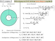
Errors <strong>of</strong> carrier phase differences measurement:<br />
• <strong>the</strong> r.m.s. error <strong>of</strong> <strong>the</strong> <strong>system</strong>atic error, caused by <strong>the</strong><br />
multipath phenomenon is varied in <strong>the</strong> following<br />
way: 0.0033m, 0.005m, 0.01m, 0.033m, 0.05m;<br />
• <strong>the</strong> r.m.s. error <strong>of</strong> <strong>the</strong> additive random noise is equal<br />
to 0.005m.<br />
Description <strong>of</strong> Simulation Results<br />
During <strong>the</strong> simulation <strong>of</strong> <strong>the</strong> user attitude<br />
determination process using GLONASS/GPS receiver,<br />
<strong>the</strong> influence <strong>of</strong> <strong>the</strong> following factors has been<br />
explored:<br />
• various completeness <strong>of</strong> GLONASS and GPS<br />
<strong>navigation</strong> <strong>satellite</strong>s constellation, namely: GLONASS<br />
only, GPS only, GLONASS+GPS, incomplete<br />
GLONASS only, incomplete GLONASS+GPS;<br />
• different length <strong>of</strong> <strong>satellite</strong> antennae <strong>system</strong> base;<br />
• different level <strong>of</strong> <strong>system</strong>atic errors.
All <strong>the</strong> obtained simulation results have been<br />
processed using Monte-Carlo technique.<br />
Below one can see dependencies, which characterize<br />
influence <strong>of</strong> antenna <strong>system</strong> base length, observation<br />
conditions, GLONASS and GPS constellation<br />
RMS values <strong>of</strong> Euler angles, deg.<br />
1.00<br />
0.90<br />
0.80<br />
0.70<br />
0.60<br />
0.50<br />
0.40<br />
0.30<br />
0.20<br />
0.10<br />
0.00<br />
1 2 3 4<br />
Antenna base length, m.<br />
Fig. 5 Incomplete GLONASS+GPS<br />
RMS values <strong>of</strong> Euler angles, deg.<br />
0.90<br />
0.80<br />
0.70<br />
0.60<br />
0.50<br />
0.40<br />
0.30<br />
0.20<br />
0.10<br />
0.00<br />
Incomplete GLONASS + GPS;<br />
r.m.s value<br />
<strong>of</strong> sys. error is 0.005 m.<br />
completeness and <strong>system</strong>atic errors level on <strong>the</strong><br />
accuracy <strong>of</strong> <strong>the</strong> TUD <strong>satellite</strong> attitude determination.<br />
Main attention was paid to <strong>the</strong> influence <strong>of</strong> <strong>the</strong><br />
antenna <strong>system</strong> base length. These results are<br />
demonstrated in Fig. 4 – 8. Each symbol on <strong>the</strong>se<br />
figures corresponds to 30 samples <strong>of</strong> Monte-Carlo<br />
simulation. The magnitude <strong>of</strong> r.m.s. attitude for any<br />
fixed base length depends also on <strong>the</strong> observation<br />
condition and magnitude <strong>of</strong> <strong>system</strong>atic error, which is<br />
fixed and is equal to 0.005m.<br />
Pitch<br />
1 2 3 4 5<br />
Antenna base length, m.<br />
Fig. 6 Complete GLONASS+GPS<br />
Yaw<br />
Roll<br />
Complete GLONASS + GPS;<br />
r.m.s value<br />
<strong>of</strong> sys. error is 0.005 m.<br />
Pitch<br />
Yaw<br />
Roll<br />
5<br />
RMS values <strong>of</strong> Euler angles, deg.<br />
2.00<br />
1.90<br />
1.80<br />
1.70<br />
1.60<br />
1.50<br />
1.40<br />
1.30<br />
1.20<br />
1.10<br />
1.00<br />
0.90<br />
0.80<br />
0.70<br />
0.60<br />
0.50<br />
0.40<br />
0.30<br />
0.20<br />
0.10<br />
0.00<br />
Complete GLONASS;<br />
r.m.s value<br />
<strong>of</strong> sys. error is 0.005 m.<br />
Pitch<br />
1 2 3 4 5<br />
Antenna base length, m.<br />
Fig. 7 Complete GLONASS<br />
RMS values <strong>of</strong> Euler angles, deg.<br />
5.00<br />
4.50<br />
4.00<br />
3.50<br />
3.00<br />
2.50<br />
2.00<br />
1.50<br />
1.00<br />
0.50<br />
0.00<br />
1 2 3 4<br />
Antenna base length, m.<br />
Fig. 8 Incomplete GLONASS<br />
RMS values <strong>of</strong> Euler angles, deg.<br />
1.00<br />
0.90<br />
0.80<br />
0.70<br />
0.60<br />
0.50<br />
0.40<br />
0.30<br />
0.20<br />
0.10<br />
0.00<br />
Fig. 9 GPS only<br />
Yaw<br />
Roll<br />
Incomplete GLONASS;<br />
r.m.s value<br />
<strong>of</strong> sys. error is 0.005 m.<br />
Pitch<br />
1 2 3 4 5<br />
Antenna base length, m.<br />
Yaw<br />
Roll<br />
GPS;<br />
r.m.s value<br />
<strong>of</strong> sys. error is 0.005 m.<br />
Pitch<br />
Yaw<br />
Roll<br />
5
Accuracy <strong>of</strong> Navigation and Attitude Determination<br />
Provided by Auxiliary Sensors<br />
The study has also demonstrated <strong>the</strong> efficiency <strong>of</strong> <strong>the</strong><br />
suggested landmark <strong>navigation</strong> technique: <strong>the</strong><br />
estimation process converges in a very wide scope <strong>of</strong><br />
orbits, camera characteristics, and o<strong>the</strong>r parameters <strong>of</strong><br />
<strong>the</strong> models. For <strong>the</strong> TUD-<strong>satellite</strong> reference mission <strong>the</strong><br />
method provides solution to <strong>the</strong> <strong>navigation</strong>al problem<br />
with maximum error not worse than 4 — 6<br />
kilometers 1,4 . The attitude is determined with <strong>the</strong><br />
maximum error not exceeding 1 degree (yaw) and 20<br />
arc sec (pitch, roll). So, <strong>the</strong> accuracy <strong>of</strong> orbit<br />
determination is much worse that accuracy <strong>of</strong><br />
GLONASS/GPS <strong>navigation</strong>, but <strong>the</strong> accuracy <strong>of</strong> attitude<br />
determination is comparable or even better; <strong>the</strong> latter<br />
fact can be effectively by information fusion.<br />
It is a well known fact that magnetometer <strong>navigation</strong><br />
provides accuracy <strong>of</strong> <strong>navigation</strong> with errors not<br />
exceeding 30-50 km and several degrees,<br />
correspondingly (see 9 and references in it); in o<strong>the</strong>r<br />
words, <strong>the</strong> accuracy is much worse that accuracy <strong>of</strong><br />
GLONASS/GPS or landmark <strong>navigation</strong>. At <strong>the</strong> same<br />
time, magnetometer can provide estimation <strong>of</strong> <strong>the</strong><br />
spacecraft space vector even when <strong>the</strong> initial estimation<br />
is very bad and at any moment <strong>of</strong> time. Hence, its data<br />
can be used for initialization <strong>of</strong> <strong>the</strong> <strong>navigation</strong>al <strong>system</strong><br />
and as a backup source <strong>of</strong> <strong>navigation</strong>al information.<br />
Conclusions<br />
This article shows that autonomous spacecraft<br />
<strong>navigation</strong> <strong>system</strong>, fitting minimal hardware <strong>concept</strong>,<br />
based on use <strong>of</strong> on-board GPS/GLONASS receiver,<br />
earth observation camera and magnetometer, is very<br />
prospective for LEO <strong>satellite</strong>s.<br />
The authors are going to continue <strong>the</strong> research in <strong>the</strong><br />
following main directions:<br />
• fur<strong>the</strong>r development <strong>of</strong> algorithms for attitude<br />
determination using <strong>the</strong> receiver and camera,<br />
• design <strong>of</strong> information fusion algorithms,<br />
• detailed performance evaluation considering<br />
enhances models <strong>of</strong> heterogeneous uncontrollable<br />
factors to obtain more justified numerical results.<br />
Acknowledgments<br />
The research is supported by INTAS Foundation<br />
(contract INTAS-96-2156, project «Autonomous<br />
<strong>navigation</strong> for low-earth orbit spacecraft using<br />
information fusion techniques»).<br />
The authors are grateful to Assis. Pr<strong>of</strong>. K. Sypalo<br />
(MAI) and graduate students I. Belousov, D. Kozorez<br />
(MAI) and T. Boge (TUD) for <strong>the</strong>ir invaluable help in<br />
<strong>the</strong> described research.<br />
References<br />
1. Jacobson, M. V. (1997). Autonomous Spacecraft<br />
Navigation Using Ground Landmarks. Proc. 6th<br />
Alumni Conference <strong>of</strong> <strong>the</strong> ISU, July 1997, Rice Univ.,<br />
Houston, TX, USA<br />
2. Janschek, K., et al. (1998). Minimum Hardware<br />
Concept for LEO Satellites Using Information Fusion.<br />
Proc. 12 th AIAA/USU Conf. On Small Satellites,<br />
Logan, UT.<br />
3. Krasilshikov, M. N., Dishel V. D. (1995).<br />
Methodology and Algorithms <strong>of</strong> Inertial System and<br />
External Data Composing Providing Preset Accuracy<br />
<strong>of</strong> Aerospace Vehicle Navigation. Proc. 1 st Brazilian<br />
Symp. in Inertial Eng. Nov 7 — 13, 1995, Sao-Jose dos<br />
Campos, S. P. Brazil Symp., pp. 1 — 12.<br />
4. Krasilshikov, M. N., Jacobson, M. V. (1995).<br />
Autonomous Spacecraft Navigation Using Ground<br />
Landmarks. Proc. 4th MAI/BUAA Intl. Symp. on<br />
Automatic Control. Moscow, Russia, August 28-30,<br />
1997. pp. 34-38.<br />
5. Krasilshikov, M. N., Jacobson, M. V., Kim, N. V.<br />
(1995). Development <strong>of</strong> Algorithms and S<strong>of</strong>tware for<br />
Autonomous Spacecraft Positioning System Based on<br />
Earth Observation. Proc. 46th IAF Congress. Oslo,<br />
Norway, October 2-6, 1995. Paper IAF-95-A.6.05<br />
6. Janschek, K., Boge, T., Krasilshikov, M., Dishel, V.,<br />
Jacobson, M., Minimum Hardware Concept for LEO<br />
Satellites Using Information Fusion. Proc. 12 th<br />
AIAA/USU Conf. On Small Satellites, Logan, UT,<br />
Sept. 1998. Paper SSC 98-IX-7.<br />
7. TUD-Satellite Phase A, Final Report, TU Dresden,<br />
Germany, April 1998.<br />
8. Spacecraft Attitude Determination and Control. Ed.<br />
by Wertz, J. R. Kluwer Academic Publishers, 1993.<br />
9. Wiegand, M. Autonomous Satellite Navigation via<br />
Kalman Filtering <strong>of</strong> Magnetometer Data. Acta<br />
Astronautica Vol. 38, No. 4-8, pp. 395 — 403, 1996.