Imaging Spectrometer - Horiba
Imaging Spectrometer - Horiba
Imaging Spectrometer - Horiba

Create successful ePaper yourself
Turn your PDF publications into a flip-book with our unique Google optimized e-Paper software.
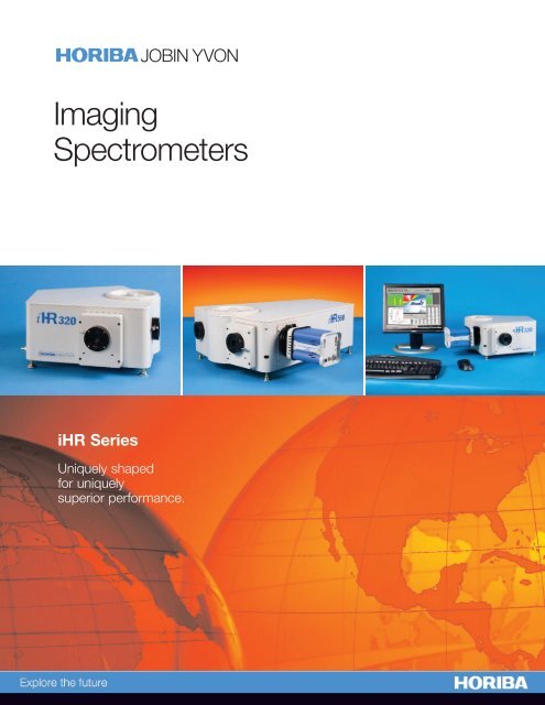
<strong>Imaging</strong><br />
<strong>Spectrometer</strong>s<br />
iHR Series<br />
Uniquely shaped<br />
for uniquely<br />
superior performance.<br />
JOBIN YVON
iHR Series <strong>Imaging</strong> <strong>Spectrometer</strong>s<br />
A Unique Shape for<br />
a Unique <strong>Spectrometer</strong><br />
The difference between iHR<br />
spectrometers and other standard<br />
Czerny-Turner spectrometers can<br />
be seen at first glance. The iHR<br />
series is not just another square box<br />
in your lab. The final design, with<br />
the unique shape of the iHR series,<br />
was adopted to provide the best<br />
solution for essential parameters in<br />
imaging spectrometers: image quality,<br />
removal of re-diffracted light and<br />
maximized optical throughput.<br />
Superior <strong>Imaging</strong><br />
Performance<br />
As an imaging spectrometer, the<br />
iHR has enhanced capabilities for use with a CCD.<br />
A toroidal mirror corrects for astigmatism, allowing the<br />
tangential (resolution optimized) and sagittal (imaging<br />
optimized) focal planes to cross at the center of the focal<br />
plane. This provides the flexibility to choose between<br />
imaging and resolution optimization (with a CCD detector)<br />
by selecting the desired detection angle. The iHR Series<br />
has one of the largest flat fields available in an imaging<br />
spectrograph. The imaging quality<br />
over the entire flat field has been<br />
maximized by using an asymmetric<br />
layout and a patented on-axis<br />
grating drive, reducing coma and<br />
other aberrations. A larger focus<br />
mirror allows the entire flat field<br />
to be used without vignetting<br />
(no throughput reduction at the<br />
edges of the focal plane).<br />
No Re-diffracted Light<br />
Re-diffracted light is light that<br />
enters the spectrometer and<br />
hits the grating twice due to<br />
an alignment of some rays of<br />
diffracted light with one of the mirrors and the<br />
grating. This light diffracts off the grating a second<br />
time and shows as a dim background illumination on<br />
the output image. In spectroscopy, this light manifests<br />
as an elevated baseline and reduced sensitivity. This<br />
set of conditions happens across different wavelength<br />
regions and is more likely to occur in conventional<br />
symmetric Czerny-Turner spectrometers. Computer<br />
optimization of the asymmetric optical path eliminates<br />
re-diffracted light through precise placement of optical<br />
component locations.<br />
The unique shape of the iHR series is a result of all<br />
these stringent design requirements.<br />
All design factors were optimized<br />
to produce the most reliable<br />
optical platform and set new industry<br />
standards never achieved before in<br />
this class of imaging spectrometers.
Flexible & Easy to Use<br />
The iHR provides a platform for spectroscopic measurements<br />
for years to come. The design of the spectrometer itself and<br />
its accompanying accessories and software enables users to<br />
customize the iHR for any experiment. This customization<br />
starts with the choice of entrance and exit ports, the library<br />
of HORIBA Jobin Yvon gratings, and the full line of<br />
spectroscopic accessories for various measurements.<br />
Internal<br />
filter wheel<br />
(optional)<br />
Choice of 2 mm slits<br />
for high resolution<br />
or 7 mm slits for<br />
high throughput<br />
Focal Length 320 mm<br />
Aperture f/4.1<br />
Spectral Range 150 to 1500 nm w/1200 g/mm grating<br />
150 nm to 40 µm w/appropriate gratings<br />
Grating Size<br />
Number of Gratings<br />
68 mm x 68 mm<br />
on Turret up to 3<br />
Flat Field Size 30 mm x 12 mm<br />
Resolution with<br />
Exit Slit and PMT 0.06 nm<br />
Wavelength Accuracy ±0.20 nm<br />
Repeatability ±0.075 nm<br />
Spectral Dispersion (@500 nm) 2.31 nm/mm<br />
Magnification 1.1<br />
Stray Light* 1.5 x 10⁻⁴ Scan Speed 160 nm/sec<br />
Step Size 0.002 nm<br />
Computer Interface Hi-Speed USB<br />
Length 417 mm (16.4 in)<br />
Width 422 mm (16.6 in)<br />
Dimensions<br />
Up to 4 ports<br />
(2 entrance and<br />
2 exit)<br />
Kinemetic<br />
turret with easy<br />
access hatch<br />
Choice of CCD or<br />
exit slit on either exit port<br />
iHR320<br />
Hi-Speed USB<br />
and additional<br />
hub port<br />
Height 192 mm (7.6 in)<br />
Optical Axis<br />
(Height from bottom 98 mm (3.9 in)<br />
of instrument)<br />
Nominal Weight 20 kg (45 lb)<br />
Purge port<br />
for UV<br />
and NIR<br />
CCD flanges for resolution<br />
or imaging optimization<br />
Easy CCD<br />
focus and<br />
alignment<br />
with external<br />
locking<br />
mechanism<br />
iHR320 and iHR550 Specifications<br />
*Stray measured at 1 nm from 514 nm laser with HORIBA Jobin Yvon Holographic Gratings.<br />
All specifications given for 1200 g/mm grating at 435 nm and are subject to change without notice.<br />
SynerJY ® , our general purpose spectroscopy software<br />
provides a platform for most measurements. Additional<br />
software possibilities are available, including our Software<br />
Development Kit and LabVIEW ® VIs.<br />
Manufacturing Excellence<br />
The iHR series is built with the highest quality materials<br />
and structure. The instrument starts as a single casting<br />
and is machined until it acquires its unique shape.<br />
This eliminates possibilities of light leaks and provides<br />
the strongest possible housing for the instrument.<br />
The electronics are installed in a light compartment<br />
separate from the light tight optical cavity,<br />
under the spectrometer. After<br />
construction, the iHR goes<br />
through a series of rigorous<br />
burn-in and testing cycles.<br />
The drive mechanism is<br />
checked and rechecked<br />
to ensure that the system<br />
meets our repeatability<br />
and accuracy requirements.<br />
iHR550<br />
Focal Length 550 mm<br />
Aperture f/6.4<br />
Spectral Range 150 to 1500 nm w/1200 g/mm grating<br />
150 nm to 40µm w/appropriate gratings<br />
Grating Size<br />
Number of Gratings<br />
76 mm x 76 mm<br />
on Turret up to 3<br />
Flat Field Size<br />
Resolution with<br />
30 mm x 12 mm<br />
Exit Slit and PMT 0.025 nm<br />
Wavelength Accuracy ±0.20 nm<br />
Repeatability ±0.075 nm<br />
Spectral Dispersion (@500 nm) 1.34 nm/mm<br />
Magnification 1.1<br />
Stray Light* 1 x 10⁻⁵ Scan Speed 160 nm/sec<br />
Step Size 0.002 nm<br />
Computer Interface Hi-Speed USB<br />
Length 648 mm (25.51 in)<br />
Width 460 mm (18.09 in)<br />
Dimensions Height<br />
Optical Axis<br />
193 mm (7.78 in)<br />
(Height from bottom<br />
of instrument)<br />
98 mm (3.9 in)<br />
Nominal Weight 28 kg (62 lb)
Seamless Integration with Synapse<br />
and Symphony ® CCD Detectors<br />
HORIBA Jobin Yvon was the first spectroscopy-based company<br />
to embrace the emerging CCD detector technology and to integrate<br />
the unique two-dimensional capabilities of these detectors<br />
with spectrometer control functions. HORIBA Jobin Yvon has<br />
15 years of experience in manufacturing CCD detectors in-house<br />
and optimizing both our CCD and spectrometer designs for<br />
unmatched spectroscopic performance.<br />
A full line of large and small format CCD chips is available to<br />
work with the spectrometers. Chip innovations from wavelength<br />
optimized back illuminated chips to deep depletion versions are<br />
available in both TE-cooled and LN-cooled housings. Due to<br />
varied parameters of the CCD, spectral coverage and resolution<br />
of the system will depend on the chosen gratings and the<br />
chosen CCD. The following table describes the expected spectral<br />
coverage and resolution of the spectrometers with different<br />
gratings and typical CCD detectors.<br />
Expected Spectral Coverage & Resolution with a Synapse or Symphony CCD **<br />
Grating<br />
(g/mm)<br />
Dispersion<br />
(nm/mm)<br />
<strong>Spectrometer</strong><br />
Mechanical<br />
Range* (nm)<br />
Spectral Coverage<br />
(nm) with<br />
26.7 mm CCD<br />
iHR320<br />
CCDs with 13.5 µm pixels CCDs with 26 µm pixels<br />
Single Pixel<br />
Spectral<br />
Coverage (nm)<br />
Typical<br />
Spectral<br />
Resolution (nm)<br />
Single<br />
Pixel Spectral<br />
Coverage (nm)<br />
Typical Spectral<br />
Resolution (nm)<br />
3600 0.20 0 to 500 5 0.003 0.01 0.005 0.02<br />
2400 0.87 0 to 750 23 0.012 0.04 0.023 0.07<br />
1800 1.38 0 to 1,000 37 0.019 0.06 0.036 0.11<br />
1200 2.31 0 to 1,500 62 0.031 0.09 0.060 0.18<br />
900 3.20 0 to 2,000 85 0.043 0.13 0.083 0.25<br />
600 4.94 0 to 3,000 132 0.067 0.20 0.128 0.39<br />
300 10.12 0 to 6,000 270 0.137 0.41 0.263 0.79<br />
150 20.43 0 to 12,000 545 0.276 0.83 0.531 1.59<br />
Grating<br />
(g/mm)<br />
Dispersion<br />
(nm/mm)<br />
<strong>Spectrometer</strong><br />
Mechanical<br />
Range* (nm)<br />
Spectral Coverage<br />
(nm) with<br />
26.7 mm CCD<br />
iHR550<br />
CCDs with 13.5 µm pixels CCDs with 26 µm pixels<br />
Single Pixel<br />
Spectral<br />
Coverage (nm)<br />
Typical<br />
Spectral<br />
Resolution (nm)<br />
Single<br />
Pixel Spectral<br />
Coverage (nm)<br />
Typical Spectral<br />
Resolution (nm)<br />
3600 0.16 0 to 500 4 0.002 0.01 0.004 0.01<br />
2400 0.53 0 to 750 14 0.007 0.02 0.014 0.04<br />
1800 0.81 0 to 1,000 22 0.011 0.03 0.021 0.06<br />
1200 1.34 0 to 1,500 36 0.018 0.05 0.035 0.10<br />
900 1.84 0 to 2,000 49 0.025 0.07 0.048 0.14<br />
600 2.83 0 to 3,000 76 0.038 0.11 0.074 0.22<br />
300 5.75 0 to 6,000 154 0.078 0.23 0.150 0.45<br />
150 11.58 0 to 12,000 309 0.156 0.47 0.301 0.90<br />
* The system’s optical range will depend not only on the grating groove density, but also the grating blaze angle and the detector’s spectral response.<br />
** Dispersion, Spectral Coverage and Resolution values are given for 500 nm. These values may vary at different wavelengths.
Unmatched Flexibility in Applications<br />
HORIBA Jobin Yvon’s Optical Spectroscopy Division provides component-based<br />
systems configured to match your experimental requirements. Our spectrometers,<br />
detectors, and accessories can be configured in a variety of different ways to<br />
provide a flexible, high performance spectroscopy platform for your laboratory.<br />
Some common configurations that we routinely provide are described below.<br />
Raman Spectroscopy<br />
Raman spectroscopy is quickly becoming a popular method<br />
for investigating chemical structures and composition.<br />
HORIBA Jobin Yvon offers full flexibility in designing a<br />
component-based Raman detection set-up with choice<br />
of iHR spectrometers and Synapseor Symphony CCD<br />
and InGaAs detectors. Our systems<br />
are best suited for researchers<br />
wanting maximum flexibility<br />
in implementing their own<br />
collection optics, connecting<br />
to existing microscopes,<br />
or for budget limited<br />
researchers needing<br />
high sensitivity<br />
detection systems that can be<br />
expanded and upgraded in the future.<br />
HORIBA Jobin Yvon’s specialized<br />
Raman Division offers a full line of<br />
dedicated, and fully characterized<br />
Raman spectrometers.<br />
Photoluminescence (PL)<br />
Photoluminescence is a simple yet powerful<br />
technique for characterizing semiconductor<br />
materials. An iHR550 equipped with<br />
a cooled CCD detector for the<br />
range of 400-1000 nm,<br />
and a cooled InGaAs<br />
detector for the<br />
800-1600 nm range,<br />
is an excellent<br />
general purpose<br />
photoluminescence<br />
measurement<br />
system. Separate<br />
optical configurations can<br />
be designed for room temperature<br />
PL and low-temperature PL using the<br />
same iHR spectrometer. iHR spectrometers provide<br />
the flexibility to change experiments and optical<br />
configurations to meet your needs.<br />
HORIBA Jobin Yvon’s<br />
Sales and Applications staff<br />
can provide expert advice<br />
on configuring a system for<br />
your specific experiment.<br />
Absorption / Transmission / Reflectance<br />
Absorption, Transmission, and Reflectance spectroscopy techniques<br />
are commonly used for determining the properties of materials.<br />
The modularity of an HORIBA Jobin Yvon spectroscopy<br />
system outperforms a traditional UV-VIS spectrophotometer<br />
by allowing you to expand your experiment capabilities.<br />
The automated triple grating turret coupled<br />
with our motorized order sorting filter wheel,<br />
dual exit ports of the iHR320, and a wide<br />
variety of light sources and detectors<br />
give the flexibility needed to<br />
cover all wavelength ranges<br />
from 180 nm to 20 microns.<br />
Fluorescence<br />
With HORIBA Jobin Yvon<br />
spectroscopy components,<br />
you can design a custom<br />
fluorometer using iHR spectrometers<br />
as the excitation and emission<br />
spectrometers with a choice of excitation sources,<br />
sample compartments and detectors from our full line of products<br />
and accessories. Complete system control is available<br />
through our SynerJY ® software.<br />
HORIBA Jobin Yvon’s<br />
specialized Fluorescence<br />
Division offers a full line<br />
of dedicated, fully<br />
characterized spectrofluorometers<br />
and both timedomain<br />
and frequencydomain<br />
fluorescence lifetime<br />
instruments, featuring the world’s most sensitive<br />
instruments for research and analytical environments.<br />
Plasma / Emission Analysis<br />
Simultaneous recording of spectra at multiple locations in a<br />
plasma can provide critical information about spatially varying<br />
phenomena. A fiber with multiple inputs can collect light<br />
from different points in the plasma and arrange<br />
the signals into a line of points at the entrance slit<br />
of the spectrograph. Taking advantage<br />
of the imaging capability of an<br />
iHR spectrograph and<br />
Synapse CCD system,<br />
the spatially separated<br />
data is collected<br />
uniquely on the CCD<br />
and represents independent<br />
optical emission<br />
spectra<br />
from different fiber<br />
collection points.
Ordering Information<br />
iHR320 iHR320 Base Unit<br />
iHR550 iHR550 Base Unit<br />
MAI-IR iHR Series Resolution Array Adapter<br />
for HORIBA Jobin Yvon’s CCDs<br />
MAI-II iHR320 <strong>Imaging</strong> Array Adapter for<br />
HORIBA Jobin Yvon CCDs<br />
MAI-I5I iHR550 <strong>Imaging</strong> Array Adapter for<br />
HORIBA Jobin Yvon CCDs<br />
MAI-ICM iHR Array Adapter for C-Mount Detectors<br />
iHR320 Computer Controlled Slits<br />
MSL-I3FN2 (-I3FX2)<br />
Front Entrance (Exit) Slit: 0 to 2 mm in 2 µm steps<br />
MSL-I3SN2 (-I3SX2)<br />
Side Entrance (Exit) Slit: 0 to 2 mm in 2 µm steps<br />
MSL-I3FN7 (-I3FX7)<br />
Front Entrance (Exit) Slit: 0 to 7 mm in 6.25 µm steps<br />
MSL-I3SN7 (-I3SX7)<br />
iSide Entrance (Exit) Slit: 0 to 7 mm in 6.25 µm steps<br />
iHR550 Computer Controlled Slits<br />
MSL-I5FN2 (-I5FX2)<br />
Front Entrance (Exit) Slit: 0 to 2 mm in 2 µm steps<br />
MSL-I5SN2 (-I5SX2)<br />
Side Entrance (Exit) Slit: 0 to 2 mm in 2 µm steps<br />
MSL-I5FN7 (-I5FX7<br />
Front Entrance (Exit) Slit: 0 to 7 mm in 6.25 µm steps<br />
MSL-I5SN7 (-I5SX7)<br />
Side Entrance (Exit) Slit: 0 to 7 mm in 6.25 µm steps<br />
MSL-IANM Motorized Swing Entrance Mirror<br />
MSL-IAXM Motorized Swing Exit Mirror<br />
MGM-IT Additional Interchangeable Triple Grating Turret<br />
for iHR320<br />
MGM-I5T Additional Interchangeable Triple Grating Turret<br />
for iHR550<br />
MSH-ICF Internal CCD Shutter for an iHR Front Entrance Port<br />
MSH-ICS Internal CCD Shutter for an iHR Side Entrance Port<br />
UVCOAT-MIR UV coating of spectrometer mirrors for increased<br />
throughput between 200 nm – 300 nm<br />
AUCOAT-MIR Gold coating of spectrometer mirrors for<br />
increased throughput in the NIR and IR.<br />
Cuts out wavelengths below 500 nm<br />
iHR Accessories<br />
AFW-IHR iHR320 Internal Filter Wheel, 6 x 25.4 mm<br />
(1 inch) filter positions<br />
AFW-C6PM External Filter Wheel, 6 x 25.4 mm<br />
(1 inch) filter positions<br />
MHR-FSA Filter Slide, 3 x 25.4 mm (1 inch) filter positions<br />
ACH-C Optical Chopper for use with IR detectors<br />
and Lock-In Amplifiers<br />
AFO-XY XY adjustable Fiber Optic Adapter<br />
for 10 mm and 1⁄4 inch ferrules<br />
MHR-OFAE Direct Fiber mount, 1⁄4” inch ferrule<br />
MHR-OFAM Direct Fiber mount, 10 mm ferrule<br />
23022640 1x <strong>Imaging</strong> Fiber Adapter<br />
ASC-VIS SampleMax Sample Compartment<br />
ASC-UV SampleMax Sample Compartment<br />
optimized for UV<br />
DPM-HV UV-VIS Photomultiplier Tube (PMT)<br />
and Housing<br />
DSS Detectors Solid State Detectors including Si, Ge,<br />
InGaAs, InAs, PBs, PbSe & MCT<br />
1427B Solid State Detector Interface<br />
HORIBA Jobin Yvon was the first<br />
spectroscopy based company to embrace<br />
the emerging CCD detector technology<br />
and to integrate the unique two dimensional<br />
capabilities of these detectors with<br />
spectrometer control functions.