Battery System ZB-S - CEAG
Battery System ZB-S - CEAG
Battery System ZB-S - CEAG

Create successful ePaper yourself
Turn your PDF publications into a flip-book with our unique Google optimized e-Paper software.
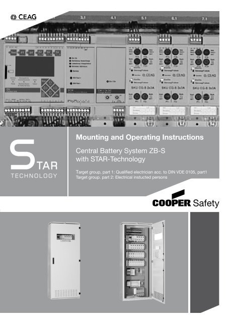
Mounting and Operating Instructions<br />
Central <strong>Battery</strong> <strong>System</strong> <strong>ZB</strong>-S<br />
with STAR-Technology<br />
Target group, part 1: Qualified electrician acc. to DIN VDE 0105, part1<br />
Target group. part 2: Electrical instucted persons
Assembly and Operating Instructions<br />
Central <strong>Battery</strong> <strong>System</strong> <strong>ZB</strong>-S with STAR-Technology<br />
Index<br />
PART 1<br />
1. General Information<br />
1.1 Description of Symbols . . . . . . . . . . . . . . . . . . . . . . . 5<br />
1.2 Information regarding these Instructions . . . . . . . . . . . . . . . . . . . 5<br />
1.3 Further Applicable Documents . . . . . . . . . . . . . . . . . . . . . 5<br />
1.4 Liability and Guarantee . . . . . . . . . . . . . . . . . . . . . . . 5<br />
1.5 Copyright Protection . . . . . . . . . . . . . . . . . . . . . . . . 6<br />
1.6 Spare Parts . . . . . . . . . . . . . . . . . . . . . . . . . . 6<br />
1.7 Recycling . . . . . . . . . . . . . . . . . . . . . . . . . . . 6<br />
2. Safety<br />
2.1 Inteded Use . . . . . . . . . . . . . . . . . . . . . . . . . . 6<br />
2.2 Contents of Operating Instructions . . . . . . . . . . . . . . . . . . . . 7<br />
2.3 Changes and Modifications to the <strong>System</strong> . . . . . . . . . . . . . . . . . . 7<br />
2.4 Responsibility of the Operator . . . . . . . . . . . . . . . . . . . . . 7<br />
2.5 Personnel Requirements . . . . . . . . . . . . . . . . . . . . . . . 7<br />
2.6 Operational Safety . . . . . . . . . . . . . . . . . . . . . . . . 7<br />
2.7 Personal Protective Equipment . . . . . . . . . . . . . . . . . . . . . 7<br />
3. Technical Data<br />
3.1 Data Sheet for <strong>ZB</strong>-S/26 . . . . . . . . . . . . . . . . . . . . . . . 8<br />
3.2 Data Sheet for <strong>ZB</strong>-S/18 . . . . . . . . . . . . . . . . . . . . . . . 9<br />
3.3 Data Sheet for <strong>ZB</strong>-S/LAD . . . . . . . . . . . . . . . . . . . . . . 10<br />
3.4 Data Sheet for <strong>ZB</strong>-S/10C . . . . . . . . . . . . . . . . . . . . . . . 11<br />
3.5 Data Sheet for <strong>ZB</strong>-S/10C6 . . . . . . . . . . . . . . . . . . . . . . 12<br />
3.6 Data Sheet for <strong>ZB</strong>-S/18C6 . . . . . . . . . . . . . . . . . . . . . . 13<br />
3.7 Data Sheet for <strong>ZB</strong>-S/26C6 . . . . . . . . . . . . . . . . . . . . . . 14<br />
3.8 Data Sheet for <strong>ZB</strong>-S/18C3 . . . . . . . . . . . . . . . . . . . . . . 15<br />
3.9 Data Sheet for <strong>ZB</strong>-S/10C3 . . . . . . . . . . . . . . . . . . . . . . 16<br />
3.10 Data Sheet for <strong>ZB</strong>-S/2C3 . . . . . . . . . . . . . . . . . . . . . . . 17<br />
3.11 Data Sheet for US-S/36 . . . . . . . . . . . . . . . . . . . . . . . 18<br />
3.12 Data Sheet for US-S/28 . . . . . . . . . . . . . . . . . . . . . . . 19<br />
3.13 Data Sheet for US-S/21 . . . . . . . . . . . . . . . . . . . . . . . 20<br />
3.14 Data Sheet for US-S/13 . . . . . . . . . . . . . . . . . . . . . . . 21<br />
3.15 Data Sheet for US-S/5 . . . . . . . . . . . . . . . . . . . . . . . 22<br />
3.16 Data Sheet for US-S/SOU2 . . . . . . . . . . . . . . . . . . . . . . 23<br />
3.17 Data Sheet for US-S/SOU1 . . . . . . . . . . . . . . . . . . . . . . 23<br />
3.18 Data Sheet for ESF-E30/13S . . . . . . . . . . . . . . . . . . . . . . 24<br />
3.19 Data Sheet for ESF-E30/13S-P . . . . . . . . . . . . . . . . . . . . . 25<br />
3.20 Data Sheet for ESF-E30/28S . . . . . . . . . . . . . . . . . . . . . . 26<br />
3.21 Data Sheet for ESF-E30/28S-P . . . . . . . . . . . . . . . . . . . . . 27<br />
4. Construction and Function<br />
4.1 Example of Control Cabinet-Construction (<strong>ZB</strong>-S/26) . . . . . . . . . . . . . . . 28<br />
4.2 Product Description . . . . . . . . . . . . . . . . . . . . . . . . 29<br />
4.3 Operation Modes . . . . . . . . . . . . . . . . . . . . . . . . . 29<br />
4.4 Overview over the Components . . . . . . . . . . . . . . . . . . . . . 30<br />
4.4.1 Control Module <strong>ZB</strong>-S . . . . . . . . . . . . . . . . . . . . . . . . 30<br />
4.4.2 DC/DC Converter.2 . . . . . . . . . . . . . . . . . . . . . . . . 34<br />
2<br />
<strong>CEAG</strong> Notlichtsysteme GmbH
Assembly and Operating Instructions<br />
Central <strong>Battery</strong> <strong>System</strong> <strong>ZB</strong>-S with STAR-Technology<br />
Index<br />
4.4.2.1 AC-Module . . . . . . . . . . . . . . . . . . . . . . . . . . 34<br />
4.4.3 Baterie Control Modul BCM . . . . . . . . . . . . . . . . . . . . . . 35<br />
4.4.4 Charging module CM 1.7 A and CM 3.4 A . . . . . . . . . . . . . . . . . . 35<br />
4.4.5 Circuit change-over modules overview (SKUs) . . . . . . . . . . . . . . . . . 36<br />
4.4.6 Inverter SWR 150 . . . . . . . . . . . . . . . . . . . . . . . . . 42<br />
4.4.6.1 Determination of current consumption value from the battery . . . . . . . . . . . . . 46<br />
4.4.7 Event printer PD3 . . . . . . . . . . . . . . . . . . . . . . . . . 48<br />
4.4.8 Relay module CG IV and CG V . . . . . . . . . . . . . . . . . . . . . 49<br />
4.4.9 F3 remote indication . . . . . . . . . . . . . . . . . . . . . . . . 50<br />
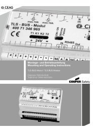
4.4.10 External TLS-bus-module . . . . . . . . . . . . . . . . . . . . . . 51<br />
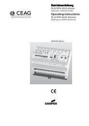
4.4.11 External DLS/3Ph-bus-module and ext. DLS/3Ph-bus-module inverse . . . . . . . . . . . 52<br />
4.4.12 Webmodule . . . . . . . . . . . . . . . . . . . . . . . . . . 54<br />
4.4.13 Bus-Technology according to RS 485 or CG-S-Bus . . . . . . . . . . . . . . . . 55<br />
4.4.14 Batteries for emergency power supply . . . . . . . . . . . . . . . . . . . 56<br />
4.5 Label of <strong>ZB</strong>-S . . . . . . . . . . . . . . . . . . . . . . . . . . 57<br />
4.6 Example of Installation . . . . . . . . . . . . . . . . . . . . . . . 58<br />
5. Transport, Packaging and Storage<br />
5.1 Safety Notes . . . . . . . . . . . . . . . . . . . . . . . . . . 60<br />
5.2 Transport inspection . . . . . . . . . . . . . . . . . . . . . . . . 60<br />
5.3 Packaging . . . . . . . . . . . . . . . . . . . . . . . . . . 60<br />
5.4 Storage . . . . . . . . . . . . . . . . . . . . . . . . . . . 61<br />
6. Installation<br />
6.1 Safety Notes . . . . . . . . . . . . . . . . . . . . . . . . . . 62<br />
6.2 Assembly . . . . . . . . . . . . . . . . . . . . . . . . . . . 63<br />
6.3 Installation . . . . . . . . . . . . . . . . . . . . . . . . . . 64<br />
6.4 Connection to mains . . . . . . . . . . . . . . . . . . . . . . . . 64<br />
6.4.1 Connection to mains supply of a <strong>ZB</strong>-S station . . . . . . . . . . . . . . . . . 64<br />
6.4.2 Connection to mains of substations US-S . . . . . . . . . . . . . . . . . . 65<br />
6.5 Connection to battery power supply . . . . . . . . . . . . . . . . . . . . 65<br />
6.5.1 Connection to battery power supply for a <strong>ZB</strong>-S station . . . . . . . . . . . . . . . 66<br />
6.5.2 Connecting the <strong>Battery</strong> supply of a US-S substation . . . . . . . . . . . . . . . 67<br />
6.6 Connection of temperature sensor . . . . . . . . . . . . . . . . . . . . 67<br />
6.7 Connection and installation of internal modules . . . . . . . . . . . . . . . . . 68<br />
6.8 Connection and installation of external modules . . . . . . . . . . . . . . . . 68<br />
6.8.1 DLS/3Ph-Bus-Module . . . . . . . . . . . . . . . . . . . . . . . 69<br />
6.8.2 TLS-Bus-Module . . . . . . . . . . . . . . . . . . . . . . . . . 69<br />
6.8.3 <strong>CEAG</strong> 3-phase monitors with 24V current loop . . . . . . . . . . . . . . . . . 70<br />
6.8.4 Completing Assembly . . . . . . . . . . . . . . . . . . . . . . . 70<br />
7. Commissioning and other work<br />
7.1 Safety Notes . . . . . . . . . . . . . . . . . . . . . . . . . . 71<br />
7.2 Checking all connections. . . . . . . . . . . . . . . . . . . . . . . 71<br />
7.3 Voltage measurements . . . . . . . . . . . . . . . . . . . . . . . 71<br />
7.4 Insulation Testing . . . . . . . . . . . . . . . . . . . . . . . . . 71<br />
7.5 Checking / replacing of fuses . . . . . . . . . . . . . . . . . . . . . 72<br />
7.5.1 Checking the fuses of the mains and/or battery power supply . . . . . . . . . . . . . 72<br />
7.5.2 Setting of float charge voltage of the <strong>Battery</strong> Control Module (BCM) . . . . . . . . . . . 73<br />
7.5.3 Checking the fuses of SKU modules . . . . . . . . . . . . . . . . . . . . 73<br />
3<br />
<strong>CEAG</strong> Notlichtsysteme GmbH
Assembly and Operating Instructions<br />
Central <strong>Battery</strong> <strong>System</strong> <strong>ZB</strong>-S with STAR-Technology<br />
Index<br />
7.6 Checking and replacing internal modules . . . . . . . . . . . . . . . . . . 74<br />
7.7 Checking and replacing external modules . . . . . . . . . . . . . . . . . . 74<br />
7.8 Powering up the system . . . . . . . . . . . . . . . . . . . . . . . 74<br />
PART 2<br />
8. Operating<br />
8.1 Safety Notes . . . . . . . . . . . . . . . . . . . . . . . . . . 75<br />
8.2 General information about operating . . . . . . . . . . . . . . . . . . . . 75<br />
8.3 Controls and displays on the modules . . . . . . . . . . . . . . . . . . . 76<br />
8.3.1 Control module CU CG-S . . . . . . . . . . . . . . . . . . . . . . 76<br />
8.3.2 DC/DC Converter . . . . . . . . . . . . . . . . . . . . . . . . . 76<br />
8.3.3 Batterie Control Modul (BCM) and charging module CM 1,7 A, CM 3,4 A . . . . . . . . . . 77<br />
8.3.4 SKU´s of the final circuits . . . . . . . . . . . . . . . . . . . . . . . 78<br />
8.3.5 Data printer . . . . . . . . . . . . . . . . . . . . . . . . . . 78<br />
8.4 Operating the CU CG-S control module . . . . . . . . . . . . . . . . . . . 78<br />
8.4.1 Menu 1: “Test & Status Menu” . . . . . . . . . . . . . . . . . . . . . 82<br />
8.4.2 Menu 2: “Block & reset alarms” . . . . . . . . . . . . . . . . . . . . . 84<br />
8.4.3 Menu 3: “Basic settings” . . . . . . . . . . . . . . . . . . . . . . . 85<br />
8.4.4 Menu 4: “DLS/TLS setup” . . . . . . . . . . . . . . . . . . . . . . 91<br />
8.4.5 Menu 5: “Circuit setup” . . . . . . . . . . . . . . . . . . . . . . . 92<br />
8.4.6 Menu 6 “Luminaire setup” . . . . . . . . . . . . . . . . . . . . . . 95<br />
8.4.7 Menu 7 “Logbooksetup” . . . . . . . . . . . . . . . . . . . . . . . 97<br />
8.4.8 Menu 8 “Send ServicePinMsg” . . . . . . . . . . . . . . . . . . . . . 97<br />
9. Failures<br />
9.1 Interference immunity by screening . . . . . . . . . . . . . . . . . . . . 98<br />
9.1.1 Cable screens . . . . . . . . . . . . . . . . . . . . . . . . . 98<br />
9.1.2 Screen connection . . . . . . . . . . . . . . . . . . . . . . . . 98<br />
9.1.3 The fail-safe system . . . . . . . . . . . . . . . . . . . . . . . . 99<br />
10. Maintenance / Checking<br />
10.1 Safety Notes . . . . . . . . . . . . . . . . . . . . . . . . . 100<br />
10.2 General information to maintenance / checking . . . . . . . . . . . . . . . . 100<br />
10.3 Enabling of end circuits with maintenance work . . . . . . . . . . . . . . . . 101<br />
10.4 ESF-E30 Activate fan for maintenance work . . . . . . . . . . . . . . . . . 101<br />
Appendix . . . . . . . . . . . . . . . . . . . . . . . . . . . from 102<br />
4<br />
<strong>CEAG</strong> Notlichtsysteme GmbH
Assembly and Operating Instructions<br />
Central <strong>Battery</strong> <strong>System</strong> <strong>ZB</strong>-S with STAR-Technology<br />
Important Notes<br />
1. General Information<br />
1.1 Description of Symbols<br />
Important safety notes are marked with symbols in these instructions. These stated notes have to be observed<br />
essentially.<br />
WARNING! DANGER! RISK OF INJURY OR DEATH!<br />
Signifies notes which, when not observed, can cause impairment of health, (steady) injury or death.<br />
ATTENTION! DAMAGE TO PROPERTY!<br />
Signifies notes which, when not observed, can cause damage to property and even the collapse of the<br />
system.<br />
NOTE!<br />
Includes important hints and advice that is important for failure-free operation.<br />
1.2 Information regarding these Instructions<br />
These operating instructions show the safe and proper handling with the system. The stated safety notes<br />
and instructions as well as the local accident prevention- and safety regulations have to be observed.<br />
Before working with the system, the instructions have to be read carefully, especially the chapter „Safety Instructions“.<br />
The figures and circuit diagrams contained in these assembly and operating instructions are in part intended only<br />
to illustrate the products which are described. In all cases where<br />
r dimensionally accurate work is required, or<br />
r accurate drawings or circuit diagrams that reflect the specifics of the site are required,<br />
the drawings and plans that have been created specially for the lighting system must be followed.<br />
1.3 Further Applicable Documents<br />
In the systems, components from other manufacturers are mounted. These purchasing-components are checked<br />
according to danger evaluation by the manufacturer. They declare the compliance of the construction with the<br />
European and national regulations.<br />
1.4 Liability and Guarantee<br />
All information and notes in these instructions are compiled according to the valid regulations, the state of the art,<br />
our long-standing knowledge and experience.<br />
Keep the instructions near to the system, accessible for every person working with the system and at all times.<br />
Read the instructions carefully before working on and with the system!<br />
<strong>CEAG</strong> Notlichtsysteme GmbH can accept no liability and/or give no warranty in respect of any defects that may<br />
occur with the supply and intallation of <strong>CEAG</strong> emergency lighting systems and luminaires on the basis of other<br />
standards and regulations which are mandatory in complete installation packages in conjunction with <strong>CEAG</strong> products.<br />
You must also comply with all statutes, standards and directives of the country in which the system is installed<br />
and operated.<br />
<strong>CEAG</strong> will give no warranty or accept any liability for damage or consequential damage caused as a result of<br />
r improper use,<br />
r failure to comply with regulations and codes of conduct for the safe operation of the system,<br />
r unauthorised or inexpert modifications to the connections and settings of the system, or to the programming<br />
of the system,<br />
r operating proscribed or unsuitable devices or groups of devices in the <strong>ZB</strong>-S system.<br />
5<br />
<strong>CEAG</strong> Notlichtsysteme GmbH
Assembly and Operating Instructions<br />
Central <strong>Battery</strong> <strong>System</strong> <strong>ZB</strong>-S with STAR-Technology<br />
Important Notes<br />
1.5 Copyright Protection<br />
All information from the contents, text, drawings, pictures and further representations are protected with regards<br />
to copyright.<br />
1.6 Spare Parts<br />
Only use original spare parts from the manufacturer<br />
ATTENTION!<br />
Wrong or faulty spare parts can cause damage, failure or collapse of the system.<br />
When using unapproved spare parts, all guarantee, service, damage and liability claims are forfeited.<br />
1.7 Recycling<br />
Packing materials are not refuse, they are valuable materials and should be re-used or recycled.<br />
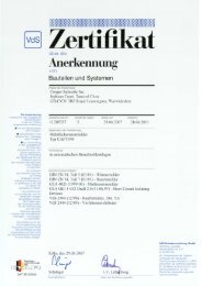
<strong>CEAG</strong> has been awarded the Recycling Certificate of INTERSEROH GmbH. The contract number<br />
is 85405. It guarantees that the packaging materials which it covers are properly recycled and that<br />
all the requirements of the German Packaging Code are complied with.<br />
INTERSEROH collection points are required to dispose of <strong>CEAG</strong> packaging free of charge.<br />
Batteries and electronic components contain materials that can damage health and the environment if not properly<br />
disposed of. Dispose of old batteries and electronic components in accordance with national guidelines and<br />
regulations.<br />
2. Safety<br />
The central battery system is designed and built in conformity with the latest technical rules at the time of its development<br />
and production, so it is safe to operate. Danger maybe presented by the device, if it will be used for other<br />
than the intended purpose and by unskilled personnel.<br />
WARNING!<br />
When planning a lighting system with a <strong>ZB</strong>-S system you first establish wether the proposed electrical installations<br />
satisfy local environmental conditions.<br />
Special environmental conditions (e. g. areas subject to explosion hazards or areas with an aggressive<br />
atmosphere) call for special equipments and installations.<br />
Only operate the system and parts connected to it when they are in a technically perfect condition, and comply<br />
with<br />
r the safety and hazard information given in these assembly and operating instructions,<br />
r the work and safety instructions issued by the operator of the system,<br />
r the installation and operating data given in „3 Technical data“ and in the <strong>CEAG</strong> Catalogue.<br />
Faults that can affect the operation or safety of the system must be reported immediately to the company officers<br />
and remediated.<br />
2.1 Inteded Use<br />
The <strong>ZB</strong>-S and US-S Central <strong>Battery</strong> <strong>System</strong>s are exclusively designed to monitor and control a lighting system<br />
with general and emergency lighting.<br />
Their operation is program controlled. They must be programmed and set up by engineers with specialist knowledge<br />
of the legal and technical requirements governing the assembly and operation of lighting systems.<br />
The operating safety can only be guaranteed by intended use of the systems.<br />
ATTENTION!<br />
Every use beyond or different than the intended purpose is prohibited, and therefore not in accordance with<br />
regulations!<br />
6<br />
<strong>CEAG</strong> Notlichtsysteme GmbH
Assembly and Operating Instructions<br />
Central <strong>Battery</strong> <strong>System</strong> <strong>ZB</strong>-S with STAR-Technology<br />
Important Notes<br />
2.2 Contents of Operating Instructions<br />
Every person, ordered to work with the system, has to read the instructions carefully to understand them before<br />
work begins. This takes also place when the person has already worked with a similar kind of battery or was instructed<br />
by the manufacturer.<br />
2.3 Changes and Modifications to the <strong>System</strong><br />
To avoid danger and to assure optimum performance, changes and modifications to the system are not allowed,<br />
except when the manufacturer has approved them.<br />
Any work involved in extensions, conversions or repairs and which is not described in this manual must be carried<br />
out by specially trained technical and service personnel (of the manufacturer <strong>CEAG</strong> or of <strong>CEAG</strong>-authorised distribution<br />
and service contractors)!<br />
2.4 Responsibility of the Operator<br />
Keep the instructions near to the system, accessible for every person working with the system and at all times.<br />
The <strong>System</strong> must be in a proper and safe condition when using it. <strong>System</strong> has to be checked for intactness before<br />
using it.<br />
Adhere to the information of the instructions completely!<br />
2.5 Personnel Requirements<br />
Only authorised and skilled personnel are allowed to work on and with the system. The personnel must have received<br />
instructions regarding the existing danger.<br />
Skilled personnel refers to those with expert training, with knowledge and experience as well as knowledge of the<br />
relevant regulations. He should be able to evaluate his work and recognize the presence of danger.<br />
Personnel without the necessary knowledge must<br />
r have received qualified and proper training,<br />
r get their tasks and activities by full description for complete understanding<br />
r carry out the activities under the supervision and control of skilled and qualified personnel.<br />
2.6 Operational Safety<br />
Observing the stated safety instructions and regulations can avoid damage to property and people when working<br />
with the system.<br />
However the following organisational measurements must be specified in writing and be kept:<br />
r Duties of information and reporting (start, duration, end of the work)<br />
r Safety measures while the work is being carried out: e. g. standby lighting, power supply isolation and lockout<br />
(e. g. removing the fuses, key-operated switch, safety signage)<br />
r Safety equipment for the personnel carrying out the work on the plant (s. chapter 2.7)<br />
r Safety equipment providing protection from hazards caused by adjacent plant (e. g. safety grilles, barriers,<br />
making safe of roads)<br />
Attend to the ESD-protection during working at the system!<br />
The applicable work and safety regulations are set out in these assembly and operating instructions, and in<br />
r the management´s internal organisational instructions (example see above)<br />
r and the general and specialist technical guidelines and accident prevention regulations.<br />
2.7 Personal Protective Equipment<br />
When working on and with the system it is necessary to wear:<br />
r Protective Clothes<br />
Close fitting protective clothes (low tensile strength, no wide arms,<br />
no rings and further jewelry, etc).<br />
r Safety Boots<br />
Boots electrostatic conductive acc. to EN 345<br />
and to protect against heavy falling parts.<br />
7<br />
<strong>CEAG</strong> Notlichtsysteme GmbH
Assembly and Operating Instructions<br />
Central <strong>Battery</strong> <strong>System</strong> <strong>ZB</strong>-S with STAR-Technology<br />
Technical Data<br />
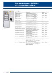
3. Technical Data<br />
3.1 Data Sheet for <strong>ZB</strong>-S/26<br />
Type of system : <strong>ZB</strong>-S 26<br />
Construction : Sheet steel cabinet with partial viewing window<br />
in the door<br />
Height : 2050 mm<br />
Width : 800 mm<br />
Depth : 400 mm<br />
Weight without battery : approx. 180 kg<br />
Insulation class : I<br />
Degree of protection : IP 21<br />
External painting : Structure powder laquer RAL 7035 light grey<br />
Cable entry : at the top (prepunched roof sheeting)<br />
: at the bottom (open bottom with propping<br />
tracks on the side)<br />
Hinge : right<br />
Mains rated voltage : 400V AC, 50/60 Hz<br />
<strong>Battery</strong> rated voltage : 216V DC<br />
<strong>Battery</strong> capacity (C10; 1.8V/Z; +20°C) : 23.3 - 245 Ah<br />
Type of battery : Lead acid battery, 10 years service life at +20°C<br />
acc. to IEC 486<br />
Duration of emergency lighting : 1 h or 3 h<br />
Recharging time : 12 h acc. to DIN EN 50171<br />
Ambient temperature operation : -5°C up to +35°C<br />
Opt. ambient temperature battery : +20°C<br />
(please attend to the attachted operating and installation instructions)<br />
Mains feed in (max. 50mm²) : Q1<br />
<strong>Battery</strong> feed in (max. 50mm²) : Q2<br />
Max. 80 circuits (max. 4 mm²)* : X1.1, X2.1, X3.1, X4.1<br />
Marshalling mains (max. 16mm²) : F10 - F15<br />
Marshalling battery (max. 16mm²) : F30 - F35, F50 - F55<br />
Addresses optional places DLS-3Ph, TLS (max. 2,5mm²): customised<br />
Connection to ext. control switch (max. 4mm²)** : X1.1.S1-S2<br />
Connection to 24V current loop (max. 4mm²)** : X1.1.S3-S4<br />
Connection to potential-free signal contacts<br />
(max.4mm²)** : X1.1 C0, 14, 12, 24, 22, 34, 32, C1, 44, 54<br />
Connection to CG-S Bus (max. 4mm²)** : X1.1.A-B<br />
Connection to RS485 Bus (max. 4mm²)** : X1.1.RS485.A-B<br />
Connection to 24V analog output (max. 4mm²)** : X1.1.+24V Out--24V Out<br />
Connection to 24V analog input (max.4mm²)** : X1.1 Z11, Z12, Z21, Z22, Z31, Z32, Z41, Z42<br />
* Max. 2.5mm² flexible with wiring sleeve. The final circuits get wired customised.<br />
** Two strands to max. 0.5 mm² with twin wire end sleeve can be clamped in a<br />
clamp spring terminal.<br />
8<br />
interior side view, left front view, open<br />
interior side view, right<br />
<strong>CEAG</strong> Notlichtsysteme GmbH
Assembly and Operating Instructions<br />
Central <strong>Battery</strong> <strong>System</strong> <strong>ZB</strong>-S with STAR-Technology<br />
Technical Data<br />
3.2 Data Sheet for <strong>ZB</strong>-S/18<br />
Type of system : <strong>ZB</strong>-S 18<br />
Construction : Sheet steel cabinet with partial viewing window<br />
in the door<br />
Height : 2050 mm<br />
Width : 800 mm<br />
Depth : 400 mm<br />
Weight without battery : approx. 170 kg<br />
Insulation class : I<br />
Degree of protection : IP 21<br />
External painting : Structure powder laquer RAL 7035 light grey<br />
Cable entry : at the top (prepunched roof sheeting)<br />
: at the bottom (open bottom with propping<br />
tracks on the side)<br />
Hinge : right<br />
Mains rated voltage : 400/230V AC, 50/60 Hz<br />
<strong>Battery</strong> rated voltage : 216V DC<br />
<strong>Battery</strong> capacity (C10; 1.8V/Z; +20°C) : 23.3 - 245 Ah<br />
Type of battery : Lead acid battery, 10 years service life at +20°C<br />
acc. to IEC 486<br />
Duration of emergency lighting : 1 h or 3 h<br />
Recharging time : 12 h acc. to DIN EN 50171<br />
Ambient temperature operation : -5°C up to +35°C<br />
Opt. ambient temperature battery : +20°C<br />
(please attend to the attached operating and installation instructions)<br />
Mains feed in (max. 50mm²) : Q1<br />
<strong>Battery</strong> feed in (max. 50mm²) : Q2<br />
Max. 68 circuits (max. 4mm²)* : X1.1, X2.1, X3.1<br />
Marshalling mains (max. 16mm²) : F10 - F15<br />
Marshalling battery (max. 16mm²) : F30 - F35, F50 - F55<br />
Addresses optional places DLS-3Ph, TLS (max. 2.5mm²): customised<br />
Connection to ext. control switch (max. 4mm²)** : X1.1.S1-S2<br />
Connection to 24V current loop (max. 4mm²)** : X1.1.S3-S4<br />
Connection to potential-free signal contacts<br />
(max.4mm²)** : X1.1 C0, 14, 12, 24, 22, 34, 32, C1, 44, 54<br />
Connection to CG-S Bus (max. 4mm²)** : X1.1.A-B<br />
Connection to RS485 Bus (max. 4mm²)** : X1.1.RS485.A-B<br />
Connection to 24V analog output (max. 4mm²)** : X1.1.+24V Out--24V Out<br />
Connection to 24V analog input(max.4mm²)** : X1.1 Z11, Z12, Z21, Z22, Z31, Z32, Z41, Z42<br />
* Max. 2.5mm² flexible with wiring sleeve. The final circuits get wired customised.<br />
** Two strands to max. 0.5 mm² with twin wire end sleeve can be clamped in a<br />
clamp spring terminal.<br />
9<br />
interior side view, left front view, open<br />
interior side view, right<br />
<strong>CEAG</strong> Notlichtsysteme GmbH
Assembly and Operating Instructions<br />
Central <strong>Battery</strong> <strong>System</strong> <strong>ZB</strong>-S with STAR-Technology<br />
Technical Data<br />
3.3 Data Sheet for <strong>ZB</strong>-S/LAD<br />
Type of system : <strong>ZB</strong>-S LAD (Cable entry from top)<br />
Construction : Sheet steel cabinet with a door made of sheet<br />
Height : 2050 mm<br />
Width : 800 mm<br />
Depth : 400 mm<br />
Weight without battery : approx. 170 kg<br />
Insulation class : I<br />
Degree of protection : IP 21<br />
External painting : Structure powder laquer RAL 7035 light grey<br />
Cable entry : at the top (prepunched roof sheeting)<br />
: at the bottom (open bottom with propping<br />
tracks on the side)<br />
Hinge : right<br />
Mains rated voltage : 400/230V AC, 50/60 Hz<br />
<strong>Battery</strong> rated voltage : 216V DC<br />
<strong>Battery</strong> capacity (C10; 1.8V/Z; +20°C) : 23.3 - 308 Ah<br />
Type of battery : Lead acid battery,10 years service life at +20°C<br />
acc. to IEC 486<br />
Duration of emergency lighting : 1 h or 3 h<br />
Recharging time : 12 h acc. to DIN EN 50171<br />
Ambient temperature operation : -5°C up to +35°C<br />
Opt. ambient temperature battery : +20°C<br />
(please attend to the attached operating and installation instructions)<br />
Mains feed in (max. 50mm²) : Q1, X7<br />
<strong>Battery</strong> feed in (max. 50mm²) : Q2, X9<br />
Max. 4 circuits (max. 4mm²)* : X11<br />
Marshalling mains (max. 16mm²) : F10 - F24, X71<br />
Marshalling battery (max. 16mm²) : F50 - F79, X9<br />
Addresses optional places DLS-3Ph, TLS (max. 2.5mm²): customised<br />
Connection to ext. control switch (max. 4mm²)** : X1.1.S1-S2<br />
Connection to 24V current loop (max. 4mm²)** : X1.1.S3-S4<br />
Connection to potential-free signal contacts<br />
(max.4mm²)** : X1.1 C0, 14, 12, 24, 22, 34, 32, C1, 44, 54<br />
Connection to CG-S Bus (max. 4mm²)** : X1.1.A-B<br />
Connection to RS485 Bus (max. 4mm²)** : X1.1.RS485.A-B<br />
Connection to 24V analog output (max. 4mm²)**: X1.1.+24V Out--24V Out<br />
Connection to 24V analog input (max.4mm²)** :X1.1 Z11, Z12, Z21, Z22, Z31, Z32, Z41, Z42<br />
* Max. 2.5mm² flexible with wiring sleeve. The final circuits get wired customised.<br />
** Two strands to max. 0.5 mm² with twin wire end sleeve can be clamped in a<br />
clamp spring terminal.<br />
10<br />
<strong>CEAG</strong> Notlichtsysteme GmbH
Assembly and Operating Instructions<br />
Central <strong>Battery</strong> <strong>System</strong> <strong>ZB</strong>-S with STAR-Technology<br />
Technical Data<br />
3.4 Data Sheet for <strong>ZB</strong>-S/10C<br />
Type of system : <strong>ZB</strong>-S 10C<br />
Construction : Sheet steel compact cabinet with divided door<br />
Height : 2050 mm<br />
Width : 800 mm<br />
Depth : 400 mm<br />
Weight without battery : approx. 155 kg<br />
Insulation class : I<br />
Degree of protection : IP 21<br />
External painting : Structure powder laquer RAL 7035 light grey<br />
Cable entry : at the top (prepunched roof sheeting)<br />
Cabinet construction : one-piece, not divisible<br />
Hinge : right<br />
Mains rated voltage : 230V AC, 50/60 Hz<br />
<strong>Battery</strong> rated voltage : 216V DC<br />
<strong>Battery</strong> capacity (C10; 1.8 V/Z; +20°C) : 5.5 - 53.7 Ah<br />
Type of battery : Lead acid battery, 10 years service life at +20°C<br />
acc. to IEC 486<br />
Duration of emergency lighting : 1 h or 3 h<br />
Recharging time : 12 h acc.to DIN EN 50171<br />
Ambient temperature operation : -5°C up to +35°C<br />
Opt. ambient operation battery : +20°C<br />
(please attend to the attached operating and installation instructions)<br />
Mains feed in (max. 16mm²) : X8<br />
<strong>Battery</strong> feed in (max. 16mm²) : Q2<br />
Max. 40 circuits (max. 4mm²)* : X1.1, X2.1<br />
Marshalling mains (max. 35mm²) : X7<br />
Marshalling battery (max. 35mm²) : X9<br />
Addresses optional places DLS-3Ph, TLS (max. 2.5mm²): customised<br />
Connection to ext. control switch (max. 4mm²)** : X1.1.S1-S2<br />
Connection to 24V current loop (max. 4mm²)** : X1.1.S3-S4<br />
Connection to potential-free signal contacts<br />
(max.4mm²)** : X1.1 C0, 14, 12, 24, 22, 34, 32, C1, 44, 54<br />
Connection to CG-S Bus (max. 4mm²)** : X1.1.A-B<br />
Connection to RS485 Bus (max. 4mm²)** : X1.1.RS485.A-B<br />
Connection to 24V analog output (max. 4mm²)**: X1.1.+24V Out--24V Out<br />
Connection to 24V analog input (max.4mm²)** :X1.1 Z11, Z12, Z21, Z22, Z31, Z32, Z41, Z42<br />
* Max. 2.5mm² flexible with wiring sleeve. The final circuits get wired customised.<br />
** Two strands to max. 0.5 mm² with twin wire end sleeve can be clamped in a<br />
clamp spring terminal.<br />
11<br />
<strong>CEAG</strong> Notlichtsysteme GmbH
Assembly and Operating Instructions<br />
Central <strong>Battery</strong> <strong>System</strong> <strong>ZB</strong>-S with STAR-Technology<br />
Technical Data<br />
3.5 Data Sheet for <strong>ZB</strong>-S/10C6<br />
Type of system : <strong>ZB</strong>-S 10C6<br />
Construction : Sheet steel compact cabinet with divided door<br />
Height : 2050 mm<br />
Width : 800 mm<br />
Depth : 600 mm<br />
Weight without battery : approx. 205 kg<br />
Insulation class : I<br />
Degree of protection : IP 21<br />
External painting : Structure powder laquer RAL 7035 light grey<br />
Cable entry : at the top (prepunched flange plates)<br />
Cabinet construction : two parts, screwed together, divisible<br />
Hinge : right<br />
Mains rated voltage : 230V AC, 50/60 Hz<br />
<strong>Battery</strong> rated voltage : 216V DC<br />
<strong>Battery</strong> capacity (C10; 1.8 V/Z; +20°C) : 5.5-89.4 Ah<br />
Type of battery : Lead acid battery, 10 years service life at +20°C<br />
acc. to IEC 486<br />
Duration of emergency lighting : 1 h or 3 h<br />
Recharging time : 12 h acc. to DIN EN 50171<br />
Ambient temperature operation : -5°C up to +35°C<br />
Opt. ambient temperature battery : +20°C<br />
(please attend to the attached operating and installation instructions)<br />
Mains feed in (max. 16mm²) : X8<br />
<strong>Battery</strong> feed in (max. 16mm²) : Q2<br />
Max. 40 circuits (max. 4mm²)* : X1.1, X2.1<br />
Marshalling mains (max. 35mm²) : X7<br />
Marshalling battery (max. 35mm²) : X9<br />
Addresses optional places DLS-3Ph, TLS (max. 2.5mm²): customised<br />
Connection to ext. control switch (max. 4mm²)** : X1.1.S1-S2<br />
Connection to 24V current loop (max. 4mm²)** : X1.1.S3-S4<br />
Connection to potential-free signal contacts<br />
(max.4mm²)** : X1.1 C0, 14, 12, 24, 22, 34, 32, C1, 44, 54<br />
Connection to CG-S Bus (max. 4mm²)** : X1.1.A-B<br />
Connection to RS485 Bus (max. 4mm²)** : X1.1.RS485.A-B<br />
Connection to 24V analog output (max. 4mm²)**: X1.1.+24V Out--24V Out<br />
Connection to 24V analog input (max.4mm²)** : X1.1 Z11, Z12, Z21, Z22, Z31, Z32, Z41, Z42<br />
* Max. 2.5mm² flexible with wiring sleeve. The final circuits get wired customised.<br />
** Two strands to max. 0.5 mm² with twin wire end sleeve can be clamped in a<br />
clamp spring terminal.<br />
12<br />
<strong>CEAG</strong> Notlichtsysteme GmbH
Assembly and Operating Instructions<br />
Central <strong>Battery</strong> <strong>System</strong> <strong>ZB</strong>-S with STAR-Technology<br />
Technical Data<br />
3.6 Data Sheet for <strong>ZB</strong>-S/18C6<br />
Type of system : <strong>ZB</strong>-S 18C6<br />
Construction : Sheet steel compact cabinet with divided door<br />
Height : 2050 mm<br />
Width : 800 mm<br />
Depth : 600 mm<br />
Weight without battery : approx. 205 kg<br />
Insulation class : I<br />
Degree of protection : IP 21<br />
External painting : Structure powder laquer RAL 7035 light grey<br />
Cable entry : at the top (prepunched flange plates)<br />
Cabinet construction : two parts, screwed together, divisible<br />
Hinge : right<br />
Mains rated voltage : 4000V AC, 50/60 Hz<br />
<strong>Battery</strong> rated voltage : 216V DC<br />
<strong>Battery</strong> capacity (C10; 1.8 V/Z; +20°C) : 5.5-89.4 Ah<br />
Type of battery : Lead acid battery, 10 years service life at +20°C<br />
acc. to IEC 486<br />
Duration of emergency lighting : 1 h or 3 h<br />
Recharging time : 12 h acc. to DIN EN 50171<br />
Ambient temperature operation : -5°C up to +35°C<br />
Opt. ambient temperature battery : +20°C<br />
(please attend to the attached operating and installation instructions)<br />
Mains feed in (max. 16mm²) : Q1<br />
<strong>Battery</strong> feed in (max. 16mm²) : Q2<br />
Max. 40 circuits (max. 4mm²)* : X1.1, X2.1, X3.1<br />
Marshalling mains (max. 35mm²) : X7, F10-F11<br />
Marshalling battery (max. 35mm²) : X9, F20-F21, F30-F31<br />
Addresses optional places DLS-3Ph, TLS (max. 2.5mm²): customised<br />
Connection to ext. control switch (max. 4mm²)**: X1.1.S1-S2<br />
Connection to 24V current loop (max. 4mm²)** : X1.1.S3-S4<br />
Connection to potential-free signal contacts<br />
(max.4mm²)** : X1.1 C0, 14, 12, 24, 22, 34, 32, C1, 44, 54<br />
Connection to CG-S Bus (max. 4mm²)** : X1.1.A-B<br />
Connection to RS485 Bus (max. 4mm²)** : X1.1.RS485.A-B<br />
Connection to 24V analog output (max. 4mm²)** : X1.1.+24V Out--24V Out<br />
Connection to 24V analog input (max.4mm²)** : X1.1 Z11, Z12, Z21, Z22, Z31, Z32, Z41, Z42<br />
* Max. 2.5mm² flexible with wiring sleeve. The final circuits get wired customised.<br />
** Two strands to max. 0.5 mm² with twin wire end sleeve can be clamped in a<br />
clamp spring terminal.<br />
13<br />
<strong>CEAG</strong> Notlichtsysteme GmbH
Assembly and Operating Instructions<br />
Central <strong>Battery</strong> <strong>System</strong> <strong>ZB</strong>-S with STAR-Technology<br />
Technical Data<br />
3.7 Data Sheet for <strong>ZB</strong>-S/26C6<br />
Type of system : <strong>ZB</strong>-S 26C6<br />
Construction : Sheet steel compact cabinet with divided door<br />
Height : 2050 mm<br />
Width : 800 mm<br />
Depth : 600 mm<br />
Weight without battery : approx. 250 kg<br />
Insulation class : I<br />
Degree of protection : IP 21<br />
External painting : Structure powder laquer RAL 7035 light grey<br />
Cable entry : at the top (prepunched roof sheeting)<br />
Cabinet construction : two parts, divisible<br />
Hinge : right<br />
Mains rated voltage : 400V/230V AC, 50/60 Hz<br />
<strong>Battery</strong> rated voltage : 216V DC<br />
<strong>Battery</strong> capacity (C10; 1.8 V/Z; +20°C) : 5.5-89.4 Ah<br />
Type of battery : Lead acid battery, 10 years service life at +20°C<br />
acc. to IEC 486<br />
Duration emergency lighting : 1 h or 3 h<br />
Recharging time : 12 h acc. to DIN EN 50171<br />
Ambient temperature operation : -5°C up to +35°C<br />
Opt. ambient temperature battery : +20°C<br />
(please attend to the attached operating and installation instructions)<br />
Mains feed in (max. 16mm²) : Q1<br />
<strong>Battery</strong> feed in (max. 16mm²) : Q2<br />
Max. 56 circuits (max. 4mm²)* : X1.1, X2.1, X3.1, X4.1<br />
Marshalling mains (max. 35mm²) : X7, F10-F11<br />
Marshalling battery (max. 35mm²) : X9; F20-F21, F30-F31<br />
Addresses optional places DLS-3Ph, TLS (max. 2.5mm²): customised<br />
Connection to ext. control switch (max. 4mm²)** : X1.1.S1-S2<br />
Connection to 24V current loop (max. 4mm²)** : X1.1.S3-S4<br />
Connection to potential-free signal contacts<br />
(max.4mm²)** : X1.1 C0, 14, 12, 24, 22, 34, 32, C1, 44, 54<br />
Connection to CG-S Bus (max. 4mm²)** : X1.1.A-B<br />
Connection to RS485 Bus (max. 4mm²)** : X1.1.RS485.A-B<br />
Connection to 24V analog output (max. 4mm²)** : X1.1.+24V Out--24V Out<br />
Connection to 24V analog input (max.4mm²)** : X1.1 Z11, Z12, Z21, Z22, Z31, Z32, Z41, Z42<br />
* Max. 2.5mm² flexible with wiring sleeve. The final circuits get wired customised.<br />
** Two strands to max. 0.5 mm² with twin wire end sleeve can be clamped in a<br />
clamp spring terminal.<br />
14<br />
<strong>CEAG</strong> Notlichtsysteme GmbH
Assembly and Operating Instructions<br />
Central <strong>Battery</strong> <strong>System</strong> <strong>ZB</strong>-S with STAR-Technology<br />
Technical Data<br />
3.8 Data Sheet for <strong>ZB</strong>-S/18C3<br />
Type of system : <strong>ZB</strong>-S 18C3<br />
Construction : Sheet steel compact cabinet with divided door<br />
Height : 1800 mm<br />
Width : 600 mm<br />
Depth : 350 mm<br />
Weight without battery : approx. 120 kg<br />
Insulation class : I<br />
Degree of protection : IP 21<br />
External painting : Structure powder laquer RAL 7035 light grey<br />
Cable entry : at the top (prepunched roof sheeting)<br />
Cabinet construction : one-piece, not divisible<br />
Hinge : right<br />
Mains rated voltage : 230V AC, 50/60 Hz<br />
<strong>Battery</strong> rated voltage : 216V DC<br />
<strong>Battery</strong> capacity (C10; 1.8 V/Z; +20°C) : 5.5-23.3 Ah<br />
Type of battery : Lead acid battery, 10 years service life at +20°C<br />
acc. to IEC 486<br />
Duration emergency lighting : 1 h or 3 h<br />
Recharging time : 12 h acc. to DIN EN 50171<br />
Ambient temperature operation : -5°C up to +35°C<br />
Opt. ambient temperature battery : +20°C<br />
(please attend to the attached operating and installation instructions)<br />
Mains feed in (max. 16mm²) : X8<br />
<strong>Battery</strong> feed in (max. 16mm²) : Q2<br />
Max. 56 circuits (max. 4mm²)* : X1.1, X2.1, X3.1<br />
Marshalling mains (max. 35mm²) : X7<br />
Marshalling battery (max. 35mm²) : X9<br />
Addresses optional places DLS-3Ph, TLS (max. 2.5mm²): customised<br />
Connection to ext. control switch (max. 4mm²)** : X1.1.S1-S2<br />
Connection to 24V current loop (max. 4mm²)** : X1.1.S3-S4<br />
Connection to potential-free signal contacts<br />
(max.4mm²)** : X1.1 C0, 14, 12, 24, 22, 34, 32, C1, 44, 54<br />
Connection to CG-S Bus (max. 4mm²)** : X1.1.A-B<br />
Connection to RS485 Bus (max. 4mm²)** : X1.1.RS485.A-B<br />
Connection to 24V analog output (max. 4mm²)** : X1.1.+24V Out--24V Out<br />
Connection to 24V analog input (max.4mm²)** : X1.1 Z11, Z12, Z21, Z22, Z31, Z32, Z41, Z42<br />
* Max. 2.5mm² flexible with wiring sleeve. The final circuits get wired customised.<br />
** Two strands to max. 0.5 mm² with twin wire end sleeve can be clamped in a<br />
clamp spring terminal.<br />
15<br />
<strong>CEAG</strong> Notlichtsysteme GmbH
Assembly and Operating Instructions<br />
Central <strong>Battery</strong> <strong>System</strong> <strong>ZB</strong>-S with STAR-Technology<br />
Technical Data<br />
3.9 Data Sheet for <strong>ZB</strong>-S/10C3<br />
Type of system : <strong>ZB</strong>-S 10C3<br />
Construction : Sheet steel cabinet with partial viewing window<br />
in the door<br />
Height : 1800 mm<br />
Width : 600 mm<br />
Depth : 350 mm<br />
Weight without battery : approx. 115 kg<br />
Insulation class : I<br />
Degree of protection : IP 21<br />
External painting : Structure powder laquer RAL 7035 light grey<br />
Cable entry : at the top (prepunched roof sheeting)<br />
Cabinet construction : one-piece, not divisible<br />
Hinge : right<br />
Mains rated voltage : 230V AC, 50/60 Hz<br />
<strong>Battery</strong> rated voltage : 216V DC<br />
<strong>Battery</strong> capacity (C10; 1.8 V/Z; +20°C) : 5.5-23.3 Ah<br />
Type of battery : Lead acid battery, 10 years service life at +20°C<br />
acc. to IEC 486<br />
Duration of emergency lighting : 1 h or 3 h<br />
Recharging time : 12 h acc. to DIN EN 50171<br />
Ambient temperature operation : -5°C up to +35°C<br />
Opt. ambient temperature battery : +20°C<br />
(please attend to the attached operating and installation instructions)<br />
Mains feed in (max. 16mm²) : X8<br />
<strong>Battery</strong> feed in (max. 16mm²) : Q2<br />
Max. 40 circuits (max. 4mm²)* : X1.1, X2.1<br />
Marshalling mains (max. 35mm²) : X7<br />
Marshalling battery (max. 35mm²) : X9<br />
Addresses optional places DLS-3Ph, TLS (max. 2.5mm²): customised<br />
Connection to ext. control switch (max. 4mm²)** : X1.1.S1-S2<br />
Connection to 24V current loop (max. 4mm²)** : X1.1.S3-S4<br />
Connection to potential-free signal contacts<br />
(max.4mm²)** : X1.1 C0, 14, 12, 24, 22, 34, 32, C1, 44, 54<br />
Connection to CG-S Bus (max. 4mm²)** : X1.1.A-B<br />
Connection to RS485 Bus (max. 4mm²)** : X1.1.RS485.A-B<br />
Connection to 24V analog output (max. 4mm²)** : X1.1.+24V Out--24V Out<br />
Connection to 24V analog input (max.4mm²)** : X1.1 Z11, Z12, Z21, Z22, Z31, Z32, Z41, Z42<br />
* Max. 2.5mm² flexible with wiring sleeve. The final circuits get wired customised.<br />
** Two strands to max. 0.5 mm² with twin wire end sleeve can be clamped in a<br />
clamp spring terminal.<br />
16<br />
<strong>CEAG</strong> Notlichtsysteme GmbH
Assembly and Operating Instructions<br />
Central <strong>Battery</strong> <strong>System</strong> <strong>ZB</strong>-S with STAR-Technology<br />
Technical Data<br />
3.10 Data Sheet for <strong>ZB</strong>-S/2C3<br />
Type of system : <strong>ZB</strong>-S 2C3<br />
Construction : Sheet steel cabinet with sheet steel door<br />
Height : 1000 mm<br />
Width : 600 mm<br />
Depth : 300 mm<br />
Weight without battery : approx. 50 kg<br />
Insulation class : I<br />
Degree of protection : IP 21<br />
External painting : Structure powder laquer RAL 7035 light grey<br />
Cable entry : at the top (prepunched roof sheeting)<br />
Cabinet construction : one-piece, not divisible<br />
Hinge : right<br />
Mains rated voltage : 230V AC, 50/60 Hz<br />
<strong>Battery</strong> rated voltage : 216V DC<br />
<strong>Battery</strong> capacity (C10; 1.8 V/Z; +20°C) : 5.5-14 Ah<br />
Type of battery : Lead acid battery, 10 years service life at +20°C<br />
acc. to IEC 486<br />
Duration of emergency lighting : 1 h<br />
Recharging time : 12 h acc. to DIN EN 50171<br />
Ambient temperature operation : -5°C up to +35°C<br />
Opt. ambient temperature battery : +20°C<br />
(please attend to the attached operating and installation instructions)<br />
Mains feed in (max. 16mm²) : X8<br />
<strong>Battery</strong> feed in (max. 16mm²) : X9<br />
Max. 8 circuits (max. 4mm²)* : X1.1<br />
Connection to ext. control switch (max. 4mm²)** : X1.1.S1-S2<br />
Connection to 24V current loop (max. 4mm²)** : X1.1.S3-S4<br />
Connection to potential-free signal contacts<br />
(max.4mm²)** : X1.1 C0, 14, 12, 24, 22, 34, 32, C1, 44, 54<br />
Connection to CG-S Bus (max. 4mm²)** : X1.1.CGS.A-B<br />
Connection to RS485 Bus (max. 4mm²)** : X1.1.RS485.A-B<br />
Connection to 24V analog output (max. 4mm²)** : X1.1.+24V --24V Out<br />
Connection to 24V analog input (max.4mm²)** : X1.1.+24V Out --24V Out<br />
Addresses of optional slots DLS-3Ph, TLS<br />
(max. 4mm²)** : X1.1 Z11, Z12, Z21, Z22, Z31, Z32, Z41<br />
* Max. 2.5mm² flexible with wiring sleeve. The final circuits get wired customised.<br />
** Two strands to max. 0.5 mm² with twin wire end sleeve can be clamped in a<br />
clamp spring terminal.<br />
17<br />
<strong>CEAG</strong> Notlichtsysteme GmbH
Assembly and Operating Instructions<br />
Central <strong>Battery</strong> <strong>System</strong> <strong>ZB</strong>-S with STAR-Technology<br />
Technical Data<br />
3.11 Data Sheet for US-S/36<br />
Type of system : US-S/36<br />
Construction : Sheet steel cabinet with partial viewing window<br />
in the door<br />
Height : 2050 mm<br />
Width : 800 mm<br />
Depth : 400 mm<br />
Weight without battery : approx. 170 kg<br />
Insulation class : I<br />
Degree of protection : IP 21<br />
External painting : Structure powder laquer RAL 7035 light grey<br />
Cable entry : at the top (prepunched roof sheeting)<br />
: at the bottom (open bottom)<br />
Hinge : right<br />
Mains rated voltage : 400V/230V AC, 50/60 Hz<br />
<strong>Battery</strong> rated voltage : 216V DC<br />
<strong>Battery</strong> capacity :<br />
Type of battery :<br />
Duration of emergency lighting :<br />
Recharging time :<br />
Ambient temperature operation : -5°C up to +35°C<br />
Mains feed in (max. 35mm²) : X8<br />
<strong>Battery</strong> feed in (max. 35mm²) : X8<br />
Max. 80 circuits (max. 4mm²)* : X1.1, X2.1, X3.1, X4.1, X5.1<br />
Addresses optional places DLS-3Ph, TLS (max. 2,5mm²): customised<br />
Connection to ext. control switch (max. 4mm²)** : X1.1.S1-S2<br />
Connection to 24V current loop (max. 4mm²)** : X1.1.S3-S4<br />
Connection to potential-free signal contacts<br />
(max.4mm²)** : X1.1 C0, 14, 12, 24, 22, 34, 32, C1, 44, 54<br />
Connection to CG-S Bus (max. 4mm²)** : X1.1.A-B<br />
Connection to RS485 Bus (max. 4mm²)** : X1.1.RS485.A-B<br />
Connection to 24V analog output (max. 4mm²)** : X1.1.+24V Out--24V Out<br />
Connection to 24V analog input (max.4mm²)** : X1.1 Z11, Z12, Z21, Z22, Z31, Z32, Z41, Z42<br />
* Max. 2.5mm² flexible with wiring sleeve. The final circuits get wired customised.<br />
** Two strands to max. 0.5 mm² with twin wire end sleeve can be clamped in a<br />
clamp spring terminal.<br />
18<br />
<strong>CEAG</strong> Notlichtsysteme GmbH
Assembly and Operating Instructions<br />
Central <strong>Battery</strong> <strong>System</strong> <strong>ZB</strong>-S with STAR-Technology<br />
Technical Data<br />
3.12 Data Sheet for US-S/28<br />
Type of system : US-S/28<br />
Construction : Sheet steel cabinet with partial viewing window<br />
in the door<br />
Height : 2050 mm<br />
Width : 800 mm<br />
Depth : 400 mm<br />
Weight without battery : approx. 165 kg<br />
Insulation class : I<br />
Degree of protection : IP 21<br />
External painting : Structure powder laquer RAL 7035 light grey<br />
Cable entry : at the top (prepunched roof sheeting)<br />
: at the bottom (open bottom)<br />
Hinge : right<br />
Mains rated voltage : 400V AC, 50/60 Hz<br />
<strong>Battery</strong> rated voltage : 216V DC<br />
<strong>Battery</strong> capacity :<br />
Type of battery :<br />
Duration of emergency lighting :<br />
Recharging time :<br />
Ambient temperature operation : -5°C up to +35°C<br />
Mains feed in (max. 35mm²) : X8<br />
<strong>Battery</strong> feed in (max. 35mm²) : X8<br />
Max. 80 circuits (max. 4mm²)* : X1.1, X2.1, X3.1, X4.1, X5.1<br />
Addresses optional places DLS-3Ph, TLS (max. 2.5mm²): customised<br />
Connection to ext. control switch (max. 4mm²)** : X1.1.S1-S2<br />
Connection to 24V current loop (max. 4mm²)** : X1.1.S3-S4<br />
Connection to potential-free signal contacts<br />
(max.4mm²)** : X1.1 C0, 14, 12, 24, 22, 34, 32, C1, 44, 54<br />
Connection to CG-S Bus (max. 4mm²)** : X1.1.A-B<br />
Connection to RS485 Bus (max. 4mm²)** : X1.1.RS485.A-B<br />
Connection to 24V analog output (max. 4mm²)** : X1.1.+24V Out--24V Out<br />
Connection to 24V analog input (max.4mm²)** : X1.1 Z11, Z12, Z21, Z22, Z31, Z32, Z41, Z42<br />
* Max. 2.5mm² flexible with wiring sleeve. The final circuits get wired customised.<br />
** Two strands to max. 0.5 mm² with twin wire end sleeve can be clamped in a<br />
clamp spring terminal.<br />
19<br />
<strong>CEAG</strong> Notlichtsysteme GmbH
Assembly and Operating Instructions<br />
Central <strong>Battery</strong> <strong>System</strong> <strong>ZB</strong>-S with STAR-Technology<br />
Technical Data<br />
3.13 Data Sheet for US-S/21<br />
Type of system : US-S/21<br />
Construction : Sheet steel wall mounting cabinet with a door<br />
made of sheet<br />
Height : 1200 mm<br />
Width : 600 mm<br />
Depth : 300 mm<br />
Weight without battery : approx. 110 kg<br />
Insulation class : I<br />
Degree of protection : IP 54<br />
External painting : Structure powder laquer RAL 7035 light grey<br />
Cable entry : at the top (prepunched roof sheeting)<br />
Hinge : right<br />
Mains rated voltage : 230V AC, 50/60 Hz<br />
<strong>Battery</strong> rated voltage : 216V DC<br />
<strong>Battery</strong> capacity :<br />
Type of battery :<br />
Duration of emergency lighting :<br />
Recharging time :<br />
Ambient temperature operation : -5°C up to +35°C<br />
Mains feed in (max. 35mm²) : X8<br />
<strong>Battery</strong> feed in (max. 35mm²) : X8<br />
Max. 52 circuits (max. 4mm²)* : X1.1, X2.1, X3.1<br />
Addresses optional places DLS-3Ph, TLS (max. 2.5mm²): customised<br />
Connection to ext. control switch (max. 4mm²)** : X1.1.S1-S2<br />
Connection to 24V current loop (max. 4mm²)** : X1.1.S3-S4<br />
Connection to potential-free signal contacts<br />
(max.4mm²)** : X1.1 C0, 14, 12, 24, 22, 34, 32, C1, 44, 54<br />
Connection to CG-S Bus (max. 4mm²)** : X1.1.A-B<br />
Connection to RS485 Bus (max. 4mm²)** : X1.1.RS485.A-B<br />
Connection to 24V analog output (max. 4mm²)** : X1.1.+24V Out--24V Out<br />
Connection to 24V analog input (max. 4mm²)** : X1.1 Z11, Z12, Z21, Z22, Z31, Z32, Z41, Z42<br />
* Max. 2.5mm² flexible with wiring sleeve. The final circuits get wired customised.<br />
** Two strands to max. 0.5 mm² with twin wire end sleeve can be clamped in a<br />
clamp spring terminal.<br />
socket<br />
back view<br />
20<br />
<strong>CEAG</strong> Notlichtsysteme GmbH
Assembly and Operating Instructions<br />
Central <strong>Battery</strong> <strong>System</strong> <strong>ZB</strong>-S with STAR-Technology<br />
Technical Data<br />
3.14 Data Sheet for US-S/13<br />
Type of system : US-S/13<br />
Construction : Sheet steel wall mounting cabinet with a door<br />
made of sheet<br />
Height : 800 mm<br />
Width : 600 mm<br />
Depth : 250 mm<br />
Weight without battery : approx. 75 kg<br />
Insulation class : I<br />
Degree of protection : IP 54<br />
External painting : Structure powder laquer RAL 7035 light grey<br />
Cable entry : at the top (prepunched roof sheeting)<br />
Hinge : right<br />
Mains rated voltage : 230V AC, 50/60 Hz<br />
<strong>Battery</strong> rated voltage : 216V DC<br />
<strong>Battery</strong> capacity :<br />
Type of battery :<br />
Duration of emergency lighting :<br />
Recharging time :<br />
Ambient temperature operation : -5°C up to +35°C<br />
Mains feed in (max. 16mm²) : X8<br />
<strong>Battery</strong> feed in (max. 16mm²) : X8<br />
Max. 24 circuits (max. 4mm²)* : X1.1, X2.1<br />
Addresses optional places DLS-3Ph, TLS (max. 2.5mm²): customised<br />
Connection to ext. control switch (max. 4mm²)** : X1.1.S1-S2<br />
Connection to 24V current loop (max. 4mm²)** : X1.1.S3-S4<br />
Connection to potential-free signal contacts<br />
(max.4mm²)** : X1.1 C0, 14, 12, 24, 22, 34, 32, C1, 44, 54<br />
Connection to CG-S Bus (max. 4mm²)** : X1.1.A-B<br />
Connection to RS485 Bus (max. 4mm²)** : X1.1.RS485.A-B<br />
Connection to 24V analog output (max. 4mm²)** : X1.1.+24V Out--24V Out<br />
Connection to 24V analog input (max.4mm²)** : X1.1 Z11, Z12, Z21, Z22, Z31, Z32, Z41, Z42<br />
* Max. 2.5mm² flexible with wiring sleeve. The final circuits get wired customised.<br />
** Two strands to max. 0.5 mm² with twin wire end sleeve can be clamped in a<br />
clamp spring terminal.<br />
21<br />
<strong>CEAG</strong> Notlichtsysteme GmbH
Assembly and Operating Instructions<br />
Central <strong>Battery</strong> <strong>System</strong> <strong>ZB</strong>-S with STAR-Technology<br />
Technical Data<br />
3.15 Data Sheet for US-S/5<br />
Type of system : US-S/5<br />
Construction : Sheet steel wall mounting cabinet with<br />
a door made of sheet<br />
Height : 600 mm<br />
Width : 400 mm<br />
Depth : 250 mm<br />
Weight without battery : approx. 42 kg<br />
Insulation class : I<br />
Degree of protection : IP 54<br />
External painting : Structure powder laquer RAL 7035 light grey<br />
Cable entry : at the top (prepunched flange plate)<br />
Hinge : right<br />
Mains rated voltage : 230V AC, 50/60 Hz<br />
<strong>Battery</strong> rated voltage : 216V DC<br />
<strong>Battery</strong> capacity :<br />
Type of battery :<br />
Duration of emergency lighting :<br />
Recharging time :<br />
Ambient temperature operation : -5°C up to +35°C<br />
Mains feed in (max. 16mm²) : X8<br />
<strong>Battery</strong> feed in (max. 16mm²) : X8<br />
Max. 10 circuits (max. 4mm²)* : X1.1, X2.1<br />
Addresses optional places DLS-3Ph, TLS (max. 2,5mm²): customised<br />
Connection to ext. control switch (max. 4mm²)** : X1.1.S1-S2<br />
Connection to 24V current loop (max. 4mm²)** : X1.1.S3-S4<br />
Connection to potential-free signal contacts<br />
(max.4mm²)** : X1.1 C0, 14, 12, 24, 22, 34, 32, C1, 44, 54<br />
Connection to CG-S Bus (max. 4mm²)** : X1.1.A-B<br />
Connection to RS485 Bus (max. 4mm²)** : X1.1.RS485.A-B<br />
Connection to 24V analog output (max. 4mm²)** : X1.1.+24V Out--24V Out<br />
Connection to 24V analog input (max. 4mm²)** : X1.1 Z11, Z12, Z21, Z22, Z31, Z32, Z41, Z42<br />
* Max. 2.5mm² flexible with wiring sleeve. The final circuits get wired customised.<br />
** Two strands to max. 0.5 mm² with twin wire end sleeve can be clamped in a<br />
clamp spring terminal.<br />
22<br />
<strong>CEAG</strong> Notlichtsysteme GmbH
Assembly and Operating Instructions<br />
Central <strong>Battery</strong> <strong>System</strong> <strong>ZB</strong>-S with STAR-Technology<br />
Technical Data<br />
3.16 Data Sheet for US-S/SOU2<br />
Type of system : US-S/SOU2<br />
Construction : Surface-mounted plastic distributor<br />
housing of thermoplastic with<br />
transparent viewing door<br />
Height : 458 mm<br />
Width : 295 mm<br />
Depth : 129 mm<br />
Weight : approx. 8,8 kg<br />
Insulation class : Il<br />
Degree of protection : IP 65<br />
Colour : Grey (RAL 7032)<br />
Cable entry : from above (with integral elastic sealing<br />
membranes for cable infeed, with cable<br />
infeed shield)<br />
Hinge : left<br />
Mains rated voltage : 230V AC, 50 or 60 Hz<br />
<strong>Battery</strong> rated voltage : 216V DC<br />
Ambient temperature operation : -5° C up to +35° C<br />
Mains feed in (max. 16mm²) : X1.1<br />
<strong>Battery</strong> feed in (max. 16mm²) : X1.5<br />
Max. 4 circuits (max.4 mm²)* : X1.4<br />
Connection to RS485 Bus (max. 4 mm²)** : X1.2RS485.A-B<br />
Connection to 24V analog output (max. 4 mm²)** : X1.3+24V Out--24V Out<br />
* Max. 2.5mm² flexible with wiring sleeve. The final circuits get wired customised.<br />
** Two strands to max. 0.5 mm² with twin wire end sleeve can be clamped in a<br />
clamp spring terminal.<br />
3.17 Data Sheet for US-S/SOU1<br />
Type of system : US-S/SOU1<br />
Construction : Surface-mounted plastic distributor<br />
housing of thermoplastic with<br />
transparent viewing door<br />
Height : 458 mm<br />
Width : 295 mm<br />
Depth : 129 mm<br />
Weight : approx. 7,5 kg<br />
Insulation class : Il<br />
Degree of protection : IP 65<br />
Colour : Grey (RAL 7032)<br />
Cable entry : from above (with integral elastic sealing<br />
membranes for cable infeed, with cable<br />
infeed shield)<br />
Hinge : left<br />
Mains rated voltage : 230V AC, 50 or 60 Hz<br />
<strong>Battery</strong> rated voltage : 216V DC<br />
Ambient temperature operation : -5° C up to +35° C<br />
Mains feed in (max. 16mm²) : X1.1<br />
<strong>Battery</strong> feed in (max. 16mm²) : X1.5<br />
Max. 4 circuits (max.4 mm²)* : X1.4<br />
Connection to RS485 Bus (max. 4 mm²)** : X1.2RS485.A-B<br />
Connection to 24V analog output (max. 4 mm²)** : X1.3+24V Out--24V Out<br />
* Max. 2.5mm² flexible with wiring sleeve. The final circuits get wired customised.<br />
** Two strands to max. 0.5 mm² with twin wire end sleeve can be clamped in a<br />
clamp spring terminal.<br />
23<br />
<strong>CEAG</strong> Notlichtsysteme GmbH
Assembly and Operating Instructions<br />
Central <strong>Battery</strong> <strong>System</strong> <strong>ZB</strong>-S with STAR-Technology<br />
Technical Data<br />
3.18 Data Sheet for ESF-E30/13S<br />
Type of system : ESF-E30/13S<br />
Construction : Sheet steel wall mounting cabinet with a door<br />
made of sheet incl. cross point closing<br />
and a double-bit key cylinder<br />
Permission : ABZ Z-86.2-1<br />
Height : 1150 mm<br />
Width : 885 mm<br />
Depth : 405 mm<br />
Weight without battery : approx. 235 kg<br />
Insulation class : I<br />
Degree of protection : IP 54<br />
External painting : Structure powder laquer RAL 7035 light grey<br />
Cable entry : at the top (prepunched cable entry plate)<br />
Hinge : right<br />
Mains rated voltage : 230V AC, 50/60 Hz<br />
<strong>Battery</strong> rated voltage : 216V DC<br />
<strong>Battery</strong> capacity :<br />
Type of battery :<br />
Duration of emergency lighting :<br />
Recharging time :<br />
Ambient temperature operation : -5°C up to +35°C<br />
Mains feed in (max. 16mm²) : X8<br />
<strong>Battery</strong> feed in (max. 16mm²) : X8<br />
Max. 26 circuits (max. 4mm²)* : X1.1, X2.1<br />
Addresses optional places DLS-3Ph, TLS (max. 2.5mm²): customised<br />
Connection to ext. control switch (max. 4mm²)** : X1.1.S1-S2<br />
Connection to 24V current loop (max. 4mm²)** : X1.1.S3-S4<br />
Connection to potential-free signal contacts<br />
(max.4mm²)** : X1.1.12-14-11/22-24-21/32-34-31<br />
Connection to CG-S Bus (max. 4mm²)** : X1.1.A-B<br />
Connection to RS485 Bus (max. 4mm²)** : X1.1.RS485.A-B<br />
Connection to 24V analog output (max. 4mm²)** : X1.1.+24V Out--24V Out<br />
Connection to 24V analog input (max. 4mm²)** : X1.1 Z11, Z12, Z21, Z22, Z31, Z32, Z41, Z42<br />
* Max. 2.5mm² flexible with wiring sleeve. The final circuits get wired customised.<br />
** Two strands to max. 0.5 mm² with twin wire end sleeve can be clamped in a<br />
clamp spring terminal.<br />
24<br />
<strong>CEAG</strong> Notlichtsysteme GmbH
Assembly and Operating Instructions<br />
Central <strong>Battery</strong> <strong>System</strong> <strong>ZB</strong>-S with STAR-Technology<br />
Technical Data<br />
3.19 Data Sheet for ESF-E30/13S-P<br />
Type of system : ESF-E30/13S-P<br />
Construction : Wall-mounted cabinet<br />
Permission: : ABZ Z-86.2-8<br />
Height : 824 mm<br />
Width : 824 mm<br />
Depth : 400 mm<br />
Weight without battery : approx. 235 kg<br />
Insulation class : I<br />
Degree of protection : IP 54<br />
External painting : Structure powder laquer RAL 7035 light<br />
grey<br />
Cable entry : at the top (cable bundle entry)<br />
Hinge : right<br />
Mains rated voltage : 230V AC, 50/60 Hz<br />
<strong>Battery</strong> rated voltage : 216V DC<br />
Ambient temperature operation : -5°C up to +35°C<br />
Mains feed in (max. 16mm²) : X8<br />
<strong>Battery</strong> feed in (max. 16mm²) : X8<br />
Max. circuits (max.4mm²)* : X1.1, X2.1<br />
Addresses optional places DLS-3Ph, TLS (max. 2.5mm²): customised<br />
Connection to ext. control switch (max. 4mm²)** : X1.1.S1-S2<br />
Connection to 24V current loop (max. 4mm²)** : X1.1.S3-S4<br />
Connection to potential-free signal contacts<br />
(max. 4mm²)** : X1.1.12-14-11/22-24-21/32-34-31<br />
Connection to CG-S Bus (max. 4mm²)** : X1.1.A-B<br />
Connection to RS485 Bus (max. 4mm²)** : X1.1.RS485.A-B<br />
Connection to 24V analog output (max. 4mm²)** : X1.1.+24V Out--24V Out<br />
Connection to 24V analog input (max. 4mm²)** : X1.1 Z11, Z12, Z21, Z22, Z31, Z32, Z41, Z42<br />
* Max. 2.5mm² flexible with wiring sleeve. The final circuits get wired customised.<br />
** Two strands to max. 0.5 mm² with twin wire end sleeve can be clamped in a<br />
clamp spring terminal.<br />
Cable cooling box<br />
25<br />
Cable entry<br />
<strong>CEAG</strong> Notlichtsysteme GmbH
Assembly and Operating Instructions<br />
Central <strong>Battery</strong> <strong>System</strong> <strong>ZB</strong>-S with STAR-Technology<br />
Technical Data<br />
3.20 Data Sheet for ESF-E30/28S<br />
Type of system : ESF-E30/28S<br />
Construction : Sheet steel wall mounting cabinet with a door<br />
made of sheet incl. cross point closing and a<br />
double-bit key cylinder<br />
Permission: : ABZ Z-86.2-1<br />
Height : 2190 mm<br />
Width : 885 mm<br />
Depth : 405 mm<br />
Weight without battery : approx. 390 kg<br />
Insulation class : I<br />
Degree of protection : IP 54<br />
External painting : Structure powder laquer RAL 7035 light grey<br />
Cable entry : at the top (prepunched cable entry plate)<br />
Hinge : right<br />
Mains rated voltage : 400/230V AC, 50/60 Hz<br />
<strong>Battery</strong> rated voltage : 216V DC<br />
<strong>Battery</strong> capacity :<br />
Type of battery :<br />
Duration of emergency lighting :<br />
Recharging time :<br />
Ambient temperature operation : -5°C up to +35°C<br />
Mains feed in (max. 16mm²) : X8<br />
<strong>Battery</strong> feed in (max. 16mm²) : X8<br />
Max. 56 circuits (max. 4mm²)* : X1.1, X2.1, X3.1, X4.1<br />
Addresses optional places DLS-3Ph, TLS (max. 2.5mm²): customised<br />
Connection to ext. control switch (max. 4mm²)** : X1.1.S1-S2<br />
Connection to 24V current loop (max. 4mm²)** : X1.1.S3-S4<br />
Connection to potential-free signal contacts<br />
(max.4mm²)** : X1.1.12-14-11/22-24-21/32-34-31<br />
Connection to CG-S Bus (max. 4mm²)** : X1.1.A-B<br />
Connection to RS485 Bus (max. 4mm²)** : X1.1.RS485.A-B<br />
Connection to 24V analog output (max. 4mm²)** : X1.1.+24V Out--24V Out<br />
Connection to 24V analog input (max. 4mm²)** : X1.1 Z11, Z12, Z21, Z22, Z31, Z32, Z41, Z42<br />
* Max. 2.5mm² flexible with wiring sleeve. The final circuits get wired customised.<br />
** Two strands to max. 0.5 mm² with twin wire end sleeve can be clamped in a<br />
clamp spring terminal.<br />
26<br />
<strong>CEAG</strong> Notlichtsysteme GmbH
Assembly and Operating Instructions<br />
Central <strong>Battery</strong> <strong>System</strong> <strong>ZB</strong>-S with STAR-Technology<br />
Technical Data<br />
3.21 Data Sheet for ESF-E30/28S-P<br />
Type of system : ESF-E30/28S-P<br />
Construction : Wall-mounted cabinet<br />
Permission: : ABZ Z-86.2-8<br />
Height : 1876 mm<br />
Width : 824 mm<br />
Depth : 400 mm<br />
Weight without battery : approx. 390 kg<br />
Insulation class : I<br />
Degree of protection : IP 54<br />
External painting : Structure powder laquer RAL 7035 light<br />
grey<br />
Cable entry : at the top (cable bundle entry)<br />
Hinge : right<br />
Mains rated voltage : 230V AC, 50/60 Hz<br />
<strong>Battery</strong> rated voltage : 216V DC<br />
Ambient temperature operation : -5°C up to +35°C<br />
Mains feed in (max. 16mm²) : X8<br />
<strong>Battery</strong> feed in (max. 16mm²) : X8<br />
Max. circuits (max. 4mm²)* : X1.1, X2.1<br />
Addresses optional places DLS-3Ph, TLS (max. 2.5mm²): customised<br />
Connection to ext. control switch (max. 4mm²)** : X1.1.S1-S2<br />
Connection to 24V current loop (max. 4mm²)** : X1.1.S3-S4<br />
Connection to potential-free signal contacts<br />
(max. 4mm²)** : X1.1.12-14-11/22-24-21/32-34-31<br />
Connection to CG-S Bus (max. 4mm²)** : X1.1.A-B<br />
Connection to RS485 Bus (max. 4mm²)** : X1.1.RS485.A-B<br />
Connection to 24V analog output (max. 4mm²)** : X1.1.+24V Out--24V Out<br />
Connection to 24V analog input (max. 4mm²)** : X1.1 Z11, Z12, Z21, Z22, Z31, Z32, Z41, Z42<br />
* Max. 2.5mm² flexible with wiring sleeve. The final circuits get wired customised.<br />
** Two strands to max. 0.5 mm² with twin wire end sleeve can be clamped in a<br />
clamp spring terminal.<br />
Cable cooling box<br />
27<br />
Cable entry<br />
<strong>CEAG</strong> Notlichtsysteme GmbH
Assembly and Operating Instructions<br />
Central <strong>Battery</strong> <strong>System</strong> <strong>ZB</strong>-S with STAR-Technology<br />
Construction and Function<br />
4. Construction and Function<br />
4.1 Example of Control Cabinet-Construction (<strong>ZB</strong>-S/26)<br />
inführung von oben<br />
Cable infeed from above<br />
Triple deck tension spring<br />
installation terminal<br />
with neutral wire<br />
disconnect terminal<br />
Installationsklemme<br />
alleitertrennklemme<br />
Steuerteil CU CG-S<br />
Control unit CU CG-S<br />
Control Modul BCM<br />
Batterie Control Modul<br />
BCM<br />
DC/DC Wandler.2<br />
DC/DC converter.2<br />
Stromkreismodule<br />
x SKU CG-S 2 x 3 A<br />
Circuit modules23 x SKU<br />
erungstrenner g Netz<br />
Mains circuit breaker<br />
teiler Netz (optional)<br />
Mains distribution box<br />
(optional)<br />
ngstrenner Batterie<br />
<strong>Battery</strong> circuit breaker<br />
r Batterie (optional)<br />
<strong>Battery</strong> distribution box<br />
(optional)<br />
inführung g<br />
von unten<br />
Cable infeed from below<br />
28<br />
Charge module<br />
CM 1.7 A (max. 2 modules)<br />
Lademodul CM 1,7 A<br />
Stromkreismodule<br />
3 x SKU CG-S 2 x 3 A<br />
Circuit modules<br />
3 x SKU<br />
Lademodul CM 3,4 A<br />
Charge module CM 3.4 A<br />
(max. 6 modules)<br />
<strong>CEAG</strong> Notlichtsysteme GmbH
Assembly and Operating Instructions<br />
Central <strong>Battery</strong> <strong>System</strong> <strong>ZB</strong>-S with STAR-Technology<br />
Construction and Function<br />
4.2 Product Description<br />
The Central <strong>Battery</strong> <strong>System</strong> <strong>ZB</strong>-S with the new START technology is a logical successor to the wellproven Cen-<br />
tral <strong>Battery</strong> <strong>System</strong> <strong>ZB</strong> 96. STAR stands for:<br />
SWITCHING TECHNOLOGY ADVANCED REVISION<br />
The main benefits of this technology include the fact that<br />
� within a final circuit, the switching modes<br />
- Non-maintained light (Emergency lighting is switched on when the main lighting fails or when a function test<br />
or operating duration test is initiated manually or automatically)<br />
- Maintained light and (Emergency lighting is always on)<br />
- Switched maintained light (as non-maintained light with emergency lighting controlled by switch queries,<br />
e. g. from external DLS-modules)<br />
can be implemented in hybrid mode for each emergency luminaire.<br />
� each safety and EXIT luminaire can be programmed without an extra data cable ,<br />
� the switching modes can be later modified without the need to interfere in the existing luminaire installation.<br />
The functions of the emergency luminaires are defined with a user-friendly parameter setup system.<br />
The use of CG-S type ballasts/modules is a requirement.<br />
All settings are stored in a nonvolatile memory and so are not lost even in a total shutdown situation (230V mains<br />
and battery supply).<br />
Parameter settings and the names of circuits, luminaires and DLS/TLS-modules as well as test log entries can<br />
also be stored on a memory card. As well as archiving, this also allows (optional) external parameter setting and<br />
transfer to control modules of the <strong>ZB</strong>-S system.<br />
Maintenance-free and closed batteries according to EN 60896-2 supply the power needed to operate the emer-<br />
gency lighting if the 230V mains supply should fail. During normal operation, the <strong>ZB</strong>-S system monitors the char-<br />
ge status of the batteries and charges them up gently if required.<br />
The system <strong>ZB</strong>-S is designed and manufactured in compliance with the following EC directives:<br />
� Low-voltage Directive 2006/95/EG<br />
� Directive 2004/108/EG on electromagnetic compatibility<br />
National (DIN-), European (EN-) and international (IEC-) standards which the system complies will be found in<br />
the system´s CE Certificate of Conformity.<br />
4.3 Operation Modes<br />
Different system configurations are used depending on the requirements of the site. These standardised configurations<br />
have names like<br />
� <strong>ZB</strong>-S/26 or <strong>ZB</strong>-S/18<br />
for operation with up to 26 or 18 SKU CG-S modules (resp CG) with 80 or 68 circuit terminals. Up to 6 substations<br />
US-S can be supplied with battery or mains power (up to 6 substations 1-phase, up to 2 substations<br />
3-phase).<br />
� <strong>ZB</strong>-S/LAD<br />
These are designed as charging and monitoring units for the mains and battery supply to a large number of<br />
substa tions US-S. Up to 4 circuits can be supplied and controlled.<br />
� <strong>ZB</strong>-S/10C, <strong>ZB</strong>-S/10C6, <strong>ZB</strong>-S/18C6, <strong>ZB</strong>-S/26C6, <strong>ZB</strong>-S/10C3, <strong>ZB</strong>-S/18C3, <strong>ZB</strong>-S 2C3<br />
for operation with up to 10 or 18 SKU CG-S modules (resp. CG) with 40, 56 and 60 circuit terminals.<br />
� US-S/36, US-S/28, US-S/21, US-S/13, US-S/5<br />
for operation with up to 5, 13, 21, 28 or 36 SKU CG-S modules(resp. CG) with 20, 24, 26, 52 and 80 circuit<br />
terminals. These substations do not have the charging technology of the connected battery standby supply;<br />
the battery and mains supply is provided by the <strong>ZB</strong>-S system.<br />
� US-S/SOU2, US-S/SOU1<br />
for operation with max. 1 or 2 circuit switching modules SOU CG-S with 4 or 2 circuit terminals With these<br />
substations the CU CG-S control unit is not required. <strong>Battery</strong> supply is via the <strong>ZB</strong>-S system, mains supply is<br />
via the sub-distributor of the general power supply (rental current feed).<br />
29<br />
<strong>CEAG</strong> Notlichtsysteme GmbH
Assembly and Operating Instructions<br />
Central <strong>Battery</strong> <strong>System</strong> <strong>ZB</strong>-S with STAR-Technology<br />
Construction and Function<br />
� ESF-30/13S, ESF-E30/28S, ESF-E30/13S-P or ESF-E30/28S-P<br />
Mains distribution board with circuit integrity of 30 minutes in case of fire for operation with up to 13 or 28<br />
SKU CG-S modules (resp. CG) with 26 or 56 circuit terminals.<br />
All devices and substations are constructed modularly. The technologies of charging, changing-over and of<br />
monitoring form a unit working undependent from each other, so that interactions can be excluded.<br />
Due to the modular construction and the pre-configured modules a flexible and high quality handling is ensured.<br />
The objective of the emergency lighting system is to supply the connected emergency luminaires when the main<br />
lightings fails. Another important function of the system is to secure the function standby of all connected emer-<br />
gency and EXIT luminaires by an automatic monitoring.<br />
4.4 Overview over the Components<br />
4.4.1 Control Module <strong>ZB</strong>-S<br />
The terminal blocks on the module simplify assembly and dismantling; the connections are taken out to a 3-tier-<br />
installation-terminal with tension spring-connection. (s. fig on page 28)<br />
Connection for blocking<br />
switch and external<br />
phase monitor<br />
3 buttons for: test (mains<br />
failure battery operation),<br />
function test,<br />
duration test<br />
SD card slot<br />
Status LED displays<br />
RS 485 / CG-S bus<br />
connection<br />
30<br />
5 freely programmable<br />
signal contacts*<br />
3 freely assignable<br />
function buttons<br />
Graphic display, 4 x 20<br />
characters, backlit, contrast<br />
and brightness can be<br />
set via programmes<br />
7 control buttons for<br />
user-friendly<br />
navigation<br />
4 freely assignable<br />
24 V analogue inputs<br />
*Connection for zero-potential signal contacts, 24 V 0.5 A:<br />
3 relays with common potential, 1 x switching contact each. One or several from 11 different messages can be assigned<br />
to each zero-potential contact. Freely programmable, DIN VDE specification as presetting can be called up at any time.<br />
2 relays with common potential, 1 x open contact each with fixed assignment.<br />
Contact 44 switches an external buzzer on. Contact 54 is for control of a technical switching cabinet ventilation if required.<br />
<strong>CEAG</strong> Notlichtsysteme GmbH
Assembly and Operating Instructions<br />
Central <strong>Battery</strong> <strong>System</strong> <strong>ZB</strong>-S with STAR-Technology<br />
Construction and Function<br />
Free programmable control<br />
with a nonvolatile programm memory for programming and user-specific parameter setting.<br />
Internal log book recording<br />
the CU CG-S control module stores the test log (max. 360,000 entries) according to the specifications of DIN VDE 0108.<br />
An external reporting with a memory card is possible.<br />
Operation<br />
� Directly on the device<br />
CU CG-S controller using<br />
- sealed keypad and<br />
- graphic display (4 x 20 characters, with adjustable backlit, contrast and brightness) (Compare chapter 8).<br />
� Local switch<br />
operation of combined main/emergency lighting can be achieved with DLS/3Ph and TLS bus modules.<br />
� Service connector<br />
for <strong>CEAG</strong> service engineers at the front of the device<br />
Configuration<br />
� At the front of the device<br />
using keys and graphic display. There are considerable possiblities for userdefined settings via a menu<br />
controlled parameterisation (compare chapter 8).<br />
� Via data exchange<br />
via memory card, e. g. for a transfer of the settings between similar cabinets.<br />
� External configuration of the control module is possible with<br />
– a usual personal computer (PC) and<br />
– <strong>CEAG</strong>-software for the system <strong>ZB</strong>-S.<br />
Communication and control<br />
� Data exchange<br />
with installed CG-S components and CG-S-compatible ballasts (using the cables of the final circuits)<br />
� RS485 bus<br />
allows data to be exchanged with external modules (DLS/3PH-bus-modules or TLS-bus-modules,<br />
(RS485 port on the control module, up to 25 devices).<br />
� External CG-S bus port<br />
(<strong>CEAG</strong> bus protocol) for data exchange with BMS.<br />
Data Exchange and Storage<br />
� Internal:<br />
with non-volatile memory in the CU CG-S control module<br />
� External:<br />
with a memory card reader, type of the uses memory card:<br />
SD-card / <strong>CEAG</strong> part no. 400 71 347 911 (preprogrammed)<br />
� SD-adapter<br />
enables data exchange and saving with usual PC under the <strong>CEAG</strong>-Software for the system <strong>ZB</strong>-S<br />
31<br />
Standard PC with<br />
<strong>CEAG</strong> software<br />
for the <strong>ZB</strong>-S<br />
system<br />
Standard printer for printing off<br />
the test log stored on the memory<br />
card or a system configuration<br />
<strong>CEAG</strong> Notlichtsysteme GmbH
Assembly and Operating Instructions<br />
Central <strong>Battery</strong> <strong>System</strong> <strong>ZB</strong>-S with STAR-Technology<br />
Construction and Function<br />
Connections<br />
� 3-tier-installation terminal with tension spring<br />
all connections are taken out to a 3-tier-installation terminal with tension spring, see page 28: detail view and<br />
Appendix A: „Connection Assignment“<br />
� Pluggable screw terminal block<br />
at the device enables a simple assembly and disassembly.<br />
� Bus cables<br />
4 x 2 x 0,8 mm, type: JY(ST)Y, Twistet Pair screended (minimum requirement).<br />
� Connection for zero-potential signal contacts, 24 V 0.5 A:<br />
3 relays with common potential, 1 x switching contact each. One or several from 11 different messages can<br />
be assigned to each zero-potential contact. Freely programmable, DIN VDE 0100, Section 718 specification as<br />
presetting can be called up at any time.<br />
2 relays with common potential, 1 x open contact each with fixed assignment.<br />
Contact 44 switches an external buzzer on. Contact 54 is for control of a technical switching cabinet ventilation<br />
if required.<br />
32<br />
<strong>CEAG</strong> Notlichtsysteme GmbH
Assembly and Operating Instructions<br />
Central <strong>Battery</strong> <strong>System</strong> <strong>ZB</strong>-S with STAR-Technology<br />
Construction and Function<br />
Control inputs<br />
The 24V analog inputs Z1 ... Z4 are to control the external control panels, a programmable trip of operational<br />
functions (e. g. bloc / release system, manual reset, etc.) is given.<br />
Optional inputs Z1 - Z4<br />
Z1 Z2 Z3 Z4 Comments:<br />
No function - Factory settings<br />
Switch Level triggered (by use of a switch) Used as a switch and switches the<br />
24VDC = ON<br />
circuit or the luminaires with “S”<br />
Switch inverted<br />
0V = OFF<br />
function.<br />
Manual reset<br />
To reset the circuit arrangement<br />
”manual reset“.<br />
Deep discharge receipt<br />
To acknowledge a deep discharge<br />
protection.<br />
Start functiontest Start a function test.<br />
Start durationtest Start a duration test.<br />
Cancel FT/DT Edge triggered (by use of a push switch) Cancel function test / duration test.<br />
Block device<br />
LOW � HIGH<br />
Block function of mains/emergency<br />
lighting during shut-downs.<br />
Switch off all luminaires /circuits,<br />
Switch-off maintained light<br />
which are programmed as maintained<br />
light.<br />
Switch-on non-maintained<br />
light<br />
Switch on all luminaires /circuits,<br />
which are programmed as nonmaintained<br />
light.<br />
Ventilator monitor<br />
Sets a sum failure at the potential-<br />
Ext. ISO monitor<br />
Edge triggered (by use of a push switch) free relay contacts of the control<br />
Ext. <strong>Battery</strong> monitor<br />
24VDC = OK<br />
0V = Failure<br />
module to the CG IV relay module<br />
and the CGVision, as long as 0V is<br />
Ext. Monitor<br />
present.<br />
Level trigger:<br />
Edge trigger:<br />
t > 1s<br />
t > 100ms<br />
33<br />
Z1 to Z4, connection for analogue inputs:<br />
4 freely assignable 24 V analogue inputs, can be<br />
programmed either inverted or non-inverted for<br />
e.g.:<br />
� Start / abort function test<br />
� Start / abort duration test<br />
� Block/release system<br />
� Manual reset<br />
� Switch on / off maintained mode<br />
� Switch on safety lighting as corridor lighting<br />
� Control unit <strong>ZB</strong>-S componentsand options<br />
<strong>CEAG</strong> Notlichtsysteme GmbH
Assembly and Operating Instructions<br />
Central <strong>Battery</strong> <strong>System</strong> <strong>ZB</strong>-S with STAR-Technology<br />
Construction and Function<br />
4.4.2 DC/DC Converter.2<br />
This unit provides the central battery system with 24V and 6V direct voltage.<br />
Supply only for optional AC-module.<br />
Attention: When using at least two DC-DC converter please observe that all DC-DC converter has to be used side<br />
by side on the same module assembly frame.<br />
Light-emitting diodes<br />
� 24 V external The LED lights up when the external 24V DC is present at the<br />
terminal 24V DC OUT.<br />
� 24 V internal The LED lights up when the interal 24V DC voltage is present at<br />
the <strong>ZB</strong>-S system.<br />
� 6 V internal The LED lights up when the interal 6V supply voltage is<br />
present.<br />
The „Service PIN“ button is located behind the hole.<br />
Additional Features:<br />
� 24 V external<br />
– 20 W continuous output<br />
– outgoing circuit over frontline plug<br />
– voltage galvanic separated<br />
� 24 V internal<br />
– 100 W continuous output<br />
– 140 W top performance (20 msec.)<br />
– supply of max. 26 SKU of type 2 x 3A and 1 x 6A as well as 13 SKU of type 4 x 1,5A<br />
� Parallel switching of several converters possible! Please attend that the converter has to be installed side by<br />
side.<br />
� Supply via AC/AC converter for an external mains supply is possible!<br />
4.4.2.1 AC-Module<br />
This optional unit supplies the central battery system with an AC-voltage<br />
galvanically isolated, in mains operation.<br />
Connection to terminals 1~ 2 IN to DC/DC converter.2.<br />
Attention!<br />
Only the AC-module has to be connected to this terminals.<br />
34<br />
<strong>CEAG</strong> Notlichtsysteme GmbH
Assembly and Operating Instructions<br />
Central <strong>Battery</strong> <strong>System</strong> <strong>ZB</strong>-S with STAR-Technology<br />
Construction and Function<br />
4.4.3 Baterie Control Modul BCM<br />
Indicators<br />
� ON LED<br />
The LED lights up when the BCM is in operation. If the LED does not light up then the BCM is faulty or there is no mains<br />
supply or a function test has been triggered.<br />
� Boost Charge LED<br />
The Boost Charge LED lights up during boost charging, e. g. following a mains failure or operating duration test.<br />
� Charge Fault LED<br />
The light emitting diode charge fault lights up when the BCM, the charge booster CM 1.7 A and CM 3.4 A or the<br />
batteries are faulty. Further error messages can be queried via the control unit. With faults of the CM 1.7 and 3.4 A<br />
modules, error display relates to the module address.<br />
� ISO-Failure LED<br />
The Light emitting diode ISO-Failure lights up when an isolation fault exists in the battery circuit.<br />
Connection terminals<br />
The terminals are of the push-lock type.<br />
The terminals can be unplugged to assist installation.<br />
� Potential-free signal contacts<br />
Potential-free signals can be relayed with terminals „11-12“, „21-22“, „31-32“.<br />
The contact 11/12 is closed in the event of fault.<br />
The contact 21/22 is closed in the event of an insulation failure.<br />
The contact 31/32 is closed during boost charging.<br />
� Temperature sensor<br />
An external temperature sensor must be connected to terminals F+ and F-. The temperature sensor must be<br />
connected using a screened 2-core cable. A conductor size of 0.5 mm² is adequate for cable runs < 50 m as<br />
the measuring current is very low.<br />
� measurement of battery current<br />
<strong>Battery</strong> current is measured via a measuring shunt via terminals I+, I-.<br />
� CCB bus connection terminals for charging boosters CM 1.7 A and CM 3.4 A<br />
The Charge Control Bus (terminals CCB +, CCB -) controls and monitors the charging boosters CM 1.7 A and CM<br />
3.4 A.<br />
� Terminals + - BST<br />
2.5 A boosters are controlled via the terminals.<br />
� Terminals + - 24V<br />
The BCM module is supplied via the DC/DC converter .2 via the terminals.<br />
Attention!<br />
The CCB bus is not designed as a SELV system. The bus components must be handled as if<br />
mains supply (240V) is applied.<br />
4.4.4 Charging module CM 1.7 A and CM 3.4 A<br />
A suitable number of charge modules should be planned for complying<br />
with the legislative recharging duration for the planned battery sets.<br />
The CM modules have their own calibrated charge control and also<br />
function independently of the BCM. With integrated fan monitoring.<br />
35<br />
<strong>CEAG</strong> Notlichtsysteme GmbH
Assembly and Operating Instructions<br />
Central <strong>Battery</strong> <strong>System</strong> <strong>ZB</strong>-S with STAR-Technology<br />
Construction and Function<br />
4.4.5 Circuit change-over modules overview (SKUs)<br />
SKU CG-S 4x1,5A<br />
Number of circuits 4 with STAR-Technology<br />
Rated current per circuit 1.5 A dimensions and weights approx. 0.83 kg<br />
Fuse protections per circuit 2.5 A H x W X D (in mm) 170 x 55 x 155<br />
max. inrush peak current 60 A/ms module width 1 TE<br />
max. cable diameter 2.5 mm 2 Item no. 400 71 347 840<br />
SKU CG-S 2x3A<br />
Number of circuits 2 with STAR-Technology<br />
Rated current per circuit 3 A dimensions and weights approx. 0.66 kg<br />
Fuse protections per circuit 5 A H x W X D (in mm) 170 x 55 x 155<br />
max. inrush peak current 250 A/ms module width 1 TE<br />
max. cable diameter 2.5 mm 2 Item no. 400 71 347 051<br />
SKU CG-S 1x6A<br />
Number of circuits 1 with STAR-Technology<br />
Rated current 6 A dimensions and weights approx. 0.49 kg<br />
Fuse protections 10 A H x W X D (in mm) 170 x 55 x 155<br />
max. inrush peak current 250 A/ms module width 1 TE<br />
max. cable diameter 2.5 mm 2 Item no. 400 71 347 345<br />
SKU CG 2x3A<br />
Number of circuits 2 without switching function for CG-S-EVGs<br />
Rated current per circuit 3 A dimensions and weights approx. 0.61 kg<br />
Fuse protections per circuit 5 A H x W X D (in mm) 170 x 55 x 155<br />
max. inrush peak current 120 A/ms module width 1 TE<br />
max. cable diameter 2.5 mm 2 Item no. 400 71 347 290<br />
SKU CG 1x6A<br />
Number of circuits 1 without switching function for CG-S-EVGs<br />
Rated current 6 A dimensions and weights approx. 0.47 kg<br />
Fuse protections 10 A H x W X D (in mm) 170 x 55 x 155<br />
max. inrush peak current 180 A/ms module width 1 TE<br />
max. cable diameter 2.5 mm 2 Item no. 400 71 347 346<br />
SOU CG-S 2x4A<br />
Number of circuits 2 with STAR-Technology<br />
Rated current per circuit 4 A dimensions and weights approx. 0.63 kg<br />
Fuse protections per circuit 8 A H x W X D (in mm) 178 x 109 x 60<br />
max. inrush peak current 250 A/ms module width 10 TE<br />
Connection terminals Item no. 400 71 360 430<br />
Solid: 0.2…4.0 mm 2<br />
Stranded: 0.2…2.5 mm 2<br />
Inverter SWR 150<br />
Number of circuits 1 monitored circuit<br />
Rated current 150 VA dimensions and weights 0.75 kg<br />
Fuse protections per circuit 1.6 AT H x W X D (in mm) 170 x 55 x 155<br />
module width 1 TE<br />
max. cable diameter 2.5 mm 2 Item no. 400 71 347 960<br />
36<br />
<strong>CEAG</strong> Notlichtsysteme GmbH
Assembly and Operating Instructions<br />
Central <strong>Battery</strong> <strong>System</strong> <strong>ZB</strong>-S with STAR-Technology<br />
Construction and Function<br />
Attention!<br />
Only fuses approved by <strong>CEAG</strong><br />
Notlichtsysteme GmbH are permitted<br />
to use.<br />
SKU CG-S 4x1,5A<br />
Fuses<br />
On the front panel of the change-over module there are<br />
– per circuit<br />
– 3 output fuses 5 AT / 250 V.<br />
The nominal current should not exceed 3 A per circuit!<br />
Fuse dimensions: 6.3 mm x 32 mm, sand filled.<br />
Order no.: 400 71 070 716 10 qty./unit<br />
Indicators<br />
� ON LED<br />
The LED lights up when the voltage is present at the output terminals.<br />
� Fault LED<br />
The LED lights up when one or more luminaires are faulty.<br />
Operation elements<br />
� Service-PIN<br />
Beside the „Service“ lable there is a button which must be operated when the<br />
system´s basic program is loaded. The basic programming occurs factory<br />
made. 1)<br />
Additional features<br />
� Mixed operation of<br />
maintained light, non-maintained light and switched maintained light in one<br />
circuit by using of <strong>CEAG</strong> EVGs/modules with CG-S marking can be programmed<br />
without any additional data cable.<br />
� Individual monitoring of<br />
up to 20 luminaires per circuit.<br />
� Easy access to fuses<br />
� Connected rating per circuit<br />
330 W<br />
� Inrush current per circuit<br />
60 A/ms<br />
� Typical change-over time<br />
AC on DC = 450 ms<br />
Components for circuit change-over module SKU CG-S 4x1,5A<br />
� (4 circuits each 1,5 A rated current)<br />
� The current module is connected to the controller via the BUS.<br />
� At the device configuration an address is allocated via the controller. This<br />
occures factory made.<br />
� All functions as switching mode, monitoring function can be programmed via<br />
the controller.<br />
� Will the circuit change over module be refitted or replaced the programming<br />
must be changed.<br />
37<br />
<strong>CEAG</strong> Notlichtsysteme GmbH
Assembly and Operating Instructions<br />
Central <strong>Battery</strong> <strong>System</strong> <strong>ZB</strong>-S with STAR-Technology<br />
Construction and Function<br />
Attention!<br />
Only fuses approved by <strong>CEAG</strong><br />
Notlichtsysteme GmbH are permitted<br />
to use.<br />
SKU CG-S 2x3A<br />
Fuses<br />
On the front panel of the change-over module there are<br />
– per circuit<br />
– 3 output fuses 5 AT / 250 V.<br />
The nominal current should not exceed 3 A per circuit!<br />
Fuse dimensions: 6.3 mm x 32 mm, sand filled.<br />
Order no.: 400 71 689 047 10 qty./unit<br />
Operation elements<br />
� Service-PIN<br />
Beside the „Service“ lable there is a button which must be operated when<br />
the system´s basic program is loaded. The basic programming occurs factory<br />
1 ) made.<br />
Indicators<br />
� ON LED<br />
The LED lights up when the voltage is present at the output terminals.<br />
� Fault LED<br />
The LED lights up, when one or more luminaires are faulty.<br />
Additional Features<br />
� Mixed operation of<br />
maintained light, non-maintained light and switched maintained light in one<br />
circuit by using of <strong>CEAG</strong> EVGs/modules with CG-S marking can be programmed<br />
without any additional data cable.<br />
� Individual monitoring of<br />
up to 20 luminaires per circuit<br />
� Individual switchin each circuit<br />
� Separate fusing for mains and battery operation<br />
� Among unipolar earth connection<br />
in AC operation fault free DC operation can continue<br />
� Easy access to fuses<br />
� Separate savings for<br />
mains and battery operation<br />
� Connected rating per circuit<br />
660 W<br />
� Inrush current per circuit<br />
250 A/ms<br />
� Typical change-over time<br />
AC on DC = 450 ms<br />
Components for circuit change-over module SKU 2 x 3 A CG-S<br />
� (2 circuits each 3 A rated current)<br />
� The current module is connected to the controller via the BUS.<br />
� At the device configuration an address is allocated via the controller. This<br />
occures factory made.<br />
� All functions as switching mode, monitoring function can be programmed via<br />
the controller.<br />
� Will the circuit change over module be refitted or replaced the programming<br />
must be changed.<br />
38<br />
<strong>CEAG</strong> Notlichtsysteme GmbH
Assembly and Operating Instructions<br />
Central <strong>Battery</strong> <strong>System</strong> <strong>ZB</strong>-S with STAR-Technology<br />
Construction and Function<br />
Attention!<br />
Only fuses approved by <strong>CEAG</strong><br />
Notlichtsysteme GmbH are permitted<br />
to use.<br />
SKU CG-S 1x6A<br />
Fuses<br />
On the front panel of the change-over module there are<br />
– 3 output fuses 10 AT / 250 V.<br />
The nominal current should not exceed 6 A!<br />
Fuse dimensions: 6.3 mm x 32 mm, sand filled.<br />
Order no.: 400 71 070 715 10 qty./unit<br />
Indicators<br />
� ON LED<br />
The LED lights up when the voltage is present at the output terminals.<br />
� Fault LED<br />
The LED lights up when one or more luminaires are faulty.<br />
Operation elements<br />
� Service-PIN<br />
Beside the „Service“ lable there is a button which must be operated when the<br />
system´s basic program is loaded. The basic programming occurs factory<br />
1 ) made.<br />
Additional Features<br />
� Mixed operation of<br />
maintained light, non-maintained light and switched maintained light in one<br />
circuit by using of <strong>CEAG</strong> EVGs/modules with CG-S marking can be programmed<br />
without any additional data cable.<br />
� Individual monitoring of<br />
up to 20 luminaires per circuit<br />
� Separate fusing for mains and battery operation<br />
� Among unipolar earth connection<br />
in AC operation fault free DC operation can continue<br />
� Easy access fo fuses<br />
� Separate savings for mains and battery operation<br />
� Connected rating per circuit 1320W<br />
� Inrush current per circuit 250A/ms<br />
1 ) When the Service Pin is operated the module status is shown as a plain-language<br />
readout on the display of the CU CG-S control module. Repeated operation of the SKU´s<br />
Service Pin takes the operator through the following menu structure of the CU CG-S control<br />
module.<br />
Notes:<br />
� The new SKU modules for the system <strong>ZB</strong>-S have the ability, also during<br />
breakdown of the controller CU CG-S, to achieve the following switching<br />
functions:<br />
– Mains emergency operation (by breakdown CU CG-S)<br />
– DC-operation (by power failure)<br />
– back to the mains emergency operation (return of the mains supply).<br />
Admittely, will be no switching functions performed (e. g. by DLS module)<br />
during the breakdown of controller!<br />
� By disconnected saving of the mains and battery circuits is a fault-free<br />
DC-operation possible, also when the AC-mains-supply breakdown<br />
by earth fault or short-circuit.<br />
� The SKU modules for <strong>ZB</strong>-S system are Pin-compatible with the modules<br />
of the <strong>ZB</strong>96 system and EURO <strong>ZB</strong>.1 system.<br />
ATTENTION!<br />
By replacement of a SKU with older version against a SKU with innovater<br />
version, note that (because of increased rated current values)<br />
accordingly higher fuses are used per circuit (faulted circuit impendance<br />
acc. to DIN VDE 0100)!<br />
39<br />
<strong>CEAG</strong> Notlichtsysteme GmbH
LL L N L PE<br />
SV<br />
+ -<br />
Assembly and Operating Instructions<br />
Central <strong>Battery</strong> <strong>System</strong> <strong>ZB</strong>-S with STAR-Technology<br />
Construction and Function<br />
Attention!<br />
Only fuses approved by <strong>CEAG</strong><br />
Notlichtsysteme GmbH are permitted<br />
to use.<br />
LL LN LPE AV<br />
8AT<br />
H3<br />
H2<br />
H1<br />
x1<br />
x2<br />
x1<br />
x2<br />
x1<br />
x2<br />
SOU CG-S 2x4 A<br />
Fuses<br />
On the front panel of the change-over module there are<br />
– 2 output fuses 8 AT / 250 V.<br />
The nominal current should not exceed 4 A!<br />
Fuse dimensions: 6,3 mm x 32 mm, sand filled.<br />
Order no.: 400 71 360 484 / 10 qty./unit<br />
Indicators<br />
� ON LED<br />
The LED lights up when the voltage is present at the output terminals.<br />
� Failure LED<br />
The LED lights up when one or more luminaires are faulty.<br />
Operation elements<br />
� Service-PIN<br />
Beside the „Service“ lable there is a button which must be operated when the<br />
system´s basic program is loaded. The basic programming occurs factory<br />
made.<br />
Additional Features<br />
� Mischbetrieb von<br />
maintained light, non-maintained light and switched maintained light in one<br />
circuit by using of <strong>CEAG</strong> EVGs/modules with V-CG-S marking can be programmed<br />
without any additional data cable.<br />
� Einzelüberwachung von<br />
max. 20 Leuchten pro Stromkreis<br />
� Separate rental current feed<br />
� Easy access fo fuses<br />
� Connected rating per circuit 860W<br />
� Inrush current per circuit 250A/ms<br />
Notes:<br />
� The new SOU modules for the system <strong>ZB</strong>-S have the ability, also during<br />
breakdown of the controller CU CG-S, to achieve the following switching<br />
functions:<br />
– Mains emergency operation (by breakdown CU CG-S)<br />
– DC-operation (by power failure)<br />
– back to the mains emergency operation (return of the mains supply).<br />
Admittely, will be no switching functions performed (e. g. by DLS module)<br />
during the breakdown of controller!<br />
40<br />
<strong>CEAG</strong> Notlichtsysteme GmbH
Assembly and Operating Instructions<br />
Central <strong>Battery</strong> <strong>System</strong> <strong>ZB</strong>-S with STAR-Technology<br />
Construction and Function<br />
41<br />
<strong>CEAG</strong> Notlichtsysteme GmbH
Assembly and Operating Instructions<br />
Central <strong>Battery</strong> <strong>System</strong> <strong>ZB</strong>-S with STAR-Technology<br />
Construction and Function<br />
4.4.6 Inverter SWR 150<br />
Sinus-inverter<br />
The sinus-inverter supplies and monitors emergency luminaires with conventional ballasts and<br />
lamps. The SWR has a rotary encoder switch to adapt the output frequency due to luminous<br />
flux reduction in battery mode in the region of 50Hz (100% luminous flux) to 140Hz (25% luminous<br />
flux).<br />
Technical data<br />
Slots 1<br />
Fuse G-fuse 0.5x20 1.6 AT<br />
Max. rated current 0.65 A<br />
Max. connected load 150 VA<br />
For luminaires KVG opr incandescent lamps WG<br />
Rated power DC/DC converter 2.3W<br />
Distortion factor K < 5%<br />
The maximum installed load per SWR 150 should not exceed 150 VA!<br />
When re-fitting SWR-modules attend that the maximum SWR 150 installed battery load per<br />
system should not exceed 1,500W. Furthermore SWR 150 modules must not be installed in the<br />
top subrack. When using more than one SWR150 per <strong>ZB</strong>-S system a technical air ventilation<br />
has to be installed.<br />
Indicators<br />
� ON LED<br />
The LED lights up when the voltage is present at the output terminals.<br />
� Fault LED<br />
The LED lights up when one or more luminaires are faulty.<br />
Operation elements<br />
� Service-PIN<br />
Beside the „Service“ label there is a button which must be operated when the system´s<br />
basic program is loaded. The basic programming occurs factory made. 1)<br />
1 ) When the Service Pin is operated the module status is shown as a plain-language readout on the display<br />
of the CU CG-S control module. Repeated operation of the SWR´s Service Pin takes the operator through<br />
the following menu structure of the CU CG-S control module.<br />
Additional Features<br />
� Learning current value-detection<br />
� Overload display:<br />
> 0.8 A Fault<br />
> 1.0 A Disconnection of inverter operation<br />
� Typifies change-over time mains / battery<br />
450ms<br />
� Monitoring of battery voltage<br />
� Selected emergency lighting<br />
� Monitoring of AC fuses<br />
Rotary encoder switch<br />
With the rotary encoder switch the frequency of the inverter is set in the region of 50 to 140 Hz.<br />
This change of frequency causes a change of the luminous flux for luminaires in inductive switching.<br />
(s. table)<br />
Please note:<br />
If no specifications are made for setting the switches, the SWR 150 is supplied with switch position 9 (approx.<br />
30% luminous flux). If another luminous flux condition is required, the switch position must be correspondingly<br />
changed. A high luminous flux level means correspondingly higher battery current and heat loss<br />
output and must comply with the system concept.<br />
Notes:<br />
� The new SKU modules for the system <strong>ZB</strong>-S have the ability, also during breakdown of the controller CU CG-S,<br />
to achieve the following switching functions:<br />
– Mains emergency operation (by breakdown CU CG-S)<br />
– DC-operation (by power failure)<br />
– back to the mains emergency operation (return of the mains supply). Admittely, will be no switching functions<br />
performed (e. g. by DLS module) during the breakdown of controller!<br />
42<br />
� Luminous flux adjustable from 25 to<br />
100%<br />
� Sinus-output voltage = 230 V<br />
� Connection to DLS/3Ph bus-module<br />
possible<br />
� Separat DLS-gate input existing<br />
� AC-supply via backplane or via moduleconnection<br />
possible<br />
� Short circuit- or overload securely<br />
� Fuses easily accessible<br />
<strong>CEAG</strong> Notlichtsysteme GmbH
Assembly and Operating Instructions<br />
Central <strong>Battery</strong> <strong>System</strong> <strong>ZB</strong>-S with STAR-Technology<br />
Construction and Function<br />
The inverter SWR 150 gets supplied by two voltage sources, during mains operation from mains and during mains failure<br />
from the battery. The mains voltage gets supplied either via backplane or per module. The second voltage source is a<br />
216V-battery and supplies the SWR150 during mains failure, function fest or duration test.<br />
According to the switching mode the output voltage of the inverter is 230V for error-free mains and for mains failure the<br />
transformed battery voltage in the form of a sinus-AC voltage!<br />
The frequency of the sinus-AC voltage can be adjusted in the region of 50 to 140 Hz. If luminaires with conventional<br />
ballasts are taken for safety lighting this ballast is used as a voltage divider.<br />
Therefore, the luminous flux of the lamp can be changed depending on the adjusted frequency.<br />
150 Hz ≈ 25 - 35% luminous flux acc. to type of lamp (s. table)<br />
50 Hz ≈ 100% luminous flux<br />
The SWR 150 gets supplied with a maximum current<br />
deviation of +/- 5% factory set.<br />
The setting of this current deviation has to be entered in<br />
the menue „5.3 Monitor mode“, minimum 15% - acc. to<br />
number of types of luminaires and luminous flux.<br />
Furthermore the currents have to be measured and sa-<br />
ved as written in „5.5 Learn currents“. An error is detec-<br />
ted from a battery current difference of at least 200 mA.<br />
Important Note:<br />
During current-value-monitoring please observe that the current input of CCG luminaires (conventional control gear) in<br />
battery mode can vary significant caused by ageing. Environmental conditions can also affect the current input of luminaires<br />
in battery mode. (e.g. ambient temperature)<br />
In consequence it is necessary to re-calibrate the current-value-monitoring from time to time (s. menu 5.3). Otherwise a<br />
failure message is possible.<br />
The Safety lighting in non-maintained mode The Safety lighting in maintained mode operates peroperates<br />
for the following: manently being supplied by the central power supply<br />
� 24 V monitoring loop S3 / S4 until the deep-discharge protection of the battery is<br />
� DLS / 3PH-bus-module as phase monitor achieved, but at least until achieving the rated operating<br />
� Mains failure HVS / UVS time.<br />
� Function and duration test In this switching mode the safety lighting cannot be<br />
started.<br />
The mains voltage of the<br />
device gets supplied via<br />
backplane by installed<br />
bridge<br />
43<br />
<strong>CEAG</strong> Notlichtsysteme GmbH
Assembly and Operating Instructions<br />
Central <strong>Battery</strong> <strong>System</strong> <strong>ZB</strong>-S with STAR-Technology<br />
Construction and Function<br />
Maintained light via external power mains supply Switched maintained light via maintained light switch<br />
In this supply mode the safety lighting is supplied by monitoring<br />
an external phase in mains. In this switchting mode one light switch of the general<br />
This switching mode is used particularly for lighting is scanned and assigned to the SWR 150 via proreinstallations<br />
with one electric meter per circuit. gramming.<br />
If there is a failure of the external power supply the The advantage is the free assignment of the light switches<br />
SWR 150 swiches to battery operation, automatically. to the final circuit.<br />
The mains failure gets displayed as „mains failure UV“ In dependence of the switch setting the circuit switches on.<br />
at the control unit.<br />
44<br />
<strong>CEAG</strong> Notlichtsysteme GmbH
Assembly and Operating Instructions<br />
Central <strong>Battery</strong> <strong>System</strong> <strong>ZB</strong>-S with STAR-Technology<br />
Construction and Function<br />
Switched maintained light via external DLS-bus-module<br />
In this switching mode one light switch of the general lighting is scanned and assigned to the SWR 150 via programming.<br />
An advantage is the free assignment of the light switches to the final circuit.<br />
45<br />
<strong>CEAG</strong> Notlichtsysteme GmbH
Assembly and Operating Instructions<br />
Central <strong>Battery</strong> <strong>System</strong> <strong>ZB</strong>-S with STAR-Technology<br />
Construction and Function<br />
4.4.6.1 Determination of current consumption value from the battery<br />
Table 1. <strong>Battery</strong> current consumption values (A) dependent upon number of luminaires and luminous flux ratio (LV%) at 20 °C ambient<br />
temperature at the luminaire.<br />
International description T5<br />
Socket G5<br />
Lamp power (W) 8W-VVG<br />
Luminous flux ratio (%) 100 51 35<br />
Switch setting 0 4 9<br />
Number of luminaires /<br />
Current consumption from the<br />
battery / Apparent power<br />
[A] [VA] [A] [VA] [A] [VA]<br />
1 0.175 / 36 0.123 / 19 0.118 / 12<br />
2 0.258 / 72 0.150 / 37 0.090 / 24<br />
3 – 0.213 / 56 0.120 / 36<br />
4 – 0.246 / 74 0.157 / 48<br />
5 – 0.276 / 92 0.192 / 60<br />
6 – 0.322 / 110 0.220 / 71<br />
7 – – 0.240 / 83<br />
8 – – 0.260 / 94<br />
9 – – 0.280 / 105<br />
Table 2. <strong>Battery</strong> current consumption values (A) dependent upon number of luminaires and luminous flux ratio (LV%) at 20 °C ambient<br />
temperature at the luminaire.<br />
International description T26<br />
Socket G13<br />
Lamp power (W) 58 36 18<br />
Luminous flux ratio (%) 100 48 32 100 75 54 32 100 87 54 36<br />
Switch setting<br />
Number of luminaires /<br />
0 5 9 0 2 4 8 0 1 5 9<br />
Current consumption from the<br />
battery / Apparent power<br />
[A] [VA] [A] [VA] [A] [VA] [A] [VA] [A] [VA] [A] [VA] [A] [VA] [A] [VA] [A] [VA] [A] [VA] [A] [VA]<br />
1 0.62 147 0.37 84 0.35 81 0.47 107 0.34 80 0.31 71 0.30 70 0.37 85 0.31 72 0.26 60 0.26 60<br />
2 – – – – – – – – 0.59 137 0.47 109 0.36 83 – – 0.56 121 0.33 75 0.29 67<br />
3 – – – – – – – – – – – – – – – – – – 0.47 108 0.35 82<br />
46<br />
<strong>CEAG</strong> Notlichtsysteme GmbH
Assembly and Operating Instructions<br />
Central <strong>Battery</strong> <strong>System</strong> <strong>ZB</strong>-S with STAR-Technology<br />
Construction and Function<br />
Table 3. <strong>Battery</strong> current consumption values (A) dependent upon number of luminaires and luminous flux ratio (LV%) at 20 °C ambient<br />
temperature at the luminaire.<br />
International description TC-L<br />
Socket 2G11<br />
Lamp power (W) 36 24 18<br />
Luminous flux ratio (%) 100 59 43 100 73 57 46 100 71 52 47<br />
Switch setting 0 5 9 0 3 6 9 0 3 7 9<br />
Number of luminaires /<br />
Current consumption from the<br />
battery / Apparent power<br />
[A] [VA] [A] [VA] [A] [VA] [A] [VA] [A] [VA] [A] [VA] [A] [VA] [A] [VA] [A] [VA] [A] [VA] [A] [VA]<br />
1 0.47 108 0.30 70 0.29 68 0.38 89 0.28 64 0.27 62 0.27 65 0.39 90 0.26 60 0.26 60 0.25 60<br />
2 – – 0.43 96 0.33 76 – – 0.42 99 0.34 79 0.32 74 – – 0.42 98 0.31 70 0.28 65<br />
3 – – 0.58 135 0.44 103 – – 0.61 136 0.44 103 0.37 86 – – 0.57 135 0.40 94 0.34 80<br />
4 – – – – – – – – – – 0.56 130 0.47 105 – – – – 0.50 117 0.46 104<br />
Table 4. <strong>Battery</strong> current consumption values (A) dependent upon number of luminaires and luminous flux ratio (LV%) at 20 °C ambient<br />
temperature at the luminaire.<br />
International description TC-D<br />
Socket G24Q1. G24Q2<br />
Lamp power (W) 26 18 13 10<br />
Luminous flux ratio (%) 100 71 61 47 100 79 63 48 100 77 63 42 100 68 52<br />
Switch setting<br />
Number of luminaires /<br />
0 3 5 9 0 2 5 9 0 2 4 9 0 4 9<br />
Current consumption from the<br />
battery / Apparent power<br />
[A] [VA] [A] [VA] [A] [VA] [A] [VA] [A] [VA] [A] [VA] [A] [VA] [A] [VA] [A] [VA] [A] [VA] [A] [VA] [A] [VA] [A] [VA] [A] [VA] [A] [VA]<br />
1 0.36 85 0.28 63 0.27 61 0.27 64 0.30 51 0.26 37 0.24 29 0.23 24 0.26 60 0.26 49 0.21 49 0.21 49 0.25 58 0.21 49 0.20 44<br />
2 – – 0.39 93 0.35 80 0.33 76 0.47 87 0.35 64 0.29 47 0.28 37 0.39 90 0.30 68 0.28 63 0.29 66 0.39 90 0.26 58 0.26 62<br />
3 – – 0.54 126 0.45 104 0.36 80 0.65 114 0.48 86 0.36 65 0.32 48 0.53 121 0.41 91 0.32 73 0.30 71 0.54 125 0.31 74 0.30 70<br />
4 – – – – 0.57 132 0.43 97 – – 0.60 106 0.44 81 0.34 62 – – 0.53 110 0.38 87 0.32 74 – – 0.38 88 0.32 72<br />
5 – – – – – – – – – – 0.71 125 0.53 94 0.40 73 – – 0.57 130 0.48 103 0.33 76 – – 0.47 104 0.36 75<br />
6 – – – – – – – – – – – – 0.60 108 0.44 83 – – – – 0.52 120 0.38 87 – – 0.54 121 0.40 81<br />
7 – – – – – – – – – – – – – – – – – – – – 0.59 136 0.42 94 – – 0.59 137 0.45 94<br />
47<br />
<strong>CEAG</strong> Notlichtsysteme GmbH
Assembly and Operating Instructions<br />
Central <strong>Battery</strong> <strong>System</strong> <strong>ZB</strong>-S with STAR-Technology<br />
Construction and Function<br />
Notes:<br />
<strong>CEAG</strong> Notlichtsysteme GmbH attend on downawards compatibility at the development and further development of<br />
the modules for one system family (in this case SKU modules for the system <strong>ZB</strong>-S) in view of the control software<br />
for module, their use and handling.<br />
� Please attend for safety the attributiv technical documentation of the modules by operation of the modules in<br />
acutal level of development as well as by operation of modules in older levels of developments.<br />
� In case of doubt please contact the customer service of <strong>CEAG</strong> Notlichtsysteme GmbH.<br />
� The display at the controllers CU CG-S implement the active SKU-module of the particular type series; that<br />
means a SKU-module appears e. g. during the registration with a correct marking on the graphic display of<br />
the controller.<br />
� Similar fact also apply for superior monitoring system, parameterisation-software and CG-modules with indi-<br />
vidual monitoring.<br />
4.4.7 Event printer PD3<br />
Description<br />
The event printer PD3 can apply as an option as from controller software version F.<br />
The device can be placed user-defined on a free storage space on the subrack (BGT).By default the storage places<br />
7 and 8 on BGT1 are provided for. Mains supply of the printer and the communication with the controller CU CG-S<br />
occur via the (rearward) contact of the device and the subrack.<br />
When the printer is logged in and activated via the controller software all entries which are stored for the log book<br />
are printed on the inserted paper reel.<br />
Configuration<br />
By pressing the Service-Button the protocol printer for the active plug place on the BGT is registered and activa-<br />
ted. Further settings occur via control software of the controller CU CG-S (as from version F) over the menu «Mains<br />
settings / Setup printer».<br />
Operation<br />
� Button LF at the front panel of the device for paper feed (Line Feed).<br />
� Replacement of paper reel and the ribbon respectively<br />
To replace the paper reel of the printer or the ribbon the event printer PD3 must be removed from the subrack.<br />
You can find detailed information in the operation instruction attached to the device.<br />
Note:<br />
Prior to this, the event printer must be logged out from the cabinet over the controller CU CG-S!<br />
This happens over the menu «Setup printer» in the menu «Mains settings» with the selection «not installed».<br />
� Activate/deactivate printer<br />
This happens over the menu «Main settings / Setup Printer» of the controller software CU CG-S.<br />
Indicators<br />
� Light emitting diode «Druckt / busy»<br />
The LED lights up when the printer executes a print procedure.<br />
48<br />
<strong>CEAG</strong> Notlichtsysteme GmbH
Assembly and Operating Instructions<br />
Central <strong>Battery</strong> <strong>System</strong> <strong>ZB</strong>-S with STAR-Technology<br />
Construction and Function<br />
4.4.8 Relay module CG IV and CG V<br />
Function of command contacts<br />
+24/0V FT ON +24/0V FT Off +24V/0V BT ON +24/0V BT<br />
OFF<br />
Function test ON<br />
Function test OFF<br />
CG IV<br />
CG V<br />
<strong>Battery</strong> duration test ON<br />
<strong>Battery</strong> duration test OFF<br />
Function of relay contacts<br />
11/12 21/22 31/32 41/42 51/52<br />
Deep-discharge<br />
protection ON ------ ------ ------ ------<br />
Emergency lighting<br />
failure ------ ON ------ ------ ------<br />
Charging fault ------ ------ ON ------ ------<br />
<strong>Battery</strong><br />
operation ------ ------ ------ ON ------<br />
Mains<br />
operation ------ ------ ------ ------ ON<br />
Switching capacity of contacts: 24V/0,5A AC/DC<br />
Function of relay contacts<br />
11/12 21/22 31/32 41/42 51/52<br />
No operation ON ------ ------ ------ ------<br />
Failure prior. 1 ------ ON ------ ------ ------<br />
Failure prior. 2 ------ ------ ON ------ ------<br />
Failure prior. 3 ------ ------ ------ ON ------<br />
Emergency<br />
mode ------ ------ ------ ------ ON<br />
Switching capacity of contacts: 24V/0,5A AC/DC<br />
These subassemblies allow the connection of the central battery system to a central control station (ZLT) or building<br />
management system (BMS). The most important system states are transmitted via potential-free signalling contacts. There<br />
are two input channels for the remote monitoring of the central battery system. A functional test can be initiated via the<br />
input channel „FT“ and a continuous operation test (battery test) can be initiated via the input channel „BT“. Eight LEDs<br />
indicate the state of the system.<br />
The desired function can be activated with an impulse of min. 20ms/24V.<br />
If a FT or BT should be made once again the Function-Duration test must be reset by an impulse.<br />
49<br />
<strong>CEAG</strong> Notlichtsysteme GmbH
Assembly and Operating Instructions<br />
Central <strong>Battery</strong> <strong>System</strong> <strong>ZB</strong>-S with STAR-Technology<br />
Construction and Function<br />
4.4.9 F3 remote indication<br />
Connection of a remote switch<br />
Connections are made as per figure (single-line diagram) as well as field<br />
installation diagrams and drawings.<br />
The <strong>CEAG</strong> F3 remote switch is powered via the 24-V voltage supply<br />
system of <strong>CEAG</strong> sytems.<br />
Attention!<br />
Do not use an external 24-V voltage supply!<br />
F3 Fernanzeige Wandmontage F3 Module Wallmounting<br />
Anschluss F3 Fernanzeige an <strong>ZB</strong>-S<br />
Connecting F3 Module t <strong>ZB</strong>-S<br />
Klemmen Klemmen Klemmen<br />
Terminals Terminals<br />
Terminals<br />
F3 Fernanzeige 2,5 mm²<br />
Note: starr/flexibel<br />
<strong>ZB</strong>-S<br />
F3 Module 2,5 mm²<br />
starr/flexibel<br />
<strong>ZB</strong>-S<br />
� Observe national C0rules and regulations governing the indi-<br />
C0<br />
12<br />
cating and signalling behavior when using a remote switch or a<br />
12<br />
12 14<br />
remote indicator for emergency 22 lighting systems.<br />
12 14<br />
22<br />
22 24 22 24<br />
** R=1KΩ 32 ** R=1KΩ<br />
� Observe the instruc-tions in the Technical Documentation as<br />
32 34 32<br />
32<br />
34<br />
S1 provided by the manufacturer S1 of the <strong>CEAG</strong> F3 remote S1 indicator.<br />
S1<br />
S2 S2 S2 S2<br />
+24V +24V +24V +24V<br />
* -24V * -24V<br />
Connections F3 Modul<br />
F3 Fernanzeige UP-MontageF3 Module Wallmounting<br />
F3 Fernanzeige UP-Montage - F3 Module UP-Mounting<br />
Anschluss F3 Fernanzeige an Connecting <strong>ZB</strong>-S F3 Module t <strong>ZB</strong>-S<br />
Connecting F3 Module to <strong>ZB</strong>-S<br />
en<br />
Klemmen Klemmen Terminals Klemmen Terminals<br />
Terminals<br />
Terminals Terminals<br />
Terminals<br />
S<br />
F3 Fernanzeige 2,5 F3 mm² Module <strong>ZB</strong>-S 2,5 mm²<br />
<strong>ZB</strong>-S<br />
F3 Module 2,5 mm²<br />
<strong>ZB</strong>-S<br />
starr/flexibel starr/flexibel<br />
starr/flexibel<br />
C0 C0<br />
C0<br />
12 12<br />
12<br />
12 12 14 14<br />
12 14<br />
22 22<br />
22<br />
22 22 24 24<br />
22 24<br />
** R=1KΩ<br />
32 32<br />
32<br />
32 32 34 34<br />
32 34<br />
S1 S1 S1 S1<br />
S1 S1<br />
S2 S2 S2 S2<br />
S2 S2<br />
V +24V +24V +24V +24V<br />
+24V +24V<br />
V * -24V<br />
-24V<br />
-24V<br />
en<br />
S<br />
F3 Fernanzeige UP-Montage - F3 Module UP-Mounting<br />
Connecting F3 Module to <strong>ZB</strong>-S<br />
Terminals<br />
F3 Module<br />
Terminals<br />
2,5 mm²<br />
starr/flexibel<br />
Terminals<br />
<strong>ZB</strong>-S<br />
C0<br />
12<br />
12 14<br />
22<br />
22 24<br />
32<br />
32 34<br />
S1 S1<br />
S2 S2<br />
Switch for loop resistance<br />
The F3 - remote indicating unit contains a switch for loop<br />
resistance. The right figure shows the printed board which<br />
includes a marking stating the switch settings depending<br />
on the system.<br />
V +24V +24V<br />
V -24V<br />
50<br />
left: <strong>ZB</strong>-S right: <strong>ZB</strong> 96<br />
CG 2000<br />
** Loopresistor<br />
* Terminal without function<br />
Switch for loop<br />
resistance<br />
View on the F3 module after<br />
opening the front panel.<br />
Switch setting on the left side<br />
for <strong>ZB</strong>-S/CG2000 system.<br />
<strong>CEAG</strong> Notlichtsysteme GmbH
Assembly and Operating Instructions<br />
Central <strong>Battery</strong> <strong>System</strong> <strong>ZB</strong>-S with STAR-Technology<br />
Construction and Function<br />
4.4.10 External TLS-bus-module<br />
This module monitors the switching status of buttons for up to two separate stairwell illuminations and transmitts<br />
the particular switching status via a RS-485-busline to the controller of the system <strong>ZB</strong>-S.<br />
In mains and emergency operation the circuits of stairlight and emergency light will be operated according to the<br />
settings for the controller CU CG-S! In addition to this, a supply of the switcher glow lamps of the connected buttons<br />
in mains and emergency operations occurs.<br />
Technical Data<br />
� Mains supply for the modules<br />
– Device: 24 V DC (19 ... max. 30 V)<br />
– Cable type: 4 x 2 x 0,8 mm IY(ST)Y, Twistet Pair screended (minimum standard).<br />
– Current consumption: max 50 mA, depending on the number of the connected glow lamps for stairwell-light<br />
switcher<br />
� Bus connection<br />
– RS 485 – Rated current: U n = 24 V DC<br />
– Cable type: 4 x 2 x 0,8 mm IY(ST)Y, Twistet Pair screened (minimum standard).<br />
– Connecting terminals A, B, SE<br />
� 2 switching outputs<br />
– Rated current U n = 230 V – Switched current: max. 10 A (120 A/ms)<br />
Application<br />
� Assembly in the subdistribution board of the monitored circuits due to the low laying effort for the illumination<br />
circuits (compare «Mounting and Connection of external bus modules»).<br />
� Assembly in the control cabinet <strong>ZB</strong>-S (US-S) due to reasons for simplification of the maintenance (compare<br />
«Mounting and Connection of external bus modules»).<br />
� Application-environment<br />
Protection class / -category: IP20 / I Ambient temp.: -10 ... +40°C<br />
1 2 3 4 5<br />
Pos. 1:top connection terminal<br />
Pos. 2: lower connection terminal<br />
Pos. 3: Display-LEDs<br />
LED K1 resp. K2 lights up when the circuit is connected.<br />
LED T1 and T2 light up as long as the corresponding button-input is switched.<br />
LED Ein/On lights up when 24 V DCsupply voltage is present and the device is activated<br />
over the controller.<br />
LED Störung/FailurE lights up when a fault function was registrated by the module<br />
Pos. 4: Locking device button for a module attached to a 35 mm-DIN mountingrail<br />
Pos. 5: Bus address<br />
51<br />
<strong>CEAG</strong> Notlichtsysteme GmbH
Assembly and Operating Instructions<br />
Central <strong>Battery</strong> <strong>System</strong> <strong>ZB</strong>-S with STAR-Technology<br />
Construction and Function<br />
4.4.11 External DLS/3Ph-bus-module and ext. DLS/3Ph-bus-module inverse<br />
This electronic monitoring module acts as a (light-)switch scan and/or for monitoring of the phases of a mains<br />
power supply (e. g. in a subdistribution board):<br />
Luminaires of the general lighting and the safety lighting are switched in mains operation in accordance with the<br />
switch position and the settings for the controller CU CG-S.<br />
In emergency operation (e. g. after a message about a breakdown of monitored phases of the mains power supply)<br />
the circuits of the safety lighting will be operated according to the settings of the controller CU CG-S.<br />
DLS/3Ph-bus-modules are available in two performances which only differ in view of the switching perfor-<br />
mance (inverting of the DLS circuits)!<br />
Technical Data<br />
� Mains supply for the modules<br />
– Device: 24 V DC (19 ... max. 30 V)<br />
– Cable type: 4 x 2 x 0.8 mm IY(ST)Y, Twistet Pair screened (minimal standard).<br />
– Current consumption: 20 mA (15 ... 25 mA) with 8 connected circuits<br />
� Bus connection<br />
– RS 485<br />
– Rated voltage U n = 24 V DC<br />
– Cable type: 4 x 2 x 0.8 mm IY(ST)Y, Twistet Pair screened (minimum requirements).<br />
– Connection terminal A, B, SE<br />
� Input circuits<br />
– up to 8 potential-free disconnected<br />
– Rated voltage U n = 230 V<br />
� Switching performance of DLS-circuits DLS/3Ph/ Switching performance of DLS circuits DLS/3Ph inverse<br />
U < 138 V = OFF U < 138 V = ON<br />
U > 195 V = ON U > 195 V = OFF<br />
� Switching performance of 3Ph circuits<br />
(same for DLS/3Ph module and DLS/3Ph module inverse)<br />
U < 138 V = OFF<br />
U > 195 V = ON<br />
Application:<br />
Two operation modes are available:<br />
� (pure) DLS-mode<br />
� (mixed) DLS/3Ph-mode<br />
With a dispatcher (pos. 5) the operation mode can be chosen.<br />
� Assembly in the subdistribution board<br />
of the monitored circuits due to the low laying effort for the illumination circuits (compare «Mounting and<br />
connection of external bus modules»).<br />
� Assembly in the control cabinet <strong>ZB</strong>-S (US-S)<br />
due to reasons for simplification of the maintenance (compare «Mounting and connection of external<br />
modules»).<br />
� Application-environment<br />
Protection class / -category: IP20 / I<br />
Ambient temp.: -10 ... +40°C<br />
Notes:<br />
� Please observe the regulations for bus-technology and screening on the following pages.<br />
� For planning and application of the modules we advice to observe the technical documentations attached to<br />
the modules and the catalogues of<strong>CEAG</strong> Notlichtsysteme GmbH!<br />
� Optically, the inverse and the non-inverse DLS/3Ph-module only differ in the printed description and the item<br />
number!<br />
� Due to break or short-circuit of the RS485-bus line all connected luminaires will be switched on!<br />
52<br />
<strong>CEAG</strong> Notlichtsysteme GmbH
Assembly and Operating Instructions<br />
Central <strong>Battery</strong> <strong>System</strong> <strong>ZB</strong>-S with STAR-Technology<br />
Construction and Function<br />
1 2 3 4 5 6<br />
Fig.: DLS/3Ph-bus-module<br />
Pos. 1: top connection terminal for the (monitoring) inputs<br />
Pos. 2: lower connection terminal<br />
Pos. 3: Display-LEDs<br />
LED 1 ... 8 lights up when circuit is closed, resp. the monitored supply<br />
voltage is present<br />
LED Ein/On lights up when 24 V DC supply voltage is present<br />
LED Störung/FailurE lights up when a fault function was registrated by<br />
the module<br />
Pos. 4: Locking device button for a module attached to a 35 mm-DINmountingrail<br />
(for demounting pull down the button and demount it)<br />
Pos. 5: Changeover switch for the module operation mode DLS or<br />
DLS/3PH<br />
Pos. 6: Bus address<br />
Fig.: DLS/3Ph-bus-module inverse<br />
53<br />
<strong>CEAG</strong> Notlichtsysteme GmbH
Assembly and Operating Instructions<br />
Central <strong>Battery</strong> <strong>System</strong> <strong>ZB</strong>-S with STAR-Technology<br />
Construction and Function<br />
4.4.12 Webmodule<br />
The webmodule <strong>ZB</strong>-S is conform to EN 60950-1 and developed, manufactured and tested according to DIN EN<br />
ISO 9001.<br />
Technical Data:<br />
Supply voltage: 24 V DC<br />
Power consumption: < 1.5W<br />
Connection: RJ 45<br />
Insulation class: III, Degree of protection acc. to EN 60529: IP 20<br />
Ambient temperature: -10°C ... +55°C<br />
Connection terminal: 1.5 mm²<br />
Weight: 0.1 kg<br />
Dimensions: 90 x 35 x 58 mm<br />
Scope of application<br />
The webmodule <strong>ZB</strong>-S is used for visualisation and monitoring of a central battery system <strong>ZB</strong>-S via local ethernet<br />
(LAN) with a customary WEB-browser (e. g. Internet Explorer TM ). Integrated mail-client for a comfortable and event<br />
based failure notification for up to 5 email addressees. Password protected access accounts capable of parametrisation.<br />
Mounting<br />
Pay attention to temperatures outside the permitted range during operation. The permissible ambient temperature<br />
may not exceed 55°C.<br />
The module was designed for DIN rail mounting (2TE) to be only mounted in the cabinet. An external mounting<br />
outside the <strong>ZB</strong>-S cabinet is not permitted.<br />
Electrical connection<br />
24V Service<br />
+ - PE<br />
Störung<br />
Failure<br />
+ - PE<br />
24 V DC from<br />
DC/DC inverter<br />
Status-/<br />
Failure LED<br />
Network<br />
connection<br />
RJ45<br />
Service<br />
Pin<br />
Connection of<br />
the 6-pole<br />
data cable to<br />
the control<br />
unit CU CG-S<br />
Web module connection<br />
The CU CG-S control unit<br />
must be removed if the<br />
web module is updated.<br />
Comply with instructions<br />
for activation of the control<br />
unit. Connect the ribbon<br />
cable included with the web<br />
module here and route out<br />
through the ventilation slots<br />
of the control unit housing.<br />
Then assemble the control<br />
unit again and connect the<br />
web module.<br />
54<br />
<strong>CEAG</strong> Notlichtsysteme GmbH
Assembly and Operating Instructions<br />
Central <strong>Battery</strong> <strong>System</strong> <strong>ZB</strong>-S with STAR-Technology<br />
Construction and Function<br />
4.4.13 Bus-Technology according to RS 485 or CG-S-Bus<br />
An RS485 bus is used for data communication with external bus modules (DLS/3PH oder TLS).<br />
A connection to a BMS can be done with the CG-S bus.<br />
The conductors of the RS485 bus line must be connected to the connection points RS485 A, RS485 B, +24V OUT<br />
and -24V OUT of the <strong>ZB</strong>-S connection terminals.<br />
ATTENTION!<br />
Bus Topology: linear, double terminated (no spur lines allowed). The absolutely essential terminating resistors are included in the<br />
control cabinet.<br />
� Cable type (minimum requirement): IY(ST)Y 4 x 2 x 0.8 mm (Twistet Pair, screened) – the screen of the cables must be<br />
connected to the SE-clamps of each module and it is allowed to be earthed in the control cabinet <strong>ZB</strong>-S.<br />
� The conductor cross-section needed for the 24V bus voltage will depend on the line length and the number of bus<br />
modules (U min = 19 V DC, refer to the operationg instructions for the DLS/3Ph-Bus-Module and TLS-Bus-Module)<br />
� Only one pair of conductors is allowed to be used as data line within the screen - it is not acceptable to bundle several<br />
data cables within one screened cable!<br />
� The RS485 bus is not designed as a SELV system. The bus components must be handled as if mains supply (240 V) is<br />
applied.<br />
CG-S-Bus RS485-Bus<br />
55<br />
Notes:<br />
� A parallel switching of data cables is not allowed<br />
and does not lead to an extension of the acceptable<br />
cable length.<br />
� For power supply of the modules conductors<br />
within one screening can be switched in parallel (for<br />
calculation compare the catalogue of the system<br />
<strong>ZB</strong>-S).<br />
<strong>CEAG</strong> Notlichtsysteme GmbH
Assembly and Operating Instructions<br />
Central <strong>Battery</strong> <strong>System</strong> <strong>ZB</strong>-S with STAR-Technology<br />
Construction and Function<br />
4.4.14 Batteries for emergency power supply<br />
<strong>CEAG</strong> offers battery cabinet in different dimensions and mountings. In this case low-maintenance batteries<br />
according to EUROBAT come into operation with an expacted service life of over 10 years by professional hand-<br />
ling. According to their construction and performance comply this from <strong>CEAG</strong> enabled batteries with the stan-<br />
dards of german building laws for emergency systems (EN 50272 und EN 60896-2).<br />
Please observe strictly our operation instructions for battery cabinets 400 71 860 035 and for battery racks<br />
400 71 860 036.<br />
<strong>CEAG</strong>-standard battery cabinets<br />
Range of capacity from 23.3 to 357.6 Ah 1 ) 2 )<br />
Rated voltage 216 V DC<br />
Dimensions (acc. to performance) different 3 )<br />
Weight (acc. to performance) different 3 )<br />
<strong>CEAG</strong>-compact battery cabinets<br />
Rage of capacity from 5.5 to 89.4 Ah<br />
Rated voltage 216 V DC<br />
Dimensions (acc. to performance) different 3 )<br />
Weight (acc. to performance) different 3 )<br />
<strong>CEAG</strong>-battery racks<br />
Range of capacity 23.3 to 268.2 Ah 1 )<br />
Rated voltage 216 V DC<br />
Dimensions (acc. to performance) different 4 )<br />
Weight (acc. to performance) different 4 )<br />
1 ) <strong>Battery</strong> capacities of more than 126 Ah are reachable with parallel switching of several battery sets.<br />
3 ) Larger capacities on request.<br />
3 ) See <strong>CEAG</strong> operation instructions for battery cabinets (400 71 860 035)<br />
4 ) See <strong>CEAG</strong> operation instructions for battery racks (400 71 860 036)<br />
56<br />
Charging Diagrams<br />
<strong>Battery</strong> charging equipment<br />
The low-maintenance batteries supplied by <strong>CEAG</strong> are charged gently depending on temperatures as shown in<br />
the I/U charge diagram opposite. Depending on the charge in the batteries, boost charging is activated (by the<br />
charging boosters) allowing the batteries to be charged up rapidly without exceeding the gassing voltage.<br />
The patented charge monitoring process continuously checks the charge and immediately signals faults such as<br />
battery open circuit, a faulty charging module or a high-resistance cell.<br />
Note: Under normal charging conditions no gas escapes. Refilling of distilled water is not possible as the batte-<br />
ries are closed. Higher temperature leads to a reduction of service life. (compare operation temperatures of<br />
batteries on the previous page).<br />
ATTENTION!<br />
� The batteries for standby operation should not be stored for more than three months without charging!<br />
� If the mains supply to the <strong>ZB</strong>-S central battery system is interrupted for more than three days, then the batte-<br />
ry circuits must be isolated (by removing the battery fuse). This should be done by qualified electricians (see<br />
„Fuse Testing and Replacement“).<br />
<strong>CEAG</strong> Notlichtsysteme GmbH
Assembly and Operating Instructions<br />
Central <strong>Battery</strong> <strong>System</strong> <strong>ZB</strong>-S with STAR-Technology<br />
Construction and Function<br />
4.5 Label of <strong>ZB</strong>-S<br />
Find the label of the system inside the door.<br />
The following technical data is given on the label of the system:<br />
The following technical data is given on the label of the battery:<br />
57<br />
<strong>CEAG</strong> Notlichtsysteme GmbH
Assembly and Operating Instructions<br />
Central <strong>Battery</strong> <strong>System</strong> <strong>ZB</strong>-S with STAR-Technology<br />
Construction and Function<br />
4.6 Example of Installation<br />
L1<br />
L2<br />
L3<br />
N<br />
PE<br />
1<br />
S-4<br />
1<br />
2<br />
LNLNLNLNLNLNLNLNPEPE<br />
1 2 3 4 5 6 7 8 PE<br />
DLS/3PH-BUS-Modul<br />
*L1 *L2 *L3<br />
*=3PH<br />
address<br />
DLS<br />
1 2 3 4 5 6 7 8<br />
+ 24V -<br />
3 3<br />
1<br />
2<br />
1<br />
2 4<br />
5<br />
0 0 6<br />
3PH<br />
9<br />
8 7<br />
RS485<br />
IN Out<br />
XXX+++---SEA BSEA B XB1B2<br />
5<br />
CLF<br />
S1S2 S3S4 C0141224223432C144<br />
54<br />
Test FT DT<br />
CG-S RS485 24V Out24V In<br />
A B A B +- +-<br />
1 2 3<br />
Betriebs- Stromquelle für<br />
bereit Sicherheitszwecke Fehler<br />
Esc.<br />
Ready Electrical Source<br />
for Safety Services<br />
Failure<br />
CU<br />
Control Unit<br />
A<br />
EIN/ON<br />
Störung/Failure<br />
Q1<br />
L1 L2 L3<br />
Ok<br />
Z1 Z2 Z3 Z4<br />
E18-Netz E18-Netz<br />
4<br />
CLF<br />
11 12 21 22 31 32 + -<br />
BST<br />
Ein/On<br />
Starkladung / Boost-Charge<br />
Ladestörung / Charge-Failure<br />
ISO-Fehler / ISO-Failure<br />
Service<br />
ISO-Test +<br />
ISO-Test -<br />
BCM<br />
<strong>Battery</strong> Control Module<br />
24V In CCB<br />
+ - + - + -<br />
I F<br />
+ -<br />
L1 L2 L3<br />
58<br />
CM 1.7A DC<br />
Charger Module<br />
Ein/On<br />
S1<br />
S2<br />
CCB<br />
+ - + -<br />
U101U202<br />
Netz<br />
Mains<br />
5AT<br />
Ein/On<br />
Störung/Failure<br />
Netz<br />
Mains<br />
5AT<br />
F1L F2L<br />
Batt.<br />
5AT<br />
Service<br />
+<br />
Batt.<br />
5AT +<br />
F1+ F2+<br />
Ein/On<br />
Störung/Failure<br />
SKU CG-S 2x3A<br />
Batt.<br />
5AT<br />
F1- F2-<br />
-<br />
Batt.<br />
5AT<br />
-<br />
6 7<br />
Q2<br />
2<br />
3<br />
A<br />
B+ B-<br />
8<br />
E18-Netz E18-Netz<br />
<strong>CEAG</strong> Notlichtsysteme GmbH<br />
L<br />
N<br />
B+<br />
B-
9<br />
Assembly and Operating Instructions<br />
Central <strong>Battery</strong> <strong>System</strong> <strong>ZB</strong>-S with STAR-Technology<br />
L1<br />
L2<br />
L3<br />
N<br />
PE<br />
Construction and Function<br />
10<br />
11<br />
+/L -/N L N<br />
U1 01 U2 02 A B + - PE<br />
Electrical Souce<br />
for Safety Source<br />
4<br />
CLF<br />
T1T1XK1K1XK2K2XT2T2X NNPEPELL<br />
- -<br />
N PE<br />
(0)<br />
L<br />
max.10A max.10A<br />
TLS-BUS-Modul<br />
address<br />
T1 K1K2 T2<br />
+ 24V -<br />
3 2 3<br />
1<br />
2<br />
1<br />
4<br />
5<br />
0 0 6<br />
9<br />
8 7<br />
RS485<br />
IN Out<br />
XXX +++- --SEA BSEA B XB1B2<br />
Mains<br />
F1-U<br />
8AT<br />
F1-0<br />
8AT<br />
EIN/ON<br />
Störung<br />
Failure<br />
F2-U<br />
8AT<br />
F2-0<br />
8AT<br />
SOU S+ 2x4A<br />
Switching over Unit<br />
Ein/On 1<br />
Fehler/Failure 1<br />
Ein/On 2<br />
Fehler/Failure 2<br />
Service<br />
1 Mains supply<br />
5 <strong>ZB</strong>-S system<br />
9<br />
4 DLS 3-Ph bus module 8<br />
CLF<br />
CLF<br />
120Ohm<br />
+/L -/N L N<br />
U1 01 U2 02 A B + - PE<br />
Electrical Souce<br />
for Safety Source<br />
CGVision<br />
59<br />
General power supply<br />
2 General lighting<br />
6 Mains distribution box 10 Rental current meter<br />
3 Emergency luminaires 7 <strong>Battery</strong> distribution box 11 US-S/SOU2<br />
Mains<br />
F1-U<br />
8AT<br />
F1-0<br />
8AT<br />
F2-U<br />
8AT<br />
F2-0<br />
8AT<br />
SOU S+ 2x4A<br />
Switching over Unit<br />
2<br />
3<br />
Ein/On 1<br />
Fehler/Failure 1<br />
Ein/On 2<br />
Fehler/Failure 2<br />
Service<br />
120Ohm<br />
<strong>CEAG</strong> Notlichtsysteme GmbH
Assembly and Operating Instructions<br />
Central <strong>Battery</strong> <strong>System</strong> <strong>ZB</strong>-S with STAR-Technology<br />
Transport, Packaging and Storage<br />
5. Transport, Packaging and Storage<br />
5.1 Safety Notes<br />
WARNING! Risk of Injury!<br />
There is a risk of injury when transporting or loading due to falling parts.<br />
ATTENTION! Damage to Property!<br />
Batteries will be destroyed or damaged by improper transport.<br />
The following safety notes have to be observed:<br />
� Never lift loads over person´s head.<br />
� Always move battery with great care and attention.<br />
� Only use lifting accessories and hoisting devices with enough loading capacity.<br />
� Always handle and store the <strong>ZB</strong>-S system upright (see markings and „do not tilt“ sign on the pack)<br />
� Avoid ingress of dust and moisture during handling.<br />
� Ensure that all transport routes<br />
- are clear (sufficient width and headroom for all transport movements),<br />
- provide enough room for persons to take evasive action if loads tip over or slip,<br />
- have sufficient loadbearing capacity (for the load, transport packaging and handling equipment)<br />
- could not overstrain the used transport equipment in regard of increase and constitution of underground.<br />
� Use only<br />
- handling equipment (e. g. pallet trucks, fork trucks, etc.)<br />
- slinging equipment (lifting beams, chains, ropes, etc.)<br />
- and securing equipment (chocks, timbers, guide/tensioning/securing ropes, etc.)<br />
that are in technically perfect condition and of adequate loadbearing capacity.<br />
� Follow all information shown on the transport packaging and/or on the device/control cabinet relating to<br />
handling, transport position, slinging points.<br />
� The equipment must be handled by persons familiar with the appropriate procedures and signals and able to<br />
carry out the handling operations properly and with due regard to safety and hazard procedures.<br />
Batteries<br />
For battery handling and storage please follow the battery manufacturer´s directions and the instructions about<br />
the battery cabinets..<br />
5.2 Transport inspection<br />
Check delivery on receipt for completeness and for transport damages, immediately. If external damage is detected<br />
do not accept the delivery, except under protest.<br />
5.3 Packaging<br />
If no return - agreement exists for packing material separate it according to type and size for further use.<br />
ATTENTION!<br />
Packing material has to be recycled in an environmentally friendly way and according to the local provisions<br />
governing disposal. If necessary, commission special recycling company.<br />
Observe notes for handling printed on the packing material!<br />
60<br />
<strong>CEAG</strong> Notlichtsysteme GmbH
Assembly and Operating Instructions<br />
Central <strong>Battery</strong> <strong>System</strong> <strong>ZB</strong>-S with STAR-Technology<br />
Transport, Packaging and Storage<br />
5.4 Storage<br />
Keep packages closed up to mounting and observe the external marked arrangement and storage notes.<br />
Store packages under the following conditions:<br />
� Not to be stored outside<br />
� Keep dry and dust-free<br />
� The storage location should be clean and tidy<br />
� The time of storage should be as short as possible (FIFO - method)<br />
� It is forbidden to stack one pallet/system above the other<br />
Attend for batteries:<br />
� When storing batteries as spare parts the information in the ‚<strong>Battery</strong> cabinets‘ / ‚<strong>Battery</strong> rack‘ installation and<br />
operating instructions must be observed.<br />
� If the mains supply to the <strong>ZB</strong>-S central battery system is interrupted for more than three days, then the batte-<br />
ry circuits must be isolated (by removing the battery fuse). This should be done by qualified electricians.<br />
NOTES!<br />
Please oberserve additionally the operation instructions for battery cabinets and/or battery racks.<br />
61<br />
<strong>CEAG</strong> Notlichtsysteme GmbH
Assembly and Operating Instructions<br />
Central <strong>Battery</strong> <strong>System</strong> <strong>ZB</strong>-S with STAR-Technology<br />
Installation<br />
6. Installation<br />
6.1 Safety Notes<br />
WARNING! Risk of Injury!<br />
Improper mounting and installation can cause serious personal injury and/or material damage. This work<br />
must only be performed by authorised, skilled and adequate personnel who have received instructions<br />
providing information on the device and in observance of the local safety regulations.<br />
� Ensure there is enough free moving space.<br />
� Ensure orderliness and cleanliness at the working place. Loose tools lying around are dangerous!<br />
� Assure a sufficient cooling of the system!<br />
� Observe the environmental conditions regarding the insulation class and degree of protection (acc. to the<br />
protection against a contact of conducting parts and ingress of dust, impurity or moisture)<br />
� Ensure that the cable length in an emergency light circuit to the last luminaire in the circuit does not exceed<br />
the maximum permitted cable length.<br />
� Special regulations for ESF-E30:<br />
Enclosures must be fitted to the masonry horizontally. The masonry must be designed for a circuit integrity of<br />
at least 30 minutes. The circuit integrity of the masonry must not be impaired by assembly.<br />
The modular layout of the items of equipment illustrated in these assembly and operating instructions may differ<br />
from that supplied. Particular features of custom designs are described in the project documents that must be<br />
ordered separately.<br />
WARNING!<br />
� Work on the general supply network and the running of load, signal and control cables and connection of the<br />
battery power supply must be carried out by qualified electricians with special knowledge of the legal and<br />
technical basics for the assembly and operation of emergency lighting systems. This takes also place for initi-<br />
al commissioning or re-commissioning.<br />
� Take all necessary measures to ensure occupational health and safety!<br />
As well as compliance with general trade standards and procdures, this specifically includes complying with<br />
chapters 1+2 of these instructions.<br />
NOTES!<br />
� All connecting cables must be laid according to the relevant electrical engineering codes of practice and<br />
standards (e. g. standard series DIN VDE 100).<br />
� You must also comply with all standards and directives of the country in which the system is installed and<br />
operated.<br />
� Secure all the cable entry and exit openings in the control cabinet with the supplied M-type glands or rubber<br />
grommets to prevent damage to the cables and ingress of moisture.<br />
� Attention!<br />
Using RCD´s in the mains lead to protect against indirect contact acc. to VDE 100 part 410, please observe<br />
the following: Fault activations can be caused by different actions:<br />
• Activation caused by installation failures.<br />
• Activation caused by external actions.<br />
• Activation caused by capacitive leakages.<br />
When designing and executing, it is important to use the right RCD. Please attend to the following when<br />
using RCDs in the network supplies of systems:<br />
62<br />
<strong>CEAG</strong> Notlichtsysteme GmbH
Assembly and Operating Instructions<br />
Central <strong>Battery</strong> <strong>System</strong> <strong>ZB</strong>-S with STAR-Technology<br />
Installation<br />
Capacitive leakage<br />
Outgoing line lengths must be included in to the selection of RCDs.<br />
Example 1:<br />
<strong>ZB</strong>-S 10C3 with 17 circuits a 100m line length and a RCD with 30mA release current in the incoming mains.<br />
RCD In = 10mA<br />
max. line length = 500m<br />
RCD In = 15mA<br />
max. line length = 750m<br />
RCD In = 30mA<br />
max. line length = 1500m<br />
RCD In = 300mA<br />
max. line length = 15000m<br />
The total line length exceeds a value of 1500m and can cause a RCD by line-bound capacitive leakages.<br />
Maximum number of user<br />
In general the isolation resistance is 0.5M at mains voltage of 230V. That means a leakage of
Assembly and Operating Instructions<br />
Central <strong>Battery</strong> <strong>System</strong> <strong>ZB</strong>-S with STAR-Technology<br />
Installation<br />
6.3 Installation<br />
� Isolate all connecting cables (mains and battery power supply) and lock them out (e. g. by removing all fuses<br />
and proper securing of the mains supply distribution board and the battery bank using warning signage and/<br />
or locks).<br />
� Run the connecting cables (mains and battery supply) to the control cabinet position with an adequate length<br />
allowance (e. g. for installation in the cable trunking inside the cabinet). This work must be carried out proper-<br />
ly according to the relevant standards and codes of practice.<br />
� Secure all cable entries with the M-type glands provided.<br />
� Run all connecting cables in the cable trunking provided in the control cabinet.<br />
64<br />
NOTES!<br />
This figure shows the outgoing cables for the mains<br />
and battery supply of slave stations mounted on C-<br />
section rails on the cabinet wall (part no. 400 71 347<br />
126) using appropriate cleats.<br />
Leave no connecting cables temporarily loose and<br />
unsecured!<br />
Subsequent additions or modifications to the component layout are possible; such work on the internal layout of<br />
the cabinet is not described in this manual however as is must be carried out by specially trained <strong>CEAG</strong> engineers!<br />
The installation and connection of the general lighting system is not described in this manual. Lighting equipment<br />
must be assembled, run and connected according to the relevant electrical engineering standards and codes of<br />
practice. You must also comply with all standards and directives of the country in which the system is installed<br />
and operated.<br />
6.4 Connection to mains<br />
6.4.1 Connection to mains supply of a <strong>ZB</strong>-S station<br />
<strong>ZB</strong>-S systems are supplied from the mains and from the batteries in a battery rank (battery cabinet or rack).<br />
Load disconnector (1) (terminal box and fuse<br />
box for the mains supply)<br />
Outgoing distributor (2)<br />
Cabinet distributor (3)<br />
N-terminal block (4)<br />
PE-terminal block (5)<br />
1 2 3 4 5<br />
Connections shown with load disconnector cover removed<br />
Connection cables for the busbar (mains) at the back (6),<br />
mains supply feeders for the <strong>ZB</strong>-S station (7),<br />
outgoing feeders for the mains supply of US-S substations<br />
(8)<br />
6 7 8<br />
<strong>CEAG</strong> Notlichtsysteme GmbH
Assembly and Operating Instructions<br />
Central <strong>Battery</strong> <strong>System</strong> <strong>ZB</strong>-S with STAR-Technology<br />
Installation<br />
Connecting the cables for the mains supply to the <strong>ZB</strong>-S control cabinet:<br />
� Ensure that the system and feeders are isolated and locked out!<br />
� Connect the earth conductors to the PE terminal block (pos. 5).<br />
� Connect the neutral conductors to the N-terminal block (pos. 4).<br />
� Connect the load conductors to the L-terminals (pos. 7) on the disconnector<br />
For single-phase operation, a load-current cable only is connected, and the input terminals (pos. 7) on the disconnector<br />
are jumpered.<br />
6.4.2 Connection to mains of substations US-S<br />
If the US-S substations are supplied via the power supply of the corresponding <strong>ZB</strong>-S system (Pos. 2) then a branching<br />
distributor (article no. 400 71 347 160) for three 1-phase or one 3-phase current supply must be planned for<br />
connection.<br />
Connecting the cables for the mains supply to a US-S substation:<br />
� Ensure that the system and feeders are isolated and locked out!<br />
� Run the feeders to/in the <strong>ZB</strong>-S control cabinet and in its trunking (pos. 8) and to/in the control cabinet of the<br />
US-S substation.<br />
� Connect the earth conductor (PE-conductor) to the terminal block (pos. 5)<br />
� Connect the neutral conductor to the terminal block (pos. 4)<br />
� Connect the L conductors to the terminals on the outgoing feeder (pos. 2)<br />
The mains supply is connected in the control cabinet of the US-S substations as described in section 6.4.1.<br />
To assist operations, outgoing distributors can be pulled forward off the busbar when the lock on the upper enclosure<br />
wall is released. Once the outgoing circuits have been connected, the outgoing distributor can be pushed<br />
back in position on the busbar with slight pressure and locked in place.<br />
6.5 Connection to battery power supply<br />
Refer to the battery manufacturer´s datasheets that are enclosed with the <strong>CEAG</strong> battery banks!<br />
Comply with the statutory requirements and regulations ruling at the site of the emergency lighting system!<br />
NOTES:<br />
� <strong>CEAG</strong> battery cabinets are supplied as standard with a cabinet terminal block to which the connecting cables<br />
(+/–) for the battery power supply and a temperature sensor (F+/F–) are connected.<br />
The PE-connection protects live parts of the battery cabinet (refer to «Installation instructions for <strong>Battery</strong> cabinets<br />
and <strong>Battery</strong> racks»). The connecting cables to the terminals of the interconnected batteries are not supplied with<br />
battery racks or cabinets. The connection terminal block is not supplied with battery racks.<br />
� <strong>CEAG</strong> recommend the installation of the battery distribution board with disconnector and fuses for the<br />
battery circuit (see «Installation instructions for <strong>Battery</strong> distribution board») that allows safe isolation of the<br />
terminals for the connecting leads that run to the <strong>ZB</strong>-S.<br />
� The battery connection cables (for the <strong>ZB</strong>-S cabinet and its US-S substations) must be run with ground fault<br />
and short circuit protection according to DIN VDE 0100 T520!<br />
� The size of these cables must be rated to meet the anticipated currents flowing to the connected loads.<br />
� Only one temperature sensor (F+ / F–) may be connected to the charging module LT.1 of the <strong>ZB</strong>-S cabinet. Its<br />
lead must be run separately to the battery bank. This can be a 2-core lead with a cross-section of 0.5 mm 2<br />
for lengths < 50m.<br />
� Only one temperature sensor (F+ / F–) must be connected to the battery control module. Its cable must be<br />
routed separately to the battery bank. A 2-core cable can be used for this purpose, with a cross-section of<br />
0.5 mm 2 for lengths < 50 m.<br />
65<br />
<strong>CEAG</strong> Notlichtsysteme GmbH
Assembly and Operating Instructions<br />
Central <strong>Battery</strong> <strong>System</strong> <strong>ZB</strong>-S with STAR-Technology<br />
Installation<br />
WARNING!<br />
The battery power supply is a nominal 216V DC! Improper handling can lead to life-threatening shocks or<br />
burns (arcing)!<br />
� Ensure that the battery banks are connected with the correct polarity.<br />
� Turn off all connected loads first («Disable system») to prevent arcing when the battery circuit is<br />
disconnected (or connection)!<br />
NOTE!<br />
Sequence for making the connections:<br />
– Connect the cable labelled „+“ to the positive terminal of the battery bank.<br />
– Connect the cable labelled „-“ to the negative terminal of the battery bank.<br />
The battery supply is disconnected in reverse order of connection.<br />
6.5.1 Connection to battery power supply for a <strong>ZB</strong>-S station<br />
The connection cables for the battery power supply are used to supply the modules in the <strong>ZB</strong>-S (or US-S) cabinet<br />
and the emergency lighting circuits (switched across the SKU modules). They are also used to charge the connected<br />
battery banks controlled by the charging module.<br />
Only when the controller is disabled (at the <strong>ZB</strong>-S central battery system and its US-S substations) can the connections<br />
of the battery power supply be safely isolated with the load disconnector (Batt). The charge modules and all<br />
circuits of the SKUs are not off-load until the mains supply is isolated.<br />
Remember that the connecting cables of the battery bank (battery cabinet/rack) may still be live!<br />
NOTES:<br />
� The connections (+ / –) are accessible when the moving part of the load disconnector (Batt) is removed<br />
(remove occurs analogical).<br />
Connecting the cables for the battery supply to the <strong>ZB</strong>-S control cabinet:<br />
� Ensure that the system and feeders are isolated and locked out!<br />
� Connect the positive conductor to the positive terminal on the load disconntector.<br />
� Connect the negative conductor to the negative terminal on the load disconnector.<br />
<strong>ZB</strong>-S/26 and <strong>ZB</strong>-S/18 <strong>ZB</strong>-S LAD<br />
1 2 3 4 5 3 2 4<br />
Open load disconnector (Batt) showing<br />
Pos. 1: Connection cables for the busbars(Batt) at the back<br />
Pos. 3: Connections (+ / –) for the battery supply<br />
Pos. 3: Fuses (Batt)<br />
Pos. 4: Shunt for battery current measurements<br />
Pos. 5: Terminal (+ / –) and outgoing circuits for the battery supply of<br />
US-S substations<br />
66<br />
5<br />
1<br />
<strong>CEAG</strong> Notlichtsysteme GmbH
Assembly and Operating Instructions<br />
Central <strong>Battery</strong> <strong>System</strong> <strong>ZB</strong>-S with STAR-Technology<br />
Installation<br />
6.5.2 Connecting the <strong>Battery</strong> supply of a US-S substation<br />
US-S substations are supplied from the power supply of their associated <strong>ZB</strong>-S system. An outgoing distributor<br />
can be used for a battery power supply. The central terminal and related fuses are not used.<br />
NOTES:<br />
To assist operations, outgoing distributors can be pulled forward off the busbar when the lock on the lower housing<br />
is released. Once the outgoing circuits have been connected, the outgoing distributor can be pushed back in position<br />
on the busbar with slight pressure and locked in place.<br />
1 2 3 1 2 3<br />
Location of the load disconnector (1) for the battery supply<br />
Pos. 2: Outgoing distributors (Batt) and Pos. 3: Cabinet distributor (Batt)<br />
Comply with all warning information!<br />
Connecting the cables for the battery supply to a US-S substation:<br />
� Ensure that the system and feeders are isolated and locked out!<br />
� Run the feeders to/in the <strong>ZB</strong>-S control cabinet and in its trunking and to/in the control cabinet of the US-S<br />
substation.<br />
� Connect the positive conductor to the positive terminal on the outgoing distributor.<br />
� Connect the negative conductor to the negative terminal on the outgoing distributor.<br />
� When upgrading fuse elements, the included label for designating the connections should be attached with<br />
correct polarity according to the diagram.<br />
6.6 Connection of temperature sensor<br />
A temperature sensor (to monitor the temperature of the battery bank) of the <strong>ZB</strong>-S central battery system is mandatory<br />
for emergency lighting systems with a central battery.<br />
The connection to the charging module is made in the cabinet at terminals F+ and F- on the 3-tier installation terminals<br />
with tension spring-connection.<br />
Run the temperature monitoring cable between the battery bank and the <strong>ZB</strong>-S cabinet and connect it in the cabinet<br />
to its 3-tier installation terminal with tension spring-connection.<br />
X1.1<br />
<strong>ZB</strong>-S/26 and <strong>ZB</strong>-S/18 <strong>ZB</strong>-S LAD<br />
67<br />
Location of the terminal block for connecting a<br />
temperature sensor in a <strong>ZB</strong>-S control cabinet<br />
Attention!<br />
For the connection of external temperature sensor<br />
an insulated cable must be used.<br />
Connect the screen with the screen-quick-connector<br />
one-sided at the protective conductor terminal<br />
(s. 9.1.1).<br />
<strong>CEAG</strong> Notlichtsysteme GmbH
Assembly and Operating Instructions<br />
Central <strong>Battery</strong> <strong>System</strong> <strong>ZB</strong>-S with STAR-Technology<br />
Installation<br />
6.7 Connection and installation of internal modules<br />
All modules for the <strong>ZB</strong>-S (US-S) cabinet are plugged on a subrack. These sockets contact the module at its mounting<br />
position; locking pins secure the module´s position. The mains or battery power required for the modules is<br />
also supplied via these sockets.<br />
For easy fitting and removal, these modules are connected to plug-in screw terminal blocks which can be pushed on<br />
or pulled off at the front of the modules. The connecting cables of these screw terminals are connected to the terminal<br />
strip at the top of the control cabinet (matching is by number codes on the subrack and on the terminal block).<br />
External incoming and outgoing circuits are connected via this row of terminal blocks in the top of the cabinet.<br />
NOTES:<br />
� The circuit numbers used in the displays of the CU CG-S controller and the displayed switch outputs of the<br />
SKUs are assigned by the choice of slots on the subracks.<br />
� To ensure that replaced SKUs function correctly under the controller they must first be identified, activated<br />
and their parameters set up with controller software.<br />
1 2 3 4 5 6<br />
6.8 Connection and installation of external modules<br />
Subrack 1 (with modules fitted) and subrack 2 (with 8 free slots)<br />
Pos. 1: plugin terminal block with the module connections (fitted)<br />
Pos. 2: lower fixing (pivoted locking pin) for the SKU module<br />
Pos. 3: plugin terminal block with the module connections (removed)<br />
Pos. 4: socket for modules<br />
Pos. 5: upper retaining screw for the cover (pos.6)<br />
Pos. 6 : cover for terminals (L, N, + and – and other socket connec<br />
tions) of subrack 2<br />
ATTENTION!<br />
Never fit or remove SKU modules in the On condition!<br />
Deactivate an SKU module at the CU CG-S controller before<br />
removing or re-fitting it, e. g. for testing. For dismantling<br />
or modification work the controller must be disabled<br />
to prevent activated circuits from being turned on when an<br />
SKU module is fitted.<br />
External bus modules and devices are designed as multiple built-in devices for mounting in a cabinet/sub-distribution<br />
board. They are mounted on a 35mm rail according to DIN EN 50 022.<br />
With light pressure the module gets locked in position.<br />
NOTES:<br />
� The bus cables A/B and their screening must also be connected to the system´s terminals. Please attend to<br />
the information regarding bus-technology and screening!<br />
� Install/activate the necessary terminating resistor in the cabinet and at the last device of a bus line (bridge<br />
B1-B2).<br />
� Set the address for the module. Avoid assigning the same address more than once as this causes stoppages.<br />
� Set the intended address for modules with address switch, but avoid multiple assignment as this causes<br />
operational faults.<br />
� For further information please refer to the technical documentation of the module!<br />
68<br />
<strong>CEAG</strong> Notlichtsysteme GmbH
Assembly and Operating Instructions<br />
Central <strong>Battery</strong> <strong>System</strong> <strong>ZB</strong>-S with STAR-Technology<br />
Installation<br />
6.8.1 DLS/3Ph-Bus-Module<br />
If possible these modules should be installed direct in the sub-distribution boards which supply the associated<br />
circuits (for the general lighting or stairwell lighting). This is advisable because it means that only one bus cable<br />
needs to be run (to RS 485 connection on the CU CG-S control module) between the external modules and the<br />
related controller (in the <strong>ZB</strong>-S cabinet or its US-S substations). The cables for the 24V supply for the bus modules<br />
can be laid with a 4-core cable together with the bus.<br />
The 24V supply and the bus cable can now be looped through inside the sub-distribution board on the devices.<br />
In many cases it is desirable to all controlgear to be concentrated in a single control cabinet (e. g. for the central<br />
operation and monitoring of all switching elements and circuits). For such requirements <strong>CEAG</strong> can supply a preassembly<br />
for fitting DIN mounting rails in the cabinet (<strong>ZB</strong>-S or US-S) to which external modules can then be mounted<br />
(accessory part no. 400 71 347 125). With this type of assembly a cable must be run between the cabinet (<strong>ZB</strong>-S or<br />
US-S) and the distribution board for the mains supply (of the monitored circuits) for each command.<br />
You will find the block connection diagram and further technical information on the pages 53.<br />
The terminal assignment will be found on the device. The terminals can accept cables up to 2.5mm² cross-section.<br />
Terminal assignment on the DLS/3Ph-bus-module (top/bottom)<br />
X = terminal not assigned<br />
6.8.2 TLS-Bus-Module<br />
If possible these modules should be installed direct in the sub-distribution boards which supply the associated<br />
circuits (for the general lighting or stairwell lighting).<br />
They can be mounted in the <strong>ZB</strong>-S or US-S cabinets. Otherwise the same criteria for selecting the installation position<br />
apply as for the DLS/3Ph bus modules.<br />
You will find the block connection diagram and further technical information on page 51!<br />
Terminal assignment on the TLS bus module (top/bottom)<br />
X = terminal not assigned<br />
The supply for the glow lamps in the light pushbuttons is connected to<br />
the upper terminal strip on the module, terminals N (O) and L (U); the<br />
PE terminal is also connected to the PE terminal of the SKU!<br />
69<br />
<strong>CEAG</strong> Notlichtsysteme GmbH
Assembly and Operating Instructions<br />
Central <strong>Battery</strong> <strong>System</strong> <strong>ZB</strong>-S with STAR-Technology<br />
Installation<br />
6.8.3 <strong>CEAG</strong> 3-phase monitors with 24V current loop<br />
The connection in the <strong>ZB</strong>-S (US-S) control cabinet is made at the 3-tier terminal block (S3 and S4) for external<br />
connections.<br />
6.8.4 Completing Assembly<br />
� Refer to the plans and drawings for installation on site and check all of the circuits that have been made.<br />
� Check that all connections are tight.<br />
� Clear away all unused cables, insulation and fixing materials and all tools and packaging.<br />
� The revision marking on the final circuits should be done.<br />
70<br />
Schematic of a <strong>CEAG</strong> 3-phase monitor with a 24V<br />
control loop for emergency lighting request with<br />
differential loop monitoring for short circuit and<br />
open circuit detection<br />
Schematic showing the connection of several<br />
<strong>CEAG</strong> 3-phase monitors<br />
<strong>CEAG</strong> 3-phase monitor<br />
NOTES:<br />
� Where several sub-distribution boards must be monitored, additional devices must be connected and wired<br />
with the other devices in a 24V loop.<br />
� If a 3-phase monitor is to monitor fewer than 3 phases, then the other inputs on the monitor must be jumpered.<br />
<strong>CEAG</strong> Notlichtsysteme GmbH
Assembly and Operating Instructions<br />
Central <strong>Battery</strong> <strong>System</strong> <strong>ZB</strong>-S with STAR-Technology<br />
Commissioning and Other Work<br />
7. Commissioning and other work<br />
7.1 Safety Notes<br />
WARNING! Risk of Injury!<br />
Never switch the mains or battery supply on or off under load (that means when final circuits are switched<br />
on).<br />
For battery supply obtain: never disconnect or connect cables to the battery bank under load and never<br />
open or close the fuse switch for battery supply in the cabinet under load.<br />
7.2 Checking all connections<br />
Before switching on the emergency lighting system:<br />
� check that the complete system is isolated and lock it out. Do not restore the supply until all work has been<br />
completed.<br />
� examine the condition of all cables and connections by reference to the drawings and plans for the emergency<br />
lighting system, and check that the installation work complies with the relevant standards and codes of<br />
engineering practice.<br />
� check that all connections and screw fastenings are tight.<br />
� check all cable glands for tightness and seal quality.<br />
7.3 Voltage measurements<br />
� Measurements of supply voltages and measurements on the final circuits may only be carried out by qualified<br />
electricians!<br />
� Be aware of the particular hazards when carrying out measurements on multiple-phase power supplies!<br />
� Only use instruments with adequate voltage and current strength!<br />
� All measurements within internal installations may only be carried out by <strong>CEAG</strong> service engineers!<br />
7.4 Insulation Testing<br />
� Check that the complete system is isolated and lock it out. Do not restore the supply until all work has been<br />
completed.<br />
DANGER!<br />
Insulation tests may only be carried out between the PE conductor and every phase conductor L1, L2 and L3 as<br />
well as between the PE conductor and the neutral conductor N. Do circuits contain electronic equipment, the neutral<br />
conductor and the phase conductor must be connected while measuring.<br />
Test voltage: max. 500V DC, Test current 1 mA!<br />
Use only measuring devices which are able to meet the demands of DIN VDE 0413.<br />
� Disconnect the connecting cables for the mains and battery supply.<br />
� Link the connections L and N of the switch cabinet at the terminals of the mains supply or outgoing distribu-<br />
tors.<br />
� Carry out the insulation test as shown in below figure for<br />
- the connections of the mains supply (L/N) against PE for the <strong>ZB</strong>-S cabinet and its outgoing circuits<br />
- and similarly for the US-S substations.<br />
� At the <strong>ZB</strong>-S (US-S) switch cabinet, link connections U1/O1 etc. at the output terminals of the final circuits of<br />
the cabinet and test the insulation for the final circuits U1/O1 or U2/O2 etc. against PE.<br />
� On completion of the insulation tests, remove the links across terminals L/N (on the mains supply and/or<br />
outgoing circuits) and U1/O1 etc. at the terminal of the final circuits.<br />
� Reconnect all disconnected cables and check the PE connected on the cabinet door.<br />
71<br />
<strong>CEAG</strong> Notlichtsysteme GmbH
Assembly and Operating Instructions<br />
Central <strong>Battery</strong> <strong>System</strong> <strong>ZB</strong>-S with STAR-Technology<br />
Commissioning and Other Work<br />
a) b)<br />
<strong>ZB</strong>-S (US-S)<br />
7.5 Checking / replacing of fuses<br />
The fuses for the mains and the battery power supply are located in the related load disconnectors and at the<br />
battery bank respectively.<br />
The final circuits are also fused in the SKU modules, and individual circuits are fused in other modules.<br />
WARNING!<br />
Do not open the load disconnector until the system (<strong>ZB</strong>-S switch cabinet and any US-S substations) has been<br />
isolated.<br />
ATTENTION!<br />
Never remove the fuses from the SKU modules or the charging module LT.1 under load!<br />
7.5.1 Checking the fuses of the mains and/or battery power supply<br />
First disable the controller of the <strong>ZB</strong>-S switch cabinet and of the US-S substations (if any).<br />
� Open the load disconnector for the mains and/or battery supply.<br />
� In the <strong>ZB</strong>-S cabinet and US-S substations (if any) ensure that all fuses in the load diconnector for the mains<br />
and battery power supply<br />
- meet the required technical specifications<br />
- are correctly fitted<br />
- and are intact.<br />
72<br />
a: Insulation test on the power<br />
supply (mains)<br />
b: Insulation test on final circuits<br />
NOTE:<br />
Linking L / N and U1 / 01 ( ... ) will protect active components<br />
of the electronics in the <strong>ZB</strong>-S (US-S) cabinet and<br />
of the luminaires (ballasts) from possible destruction!<br />
<strong>CEAG</strong> Notlichtsysteme GmbH
Assembly and Operating Instructions<br />
Central <strong>Battery</strong> <strong>System</strong> <strong>ZB</strong>-S with STAR-Technology<br />
Commissioning and Other Work<br />
7.5.2 Setting of float charge voltage of the <strong>Battery</strong> Control Module (BCM)<br />
Service Pin<br />
short press = register and log off BCM at control unit<br />
press >8 s = setting of float charge voltage via<br />
the ISO + and ISO – buttons.<br />
ISO-Test + / ISO-Test - button:<br />
Simulation of isolation fault<br />
24 V In<br />
Connection of 24 V power supply for BCM module<br />
CCB<br />
Connection of charge control bus (Max. 32 addresses)<br />
I +/-<br />
Connection of shunt for measurement of battery current<br />
F +/-<br />
Connection of external temperature sensor for charging voltage control<br />
With temperature-independent charging voltage control: Install fixed resistor 2 k�<br />
7.5.3 Checking the fuses of SKU modules<br />
For safety reasons, all SKU modules should first be isolated by disabling the controller of the appropriate <strong>ZB</strong>-S<br />
(US-S).<br />
To check or replace the fuses, proceed as described in section 7.5.2.<br />
Location of the fuses on an SKU module,<br />
example of an SKU module CG-S<br />
2x3A<br />
73<br />
Attention!<br />
Only fuses approved by <strong>CEAG</strong> Notlichtsysteme GmbH are<br />
permitted to use.<br />
<strong>CEAG</strong> Notlichtsysteme GmbH
Assembly and Operating Instructions<br />
Central <strong>Battery</strong> <strong>System</strong> <strong>ZB</strong>-S with STAR-Technology<br />
Commissioning and Other Work<br />
7.6 Checking and replacing internal modules<br />
Before checking or replacing the internal modules the emergency lighting system must be disconnected. Therefore<br />
observe:<br />
� Block the system before isolating the emergency lighting system at the distribution board and/or battery sup-<br />
ply. This is done with the option in menu 2 in the controller soft-<br />
ware.<br />
� Now isolate the battery power supply first and then isolate the mains supply.<br />
� Lock out the isolations while work on the system is in progress or while the system is in an unsafe condition.<br />
NOTE!<br />
If a battery bank supplies a number of systems then all systems must be isolated first! Start by isolating at the lower<br />
levels of the US-S substations before you isolate the <strong>ZB</strong>-S central battery system.<br />
� Before you reconnect the supply at the terminals of the battery bank for the battery supply, power on the<br />
mains supply and ensure that the system is disabled. Only now should you power on the battery supply at<br />
the battery bank.<br />
For mounting or dismounting of modules please see chapter 6.7 „Connection and installation of internal modules“<br />
and all warning notices!<br />
NOTE!<br />
On the SKU-modules you will find a Service push button that can be used for initial commissioning and for testing<br />
purposes. When it is pressed, the controller software displays addresses and characteristics of the selected module<br />
directly on the LC display of the controller.<br />
7.7 Checking and replacing external modules<br />
For mounting and dismounting of a module please see chapter 6.8 „Connection and installation of external modules“.<br />
Please observce the following:<br />
� Set the intended address for the module with modules with address switch. Avoid assigning the same<br />
address more than once as this causes stoppages.<br />
� To ensure that replaced external modules function correctly under the controller they must first be identified,<br />
activated and their parameters set up with the controller software.<br />
On the modules you will find a Service push button that can be used for initial commissioning and for testing purposes.<br />
When it is pressed, the controller software displays addresses and characteristics of the selected module<br />
directly on the LC display of the controller.<br />
7.8 Powering up the system<br />
The following sequence of operations assumes that the system (<strong>ZB</strong>-S plus US-S substations) has first been isolated<br />
and locked out. If is also assumed that the parameter setup of the controller software or its switch settings have<br />
not been changed in the meantime!<br />
� Switch on the mains supply to the <strong>ZB</strong>-S switch cabinet and its US-S substations at the load disconnector.<br />
� Ensure that the controller of the <strong>ZB</strong>-S cabinet and any subsystems (US-S) are blocked. Secure this plant<br />
condition against unauthorised action!<br />
� Switch on the battery supply to the <strong>ZB</strong>-S switch cabinet and its US-S substations at the load disconnector.<br />
� Switch on the controllers with menu option.<br />
74<br />
<strong>CEAG</strong> Notlichtsysteme GmbH
Assembly and Operating Instructions<br />
Central <strong>Battery</strong> <strong>System</strong> <strong>ZB</strong>-S with STAR-Technology<br />
Operating<br />
8. Operating<br />
8.1 Safety Notes<br />
WARNING! Risk of Injury!<br />
Improper mounting and installation can cause serious personal injury and/or material damage. This work<br />
must only be performed by authorised, skilled and adequate personnel who have received instructions<br />
providing information on the device and in observance of the local safety regulations.<br />
Before work begins:<br />
� check its completeness and technical correctness,<br />
� ensure there is enough free moving space.<br />
During operation:<br />
� When failures arise first of all switch system off and protect against reengagement.<br />
When working on and with the device it is necessary to wear:<br />
� Close fitting protective clothes (low tensile strength, no wide arms, no rings and further jewelry, etc.)<br />
� Safety boots which protect against falling parts and against slipping on non-anti-slip floor.<br />
8.2 General information about operating<br />
A <strong>ZB</strong>-S or US-S system is operated at several different levels. First, a distinction must be made between:<br />
� operating and monitoring the system during operation (test mode or normal operation).<br />
� and setting up the system with the requirements (parameter settings for the CU CG-S controller) for the<br />
emergency lighting circuits and the user-assignable functions and function keys of the control module.<br />
Operating and monitoring the system during operation can be done with<br />
� the buttons and displays/LED indicators on the modules in the switch cabinet (CU CG-S, DC/DC converter,<br />
charging module, installed SKUs),<br />
� remote indicators or CG controller<br />
� F3 module or with a building services management system (BMS).<br />
Setting up the system (and changing its parameter settings) can be done<br />
� directly on the control module in the <strong>ZB</strong>-S (or US-S) switch cabinet<br />
� or with a memory card using a standard PC running under a <strong>CEAG</strong> configuration software for the <strong>ZB</strong>-S sy-<br />
stem.<br />
NOTE!<br />
The following descriptions are not covered by this manual as this requires detailed instructions within the technical<br />
documentation for these systems:<br />
� Operating and monitoring the system with an F3 module, CG controller or building management system<br />
(BMS)<br />
� Software-aided system setup using a memory card<br />
Operating and monitoring the system, in the scope specified above, during operation (test mode or normal operation)<br />
requires a knowledge of<br />
� the operation of the CU CG-S control module in the switch cabinet,<br />
� the key functions and displays/LEDs on the other modules in the switch cabinet of a <strong>ZB</strong>-S or US-S system,<br />
and<br />
� the use of certain hardware components (checking and replacing fuses or checking and replacing modules).<br />
Otherwise please refer to the technical documentation for these components.<br />
75<br />
<strong>CEAG</strong> Notlichtsysteme GmbH
Assembly and Operating Instructions<br />
Central <strong>Battery</strong> <strong>System</strong> <strong>ZB</strong>-S with STAR-Technology<br />
Operating<br />
8.3 Controls and displays on the modules<br />
All of the modules in the switch cabinet have LEDs that indicate the operational status of the assigned functions..<br />
Red LEDs indicate that the assigned function is in fault or that a malfunction has occured. If no LED lights up on a<br />
module then module´s supply may be interrupted.<br />
NOTE!<br />
The CU CG-S control module has numerous diagnostic functions and operating menus for analysing and remedying<br />
malfunctions. You should use and analyse these options before attempting work on the fuses of modules or final<br />
circuits. The following instructions must be followed without fail!<br />
WARNING!<br />
Work on the electrical installation may only be carried out by qualified electricians with training in the lighting and<br />
emergency lighting system. When replacing fuses, use only the type and rating as indicated on the module or in<br />
its technical documentation.<br />
For example, there is a danger of an arc or electric shock if a battery supply disconnector is opened before the<br />
system (and slave stations, if fitted) has been properly disabled and isolated from the supply network. There is also<br />
danger of electric shock or short circuit when working on final circuits that have not been isolated first.<br />
You should also bear in mind the possible effects on the lighting in parts of the building when you interrupt the<br />
supply to final circuits.<br />
8.3.1 Control module CU CG-S<br />
The operation of the control module is described in detail in the following pages.<br />
8.3.2 DC/DC Converter<br />
This module supplies the electronic controlgear in the switch cabinet with the necessary operating voltages<br />
(24V and 6 V DC). The supply is independent of the mains supply via the batteries. The LEDs light up when the<br />
voltage supply is present.<br />
76<br />
<strong>CEAG</strong> Notlichtsysteme GmbH
Assembly and Operating Instructions<br />
Central <strong>Battery</strong> <strong>System</strong> <strong>ZB</strong>-S with STAR-Technology<br />
Operating<br />
8.3.3 Batterie Control Modul (BCM) and charging module CM 1,7 A, CM 3,4 A<br />
2<br />
3<br />
1<br />
4<br />
BCM<br />
CM 1,7 A<br />
7<br />
5<br />
Charge Control Bus (CCB)<br />
6<br />
77<br />
7<br />
CM 3,4 A<br />
BCM<br />
This module controls the charging condition of batteries and their charging. Settings via the service key (1) are implemented<br />
by the factory or by trained service personnel during maintenance. The LEDs (2) signal the operating state of<br />
the BCM (from above):<br />
Operational readiness (LED lights up), boost charge active.<br />
LED (3) and button (4) belong to the installed insulation monitors for ISO fault batt. + or ISO fault batt.<br />
– (according to DIN VDE 0108 Section 1)<br />
CM 1,7 A and CM 3,4 A<br />
Charging of the batteries is via the charge modules. Charging modules CM 1.7A and CM 3.4A.<br />
Setting of the max. 32 addresses via rotary coding switch (5 = 10-; 6= 1-address range) is implemented by the factory.<br />
LEDs (7) signal the operating state of the charging module. Operational readiness (LED lights up).<br />
5<br />
6<br />
<strong>CEAG</strong> Notlichtsysteme GmbH
Assembly and Operating Instructions<br />
Central <strong>Battery</strong> <strong>System</strong> <strong>ZB</strong>-S with STAR-Technology<br />
Operating<br />
8.3.4 SKU´s of the final circuits<br />
8.3.5 Data printer<br />
This can be installed at the conductor board BGT1 and be operated via the controller software of the CU CG-S<br />
as well as logged in and logged out (e. g. assembly/disassembly for replacement of paper reel and the ribbon).<br />
8.4 Operating the CU CG-S control module<br />
4<br />
1<br />
2<br />
3<br />
2<br />
1<br />
3<br />
5<br />
7<br />
6<br />
The circuit change over module supplies and monitors emergency luminaires<br />
with electronic ballasts for DC operation. The CEWA GUARD monitor checks<br />
the function of the luminaires that are connected to it. Up to 20 luminaires per<br />
circuit can be connected. Mixed operation within a circuit of maintained light,<br />
switched maintained light and non-maintained light is possible. No additional<br />
data cable for SKU type CG-S is required.<br />
Output voltage during battery operation: 220 V DC<br />
- individual circuit changing per emergency lighting circuit; not at 4x1,5 and<br />
SOU<br />
- freely programmable for maintained light, switched maintained light or<br />
non-maintained light;<br />
- Easy access to fuses (1) at the front of the module;<br />
- LEDs (2) for fault and run RUN/ON for each circuit;<br />
- Service button (3) for direct display of module status as a plain language<br />
readout on the module.<br />
LEDs (1) in the top row indicate running functions that were initiated with the<br />
Function buttons (2) aside.<br />
The 3 left-hand buttons initiate present functions of the controller software for<br />
the CU CG-S control module:<br />
– activates a simulated mains failure for testing the emergency<br />
lighting equipments while the button is pressed. A short button press<br />
simulates a 5 second mains failure.<br />
– activates the menu option F-Test start / cancel<br />
The controller software performs a function test whose progress and results<br />
are output on the display (5). An F-Test tests the final circuits and the<br />
luminaires connected to them. You will find further information about this in the<br />
description of the related program function in the following section.<br />
– activates the menu option B-Test start / cancel<br />
The controller software performs an operating duration test whose progress<br />
and results are output on the display (5).<br />
An operating duration test tests wether the connected batteries guarantee the<br />
programmed minimum operating duration of the emergency lighting as<br />
required by statute in the event of a mains failure.<br />
Further details about the system´s operating status and faults can be requested in the Test- & Status menu.<br />
The control module can be programmed to assign functions to the 3 right-hand function buttons F1 ... F3; e. g. the first<br />
button F 1 can be assigned the function manual reset.<br />
The other LEDs (3) indicate:<br />
– Ready for operation<br />
– Feed from the power source for safety purposes (battery operation with failed mains power supply or FT/BT),<br />
– Failures that can be further analysed using the control module´s menu options.<br />
The control keys on the keypad (6) are used to initiate the program functions on the controller software or change<br />
their parameter settings.<br />
78<br />
<strong>CEAG</strong> Notlichtsysteme GmbH
Assembly and Operating Instructions<br />
Central <strong>Battery</strong> <strong>System</strong> <strong>ZB</strong>-S with STAR-Technology<br />
Operating<br />
The Main Menu of the controller software is opened from the main screen with the key (7), refered to in the the<br />
current test as . This key is also used to return to the previous menu level until the main screen appears<br />
on the graphic display (5).<br />
Starting point: Main screen<br />
Selecting the main menu:<br />
� / �: Select Basic settings in the main<br />
menu<br />
1 )<br />
2 )<br />
Test & status menu<br />
Block,reset<br />
Basic settings<br />
DLS/TLS setup<br />
Circuit setup<br />
Luminaire setup<br />
Memory card<br />
Send ServicePinMsg<br />
key: back to main screen (cancel)<br />
key: confirm selection, show selected<br />
menu (with the Function test<br />
selection)<br />
Lanuage<br />
Date & time<br />
3 ) Function test<br />
<strong>Battery</strong> duration test<br />
etc...<br />
1 ) visible area of the main menu<br />
(with screen roll (scroll-)function)<br />
2 ) currently non-visible area<br />
3 ) highlighting of a selection<br />
Graphic display (main screen<br />
during normal operation)<br />
Menu selection<br />
The key is used to confirm a selection. Pressing the menu key exits the corresponding menu item and the<br />
changes are not stored in the controller´s nonvolatile memory; the controller software usually returns to the next<br />
higher menu.<br />
The key is used to cancel changes entered in a menu; the controller software returns to the next higher<br />
menu without saving the changes.<br />
Selections within a menu of the controller software are made with the cursor keys � � � � on the keypad.<br />
– The arrow keys � � are used to select a menu line (up/down) or to move between input boxes.<br />
– The arrow keys � � are used to select settings or to increment or decrement parameters by a certain change<br />
value. These selection options are displayed on the LC display (5) with their icon.<br />
An action is initiated by jogging a key several times; continuous pressing of a key (for more than approx. 1 second)<br />
speeds up the jog function.<br />
The next double page shows an overview of the basic menu structure and further information about operating the<br />
system and setting parameters.<br />
79<br />
<strong>CEAG</strong> Notlichtsysteme GmbH
Assembly and Operating Instructions<br />
Central <strong>Battery</strong> <strong>System</strong> <strong>ZB</strong>-S with STAR-Technology<br />
Operating<br />
Main menu<br />
1.<br />
Test & status menu<br />
2.<br />
Block & reset alarms<br />
3.<br />
Basic settings<br />
4.<br />
DLS/TLS setup<br />
5.<br />
Circuit setup<br />
6.<br />
Luminaire setup<br />
7.<br />
Logbooksetup<br />
8.<br />
Send ServicePinMsg<br />
Control module<br />
CU CG-S<br />
Memory card for saving and data<br />
transmission of test log and parameter<br />
settings<br />
� Operation is the same for <strong>ZB</strong>-S systems<br />
and for their US-S substations.<br />
� If password protection is activated,<br />
then only the main screen and the main<br />
menu options “1 Test and Status Menu”<br />
and “2 Block ,Reset” are accessible without<br />
entering a password.<br />
� The controller software automatically<br />
returns to the main screen if no entry is<br />
made within 180 seconds.<br />
� The LCD display backlighting goes off<br />
if no entry is made within 180 seconds.<br />
Pressing any key switches the backlighting<br />
on again.<br />
� The contrast and brightness (LCD<br />
backlighting) can be adjusted in the main<br />
screen when the key is pressed:<br />
� +� / �: contrast adjustment<br />
� + � / �: brightness adjustment<br />
These parameters can also be set with<br />
menu option “3.10 Display Setting” in<br />
menu “3 Basic Settings”.<br />
Here the parameters can be numerically<br />
set as percentages.<br />
Main screen (Example)<br />
displaying<br />
– Time and date (line 0)<br />
– Operating mode (line 1)<br />
– present voltage and current<br />
value (line 2)<br />
– Fault information<br />
(line 3)<br />
– Status of mains supply at<br />
control unit (line 4)<br />
– Device name (line 5)<br />
Keypad<br />
ESC key <br />
Menu key �<br />
ok key <br />
and cursor keys<br />
� � � �<br />
80<br />
1 Test & status menu<br />
1.1<br />
Start functiontest<br />
1.2<br />
Start durationtest<br />
1.3<br />
Cancel durationtest<br />
1.4<br />
Sum failure info<br />
1.5<br />
Circuit state<br />
1.6<br />
Luminaire state<br />
1.7<br />
DLS/TLS/3PhW state<br />
1.8<br />
Charging/Bat. state<br />
1.9<br />
Relay state<br />
1.10<br />
Substation state<br />
Multi-Master Mode M3:<br />
In Multi-Master Mode the following functions are<br />
possible to activate:<br />
– Start FT<br />
– Start/cancel DT<br />
– Substation-status (display)<br />
– Block/release device<br />
– Date/Time (set)<br />
– Automatic FT (specify)<br />
– Automatic DT (specify)<br />
� Previously, the substation needs to be found<br />
in the menu «Main settings /Substation setup».<br />
� Before the execution of the command there<br />
is a request in the Mulit Master Mode if this<br />
system-no. or all systems of one group should<br />
execute this command.<br />
The M3 function can only be executed when all<br />
control units are interconnected over the CG-S<br />
bus and no CGVision or a CG controller is used.<br />
<strong>CEAG</strong> Notlichtsysteme GmbH
Assembly and Operating Instructions<br />
Central <strong>Battery</strong> <strong>System</strong> <strong>ZB</strong>-S with STAR-Technology<br />
Operating<br />
2 Block, Reset<br />
2.1<br />
Block device<br />
2.2<br />
Release device<br />
2.3<br />
Manual reset<br />
2.4<br />
Reset deep discharge<br />
2.5<br />
Reset ISO-failure<br />
2.6<br />
ISO-failuresearch<br />
3 Basic settings<br />
3.1<br />
Language<br />
3.2<br />
Date & time<br />
3.3<br />
Functiontest<br />
3.4<br />
Durationtest<br />
3.5<br />
Delay time mains return<br />
3.6<br />
Manual reset<br />
3.7<br />
Selective EmgcyOper.<br />
3.8<br />
Relay setup<br />
3.9<br />
Buzzer setup<br />
3.10<br />
Display setup<br />
3.11<br />
Charger setup<br />
3.12<br />
Printer setup<br />
3.13<br />
Relay module setup<br />
3.14<br />
Webserver setup<br />
3.15<br />
Timer setup<br />
3.16<br />
Substation setup<br />
3.17<br />
Connection to BMS<br />
3.18<br />
Function keys<br />
3.19<br />
Optional inputs<br />
3.20<br />
Serialnumber & type<br />
3.21<br />
Password protection<br />
3.22<br />
Daylight saving time<br />
3.23<br />
Service info<br />
4 DLS-/TLS setup<br />
4.1<br />
Search DLS/TLS ...<br />
4.2<br />
Text assignment<br />
4.3<br />
TLS times<br />
5 Circuit setup<br />
5.1<br />
Deactivate module<br />
5.2<br />
Search ext. modules<br />
5.3<br />
Text assignment<br />
5.4<br />
Monitoring mode<br />
5.5<br />
DLS/TLS-Assignment<br />
5.6<br />
Get new rated value<br />
81<br />
6 Luminaire setup<br />
6.1<br />
Add / remove<br />
6.2<br />
Luminaire search<br />
6.3<br />
Text assignments<br />
6.4<br />
DLS/TLS-Assignment<br />
7 Memory card<br />
7.1<br />
Search logbook<br />
7.2<br />
Erase logbook<br />
7.3<br />
Save configuration<br />
7.4<br />
Lead configuration<br />
8 Send ServicePinMsg<br />
this action is executed<br />
when is pressed1 1 ) Provided only for service<br />
engineers<br />
)<br />
<strong>CEAG</strong> Notlichtsysteme GmbH
Assembly and Operating Instructions<br />
Central <strong>Battery</strong> <strong>System</strong> <strong>ZB</strong>-S with STAR-Technology<br />
Operating<br />
8.4.1 Menu 1: “Test & Status Menu”<br />
Overview:<br />
Main menu<br />
Test & status menu<br />
Block & reset alarms<br />
Basic settings<br />
DLS/TLS Setup<br />
Circuit setup<br />
Luminaire setup<br />
Logbooksetup<br />
Send ServicePinMsg<br />
Menu 1<br />
Start functiontest<br />
Start durationtest<br />
Cancel durationtest<br />
Sum failure info<br />
Circuit state<br />
Luminaire state<br />
DLS/TLS/3PhW state<br />
Charging/Bat. state<br />
Relay state<br />
Substation state<br />
� Selection of<br />
menu options<br />
with the keys�<br />
� :<br />
confirm selection<br />
: cancel<br />
and return<br />
to the previous<br />
menu (any<br />
changes<br />
entered are<br />
saved)<br />
� : cancel<br />
and return to<br />
the previous<br />
menu (any<br />
changes entered<br />
are not<br />
saved)<br />
flashing input<br />
prompt<br />
Start functiontest<br />
Start durationtest<br />
Cancel durationtest<br />
Sum failure info<br />
etc.<br />
Start functiontest<br />
Start durationtest<br />
Cancel durationtest<br />
Sum failure info<br />
etc.<br />
Start functiontest<br />
Start durationtest<br />
Cancel durationtest<br />
Sum failure info<br />
etc.<br />
Start functiontest<br />
Start durationtest<br />
Cancel durationtest<br />
Sum failure info<br />
etc.<br />
Start functiontest<br />
Start durationtest<br />
Cancel durationtest<br />
Sum failure info<br />
Circuit state<br />
etc.<br />
� <br />
Menu 1.1: Request in view of the of station<br />
to be tested (M3-Mode, compare note M3)<br />
� initiates a function test for the<br />
connected final circuits:<br />
The LC display shows the main screen<br />
with the message “Function test”.<br />
� <br />
Menu 1.2: Request in view of the station<br />
(M3-Mode/compare note M3)<br />
� initiates an battery duration test:<br />
The LC display shows the main screen with<br />
the message “Operating duration test” and<br />
the length of the test (up to the preset rated<br />
operation time). (see menu 3.20 “Serial<br />
number and type“)<br />
� <br />
Menu 1.3: Request in view of the station<br />
(M3-Mode/compare note M3)<br />
� iniciates the abort of the running<br />
duration testcancels an operating duration<br />
test which is in progress.<br />
The main screen reappears showing messages<br />
about the current operation of the<br />
system.<br />
� <br />
Menu 1.4: Displays the list of fault messages.<br />
� <br />
Menu<br />
1.5:<br />
SKU 2/1 � circuit:1 �<br />
Status display<br />
Add. information<br />
Circuit name<br />
Line 2: Possible status displays:<br />
Circuit blocked<br />
<strong>Battery</strong> operation<br />
Normal operation<br />
Function test pre-run<br />
Function test<br />
Mains emergency operation<br />
82<br />
A battery test run (5 min.) is performed after<br />
a short mains operation (5 min.).<br />
The main screen displays a fault message<br />
if a fault is detected.<br />
Further information can be polled in the<br />
following submenus of the Test & Status<br />
Menu (e.g. “1.4 Group fault info” etc.).<br />
Cancel: key and then select “B-<br />
Test cancel”,�<br />
If the preset limit operating duration is not<br />
achieved (see menu 3.20 “Serial number<br />
and type”), the main screen displays the<br />
message “Charge/battery failure”.<br />
If this happens the battery set must be<br />
tested and replaced if necessary!<br />
Note M3<br />
In the Multi-Master-Mode this<br />
operation can be effected at any<br />
station of the system:<br />
this device<br />
all devices<br />
Device address 01<br />
Device name<br />
Device address referes to search<br />
results in the substation setup<br />
menu 3 «Basic settings»<br />
� Successive polling with �<br />
If a number of fault messages have accumulated,<br />
they can be viewed in succession<br />
on the LC display.<br />
Sum failure<br />
List: Failure 1<br />
Failure 2<br />
Failure 3<br />
etc.<br />
� Select input field with �<br />
� Select installed SKUs or the circuits<br />
set up under circuit setup with �<br />
� Finish and return to Menu 3 with<br />
or <br />
Line 3: Displays the additional information,<br />
e.g. «Waiting for SKU data»<br />
or «FT-Current value 1,2A»<br />
<strong>CEAG</strong> Notlichtsysteme GmbH
Assembly and Operating Instructions<br />
Central <strong>Battery</strong> <strong>System</strong> <strong>ZB</strong>-S with STAR-Technology<br />
Operating<br />
Overview:<br />
Main menu<br />
Test & status menu<br />
Block & reset alarms<br />
Basic settings<br />
DLS/TLS Setup<br />
Circuit setup<br />
Luminaire setup<br />
Logbooksetup<br />
Send ServicePinMsg<br />
Menu 1<br />
Start functiontest<br />
Start durationtest<br />
Cancel durationtest<br />
Sum failure info<br />
Circuit state<br />
Luminaire state<br />
DLS/TLS/3PhW state<br />
Charging/Bat. state<br />
Relay state<br />
Substation state<br />
� Selection of<br />
menu options<br />
with the keys�<br />
� :<br />
confirm selection<br />
: cancel<br />
and return to<br />
the previous<br />
menu (any<br />
changes<br />
entered are<br />
saved)<br />
� : cancel<br />
and return to<br />
the previous<br />
menu (any<br />
changes entered<br />
are not<br />
saved)<br />
flashing input<br />
prompt<br />
Start functiontest<br />
Start durationtest<br />
Cancel durationtest<br />
Sum failure info<br />
Circuit state<br />
Luminaire state<br />
etc.<br />
Start functiontest<br />
Start durationtest<br />
Cancel durationtest<br />
Sum failure info<br />
Circuit state<br />
Luminaire state<br />
DLS/TLS/3PhW state<br />
etc.<br />
Start functiontest<br />
Start durationtest<br />
Cancel durationtest<br />
Sum failure info<br />
Circuit state<br />
Luminaire state<br />
DLS/TLS/3PhW state<br />
Charging/Bat. state<br />
Relay state<br />
Substation state<br />
Start functiontest<br />
Start durationtest<br />
Cancel durationtest<br />
Sum failure info<br />
Circuit state<br />
Luminaire state<br />
DLS/TLS/3PhW state<br />
Charging/Bat. state<br />
Relay state<br />
Substation state<br />
Circuit state<br />
Luminaire state<br />
DLS/TLS/3PhW state<br />
Charging/Bat. state<br />
Relay state<br />
Substation state<br />
� <br />
Menu 1.6:<br />
�<br />
Menu 1.7:<br />
� <br />
Menu 1.8:<br />
� <br />
Menu 1.9:<br />
SKU 2/1 � circuit:1�<br />
....5.....10.....15....2<br />
—-————————-<br />
Luminaire name<br />
DLS+3Phase monit. 1�<br />
1 2 3 4 5 L1 L2 L3<br />
DLS/TLS Text<br />
DLS module external 2 �<br />
1 2 3 4 5 6 7 8<br />
DLS/TLS Text<br />
TLS module external 3 �<br />
1 2<br />
DLS/TLS Text<br />
U=213.0 V I=+ 0.2 A<br />
T= +18.0°C BT:03:00h<br />
Batt capacity: 95%<br />
Message line<br />
Relay: 1 �<br />
Status:<br />
picked up<br />
Note:<br />
See also menu option 3.8 “Relay assignments”<br />
in menu 3 “Basic settings”.<br />
� Device address 1 �<br />
Menu 1.10: Status message<br />
Failure info<br />
Device name<br />
83<br />
� Select input field/line with �<br />
� Select SKU or circuit with �<br />
Line 3 shows the current settings of<br />
the luminaire addresses (1 ... 20) in the<br />
selected circuit:<br />
Luminaire is off (Item 1)<br />
Luminaire is on (Item 2)<br />
Luminaire failure (Item 3)<br />
– no luminaire set up (Item 4)<br />
(see “6 Luminaire Setup”)<br />
� Select a luminaire (line 2) with �<br />
Line 4 shows the luminaire name<br />
(see “6.2 Text assignments”)<br />
Submenu 1.7 depends on the device<br />
(DLS/3PhW or TLS) that is being addressed<br />
by the selection in the menu.<br />
� Select an address with �<br />
Line 2/3 shows the current status of the<br />
signal outputs of the external module<br />
or a current fault message. Line 4<br />
shows the device name (see “4 DLS/<br />
TLS Setup”).<br />
Note:A 3-phase monitor status (L1...L3)<br />
is shown when the external DLS/3PhW<br />
module has been configu-red as a<br />
combined DLS/3-phase monitor.<br />
Switch status/Phase Off<br />
Switch status/Phase On<br />
The current charge and battery status is<br />
displayed (see screenshot opposite):<br />
U : present battery voltage<br />
I : present charge current / discharge<br />
current<br />
T : temperature in the battery compart-<br />
ment (from temperature sensor in-<br />
stalled in it)<br />
BT : last attainable operating duration, in<br />
hours<br />
Displays the current battery capacity in line<br />
3 based on 3.11 “Charger setup”<br />
Line 4 only displays messages when a<br />
malfunction occurs. Selection can be made<br />
with � if more than one fault is present<br />
� Line selection (line 1 / 3) with �<br />
� Select a relay in line 1 with �<br />
Line 4 shows the current relay status<br />
� Select between “dropped out” and<br />
“picked up” in line 3 (e.g. for test purposes)<br />
with �<br />
� Select a station in line 1 with �<br />
Line 2 shows the current operation status<br />
of the chosen station <strong>ZB</strong>-S by Multi<br />
Master Mode M3.<br />
<strong>CEAG</strong> Notlichtsysteme GmbH
Assembly and Operating Instructions<br />
Central <strong>Battery</strong> <strong>System</strong> <strong>ZB</strong>-S with STAR-Technology<br />
Operating<br />
8.4.2 Menu 2: “Block & reset alarms”<br />
Overview:<br />
Block device<br />
Release device<br />
Main menu<br />
Manual reset<br />
Test & status menu Reset deep discharge<br />
Block & reset alarms<br />
Basic settings<br />
DLS/TLS Setup<br />
Circuit setup<br />
Luminaire setup<br />
Logbooksetup<br />
Send ServicePinMsg<br />
Menu 2<br />
Block device<br />
Release device<br />
Manual reset<br />
Reset deep discharge<br />
Reset ISO-failure<br />
ISO-failuresearch<br />
� Selection of<br />
menu options<br />
with the �<br />
keys<br />
� :<br />
confirm selection<br />
� : cancel<br />
and return to<br />
the previous<br />
menu (any<br />
changes entered<br />
are saved)<br />
� : cancel<br />
and return to<br />
the previous<br />
menu (any<br />
changes entered<br />
are not<br />
saved)<br />
flashing input<br />
prompt<br />
Block device<br />
Release device<br />
Manual reset<br />
Reset deep discharge<br />
Block device<br />
Release device<br />
Manual reset<br />
Reset deep discharge<br />
Block device<br />
Release device<br />
Manual reset<br />
Reset deep discharge<br />
Release device<br />
Manual reset<br />
Reset deep discharge<br />
Reset ISO-failure<br />
Manual reset<br />
Reset deep discharge<br />
Reset ISO-failure<br />
ISO-failuresearch<br />
<br />
Menu 2.1:<br />
This device<br />
all devices<br />
Device address 01<br />
Device name<br />
Selection with the buttons between<br />
the displayed options.<br />
Selection of a <strong>ZB</strong>-S system with<br />
<br />
Menu 2.2:<br />
(Menu 2.3: only directly at the station)<br />
initiates the function if this operation<br />
has been activated in the menu<br />
option «Basic settings»:<br />
Following a mains power failure, normal<br />
operation will not be resumed automatically<br />
when mains power is restored if<br />
the “Manual reset (On)” option has been<br />
(Menu 2.4: only directly at the station)<br />
� initiates the function:<br />
Following a “Deep discharge protection”<br />
message in the main screen, the message<br />
is acknowledged with this menu<br />
option.<br />
(Menu 2.5: only directly at the station)<br />
<br />
<br />
Menü 2.6:<br />
Device address referes to search<br />
results in the substation setup<br />
menu 3 «Basic settings»<br />
This device<br />
all devices<br />
Device address 01<br />
Device name<br />
Find ISO failure<br />
this device<br />
all devices 01<br />
cancel search<br />
Selecection of cursor position with<br />
starts the ISO failure search<br />
Cancel and back to menu 2<br />
84<br />
initiates the function:<br />
All functions are cancelled;<br />
all outputs will be isolated!<br />
In case of mains failure occures no battery<br />
operation.<br />
These must be additionally separated on<br />
all poles before maintenance work in end<br />
circuits. (see 10.3 Enabling of end circuits<br />
with maintenance work)<br />
initiates the function:<br />
The selected stations will be swichted free<br />
and restart operation.<br />
activated (menu «Basic settings/Manual<br />
reset»).<br />
This guarantees that the emergency lighting<br />
remains on until it is ensured that the<br />
general lighting has been switched on<br />
again, e.g. in a cinema.<br />
The controller returns to normal operation<br />
provided there are no further fault messages.<br />
Following a “Deep discharge protection”<br />
message in the main screen, the batteries<br />
must be tested and replaced if necessary.<br />
If a reset happens, the controller of the<br />
station <strong>ZB</strong>-S returns to a normal operation,<br />
if no further failure messages occur.<br />
If the main screen displays the message<br />
“Insulation failure” then fault locating can<br />
be initiated with this menu option.<br />
During the search all stations be<br />
switched to blocked conditions!<br />
Divergent to SKU CG-S 2x3 A, with the SKU CG-S 4x1.5 A and SOU CG-S 2x4A<br />
only one isolation fault is registered for all circuits of the module. Limitation of the<br />
isolation fault must be implemented at the module by enabling the single circuits.<br />
<strong>CEAG</strong> Notlichtsysteme GmbH
Assembly and Operating Instructions<br />
Central <strong>Battery</strong> <strong>System</strong> <strong>ZB</strong>-S with STAR-Technology<br />
Operating<br />
8.4.3 Menu 3: “Basic settings”<br />
Overview:<br />
Language<br />
Date & time<br />
Main menu<br />
Functiontest<br />
Test & status menu Durationtest<br />
Block & reset alarms etc....<br />
Basic settings<br />
DLS/TLS Setup<br />
Circuit setup<br />
Luminaire setup<br />
Logbooksetup<br />
Send ServicePinMsg<br />
Menu 3<br />
Language<br />
Date & time<br />
Functiontest<br />
Durationtest<br />
Delay time mains<br />
return<br />
Manual reset<br />
Selective EmgcyOper.<br />
Relay setup<br />
Buzzer setup<br />
Display setup<br />
Charger setup<br />
Printer setup<br />
Relay module setup<br />
Webserver setup<br />
Timer setup<br />
Substation setup<br />
Connection to BMS<br />
Function keys<br />
Optional inputs<br />
Serialnumber & type<br />
Password protection<br />
Daylight saving time<br />
Service info<br />
� Selection of<br />
menu options<br />
with the<br />
keys �<br />
� :<br />
confirm selection<br />
� : cancel<br />
and return to<br />
the previous<br />
menu (any<br />
changes entered<br />
are saved)<br />
� : cancel<br />
and return to<br />
the previous<br />
menu (any<br />
changes entered<br />
are not<br />
saved)<br />
flashing input<br />
prompt<br />
Language<br />
Date & time<br />
Functiontest<br />
Durationtest<br />
etc....<br />
Language<br />
Date & time<br />
Functiontest<br />
Durationtest<br />
etc....<br />
Language<br />
Date & time<br />
Functiontest<br />
Durationtest<br />
etc....<br />
� The currently selected<br />
Menu 3.1: language is displayed 1)<br />
1) Setting on delivery/initial commissioning<br />
� <br />
Menu 3.2:<br />
Setting the system time (current date and<br />
time) for the internal clock of the CU CG-S<br />
control module.<br />
<strong>ZB</strong>-S autosync:<br />
program to „yes“ only at one station of a<br />
group All other stations are synchronised<br />
daily via this.<br />
� <br />
Menu 3.3:<br />
Setting the start (date and time) of the<br />
first function test and the intervals (1 to<br />
14 days) of subsequent function tests<br />
(factory setting: all 7 days).<br />
Setting the start-up time of the FT in 5s<br />
steps (factory setting: 300s)<br />
For all luminaires with “End of line” cut<br />
off (EoL).<br />
� <br />
Menu 3.4:<br />
Note!<br />
Fall back language for controller<br />
reset or after the installation of a<br />
new CU CG-S is allways english<br />
Date & Time<br />
We 11.01.12 12:00<br />
<strong>ZB</strong>-S autosync.: yes<br />
Important note!<br />
These settings are the basis for all<br />
log book entries and (synchronised)<br />
test of the system!<br />
F-Test Date&Time<br />
We 11.12.07 12:00<br />
FT start-up time 300s �<br />
Interval in days: 07<br />
B-Test Date&Time<br />
We 11.12.07 12:00<br />
Interval in months: 12<br />
Setting the start (date and time) of the<br />
first battery duration test and the intervals<br />
(1 ... 12 months) of subsequent battery<br />
duration tests.<br />
85<br />
� Use the � keys to toggle between<br />
“Language: National language” 2)<br />
and “Language: english”<br />
� Finish and return to Menu 3 with<br />
<br />
2) Can only be selected when memory<br />
card is inserted.<br />
� Select the date and time positions<br />
with �<br />
� Change with �<br />
� Finish with <br />
This request follows:<br />
Substation<br />
synchronise ?<br />
Menu = no OK = yes<br />
� Enter “OK” synchronises the clock<br />
of all connected substations in one<br />
group<br />
� Select the input position for date,<br />
time, intervals (in days) and FT start-up<br />
time (in 5s) with �<br />
� Change with �<br />
� Finish with <br />
This request follows:<br />
Substation<br />
synchronise ?<br />
Menu = no OK = yes<br />
� Select the input position for date,<br />
time and interval (in months) with �<br />
� Change with �<br />
� Finish with <br />
This request follows:<br />
Substation<br />
synchronise ?<br />
Menu = no OK = yes<br />
<strong>CEAG</strong> Notlichtsysteme GmbH
Assembly and Operating Instructions<br />
Central <strong>Battery</strong> <strong>System</strong> <strong>ZB</strong>-S with STAR-Technology<br />
Operating<br />
Overview:<br />
Main menu<br />
Test & status menu<br />
Block & reset alarms<br />
Basic settings<br />
DLS/TLS Setup<br />
Circuit setup<br />
Luminaire setup<br />
Logbooksetup<br />
Send ServicePinMsg<br />
Menu 3<br />
Language<br />
Date & time<br />
Functiontest<br />
Durationtest<br />
Delay time mains<br />
return<br />
Manual reset<br />
Selective EmgcyOper.<br />
Relay setup<br />
Buzzer setup<br />
Display setup<br />
Charger setup<br />
Printer setup<br />
Relay module setup<br />
Webserver setup<br />
Timer setup<br />
Substation setup<br />
Connection to BMS<br />
Function keys<br />
Optional inputs<br />
Serialnumber & type<br />
Password protection<br />
Daylight saving time<br />
Service info<br />
� Selection of<br />
menu options<br />
with the<br />
keys �<br />
� :<br />
confirm selection<br />
� : cancel<br />
and return to<br />
the previous<br />
menu (any<br />
changes entered<br />
are saved)<br />
� : cancel<br />
and return to<br />
the previous<br />
menu (any<br />
changes entered<br />
are not<br />
saved)<br />
flashing input<br />
prompt<br />
Date & time<br />
Functiontest<br />
Durationtest<br />
Delay time mains return<br />
etc....<br />
Functiontest<br />
Durationtest<br />
Delay time mains return<br />
Manual reset<br />
etc....<br />
Durationtest<br />
Delay time mains return<br />
Manual reset<br />
Selective EmgcyOper.<br />
etc....<br />
Delay time mains return<br />
Manual reset<br />
Selective EmgcyOper.<br />
Relay setup<br />
etc....<br />
� <br />
Menu 3.5:<br />
� <br />
Menu 3.6:<br />
� <br />
Menu 3.7:<br />
� <br />
Menu 3.8:<br />
Delay time on mains<br />
return in<br />
minutes 10<br />
Manual reset<br />
deactivated<br />
Selective emerg light<br />
deactivated<br />
Relays 3<br />
Mains operation<br />
Mains failure �<br />
Mains failure MDB �<br />
Charge fault<br />
Circuit fault<br />
Luminaire fault<br />
Sum failure<br />
Deep discharge protection<br />
ISO failure<br />
Function test<br />
<strong>Battery</strong> duration test<br />
DB-FÜB<br />
Device failure<br />
Load defaults<br />
Note:<br />
See also menu option 1.9 “Relay status” in<br />
menu 1 “Test & status menu”.<br />
86<br />
Setting the time (1 ... 99 minutes) which<br />
the emergency light remains on after mains<br />
supply is restored.<br />
� Select 1 ... 99 minutes with the keys �<br />
� Finish and return to Menu 3 with<br />
<br />
Activating / deactivating the “Manual<br />
reset” option<br />
(see Menu 2.3 “Manual reset”)<br />
� Toggle between “activated” and “deactivated”<br />
with �<br />
� Finish and return to Menu 3 with<br />
<br />
Activating / deactivating the “Selective<br />
emerg light” option<br />
� Toggle between “activated” and “deactivated”<br />
with �<br />
� Finish and return to Menu 3 with<br />
<br />
Note:<br />
With selective emergency light (only available in conjunction with DLS/3Ph bus modules)<br />
each individual circuit must be assigned to a DLS/3Ph bus module to activate<br />
the emergency light function. See Menu 5.4<br />
The functions «delay on mains return », «manual reset» and «selective emergency<br />
lighting» can be combined on circuits.<br />
Select the system or fault messages on<br />
which relays 1 to 3 change over for signalling<br />
contacts 1 to 3 (“picked up” and<br />
“dropped out” states).<br />
These settings can be used to send information<br />
about the operational status of the<br />
system to a control centre (e.g. with <strong>CEAG</strong><br />
F3 remote indicator).<br />
A standard setting according to DIN VDE<br />
(see Appendix B) can be selected using<br />
the “Load defaults” option at the end of<br />
this menu.<br />
� Select the relay number (1 to 3) with<br />
keys �<br />
� Highlight the events with keys �<br />
� Select between relay switches (�)<br />
and relay does not switch (no �) with<br />
the key<br />
� Finish and return to Menu 3 with<br />
<br />
<strong>CEAG</strong> Notlichtsysteme GmbH
Assembly and Operating Instructions<br />
Central <strong>Battery</strong> <strong>System</strong> <strong>ZB</strong>-S with STAR-Technology<br />
Operating<br />
Overview:<br />
Main menu<br />
Test & status menu<br />
Block & reset alarms<br />
Basic settings<br />
DLS/TLS Setup<br />
Circuit setup<br />
Luminaire setup<br />
Logbooksetup<br />
Send ServicePinMsg<br />
Menu 3<br />
Language<br />
Date & time<br />
Functiontest<br />
Durationtest<br />
Delay time mains<br />
return<br />
Manual reset<br />
Selective EmgcyOper.<br />
Relay setup<br />
Buzzer setup<br />
Display setup<br />
Charger setup<br />
Printer setup<br />
Relay module setup<br />
Webserver setup<br />
Timer setup<br />
Substation setup<br />
Connection to BMS<br />
Function keys<br />
Optional inputs<br />
Serialnumber & type<br />
Password protection<br />
Daylight saving time<br />
Service info<br />
� Selection of<br />
menu options<br />
with the<br />
keys �<br />
� :<br />
confirm selection<br />
� : cancel<br />
and return to<br />
the previous<br />
menu (any<br />
changes entered<br />
are saved)<br />
� : cancel<br />
and return to<br />
the previous<br />
menu (any<br />
changes entered<br />
are not<br />
saved)<br />
flashing input<br />
prompt<br />
Manual reset<br />
Selective EmgcyOper.<br />
Relay setup<br />
Buzzer setup<br />
etc....<br />
Selective EmgcyOper.<br />
Relay setup<br />
Buzzer setup<br />
Display setup<br />
etc....<br />
Relay setup<br />
Buzzer setup<br />
Display setup<br />
Charger setup<br />
etc....<br />
� <br />
Menu 3.9:<br />
�<br />
Menu 3.10:<br />
Buzzer assignment<br />
Mains operation<br />
Mains failure �<br />
Mains failure UV �<br />
Charge fault<br />
Circuit fault<br />
Luminaire fault<br />
Sum failure<br />
Deep discharge protection<br />
ISO failure<br />
Function test<br />
<strong>Battery</strong> duration test<br />
DB-FÜB<br />
Gerätestörung<br />
Load defaults<br />
Display setting<br />
Contrast 50%<br />
Brightness on:100%<br />
Brightness off: 10%<br />
87<br />
Select the system or fault messages which<br />
activate the buzzer in the switch cabinet.<br />
A standard setting according to DIN VDE<br />
(see Appendix B) can be selected using<br />
the “Load defaults” option at the end of<br />
this menu.<br />
� Highlight the events with�<br />
� Select buzzer “On” (�) or buzzer<br />
“OFF” (no �) with keys �<br />
� Finish and return to Menu 3 with<br />
<br />
Note:<br />
The buzzer’s maintained signal tone<br />
(after the onset of an event specified<br />
here) can be silenced by pressing<br />
any key.<br />
Setting contrast and brightness (backlighting)<br />
for the LCD display of the CU<br />
CG-S control module.<br />
� Line selection (2 to 4) with �<br />
� Set the values (0 to 100%) with keys �<br />
� Finish and return to Menu 3 with<br />
<br />
Note:<br />
“Brightness (on)” is the display setting when the display is active (press any key to<br />
activate). If no key is pressed within 180 seconds, the controller switches the display<br />
to passive (dimmed backlighting) “Brightness (off)”.<br />
The above settings may make the display unreadable (e.g. depending on the ambient<br />
lighting).<br />
(The active display setting can be changed at any time from the main screen by pressing<br />
and a key (for contrast) or (for brightness) of the active LCD display.)<br />
� <br />
Menu 3.11:<br />
Charger setup<br />
installed<br />
Number of boosters 4<br />
Batt.capacity 80Ah<br />
Important note!<br />
These details must be entered<br />
exactly or the emergency lighting<br />
system controller may fail.<br />
Entries about the switch cabinet equipment<br />
� Select line 2, 3 and 4 with �<br />
� Change the settings with �<br />
– Line 2: Toggle between<br />
“installed” / “not installed”<br />
(charging module LT.1 2,5 A or BCM)<br />
– Line 3: Number of boosters = 1 ... 10<br />
(charge booster 2,5 A, charging<br />
module CM 1,7 A, charging module<br />
CM 3,4 A)<br />
– Line 4: <strong>Battery</strong> capacity in Ah can be<br />
selected between 5 and 999<br />
short key press in increments of 1;<br />
long key press in increments of 10.<br />
� Finish and return to Menu 3 with<br />
<br />
<strong>CEAG</strong> Notlichtsysteme GmbH
Assembly and Operating Instructions<br />
Central <strong>Battery</strong> <strong>System</strong> <strong>ZB</strong>-S with STAR-Technology<br />
Operating<br />
Overview:<br />
Main menu<br />
Test & status menu<br />
Block & reset alarms<br />
Basic settings<br />
DLS/TLS Setup<br />
Circuit setup<br />
Luminaire setup<br />
Logbooksetup<br />
Send ServicePinMsg<br />
Menu 3<br />
Language<br />
Date & time<br />
Functiontest<br />
Durationtest<br />
Delay time mains<br />
return<br />
Manual reset<br />
Selective EmgcyOper.<br />
Relay setup<br />
Buzzer setup<br />
Display setup<br />
Charger setup<br />
Printer setup<br />
Relay module setup<br />
Webserver setup<br />
Timer setup<br />
Substation setup<br />
Connection to BMS<br />
Function keys<br />
Optional inputs<br />
Serialnumber & type<br />
Password protection<br />
Daylight saving time<br />
Service info<br />
� Selection of<br />
menu options<br />
with the<br />
keys �<br />
� :<br />
confirm selection<br />
� : cancel<br />
and return to<br />
the previous<br />
menu (any<br />
changes entered<br />
are saved)<br />
� : cancel<br />
and return to<br />
the previous<br />
menu (any<br />
changes entered<br />
are not<br />
saved)<br />
flashing input<br />
prompt<br />
Buzzer setup<br />
Display setup<br />
Charger setup<br />
Printer setup<br />
etc....<br />
Display setup<br />
Charger setup<br />
Printer setup<br />
Relay module setup<br />
etc....<br />
Charger setup<br />
Printer setup<br />
Relay module setup<br />
Webserver setup<br />
etc....<br />
Printer setup<br />
Relay module setup<br />
Webserver setup<br />
Timer setup<br />
etc....<br />
Relay module setup<br />
Webserver setup<br />
Timer setup<br />
Substation setup<br />
etc....<br />
<br />
Menu 3.12:<br />
<br />
Menu 3.13:<br />
<br />
Menu 3.14:<br />
Printer setup<br />
installed/not installed<br />
activated/not activated<br />
Timer deactivated/activated<br />
Menu 3.15:<br />
00:00 - 23:59<br />
Mo Tu We Th Fr Sa Su<br />
X X X X X X X<br />
<br />
Menu 3.16:<br />
88<br />
Is not printer existing or filed via the<br />
Service-Button the following appears:<br />
Printer setup<br />
not installed<br />
A PD3 printer which is parameterised as «not installed» can be logged in (installed<br />
and activated) with the service button (at the printer) at the station.<br />
The possibilities of selection in this menu server for the activation/deactivation of<br />
the logging by the printer and for the log out (deinstallation) during the exchange/<br />
replacement of the paper and the ribbon of the printer.<br />
Relay module setup<br />
installed<br />
version CG IV<br />
installed<br />
DHCP: ????<br />
IP:???.???.???.???<br />
MASK:???.???.???.???<br />
Search substation ...<br />
Group no.: 07<br />
Substation<br />
S1/S2-mode: Slave<br />
S1/S4-mode: -------*<br />
Is the Relay module located in the mode<br />
«not installed» by pushing the Service<br />
button it can be loged in at the device and<br />
can be switched into the mode «installed».<br />
After connection of the power supply<br />
the webmodule needs approx.<br />
1.5min for booting. After the booting,<br />
the red LED of the webmodule flashes<br />
slowly.<br />
To log on the webmodule on the CU CG-S control unit, the service pin of the webmodule<br />
must be pressed for approx. 1 sec. The menu „webserver setup“ appears in<br />
the display of the control unit of the <strong>ZB</strong>-S. During the log on procedure the display<br />
shows a lot of question marks. After approx. 3-5 sec. the display shows the network<br />
settings of the webmodule: The webmodule gets automatically activated to<br />
the control unit, which is displayed by the red LED (some seconds) of the control<br />
unit and the webmodule. After 1-2 minutes the procedure is finished and the webmodule<br />
is ready to operate.<br />
Selection of Timer 1, Timer 2 or<br />
Timer 1&2 with the buttons<br />
If there appeares a X under the token<br />
of the weekday, on this day the luminaire<br />
operates to programmed time.<br />
finishes the entry and the<br />
following display appears:<br />
Device addresse:01<br />
Version Z410C<br />
ND 00 09 73 72 96 00<br />
Device name<br />
The selection in the second menu serve for the display of the active substations.<br />
Only substations with a programmed group number will be find if not, the message «transmission<br />
failure» appears.<br />
By a selection of «S1/S2-mode: Master - yes» the wohle group can be switched into the mode<br />
«blocked» via the F3-switch of the Master controller. At the Master controller appears the display<br />
«Blocked S1/S2» – at the controllers of the substations appears the message «Blocked LON»<br />
Setting options:<br />
S1/S2: Slave or Master<br />
S3/S4: Save or Master or ------<br />
Explanation:<br />
Slave: depends on master<br />
Slave: does not depend on master<br />
<strong>CEAG</strong> Notlichtsysteme GmbH
Assembly and Operating Instructions<br />
Central <strong>Battery</strong> <strong>System</strong> <strong>ZB</strong>-S with STAR-Technology<br />
Operating<br />
Overview:<br />
Main menu<br />
Test & status menu<br />
Block & reset alarms<br />
Basic settings<br />
DLS/TLS Setup<br />
Circuit setup<br />
Luminaire setup<br />
Logbooksetup<br />
Send ServicePinMsg<br />
Menu 3<br />
Language<br />
Date & time<br />
Functiontest<br />
Durationtest<br />
Delay time mains<br />
return<br />
Manual reset<br />
Selective EmgcyOper.<br />
Relay setup<br />
Buzzer setup<br />
Display setup<br />
Charger setup<br />
Printer setup<br />
Relay module setup<br />
Webserver setup<br />
Timer setup<br />
Substation setup<br />
Connection to BMS<br />
Function keys<br />
Optional inputs<br />
Serialnumber & type<br />
Password protection<br />
Daylight saving time<br />
Service info<br />
� Selection of<br />
menu options<br />
with the<br />
keys �<br />
� :<br />
confirm selection<br />
� : cancel<br />
and return to<br />
the previous<br />
menu (any<br />
changes entered<br />
are saved)<br />
� : cancel<br />
and return to<br />
the previous<br />
menu (any<br />
changes entered<br />
are not<br />
saved)<br />
flashing input<br />
prompt<br />
Webserver setup<br />
Timer setup<br />
Substation setup<br />
Connection to BMS<br />
Function keys<br />
Timer setup<br />
Substation setup<br />
Connection to BMS<br />
Function keys<br />
etc....<br />
Substation setup<br />
Connection to BMS<br />
Function keys<br />
Option inputs<br />
etc....<br />
� <br />
Menu 3.17:<br />
Device address: 1<br />
LON switch no<br />
NID00 05 94 75 52 00<br />
Device name<br />
Note:<br />
The entries in lines 3 and 4 are for information<br />
for the system integrator only.<br />
� <br />
Menu 3.18:<br />
�<br />
Menu 3.19:<br />
1 )<br />
2 )<br />
Function key 1<br />
No function<br />
Switch<br />
Block device �<br />
Simul mains fail MDB<br />
ISO failure reset<br />
Manual reset<br />
Deep discharge reset<br />
F-Test without lead<br />
Show fault list<br />
Turn off maintained light<br />
Standby light on<br />
Switch<br />
Switch inverted �<br />
Manual reset<br />
Deep discharge reset<br />
F-Test start<br />
B-Test start<br />
B-Test cancel<br />
Block device<br />
Maintained off<br />
Non-maintained on<br />
Ventilator monitor<br />
Ext. ISO monitor<br />
Ext. <strong>Battery</strong> Monitor<br />
Ext. Monitor<br />
89<br />
This menu is used to activate and interface<br />
the system with a master monitoring<br />
device using the CG-S bus or the M3<br />
function.<br />
� Line selection (1 / 2) with �<br />
� Select a device (bus) address (1 ...<br />
32) in line 1 with keys �<br />
(display — : no interface)<br />
� Select no/yes in line 2 for the option<br />
LON switch with �<br />
� Line 4: Device name user-definable.<br />
See text assignment 4.2<br />
� Finish and return to Menu 3 with<br />
<br />
This menu option can be used to assign<br />
functions to the function keys (F1...F3 on<br />
the control module); the functions are<br />
executed as soon as the relevant key is<br />
pressed.<br />
It is advisable to assign only one function<br />
per key; the star icon goes out when a key<br />
is assigned another function.<br />
� Select the function key (1 to 3) with<br />
keys �<br />
� Highlight the function with �<br />
� Select the function (�) with <br />
� Finish and return to Menu 3 with<br />
<br />
This option can be used to assign functions<br />
to the option inputs (Z1 ... Z4 on the<br />
control module); the functions are executed<br />
as soon as the relevant 24V analog inputs<br />
are triggered.<br />
Only one function can be assigned per<br />
input; the star icon goes out when an input<br />
is assigned another function.<br />
� Select the option input<br />
(1 to 4) with keys �<br />
� Highlight the events with �<br />
� Select the function (�) with <br />
� Finish and return to Menu 3 with<br />
<br />
Important note!<br />
The “Switch”, “Switch inverted”, “Ventilator monitor”, “Ext. ISO monitor”, “Ext. <strong>Battery</strong> Monitor”,<br />
“Ext. Monitor” functions require a 24 V level trigger. All other functions require an edge-triggered<br />
signal from LOW to HIGH.<br />
Option input 1<br />
No function<br />
Notes:<br />
1) The “Switch” assignment allows integration into the switch assignment (see menu options 5.4 and<br />
6.3 “Switch assignments” in menus 5 “Circuit setup” and 6 “Luminaire setup”.<br />
2) The “Switch inverted” assignment initiates the function when the analog inputs are triggered inverted.<br />
<strong>CEAG</strong> Notlichtsysteme GmbH
Assembly and Operating Instructions<br />
Central <strong>Battery</strong> <strong>System</strong> <strong>ZB</strong>-S with STAR-Technology<br />
Operating<br />
Overview:<br />
Main menu<br />
Test & status menu<br />
Block & reset alarms<br />
Basic settings<br />
DLS/TLS Setup<br />
Circuit setup<br />
Luminaire setup<br />
Logbooksetup<br />
Send ServicePinMsg<br />
Menu 3<br />
Language<br />
Date & time<br />
Functiontest<br />
Durationtest<br />
Delay time mains<br />
return<br />
Manual reset<br />
Selective EmgcyOper.<br />
Relay setup<br />
Buzzer setup<br />
Display setup<br />
Charger setup<br />
Printer setup<br />
Relay module setup<br />
Webserver setup<br />
Timer setup<br />
Substation setup<br />
Connection to BMS<br />
Function keys<br />
Optional inputs<br />
Serialnumber & type<br />
Password protection<br />
Daylight saving time<br />
Service info<br />
� Selection of<br />
menu options<br />
with the<br />
keys �<br />
� :<br />
confirm selection<br />
� : cancel<br />
and return to<br />
the previous<br />
menu (any<br />
changes entered<br />
are saved)<br />
� : cancel<br />
and return to<br />
the previous<br />
menu (any<br />
changes entered<br />
are not<br />
saved)<br />
flashing input<br />
prompt<br />
Connection to BMS<br />
Function keys<br />
Optional inputs<br />
Serialnumber & type<br />
etc....<br />
Function keys<br />
Optional inputs<br />
Serialnumber & type<br />
Password protection<br />
etc....<br />
Serialnumber & type<br />
Password protection<br />
Daylight saving time<br />
Service info<br />
� Type: <strong>ZB</strong>-S<br />
Menu 3.20: Nom. op. duration 3h<br />
Limit op. duration 100%<br />
Serial No:1234567/02<br />
Note!<br />
Factory setting = 100%<br />
A change to the limit operating duration has to be<br />
done by our customer service!<br />
Optional inputs<br />
Serialnumber & type<br />
Password protection<br />
Daylight saving time<br />
Service info<br />
� <br />
Menu 3.21:<br />
Password:<br />
deactivated<br />
Password (6 digits)<br />
When “activated” is selected the password<br />
prompt also appears:<br />
Password:<br />
activated<br />
Password (6 digits)<br />
Password: 123231<br />
90<br />
� Line selection (1 - 3) with �<br />
� Selection of the nominal operating<br />
duration (1, 2, 3 or 8h) and limit operating<br />
duration (10 to 100%)<br />
with keys �<br />
The nominal and limit operating duration<br />
is the basis for the operating<br />
duration test.<br />
� Finish and return to Menu 3 with<br />
<br />
� Select the “deactivated” or “activated”<br />
setting with keys<br />
� Enter the password (the digits can<br />
only be entered with keys F1, F2 or<br />
F3)<br />
� Finish and return to Menu 3 with<br />
<br />
Note:<br />
When password protection is activate this prompt is only accessible when the current<br />
password has already been entered. The prompt appears when a protected (sub)<br />
menu is called in the main menu. The password is entered with keys F1=1, F2=2,<br />
F3=3;<br />
a flashing square cursor marks the current entry point.<br />
Password: 1<br />
� Select the input point with keys<br />
When password protection is active, all (sub)menus are protected from use without a<br />
password, except:<br />
– Menu 1 “Test & status menu”<br />
– Menu 2 “Block, reset”.<br />
� <br />
Menu 3.22:<br />
� <br />
Menu 3.23:<br />
Summertime<br />
(Sunday/Month)<br />
Start: 0 /03<br />
End: 0 /10<br />
ATMega 128: Z480.F<br />
Neuron RS485: Z481.0<br />
Neuron FTT10A:Z410_0<br />
go on with menu keys<br />
Selection of the settings with the<br />
keys<br />
Time to be set is the sunday of the<br />
month where the change over of<br />
summertime to wintertime effects.<br />
Choice of the input field with<br />
Finish and back to menu 3 with<br />
<br />
This is a display with information about<br />
the status of the installed controller<br />
software (e.g. needed for enquiries with<br />
<strong>CEAG</strong> Customer Service)<br />
<strong>CEAG</strong> Notlichtsysteme GmbH
Assembly and Operating Instructions<br />
Central <strong>Battery</strong> <strong>System</strong> <strong>ZB</strong>-S with STAR-Technology<br />
Operating<br />
8.4.4 Menu 4: “DLS/TLS setup”<br />
Overview:<br />
Main menu<br />
Test & status menu<br />
Block & reset alarms<br />
Basic settings<br />
DLS/TLS Setup<br />
Circuit setup<br />
Luminaire setup<br />
Logbooksetup<br />
Send ServicePinMsg<br />
Menu 4<br />
Search DLS/TLS ...<br />
Text assignment<br />
TLS times<br />
� Selection of<br />
menu options<br />
with the keys �<br />
� :<br />
confirm selection<br />
� : cancel<br />
and return to<br />
the previous<br />
menu (any<br />
changes entered<br />
are saved)<br />
� : cancel<br />
and return to<br />
the previous<br />
menu (any<br />
changes entered<br />
are not<br />
saved)<br />
flashing input<br />
prompt<br />
Search DLS/TLS ...<br />
Text assignment<br />
TLS times<br />
Search DLS/TLS ...<br />
Text assignment<br />
TLS times<br />
Search DLS/TLS ...<br />
Text assignment<br />
TLS times<br />
�Menu 4.1:<br />
<br />
Find address: nO<br />
Search result<br />
The procedure is necessary, for example<br />
when the system is first commissioned<br />
or after adding/removing DLS or TLS modules.<br />
All addresses are searched in succession<br />
for installed DLS and TLS modules.<br />
The icon bar indicates how<br />
the search is progressing.<br />
Find address: nO<br />
Search result<br />
DLS+3Phase monit.<br />
Menu=No OK=YES<br />
If no external bus module is found, you will<br />
see the message<br />
Search result<br />
not installed<br />
If a bus module has been identified, you<br />
will see the message ...<br />
Search result<br />
DLS+3Phase monit.<br />
Search result<br />
DLS module external<br />
Search result<br />
TLS module external<br />
91<br />
� : The search result is accepted;<br />
the parameters will be used by the<br />
CU CG-S for the controller<br />
� : The search result is rejected<br />
– the old settings are retained<br />
When all possible addresses have<br />
been polled the procedure is closed<br />
and the system returns to menu 4<br />
“DLS/TLS Setup” with the new para -<br />
meters.<br />
� Finish and return to Menu 4 with<br />
<br />
�Menu 4.2: Text assignments<br />
DLS+3Phase monit. No � Line selection (line 2, 4) with �<br />
� Select a bus address with �<br />
DLS/TLS Text<br />
The message “DLS/TLS Text” appears<br />
Notes:<br />
You can use this menu to view assignments with<br />
�<br />
external modules and assign/edit module names<br />
without changing the configuration.<br />
on line 4 as a default setting or, if already<br />
defined, a module name<br />
Editing DLS/TLS Text:<br />
– Select line 4 with �<br />
– Select the input point with �<br />
These module names are stored on the memory<br />
card and displayed in the LCD display menus<br />
as operator help. Text assignments cannot be<br />
made with the CU CG-S if a memory card is<br />
not inserted!<br />
–<br />
–<br />
All the possible alphanumeric characters<br />
are displayed cyclically with<br />
the cursor keys �.<br />
Once a name has been fully entered,<br />
confirm the entry with . The<br />
remaining characters after the cur-<br />
A more user-friendly input is possible using rent cursor position are cleared.<br />
a <strong>CEAG</strong> configuration software for the <strong>ZB</strong>-S � Finish and return to Menu 4 with<br />
system with a PC (data are transmitted by the<br />
memory card).<br />
<br />
Menu 4.3:<br />
� <br />
TLS:No Port:No<br />
Time 1 min<br />
� Line selection (line 1, 2) with �<br />
� Make changes in the input field with�<br />
When this menu option is selected the system<br />
displays the first TLS module number it finds; in<br />
DLS/TLS Text<br />
the “Port” input field you can now select from<br />
among the possible ports of the modules with �<br />
In line 2 the stairwell light operation times 1 sec,<br />
1 ... 15 min can be selected with�<br />
Line 3 shows the module name (s. menu 4.2).<br />
� Finish and return to Menu 4 with <br />
<strong>CEAG</strong> Notlichtsysteme GmbH
Assembly and Operating Instructions<br />
Central <strong>Battery</strong> <strong>System</strong> <strong>ZB</strong>-S with STAR-Technology<br />
Operating<br />
8.4.5 Menu 5: “Circuit setup”<br />
Overview:<br />
Main menu<br />
Test & status menu<br />
Block & reset alarms<br />
Basic settings<br />
DLS/TLS Setup<br />
Circuit setup<br />
Luminaire setup<br />
Logbooksetup<br />
Send ServicePinMsg<br />
Menu 5<br />
Deactivate module<br />
Search ext. modules<br />
Text assignment<br />
Monitoring mode<br />
DLS/TLS-Assignment<br />
Get new rated value<br />
� Selection of<br />
menu options<br />
with the keys �<br />
� :<br />
confirm selection<br />
� : cancel<br />
and return to<br />
the<br />
previous<br />
menu (any<br />
changes entered<br />
are saved)<br />
� : cancel<br />
and return to<br />
the<br />
previous<br />
menu (any<br />
changes entered<br />
are not<br />
saved)<br />
flashing input<br />
prompt<br />
Deactivate module<br />
Search ext. modules<br />
Text assignment<br />
Monitoring mode<br />
DLS/TLS-Assignment<br />
Get new rated value<br />
Deactivate module<br />
Search ext. modules<br />
Text assignment<br />
Monitoring mode<br />
DLS/TLS-Assignment<br />
Get new rated value<br />
Menu 5.1:<br />
� <br />
Deactivate SKU<br />
Subrack:No SKU:No<br />
Type: SKU CG-S 2x3<br />
OK key=deactivate<br />
Notes:<br />
This menu function must be run when<br />
removing SKU modules.<br />
The SKUs are assigned by their placing on<br />
the module slots of the subrack.<br />
Menu 5.2:<br />
<br />
NID07 00 00 C2 62 11<br />
Subrack:No SKU: No<br />
Type: SOU CG-S 2x3<br />
Key OK=activate<br />
92<br />
� Successive selection of the installed<br />
SKUs with �<br />
Numbering is consecutive; the number<br />
of the relevant subrack 1 ... 5 is shown<br />
for the operator’s information<br />
� : The displayed SKU module is<br />
deactivated.<br />
� Finish and return to Menu 5 with<br />
<br />
Selection of a module address with<br />
: Activation of module address<br />
and search for further modules.<br />
<strong>CEAG</strong> Notlichtsysteme GmbH
Assembly and Operating Instructions<br />
Central <strong>Battery</strong> <strong>System</strong> <strong>ZB</strong>-S with STAR-Technology<br />
Operating<br />
Overview:<br />
Main menu<br />
Test & status menu<br />
Block & reset alarms<br />
Basic settings<br />
DLS/TLS Setup<br />
Circuit setup<br />
Luminaire setup<br />
Logbooksetup<br />
Send ServicePinMsg<br />
Menu 5<br />
Deactivate module<br />
Search ext. modules<br />
Text assignment<br />
Monitoring mode<br />
DLS/TLS-Assignment<br />
Get new rated value<br />
� Selection of<br />
menu options<br />
with the keys �<br />
� :<br />
confirm selection<br />
� : cancel<br />
and return to<br />
the previous<br />
menu (any<br />
changes entered<br />
are saved)<br />
� : cancel<br />
and return to<br />
the previous<br />
menu (any<br />
changes entered<br />
are not<br />
saved)<br />
flashing input<br />
prompt<br />
Deactivate module<br />
Search ext. modules<br />
Text assignment<br />
Monitoring mode<br />
DLS/TLS-Assignment<br />
Get new rated value<br />
Deactivate module<br />
Search ext. modules<br />
Text assignment<br />
Monitoring mode<br />
DLS/TLS-Assignment<br />
Get new rated value<br />
Menu 5.3:<br />
� <br />
Notes:<br />
This menu can be used to assign/edit<br />
circuit names without affecting the configuration.<br />
The procedure is necessary, for example<br />
when the system is first commissioned or<br />
after adding SKU modules.<br />
Circuit names are stored on the memory<br />
card and displayed in the LC display menus<br />
as operator help. Text assignments cannot<br />
be made with the CU CG-S if a memory<br />
card is not inserted!<br />
Otherwise, refer to menu option 4.2<br />
Menu 5.4:<br />
�<br />
Text assignments<br />
SKU1/8 � circuit:2<br />
Type: SKU CG-S 2x3<br />
Circuit name<br />
SKU1/8 � circuit:2<br />
Current value monitoring<br />
max. deviation<br />
20% � Circuit name<br />
Notes:<br />
The above display shows an example of the<br />
selection of “Current value monitoring” for<br />
circuit 2, SKU No. 8 on subrack 1.<br />
The following modes can be selected in<br />
line 2:<br />
– CG monitoring<br />
– Current value monitoring<br />
– Reserve circuit<br />
93<br />
� Select line 2 or 4 or the input fields in<br />
line 2 with �<br />
� Successive selection of subrack/SKU<br />
and circuit with �<br />
� Changing the circuit name:<br />
– Select line 4 with �<br />
– Select the input point with �<br />
– All the possible alphanumeric<br />
characters are displayed cyclically<br />
with the cursor keys �.<br />
– Once a name has been fully<br />
entered, confirm the entry with<br />
. The remaining characters<br />
after the current cursor position<br />
are cleared.<br />
� Finish and return to Menu 5 with<br />
<br />
� Select line 1, 2, 3 or the input fields in<br />
line 1 with �<br />
� Successive selection of SKU/output<br />
and (final) circuit with �<br />
Line 4 shows the circuit name (see<br />
menu 5.2)<br />
� Select the monitoring mode with keys<br />
�<br />
� Finish and return to Menu 5 with<br />
<br />
The “CG monitoring” option requires CG-S ballasts/modules and therefore addressable<br />
luminaires from the <strong>CEAG</strong> range.<br />
For other luminaires, a function test with the “Current value monitoring” option can be<br />
carried out on the basis of the current flow in an entire luminaire circuit (refer to the<br />
settings in “5.5 Learn current values”).<br />
When “Current value monitoring” is selected, line 3 prompts entry of the maximum deviation<br />
(1 ... 20%) from the reference value determined in “5.5 Learn current values” at<br />
which there is still no fault message in a function test.So that the failure of the weakest<br />
luminaire in a final circuit can be detected, select:<br />
P min<br />
max. dev. < ––––– x 100(P min = Mains connected load of the smallest luminaire)<br />
P ges (P ges = Mains connected load of all installed luminaires)<br />
Using a SWR150-module differing to this the current value monitoring has to be set to<br />
minimum 15% - acc. to number of type of luminaire and luminous flux.<br />
<strong>CEAG</strong> Notlichtsysteme GmbH
Assembly and Operating Instructions<br />
Central <strong>Battery</strong> <strong>System</strong> <strong>ZB</strong>-S with STAR-Technology<br />
Operating<br />
Overview:<br />
Main menu<br />
Test & status menu<br />
Block & reset alarms<br />
Basic settings<br />
DLS/TLS Setup<br />
Circuit setup<br />
Luminaire setup<br />
Logbooksetup<br />
Send ServicePinMsg<br />
Menu 5<br />
Deactivate module<br />
Search ext. modules<br />
Text assignment<br />
Monitoring mode<br />
DLS/TLS-Assignment<br />
Get new rated value<br />
� Selection of<br />
menu options<br />
with the keys �<br />
� :<br />
confirm selection<br />
� : cancel<br />
and return to<br />
the previous<br />
menu (any<br />
changes entered<br />
are saved)<br />
� : cancel<br />
and return to<br />
the previous<br />
menu (any<br />
changes entered<br />
are not<br />
saved)<br />
flashing input<br />
prompt<br />
Deactivate module<br />
Search ext. modules<br />
Text assignment<br />
Monitoring mode<br />
DLS/TLS-Assignment<br />
Get new rated value<br />
Deactivate module<br />
Search ext. modules<br />
Text assignment<br />
Monitoring mode<br />
DLS/TLS-Assignment<br />
Get new rated value<br />
Menu 5.5:<br />
�<br />
SKU1/8 � circuit:2<br />
per luminaire setup<br />
Maintained light (Batt)<br />
Circuit name<br />
Notes:<br />
The possible settings in line 3 depend<br />
partly on the selection made in line 2<br />
Switch assignment<br />
in line 2 in line 3<br />
Switch 1 Switch 2<br />
Non maintained mode none<br />
Maintained light Maintained light (Batt)<br />
(mains) TLS xx/x (Batt)<br />
per luminaire setup Maintained light (Batt)<br />
TLS xx/x (Batt)<br />
Timer 1 Maintained light (Batt)<br />
Timer 2 DLS xx/y<br />
Timer 1 & 2 TLS xx/y<br />
DLS xx/x Maintained light (Batt)<br />
DLSxx/y<br />
TLS xx/y<br />
TLS xx/x Maintained light (Batt)<br />
DLS xx/y<br />
TLS xx/y<br />
Function keys F1 ... F3 or option inputs<br />
Z1 ... Z4 in line 2 can also be declared<br />
as switches (see menus 3.12 and 3.13 in<br />
“Basic settings”).<br />
Switch assignment is not possible unless<br />
these variable elements have been assigned<br />
a switch function!<br />
xx: Module number ( 1 ... )<br />
y: Inputs of the module (e.g. for switch<br />
interrogation) or<br />
Switched outputs of TLS modules<br />
TLS can only be assigned to complete<br />
circuits.<br />
Menu 5.6:<br />
�<br />
Main screen<br />
with status line:<br />
Learn currents<br />
94<br />
� Select line 1, 2, 3 or the input fields in<br />
line 1 with �<br />
� Successive selection of SKU and (final)<br />
circuit with �<br />
Line 4 displays the message “Circuit<br />
text” or a circuit name (see menu 5.3)<br />
� Select the settings in line 2 and 3<br />
with keys �<br />
� Finish and return to Menu 5 with<br />
<br />
Notes:<br />
Additional options with selective<br />
emergency light:<br />
Switch assignment<br />
in line 2 in line 3<br />
Switch 1 Switch 2<br />
Non maintained mode none<br />
or 3-phase monitor Maintained light (Batt)<br />
DLS xx/y<br />
TLS xx/y<br />
Maintained light (mains) Maintained light (Batt)<br />
TLS xx/x (Batt)<br />
per luminaire setup Maintained light (Batt)<br />
TLS xx/x (Batt)<br />
3-phase monitor<br />
Timer 1 Maintained light (Batt)<br />
Timer 2 DLS xx/y<br />
Timer 1 & 2 TLS xx/y<br />
3-phase monitor<br />
DLS xx/x Maintained light (Batt)<br />
DLSxx/y<br />
TLS xx/y<br />
3-phase monitor<br />
TLS xx/x Maintained light (Batt)<br />
DLS xx/y<br />
TLS xx/y<br />
3-phase monitor<br />
see note at menu 3.7<br />
On completion of the procedure the CU<br />
CG-S control module returns to Menu 5<br />
“Circuit setup”.<br />
The procedure can be cancelled with the<br />
or keys.<br />
Notes:<br />
The “Learn current values” procedure starts when the selection is confirmed with .<br />
The time taken by the procedure depends on the number of installed circuits.<br />
A reference current value is determined and stored one after the other for all the circuits<br />
with the “Current value monitoring” mode selected (see 5.4 “Monitor mode”) in<br />
battery operation. This value is now used as the basis for malfunction diagnostics (e.g.<br />
luminaire malfunction).<br />
All the desired luminaires must be installed and fully operational!<br />
<strong>CEAG</strong> Notlichtsysteme GmbH
Assembly and Operating Instructions<br />
Central <strong>Battery</strong> <strong>System</strong> <strong>ZB</strong>-S with STAR-Technology<br />
Operating<br />
8.4.6 Menu 6 “Luminaire setup”<br />
Overview:<br />
Main menu<br />
Test & status menu<br />
Block & reset alarms<br />
Basic settings<br />
DLS/TLS Setup<br />
Circuit setup<br />
Luminaire setup<br />
Logbooksetup<br />
Send ServicePinMsg<br />
Menu 6<br />
Add / remove<br />
Luminaire search<br />
Text assignments<br />
DLS/TLS-Assignment<br />
� Selection of<br />
menu options<br />
with the keys �<br />
� :<br />
confirm selection<br />
� : cancel<br />
and return to<br />
the previous<br />
menu (any<br />
changes entered<br />
are saved)<br />
� : cancel<br />
and return to<br />
the previous<br />
menu (any<br />
changes entered<br />
are not<br />
saved)<br />
flashing input<br />
prompt<br />
Add / remove<br />
Luminaire search<br />
Text assignments<br />
DLS/TLS-Assignment<br />
Add / remove<br />
Luminaire search<br />
Text assignments<br />
DLS/TLS-Assignment<br />
Add / remove<br />
Luminaire search<br />
Text assignments<br />
DLS/TLS-Assignment<br />
� <br />
Menu 6.1:<br />
SKU 1/8� circuit:2<br />
...5...10...15...20<br />
-—————————-<br />
Luminaire text<br />
Notes:<br />
The SKUs and circuit numbers are assigned<br />
by their placing on the module slots<br />
of the subrack.<br />
Only “present”( ) or “not present”(–) is<br />
displayed on positions 1 to 20. Individual<br />
luminaires can also be selectively taken out<br />
of service (not present) in this way.<br />
Condition and/or switched status can be<br />
polled for CG-S luminaires in menu 1.6<br />
“Luminaire status”.<br />
�<br />
Menu 6.2:<br />
�<br />
Menu 6.3:<br />
all circuits<br />
SKU 1/8� circuit:2<br />
circuit name<br />
SKU 1/8� circuit:2<br />
...5...10...15...20<br />
-—————————-<br />
Luminaire text<br />
Notes:<br />
You can use this menu to view luminaire<br />
assignments and assign / edit luminaire<br />
names without changing the luminaire<br />
configuration.<br />
The procedure is necessary, for example<br />
when the system is first commissioned<br />
or after luminaires have been added or<br />
removed.<br />
These luminaire names are stored on the<br />
memory card and displayed in the LCD<br />
display menus as operator help. Text assignments<br />
cannot be made with the<br />
CU CG-S if a memory card is not inserted!<br />
Otherwise, refer to menu option 4.2<br />
95<br />
� Select line 1 or the input fields in line<br />
1 with �<br />
� Successive selection of SKU/subrack<br />
and (final) circuit with �<br />
Line 3 shows the current settings for<br />
the luminaires (1 to 20) in the selected<br />
circuit:<br />
Luminaire is present (Item 1)<br />
– no luminaire set up (Item 2)<br />
� Select a luminaire (line 2) with �<br />
(e.g. cursor flashing on position 3)<br />
Line 4 displays the luminaire text<br />
(Name if previously entered).<br />
Use the key to set or remove a<br />
luminaire at the selected position.<br />
� Select line 1 and 2 resp. the input fields<br />
in line 2 with �<br />
� Successive selection of SKU/subrack<br />
and (final) circuit with �<br />
� All connected luminaires with address<br />
of a device will automatic be search<br />
and displayed. Please note that double<br />
addressed lumianres in one circuit will<br />
be identified as 1 address. If nessessary<br />
correct the luminaire address of<br />
the affected circuit.<br />
� Select line 1, 2, 4 or the input fields in<br />
line 1 with �<br />
� Successive selection of SKU<br />
and (final) circuit with �<br />
(e.g. (final) circuit 2, of the 8th SKU type<br />
2x3A CG-S on subrack 1)<br />
� Line 3 shows the current settings for<br />
the luminaires (1 to 20) in the selected<br />
circuit<br />
Luminaire is present (Item 1)<br />
– no luminaire set up (Item 2)<br />
� Select a luminaire (line 2) with<br />
(e.g. cursor flashing on position 3)<br />
Line 4 displays, for example, the message<br />
“Luminaire text” as default or a<br />
luminaire name if previously entered<br />
� Changing the luminaire name:<br />
– Select line 4 with<br />
– Select the input point with<br />
– All the possible alphanumeric<br />
characters are displayed cyclically<br />
with the cursor keys.<br />
– Once a name has been fully<br />
entered, confirm the entry with<br />
. The remaining characters<br />
after the current cursor position<br />
are cleared.<br />
<strong>CEAG</strong> Notlichtsysteme GmbH
Assembly and Operating Instructions<br />
Central <strong>Battery</strong> <strong>System</strong> <strong>ZB</strong>-S with STAR-Technology<br />
Operating<br />
Overview:<br />
Main menu<br />
Test & status menu<br />
Block & reset alarms<br />
Basic settings<br />
DLS/TLS Setup<br />
Circuit setup<br />
Luminaire setup<br />
Logbooksetup<br />
Send ServicePinMsg<br />
Menu 6<br />
Add / remove<br />
Luminaire search<br />
Text assignments<br />
DLS/TLS-Assignment<br />
� Selection of<br />
menu options<br />
with the<br />
keys �<br />
� :<br />
confirm selection<br />
� : cancel<br />
and return to<br />
the previous<br />
menu (any<br />
changes entered<br />
are saved)<br />
� : cancel<br />
and return to<br />
the previous<br />
menu (any<br />
changes entered<br />
are not<br />
saved)<br />
flashing input<br />
prompt<br />
Add / remove<br />
Luminaire search<br />
Text assignments<br />
DLS/TLS-Assignment<br />
� <br />
Menu 6.4:<br />
SKU 1/8� circuit:2 � Select the input fields in line 1 with�<br />
Select input field with �<br />
� The displays and input options depend<br />
on the technical characteristics of the<br />
luminaires that are used and on the<br />
settings made in menu 4 “Circuit setup”<br />
A switch cannot be assigned to individual luminaires unless the options “CG monitoring”<br />
(compare menu 5.4) and “per luminaire setup” (compare menu 5.5) are selected;<br />
the following display appears:<br />
SKU 1/8� circuit:2<br />
....5...10...15...20<br />
Line 3<br />
Luminaire text<br />
96<br />
� Line selection (line 2 and 3) with �<br />
� Select a luminaire in line 2 with keys �<br />
(line 4 shows “not installed” or the<br />
luminaire name)<br />
� possible selections in line 3 with keys<br />
� (see table below)<br />
If there are two switch assignments<br />
in line 3, use keys � to toggle between<br />
these displays.<br />
� Finish and return to Menu 6 with<br />
<br />
Table of selection options in line 3 for an installed CG-S luminaire<br />
“no CG-S function” The luminaire is not individually monitored and not<br />
switchable<br />
“Non-maintained mode” The CG-S luminaire is individually monitored and<br />
is off in normal operation<br />
“Maintained light” The CG-S luminaire is individually monitored and<br />
is on in normal operation<br />
“Poll1 / Poll2” The CG-S luminaire is individually monitored and<br />
it is assigned a certain switch configuration.<br />
It can be assigned 2 switches:<br />
“DLS xx/y � DLS xx/y �<br />
(OR operation)<br />
It can be assigned 1 timer and a switch:<br />
“Timer 1 � DLS xx/y �”<br />
“Timer 2 � DLS xx/y �”<br />
“Timer 1 & 2 � DLS xx/y �”<br />
xx: Module number ( 1 to 10) y: Inputs of the module (e.g. for switch interrogation)<br />
<strong>CEAG</strong> Notlichtsysteme GmbH
Assembly and Operating Instructions<br />
Central <strong>Battery</strong> <strong>System</strong> <strong>ZB</strong>-S with STAR-Technology<br />
Operating<br />
8.4.7 Menu 7 “Logbooksetup”<br />
Overview:<br />
Main menu<br />
Test & status menu<br />
Block & reset alarms<br />
Basic settings<br />
DLS/TLS Setup<br />
Circuit setup<br />
Luminaire setup<br />
Logbooksetup<br />
Send ServicePinMsg<br />
Menu 7<br />
Search logbook<br />
Erase logbook<br />
Save configuration<br />
Lead configuration<br />
Menu 8<br />
Function is started<br />
direct from<br />
the main menu by<br />
pressing <br />
� Selection of<br />
menu options<br />
with the<br />
keys �<br />
� :<br />
confirm selection<br />
� : cancel<br />
and return to<br />
the previous<br />
menu (any<br />
changes entered<br />
are saved)<br />
: cancel<br />
and return to<br />
the previous<br />
menu (any<br />
changes entered<br />
are not<br />
saved)<br />
flashing input<br />
prompt<br />
Search logbook<br />
Erase logbook<br />
Save configuration<br />
Lead configuration<br />
Search logbook<br />
Erase logbook<br />
Save configuration<br />
Lead configuration<br />
Search logbook<br />
Erase logbook<br />
Save configuration<br />
Lead configuration<br />
Search logbook<br />
Erase logbook<br />
Save configuration<br />
Lead configuration<br />
8.4.8 Menu 8 “Send ServicePinMsg”<br />
� <br />
Menu 7.1:<br />
�<br />
Menu 7.2:<br />
� <br />
Menu 7.3:<br />
� <br />
Menu 7.4:<br />
11.05.12 12:30:00<br />
Event<br />
Line 3<br />
Line 4<br />
Line 3 and 4 may show additional information<br />
about the event displayed in line 2:<br />
For a luminaire fault with CG monitoring,<br />
e.g.:<br />
Line 3: “Circuit No.”<br />
Line 4: Address(es) of the faulty luminaire(s):<br />
————————————————————<br />
In the example illustrated, luminaires 6, 13<br />
and 14 have a fault – luminaires 3, 10 and<br />
16 to 20 are not installed.<br />
Clear log book?<br />
Menu=No OK=YES<br />
Important note!<br />
Once deleted, log book entries cannot<br />
be restored.<br />
Save configuration?<br />
Menu=No OK=YES<br />
Load configuration?<br />
Menu=No OK=YES<br />
Important note!<br />
The current configuration is irrevocably<br />
overwritten with the new<br />
configuration!<br />
97<br />
� Select the log book entries with �<br />
– Line 1: displays date and time for the<br />
displayed event<br />
– Line 2: displays a message about the<br />
nature of the event, e.g. “Luminaire<br />
fault”<br />
with additional information in lines 3<br />
and 4<br />
– A message is displayed if the operator<br />
gets to the end or back to the<br />
beginning of the log book entries as<br />
he scrolls through them.<br />
� Finish and return to Menu 7 with<br />
<br />
� : No deletion and return to<br />
menu 7 “Memory card”<br />
� : All log book entries on the<br />
memory card are deleted!<br />
Return to menu 7 “Memory card”<br />
� : No saving and return to<br />
menu 7 “Memory card”<br />
� : All entries on the memory<br />
card are deleted and overwritten<br />
with the current system configuration!<br />
Return to menu 7 “Memory card”<br />
� : The existing system configuration<br />
is retained and return to<br />
menu 7 “Memory card”<br />
� : The existing system configuration<br />
is overwritten with the<br />
entries on the memory card!<br />
The system is now rebooted.<br />
Return to main screen<br />
� starts the function (direct from the main menu)<br />
� / returns to the main menu<br />
This function is provided for service engineers and has no relevance for normal operation.<br />
<strong>CEAG</strong> Notlichtsysteme GmbH
Assembly and Operating Instructions<br />
Central <strong>Battery</strong> <strong>System</strong> <strong>ZB</strong>-S with STAR-Technology<br />
Failures<br />
9. Failures<br />
As a basic rule:<br />
� Stop device with the main switch when failures occur which can cause damage to persons, to property and/<br />
or to operational safety.<br />
� Additionally disconnect device from power supply and protect against resetting.<br />
� After troubleshooting power up the system as described in chapter 7.8.<br />
9.1 Interference immunity by screening<br />
Interference (e. g. radio interferences) can occur especially in today´s highly automated industries. It can lead to<br />
malfunctions and even to the failure of entire plants. The overlaying of different types of interference increases the<br />
overall level of radiated failure, hence the need to protect all devices from electromagnetic interference (EMI). In<br />
industrial process engineering in particular, a high level of immunity is required for electrical instrumentation and<br />
control (I & C) equipment. This is why all electronic devices are subject to mandatory CE marking.<br />
<strong>CEAG</strong> products comply with the requirements of EC Directives 2004/108/EG (EMC directive), 2006/95/EG (low<br />
voltage directive) and are entitled to carry the CE marking. If luminaires with electronic ballast comply with the EMC<br />
directives, then the interference produced by the high frequency operation of the electronic ballast is within the<br />
legal limits. Nevertheless, electronic devices may cause interference in individual cases. As a rule only HF paging<br />
systems (in the MHz range) should be used. Reliable operation cannot be guaranteed with the use of inductive<br />
paging systems (25-40kHz).<br />
There are a number of ways in which interference can be controlled.<br />
� Circuits should be separated from one another where possible and common returns (GND, Ground) kept as<br />
short as possible.<br />
� Parallel cable runs should be kept as short as possible or avoided altogether.<br />
� The use of twisted cables can reduce inductive interference by a factor of 20.<br />
� The most important and most common method for suppressing interference is screening.<br />
9.1.1 Cable screens<br />
Cable screens usually consist of non-magnetic materials such as copper or aluminium. The most popular screens<br />
for cables and wires are individual braided screens consisting of two interwoven sets of wires running in opposite<br />
directions.<br />
The density and thickness of the braid is the quality characteristic of the screen. It is essential for the screen to cover<br />
as much as possible of the area of the conductor and so minimize the reciprocal of amplification. Cover should be<br />
around 95% to achieve a good screen. At 60% and below there is no guarantee of reliable immunity.<br />
9.1.2 Screen connection<br />
Note:<br />
Screen quick connectors SSA 5-10 for communication<br />
lines with a cross section dimension of 5 to 10mm.<br />
Order no. 400 71 347 133<br />
98<br />
<strong>CEAG</strong> Notlichtsysteme GmbH
Assembly and Operating Instructions<br />
Central <strong>Battery</strong> <strong>System</strong> <strong>ZB</strong>-S with STAR-Technology<br />
Failures<br />
The type of screen connection depends mainly on the anticipated interference. Grounding the screen at one end<br />
(1) is necessary to suppress electrical fields. Interference caused by a magnetic alternating field on the other hand<br />
can only be suppressed when the screen is connected at both ends (2).<br />
Note:<br />
The avoidance of ground loops contributes to the trouble-free<br />
operation of a system.<br />
Condenser 220nF Y3 � 4 KV<br />
Ground loops with their familiar disadvantages must be avoided when connecting a screen at both ends. High<br />
voltage can be induced in large loops and this in turn causes failures. The right way to avoid ground loops is to<br />
make a starshaped ground or to take a Y3-condenser.<br />
9.1.3 The fail-safe system<br />
Companies therefore protect their plants from induced EMI by screening their cables. Now the cable screen only<br />
has to be connected inside the control cabinet to make the connection to ground. This connection should be lowimpedance<br />
and with a low inductive resistance. Socalled screen quick connectors (SSA 5-10) should be used for<br />
this.<br />
The screen quick connector SSA 5-10 gets grounded by potential connecting lines.<br />
It is of course rare for just one cable to be routed into a control cabinet. In most cases a number of data transfer,<br />
supply and circuit cables have to be laid into the cabinet. However every opening in the cabinet that can be avoided<br />
is an avoidable cause of interference.<br />
99<br />
<strong>CEAG</strong> Notlichtsysteme GmbH
Assembly and Operating Instructions<br />
Central <strong>Battery</strong> <strong>System</strong> <strong>ZB</strong>-S with STAR-Technology<br />
Maintenance / Checking<br />
10. Maintenance / Checking<br />
10.1 Safety Notes<br />
WARNING! Risk of Injury!<br />
Improper maintenance work can cause serious personal injury and / or material damage. This work has to<br />
be performed only by authorised, skilled and adequate personnel who have received instructions providing<br />
information on the device and in observance of local safety regulations.<br />
� Before working on and with the system switch it off and protect it against reset.<br />
� Do not touch the system unti its temperature is as high as the ambient temperature.<br />
10.2 General information to maintenance / checking<br />
The carrying out of the safety inspections as required by statutes and directives has to be made regularly. The<br />
operator of the emergency lighting system is responsible for organising and supervising this work!<br />
The following information must be specified in writing and made available at all times :<br />
� The nature and extent of the work<br />
� Recording of work results<br />
� Responsibilities and permits for carrying out the work<br />
- which persons may carry out which operations?<br />
- which persons are responsible for supervising the work?<br />
� Duties of reporting (e. g. in the case of faults or function tests)<br />
� Organisational measures when working on the emergency lighting system. This may include:<br />
- Duties of information and reporting on the start, duration and end of the work<br />
- Safety measures while the work is being carried out: e. g. standby lighting, power supply isolation and<br />
lock-out (e. g. removing the fuses, key-operated switch, safety signage)<br />
- Safety equipment for the personnel carrying out the work on the plant (e. g. suitable work clothing and<br />
personal protection equipment)<br />
- Safety equipment providing protection from hazards caused by adjacent plant (e. g. safety grilles, barri -<br />
ers, making safe or roads)<br />
Maintenance and repair work at the emergency lighting system can be done by the customer service of<br />
<strong>CEAG</strong> Notlichtsysteme GmbH at any time. (s. enclosed Customer Service Order).<br />
Our customer service locations can be found all over Germany, see the enclosed map „Addresses: <strong>CEAG</strong> Customer<br />
Service“.<br />
In addition, we offer you a Maintenance Contract for Emergency Lighting making organisation easier to you!<br />
This contract contains the annual checking and includes the following work:<br />
- Mains/-battery shift-function of devices<br />
- Visual check of electrical equipment and batteries of devices<br />
- Mechanical check at the devices<br />
- Checking of charging rate<br />
- Measurement of battery voltage at load commencement and measurement of the cell voltage<br />
- Operational test of other electronics<br />
- Checking of lamps only for luminaires with CG-monitoring<br />
- Checking of rated operation time (test of capacity) of the batteries<br />
Not included in maintenance services is repair and overhaul work, in particular the replacement of defective<br />
electronics or defective light sources.<br />
In case of returns you need a RMA - number from us.<br />
For further information see www.ceag.de!<br />
100<br />
<strong>CEAG</strong> Notlichtsysteme GmbH
Assembly and Operating Instructions<br />
Central <strong>Battery</strong> <strong>System</strong> <strong>ZB</strong>-S with STAR-Technology<br />
10.3 Enabling of end circuits with maintenance work<br />
Block the system via the control unit (figure). (menu item 8.4.2)<br />
Overview:<br />
Main menu<br />
Test & status menu<br />
Block,reset<br />
Basic settings<br />
DLS/TLS Setup<br />
Circuit setup<br />
Luminaire setup<br />
Memory card<br />
Send ServicePinMsg<br />
Menu 2<br />
Block device<br />
Release device<br />
Manual reset<br />
Deep discharge reset<br />
ISO failure reset<br />
ISO failure search<br />
� Selection of<br />
menu options<br />
with the �<br />
keys<br />
� :<br />
Block device<br />
Release device<br />
Manual reset<br />
Deep discharge reset<br />
Block device<br />
Release device<br />
Manual reset<br />
Deep discharge reset<br />
<br />
Menu 2.1:<br />
Before commencing maintenance work in the end circuit this must be separated on all poles.For this, remove the<br />
end circuit fuses on the module and open the neutral conductor disconnection terminal at the output terminal.<br />
After maintenance work is finished, reverse the steps and cancel blocking at the control unit.<br />
10.4 ESF-E30 Activate fan for maintenance work<br />
A plug-in fuse is located on the connection terminal block in the upper area of<br />
the distributor for protecting the technical ventilation. If the fan is taken out of<br />
operation during maintenance work then this fuse can be removed.<br />
Switching off the fan by adjusting the thermostat is not permitted.<br />
101<br />
This device<br />
all devices<br />
Device address 01<br />
Device name<br />
Selection with the buttons between<br />
the displayed options.<br />
Selection of a <strong>ZB</strong>-S system with<br />
<br />
Menu 2.2:<br />
Device address referes to search<br />
results in the substation setup<br />
menu 3 «Basic settings»<br />
This device<br />
all devices<br />
Device address 01<br />
Device name<br />
initiates the function:<br />
All functions are cancelled;<br />
all outputs will be isolated!<br />
In case of mains failure occures no battery<br />
operation.<br />
initiates the function:<br />
The selected stations will be swichted free<br />
and restart operation.<br />
<strong>CEAG</strong> Notlichtsysteme GmbH
Assembly and Operating Instructions<br />
Central <strong>Battery</strong> <strong>System</strong> <strong>ZB</strong>-S with STAR-Technology<br />
Appendix<br />
Appendix A:<br />
Overview of terminal assignments<br />
All external connections are made at the tension spring terminal blocks at the top of the switch cabinet. The terminal<br />
assignment is shown on the schedules on the front of the enclosures (for the screw push-on terminals on the module)<br />
and on the terminal blocks for the external connections.<br />
Terminal designation chart<br />
The assignment of the terminal blocks<br />
to subracks 1 to 5 is indicated by their<br />
arrangement from left to right<br />
102<br />
SKU = Circuit change-over<br />
1.4 = Support und board<br />
space<br />
Circuit = Circuit change-over<br />
circuits<br />
Terminal = Output terminal<br />
end circuit<br />
<strong>CEAG</strong> Notlichtsysteme GmbH
Assembly and Operating Instructions<br />
Central <strong>Battery</strong> <strong>System</strong> <strong>ZB</strong>-S with STAR-Technology<br />
Appendix<br />
Appendix A:<br />
Overview<br />
of terminal<br />
assignments<br />
Anlagentyp:<br />
<strong>ZB</strong>-S:<br />
US-S:<br />
Terminal Number Type of cable Destination<br />
1<br />
2<br />
3<br />
4<br />
5<br />
6<br />
7<br />
8<br />
9<br />
10<br />
11<br />
12<br />
13<br />
14<br />
15<br />
16<br />
17<br />
18<br />
19<br />
20<br />
21<br />
22<br />
23<br />
24<br />
25<br />
26<br />
27<br />
28<br />
29<br />
30<br />
31<br />
32<br />
33<br />
34<br />
35<br />
36<br />
37<br />
38<br />
39<br />
40<br />
103<br />
Terminal Number Type of cable Destination<br />
41<br />
42<br />
43<br />
44<br />
45<br />
46<br />
47<br />
48<br />
49<br />
50<br />
51<br />
52<br />
53<br />
54<br />
55<br />
56<br />
57<br />
58<br />
59<br />
60<br />
61<br />
62<br />
63<br />
64<br />
65<br />
66<br />
67<br />
68<br />
69<br />
70<br />
71<br />
72<br />
73<br />
74<br />
75<br />
76<br />
77<br />
78<br />
79<br />
80<br />
<strong>CEAG</strong> Notlichtsysteme GmbH
Assembly and Operating Instructions<br />
Central <strong>Battery</strong> <strong>System</strong> <strong>ZB</strong>-S with STAR-Technology<br />
Appendix<br />
Appendix B:<br />
VDE requirements for telecommunication contacts and buzzers<br />
Designation<br />
Relay 1<br />
C0/14/12<br />
<strong>ZB</strong>-S default setting<br />
Relay 2<br />
C0/24/22<br />
Mains operation X<br />
Relay 3<br />
C0/34/32<br />
Mains failure X X<br />
Mains failure UV X<br />
Charging fault X<br />
Circuit fault X<br />
Relay 4<br />
C1/44<br />
Permanently configured to external buzzer operation (analogue to internal buzzer)<br />
104<br />
Relay 5<br />
C1/54<br />
Permanently configured for control of a technical cabinet ventilation. Default setting >40°C ON < 35°C OFF.<br />
Buzzer<br />
Notes / Comments<br />
Mains operation means: <strong>ZB</strong>-S not<br />
blocked and no mains failure detected<br />
at the device<br />
Mains failure means: mains failure detected<br />
at the device<br />
Mains failure UV means: Mains failure<br />
detected via external bus phase monitor<br />
or S3/S4 current loop<br />
Charge fault means:<br />
• Charger fault<br />
• <strong>Battery</strong> temperature sensor error<br />
• Booster fault<br />
• <strong>Battery</strong> circuit interrupted<br />
• <strong>Battery</strong> capacity too low (acc. to<br />
duration test)<br />
• Fan fault (detected via Z1-Z4)<br />
• Transmission fault to charger<br />
• <strong>Battery</strong> voltage too high<br />
• <strong>Battery</strong> voltage too low<br />
Circuit fault means:<br />
• Circuit fuse defective<br />
• Overload<br />
• Circuit ISO error (after manual ISO<br />
error search)<br />
• Current value < nominal value (with<br />
current value monitoring)<br />
Luminaire fault X Luminaire fault means: Faulty luminaire<br />
Common system<br />
fault<br />
Total discharge<br />
protection<br />
X<br />
X<br />
ISO fault X<br />
Function test X<br />
Continuous operation<br />
test<br />
Device fault<br />
X = active, i. e. contacts C0/14 and C0/24 and C0/34 are closed<br />
X<br />
Common system fault is active with all<br />
types of faults, e.g. luminaire fault, charge<br />
fault, transmission fault, substation<br />
fault etc.<br />
Total discharge protection is active when<br />
the total discharge threshold is fallen below;<br />
this can only be reset via the menu<br />
function "Reset Deep Discharge"<br />
ISO error means: Isolation fault battery<br />
circuit<br />
Function test means: test for testing the<br />
luminaires.<br />
Duration test means: test for testing the<br />
battery capacity.<br />
Device fault means: transmission fault,<br />
substation fault, memory card fault, fault<br />
detected via Z1-Z4 for external monitor<br />
devices<br />
<strong>CEAG</strong> Notlichtsysteme GmbH
Assembly and Operating Instructions<br />
Central <strong>Battery</strong> <strong>System</strong> <strong>ZB</strong>-S with STAR-Technology<br />
Appendix<br />
Note:<br />
Comply with the national regulations and guidelines for indicating and signalling when using a remote switch or<br />
remote indicator for emergency lighting systems.<br />
Contact assignment: C0/14: NO C0/24: NO C0/34: NO C1/44: NO<br />
C0/12: NC C0/22: NC C0/32 : NC C1/54: NO<br />
Note:<br />
NO = normally open<br />
NC = normally closed<br />
The device has 5 floating signalling contacts (relay outputs) and one buzzer inside the device.<br />
Signal contacts K3, K4, K5 can be freely parameterised, for each: 1 x changeover contact 1 x 24V; 0.5A<br />
Relay contacts K1 (external buzzer) and K2 (technical switching cabinet ventilation) have fixed assignments.<br />
105<br />
<strong>CEAG</strong> Notlichtsysteme GmbH
Assembly and Operating Instructions<br />
Central <strong>Battery</strong> <strong>System</strong> <strong>ZB</strong>-S with STAR-Technology<br />
Appendix<br />
Appendix C:<br />
Location<br />
plan for the<br />
luminaires<br />
106<br />
<strong>CEAG</strong> Notlichtsysteme GmbH
Assembly and Operating Instructions<br />
Central <strong>Battery</strong> <strong>System</strong> <strong>ZB</strong>-S with STAR-Technology<br />
Appendix<br />
Appendix D: Installation example monitoring modules<br />
V-CG-S 4 – 400 W<br />
Monitoring Module<br />
UV-A<br />
V-CG-SB Monitoring module<br />
with DALI control input<br />
DALI-Bus<br />
UV-A<br />
Switch-/dimming unit<br />
e.g. day light sensor<br />
external DALI-controller<br />
incl. DALI-EVG<br />
incl. DALI-EVG<br />
max. 1m!<br />
incl. DALI-EVG<br />
V-CG-SUW Monitoring module<br />
with change over unit<br />
230V<br />
V-CG-SE 4 – 400 W<br />
Monitoring Module with Control Input<br />
positive logic inverted logic<br />
Important notice!<br />
The module is only for use with <strong>CEAG</strong>-emergency ligthing systems with<br />
STAR-technology. The electronic ballast must fit for the whole DC voltage<br />
range (between 186 V to 275 V). <strong>CEAG</strong> recommends to ask the supplier<br />
of the ballast for an appropriate certification.<br />
107<br />
<strong>CEAG</strong> Notlichtsysteme GmbH
Assembly and Operating Instructions<br />
Central <strong>Battery</strong> <strong>System</strong> <strong>ZB</strong>-S with STAR-Technology<br />
Appendix<br />
Appendix E: Customer Service Order<br />
108<br />
<strong>CEAG</strong> Notlichtsysteme GmbH
Assembly and Operating Instructions<br />
Central <strong>Battery</strong> <strong>System</strong> <strong>ZB</strong>-S with STAR-Technology<br />
Appendix<br />
109<br />
<strong>CEAG</strong> Notlichtsysteme GmbH
400 71 860 179/XXX/07.12/WK