
Create successful ePaper yourself
Turn your PDF publications into a flip-book with our unique Google optimized e-Paper software.
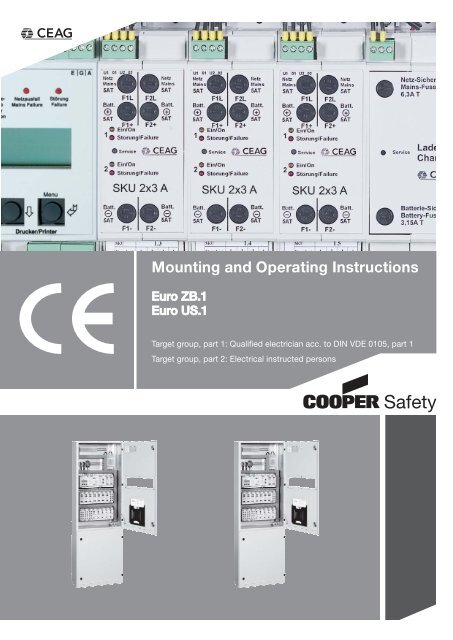
Mounting and Operating Manual<br />
Central <strong>Battery</strong> <strong>System</strong> <strong>EURO</strong> <strong>ZB.1</strong><br />
Table of contents<br />
Part 1<br />
1 Important Notes 4<br />
2 Product Description 5<br />
3 Technical Data 11<br />
4 Batteries for Emergency Power Supply 16<br />
4.1 Tending and Checking Batteries 17<br />
5 Modules Functioning 18<br />
5.1 Functions of Charging Unit LT.1 2,5 A 18<br />
5.2 Functions of DC/DC converter.2 19<br />
5.3 Functions of the ST 20 E Control Unit 20<br />
5.4 Function of Circuit Changeover SKU 2 x 3 A 21<br />
5.5 Function of Circuit Changeover SKU 1 x 6 A 22<br />
5.6 Function of Circuit Changeover SKU 4 x 1 A 23<br />
5.7 Circuit Changeover Units at a Glance 24<br />
5.8 Functions of Event Printer PD 2 25<br />
5.9 Print-out - Event Printer PD 2 26<br />
5.10 Function of the Relay Module (CG IV) 27<br />
5.11 Functions of the TLS Switching Module 28<br />
5.12 Function of the DLS Switching Module 29<br />
5.13 Functions of the SDS 8 Switching Module 30<br />
6 Block diagram 31<br />
6.1 Installation Example <strong>EURO</strong> <strong>ZB.1</strong> 32<br />
6.2 Installation Example <strong>EURO</strong> US.1 33<br />
7 Important Notes on Safety at Work and Safe Operation of the<br />
Emergency Lighting <strong>System</strong> <strong>EURO</strong> <strong>ZB.1</strong> 34<br />
8 Intended Use 35<br />
9 Transport, Storage and Disposal 36<br />
10 Mounting 37<br />
10.1 Mounting the Control Cabinet 38<br />
11 Installation of Emergency Lighting <strong>System</strong> 38<br />
11.1 Connection of the Mains Supply to <strong>EURO</strong> <strong>ZB.1</strong> 39<br />
11.2 Mains Connections to Substations <strong>EURO</strong> US.1 39<br />
11.3 Connecting the <strong>Battery</strong> Supply 40<br />
11.4 Connecting the <strong>Battery</strong> Supply of a <strong>EURO</strong> <strong>ZB.1</strong> Station 41<br />
11.5 Connecting the <strong>Battery</strong> Supply of a <strong>EURO</strong> US.1 Substation 41<br />
11.6 Connection of a Temperature Sensor 42<br />
11.7 Mounting and Connection of Internal Modules 42<br />
11.8 Connection of DLS Modules 43<br />
11.9 Connection of SDS 8 Modules 44<br />
11.10 Connection of TLS Modules 45<br />
11.11 Mounting and Connection of <strong>CEAG</strong> 3-phase Monitors with 24 V Loop 46<br />
11.12 Connection of a Remote Switch/F3 Module 47<br />
2 <strong>CEAG</strong> Notlichtsysteme GmbH
Mounting and Operating Manual<br />
Central <strong>Battery</strong> <strong>System</strong> <strong>EURO</strong> <strong>ZB.1</strong><br />
Table of contents<br />
12 Commissioning and Further Work 48<br />
12.1 Disconnecting/Switching-on an Emergency Lighting <strong>System</strong> under<br />
<strong>Battery</strong> Supply 49<br />
12.2 Disconnecting/Switching-on a <strong>EURO</strong> <strong>ZB.1</strong> or <strong>EURO</strong> US.1 control cabinet 49<br />
12.3 Block/Release the Control of a <strong>EURO</strong> <strong>ZB.1</strong><br />
or <strong>EURO</strong> US.1 control cabinet 49<br />
12.4 Checking all Connections / Insulation Testing 50<br />
12.5 Testing / Replacing Fuses 51<br />
12.6 Checking and Replacing Modules 52<br />
13 Switching the <strong>System</strong> ON 53<br />
Part 2<br />
14 Controlling a <strong>EURO</strong> <strong>ZB.1</strong> Central <strong>Battery</strong> <strong>System</strong> (<strong>EURO</strong> US.1) 54<br />
14.1 Control and Indicating Elements of the Modules 55<br />
15 Programming the ST 20 E Control Unit 57<br />
16 Programming the Charger Unit 58<br />
17 Monitoring of the Final Circuit 59<br />
18 Programming the Circuit Monitoring Function 60<br />
19 Programming the Final Circuit Switching Variants 61<br />
20 Programming Final Circuits to Switched Maintained Light 62<br />
21 Programming Final Circuits to Selective Em. Lighting Changeover (SDS 8) 63<br />
22 Programming Final Circuits to Staircase Lighting (TLS) 64<br />
23 Programming Staircase Lighting Cut-in Times 65<br />
24 Troubleshooting Overview Chart 66<br />
25 Starting Function Duration Test and Blocking the <strong>System</strong> 67<br />
26 Function Test Assessment 68<br />
27 Replacing Modules 69<br />
28 Cancel Fault Messages after Remedial Action 70<br />
29 VDE Requirements Governing Telecommunication Contacts and Buzzers 71<br />
30 Luminaire Position Plans 72-73<br />
31 Customer Service Requests 74<br />
32 Service Locations 75<br />
3 <strong>CEAG</strong> Notlichtsysteme GmbH
Mounting and Operating Manual<br />
Central <strong>Battery</strong> <strong>System</strong> <strong>EURO</strong> <strong>ZB.1</strong><br />
Important Notes<br />
1 Important Notes<br />
Mounting work must only be carried<br />
out by skilled electrical personnel (see<br />
IN VDE 0105 Part 1; the Accident Prevention<br />
Rules BGV A4 of the (German)<br />
Trade Workers’ Compensation Association<br />
(Hauptverband der gewerblichen<br />
Berufsgenossenschaften) or<br />
equivalent provisions and guidelines<br />
applicable in the country where the<br />
system is installed and operated).<br />
Other persons may perform the work<br />
described in this manual only if<br />
– they have been expertly instructed<br />
and trained,<br />
– their tasks and activities have been<br />
accurately defined and understood,<br />
– the work is carried out under the supervision<br />
of expert electrical personnel.<br />
When working with this manual the<br />
following notes provided with attention-attracting<br />
graphical symbols and<br />
identifiers (eg Note) shall be carefully<br />
observed:<br />
Note:<br />
indicates important hints and advice<br />
in connection with handling<br />
or manipulating the appliances or<br />
plant units described.<br />
Attention!<br />
draws attention to dangerous<br />
situations that may result in damage<br />
to plants or plant units as<br />
well as environmental hazards.<br />
Warning!<br />
draws attention to dangerous<br />
situations that may result in<br />
personal injuries or major<br />
damage to plants or plant units<br />
as well as major environmental<br />
damage.<br />
Danger!<br />
draws attention to dangerous<br />
situations that may result in lifethreatening<br />
personal injuries<br />
or most serious damage that<br />
consequentially may endanger<br />
persons or the environment.<br />
Moreover, when using this mounting<br />
and operating manual observe the<br />
following:<br />
Warning!<br />
The figures and elementary<br />
diagrams in this mounting and<br />
operating manual sometimes<br />
serve the sole purpose of providing<br />
elucidation on the subject<br />
matter described. Wherever<br />
– dimensionally true work is to<br />
be performed or<br />
– precise drawings or circuit<br />
diagrams tailored to local<br />
needs are required,<br />
the drawings and diagrams especially<br />
prepared for the lighting<br />
system must be strictly adhered<br />
to.<br />
Note:<br />
In the event a polyphase operation<br />
is not at all or only conditionally<br />
allowed, observance<br />
of the applicable national rules<br />
and regulations is to be viewed<br />
as a prerequisite in the sense of<br />
the Intended Use Paragraph (see<br />
«8 Intended Use»).<br />
Warning!<br />
Only perform work for which you<br />
are adequately qualified and specifically<br />
trained in the framework<br />
of local and operational needs!<br />
Work necessary for extensions,<br />
retrofits or repairs that has not<br />
been described in this manual<br />
must be carried out by specially<br />
trained expert service personnel<br />
(to be delegated by <strong>CEAG</strong><br />
as manufactgurer or sales and<br />
service companies authorized<br />
by <strong>CEAG</strong>)!<br />
Attention!<br />
When performing work on the<br />
unit ESD protection rules must<br />
be observed!<br />
Attention!<br />
If a reset occurs in battery mode<br />
the failure „battery disconnected“<br />
is shown after the restart.<br />
4 <strong>CEAG</strong> Notlichtsysteme GmbH
Mounting and Operating Manual<br />
Central <strong>Battery</strong> <strong>System</strong> <strong>EURO</strong> <strong>ZB.1</strong><br />
Product Description<br />
2 Product Description<br />
The central battery system serves for<br />
the battery-backed control and emergency<br />
supply of an emergency lighting<br />
system.<br />
The functions of the individual circuits<br />
are defined with the help of a userfriendly<br />
parameterization system.<br />
Three operating modes can be set:<br />
� Circuit monitoring<br />
Requirements: Electronic ballasts/<br />
modules meet all the requirements<br />
prescribed by EN 60924 and<br />
EN 60598-2-22).<br />
� Non-maintained mode<br />
� Maintained mode<br />
� Switched maintained mode<br />
These operating modes enable the<br />
emergency lighting system to be activated<br />
as follows:<br />
� Non-maintained mode: The emergency<br />
lighing is switched on<br />
– if the general lighting system fails<br />
due to the general power supply<br />
being interrupted,<br />
– when functional or operating duration<br />
testing has been activated<br />
manually or automatically.<br />
� Miantained mode: The emergency<br />
lights are always on.<br />
� Switched maintained mode : The<br />
emergency lighing is switched on<br />
– if the general lighting system fails<br />
due to the general power supply<br />
being interrupted,<br />
– when functional or operating duration<br />
testing has been activated<br />
manually or automatically,<br />
– as a result of switching checks (eg<br />
initiated by DLS modules).<br />
All settings are saved to a non-volatile<br />
memory so that they are not lost in<br />
case the entire power supply (230 V<br />
mains and battery backup) is down.<br />
Low-maintenance batteries are used<br />
to power the emergency lighting<br />
system in the event the normal 230 V<br />
power supply system is on failure.<br />
During normal operation the system<br />
monitors the batteries’ charging condition<br />
and, whenever needed, performs<br />
charging as necessary.<br />
The system has been designed and<br />
manufactured in conformity with the<br />
following EU guidelines:<br />
� Low-voltage guideline 73/23/EWG as<br />
amended by guideline 93/68/EWG<br />
� Guideline 89/336/EWG on electromagnetic<br />
compatibility<br />
Details of national (DIN), European<br />
(EN) and international (IEC) standards<br />
complied with are included in the unit’s<br />
CE Statement of Compliance.<br />
Warning!<br />
Since the central battery system<br />
is an important component within<br />
a facility’s security system, any<br />
planning, commissioning and parameterization<br />
activities have to<br />
be performed by experts perfectly<br />
familiar with the related safety<br />
equipment and systems.<br />
5 <strong>CEAG</strong> Notlichtsysteme GmbH
Fig. 1: <strong>EURO</strong> <strong>ZB.1</strong> of type <strong>EURO</strong><br />
<strong>ZB.1</strong>/200S and for operation with a<br />
battery capacity of up to 240 Ah and<br />
up to 26 SKU modules<br />
Fig. 2: <strong>EURO</strong> <strong>ZB.1</strong> of type ZB 96/ LAD<br />
for operation with battery capacities<br />
of up to 240 Ah and up to 10 charging<br />
boosters 2.5 A.<br />
This unit is capable of powering up to<br />
15 type <strong>EURO</strong> US.1 substations with<br />
230 V mains and battery power.<br />
Mounting and Operating Manual<br />
Central <strong>Battery</strong> <strong>System</strong> <strong>EURO</strong> <strong>ZB.1</strong><br />
Product Description<br />
To suit local conditions a number of different<br />
system configurations are employed.<br />
These standardized configurations are<br />
identified, for example, as follows:<br />
� <strong>EURO</strong> <strong>ZB.1</strong>/52<br />
To operate max. 26 circuit modules type<br />
SKU. Up to 6 substations <strong>EURO</strong> US.1<br />
can be supplied with battery and mains<br />
power (up to 6 substations, singlephase).<br />
� ZB 96/LAD<br />
These are designed as charging and<br />
monitoring units for the mains and<br />
battery power supply of a greater number<br />
of substations type <strong>EURO</strong> US.1. Up to<br />
two SKU modules can be energized and<br />
controlled.<br />
� <strong>EURO</strong> <strong>ZB.1</strong>/20K, <strong>EURO</strong> <strong>ZB.1</strong>/188K<br />
Designed (as regards dimensions) to<br />
be operated in conjunction with <strong>CEAG</strong><br />
compact battery cabinets (max. 10 or 18<br />
SKU modules).<br />
� <strong>EURO</strong> US.1/72 oder <strong>EURO</strong> US.1/26<br />
Designed as substations for operation<br />
with max. 36, 13 etc. circuit modules<br />
types SKU to perform only control and<br />
monitoring tasks for subsystems of the<br />
lighting equipment.<br />
These substations do not provide for<br />
charging means for the connected battery<br />
emergency supply ; the battery and<br />
mains power supply is effected via the<br />
<strong>EURO</strong> <strong>ZB.1</strong> system.<br />
What is included in this manual also<br />
applies analogously to the <strong>EURO</strong> US.1<br />
configurations listed under «3 Technical<br />
Data».<br />
For emergency power supply <strong>CEAG</strong><br />
battery cabinets or racks are employed.<br />
The storage capacity of the battery<br />
banks to be connected (battery cabinets<br />
or racks) is governed, inter alia, by the<br />
available charging capacity (see configurations<br />
listed under«3 Technical Data»).<br />
Notes:<br />
� Planning and design information<br />
can be seen from the <strong>CEAG</strong> catalog<br />
„Safety Luminaires and Safety Lighting<br />
<strong>System</strong>s“ as amended under<br />
catchwords / chapters such as:<br />
– Equipment Overview / Technical<br />
Data<br />
– Planning<br />
– Equipment Possibilities<br />
– Inquiry Texts<br />
� Under the heading «Components<br />
and Options» brief charactericts,<br />
technical data and ordering<br />
numbers for modules and supplements<br />
can be found that may<br />
be operated via a <strong>EURO</strong> <strong>ZB.1</strong> or<br />
<strong>EURO</strong> US.1 system.<br />
� Moreover, <strong>CEAG</strong> offers consultation<br />
and training services for<br />
planning, set-up and operation of<br />
lighting systems comprising the<br />
<strong>EURO</strong> <strong>ZB.1</strong> system.<br />
� For relevant information please<br />
visit our website www.ceag.de.<br />
A <strong>EURO</strong> <strong>ZB.1</strong> system supplies and monitors<br />
lighting /emergency lighting circuits<br />
comprising luminaires and electronic<br />
ballasts included in the <strong>CEAG</strong> Safety Luminaires<br />
Program. For emergency power<br />
supply battery cabinets from the CEAL<br />
supply program can be used having a<br />
storage capacity of up to 240 Ah (see<br />
standard cabinet types under „3 Technical<br />
Data“).<br />
6 <strong>CEAG</strong> Notlichtsysteme GmbH
Mounting and Operating Manual<br />
Central <strong>Battery</strong> <strong>System</strong> <strong>EURO</strong> <strong>ZB.1</strong><br />
Product Description<br />
The following supplementary functions<br />
can be realized:<br />
� Connecting <strong>CEAG</strong> 3-phase detectors<br />
(3PhW) to monitor the general supply<br />
system or its subdistribution boards.<br />
This enables a mains-to-emergency<br />
power switchover in case a phase of<br />
the general mains supply for general<br />
lighting purposes fails.<br />
– When using conventional <strong>CEAG</strong><br />
3-phase detectors in distribution<br />
boards signallingis effected via a<br />
24-V current loop (connections S3<br />
/ S4 on the ST 20 E control unit).<br />
Depending on its settings the ST 20 E<br />
control unit will then control the emergency<br />
lighting circuits and signals<br />
are transmitted to a higher-ranking<br />
annunciator (F3 module or CG controller)<br />
or to a building automation<br />
system or the E/G/A bus.<br />
� Monitoring the switching state of<br />
switches to enable local control of<br />
the general lighting system via DLS or<br />
SDS 8 modules. (see circuit diagrams<br />
under „11.7 Mounting and connection<br />
of Internal Modules“ et sqq.).<br />
Messages indicating the current switching<br />
states are sent via the internal<br />
bus to the ST 20 E control unit.<br />
Depending on its settings the control<br />
unit will then switch the relevant<br />
circuits „ON“ or „OFF“.<br />
� Monitoring the switching states of<br />
staircase buttons for general lighting<br />
purposes by means of TLS modules.<br />
Similar to the above mentioned DLS<br />
modules the current switching states<br />
are transmitted to enable the respective<br />
emergency lighting circuits to be<br />
controlled.<br />
� Floating signalling contacts of the ST<br />
20 E control unit:<br />
Via 3 signalling relay contacts on the<br />
ST 20 E control unit the system’s<br />
operating state can be detected and<br />
indicated for example via the LEDs of<br />
a <strong>CEAG</strong> F3 remote indication unit.<br />
The maximum load rating of the connections<br />
for these signalling contacts<br />
is 24 V AC/DC and 0.5 A; the maximum<br />
line length is 1000 m.<br />
� Functional monitoring via a higherranking<br />
supervision system.<br />
For this purpose <strong>CEAG</strong> emergency<br />
lighting systems offer a CG controller<br />
or the CG Vision supervisory system.<br />
Further information in this context can<br />
be taken from the <strong>CEAG</strong> catalog or<br />
respective operating manuals.<br />
� Connection of a <strong>CEAG</strong> F3 remote<br />
indicator unit (with key-operated<br />
switch).<br />
This device combines a status<br />
indication via the signalling contacts<br />
of the ST 20 E control unit and a keyoperated<br />
switch to deactivate/block<br />
the emergency lighting system.<br />
Messages indicated:<br />
– <strong>System</strong> operative<br />
– <strong>Battery</strong> operation<br />
– <strong>System</strong> on failure<br />
This F3 remote indicating unit may<br />
have a line length of up to 1000 m.<br />
The maximum cross sectional area is<br />
2.5 mm².<br />
Note:<br />
In the Federal Republic of Germany<br />
a remote indicating system must be<br />
mounted in permanently attended<br />
place as prescribed by DIN VDE<br />
0108. Make sure to observe any<br />
national regulations ruling in the<br />
country where the lighting system<br />
is to be operated.<br />
7 <strong>CEAG</strong> Notlichtsysteme GmbH
Mounting and Operating Manual<br />
Central <strong>Battery</strong> <strong>System</strong> <strong>EURO</strong> <strong>ZB.1</strong><br />
Product Description<br />
Fig. 3: Example of a control cabinet layout (<strong>EURO</strong> <strong>ZB.1</strong>/52)<br />
7<br />
5<br />
6<br />
6<br />
8<br />
a<br />
b<br />
c<br />
9<br />
a<br />
b<br />
1 2 3 4<br />
1: Control cabinet including:<br />
2: Top cover with prepunched cable glands for M type glands (eg. for end circuit<br />
leads and/or the supply of <strong>EURO</strong> US.1 substations)<br />
3: Control cabinet with mounted components (examples - right-hand door hinge)<br />
4: Control unit, DLS, SDS 8 or TLS modules as well as charger (battery monitoring<br />
and charging control) and 2 slots for LON module and CGIV module l<br />
5: DC/DC converter (for internal power supply to electronic compontents) and<br />
SKU-modules<br />
6: 2 x 8 slots SKU 2 x 3 A, SKU 1 x 6 A or SKU 4 x 1 A<br />
7: Terminal block for connection of emergency lighting circuit protective conductor<br />
8: (a) Load-break switch/lv hrc fuses (mains), (b) outgoing distributor/mains<br />
optional for up to 6 <strong>EURO</strong> US.1 substations (1-phase) and (c) distributor<br />
(mains) for the <strong>EURO</strong> <strong>ZB.1</strong> control cabinet<br />
9: Terminals for (a) N and (b) PE for mains supply and distribution<br />
10: (a) Load-break switch/lv hrc fuses (batteries), (b) outgoing distributor (batteries)<br />
optional for up to 6 <strong>EURO</strong> US.1 substations and (c) distributor (batteries)<br />
for the <strong>EURO</strong> <strong>ZB.1</strong> control cabinet<br />
11: (a) Mounting rack with (b) 4 charging boosters 2.5 A (further booster units<br />
optional)<br />
8 <strong>CEAG</strong> Notlichtsysteme GmbH<br />
10<br />
a)<br />
b)<br />
c)<br />
11<br />
a<br />
b
1: Control unit <strong>EURO</strong> <strong>ZB.1</strong><br />
2: Pluggable screw terminal blocks,<br />
removable for installation/removal of<br />
modules, used for all cabinet assemblies<br />
1 )<br />
Mounting and Operating Manual<br />
Central <strong>Battery</strong> <strong>System</strong> <strong>EURO</strong> <strong>ZB.1</strong><br />
Product Description<br />
Fig. 4: Detail view of control unit, DC/DC converter, charging unit and SKU circuit changeover<br />
3: Power changeover modules SKU<br />
for circuit changeover, two modules<br />
of type SKU 2 x 3 A are shown 1 )<br />
4: Charging unit LT.1 2.5 A 3 ) for charging<br />
and monitoring pertinent battery<br />
banks<br />
1 ) External incoming and outgoing lines are connected to the modules. The protective conductor is connected to terminal strip<br />
X12<br />
2 ) For further details and technical description consult current issue of <strong>CEAG</strong> catalog „Safety Luminaires and Safety Lighting<br />
<strong>System</strong>s“.<br />
3 ) In case of higher battery capacity additional charging boosters are needed (see Fig.3, Item 12). Booster controls is effected via<br />
charging unit LT.1 2.5 A (see Item 4 above).<br />
<strong>EURO</strong> <strong>ZB.1</strong> system components:<br />
Control unit ST 20 E<br />
1 2 3<br />
4<br />
Circuit changeover modules<br />
SKU 2 x 3 A<br />
DLS, SDS 8 module<br />
and TLS, LON<br />
and CGIV module<br />
DC/DC converter.2 Charging unit LT.1 2,5 A Event printer PD 2<br />
9 <strong>CEAG</strong> Notlichtsysteme GmbH
Mounting and Operating Manual<br />
Central <strong>Battery</strong> <strong>System</strong> <strong>EURO</strong> <strong>ZB.1</strong><br />
Product Description<br />
Fig. 8: Detail view of control unit ST 20 E (terminal blocks on module serve to facilitate mounting and removal ov the<br />
module.<br />
1 2 4 9<br />
1: Control unit housing<br />
5<br />
8<br />
3<br />
2: Safety screw for the plug-type control<br />
unit module<br />
3: 24V query contacts for blocking the<br />
system via remote switches (S1/S2)<br />
and emergency light request (S3/S4),<br />
eg. through a (conventional) <strong>CEAG</strong><br />
3-phase detector.<br />
4: Floating signalling relay contacts<br />
1 ... 3, with contact assignment NC<br />
open (11/12), NO open (21/22) and<br />
(31/32)<br />
5: Contact identification for the signalling<br />
relay contacts (see Item 5), eg. for<br />
remote indication (mains operation /<br />
battery operation / fault) or freely configurable<br />
signalling behavior (default<br />
settings as per DIN VDE 108 available)<br />
as needed for higher-ranking<br />
building automation purposes.<br />
6: LC backlit display (4 lines, 20 characters<br />
each)<br />
7: Menu button<br />
The „menu“ button serves for central<br />
battery system programming. Pressing<br />
the button causes menu items to<br />
be shown on the display which can<br />
be selected via the<br />
„UP (�)“ and „DOWN (�)“ buttons.<br />
8: „UP (�)“, „DOWN (�)“ buttons<br />
These buttons serve programming or<br />
status inquiry selection purposes.<br />
9: E/G/A bus connections<br />
Up to 256 devices can be centrally<br />
connected to the monitoring/supervision<br />
system (CG Vision) via these<br />
terminals.<br />
10: LEDs for operating status indication<br />
Green LED - Operation -<br />
is illuminated when the unit is operative.<br />
Yellow LED - <strong>Battery</strong> operation - is<br />
illuminated if the battery powers the<br />
safety lighting system.<br />
Red LED - Mains failure -<br />
is illuminated if the external phase<br />
detectors signal mains failure via the<br />
24-V monitoring loop or in case the<br />
mains supplying the <strong>EURO</strong> <strong>ZB.1</strong> is<br />
down.<br />
Red LED - Fault -<br />
is illumianted if a centralized alarm/<br />
fault exists. The cause of the fault is<br />
shown on the display.<br />
10 <strong>CEAG</strong> Notlichtsysteme GmbH<br />
10<br />
6<br />
7
Fig. 9: Inside view of <strong>EURO</strong> <strong>ZB.1</strong>/52<br />
Fig.10: Cable entries are prepunched<br />
(here <strong>EURO</strong> <strong>ZB.1</strong>/52, other types,<br />
eg. sponge rubber, are available on<br />
request)<br />
1 = M40/M32<br />
2 = M32<br />
3 = M16<br />
4 = M20/M25<br />
Mounting and Operating Manual<br />
Central <strong>Battery</strong> <strong>System</strong> <strong>EURO</strong> <strong>ZB.1</strong><br />
Technical Data<br />
3 Technical Data<br />
<strong>EURO</strong> <strong>ZB.1</strong> Control Cabinet <strong>EURO</strong> <strong>ZB.1</strong>/52 ZB 96/LAD<br />
Rated operating voltage: ----------- 400/230 V 50 Hz -------------<br />
Control unit <strong>EURO</strong> <strong>ZB.1</strong> 1 1<br />
DC/DC converter.2 1 1<br />
Charging unit LT.1 2,5 A 1 1<br />
Circuit module SKU 0 - 26 0 - 2 1 )<br />
Charging booster 2.5 A 0 - 6 2 ) 0 - 10 1 )<br />
Outgoing distributor,<br />
1-phase outgoing circuits (optional) 0 - 6 3 ) 0 - 15<br />
Dimensions (mm) W 800 800<br />
H 2050 2050<br />
D 400 400<br />
plus optional base (mm) H 100/200 100/200<br />
Weight (depends on components mounted) upon request<br />
Adm. system temperature ranges: storage -20 °C to + 40 °C<br />
operation -5 °C to + 35 °C<br />
Batteries: Nominal temperature + 20 °C 5)<br />
Enclosure type as per DIN EN 60 529 IP 21 IP 21<br />
Prot. class as per DIN EN 60 598 I I<br />
3-phase system division Wiring block Wiring block<br />
Cable entry at top/bottom possible yes / yes yes / yes<br />
Conductor size 4 )<br />
<strong>Battery</strong> and mains lead up to 50 mm 2 50 mm 2 50 mm 2<br />
Outgoing distributor up to 16 mm 2 16 mm 2 16 mm 2<br />
Final circuits up to 2,5 mm 2 2,5 mm 2 2,5 mm 2<br />
Control unit <strong>EURO</strong> <strong>ZB.1</strong> up to 2.5 mm 2 conductor size<br />
<strong>Battery</strong> power supply via <strong>CEAG</strong> standard<br />
battery cabinet 1-fold 23.3 - 89.4 Ah 6)<br />
(W x D x H, in mm) 800 x 400 x 2050 2-fold 6) 5)<br />
118 - 178.8 Ah<br />
1 ) when mounting 2 SKUs only a max.of 8 charging boosters can be used<br />
2 ) when mounting 6 charging boosters an additional booster carrier, 2-fold, must be arranged<br />
3 ) for 1-phase operation (for 3-phase operation 0-2 outgoing circuits)<br />
4 ) Conductor sizes of the connecting leads must be selected to suit the type of mains power<br />
supply and requirements of the consumer circuits in line with the applicable regulations and<br />
standards (ruling at the operating location of the plant)<br />
5 ) The optimum operating temperature is +20 °C. Lower temperatures will impair the available<br />
capacity. Higher temperatures will reduce the usability period.<br />
The technical data apply to a nominal temperature of +20 °C.<br />
6 ) The battery capacity may be raised to 354 Ah by a connection in parallel.<br />
1 3<br />
2 3<br />
11 <strong>CEAG</strong> Notlichtsysteme GmbH<br />
4<br />
4
Fig. 9a: Inside view of<br />
<strong>EURO</strong> <strong>ZB.1</strong>/188K<br />
Mounting and Operating Manual<br />
Central <strong>Battery</strong> <strong>System</strong> <strong>EURO</strong> <strong>ZB.1</strong><br />
Technical Data<br />
Compact Control Cabinet <strong>EURO</strong> <strong>ZB.1</strong>/20K /26K /188K /18K<br />
Rated operating voltage: --------------- 230 V 50 Hz ----------------<br />
Control unit <strong>EURO</strong> <strong>ZB.1</strong> 1 1 1 1<br />
DC/DC converter.2 1 1 1 1<br />
Charging unit 2.5 A 1 1 1 1<br />
Circuit module SKU 0 - 10 0 - 10 0 - 18 0 - 10<br />
Charging booster 2.5 A 0 - 1 7 ) 0 - 2 8 ) none none<br />
Outgoing distributor, 1-phase,<br />
Outgoing circuits 2 2 7 ) 1 1<br />
Dimensions (mm) W 800 800 600 600<br />
H 2050 2050 1800 1800<br />
D 400 600 350 350<br />
plus optional base (mm) H 200 – 200 200<br />
Weight (depends on outfit) upon request<br />
Adm. system temperature ranges: storage -20 °C to + 40 °C dtto.<br />
operation -5 °C to + 35 °C dtto.<br />
Batteries: Nominal temperature + 20 °C 5)<br />
Enclosure type (DIN EN 60 529) IP 21 IP 21 IP 21 IP21<br />
Prot. class as per DIN EN 60 598 I I I I<br />
3-phase system division no no no no<br />
Cable entry<br />
at top/bottom possible yes / no yes / no yes / no yes/no<br />
Conductor size 4 )<br />
<strong>Battery</strong> and mains leads up to 16 mm 2 16 mm 2 16 mm 2 16 mm 2<br />
Outgoing distributor up to 35 mm 2 35 mm 2 16 mm 2 16 mm 2<br />
Final circuits up to 2.5 mm 2<br />
Control unit ST20 up to 2.5 mm 2 conductor size<br />
<strong>Battery</strong> power supply via <strong>CEAG</strong><br />
compact battery cabinet (Ah) 5.5 - 49.5 5.5 - 89.4 5.5 - 23.3 5.5-23.3<br />
(W x D x H in mm) see applicable mounting and operating manual<br />
7 ) When mounting up to 1 charging booster a 1-fold charging booster adapter must<br />
be provided.<br />
8 ) When mounting up to 2 charging booster a 2-fold charging booster adapter must<br />
be provided.<br />
Attention!<br />
When planning the equipment and during subsequent operation make<br />
sure that<br />
� the systems are sufficiently cooled (compare remarks under „Adm.<br />
temperature ranges“),<br />
� environmental requirements are met as per type of enclosure and protection<br />
class (regarding protection against contact with live components<br />
and ingress of dust, foreign materials or moisture),<br />
� the line length of an emergency lighting circuit up to the last luminaire<br />
of the circuit does not exceed the admissible line length.<br />
12 <strong>CEAG</strong> Notlichtsysteme GmbH
Fig. 9a: Inside view of<br />
<strong>EURO</strong> <strong>ZB.1</strong>/204K<br />
Fig.10: Cable entries are prepunched<br />
(here <strong>EURO</strong> <strong>ZB.1</strong>/52, other types,<br />
eg. sponge rubber, are available on<br />
request)<br />
1 = M40/M32<br />
2 = M32<br />
3 = M16<br />
4 = M20/M25<br />
Mounting and Operating Manual<br />
Central <strong>Battery</strong> <strong>System</strong> <strong>EURO</strong> <strong>ZB.1</strong><br />
Technical Data<br />
Compact Control Cabinet <strong>EURO</strong> <strong>ZB.1</strong>/204K /264K<br />
Rated operating voltage: --------------- 230 V 50/60 Hz---------------<br />
Control unit <strong>EURO</strong> <strong>ZB.1</strong> 1 1<br />
DC/DC converter.2 1 1<br />
Charging unit LT.1 2.5 A 1 1<br />
Circuit module SKU 0 - 14 0 - 14<br />
Charging booster 2.5 A 0 - 1 7 ) 0 - 2 8 )<br />
Outgoing distributor, 1-phase,<br />
Outgoing circuits - -<br />
Dimensions (mm) W 800 800<br />
H 2050 2050<br />
D 400 600<br />
plus optional base (mm) H 200 –<br />
Weight (depends on components<br />
mounted) upon request<br />
Adm. system temperature range: storage -20 °C to + 40 °C<br />
operation -5 °C to + 35 °C<br />
Batteries: Nominal temperature + 20 °C 5)<br />
Enclosure type as per DIN EN 60 529 IP 21 IP 21<br />
Prot. class as per DIN EN 60 598 I I<br />
3-phase system division no no<br />
Cable entry<br />
at top/bottom possible yes / no yes / no<br />
Conductor size 4 )<br />
<strong>Battery</strong> and mains leads up to 16 mm 2 16 mm 2<br />
Outgoing distributor up to - -<br />
Final circuits up to 2.5 mm 2 2.5 mm 2<br />
Control unit ST 20 E up to 2.5 mm 2 conductor size<br />
<strong>Battery</strong> power supply via <strong>CEAG</strong><br />
compact battery cabinet (Ah) 5.5 - 49.5 5.5 - 89.4<br />
(W x D x H in mm) see pertinent mounting and operating manual<br />
7 ) When mounting up to 1 charging booster a 1-fold charging booster adapter must<br />
be provided.<br />
8 ) When mounting up to 2 charging booster a 2-fold charging booster adapter must<br />
be provided.<br />
1 3<br />
2 3<br />
13 <strong>CEAG</strong> Notlichtsysteme GmbH<br />
4<br />
4
Fig.11: Inside view of <strong>EURO</strong> US.1/72<br />
Fig.12: Cable entries are prepunched<br />
(other types, eg. sponge rubber, are<br />
available on request)<br />
1 = M40/M32<br />
2 = M32<br />
3 = M16<br />
4 = M20/M25<br />
Mounting and Operating Manual<br />
Central <strong>Battery</strong> <strong>System</strong> <strong>EURO</strong> <strong>ZB.1</strong><br />
Technical Data<br />
Substation <strong>EURO</strong> US.1 <strong>EURO</strong> US.1/72 <strong>EURO</strong> US.1/42<br />
Rated operating voltage: ----------- 230 V 50/60 Hz -------------<br />
Control unit ST 20 E 1 1<br />
DC/DC converter (model DC/DC.2) 1 - 2 1<br />
Charging unit LT.1 2.5 A none none<br />
Circuit module SKU 0 - 36 1 ) 0 - 21<br />
Charging booster 2.5 A none none<br />
Outgoing distributor/ circuits (optional) none none<br />
Dimensions (mm) W 800 600<br />
H 2050 1200<br />
D 400 300<br />
plus optional base (mm) H 100 / 200 300<br />
Weight (depends on components mounted) upon request<br />
Adm. system temperature ranges: storage -20 °C to + 40 °C<br />
operation -5 °C bis + 35 °C<br />
Batteries: --------------------------------------------<br />
Enclosure type as per DIN EN 60 529 IP 21 IP 54<br />
Prot. class as per DIN EN 60 598 1 1<br />
3-phase system division no no<br />
Cable entry<br />
at top/bottom possible yes / yes yes / no<br />
Conductor size 2 )<br />
<strong>Battery</strong> and mains lead up to 35 mm 2 35 mm 2<br />
Outgoing distributor up to – –<br />
Final circuits up to 2,5 mm 2 2,5 mm 2<br />
Control unit ST 20 E up to 2.5 mm 2 conductor size<br />
<strong>Battery</strong> and mains power supply via outgoing distributor in a<br />
<strong>EURO</strong> <strong>ZB.1</strong> control cabinet<br />
1 ) One DC/DC.2 converter can supply operating voltage to a max. of 26 modules;<br />
for more than 26 modules an additional DC/DC.2 converter must be installed.<br />
2 ) Conductor sizes of the connecting leads must be selected to suit the type of<br />
mains power supply and requirements of the consumer circuits in line with the<br />
applicable regulations and standards (ruling at the operating location of the plant).<br />
1 3<br />
2 3<br />
4<br />
4<br />
14 <strong>CEAG</strong> Notlichtsysteme GmbH
Mounting and Operating Manual<br />
Central <strong>Battery</strong> <strong>System</strong> <strong>EURO</strong> <strong>ZB.1</strong><br />
Technical Data<br />
Substation <strong>EURO</strong> US.1 <strong>EURO</strong> US.1/26 /10 /ESF-E30/17 9 ESF-E30/28 9<br />
Rated operating voltage: -------------------------- 230 V 50/60 Hz ------------------------<br />
Control unit ST 20 E 1 1 1 1<br />
DC/DC converter (model DC/DC.2) 1 1 1 1<br />
Charging unit LT.1 2.5 A none none none none<br />
Circuit module SKU 0 - 13 0 - 5 0 - 17 0 - 26<br />
Charging booster 2.5 A none none none none<br />
Outgoing distributor/ circuits none none none none<br />
Dimensions (mm) W 600 400 885 885<br />
H 800 600 1150 2190<br />
D 250 250 405 405<br />
plus optional base (mm) H – – – –<br />
Weight (depending on components mounted) upon request<br />
Adm. system temperature range: storage -20 °C to + 40 °C<br />
operation -5 °C to + 35 °C<br />
Batteries: -----------------------------------------------------------------------------<br />
Enclosure type as per DIN EN 60 529 IP 54 IP 54 IP 54 IP 54<br />
Protection class as per DIN EN 60 598 1 1 1 1<br />
3-phase system division no no no no<br />
Cable entry<br />
at top/bottom possible yes / no yes / no yes / no yes / no<br />
Conductor size 2 )<br />
<strong>Battery</strong> and mains lead up to 35 mm 2 16 mm 2 16 mm 2 16 mm²<br />
Outgoing distributor up to – – – –<br />
Final circuits up to 2,5 mm 2 2,5 mm 2 4,0 mm² 4,0 mm²<br />
Control unit ST 20 E up to 2.5 mm 2 conductor size up to 4,0 mm² conductor size<br />
<strong>Battery</strong> and mains power supply via outgoing distributors in a <strong>EURO</strong> <strong>ZB.1</strong> control cabinet<br />
The technical data apply to a nominal temperature of +20 °C.<br />
2 ) Conductor sizes of the connecting leads must be selected to suit the type of mains power supply and requirements of the<br />
consumer circuits in line with the applicable regulations and standards (ruling at the operating location of the plant).<br />
4 ) E30 means fire protection class 30 prescribing functions to be maintained for at least 30 minutes (verified by a state-certified<br />
materials testing institute of the Federal Republic of Germany based on DIN 4102 part 2 and part 12).<br />
Attention!<br />
When planning the equipment and during subsequent operation make sure that<br />
� the systems are sufficiently cooled (compare remarks under „Adm. temperature ranges“),<br />
� environmental requirements are met as per type of enclosure and protection class (regarding protection against<br />
contact with live components and ingress of dust, foreign materials or moisture),<br />
� the line length of a lighting circuit up to the last luminaire of the circuit does not exceed the admissible line<br />
length.<br />
15 <strong>CEAG</strong> Notlichtsysteme GmbH
Mounting and Operating Manual<br />
Central <strong>Battery</strong> <strong>System</strong> <strong>EURO</strong> <strong>ZB.1</strong><br />
Batteries<br />
4 Batteries for Emergency Power Supply<br />
<strong>CEAG</strong> offers battery cabinets of various sizes and accommodating various components.<br />
Low-maintenance batteries according to <strong>EURO</strong>BAT standard are provided<br />
the service life of 10 years if handled and operated properly and with circumspection.<br />
Regarding design and type these <strong>CEAG</strong> approved batteries meet all<br />
the requirements applicable in the Federal Republic of Germany to safety lighting<br />
systems prescribed by building laws (EN 50272 and EN 60896-2). In this context<br />
our operating instructions for battery cabinets 300 80 001 441 and for battery racks<br />
300 80 001 442 must also be observed.<br />
<strong>CEAG</strong> standard battery cabinets<br />
Capacity range 23.3 to 354 Ah 1 )<br />
Rated voltage 216 V DC<br />
Dimensions (depends on type) vary 2 )<br />
Weight (depends on type) varies 2 )<br />
<strong>CEAG</strong> compact battery cabinets<br />
Capacity range 5.5 to 89.4 Ah<br />
Rated voltage 216 V DC<br />
Dimensions (depends on type) vary 2 )<br />
Weight (depends on type) varies 2 )<br />
<strong>CEAG</strong>-Batteriegestelle<br />
Capacity range 23.3 to 354 Ah 1 )<br />
Rated voltage 216 V DC<br />
Dimensions (depends on type) vary 3 )<br />
Weight (depends on type) varies 3 )<br />
<strong>Battery</strong> operating temperature<br />
The optimum operating temperature is +20 °C. Niedrigere Lower temperatures will<br />
impair the available capacity. Higher temperatures will reduce the usability period.<br />
The technical data apply to a nominal temperature of +20 °C. In this context our<br />
operating instructions for battery cabinets 300 80 001 441 and for battery racks<br />
300 80 001 442 must also be observed.<br />
1 ) By connecting several battery sets in parallel battery capacities exceeding 118 Ah<br />
can be obtained.<br />
2 ) See <strong>CEAG</strong> Installation Instructions for battery cabinets (300 80 001 441)<br />
3 ) See <strong>CEAG</strong> Installation Instructions for battery racks (300 80 001 442)<br />
16 <strong>CEAG</strong> Notlichtsysteme GmbH
Fig. 14: Charging characteristic<br />
Mounting and Operating Manual<br />
Central <strong>Battery</strong> <strong>System</strong> <strong>EURO</strong> <strong>ZB.1</strong><br />
Batteries<br />
4.1 Tending and Checking Batteries<br />
Inspection<br />
The following minimum inspection instructions must be observed to ensure the full<br />
service life of the batteries. In case of records being incomplete and/or failure to<br />
carry out battery inspections the warranty may become void or legally ineffective.<br />
The following shall be measured and recorded at least every 6 months:<br />
1. Voltage of individual battery blocks with charger being switched off.<br />
2. Floating operation voltage of the individual battery blocks.<br />
3. Floating operation voltage of the battery system.<br />
Annual checks:<br />
1. Semi-annual inspections must be repeated.<br />
2. All connections must be checked for cleanliness, continuity and resistance.<br />
3. All connections must be retightened as recommended using a torque wrench.<br />
4. Checking the set-up and accommodation of the batteries.<br />
5. Checking ventilation effectiveness.<br />
6. The batteries must be discharged and their condition inspected as prescribed<br />
by VDE 0108.<br />
Please only use leak proof batteries!<br />
<strong>Battery</strong> charging<br />
The low-maintenance batteries offered by <strong>CEAG</strong> are properly charged to suit temperature<br />
requirements and according to the adjacent I/U charging characteristics.<br />
To suit the respective battery charging condition high-rate charging (via boosters)<br />
is carried out so that the batteries are quickly charged without the gassing voltage<br />
being exceeded.<br />
The patented charging supervision process serves to permanently check the charging<br />
operation and immediately report faults such as battery circuit interruption,<br />
defect charger unit or high-resistance cells.<br />
Note: When battery is taken into operation make sure that the float charge voltage<br />
is according to manufacturers information.<br />
Remarks: No gas will escape under normal charging conditions. Distilled water<br />
for make-up purposes cannot be filled in since the batteries are permanently<br />
sealed. Higher temperatures will shorten the battery service life<br />
(cf. „<strong>Battery</strong> operating temperature“ on the preceding page).<br />
Attention!<br />
� Batteries for emergency operation must only be stored for a period<br />
not exceeding three months without being charged!<br />
� If the mains power to the <strong>EURO</strong> <strong>ZB.1</strong> central battery system is interrupted<br />
for more than three days the battery circuits must be<br />
disconnected (remove battery fuse). This work must exclusively be<br />
performed by skilled electrical personnel (cf. „12.5 Testing / Replacing<br />
Fuses“).<br />
17 <strong>CEAG</strong> Notlichtsysteme GmbH
Mounting and Operating Manual<br />
Central <strong>Battery</strong> <strong>System</strong> <strong>EURO</strong> <strong>ZB.1</strong><br />
Modules<br />
5 Modules Functioning<br />
5.1 Functions of Charging Unit LT.1 2.5 A<br />
Control elements<br />
Charging unit LT.1 2.5 A has the following<br />
control elements:<br />
� End-of-charge voltage<br />
The final charging voltage and charging<br />
current are set in the Factory using two<br />
potentiometers on the faceplate.<br />
� Service button<br />
Behind the bore identified „Service“<br />
there is a button which must be actuated<br />
for basic programming of the system.<br />
Basic programming is carried out in the<br />
Factory.<br />
� ISO monitor button<br />
As per VDE 0108 Part 1 a testing device<br />
must be provided by means of which the<br />
line isolation monitor functioning can be<br />
verified:<br />
Upper button pressed = Iso failure batt. +<br />
Lower button pressed = Iso failure batt. -<br />
Indicating elements<br />
� „On“ LED<br />
The LED is on if the charger is in operation.<br />
Failure of the LED to light up means<br />
- the charger is on failure or<br />
- mains voltage is interrupted or<br />
- function testing has been initiated.<br />
� „Boost charge“ LED<br />
The „Boost charge“ LED lights up during<br />
high-rate charging, eg. after a mains<br />
failure or operating duration testing.<br />
� „Charge fault“ LED<br />
The „Charge failure“ LED lights up if the<br />
charger, the charging boosters, or batteries<br />
are on failure. Further fault messages<br />
can be seen via the control unit.<br />
� „<strong>Battery</strong> capacity“ LED<br />
The LEDs show the remaining capacity in<br />
percent. As long as the battery capacity<br />
has no defined value (battery full, flat) or<br />
a „<strong>Battery</strong> interruption“ failure is encountered<br />
the „> 10 %“ LED flashes.<br />
Fuse protection<br />
Two fuses are provided on the faceplate<br />
of the charging unit:<br />
� On mains fuse 6.3 AT<br />
� On charging fuse 3.15 AT<br />
Connection terminals<br />
The terminals are of push-lock type.<br />
Note:<br />
To facilitate installation the terminals<br />
may be removed.<br />
� Floating signaling contacts<br />
Potential-free signals can be transmitted<br />
via terminals „11-12“, „21-22“, „31-32“.<br />
Contact „11/12“ is closed in case of<br />
failures.<br />
Contact „21/22“ is closed in case of an<br />
isolation failure.<br />
Contact „31/32“ is closed in case of<br />
high-rate charging.<br />
� Temperature sensor<br />
An external temperature sensor is to be<br />
connected to terminals „F+“ and „F-“.<br />
A shielded 2-wire lead must be used for<br />
temperature sensor connection. Due to<br />
the measuring current being very small a<br />
conductor size of 0.5 mm 2 will be sufficient<br />
for line lenghts < 50 m.<br />
� Booster status signals<br />
Booster status signals are transmitted to<br />
the control unit via terminals „I+, I-, ein,<br />
GND, ok, GND“.<br />
18 <strong>CEAG</strong> Notlichtsysteme GmbH
5<br />
1<br />
1: Feed for optional AC module<br />
2: LED „24 V extern“<br />
3: LED „24 V intern“<br />
4: LED „6 V intern“<br />
5: Bore with „Service PIN“ button<br />
2<br />
3<br />
4<br />
Mounting and Operating Manual<br />
Central <strong>Battery</strong> <strong>System</strong> <strong>EURO</strong> <strong>ZB.1</strong><br />
Modules<br />
5.2 Functions of the DC/DC converter.2<br />
This module supplies 24 V- and 6 V direct<br />
voltage to the central battery system.<br />
Light-emitting diodes<br />
� LED „24 V extern“<br />
This LED lights up if an external 24-V DC<br />
voltage is applied to the „24VDC OUT“<br />
terminals.<br />
� LED „24 V intern“<br />
This LED lights up if the internal 24 V<br />
DC voltage is applied to the <strong>EURO</strong> <strong>ZB.1</strong><br />
system.<br />
� LED „6 V intern“<br />
LED lights up if the internal 6 V supply<br />
voltage is applied.<br />
Control elements<br />
The button „Service PIN“ is located in the<br />
bore.<br />
5.2.1 AC-Module<br />
This optional unit supplies the central<br />
battery system with an AC-voltage galvanically<br />
isolated, in mains operation.<br />
Connection to terminals 1~ 2 IN to DC/<br />
DC converter.2.<br />
Attention!<br />
Only the AC-module has to be con-<br />
nected to this terminals.<br />
Additional features:<br />
� External 24 V<br />
– 20 W continuous rating<br />
– Output via front-side plug<br />
– Voltage electrically isolated<br />
� Internal 24 V<br />
– 100 W continuous rating<br />
– 140 W Peak rating (20 msec.)<br />
– Feeding a maximum of 26 SKU<br />
� Connection in parallel<br />
possible for several converters!<br />
� Feed-in via AC/AC converter<br />
possible to enable external mains<br />
supply.<br />
19 <strong>CEAG</strong> Notlichtsysteme GmbH
Fig. 13:<br />
Components of ST 20 E control unit<br />
4-line LC display, 20<br />
char. each, for messages<br />
and entries<br />
123456789.123456789.<br />
Mounting and Operating Manual<br />
Central <strong>Battery</strong> <strong>System</strong> <strong>EURO</strong> <strong>ZB.1</strong><br />
Modules<br />
5.3 Functions of the ST 20 E Control Unit<br />
Freely programmable control<br />
with non-volatile program memory for<br />
progamming and user-specific parameterization<br />
purposes.<br />
Internal log book recording<br />
The ST 20 E control unit saves the log<br />
book as per DIN VDE 0108 specifications.<br />
Control<br />
� On the unit’s front side<br />
The menu-supported control of the ST 20<br />
E and lighting system takes place via<br />
– Keyboard and<br />
– LC display (4 lines, 20 characters<br />
each, adjustable backlit)<br />
� Local switch operation<br />
of a combined general /emergency lighting<br />
system can be provided by means of<br />
DLS and TLS modules.<br />
Configuration<br />
� On the unit‘s front side<br />
via keyboard and LC display.<br />
Various user-defined adjustments can be<br />
made with the aid of menu-based parameterization<br />
capabilities.<br />
Communication and control<br />
� Printer interface<br />
DB 25 Centronics<br />
Storage<br />
� Internal<br />
via a non-volatile memory in the ST 20 E<br />
control unit.<br />
Connections<br />
� Pluggable screw terminal blocks<br />
provided on the unit enable components<br />
to be easily installed or removed.<br />
20 <strong>CEAG</strong> Notlichtsysteme GmbH
1<br />
1<br />
1: Fuses<br />
2: „Service-PIN“ button<br />
3: LED „ON“<br />
4: LED „Failure“<br />
2<br />
3<br />
4<br />
Mounting and Operating Manual<br />
Central <strong>Battery</strong> <strong>System</strong> <strong>EURO</strong> <strong>ZB.1</strong><br />
Modules<br />
5.4 Functions of Circuit Changeover SKU 2 x 3 A<br />
Fuses<br />
On the circuit changeover unit’s faceplate<br />
3 outgoing fuses 5 AT / 250 V are arranged<br />
for each circuit.<br />
Size of fuses:<br />
6.3 mm x 32 mm, sand-filled.<br />
Attention!<br />
Rated current must not exceed<br />
3 A per circuit!<br />
Control elements<br />
� Service-PIN<br />
Adjacent to „Service“ inscription there<br />
is a button which must be actuated<br />
for basic programming of the system.<br />
Basic programming is carried out in the<br />
Factory.<br />
Indicating elements<br />
� LED „ON“<br />
This LED lights up if voltage is applied to<br />
the outgoing terminals.<br />
� LED „Failure“<br />
This LED lights up if current measured<br />
derivates from preset value by x %.<br />
Modules of circuit changeover units<br />
SKU 2 x 3 A<br />
� (2 circuits of 3 A rated current each)<br />
� The circuit module is connected to<br />
the control unit via the bus.<br />
� An address is assigned via the control<br />
unit when basic configuration takes<br />
place. This is done in the Factory.<br />
� All functions such as switching<br />
method or circuit monitoring can be<br />
programmed via the control unit.<br />
� If the changeover unit is retrofitted<br />
or replaced programming has to be<br />
modified as necessary.<br />
Additional features<br />
� Changing over individual circuits<br />
� Separate fuse protection for mains<br />
and battery operation<br />
� In case of one-pole ground leakage<br />
during AC operation DC operation<br />
may continue without problems<br />
� Fuses are easily accessible<br />
� Continuous current per circuit<br />
6 A<br />
� Making current per circuit<br />
120 A/ms<br />
� Typical changeover time<br />
AC/DC 200 ms<br />
Notes:<br />
In the development and advancement<br />
of modules for a system family<br />
(in this case the SKU modules for<br />
the <strong>EURO</strong> <strong>ZB.1</strong> system) <strong>CEAG</strong>-Notlichtsysteme<br />
GmbH takes measures<br />
to ensure downward compatibility<br />
with respect to the control software<br />
of the modules, their application<br />
and control.<br />
� When using modules of current<br />
development status as well as<br />
modules of older design always<br />
observe for safety reasons the technical<br />
documentation accompanying<br />
these modules.<br />
� In case of doubt contact the<br />
Customer Service of <strong>CEAG</strong> Notlichtsysteme<br />
GmbH.<br />
21 <strong>CEAG</strong> Notlichtsysteme GmbH
1<br />
1<br />
1: Fuses<br />
2: LED „ON“<br />
3: LED „Failure“<br />
4: „Service-PIN“ button<br />
2<br />
3<br />
4<br />
Mounting and Operating Manual<br />
Central <strong>Battery</strong> <strong>System</strong> <strong>EURO</strong> <strong>ZB.1</strong><br />
Modules<br />
5.5 Functions of Circuit Changeover SKU 1 x 6<br />
Fuses<br />
On the circuit changeover unit’s faceplate<br />
3 outgoing fuses 10 AT / 250 V are<br />
arranged.<br />
Size of fuses:<br />
6.3 mm x 32 mm, sand-filled.<br />
Attention!<br />
Rated current must not exceed<br />
6 A per circuit!<br />
Control elements<br />
� Service-PIN<br />
Adjacent to „Service“ inscription there<br />
is a button which must be actuated<br />
for basic programming of the system.<br />
Basic programming is carried out in the<br />
Factory.<br />
Indicating elements<br />
� LED „ON“<br />
This LED lights up if voltage is applied to<br />
the outgoing terminals.<br />
� LED „Failure“<br />
This LED lights up if current measured<br />
derivates from preset value by x %.<br />
Additional features<br />
� Separate fuse protection for mains<br />
and battery operation<br />
� In case of one-pole ground leakage<br />
during AC operation DC operation<br />
may continue without problems<br />
� Fuses are easily accessible<br />
� Continuous current<br />
6 A<br />
� Making current<br />
180 A/ms<br />
� Typical changeover time<br />
AC/DC 200 ms<br />
Attention!<br />
When replacing an SKU of older type by a new SKU module it is to be<br />
ensured that due to increased rated current requirements higher-rated<br />
fuses must be mounted for each circuit (loop impedance as per DIN VDE<br />
0100)!<br />
22 <strong>CEAG</strong> Notlichtsysteme GmbH
1<br />
1<br />
1: Fuses<br />
2: „Service-PIN“ button<br />
3: LED „ON“<br />
4: LED „Failure“<br />
1,6 A<br />
2<br />
3<br />
4<br />
Mounting and Operating Manual<br />
Central <strong>Battery</strong> <strong>System</strong> <strong>EURO</strong> <strong>ZB.1</strong><br />
Modules<br />
5.6 Functions of Circuit Changeover SKU 4 x 1 A<br />
Fuses<br />
On the circuit changeover unit’s faceplate<br />
8 outgoing fuses 1.6 AT / 250 V are<br />
arranged.<br />
Size of fuses:<br />
6.3 mm x 32 mm, sand-filled.<br />
Attention!<br />
Rated current must not exceed<br />
1 A per circuit!<br />
Control elements<br />
� Service-PIN<br />
Adjacent to „Service“ inscription there<br />
is a button which must be actuated<br />
for basic programming of the system.<br />
Basic programming is carried out in the<br />
Factory.<br />
Indicating elements<br />
� LED „ON“<br />
This LED lights up if voltage is applied to<br />
the outgoing terminals.<br />
� LED „Failure“<br />
This LED lights up if current measured<br />
derivates from preset value by x %.<br />
Additional features<br />
� Individual monitoring<br />
of a maximum of 20 luminaires<br />
� Fuses are easily accessible<br />
� Continuous current per circuit<br />
1 A<br />
� Making current<br />
60 A/ms<br />
� Typical changeover time<br />
AC/DC 200 ms<br />
23 <strong>CEAG</strong> Notlichtsysteme GmbH
Mounting and Operating Manual<br />
Central <strong>Battery</strong> <strong>System</strong> <strong>EURO</strong> <strong>ZB.1</strong><br />
Modules<br />
5.7 Circuit Changeover Units at a Glance<br />
At the present time the following SKU modules are available for the <strong>EURO</strong> <strong>ZB.1</strong><br />
system:<br />
SKU 2 x 3 A <strong>EURO</strong> <strong>ZB.1</strong> new!<br />
Number of circuits 2 w/o switching function for CG-S-EVGs<br />
Rated current per circuit 3 A Dimensions and weight abt. 0.61 kg<br />
Fuse protection per circuit 5 A H x W X D (in mm) 170 x 55 x 155<br />
Max. inrush peak current 120 A/1ms Module width 1 TE<br />
Max. conductor size 2.5 mm 2<br />
Typical changeover time 200 ms<br />
Reference number 400 71 347 306<br />
SKU 1 x 6 A.1 <strong>EURO</strong> <strong>ZB.1</strong> new!<br />
Number of circuits 1 w/o switching function for CG-S-EVGs<br />
Rated current 6 A Dimensions and weight abt. 0.47 kg<br />
Fuse protection 10 A H x W X D (in mm) 170 x 55 x 155<br />
Max. inrush peak current 180 A/1ms Module width 1 TE<br />
Max. conductor size 2,5 mm 2<br />
Typical changeover time 200 ms<br />
Reference number 400 71 347 348<br />
SKU 4 x 1 A <strong>EURO</strong> <strong>ZB.1</strong><br />
Number of circuits 4 w/o switching function for CG-S-EVGs<br />
Rated current 1 A Dimensions and weight abt. 0.47 kg<br />
Fuse protection 1,6 A H x W X D (in mm) 170 x 55 x 155<br />
Max. inrush peak current 60 A/1ms Module width 1 TE<br />
Max. conductor size 2,5 mm 2<br />
Typical changeover time 200 ms<br />
Reference number 400 71 346 610<br />
Attention!<br />
The information given in the table is for guidance only. Always observe<br />
the operating instructions accompanying the units.<br />
Notes:<br />
Further info on the current supply program and background information on the<br />
<strong>EURO</strong> <strong>ZB.1</strong> safety lighting system are given in the brochures and leaflets of<br />
<strong>CEAG</strong> Notlichtsysteme GmbH.<br />
� When using modules of current development status as well as modules of<br />
older design always observe for safety reasons the technical documentation<br />
accompanying these modules.<br />
� In cases of doubt - especially where plant or workplace safety issues are<br />
concerned - please contact the Customer Service Department of <strong>CEAG</strong> Notlichtsysteme<br />
GmbH or our representative in your vicinity.<br />
� On the display of the <strong>EURO</strong> <strong>ZB.1</strong> control units the current SKU modules of<br />
the respective series are shown, i.e. an SKU module appears, for example, on<br />
the control unit’s LCD with its correct identification when registering with the<br />
system.<br />
� This applies similarly for higher-ranking supervision systems, parameterization<br />
software and CG modules with individual monitoring feature.<br />
24 <strong>CEAG</strong> Notlichtsysteme GmbH
Mounting and Operating Manual<br />
Central <strong>Battery</strong> <strong>System</strong> <strong>EURO</strong> <strong>ZB.1</strong><br />
Modules<br />
5.8 Functions of Event Printer PD 2<br />
Description<br />
This module is a 4-dot matrix printer for<br />
alphanumeric characters, line width is 24<br />
characters. The paper width is 57 mm.<br />
The module may be mounted on any<br />
free slot of the subrack (BGT). Normally,<br />
module slots 7 and 8 on the BGT1 are<br />
assigned for this purpose.<br />
Power supply to the printer and communication<br />
with the ST 20 E control unit<br />
takes place via the (rear) contacts of the<br />
printer and subrack contacts.<br />
Note:<br />
When the printer has been registered<br />
and activated via the control<br />
software all entries recorded for the<br />
test log are printed out on the paper<br />
mounted.<br />
Configuration<br />
Briefly press the „menu“ button. Having<br />
entered the protocol type it can be selected<br />
whether data of the last 10 incidents,<br />
the last 30 days, the last 24 months or<br />
of a specific date shall be printed. How<br />
to proceed further can be seen from the<br />
flowchart.<br />
Control<br />
� Printer function<br />
An event can be printed after the relevant<br />
menu item has been selected. Such a<br />
selection may include the event type and<br />
the period which is to be printed out. For<br />
printing periods selections include „last<br />
x incidents“, „last x days” and „last x<br />
months“.<br />
Protocol printing FT /BT:<br />
- Mains failure<br />
- Blocking.<br />
� Replacing printing paper rolls or<br />
ink ribbon<br />
Attention!<br />
For replacement of the printing<br />
paper rolls or ink ribbon the event<br />
printer PD2 must be removed from<br />
the subrack.<br />
How this is done is described in detail<br />
in the instructions accompanying the<br />
device.<br />
� Storage capability<br />
The event printer serves to store and<br />
print the testing results. Results of functional<br />
testing are transmitted from the<br />
control unit to the event printer. If functional<br />
testing is initiated manually the test<br />
results are printed immediately. Results<br />
of all other tests initiated automatically by<br />
the control unit are saved.<br />
Saved data can be printed after the appropriate<br />
selection has been made. The<br />
minimum storage period is two years so<br />
that the prescribed test book is substituted.<br />
Indicating elements<br />
� LED «Druckt / busy»<br />
This LED lights up if the event printer<br />
processes a printing job.<br />
25 <strong>CEAG</strong> Notlichtsysteme GmbH
Log printout<br />
Function test / BT<br />
Log printout<br />
Mains failure<br />
Log printout<br />
Blocking<br />
Function test / BT<br />
Last incidents<br />
Function test / BT<br />
Last XX incidents<br />
Mains failure<br />
Last incidents<br />
Mains failure<br />
Last XX incidents<br />
Blocking<br />
Last incidents<br />
Blocking<br />
Last XX incidents<br />
Mounting and Operating Manual<br />
Central <strong>Battery</strong> <strong>System</strong> <strong>EURO</strong> <strong>ZB.1</strong><br />
Modules<br />
5.9 Print-out - Event Printer PD 2<br />
Print-out<br />
Function test<br />
Date: dd.mm.yy<br />
Time: hh.mm<br />
Charging current = ...A<br />
Ubatt = ...V<br />
Isolation o.k.<br />
Booster o.k.<br />
Charging unit o.k.<br />
BGT 2 slot 07 circuit 01<br />
Circuit on failure<br />
I(required)=2,0; I(actual)=1,2<br />
Printer<br />
standby<br />
Function test / BT<br />
Last days<br />
Function test / BT<br />
Last XX days<br />
Mains failure<br />
Last days<br />
Mains failure<br />
Last XX days<br />
Blocking<br />
Last days<br />
Blocking<br />
Last XX days<br />
BGT 2 = Subrack 2<br />
Slot 07 = 7th circuit changeover<br />
Circuit 02 = 2nd circuit<br />
1... = Luminaires 1 to 12<br />
S = Failure<br />
I(required) =<br />
Current value measured on faultless<br />
circuit<br />
I(actual )=<br />
Current value acutally detected and<br />
falling below the maximum admissible<br />
percentage deviation<br />
Function test / BT<br />
Last months<br />
Function test / BT<br />
Last XX months<br />
Mains failure<br />
Last months<br />
Mains failure<br />
Last XX months<br />
Blocking<br />
Last months<br />
Blocking<br />
Last XX months<br />
Function test / BT<br />
Date entry<br />
Day. Month. Year<br />
___ . _____ . _____<br />
Mains failure<br />
Date entry<br />
Day. Month. Year<br />
___ . _____ . _____<br />
Blocking<br />
Date entry<br />
Day. Month. Year<br />
___ . _____ . _____<br />
26 <strong>CEAG</strong> Notlichtsysteme GmbH
Function of command contacts<br />
Function test On<br />
Function test Off<br />
<strong>Battery</strong> duration test On<br />
<strong>Battery</strong> duration test Off<br />
Mounting and Operating Manual<br />
Central <strong>Battery</strong> <strong>System</strong> <strong>EURO</strong> <strong>ZB.1</strong><br />
Modules<br />
5.10 Function of the Relay Module CG IV<br />
Function of relay contacts<br />
This subassembly allows the connection<br />
of the central battery system to a central<br />
control station (ZLT) or building management<br />
system (BMS). The most important<br />
system states are transmitted via potential-free<br />
signalling contacts. There are two<br />
input channels for the remote monitoring<br />
of the central battery system. A functional<br />
test can be initiated via the input channel<br />
„FT“ and a continuous operation test<br />
(battery test) can be initiated via the input<br />
channel „BT“. Eight LEDs indicate the state<br />
of the system.<br />
11/12 21/22 31/32 41/42 51/52<br />
Deep-discharging<br />
protection ON ------ ------ ------ ------<br />
Emergency lighting<br />
fault ------ ON ------ ------ ------<br />
Charging fault ------ ------ ON ------ ------<br />
<strong>Battery</strong> operation ------ ------ ------ ON ------<br />
Mains operation ------ ------ ------ ------ ON<br />
Switching capacity of contacts: 24V/0.5A AC/DC<br />
+24/0V FT ON +24/0V FT Off +24V/0V BT ON +24/0V BT OFF<br />
The desired function can be activated with an impulse of min. 20ms/24V.<br />
If a further function or duration test should be done the function /- duration test has to be<br />
reset with an impulse.<br />
Connection Relay module CG IV<br />
27 <strong>CEAG</strong> Notlichtsysteme GmbH
1 2 3 4<br />
Item 1: top terminal strip<br />
Item 2: bottom terminal strip<br />
Item 3: Indicating LEDs<br />
LED „Störung / Failure“ lights up if a<br />
fault has been detected in the module<br />
Item 4: Fixing element (fastening<br />
screw) for the module.<br />
Mounting and Operating Manual<br />
Central <strong>Battery</strong> <strong>System</strong> <strong>EURO</strong> <strong>ZB.1</strong><br />
Modules<br />
5.11 Functions of the TLS Switching Module<br />
Description<br />
This module enables time-controlled<br />
switching (1 to 15 minutes) of the final<br />
circuits during mains and battery operation.<br />
Via the TLSs input channels up to eight<br />
button circuits can be queried. Via an<br />
inverter arranged in the module the illuminated<br />
buttons are powered in mains as<br />
well as battery operation. The number of<br />
buttons that can be connected has been<br />
indicated in the table below. A maximum<br />
of one input channel of the TLS can be<br />
assigned to each final circuit via the<br />
freely programmable control unit of the<br />
<strong>EURO</strong> <strong>ZB.1</strong>.<br />
Technical Data<br />
� Connections<br />
– Terminals 2.5 mm², rigid and flexible<br />
� Button inputs<br />
– Max. 8 button inputs with:<br />
– 1 mA glow lamp 50 pcs.<br />
– 0,8 mA glow lamp 62 pcs.<br />
– 0,4 mA glow lamp 125 pcs.<br />
per button input<br />
TLS switching module<br />
If general and safety luminaires are to be<br />
controlled by the same buttons (without<br />
additional installation expense) a TLS<br />
switching module can be mounted in<br />
the lighting distribution systems. Control<br />
is effected via a circuit changeover unit<br />
(SKU).<br />
Technical Data<br />
� Connection<br />
– Terminals: 2.5 mm²<br />
– Dimensions (H x W x D) mm:<br />
84 x 52 x 64<br />
� Switching capacity<br />
– 3 x 16 A<br />
Note:<br />
As regards planning and use of<br />
the module please refer to the<br />
technical documentation supplied<br />
with the modules and brochures<br />
and leaflets of <strong>CEAG</strong> Notlichtsysteme<br />
GmbH.<br />
28 <strong>CEAG</strong> Notlichtsysteme GmbH
1 2 3 4<br />
Item 1: top terminal strip for (monitoring)<br />
inputs<br />
Item 2: bottom terminal strip<br />
Item 3: Indicating LEDs<br />
LEDs 1 ... 8 light up if the circuit is<br />
closed or the monitored supply voltage<br />
is applied, LED „Störung / Failure“<br />
lights up if a fault is detected in the<br />
module<br />
Item 4: Fixing element (fastening<br />
screw) for the module.<br />
Mounting and Operating Manual<br />
Central <strong>Battery</strong> <strong>System</strong> <strong>EURO</strong> <strong>ZB.1</strong><br />
Modules<br />
5.12 Functions of Permanent Light Switch Checking<br />
DLS<br />
Description<br />
This electronic monitoring module serves<br />
for (light) switch checking purposes.<br />
During mains operation luminaires of the<br />
general and safety lighting systems are<br />
switched in line with switch positions and<br />
adjustments of the <strong>EURO</strong> <strong>ZB.1</strong> control<br />
unit.<br />
During emergency operation (eg. after<br />
monitored phases of the mains power<br />
supply system have failed) the circuits of<br />
the safety lighting system are operated<br />
as per the settings made on the <strong>EURO</strong><br />
<strong>ZB.1</strong> control unit.<br />
Technical Data<br />
� Connection<br />
– Terminals 2.5 mm², rigid and flexible.<br />
� Number of light switch inputs<br />
– up to 8, electrically isolated<br />
– Rated voltage U n = 230 V<br />
Application:<br />
� Installation in the <strong>EURO</strong> <strong>ZB.1</strong><br />
(<strong>EURO</strong> US.1) control cabinet<br />
to facilitate maintenance efforts<br />
Notes:<br />
� Please observe info on bus<br />
technology and shielding as detailed<br />
on the following pages.<br />
� As regards planning and use of<br />
the module please refer to the technical<br />
documentation supplied with<br />
the modules and brochures and<br />
leaflets of <strong>CEAG</strong> Notlicht-systeme<br />
GmbH.<br />
29 <strong>CEAG</strong> Notlichtsysteme GmbH
1 2 3 4<br />
Item 1: Top terminal strip for the (monitoring)<br />
inputs<br />
Item 2: bottom terminal strip<br />
Item 3: Indicating LEDs<br />
LEDs 1 ... 8 light up if the circuit is<br />
closed .<br />
LED „Störung/Failure“ lights up if a<br />
fault has been detected in the module.<br />
Item 4: Fixing element (fastening<br />
screw) for the module.<br />
Mounting and Operating Manual<br />
Central <strong>Battery</strong> <strong>System</strong> <strong>EURO</strong> <strong>ZB.1</strong><br />
Modules<br />
5.13 Functions of the SDS 8 Switching Module<br />
Description<br />
Monitoring module SDS 8 is an optional<br />
component that can be mounted in the<br />
central battery system. SDS 8 enables<br />
the emergency lighting system to be<br />
selectively switch on. Via the eight input<br />
channels of the SDS 8 up to 8 current<br />
loops of external phase monitors can<br />
be supervised. The phase monitor built<br />
into the general power supply distributor<br />
makes sure that the safety lighting is<br />
activated when the general power supply<br />
fails. To assign the eight input channels<br />
the freely programmable control unit of<br />
the central battery system is employed.<br />
A maximum of two input channels of the<br />
SDS 8 can be assigned to each emergency<br />
lighting circuit.<br />
Technical Data<br />
� Connection<br />
– Terminals 2.5 mm², rigid and flexible.<br />
� Number of switch inputs<br />
– up to 8, electrically isolated<br />
General lighting General lighting<br />
Application example<br />
� Two distributors of the general power<br />
supply system shall be supervised<br />
such that if one of the distributors<br />
fails only the emergency light in the<br />
zone of this distributor is switched<br />
on. For this purpose a phase monitor<br />
must be installed in each of the<br />
distributors.<br />
The phase monitors and the SDS<br />
8 module are connected with each<br />
other via a 2-wire 24-V loop. If distributor<br />
1 fails the 24-V current loop<br />
to the SDS 8 module „channel S1;<br />
terminals 11-12“ is interrupted.<br />
All safety light circuits assigned to this<br />
input channel of the SDS 8 module<br />
via the control unit are switched from<br />
standby to permanent light. If the<br />
mains supply to the central battery<br />
system fails altogether all final circuits<br />
are switch on and powered at 220-V<br />
direct voltage.<br />
30 <strong>CEAG</strong> Notlichtsysteme GmbH
Mounting and Operating Manual<br />
Central <strong>Battery</strong> <strong>System</strong> <strong>EURO</strong> <strong>ZB.1</strong><br />
6 Block diagram<br />
31 <strong>CEAG</strong> Notlichtsysteme GmbH
External phase<br />
monitor<br />
E<br />
Wiring block - mains<br />
(optional)<br />
Mounting and Operating Manual<br />
Central <strong>Battery</strong> <strong>System</strong> <strong>EURO</strong> <strong>ZB.1</strong><br />
6.1 Installation Example Euro <strong>ZB.1</strong><br />
Euro <strong>ZB.1</strong><br />
General lighting<br />
230 V= Maintained light<br />
0 V= Non maintained light<br />
Attention!<br />
Only one temperature<br />
sensor must be connected!<br />
Circuit on Maintained<br />
light<br />
Circuit on switched<br />
Non maintained<br />
light via DLS<br />
Wiring block - battery<br />
(optional)<br />
32 <strong>CEAG</strong> Notlichtsysteme GmbH
External phase<br />
monitor<br />
E<br />
<strong>Battery</strong> feed-in<br />
Euro US.1<br />
Mounting and Operating Manual<br />
Central <strong>Battery</strong> <strong>System</strong> <strong>EURO</strong> <strong>ZB.1</strong><br />
6.2 Installation Example Euro US.1<br />
Mains feed-in<br />
General lighting<br />
Loop open = Maintained light<br />
Loop closed = Non maintained light<br />
Circuit on Maintained light<br />
Circuit on switched Non maintained<br />
light via SDS 8<br />
33 <strong>CEAG</strong> Notlichtsysteme GmbH
Mounting and Operating Manual<br />
Central <strong>Battery</strong> <strong>System</strong> <strong>EURO</strong> <strong>ZB.1</strong><br />
Important Notes on Safety at Work and Safe Operation<br />
of the Emergency Lighting <strong>System</strong> <strong>EURO</strong> <strong>ZB.1</strong><br />
7 Important Notes on Safety at Work and Safe Operation<br />
of the Emergency Lighting <strong>System</strong><br />
<strong>EURO</strong> <strong>ZB.1</strong><br />
Warning!<br />
This system forms part of the<br />
emergency and general lighting<br />
equipment and as such is an important<br />
safety component of a<br />
building or operation. Any unauthorized<br />
or makeshift (inexpert)<br />
work carried out on the system<br />
may result in a failure of the<br />
general or emergency lighting<br />
installation and thus cause<br />
� significant danger to persons,<br />
� significant damage to machinery<br />
and plant units,<br />
� malfunctions and interruption<br />
of the production sequence.<br />
After the system has been mounted,<br />
connected and commissioned only the<br />
following work is required during normal<br />
operation:<br />
� Monitoring and logging of the system<br />
functions<br />
� Safeguarding actions in the case of<br />
malfunctions<br />
� Carrying out inspections and safety<br />
checks prescribed by law and regulations<br />
Notes:<br />
� Observe the national legislation<br />
and guidelines with respect to<br />
the design and control of a plant<br />
forming part of general and emergency<br />
lighting systems.<br />
� Observe the national legislation<br />
and guidelines with respect to<br />
inspections and safety checks (eg.<br />
for function and operating duration<br />
testing).<br />
Organization and monitoring of this work<br />
is the duty of the safety lighting system<br />
owner!<br />
The following is to be laid down in writing<br />
and the relevant documents must always<br />
be available:<br />
� Type and scope of work<br />
� Documentation of the work results<br />
� Responsibility and authorization<br />
regarding work to be performed<br />
– Who is allowed to perform a certain<br />
task?<br />
– Who has to monitor the work<br />
performed?<br />
� Duty to alert (eg. in case of faults or<br />
function testing)<br />
� Organizational measures when work<br />
is carried out on the lighting sytem.<br />
This may include, inter alia:<br />
– Information and reporting duty<br />
regarding start, duration and end<br />
of the work concerned<br />
– Safety measures to be taken<br />
during work: e.g. standby lighting,<br />
disconnecting the power supply,<br />
safeguards to prevent accidental<br />
restarting (eg. removing fuses,<br />
lock-outs, danger signs)<br />
– Protection and safety equipment<br />
for personnel carrying out work<br />
on the plant (eg. suitable working<br />
clothes and PPE)<br />
– Protection and safety measures to<br />
rule out danger caused by neighboring<br />
plant units (eg. providing<br />
safety fences, barriers, securing<br />
traffic routes)<br />
Moreover, observe what has been said<br />
regarding target groups and use of this<br />
Operating Manual under „7 Important<br />
Notes“ and „8 Intended Use“.<br />
Inspections and safety checks have to<br />
be performed exclusively by authorized<br />
expert staff that must also issue the required<br />
documentation (to satisfy national<br />
legislation and rules).<br />
Note:<br />
If the safety lighting system or<br />
programming requires modification<br />
or in the event of safety checks<br />
to be performed, please contact<br />
the respective branch of <strong>CEAG</strong><br />
or consult experts of authorized<br />
institutes.<br />
34 <strong>CEAG</strong> Notlichtsysteme GmbH
Attention!<br />
<strong>CEAG</strong> Notlichtsysteme GmbH<br />
will not assume any liability and/<br />
or warranty for shortcomings<br />
relating to the supply and installation<br />
of <strong>CEAG</strong> safety lighting<br />
systems and luminaires that<br />
may arise due to other standards<br />
and regulations prescribed<br />
for or applicable to overall<br />
installation packages of which<br />
<strong>CEAG</strong> products form part.<br />
� In addition, be sure to observe<br />
all laws, standards and<br />
guidelines applicable in the<br />
country where the equipment is<br />
mounted and operated.<br />
Warning!<br />
When planning a lighting system<br />
of which the <strong>EURO</strong> <strong>ZB.1</strong> systems<br />
forms part please check<br />
initially whether the planned<br />
electrical installations meet the<br />
environmental requirements of<br />
the respective mounting location.<br />
Special ambient conditions<br />
(eg. hazardous areas or zones<br />
where aggressive atmosphere<br />
prevails) call for special equipment<br />
and installations.<br />
Notes:<br />
� When using other ballasts please<br />
check if they are suitable for safety<br />
lighting systems and operation<br />
within a <strong>EURO</strong> <strong>ZB.1</strong> system!<br />
� The optimum battery operating<br />
temperature for emergency lighting<br />
supply is +20 °C.<br />
Lower temperatures will impair the<br />
available capacity.<br />
Higher temperatures will reduce the<br />
usability period.<br />
The technical data apply to a nominal<br />
temperature of +20 °C..<br />
� Using RCDs in the mains lead<br />
with a release current > 30 mA to<br />
protect against indirect contact acc.<br />
to VDE 100 part 410, please observe<br />
that capacitive leakage current can<br />
cause fault activations!<br />
Mounting and Operating Manual<br />
Central <strong>Battery</strong> <strong>System</strong> <strong>EURO</strong> <strong>ZB.1</strong><br />
Intended Use<br />
8 Intended Use<br />
The central battery systems <strong>EURO</strong> <strong>ZB.1</strong><br />
and <strong>EURO</strong> US.1 are intended for monitoring<br />
and controlling lighting plants for<br />
general and emergency lighting purposes.<br />
The system operates under program<br />
control. Setting parameters must exclusively<br />
be carried out by expert personnel<br />
having special knowledge of statutory<br />
and technical fundamentals governing<br />
the erection and operation of lighting<br />
systems.<br />
The system has been designed and built<br />
to reflect the latest technical rules with<br />
respect to system safety.<br />
The extensive use of electronic devices has<br />
significantly increased in the last few years<br />
so that the resultant radio interference may<br />
cause major problems as every electronic<br />
unit, machine or system transmits interference<br />
of various kind.<br />
Such interference may cause hazards<br />
particularly in highly automated industrial<br />
environments. It may lead to malfunctions<br />
or even failure of entire plant units.<br />
Due to superimposition of different kinds<br />
of interference the total radiation interference<br />
level will increase and requires systems<br />
and components to be protected<br />
against electromagnetic impairment. Especially<br />
in the field of industrial process<br />
technology is instrumentation equipment<br />
interference immunity a must. Therefore,<br />
all electronic units and appliances must<br />
have CE certification.<br />
<strong>CEAG</strong> products meet the requirements<br />
laid down in EU Directives 89/336/EWG<br />
(EMC Directive) and 73/23/EWG as<br />
amended by the 93/68/EWG Directive<br />
(Low Voltage Directive) and are approved<br />
to bear the CE symbol. If luminaires with<br />
electronic ballasts satisfy the EMC rules<br />
interference caused by the high-frequency<br />
operation of the ballasts is well within<br />
statutory limits. Nevertheless, it cannot<br />
be ruled out that electronic devices may<br />
be affected in exceptional cases. Basically,<br />
only HF paging systems (in the MHz<br />
range) must be employed. No reliable<br />
operation is possible if inductive paging<br />
systems (25-40kHz) are used.<br />
Nevertheless, danger may arise during<br />
plant operation<br />
� to personnel if the safety instructions<br />
are disregarded,<br />
� if the unit is used for other than the<br />
intended purpose.<br />
Therefore, operate the system and any<br />
system component attached only when<br />
in perfect technical condition and observe<br />
� the safety and danger notes included<br />
in this mounting and operating manual,<br />
� work procedures and safety instructions<br />
prescribed by the plant Owner/<br />
Operator,<br />
� the installation and operating data<br />
listed in Chapter 3 „Technical Data“<br />
und in <strong>CEAG</strong> catalog „Safety Luminaires<br />
and Safety Lighting <strong>System</strong>s“.<br />
Malfunctions that may impede the<br />
functioning or safety of the plant must at<br />
once be reported to the respective level<br />
of the plant management and have to be<br />
eliminated without delay.<br />
The working and safety rules and regulations<br />
are to be observed as laid down in<br />
this mounting and operating manual and<br />
furthermore as they arise from<br />
� organizational measures initiated by<br />
the Plant Management as described<br />
under<br />
– „1 Important Notes“,<br />
– „4 Important Notes on Safety<br />
at Work and Safe Operation of<br />
the Emergency Lighting <strong>System</strong><br />
<strong>EURO</strong> <strong>ZB.1</strong>“<br />
� as well as from the general and<br />
specific accident prevention rules and<br />
regulations.<br />
<strong>CEAG</strong> will not assume any warranty or<br />
liability for damage or consequential<br />
damage occurring as a result of<br />
� using the system for other than the<br />
intended purpose,<br />
� disregarding rules and regulations<br />
governing the safe operation of the<br />
system,<br />
� unauthorized or inexpert modifications<br />
to<br />
– the connections and settings of the<br />
system,<br />
– or the programming of the system,<br />
� operating devices or device groups<br />
in conjunction with the <strong>EURO</strong> <strong>ZB.1</strong><br />
system that are unsuited or not permitted.<br />
35 <strong>CEAG</strong> Notlichtsysteme GmbH
<strong>CEAG</strong> has obtained the recycling certificate<br />
issued by INTERSEROH GmbH.<br />
Contract number No. 85405 applies. This<br />
ensures that registered packings are utilized<br />
in terms of material exploitation with<br />
the requirements of the Packing Ordinance<br />
being fully met. INTERSEROH collecting<br />
stations are obliged to dispose of <strong>CEAG</strong><br />
packings free of charge.<br />
Mounting and Operating Manual<br />
Central <strong>Battery</strong> <strong>System</strong> <strong>EURO</strong> <strong>ZB.1</strong><br />
Transport, Storage and Disposal<br />
9 Transport, Storage and Disposal<br />
The batteries for safety lighting purposes<br />
are supplied together with the battery<br />
cabinets employed.<br />
As regards transport and storage of the<br />
batteries please follow the instructions<br />
issued by the battery manufacturer and<br />
instructions for the battery cabinets.<br />
Attention!<br />
� Batteries for emergency<br />
operation must only be<br />
stored for a period not<br />
exceeding three months<br />
without being charged!<br />
� If the mains power to the<br />
<strong>EURO</strong> <strong>ZB.1</strong> system is interrupted<br />
for more than three<br />
days the battery circuit must<br />
be disconnected (remove<br />
battery fuse). This work must<br />
exclusively be performed by<br />
skilled electrical personnel<br />
(cf. „Testing / Replacing<br />
Fuses“).<br />
The following must be observed when<br />
handling and storing the equipment:<br />
� Always handle and store the <strong>EURO</strong><br />
<strong>ZB.1</strong> system in upright position (see<br />
markings and tilting indicator on the<br />
package).<br />
� Observe the technical specifications<br />
under „Technical Data“ governing ambient<br />
conditions when handling and<br />
storing the system. The storage location<br />
should be dry and clean. Avoid<br />
the ingress of dust and moisture and<br />
rule out condensate formation due to<br />
moisture during transport and storage<br />
(cf. data specified under „Technical<br />
Data“ with respect to admissible ambient<br />
temperatures, type of enclosure,<br />
and protection class).<br />
� Make sure that all transportation<br />
routes<br />
– are unobstructed (sufficient width<br />
and inside height for all handling<br />
movements),<br />
– allow for sufficient escape space<br />
for persons in case loads tip over<br />
or slide off,<br />
– have adequate carrying capability<br />
(for load, transport packing and<br />
transportation means),<br />
and that the transport routes are suited<br />
for the transportation means used<br />
with respect to gradient and surface<br />
characteristics (eg. non-skid texture,<br />
eveness and other obstacles).<br />
� Only use<br />
– handling means (eg. hoisting cars,<br />
forklift trucks etc.),<br />
– lifting tackle (spreader beams,<br />
chains, ropes etc.)<br />
– and securing elements (wedges,<br />
squared timber, guide, bracing<br />
and safety ropes etc.)<br />
that are in proper technical condition<br />
and have adequate carrying capacity.<br />
� Observe all instructions regarding<br />
handling conditions, transport position,<br />
attachment points on the packing<br />
and on the unit/control cabinet.<br />
� Handling/transportation work must<br />
only be performed by personnel<br />
familiar with applicable methods and<br />
signals and capable of carrying out<br />
this work expertly and in compliance<br />
with safety rules and regulations.<br />
Disposal:<br />
� Packing materials are not to<br />
be viewed as garbage but are<br />
valuable substances that have<br />
to be processed by suitable<br />
recycling measures to render<br />
them suited for reuse.<br />
Please follow any national guidelines<br />
and provisions governing<br />
the disposal of packing<br />
material!<br />
� Batteries and electronic components<br />
contain substances<br />
that cause health and environmental<br />
risk and damage<br />
if not disposed of expertly.<br />
Therefore, strictly observe the<br />
national guidelines and provisions<br />
governing the disposal of<br />
used batteries and electronic<br />
scrap.<br />
36 <strong>CEAG</strong> Notlichtsysteme GmbH
Mounting and Operating Manual<br />
Central <strong>Battery</strong> <strong>System</strong> <strong>EURO</strong> <strong>ZB.1</strong><br />
Mounting<br />
10 Mounting<br />
When delivered to the customer the<br />
equipment shown in this mounting and<br />
operating manual may differ in terms<br />
of modules fitted. Characteristics of<br />
customer-specific designs are described<br />
in project documents to be ordered separately.<br />
Warning!<br />
� Work on the general supply<br />
network and laying of power,<br />
signalling and control lines/<br />
cabling as well as connection<br />
of the battery power<br />
supply must only be carried<br />
out by skilled electrical personnel.<br />
� Take all measures required<br />
to warrant safety at the<br />
workplace!<br />
Aside from adhering to<br />
general technical standards<br />
and practices this also<br />
applies to the instructions<br />
given in Chapters 1 and 7 to<br />
9 of this manual.<br />
Notes!<br />
� Laying of connecting lines<br />
must exclusively be performed in<br />
conformity with applicable guidelines<br />
and standards of electrical<br />
engineering (eg. DIN VDE 100<br />
standards series).<br />
� In addition please observe all<br />
national guidelines and provisions<br />
ruling in the country where the<br />
plant is erected and operated.<br />
� Secure all line entry and exit<br />
points of the control cabinet by<br />
means of M-glands or rubber<br />
seals provided for this purpose to<br />
prevent mechanical line damage<br />
or ingress of moisture.<br />
� Only electronic ballasts and<br />
luminaires of a rated operating<br />
voltage of 230 V AC (50/60 Hz)<br />
and 220 V DC must be connected<br />
to the outputs for the emergency<br />
lighting/final circuits of the <strong>EURO</strong><br />
<strong>ZB.1</strong> system!<br />
Danger!<br />
When batteries or battery-fed<br />
parts of the system are improperly<br />
handled injuries or danger<br />
to life may arise due to high currents<br />
or electric arcs momentarily<br />
developing upon battery<br />
discharge.<br />
It is mandatory that the instructions<br />
in this manual relating to<br />
disconnection or connection<br />
of batteries are strictly observed<br />
(cf. Connecting the <strong>Battery</strong><br />
Power Supply).<br />
Make sure polarity is correctly<br />
observed when connecting the<br />
battery banks (battery cabinets<br />
/ racks)!<br />
Attention!<br />
� Short-circuits and wrong<br />
polarity may cause damage<br />
to the battery bank or installations<br />
of a <strong>EURO</strong> <strong>ZB.1</strong> or<br />
<strong>EURO</strong> US.1 system.<br />
� When working on electrical<br />
systems (eg. connecting<br />
control or signalling lines)<br />
or electronic systems (eg.<br />
inserting or withdrawing modules<br />
in the control cabinet)<br />
ESD precautionary measures<br />
must be taken!<br />
37 <strong>CEAG</strong> Notlichtsysteme GmbH
Fig. 18: Overview of the control cabinet<br />
with top PE terminal block (1) for<br />
signalling lines and final circuits, the<br />
fused isolators (with distributors) for<br />
mains(2) and battery power supply<br />
(3) and cable ducts (4) of the control<br />
cabinet<br />
1 2 3 4<br />
Mounting and Operating Manual<br />
Central <strong>Battery</strong> <strong>System</strong> <strong>EURO</strong> <strong>ZB.1</strong><br />
Mounting the Control Cabinet<br />
Installation of General and Emergency Lighting <strong>System</strong>s<br />
10.1 Mounting the Control Cabinet<br />
The control cabinets must be mounted<br />
on level and sustainable ground (adequate<br />
load-carrying capacity).<br />
<strong>System</strong> components may be added or<br />
replaced at a later date; a description<br />
of such work on cabinet internals is not<br />
included in this manual because associated<br />
actions must be left to specially<br />
trained <strong>CEAG</strong> personnel.<br />
� As regards transportation and storage<br />
please follow the instructions given in<br />
Chapter 9 „“Transport, Storage and<br />
Disposal“. These instructions apply<br />
as well to short-term transport or<br />
storage during mounting!<br />
� Carry out preparatory work at the<br />
place where the system is to be<br />
mounted. The mounting location<br />
must be plane and level. Bores are<br />
provided in the baseplate for ground<br />
attachment or bolting down on a<br />
pedestal or base.<br />
� Disconnect all connecting lines and<br />
leads (mains and battery power<br />
supply) and safeguard them against<br />
accidental reclosing (eg. remove all<br />
fuses and take appropriate precautionary<br />
measures on the general mains<br />
supply distributor and battery bank<br />
by providing warning signs and/or<br />
lockouts).<br />
� When laying the connecting lines<br />
(mains and battery power supply)<br />
make adequate length allowance (eg.<br />
for routing within the cable ducts of<br />
the control cabinet) up to the mounting<br />
location of the control cabinet.<br />
This work must be carried out expertly<br />
and according to applicable<br />
technical guidelines and standards!<br />
� Secure all line entry points with the<br />
M-glands provided.<br />
� Make sure connecting lines are routed<br />
through the cable ducst of the control<br />
cabinet as far as feasible.<br />
In Fig. 18, bottom left, the outgoing<br />
leads for mains and battery power<br />
supply of substations are attached<br />
to the cabinet wall via C profiles<br />
(reference No. 400 71 347 126) and<br />
appropriate cable clamps.<br />
Do not allow connecting lines/leads<br />
to be laid loosely in a make-shift<br />
manner!<br />
11 Installation of Emergency<br />
Lighting <strong>System</strong><br />
Mounting and connection of the emergency<br />
lighting system has not been<br />
described in this manual.<br />
� Perform the respective work as per<br />
applicable electrical engineering<br />
regulations and standards as well as<br />
technical documentation provided for<br />
the components and equipment used.<br />
Attention!<br />
Using RCD´s in the mains lead to protect<br />
against indirect contact acc. to VDE 100<br />
part 410, please observe the following:<br />
Fault activations can be caused by different<br />
actions:<br />
• Activation caused by installation failu-<br />
res.<br />
• Activation caused by external actions.<br />
• Activation caused by capacitive leaka-<br />
ges.<br />
When designing and executing, it is<br />
important to use the right RCD. Please<br />
attend to the following when using RCDs<br />
in the network supplies of systems:<br />
Capacitive leakage:<br />
Outgoing line lengths must be included in<br />
to the selection of RCDs.<br />
Example 1:<br />
ZB-S 10C3 with 17 circuits a 100m line<br />
length and a RCD with 30mA release<br />
current in the incoming mains.<br />
RCD In = 10mA<br />
max. line length = 500m<br />
RCD In = 15mA<br />
max. line length = 750m<br />
RCD In = 30mA<br />
max. line length = 1500m<br />
RCD In = 300mA<br />
max. line length = 15000m<br />
The total line length exceeds a value of<br />
1500m and can cause a RCD by linebound<br />
capacitive leakages.<br />
Maximum number of user<br />
In general the isolation resistance is 0.5M<br />
at mains voltage of 230V. That means a<br />
leakage of
Fig. 19: Position of load-break switch<br />
(1) (terminal and fuse box for mains<br />
power supply) and terminal blocks (2)<br />
and (3) for the connection and distribution<br />
of the N- and PE lines<br />
1 2 3<br />
Fig. 20: Load-break switch hinged<br />
open to the front (1) with mains fuses<br />
(2) for lines L1, L2 and L3 and<br />
Item 3: Outgoing distributor (mains)<br />
Item 4: Cabinet distributor (mains)<br />
1 2 3 4<br />
Fig. 21: Lift load-break switch<br />
upwards (1) to make connection terminals<br />
(Fig. 22) accessible<br />
1<br />
Mounting and Operating Manual<br />
Central <strong>Battery</strong> <strong>System</strong> <strong>EURO</strong> <strong>ZB.1</strong><br />
Connection of the Mains Power Supply to <strong>EURO</strong> <strong>ZB.1</strong><br />
Mains Connections to Substations <strong>EURO</strong> US.1<br />
Example 2:<br />
ZB-S 10C3 with 17 circuits and 10 luminaires<br />
per circuit and a RCD with 30mA<br />
in the incoming mains.<br />
17 x 10 x 0.5mA = 85mA leakage<br />
The addition of the single leakages of the<br />
connected user to the RCD exceeds a<br />
value of 30mA and can cause the RCD.<br />
11.1 Connection of the<br />
Mains Power Supply<br />
to <strong>EURO</strong> <strong>ZB.1</strong><br />
Power is supplied to a <strong>EURO</strong> <strong>ZB.1</strong><br />
system via the general power system or<br />
the batteries of a battery bank (battery<br />
cabinet or rack).<br />
In case of a 1-phase operation only a<br />
load-current line is connected to the system<br />
and the input terminals (see Fig. 22,<br />
Item 2) are bridged on the isolator.<br />
Note:<br />
Only carry out the connecting work<br />
described here.<br />
Switching on and testing the power<br />
supply systems is described<br />
in Chapter 12 „Commissioning<br />
and Miscellaneous Work“!<br />
� Connect the lines for mains power<br />
supply to the <strong>EURO</strong> <strong>ZB.1</strong> control<br />
cabinet as follows:<br />
– Make sure the system and incoming<br />
feeders have been disconnected<br />
and safeguarded (cf.<br />
Chapter 12)!<br />
– Connect the protective conductor<br />
to the PE terminal block (Fig.19,<br />
Item 3).<br />
– Connect the neutral conductor to<br />
the N terminal block (Fig.19, Item<br />
2).<br />
– Connect the load lines to the L<br />
terminals (Fig. 22, Item 2) of the<br />
load-break switch.<br />
11.2 Mains Connections<br />
to Substations<br />
<strong>EURO</strong> US.1<br />
Substations <strong>EURO</strong> US.1 are energized<br />
via the power supply of the pertinent<br />
<strong>EURO</strong> <strong>ZB.1</strong> system (see outgoing distributor<br />
in Fig. 20, Item 3 and outgoing lines<br />
in Fig. 22, Item 4).<br />
An outgoing distributor (reference No.<br />
400 71 347 160) can be employed for<br />
three 1-phase power supply systems.<br />
Notes:<br />
� Only carry out the connecting<br />
work described here. Switching<br />
on and testing the power supply<br />
systems is described in Chapter<br />
12 „Commissioning and Miscellaneous<br />
Work“!<br />
� To facilitate work outgoing<br />
distributors may be removed from<br />
the conductor rail in forward direction<br />
after the catch on the top<br />
casing wall is released (see arrow<br />
in Fig. 23).<br />
After the outgoing lines have been<br />
hooked up the outgoing distributor<br />
can be replaced in position on<br />
the conductor rail and carefully<br />
snapped into place.<br />
� Connect the lines for mains power<br />
supply to a <strong>EURO</strong> US.1 substation as<br />
follows:<br />
– Make sure the system and incoming<br />
feeders have been disconnected<br />
and safeguarded (cf.<br />
Chapter 12)!<br />
– Lay the incoming lines to/within<br />
the <strong>EURO</strong> <strong>ZB.1</strong> control cabinet<br />
and in its cable ducts (Fig. 18,<br />
Item 3 and Fig.22, Item 3) and to/<br />
within the control cabinet of the<br />
<strong>EURO</strong> US.1 substation.<br />
– Connect the protective conductor<br />
(PE conductor) to the terminal<br />
block (Fig.19, Item 3).<br />
– Connect the N conductor to the<br />
terminal block (Fig.19, Item 2).<br />
– Connect the L conductors to the<br />
terminals of the outgoing distributor<br />
(Fig. 20, Item 3).<br />
Note:<br />
The mains power supply is<br />
hooked up within the control cabinet<br />
of the <strong>EURO</strong> US.1 substations,<br />
as described under 11.2.<br />
39 <strong>CEAG</strong> Notlichtsysteme GmbH
Fig. 22: Connections with load-break<br />
switch cover removed<br />
Item 1: Connection lines for conductor<br />
rail (mains) located behind<br />
Item 2: Incoming feed lines of mains<br />
power supply to the <strong>EURO</strong> <strong>ZB.1</strong> station<br />
Item 3: Outgoing lines for mains<br />
power supply from the <strong>EURO</strong> US.1<br />
substations<br />
1 2 3<br />
Fig. 23: Location of the casing catch<br />
on the outgoing distributor<br />
Mounting and Operating Manual<br />
Central <strong>Battery</strong> <strong>System</strong> <strong>EURO</strong> <strong>ZB.1</strong><br />
Connecting the <strong>Battery</strong> Supply<br />
11.3 Connecting the <strong>Battery</strong> Supply<br />
Observe the data sheets of the battery<br />
manufacturer <strong>CEAG</strong> has included in the<br />
supply of the battery banks!<br />
Take all statutory rules and ordinances<br />
into account that apply at the place<br />
where the emergency lighting system is<br />
operated!<br />
Notes:<br />
� Standard supply of <strong>CEAG</strong><br />
battery cabinets includes a<br />
cabinet terminal block where the<br />
connecting lines (+/–) for battery<br />
supply and a temperatur sensor<br />
(F+/F–) are hooked up<br />
(see Fig. 24).<br />
The PE connection serves to<br />
safeguard against current-carrying<br />
parts of the battery cabinet (see<br />
„Installation Instructions for <strong>Battery</strong><br />
Cabinets and <strong>Battery</strong> Racks“).<br />
� The supply of battery racks<br />
and battery cabinets does not<br />
include the connecting lines to the<br />
end poles of the interconnected/<br />
coupled batteries.<br />
� In case of battery racks the<br />
connecting terminal block (Fig. 24)<br />
is not part of the supply scope.<br />
� <strong>CEAG</strong> recommends the installation<br />
of a battery power distributor<br />
with isolator and fuses for the<br />
battery circuit (see „Installation<br />
Instructions for <strong>Battery</strong> Power<br />
Distributor“) which enables the<br />
terminals of the connecting lines<br />
to the <strong>EURO</strong> <strong>ZB.1</strong> control cabinet<br />
to be safely isolated/disconnected.<br />
� The battery connecting lines<br />
(for the <strong>EURO</strong> <strong>ZB.1</strong> control cabinet<br />
and its <strong>EURO</strong> US.1 substations)<br />
must be laid according to<br />
DIN VDE 0100 T520 to prevent<br />
earth leakage and short circuits!<br />
� Make sure the conductor size<br />
of the lines suits the expected<br />
flow of power to the consumers<br />
connected.<br />
� Only one temperature sensor<br />
(F+ / F-) must be connected to the<br />
charger unit LT.1 2.5 A of a <strong>EURO</strong><br />
<strong>ZB.1</strong> control cabinet. Its line must<br />
be routed separately to the battery<br />
bank. For this purpose a 2-wire<br />
lead can be employed the cross<br />
sectional area of which can be 0.5<br />
mm 2 for lengths < 50 m.<br />
Warning!<br />
The battery supply is effected<br />
at 216 V DC nominal! Improper<br />
use or manipulation may result<br />
in perilous electrical shocks or<br />
burns (due to arcing)!<br />
� Make sure polarity is correct<br />
when connecting the battery<br />
banks.<br />
� Make sure to first switch off<br />
all connected loads („<strong>System</strong><br />
blocking“) to avoid arcing<br />
when the battery circuit is<br />
disconnected (or connected)!<br />
Note:<br />
Observe the following connection<br />
sequence:<br />
– Connect the cable provided<br />
with a „+“ identification to the<br />
positive terminal of the battery<br />
bank.<br />
– Connect the cable provided<br />
with a „-“ identification to the<br />
negative terminal of the battery<br />
bank.<br />
The reverse order shall apply<br />
when disconnecting the battery<br />
power supply.<br />
Fig. 24: Schematic view of the cabinet<br />
terminal block of a <strong>CEAG</strong> battery<br />
cabinet<br />
<strong>EURO</strong> <strong>ZB.1</strong> F + F –<br />
<strong>Battery</strong><br />
40 <strong>CEAG</strong> Notlichtsysteme GmbH
Abb. 25: Location of the load-break<br />
switch<br />
Item 1: Location of load-break switch<br />
for battery supply<br />
Item 2: Outgoing distributors (Batt)<br />
Item 3: Cabinet distributor (Batt)<br />
Always observe warning notes!<br />
1 2<br />
3<br />
Fig. 26: Open load-break switch (Batt)<br />
with<br />
Item 1: Connecting lines for conductor<br />
rails (Batt) located behind<br />
Item 2: Fuses (Batt)<br />
Item 3: Connections (+ / –) for battery<br />
supply<br />
Item 4: Shunt for battery current<br />
measurement<br />
Item 5: Terminals (+ / –) and outgoing<br />
lines for battery supply to <strong>EURO</strong> US.1<br />
substations<br />
1 2 3 4 5<br />
Mounting and Operating Manual<br />
Central <strong>Battery</strong> <strong>System</strong> <strong>EURO</strong> <strong>ZB.1</strong><br />
Connecting the <strong>Battery</strong> Supply<br />
11.4 Connecting the<br />
Supply of a <strong>EURO</strong> <strong>ZB.1</strong><br />
Station<br />
The modules of the <strong>EURO</strong> <strong>ZB.1</strong> control<br />
cabinet (and <strong>EURO</strong> US.1) and the emergency<br />
lighting system circuits (controlled<br />
via the SKU modules) are energized via<br />
the battery supply lines. Moreover, the<br />
connected battery banks are charged in<br />
this way controlled via the charging unit.<br />
Only if the control (at the central battery<br />
system <strong>EURO</strong> <strong>ZB.1</strong> and its substations<br />
<strong>EURO</strong> US.1) has been blocked may the<br />
battery supply connections be safely<br />
switched off by means of the load-break<br />
switch (Batt). Only after the mains supply<br />
has been switched off are charging<br />
booster and all circuits of the SKUs in<br />
deenergized state.<br />
Warning!<br />
Please note that starting out from<br />
the battery bank (battery cabinet<br />
/ rack) the connecting lines may<br />
still be alive!<br />
Notes:<br />
� Only carry out the connecting<br />
work described here. Switching<br />
on and testing the power supply<br />
systems is described in Chapter 12<br />
„Commissioning and Miscellaneous<br />
Work“!<br />
� Connections (+ / –) are accessible<br />
after the movable part of the<br />
load-break switch (Batt) has been<br />
removed (to be taken off as illustrated<br />
in Fig. 21).<br />
� Connect the lines for battery supply<br />
to the <strong>EURO</strong> <strong>ZB.1</strong> control cabinet as<br />
follows:<br />
– Make sure the system and incoming<br />
feeders have been disconnected<br />
and safeguarded (cf.<br />
Chapter 12)!<br />
– Connect the positive conductor to<br />
the positive terminal of the loadbreak<br />
switch (Fig. 26, Item 3).<br />
– Connect the negative conductor<br />
to the negative terminal of the<br />
load-break switch (Fig. 26, Item 3).<br />
11.5 Connecting the<br />
Supply of a <strong>EURO</strong> US.1<br />
Substation<br />
Substations <strong>EURO</strong> US.1 are energized<br />
via the power supply of the pertinent<br />
<strong>EURO</strong> <strong>ZB.1</strong> system (see outgoing distributor<br />
in Fig. 25, Item 2 and outgoing lines<br />
in Fig. 26, Item 5).<br />
An outgoing distributor (reference No.<br />
400 71 347 161) can be employed for a<br />
battery power supply system.<br />
The middle terminal and pertinent fuse<br />
remain unused!<br />
Notes:<br />
� Only carry out the connecting<br />
work described here. Switching<br />
on and testing the power supply<br />
systems is described in Chapter 12<br />
„Commissioning and Miscellaneous<br />
Work“!<br />
� To facilitate work outgoing<br />
distributors may be removed<br />
from the conductor rail in forward<br />
direction after the catch on the<br />
casing bottom has been released.<br />
After the outgoing lines have been<br />
hooked up the outgoing distributor<br />
can be replaced in position on<br />
the conductor rail and snapped<br />
into place.<br />
� Connect the lines for battery power<br />
supply to a <strong>EURO</strong> US.1 substation as<br />
follows:<br />
– Make sure the system and incoming<br />
feeders have been disconnected<br />
and safeguarded (cf.<br />
Chapter 12)!<br />
– Lay the incoming lines to/within<br />
the <strong>EURO</strong> <strong>ZB.1</strong> control cabinet<br />
and in its cable ducts (Fig. 18,<br />
Item 3 and Fig. 22, Item 3) and to/<br />
within the control cabinet of the<br />
<strong>EURO</strong> US.1 substation.<br />
– Connect the positive conductor<br />
to the positive terminal of the outgoing<br />
distributor (Fig. 26, Item 5).<br />
– Connect the negative conductor<br />
to the negative terminal of the outgoing<br />
distributor (Fig. 26, Item 5).<br />
Note:<br />
The battery power supply is<br />
hooked up within the control cabinet<br />
of the <strong>EURO</strong> US.1 substations,<br />
as described under Pt. 11.5.<br />
41 <strong>CEAG</strong> Notlichtsysteme GmbH
Fig. 27: Position of the terminal block<br />
for connection PE terminals of final<br />
circuits in a <strong>EURO</strong> <strong>ZB.1</strong> control cabinet<br />
Fig. 28: BGT 1 (subrack accommodating<br />
modules) and BGT 2 (with 8 free slots)<br />
4 5 1 2 3<br />
Item 1: Pluggable terminal block with<br />
module connections (fitted)<br />
Item 2: Bottom fixing means (fastening<br />
screw) for the SKU module<br />
Item 3: BGT 2 subrack with 8 slots for<br />
max. 8 modules<br />
Item 4 : Cover for terminals (L, N, +<br />
and – and further plug-in base connections)<br />
of subrack BGT 2<br />
Item 5: Upper cover fixing screw<br />
Mounting and Operating Manual<br />
Central <strong>Battery</strong> <strong>System</strong> <strong>EURO</strong> <strong>ZB.1</strong><br />
Mounting and Connection of a Temperature Sensor<br />
Mounting and Connection of Internal Modules<br />
11.6 Connection of a<br />
Temperature Sensor<br />
Attention:<br />
Only one temperature sensor<br />
must be connected to the system.<br />
For emergency lighting systems with<br />
central battery a temperature sensor (for<br />
battery bank temperature monitoring) is<br />
prescribed for the <strong>EURO</strong> <strong>ZB.1</strong> central<br />
battery system.<br />
Connection to the charger unit is in the<br />
control cabinet via terminals „F+“ and<br />
„F-“ on charger unit LT.1 2.5 A (white arrow<br />
in Fig. 27/bottom, not with compact<br />
plant systems).<br />
� Lay the temperature monitoring lead<br />
between battery bank and control<br />
cabinet <strong>EURO</strong> <strong>ZB.1</strong> and connect it<br />
within the control cabinet on the charger<br />
unit LT.1 2.5 A (Fig. 27).<br />
11.7 Mounting and Connection<br />
of Internal<br />
Modules<br />
Attention!<br />
SKU modules must never be<br />
plugged in or removed in „On“<br />
switching state! Deactivate an<br />
SKU module via the ST 20 E<br />
control unit before removing or<br />
mounting it for testing, inspection<br />
or other purposes.<br />
For removal or retrofitting<br />
work the control system must<br />
be blocked to prevent active<br />
circuits from being switched<br />
on when plugging in an SKU<br />
module.<br />
All modules for the <strong>EURO</strong> <strong>ZB.1</strong> control<br />
cabinet (<strong>EURO</strong> US.1) are mounted on a<br />
subrack (BGT).<br />
Plug-in bases are provided onto which<br />
the modules are mounted; locking pins<br />
make sure the modules are held in their<br />
correct position (see Fig. 28, Item 4).<br />
Moreover, mains or battery power is<br />
supplied to the modules via these plug-in<br />
sockets .<br />
For ease of mounting/removal connections<br />
to these modules are via pluggable<br />
screw terminal blocks which can be<br />
plugged into or removed from the front<br />
of the modules. External incoming and<br />
outgoing leads are connected via these<br />
pluggable screw terminal blocks on the<br />
module (cf. Figure 27 or Figure 3, Items<br />
6 and 7).<br />
Notes:<br />
� The circuit numbers and<br />
indicated switching outputs of the<br />
SKUs shown on the indicating<br />
display of the ST 20 E control unit<br />
correspond to the selection of the<br />
slots of the subracks.<br />
� In order that replaced SKUs<br />
function properly within the control<br />
system they have to be identified,<br />
activated and parameterized<br />
by means of the control software<br />
(circuit and luminaire setup).<br />
42 <strong>CEAG</strong> Notlichtsysteme GmbH
Fig. 29: DLS module<br />
Fig. 30: Terminal assignment on DLS<br />
module (top/bottom)<br />
Fig. 31: Schematic circuit diagram of a<br />
DLS module.<br />
All eight inputs can be wired like input<br />
1 (L1, N1).<br />
Mounting and Operating Manual<br />
Central <strong>Battery</strong> <strong>System</strong> <strong>EURO</strong> <strong>ZB.1</strong><br />
Connection of a DLS Module<br />
11.8 Connection of a DSL Module<br />
For each switching command a line must<br />
be laid between control cabinet (<strong>EURO</strong><br />
<strong>ZB.1</strong> or <strong>EURO</strong> US.1) and the distributor<br />
for the mains supply<br />
(of the circuits monitored).<br />
Figure 31 shows the schematic circuit<br />
diagram of a DLS module.<br />
The terminal assignment can be seen in<br />
figure 30.<br />
Leads having a conductor size of up<br />
to 2.5 mm 2 may be connected to the<br />
terminals.<br />
General lighting<br />
Emergency lightning<br />
43 <strong>CEAG</strong> Notlichtsysteme GmbH
Fig. 32: SDS module with terminal<br />
assignment on module (top/bottom)<br />
Fig. 33: Schematic circuit diagram of<br />
an SDS module. All eight inputs can be<br />
wired like input S1 (11, 12).<br />
Mounting and Operating Manual<br />
Central <strong>Battery</strong> <strong>System</strong> <strong>EURO</strong> <strong>ZB.1</strong><br />
Connection of an SDS Module<br />
11.9 Connection of SDS 8 Module<br />
For each switching command a line must<br />
be laid between control cabinet (<strong>EURO</strong><br />
<strong>ZB.1</strong> or <strong>EURO</strong> US.1) and the distributor<br />
for the mainsr supply (of the circuits<br />
monitored).<br />
Figure 33 shows the schematic circuit<br />
diagram of an SDS module.<br />
The terminal assignment can be seen in<br />
figure 32.<br />
Leads having a conductor size of up<br />
to 2.5 mm 2 may be connected to the<br />
terminals.<br />
General lighting<br />
Emergency lighting<br />
44 <strong>CEAG</strong> Notlichtsysteme GmbH
Fig. 34: TLS module with terminal assignment<br />
on module (top/bottom)<br />
Fig. 35: Schematic circuit diagram of<br />
a TLS module. All eight inputs can be<br />
wired like input T1 (11, 12).<br />
Contact switch<br />
Mounting and Operating Manual<br />
Central <strong>Battery</strong> <strong>System</strong> <strong>EURO</strong> <strong>ZB.1</strong><br />
Connection of a TLS Module<br />
11.10 Connection of TLS Modules<br />
The staircase lighting switching mode<br />
must be programmed via the freely<br />
programmable control unit of the changeover<br />
system.<br />
If the changeover devices are connected<br />
to a CG Vision (CEWA GUARD programming<br />
and monitoring system) programming<br />
can be done via CG Vision (refer to<br />
the CG Vision operating instructions).<br />
Via the staircase lighting control optionally<br />
integrated into the <strong>EURO</strong> <strong>ZB.1</strong> the general<br />
lighting and the emergency lighting<br />
systems may be switched on by means<br />
of external switches within an adjustable<br />
time frame (1 to 15 minutes).<br />
Abb. 34a : Terminal assignment<br />
on TLS module (top/bottom)<br />
General lighting<br />
No. of switches per TLS input:<br />
Mom. contact switch Number<br />
1 mA m.c. switch 50 pcs.<br />
0.8 mA m.c. switch 62 pcs.<br />
0.4 mA m.c. switch 125 pcs.<br />
Figure 35 shows the schematic circuit<br />
diagram of a TLS module.<br />
The terminal assignment can be seen in<br />
figure 34.<br />
Leads having a conductor size of up<br />
to 2.5 mm 2 may be connected to the<br />
terminals.<br />
Emergency lighting<br />
45 <strong>CEAG</strong> Notlichtsysteme GmbH
Fig. 36:<br />
<strong>CEAG</strong> 3-phase monitor<br />
Fig.37: Single-line diagram of <strong>CEAG</strong><br />
3-phase monitoring with 24 V control<br />
loop for safety light requests<br />
Fig. 38: Single-line diagram showing<br />
connection of several <strong>CEAG</strong> 3-phase<br />
monitoring units<br />
Mounting and Operating Manual<br />
Central <strong>Battery</strong> <strong>System</strong> <strong>EURO</strong> <strong>ZB.1</strong><br />
Mounting and Connection of a <strong>CEAG</strong> 3-phase monitor<br />
with 24 V loop<br />
11.11 Mounting and Connection of a <strong>CEAG</strong> 3-phase<br />
monitor with 24 V loop<br />
These devices are of slide-on built-in<br />
type for mounting in a control cabinet/<br />
subdistributor.<br />
They are fixed to a 35-mm carrier rail<br />
according to DIN EN 50 022.<br />
� Mount the device onto the carrier rail<br />
at the desired location.<br />
Carefully snap the device in place.<br />
� Connecting leads are wired to the<br />
screw terminals on the device (see<br />
Fig. 36 and single-line diagrams below).<br />
General lighting<br />
Connection in control cabinet <strong>EURO</strong><br />
<strong>ZB.1</strong> (<strong>EURO</strong> US.1) is effected on a control<br />
unit ST 20 E terminal block (S3 / S4)<br />
for external connections (Fig. 8, Item 3).<br />
Notes:<br />
� If several subdistributors<br />
have to be monitored, additional<br />
devices must be hooked up and<br />
connected to the other devices in<br />
a 24-V loop (see Fig. 38).<br />
� If less than 3 phases have to<br />
be monitored by one 3-phase<br />
monitoring unit, the remaining<br />
inputs of the 3-phase monitoring<br />
unit must be bridged.<br />
Emergency lighting<br />
Emergency lighting<br />
46 <strong>CEAG</strong> Notlichtsysteme GmbH
Fig. 39: Remote switch/F3 module<br />
Fig. 40: Single-line diagram of a remote<br />
switch as 24-V control loop for<br />
system blocking (eg. during operational<br />
downtimes)<br />
Fig. 41: The F3 remote indicating unit<br />
is also available for mounting into<br />
switches or cavity boxes as per DIN<br />
VDE 0606.<br />
Mounting and Operating Manual<br />
Central <strong>Battery</strong> <strong>System</strong> <strong>EURO</strong> <strong>ZB.1</strong><br />
Connection of a Remote Switch/F3 Remote Indicating<br />
Unit - Completing Mounting Work<br />
11.12 Connection of a Remote Switch/F3 Remote Indicating<br />
Unit<br />
Connections are made as per Figure<br />
40 (single-line diagram) as well as field<br />
installation diagrams and drawings.<br />
The <strong>CEAG</strong> F3 remote switch is powered<br />
via the 24-V voltage supply system of the<br />
<strong>EURO</strong> <strong>ZB.1</strong> (or <strong>EURO</strong> US.1).<br />
Attention!<br />
Do not use an external 24-V voltage<br />
supply!<br />
Note:<br />
� Observe national rules and<br />
regulations governing the indicating<br />
and signalling behavior when<br />
using a remote switch or a remote<br />
indicator for emergency lighting<br />
systems.<br />
� Observe the instructions in<br />
the Technical Documentation as<br />
provided by the manufacturer of<br />
the <strong>CEAG</strong> F3 remote indicator.<br />
Completing Mounting Work<br />
� Check all the wiring by way of applicable<br />
plans and drawings for plantsite<br />
installation.<br />
� Make sure that all connections have<br />
been securely tightened.<br />
� Remove all unused cables, insulating<br />
and fastening material as well as all<br />
tools and packaging material.<br />
Emergency lighting<br />
47 <strong>CEAG</strong> Notlichtsysteme GmbH
Mounting and Operating Manual<br />
Central <strong>Battery</strong> <strong>System</strong> <strong>EURO</strong> <strong>ZB.1</strong><br />
Commissioning and Further Work<br />
12 Commissioning and Further Work<br />
Warning!<br />
� Commissioning or restarting<br />
(after retrofitting or<br />
maintenance/repairs) of the<br />
emergency lighting system<br />
or the <strong>EURO</strong> <strong>ZB.1</strong> system<br />
must only be performed by<br />
skilled ectrical personnel<br />
having special knowledge<br />
of the legal and technical<br />
prerequisites governing<br />
the set-up and operation of<br />
emergency/safety lighing<br />
system and the design and<br />
control of the equipment<br />
dealt with here.<br />
� Work on the general supply<br />
network and laying of power,<br />
signalling and control lines/<br />
cabling as well as connection<br />
of the battery supply<br />
must only be carried out by<br />
skilled electrical personnel.<br />
� Take all measures required<br />
to warrant safety at the<br />
workplace! Aside from<br />
observing general technical<br />
standards and practices this<br />
also applies to the instructions<br />
given in Chapter 1,<br />
Chapters 7 to 9 and what<br />
has been specified and laid<br />
down in Chapter 10 „Mounting“.<br />
Notes:<br />
� Laying of connecting lines<br />
must exclusively be performed in<br />
conformity with applicable guidelines<br />
and standards of electrical<br />
engineering (eg. DIN VDE 0100<br />
standards series).<br />
� In addition please observe all<br />
national guidelines and provisions<br />
ruling in the country where the<br />
plant is erected and operated.<br />
Attention!<br />
� Never switch the mains<br />
or battery supply on or off<br />
under load. In both cases<br />
the system must have been<br />
blocked first via the ST 20<br />
E control unit (or a remote<br />
switch).<br />
� The control software and its<br />
latest switching state are<br />
stored in non-volatile memory.<br />
� When working on electrical<br />
systems (eg. connecting<br />
control or signalling lines)<br />
or electronic systems (eg.<br />
inserting or withdrawing modules<br />
in the control cabinet)<br />
the following is to be observed:<br />
– ESD precautionary<br />
measures and<br />
– the technical documentation<br />
for the equipment!<br />
Notes:<br />
� Performing the work described<br />
below requires knowledge of how<br />
to operate the <strong>EURO</strong> <strong>ZB.1</strong> system<br />
(cf. „14 Controlling a <strong>EURO</strong> <strong>ZB.1</strong><br />
(<strong>EURO</strong> US.1) Central <strong>Battery</strong><br />
<strong>System</strong>“).<br />
� Many work items necessitate<br />
disconnection of the sytem<br />
for safety reasons (or to protect<br />
modules and components). As<br />
the system is reversed to battery<br />
supply when the mains is switched<br />
off certain work procedures<br />
have to be followed as described<br />
hereunder.<br />
48 <strong>CEAG</strong> Notlichtsysteme GmbH
Mounting and Operating Manual<br />
Central <strong>Battery</strong> <strong>System</strong> <strong>EURO</strong> <strong>ZB.1</strong><br />
Disconnecting/Switching-on an Emergency Lighting<br />
<strong>System</strong> under <strong>Battery</strong> Supply<br />
12.1 Disconnecting/Switching-on an Emergency Lighting <strong>System</strong><br />
under <strong>Battery</strong> Supply<br />
Danger!<br />
Turning the mains supply on or<br />
off within the pertinent distributor<br />
should never take place under<br />
load (ie. when final circuits are<br />
switched on)!<br />
If the power supply to the general lighting<br />
system or the mains supply of the emergency<br />
lighting system fails or is switched<br />
off the emergency lighting system control<br />
will reverse to battery supply. In this<br />
case a voltage of 216 V DC is applied, so<br />
take care:<br />
Danger!<br />
Never disconnect or connect<br />
lines under load to the battery<br />
bank (battery cabinet or battery<br />
rack)!<br />
The same applies if the load-break switch<br />
for battery supply in the control cabinet<br />
(<strong>EURO</strong> <strong>ZB.1</strong> / <strong>EURO</strong> US.1) is opened (or<br />
closed) under load!<br />
� Before disconnecting the emergency<br />
lighting system on the distributor of<br />
the general mains supply and/or the<br />
connections of the battery bank for<br />
battery supply make sure to block the<br />
plant as described in Section 12.3.<br />
� Following this, first disconnect the<br />
battery supply and then disconnect<br />
the mains supply.<br />
� Take safety measures to ensure that<br />
plant remains disconnected as long<br />
as you work on the system or until the<br />
operationally safe state of the system<br />
has been restored.<br />
Attention!<br />
In case several systems (<strong>EURO</strong><br />
<strong>ZB.1</strong> with <strong>EURO</strong> US.1 substations)<br />
are supplied with power from<br />
a battery bank all systems must<br />
first be blocked!<br />
Start with disconnecting the lowest<br />
level of the <strong>EURO</strong> US.1 substations<br />
before you disconnect<br />
the <strong>EURO</strong> <strong>ZB.1</strong> central battery<br />
system!<br />
� Before re-connecting the battery supply<br />
at the connections of the battery<br />
bank switch on the mains power<br />
supply system and make sure that the<br />
system is blocked (see 26). Following<br />
this, you may switch on the battery<br />
supply on the battery bank.<br />
12.2 Disconnecting/Switching-on<br />
a<br />
<strong>EURO</strong> <strong>ZB.1</strong><br />
Control Cabinet<br />
or <strong>EURO</strong> US.1<br />
The above instructions apply analogously<br />
in case that the mains supply and/or<br />
battery supply of a <strong>EURO</strong> <strong>ZB.1</strong> or <strong>EURO</strong><br />
US.1 control cabinet shall be disconnected<br />
or switched on.<br />
� Do not switch the mains power supply<br />
of a control cabinet (<strong>EURO</strong> <strong>ZB.1</strong> or<br />
<strong>EURO</strong> US.1) off or on under load (ie.<br />
with the final circuits being switched<br />
on).<br />
� Do not switch the battery supply of a<br />
control cabinet (<strong>EURO</strong> <strong>ZB.1</strong> or <strong>EURO</strong><br />
US.1) off or on under load (ie. with the<br />
final circuits being switched on).<br />
� Before you disconnect or switch on<br />
the mains and/or battery supply make<br />
sure that the control system has been<br />
blocked (see 12.3).<br />
12.3 Block/Release the<br />
Control of a <strong>EURO</strong><br />
<strong>ZB.1</strong> Control Cabinet<br />
or <strong>EURO</strong> US.1<br />
This is done via the menu item „Block/<br />
Enable Unit“ in menu 26 „Blocking, Acknowledgment“<br />
of the control software.<br />
49 <strong>CEAG</strong> Notlichtsysteme GmbH
Fig. 42: Insulation Testing<br />
42 a: Extract terminal block (1) and<br />
short circuits (2)<br />
1 2<br />
42 b: Test insulation on power supply<br />
system (mains)<br />
42 c: Test insulation on final circuits<br />
1 ) Bridging L / N and/<br />
or U1 / 01 ( ... ) will<br />
prevent active components<br />
of the <strong>EURO</strong><br />
<strong>ZB.1</strong> (<strong>EURO</strong> US.1)<br />
control cabinet’s electronic<br />
equipment and<br />
luminaires (ballasts)<br />
from being damaged!<br />
Mounting and Operating Manual<br />
Central <strong>Battery</strong> <strong>System</strong> <strong>EURO</strong> <strong>ZB.1</strong><br />
Checking the Connections<br />
Insulation Testing<br />
12.4 Checking all Connections<br />
� Check whether the entire system has<br />
been disconnected and take safety<br />
measures to ensure system stays<br />
disconnected.<br />
Do not switch the power supply on<br />
before all work items have been completed.<br />
� Check condition of all connections<br />
and lines/leads based on the emergency<br />
lighting system’s drawings and<br />
diagrams as well whether installation<br />
work has been carried out in line with<br />
applicable standards and guidelines.<br />
� Check all connections and screwed<br />
glands/unions for tight seating.<br />
� Check whether all cable entry points<br />
are firmly seated and tight.<br />
Voltage testing<br />
� Input terminal voltage and final<br />
circuits must only be measured by<br />
skilled electrical personnel!<br />
� Beware of and take measures to<br />
avoid danger associated with measurements<br />
on polyphase power supply<br />
systems!<br />
� Only use measuring devices having<br />
adequate dielectric strength and<br />
current carrying capacity.<br />
� All measurements to be taken on<br />
internal installations must be left to<br />
authorized <strong>CEAG</strong> service personnel!<br />
42 b) 42 c)<br />
<strong>EURO</strong> <strong>ZB.1</strong><br />
(<strong>EURO</strong> US.1)<br />
Insulation testing<br />
� Check whether the entire system has<br />
been disconnected and take safety<br />
measures to ensure system stays<br />
disconnected.<br />
Do not switch the power supply on<br />
before all work items have been<br />
completed.<br />
Danger!<br />
Insulation tests must only be<br />
carried out between protective<br />
conductor PE and any phase<br />
conductor L1, L2 or L3 as well<br />
as between protective conductor<br />
PE and neutral conductor N.<br />
If circuits contain electronic<br />
components phase and neutral<br />
conductors must be connected<br />
with each other during measurements.<br />
Measuring voltage max. 500V<br />
DC. Measuring current 1 mA.<br />
Only use measuring/testing<br />
devices meeting requirements<br />
specified in DIN VDE 0413.<br />
� Disconnect connection lines for mains<br />
and battery supply.<br />
� Bridge connections L and N of the<br />
control cabinet on terminals of the<br />
mains power supply/outgoing distributors<br />
1 ).<br />
� Make insulation tests as per adjacent<br />
Fig. 42b on<br />
– connections of mains power<br />
supply (L/N) against PE for the<br />
<strong>EURO</strong> <strong>ZB.1</strong> control cabinet and its<br />
outgoing distributors<br />
– und and analogously on the <strong>EURO</strong><br />
US.1 substations.<br />
� On <strong>EURO</strong> <strong>ZB.1</strong> control cabinet (or<br />
<strong>EURO</strong> US.1) bridge connections U1<br />
/ 01 etc. on the outgoing terminals of<br />
the final circuits of the cabinet (see<br />
Fig. 42a) and make insulation tests<br />
of the final circuits U1/01 or U2/02<br />
against PE as shown in the adjacent<br />
Fig. 42c. 1 )<br />
� Having completed insulation testing<br />
remove bridges on terminals L/ N (on<br />
mains supply and outgoing distributors)<br />
as well as U1 / 01 (etc.) on<br />
terminals of the final circuits.<br />
� Re-connect all disconnected leads/<br />
lines!<br />
50 <strong>CEAG</strong> Notlichtsysteme GmbH
Fig. 43: Location of fuses on charger<br />
unit LT.1 2.5A<br />
Example for an SKU module<br />
2 x 3 A<br />
Mounting and Operating Manual<br />
Central <strong>Battery</strong> <strong>System</strong> <strong>EURO</strong> <strong>ZB.1</strong><br />
Testing / Replacing Fuses<br />
12.5 Testing/Replacing Fuses<br />
The fuses for mains and battery supply<br />
are arranged in the pertinent load-break<br />
switches (Fig. 3, Items 9 and 11) or on<br />
the battery bank.<br />
Moreover, in the SKU modules fuses<br />
are provided for the final circuits with<br />
individual circuits being fuse-protected in<br />
other modules.<br />
Warning!<br />
Exclusively open the load-break<br />
switches if the system (<strong>EURO</strong><br />
<strong>ZB.1</strong> control cabinet and any<br />
<strong>EURO</strong> US.1 subsystems) has<br />
been disconnected first (see<br />
Section 12.2 „Disconnecting/<br />
Switching-on an Emergency<br />
Lighting <strong>System</strong> und <strong>Battery</strong><br />
Power Supply“).<br />
Attention!<br />
Never remove fuses under load<br />
on SKU modules or on the charger<br />
unit LT.1 2.5 A!<br />
Testing the fuses of the mains and<br />
battery power supply systems<br />
For this purpose the control system<br />
of the <strong>EURO</strong> <strong>ZB.1</strong> control cabinet and<br />
<strong>EURO</strong> US.1 subsystems, if any, must be<br />
blocked.<br />
� Proceed as outlined under Section<br />
12.2 „Disconnecting/Switching-on a<br />
<strong>EURO</strong> <strong>ZB.1</strong> Control Cabinet or <strong>EURO</strong><br />
US.1“.<br />
� Open the load-break switch for the<br />
mains and battery supply.<br />
� On the <strong>EURO</strong> <strong>ZB.1</strong> control cabinet<br />
and <strong>EURO</strong> US.1 subsystems, if any,<br />
check whether all fuses in the loadbreak<br />
switch for mains and battery<br />
supply<br />
– meet the prescribed technical<br />
specifications and<br />
– have been correctly inserted/<br />
mounted<br />
– are free from defects.<br />
Testing the fuses on the charger unit<br />
LT.1 2.5 A<br />
To de-energize these modules the control<br />
system of the <strong>EURO</strong> <strong>ZB.1</strong> control cabinet<br />
and <strong>EURO</strong> US.1 subsystems, if any,<br />
must be blocked and disconnected (see<br />
Section 12.3).<br />
� Proceed as outlined under Section<br />
12.2 „Disconnecting/Switching-on an<br />
Emergency Lighting <strong>System</strong> under<br />
<strong>Battery</strong> Supply“.<br />
� Press to overcome a slight spring<br />
pressure and rotate counterclockwise<br />
briefly to unlatch the cover.<br />
Removing the cover causes the fuse<br />
contact with the unit’s circuitry to be<br />
interrupted; the fuse can be extracted<br />
in forward direction.<br />
� Check whether all fuses<br />
– meet the prescribed technical<br />
specifications (imprinted on the<br />
front of the unit adjacent to the<br />
relevant fuse cover), and<br />
– are correctly mounted and free<br />
from defects.<br />
� Insert the (spare) fuse into its holder<br />
and press the fuse cover home<br />
in locked position, then briefly turn<br />
clockwise to secure it.<br />
Testing the fuses on SKU modules<br />
For safety reasons all SKU modules<br />
should first be disconnected (de-energized)<br />
by blocking the control system of<br />
the relevant <strong>EURO</strong> <strong>ZB.1</strong> control cabinet<br />
(<strong>EURO</strong> US.1)<br />
(see Section 26).<br />
As regards testing or replacing fuses<br />
proceed as described against 12.5.<br />
51 <strong>CEAG</strong> Notlichtsysteme GmbH
Fig. 44: SKU 2 x 3 A<br />
Fig. 44a: SKU 1 x 6 A<br />
Mounting and Operating Manual<br />
Central <strong>Battery</strong> <strong>System</strong> <strong>EURO</strong> <strong>ZB.1</strong><br />
Checking and Replacing Modules<br />
12.6 Checking and Replacing Modules<br />
Attention!<br />
SKU modules must never be<br />
plugged in or removed in „On“<br />
switching state!<br />
Deactivate an SKU module via<br />
the ST 20 E control unit before<br />
removing it for testing, inspection<br />
or other purposes.<br />
For mounting work the control<br />
system must be blocked to prevent<br />
active circuits from being<br />
switched on when plugging in<br />
an SKU module.<br />
Figure 44 shows a SKU 2 x 3 A. These<br />
SKU bus modules combine two circuit<br />
changeover units into a single device.<br />
As regards look and location of the<br />
indicating and control elements refer to<br />
Chapter 14 „Control“. These modules are<br />
also available with a single circuit (refer to<br />
Fig.: 44a SKU 1 x 6 A).<br />
As regards mounting and removing an<br />
SKU unit proceed as described against<br />
„11.7 Mounting and Connection of Internal<br />
Modules“.<br />
For replacements, extensions or for testing<br />
purposes SKU modules have to be<br />
exchanged or added.<br />
In this context observe the following:<br />
� The circuit numbers and indicated<br />
switching outputs of the SKUs shown<br />
on the indicating display of the ST<br />
20 E control unit correspond to the<br />
selection of the slots of the subracks<br />
(BGTs).<br />
� In order that replaced SKUs function<br />
properly within the control system<br />
they have to be identified, activated<br />
and parameterized by means of the<br />
control software.<br />
Checking and replacing control unit,<br />
DC/DC converter or charger unit<br />
As regards look and location of the<br />
indicating and control elements refer to<br />
Chapter 14 „Control“.<br />
With respect to mounting and removing<br />
a module proceed as described against<br />
„11.7 Mounting and Connection of Internal<br />
Modules“.<br />
Attention!<br />
The modules listed in the header<br />
of this section must only be<br />
plugged in or removed in deenergized<br />
state!<br />
More detailed info on the<br />
subject is given in Section 12<br />
„Disconecting/Switching-on<br />
an Emergency Lighting <strong>System</strong><br />
under <strong>Battery</strong> Power Supply“<br />
52 <strong>CEAG</strong> Notlichtsysteme GmbH
Fig. 45: TLS module<br />
Item 1: Upper terminal block<br />
Item 2: Lower terminal block<br />
Item 3: Indicating LED -<br />
LED „Störung/Failure“ lights up if module<br />
malfunction has been detected<br />
Item 4: Fixing element (fastening<br />
screw) for the SKU module<br />
1 2 3 4<br />
Mounting and Operating Manual<br />
Central <strong>Battery</strong> <strong>System</strong> <strong>EURO</strong> <strong>ZB.1</strong><br />
Switching the <strong>System</strong> ON<br />
Fig. 46: Control and indicating elements<br />
on DLS/3Ph bus modules<br />
Item 1: Upper terminal block for the<br />
(monitoring) inputs<br />
Item 2: Lower terminal block<br />
Item 3: Indicating LEDs<br />
LEDs 1 ... 8 light up if the circuit has<br />
been closed<br />
LED „Störung/Failure“ lights up if module<br />
malfunction has been detected<br />
Item 4: Fixing element (fastening<br />
screw) for the SKU module<br />
1 2 3 4<br />
13 Switching the <strong>System</strong><br />
ON<br />
Note:<br />
For the sequence of actions listed<br />
below it has been assumed that<br />
the system (<strong>EURO</strong> <strong>ZB.1</strong> including<br />
<strong>EURO</strong> US.1 substations) has first<br />
been blocked and disconnected<br />
from the power.<br />
It has further been assumed that<br />
the control software parameters<br />
previously set as well as the relevant<br />
switching states have not be<br />
changed in the meantime!<br />
In case of doubt observe the detailed<br />
description given in Section<br />
12 „Disconnecting / Switching-on<br />
an Emergency Lighting <strong>System</strong><br />
under <strong>Battery</strong> Supply“.<br />
� Switch on the mains supply of the<br />
<strong>EURO</strong> <strong>ZB.1</strong> control cabinet and its<br />
<strong>EURO</strong> US.1 substations via the loadbreak<br />
switches.<br />
� Make sure the control system of the<br />
<strong>EURO</strong> <strong>ZB.1</strong> control cabinet and its<br />
subsystems (<strong>EURO</strong> US.1), if any, has<br />
been blocked.<br />
This is done via the menu item<br />
„Block/enable Unit“ in menu 25<br />
„Blocking, Acknowledgment“ of the<br />
control software.<br />
Take precautionary measures to secure<br />
this system state against unauthorized<br />
changes!<br />
� Switch on the battery supply of the<br />
<strong>EURO</strong> <strong>ZB.1</strong> control cabinet and its<br />
<strong>EURO</strong> US.1 substations via the loadbreak<br />
switches.<br />
� Operate the controls via menu item<br />
„Enable unit“.<br />
53 <strong>CEAG</strong> Notlichtsysteme GmbH
Mounting and Operating Manual<br />
Central <strong>Battery</strong> <strong>System</strong> <strong>EURO</strong> <strong>ZB.1</strong><br />
Controlling a <strong>EURO</strong> <strong>ZB.1</strong> Central <strong>Battery</strong> <strong>System</strong><br />
14 Controlling a <strong>EURO</strong> <strong>ZB.1</strong> (<strong>EURO</strong> US.1) Central<br />
<strong>Battery</strong> <strong>System</strong><br />
There are several levels of control for a<br />
<strong>EURO</strong> <strong>ZB.1</strong> or <strong>EURO</strong> US.1 system. A<br />
distinction is to be made between<br />
�controlling and checking the<br />
system during operation (testing<br />
or normal operating modes), and<br />
�setting up the system based on<br />
prescribed data (parameterization<br />
of the ST 20 E control unit) for<br />
emergency lighting circuits and<br />
freely assignable functions and<br />
function keys of the control unit.<br />
Controlling and checking the<br />
system during operation may be<br />
performed via<br />
�the keys and display/LED<br />
indicators of the modules in the<br />
control cabinet (ST 20 E, DC/DC<br />
converters, charger unit, installed<br />
SKUs),<br />
�remote indicating units or CG<br />
controller<br />
�F3 module or via a building<br />
automation system (GLT).<br />
Setting up the system (and<br />
making changes to<br />
parameterization) may be done<br />
�directly on the control unit in the<br />
<strong>EURO</strong> <strong>ZB.1</strong> control cabinet (or<br />
<strong>EURO</strong> US.1)<br />
�or via E/G/A BUS and CG Vision<br />
using a commercially available PC<br />
with a <strong>CEAG</strong> configuration<br />
software for the <strong>EURO</strong> <strong>ZB.1</strong><br />
system.<br />
Note:<br />
The following descriptions do not<br />
form part of this manual because<br />
they call for comprehensive<br />
instructions within the framework<br />
of the technical documentation<br />
issued for these systems:<br />
� Controlling and checking<br />
the systems via F3 module, CG<br />
controller or building automation<br />
systems (GLT)<br />
To be able to control and check the<br />
system within the scope outlined above<br />
during operation (testing or normal operating<br />
modes) knowledge of the following<br />
is required:<br />
�Controlling the ST 20 E control<br />
unit in the control cabinet,<br />
�Key functions and display/LED<br />
indicators of the remaining<br />
modules in the control cabinet of<br />
a <strong>EURO</strong> <strong>ZB.1</strong> or <strong>EURO</strong> US.1<br />
system and<br />
�How to deal with some<br />
hardware components (checking<br />
and replacing fuses or checking<br />
and replacing modules).<br />
54 <strong>CEAG</strong> Notlichtsysteme GmbH
Fig. 47: Control unit and DC/DC converter<br />
1<br />
2<br />
Mounting and Operating Manual<br />
Central <strong>Battery</strong> <strong>System</strong> <strong>EURO</strong> <strong>ZB.1</strong><br />
9<br />
14.1 Control and Indicating Elements of the Modules<br />
All modules of the control cabinets are<br />
provided with LEDs indicating the operating<br />
status of the functions assigned to<br />
them.<br />
Red LEDs indicate for the assigned<br />
functions that a fault or malfunction has<br />
occurred.<br />
If none of the LEDs on a module are illuminated<br />
the power supply to the module<br />
has probably been interrupted.<br />
Note:<br />
The ST 20 E control unit has<br />
various diagnosis functions as<br />
well as control menus to detect<br />
and remedy operational<br />
disturbances. First avail yourself<br />
of these capabilities before you<br />
take action to interfere with the<br />
settings and parameters of the<br />
modules and final circuits. Take<br />
special care to observe the<br />
following remarks!<br />
Warning!<br />
Work on the electrical installations<br />
must only be carried out by<br />
skilled electrical personnel trained<br />
in the specifics of general<br />
and emergency lighing systems!<br />
This applies as well to checking<br />
or replacing fuses. Perform relevant<br />
work as described against<br />
„12 Commissioning and Further<br />
Work“.<br />
When replacing fuses make<br />
sure to use only those fuses indicated<br />
on the module or in the<br />
pertinent technical documentation<br />
as regards type and rating!<br />
Note that electrical arcing or shocks may<br />
be encountered if an insolator of the<br />
battery power supply is opened before<br />
the system (and pertinent substations,<br />
if any) have been correctly blocked and<br />
disconnected from the mains supply.<br />
Moreover, electric shocks or short circuits<br />
may arise if work is carried out on<br />
final circuits that have not been disconnected<br />
from the supply before. It must<br />
also be considered in what way lighting<br />
in building zones may be affected when<br />
you interrupt the power supply to final<br />
circuits.<br />
DC/DC converter<br />
This module (Fig. 47) energizes the electronic<br />
components of the control cabinet<br />
at the required operating voltage (24 V<br />
and 6 V DC). Voltage supply is achieved<br />
via the batteries independently of the<br />
mains supply.<br />
The LEDs (2) light up if voltage has been<br />
applied.<br />
55 <strong>CEAG</strong> Notlichtsysteme GmbH
Fig. 48: Charging unit<br />
1 2 3 4 5 6 7<br />
Fig. 49: SKUs for final circuits<br />
1<br />
1 2<br />
Mounting and Operating Manual<br />
Central <strong>Battery</strong> <strong>System</strong> <strong>EURO</strong> <strong>ZB.1</strong><br />
ST 20 E Control unit<br />
The control unit functions (Fig. 47, Item 1<br />
and Fig. 50) are described in detail on the<br />
following pages.<br />
Charging unit<br />
This module (Fig. 48) checks the charging<br />
condition of the batteries and controls<br />
their charging process. Fuse (1) protects<br />
the charging unit against failures of the<br />
mains power supply. Fuse (2) protects<br />
the battery circuit of the charging unit.<br />
The settings to be applied via the Service<br />
button (3) and adjustments (4) are made<br />
in the Factory or by trained Service personnel<br />
during maintenance work.<br />
LEDs (5) indicate the operating state<br />
of the charger (from top): Operational<br />
readiness (lit LED), boost charge active,<br />
battery capacity (at 100, 50 or 10 %).LED<br />
(6) and button (7) are used with the<br />
installed isolation monitor for ISO failure,<br />
Batt.+ and ISO failure, Batt.– (as per DIN<br />
VDE 0108 Part 1).<br />
SKUs of final circuits<br />
The circuit changeover modules energize<br />
and monitor safety luminaires with electronic<br />
ballasts for DC operation.<br />
The Circuit monitoring verifies the correct<br />
functioning of the connected luminaires.<br />
Output voltage for battery operation: 220<br />
V DC<br />
- Changing over individual emergency<br />
lighting circuits;<br />
- Freely programming maintained light,<br />
switched maintained light or nonmaintained<br />
light;<br />
- Separate fuse protection for mains<br />
and battery operation (two pole)<br />
- Fuses (1) on front of the modules<br />
easily accessible;<br />
- In case of one-pole ground leakage<br />
during AC operation DC operation<br />
may continue without problems<br />
- LED indications (2) for failure and<br />
operation „EIN/On“ for each circuit;<br />
Log printer<br />
The printer can be mounted on the subrack<br />
BGT1, controlled and logged on or<br />
off via the control software of the<br />
ST 20 E (eg. when paper rolls or printer<br />
ribbons must be replaced and require the<br />
printer to removed /replaced).<br />
56 <strong>CEAG</strong> Notlichtsysteme GmbH
Programming:<br />
1 Progr. control unit.<br />
-------------------------------<br />
1 Progr. contr. unit<br />
1.1 Parameters<br />
-------------------------<br />
Delete log book<br />
00<br />
-----------------------<br />
Yes No OK<br />
Address EGA (0=Off)<br />
00<br />
------------------------------<br />
+ - OK<br />
Trail. em.light (min.):<br />
00<br />
-----------------------------<br />
+ - OK<br />
Manual reset<br />
No<br />
-----------------------------<br />
Yes No OK<br />
Programming:<br />
2 Progr. charger<br />
------------------------------<br />
1 Progr. contr. unit<br />
1.2 Date/time<br />
------------------------<br />
Time: Date:<br />
14:59 01.11.96<br />
-��------------------<br />
+ - OK<br />
Mounting and Operating Manual<br />
Central <strong>Battery</strong> <strong>System</strong> <strong>EURO</strong> <strong>ZB.1</strong><br />
Programming the <strong>System</strong><br />
15 Programming the ST 20 E Control Unit<br />
The following functions can be programmed:<br />
- Menu 1.1 Parameters, log book,<br />
unit address, trailing emergency<br />
light, manual resetting<br />
- Menu 1.2 Date/time<br />
Current time<br />
Current date<br />
- Menu 1.3 Next function test<br />
Starting time<br />
Intervals in days<br />
Programming:<br />
3 Programming SKU<br />
-------------------------------<br />
1 Progr. contr. unit<br />
1.3 Next func. test<br />
-------------------------<br />
Time: Date:<br />
14:59 01.11.96<br />
-��------------------<br />
+ - OK<br />
Interval between<br />
tests:01day(s)<br />
-��-----------------------<br />
+ - OK<br />
H:M:S T.M.J<br />
U= 242,2V I=+5,2A<br />
Operation<br />
Netz=222,3V<br />
1 Progr. contr. unit<br />
1.4 Next op. test<br />
-------------------------<br />
Time: Date:<br />
14:59 01.11.96<br />
-��------------------<br />
+ - OK<br />
Programming:<br />
4 Programming TLS<br />
-------------------------------<br />
Interval between<br />
tests:12month(s)<br />
-��--------------------------<br />
+ - OK<br />
1 Progr. contr. unit<br />
1.5 Module active<br />
------------------------<br />
Activ.�ServicePin<br />
BG:.........................<br />
Module is active<br />
Adr+ Activ. O.K.<br />
- Menu 1.4 Next operating duration test<br />
Starting time<br />
Intervals in months<br />
- Menu 1.5 Active module<br />
- Menu 1.6 Non-active module<br />
Programming:<br />
5 Teaching curr. values<br />
------------------------------<br />
1 Progr. contr. unit<br />
1.6 Module non-active<br />
-------------------------<br />
Nonactiv.�ServicePin<br />
BG:.........................<br />
Module is non-active<br />
Adr+ Nonact. O.K.<br />
Programming:<br />
End<br />
------------------------------<br />
1 Progr. contr. unit<br />
return<br />
-------------------------<br />
57 <strong>CEAG</strong> Notlichtsysteme GmbH
6,3 AT<br />
3,15 AT<br />
Programming:<br />
1 Progr. contr. unit<br />
-------------------------------<br />
Programming:<br />
2 Progr. charger<br />
-------------------------------<br />
No. charge booster<br />
01<br />
------------------------<br />
+ - OK<br />
<strong>Battery</strong> capacity<br />
36,0<br />
------------------------<br />
+ - OK<br />
Mounting and Operating Manual<br />
Central <strong>Battery</strong> <strong>System</strong> <strong>EURO</strong> <strong>ZB.1</strong><br />
Programming the <strong>System</strong><br />
16 Programming the Charger Unit<br />
The following functions can be programmed:<br />
The number (1 to 5) of the built-in charge<br />
boosters must be entered first.<br />
Following this, the capacity of the connected<br />
battery must be entered.<br />
Programming:<br />
3 Programming SKU<br />
-------------------------------<br />
H:M:S T.M.J<br />
U= 242,2V I=+5,2A<br />
Operation<br />
Mains=222,3V<br />
Programming:<br />
4 Programming TLS<br />
-------------------------------<br />
Programming:<br />
5 Teach. current values<br />
-------------------------------<br />
Programming:<br />
End<br />
-------------------------------<br />
58 <strong>CEAG</strong> Notlichtsysteme GmbH
Slot 1<br />
Slot 2<br />
Slot 3<br />
Slot 4<br />
Slot 5<br />
Slot 6<br />
Slot 7<br />
Slot 8<br />
Programming:<br />
1 Progr. control unit<br />
-------------------------------<br />
Programming:<br />
2 Progr. charger<br />
-------------------------------<br />
Press menu button (Item 1) on the control unit<br />
for > 5 sec.<br />
Select programming item 3 via the +/- button<br />
and press the � button.<br />
Press the + button to select the circuit that<br />
shall be programmed.<br />
The example given here serves to explain how<br />
the circuit module 1 x 6 A (SKU1x6) on the<br />
fourth slot of the subrack 2 can be reprogrammed.<br />
Press the menu button until the menu item<br />
„Circuit monitoring“ has been selected.<br />
Now press the Yes button and then confirm by<br />
pressing the menu button.<br />
Enter deviating value in % via the +/- button.<br />
Press OK to confirm.<br />
Current setpoint measurement is activated via<br />
program item 5 „Teach. curr. values“.<br />
1<br />
Mounting and Operating Manual<br />
Central <strong>Battery</strong> <strong>System</strong> <strong>EURO</strong> <strong>ZB.1</strong><br />
Programming the <strong>System</strong><br />
17 Monitoring of the Final Circuit<br />
The systems are delivered with programming<br />
being effected in the Factory.<br />
The example given here serves to explain<br />
how the factory-settings can be changed. The<br />
circuit module 1 x 6 A (SKU1x6) on the fourth<br />
slot of the subrack 2 shall be reprogrammed.<br />
The programming steps necessary for this can<br />
be seen from the flow chart.<br />
Programming:<br />
3 Programming SKU<br />
-------------------------------<br />
H:M:S T.M.J<br />
U= 242,2 V I=+5,2 A<br />
Operation<br />
Mains=222,3 V<br />
BGT:1 SKU 1 out. circ.1<br />
Slot not active<br />
-------------------------------<br />
+ - OK<br />
BGT: 2 SKU 4 out. circ.<br />
1 Type: SKU 1x6__<br />
-------------------------------<br />
+ - OK<br />
Non-permanent light?<br />
No<br />
-------------------------------<br />
Yes No OK<br />
Permanent light?<br />
No<br />
-------------------------------<br />
Yes No OK<br />
Timer -1<br />
No<br />
-------------------------------<br />
Yes No OK<br />
Programming:<br />
4 Programming TLS<br />
-------------------------------<br />
Programming:<br />
5 Teach. curr. values<br />
-------------------------------<br />
Timer -2<br />
No<br />
-------------------------------<br />
Yes No OK<br />
DLS input 1 (0=off)<br />
01<br />
-------------------------------<br />
+ - OK<br />
DLS input 2 (0=off)<br />
00<br />
-------------------------------<br />
+ - OK<br />
TLS input(0=off)?<br />
00<br />
-------------------------------<br />
+ - OK<br />
Circuit monitoring?<br />
Yes<br />
-------------------------------<br />
Yes No OK<br />
Programming:<br />
End<br />
-------------------------------<br />
Max. current deviation<br />
10%<br />
-------------------------------<br />
+ - OK<br />
Note: Current setpoint<br />
Teach new value!!!!<br />
-------------------------------<br />
OK<br />
59 <strong>CEAG</strong> Notlichtsysteme GmbH
Programming:<br />
1 Progr. control unit<br />
-------------------------------<br />
Programming:<br />
2 Progr. charger<br />
-------------------------------<br />
Mounting and Operating Manual<br />
Central <strong>Battery</strong> <strong>System</strong> <strong>EURO</strong> <strong>ZB.1</strong><br />
Programming the <strong>System</strong><br />
18 Programming the Circuit Monitoring Function<br />
Slot 1<br />
Slot 2<br />
Slot 3<br />
Slot 4<br />
Slot 5<br />
Slot 6<br />
Slot 7<br />
Slot 8<br />
After the maximum deviating value has been<br />
entered via programming item 3 „Programming<br />
SKU“ the current must be measured with the<br />
system being in full operating mode.<br />
Current measurement is initiated by<br />
pressing the button and takes about<br />
1 minute.<br />
Programming:<br />
3 Programming SKU<br />
-------------------------------<br />
H:M:S T.M.J<br />
U= 242,2 V I=+5,2 A<br />
Operation<br />
Mains=222,3 V<br />
Programming:<br />
4 Programming TLS<br />
-------------------------------<br />
Subrack 1<br />
Subrack 2<br />
Programming:<br />
5 Teach. curr. values<br />
-------------------------------<br />
H:M:S T.M.J<br />
U= 242,2 V I=-5,2 A<br />
Teach. curr. values<br />
Mains=222,3 V<br />
Programming:<br />
End<br />
-------------------------------<br />
60 <strong>CEAG</strong> Notlichtsysteme GmbH
Slot 1<br />
Slot 2<br />
Slot 3<br />
Slot 4<br />
Slot 5<br />
Slot 6<br />
Slot 7<br />
Slot 8<br />
Programming:<br />
1 Progr. contr. unit<br />
-------------------------------<br />
Programming:<br />
2 Progr. charger<br />
-------------------------------<br />
Press menu button (Item 1) on the control unit<br />
for > 5 sec.<br />
Following programming path 3 „Programming<br />
Circuit Modules“ the circuit switching variant as<br />
well as monitoring can be set.<br />
Use arrow button � to select programming<br />
item 3. Press the + button to select the circuit<br />
that shall be programmed.<br />
Press the Yes button to select the switching<br />
variant „Non-permanent light“ and confirm by<br />
pressing OK.<br />
1<br />
Mounting and Operating Manual<br />
Central <strong>Battery</strong> <strong>System</strong> <strong>EURO</strong> <strong>ZB.1</strong><br />
Programming the <strong>System</strong><br />
19 Programming the Final Circuit Switching Variants<br />
The systems are delivered with programming<br />
being effected in the Factory. The equipment<br />
is delivered with the permanent light switching<br />
state being activated. This means all circuits<br />
are switched on when the system operates on<br />
mains or battery power.<br />
The example given here serves to explain how<br />
the factory setting of a circuit can be changed<br />
from permanent to non-permanent lighting.<br />
Programming:<br />
3 Programming SKU<br />
-------------------------------<br />
H:M:S T.M.J<br />
U= 242,2 V I=+5,2 A<br />
Betrieb<br />
Netz=222,3 V<br />
Non-permanent light?<br />
Yes<br />
-------------------------------<br />
Yes No OK<br />
Circuit monitoring?<br />
Yes<br />
-------------------------------<br />
Yes No OK<br />
Programming:<br />
4 Programming TLS<br />
-------------------------------<br />
BGT:1 SKU 1 out. circ.1<br />
Slot not active<br />
-------------------------------<br />
+ - OK<br />
BGT: 2 SKU 4 out.circ.1<br />
Type: SKU 1x6__<br />
-------------------------------<br />
+ - OK<br />
Max. current deviation<br />
10%<br />
-------------------------------<br />
+ - OK<br />
The circuit module 1 x 6 A (SKU 1 x 6 A.1) on<br />
the fourth slot of the subrack 2 shall be reprogrammed<br />
from permanent to non-permanent<br />
light.<br />
The programming steps necessary for this can<br />
be seen from the flow chart.<br />
Programming:<br />
5 Teach. curr. values<br />
-------------------------------<br />
Note: Current setpoint<br />
Teach new value!!!!<br />
-------------------------------<br />
OK<br />
Programming:<br />
End<br />
-------------------------------<br />
61 <strong>CEAG</strong> Notlichtsysteme GmbH
Press menu button (Item 1) on the control<br />
unit for > 5 sec. Use arrow button to select<br />
programming item 3.<br />
Press the + button to select the circuit that<br />
shall be programmed.<br />
In this example it is circuit 1 of circuit module 1<br />
x 6 A on slot 4 of subrack 2 (see figure).<br />
Enter „No“ for switching variants non-permantent<br />
light, permanent light, timer 1 and timer 2<br />
and press OK to confirm.<br />
Use the plus button to select the input channel<br />
via which the circuit is to be controlled.<br />
Mounting and Operating Manual<br />
Central <strong>Battery</strong> <strong>System</strong> <strong>EURO</strong> <strong>ZB.1</strong><br />
Programming the <strong>System</strong><br />
20 Programming Final Circuits to Switched Maintained Light<br />
In another example it shall be demonstrated<br />
how the factory setting of a circuit switching<br />
variant can be reprogrammed from main-tained<br />
to switched maintained light. A total of 32 input<br />
channels can be assigned.<br />
Example:<br />
The circuit module 1 x 6 A (SKU 1 x 6 A.1)<br />
on Slot 4 of subrack 2 shall be reprogrammed<br />
from maintained to switched maintained<br />
light. To enable the circuits to be switched via<br />
external switching functions in mains operating<br />
mode a circuit DLS module (subrack 1 slot 7)<br />
Programming:<br />
1 Progr. contr. unit<br />
-------------------------------<br />
Programming:<br />
2 Progr. charger<br />
-------------------------------<br />
1<br />
must be installed in the system as an option.<br />
The DLS maintained light switch checking<br />
function has a total of 8 input channels. One<br />
light switch can be connected per input channel.<br />
The assignment, ie. which circuit of the<br />
safety lighting system is to be switched via this<br />
input channel, can be freely selected with the<br />
help of the control unit.<br />
The programming steps necessary for this can<br />
be seen from the flow chart.<br />
Programming:<br />
3 Programming SKU<br />
-------------------------------<br />
H:M:S T.M.J<br />
U= 242,2 V I=+5,2 A<br />
Operation<br />
Mains=222,3 V<br />
BGT:1 SKU1 Out. circ.1<br />
Slot not active<br />
-------------------------------<br />
+ - OK<br />
BGT: 2 SKU4 out.circ.1<br />
Type: SKU 1x6__<br />
-------------------------------<br />
+ - OK<br />
Non-permanent light ?<br />
No<br />
-------------------------------<br />
YesNo OK<br />
Permanent light ?<br />
No<br />
-------------------------------<br />
YesNo OK<br />
Timer -1<br />
No<br />
-------------------------------<br />
YesNo OK<br />
Programming:<br />
4 Programming TLS<br />
-------------------------------<br />
A total of 32 inputs can be assigned through<br />
the options DLS (maintained light switch chekking<br />
function, staircase light switching system).<br />
Each module has two input channels (max.).<br />
Care must be taken during programming that<br />
the 32 inputs are assigned consecutively.<br />
Example:<br />
The first module is a DLS. The second module<br />
is a TLS. Taking this example inputs 1 through<br />
8 would be assigned to the DLS module.<br />
The 8 input channels of the TLS module would<br />
be assigned to inputs 9 through 16.<br />
Programming:<br />
5 Teach. curr. values<br />
-------------------------------<br />
Timer -2<br />
No<br />
-------------------------------<br />
YesNo OK<br />
DLS/SDS-On1 (0=Off)<br />
01<br />
-------------------------------<br />
+ - OK<br />
DLS/SDS-On2 (0=Off)<br />
00<br />
-------------------------------<br />
+ - OK<br />
TLS-Input (0=Off)<br />
00<br />
-------------------------------<br />
+ - OK<br />
Circuit monitoring ?<br />
Yes<br />
-------------------------------<br />
YesNo OK<br />
Programming:<br />
End<br />
-------------------------------<br />
Max. current deviation<br />
10%<br />
-------------------------------<br />
+ - OK<br />
Note: Current setpoint<br />
Teach new value!!!!<br />
-------------------------------<br />
OK<br />
62 <strong>CEAG</strong> Notlichtsysteme GmbH
In another example it shall be demonstrated<br />
how the factory-programmed circuits can be<br />
reprogrammed from permanent light to selective<br />
emergency lighting changeover. A total of<br />
32 input channels can be assigned.<br />
Example:<br />
The circuit module 1 x 6 A (SKU 1 x 6 A.1)<br />
on Slot 4 of subrack 2 shall be reprogrammed<br />
from permanent light to selective emergency<br />
light changeover. To enable the circuits to be<br />
selectively switched into emergency lighting<br />
mode an SDS 8 relay module (subrack 1 slot<br />
7) must be installed in the system as an option.<br />
Press menu button (Item 1) on the control<br />
unit for > 5 sec. Use arrow button to select<br />
programming item 3.<br />
Press the + button to select the circuit that<br />
shall be programmed. In this example it is<br />
circuit 1 of circuit module 1 x 6 A on slot 6 of<br />
subrack 2 (see figure).<br />
Enter „No“ for switching variants non-permantent<br />
light, permanent light, timer 1 and timer 2<br />
and press OK to confirm.<br />
Use the plus button to select the input channel<br />
via which the circuit is to be selectively switched<br />
to safety lighting mode.<br />
Mounting and Operating Manual<br />
Central <strong>Battery</strong> <strong>System</strong> <strong>EURO</strong> <strong>ZB.1</strong><br />
Programming the <strong>System</strong><br />
21 Programming Final Circuits to Selective Em. Lighting Changeover (SDS 8)<br />
Programming:<br />
1 Progr. contr. unit<br />
-------------------------------<br />
Programming:<br />
2 Progr. charger<br />
-------------------------------<br />
1<br />
The SDS 8 relay module has a total of 8 input<br />
channels. A floating contact of the external<br />
phase monitors can be connected per input<br />
channel. The assignment, ie. which circuit of<br />
the safety lighting system is to be switched via<br />
this input channel, can be freely selected with<br />
the help of the control unit.<br />
The programming steps necessary for this can<br />
be seen from the flow chart.<br />
Programming:<br />
3 Programming SKU<br />
-------------------------------<br />
H:M:S T.M.J<br />
U= 242,2 V I=+5,2 A<br />
Operation<br />
Mains=222,3 V<br />
BGT:1 SKU1 out. circ.1<br />
Slot not active<br />
-------------------------------<br />
+ - OK<br />
BGT: 2 SKU4 out.circ.1<br />
Type: SKU 1x6__<br />
-------------------------------<br />
+ - OK<br />
Non-permanent light ?<br />
No<br />
-------------------------------<br />
YesNo OK<br />
Permanent light ?<br />
No<br />
-------------------------------<br />
YesNo OK<br />
Timer -1<br />
No<br />
-------------------------------<br />
YesNo OK<br />
Programming:<br />
4 Programming TLS<br />
-------------------------------<br />
A total of 32 inputs can be assigned through<br />
the options SDS 8 (selective emergency light<br />
changeover), DLS (permanent light switch<br />
checking function), and TLS (staircase light<br />
switching system). Each module has 8 input<br />
channels (max.). Care must be taken during<br />
programming that the 32 inputs are assigned<br />
consecutively.<br />
Example:<br />
The first module is an SDS 8, the second<br />
module is a TLS. Taking this example inputs 1<br />
through 8 would be assigned to the SDS 8 module.<br />
The 8 input channels of the TLS module<br />
would then be assigned to inputs 9 through 16.<br />
Programming:<br />
5 Teach. curr. values<br />
-------------------------------<br />
Timer -2<br />
No<br />
-------------------------------<br />
YesNo OK<br />
DLS/SDS-On1 (0=Off)<br />
01<br />
-------------------------------<br />
+ - OK<br />
DLS/SDS-On2 (0=Off)<br />
00<br />
-------------------------------<br />
+ - OK<br />
TLS-Input (0=Off)<br />
00<br />
-------------------------------<br />
+ - OK<br />
Circuit monitoring ?<br />
Yes<br />
-------------------------------<br />
YesNo OK<br />
Programming:<br />
End<br />
-------------------------------<br />
Max. current deviation<br />
10%<br />
-------------------------------<br />
+ - OK<br />
Note: Current setpoint<br />
Teach new value!!!!<br />
-------------------------------<br />
OK<br />
63 <strong>CEAG</strong> Notlichtsysteme GmbH
Programming:<br />
1 Progr. contr. unit<br />
-------------------------------<br />
TLS<br />
Control<br />
Unit<br />
Programming:<br />
2 Progr. charger<br />
-------------------------------<br />
SKU<br />
1x6A<br />
Mounting and Operating Manual<br />
Central <strong>Battery</strong> <strong>System</strong> <strong>EURO</strong> <strong>ZB.1</strong><br />
Programming the <strong>System</strong><br />
22 Programming Final Circuits to Staircase Lighting (TLS)<br />
By a further example given here it shall be<br />
explained how the factory setting of a circuit<br />
switching variant can be changed from permanent<br />
to staircase lighting operation. A total of<br />
32 input channels can be assigned.<br />
Example:<br />
The circuit module 1 x 6 A (SKU 1 x 6 A.1)<br />
on Slot 4 of subrack 2 shall be reprogrammed<br />
from permanent light to staircase lighting<br />
mode. To enable the circuits to be switched via<br />
external switching functions in mains operating<br />
mode a circuit TLS module (subrack 1 slot 7)<br />
must be installed in the system as an option.<br />
1<br />
Via input channel 1 of the TLS (Item 1) circuit 1<br />
of circuit module 6 on subrack 2 in mains and<br />
battery operating mode shall be switched for a<br />
time span ranging between 1 and 15 minutes.<br />
The assignment is effected via the freely programmable<br />
control unit.<br />
Press the menu button on the control unit for<br />
> 5 sec.<br />
Use arrow button to select programming item 3.<br />
Press the + button to select the circuit that shall<br />
be programmed.<br />
In this example it is circuit 1 of circuit module 1<br />
x 6 A on slot 6 of subrack 2 (see figure).<br />
The TLS staircase lighting function has a total<br />
of 8 input channels. For power supply to the<br />
glow lamps in the illuminated buttons 0.05 A is<br />
available per input channel. The assignment,<br />
ie. which circuit of the safety lighting system is<br />
to be switched via this input channel, can be<br />
freely selected with the help of the control unit.<br />
The programming steps necessary for this can<br />
be seen from the flow chart.<br />
Programming:<br />
3 Programming SKU<br />
-------------------------------<br />
H:M:S T.M.J<br />
U= 242,2 V I=+5,2 A<br />
Operation<br />
Mains=222,3 V<br />
BGT:1 SKU1 out.circ. 1<br />
Slot not active<br />
-------------------------------<br />
+ - OK<br />
BGT: 2 SKU4 out.circ.1<br />
Type: SKU 1x6__<br />
-------------------------------<br />
+ - OK<br />
Non-permanent light ?<br />
No<br />
-------------------------------<br />
YesNo OK<br />
Permanent light ?<br />
No<br />
-------------------------------<br />
YesNo OK<br />
Timer -1<br />
No<br />
-------------------------------<br />
YesNo OK<br />
Programming:<br />
4 Programming TLS<br />
-------------------------------<br />
A total of 32 inputs can be assigned through<br />
the options DLS (permanent light switch chekking<br />
function), TLS (staircase light switching<br />
system). Each module has 8 input channels<br />
(max.).<br />
Care must be taken during programming that<br />
the 32 inputs are assigned consecutively.<br />
Example:<br />
The first module is a DLS. The second module<br />
is a TLS. Taking this example inputs 1 through<br />
8 would be assigned to the DLS module. The 8<br />
input channels of the TLS module would then<br />
be assigned to inputs 9 through 16.<br />
Programming:<br />
5 Teach. curr. values<br />
-------------------------------<br />
Timer -2<br />
No<br />
-------------------------------<br />
YesNo OK<br />
DLS/SDS-On1 (0=Off)<br />
01<br />
-------------------------------<br />
+ - OK<br />
DLS/SDS-On2 (0=Off)<br />
00<br />
-------------------------------<br />
+ - OK<br />
TLS-Input (0=Off)<br />
01<br />
-------------------------------<br />
+ - OK<br />
Circuit monitoring ?<br />
Yes<br />
-------------------------------<br />
Yes No OK<br />
Programming:<br />
End<br />
-------------------------------<br />
Max. current deviation<br />
10%<br />
-------------------------------<br />
+ - OK<br />
Note: Current setpoint<br />
Teach new value!!!!<br />
-------------------------------<br />
OK<br />
Enter „No“ for switching<br />
variants non-permantent<br />
light, permanent light, timer<br />
1, timer 2, DLS input<br />
1 and DLS input 2 and<br />
press OK to confirm.<br />
Use the plus button to<br />
select the input channel<br />
via which the circuit is to<br />
be controlled.<br />
64 <strong>CEAG</strong> Notlichtsysteme GmbH
Programming:<br />
1 Progr. contr. unit<br />
-------------------------------<br />
Programming:<br />
2 Progr. charger<br />
-------------------------------<br />
Mounting and Operating Manual<br />
Central <strong>Battery</strong> <strong>System</strong> <strong>EURO</strong> <strong>ZB.1</strong><br />
Programming the <strong>System</strong><br />
23 Programming Staircase Lighting Cut-in Times<br />
In this part of the program the cut-in times<br />
must be set/programmed.<br />
Programming:<br />
3 Programming SKU<br />
-------------------------------<br />
H:M:S T.M.J<br />
U= 242,2 V I=+5,2 A<br />
Operation<br />
Mains=222,3 V<br />
Programming:<br />
4 Programming TLS<br />
-------------------------------<br />
TLS/DLS-Input: 01<br />
TLS Time: 01Min.<br />
-------------------------------<br />
TLS+ Time+ OK<br />
Programming:<br />
5 Teach. curr. values<br />
-------------------------------<br />
Programming:<br />
End<br />
-------------------------------<br />
65 <strong>CEAG</strong> Notlichtsysteme GmbH
Main menu:<br />
1 Testing/blocking<br />
-------------------------------<br />
1 Testing/blocking<br />
1.1 Start FT<br />
-------------------------------<br />
1 Testing/blocking<br />
1.2 Start BT<br />
-------------------------------<br />
1 Testing/blocking<br />
1.3 Block unit<br />
-------------------------------<br />
1 Testing/blocking<br />
back<br />
-------------------------------<br />
Main menu:<br />
2 Cancel messages<br />
-------------------------------<br />
2 Cancel messages<br />
2.1 Manual reset<br />
-------------------------------<br />
2 Cancel messages<br />
2.2 Flat battery prot.<br />
-------------------------------<br />
2 Cancel messages<br />
2.3 ISO failure<br />
-------------------------------<br />
2 Cancel messages<br />
back<br />
-------------------------------<br />
Mounting and Operating Manual<br />
Central <strong>Battery</strong> <strong>System</strong> <strong>EURO</strong> <strong>ZB.1</strong><br />
Service<br />
24 Troubleshooting Overview Chart<br />
On the following pages various functions are<br />
explained which can be selected by briefly<br />
pressing the menu button.<br />
These functions are as follows:<br />
First, manual function testing of the central<br />
battery sytem;<br />
second, acknowledgment of fault messages;<br />
and third, blocking the mains-emergency light<br />
function of the central battery system.<br />
H:M:S T.M.J<br />
U= 242,2 V I=+5,2 A<br />
Operation<br />
Mains=222,3 V<br />
Main menu:<br />
3 Fault info<br />
-------------------------------<br />
3 Fault info<br />
3.1 SKU<br />
-------------------------------<br />
3 Fault info<br />
3.2 Charging unit<br />
-------------------------------<br />
Main menu:<br />
End<br />
-------------------------------<br />
66 <strong>CEAG</strong> Notlichtsysteme GmbH
Main menu:<br />
1 Testing/blocking<br />
-------------------------------<br />
1 Testing/blocking<br />
1.1 Start FT<br />
-------------------------------<br />
1 Testing/blocking<br />
1.2 Start/abort BT<br />
-------------------------------<br />
1 Testing/blocking<br />
1.3 Block unit<br />
-------------------------------<br />
1 Testing/blocking<br />
back<br />
-------------------------------<br />
Main menu:<br />
2 Cancel messages<br />
-------------------------------<br />
H:M:S T.M.J<br />
U= 242,2 V I=-5,2 A<br />
Function test<br />
Mains=222,3 V<br />
H:M:S T.M.J<br />
U= 242,2 V I=-5,2 A<br />
Function test<br />
Mains=222,3 V<br />
H:M:S T.M.J<br />
U= 242,2 V I=-5,2 A<br />
Blocked > Menu<br />
Mains=222,3 V<br />
H:M:S T.M.J<br />
U= 242,2 V I=-5,2 A<br />
Function test<br />
Mains=222,3 V<br />
Mounting and Operating Manual<br />
Central <strong>Battery</strong> <strong>System</strong> <strong>EURO</strong> <strong>ZB.1</strong><br />
Service<br />
25 Starting Function/Duration Test and Blocking<br />
the <strong>System</strong><br />
Briefly press the „menu“ button. Use the arrow<br />
keys of menu 1 to select Testing/Blocking.<br />
How to proceed further can be seen from the<br />
flowchart.<br />
H:M:S T.M.J<br />
U= 242,2 V I=+5,2 A<br />
Operation<br />
Mains=222,3 V<br />
H:M:S T.M.J<br />
U= 242,2 V I=+5,2 A<br />
Operation<br />
Mains=222,3 V<br />
H:M:S T.M.J<br />
U= 242,2 V I=-5,2 A<br />
Duration test<br />
Mains=222,3 V<br />
Main menu:<br />
3 Fault info<br />
-------------------------------<br />
Main menu:<br />
End<br />
-------------------------------<br />
A test is initiated that lasts abt. 1 minute.<br />
This test serves to check the system functions<br />
as well as functions of the connected safety<br />
luminaires.<br />
A battery test is initiated that serves to check<br />
the capacity of the battery connected to the<br />
system.<br />
Testing is terminated as soon as the flat battery<br />
protection is activated.<br />
If the duration test is to be abandoned this<br />
function must be cancelled via the menu in the<br />
same manner.<br />
The mains-safety light function of the central<br />
battery system is blocked when this function is<br />
enabled.<br />
If blocking of the central battery system is to be<br />
abandoned this function must be cancelled via<br />
the menu in the same manner.<br />
67 <strong>CEAG</strong> Notlichtsysteme GmbH
Main menu:<br />
3 Fault info<br />
-------------------------------<br />
3 Fault info<br />
3.1 SKU<br />
-------------------------------<br />
3 Fault info<br />
3.2 Charger<br />
-------------------------------<br />
3 Fault info<br />
3.3 DLS/TLS/SDS<br />
-------------------------------<br />
Main menu:<br />
2 Cancel messages<br />
-------------------------------<br />
3.1 SKU<br />
3.1.1 Faults<br />
-------------------------------<br />
3.1 SKU<br />
3.1.2 Current values<br />
-------------------------------<br />
3.2 Charger<br />
3.2.1 Faults<br />
-------------------------------<br />
Input 01-08<br />
1 0 0 0 0 0 0 0<br />
-------------------------------<br />
Mounting and Operating Manual<br />
Central <strong>Battery</strong> <strong>System</strong> <strong>EURO</strong> <strong>ZB.1</strong><br />
Service<br />
26 Function Test Assessment<br />
As a result of a function test faults/disturbances<br />
are shown on the display; faults found<br />
in the battery circuit are reported immediately.<br />
Briefly press the „menu“ button.<br />
Press the arrow keys to select menu 3 „Fault<br />
info“.<br />
How to proceed further can be seen from the<br />
flowchart.<br />
H:M:S T.M.J<br />
U= 242,2 V I=+5,2 A<br />
Operation<br />
Mains=222,3 V<br />
BGT:2 Platz:1 Stkr 1<br />
Circ. deviation<br />
15%<br />
BGT:2 SKU:1 out.circ.1<br />
I=XXXmA<br />
___________________<br />
[+] [-] [OK]<br />
<strong>Battery</strong> values:<br />
U= 242,2 V I=+5,2 A<br />
T= +20°C Cap.=100%<br />
< > o.k.<br />
Main menu:<br />
1 Testing/blocking<br />
-------------------------------<br />
Main menu:<br />
End<br />
-------------------------------<br />
In this example the measurement of the circuit<br />
shows a deviation of 15 %. The maximum<br />
deviation value inputted is 10 %.<br />
Since the deviation value of 10 % is exceeded<br />
by 5 %, the circuit is indicated to be faulty.<br />
Further circuits can be checked via the<br />
�/� button.<br />
To pinpoint faults/failure more precisely the<br />
current values of each individual circuit can be<br />
called up. In this manner it can be seen whether,<br />
for instance, double coding or inadmissibly<br />
high current values due to defect electronic<br />
ballasts are the cause of the failure.<br />
In this example the input channel 01 is assigned.<br />
Using the +/- buttons the input channels<br />
09-18 and 19-32 can be selected.<br />
68 <strong>CEAG</strong> Notlichtsysteme GmbH
Programming:<br />
1 Progr. control unit<br />
-------------------------------<br />
1 Progr.control unit<br />
1.1 Parameters<br />
-------------------------<br />
Programming:<br />
2 Progr. Charger<br />
-------------------------------<br />
1 Progr.control unit<br />
1.2 Date/time<br />
------------------------<br />
Press menu button (Item 1) on the control unit<br />
for > 5 sec.<br />
Use arrow button to select programming<br />
item 1.<br />
Following this call submenu 1.5 or 1.6.<br />
1<br />
Mounting and Operating Manual<br />
Central <strong>Battery</strong> <strong>System</strong> <strong>EURO</strong> <strong>ZB.1</strong><br />
Service<br />
27 Replacing Modules<br />
Mounting modules<br />
- Disconnect the system from the supply<br />
- Mount the module<br />
- Cut in the voltage supply<br />
- Select menu item 1.5 (Active module)<br />
- Use the Service Pin on that module<br />
- Using the menu determine the address<br />
and the module slot<br />
- Select the „active“ function<br />
- When the installation of the module has<br />
been successful the message<br />
„active“ appears on the display and the<br />
red-flashing LED of the built-in module<br />
must be off.<br />
Programming:<br />
3 Programming SKU<br />
-------------------------------<br />
1 Progr.control unit<br />
1.3 Next Ft.<br />
------------------------<br />
H:M:S T.M.J<br />
U= 242,2 V I=+5,2 A<br />
Operation<br />
Mains=222,3 V<br />
1 Progr.control unit<br />
1.4 Next Bt.<br />
-----------------------<br />
Programming:<br />
4 Programming TLS<br />
-------------------------------<br />
1 Progr.control unit<br />
1.5 Module active<br />
-------------------------<br />
Activ.�ServicePin<br />
BG:.........................<br />
BGT:2 SKU:1 aktiv<br />
Adr+ Activ. O.K.<br />
Removing modules<br />
- Select menu item 1.6 (deactivated<br />
module)<br />
- Using the menu determine the address<br />
and the slot of the module to be removed<br />
- Select the „deactivated“ function<br />
- When the module has been successfully<br />
uninstalled the message „free“ appears<br />
on the display and the LED of the built-in<br />
module must flash red.<br />
- Disconnect the system from the supply<br />
- Remove the module<br />
- Cut in the voltage supply<br />
Programming:<br />
5 Teach curr. values<br />
-------------------------------<br />
1 Progr. control unit<br />
1.6 Module deactivated<br />
-------------------------------<br />
Deactiv.�ServicePin<br />
BG:.........................<br />
BGT:2 SKU:1 frei<br />
Adr+ Deactiv. O.K.<br />
Programming:<br />
End<br />
-------------------------------<br />
1 Progr.control unit<br />
back<br />
------------------------<br />
69 <strong>CEAG</strong> Notlichtsysteme GmbH
Main menu:<br />
2 Cancel messages<br />
-------------------------------<br />
2 Cancel messages<br />
2.1 Manual reset<br />
-------------------------------<br />
2 Cancel messages<br />
2.2 Flat battery prot.<br />
-------------------------------<br />
2 Cancel messages<br />
2.3 ISO failure<br />
-------------------------------<br />
2 Cancel messages<br />
back<br />
-------------------------------<br />
Main menu:<br />
1 Testing/blocking<br />
-------------------------------<br />
H:M:S T.M.J<br />
U= 242,2 V I=+5,2 A<br />
Operation<br />
Mains=222,3 V<br />
H:M:S T.M.J<br />
U= 242,2 V I=+5,2 A<br />
Operation<br />
Mains=222,3 V<br />
H:M:S T.M.J<br />
U= 242,2 V I=+5,2 A<br />
Operation<br />
Mains=222,3 V<br />
H:M:S T.M.J<br />
U= 242,2 V I=+5,2 A<br />
Operation<br />
Mains=222,3 V<br />
Mounting and Operating Manual<br />
Central <strong>Battery</strong> <strong>System</strong> <strong>EURO</strong> <strong>ZB.1</strong><br />
Service<br />
28 Cancel Fault Messages after Remedial Action<br />
After remedial action has been taken fault<br />
messages/indications that may still be present<br />
can be cancelled.<br />
Briefly press the „menu“ button.<br />
Press the arrow keys to select menu 2 „Cancel<br />
messages“.<br />
How to proceed further can be seen from the<br />
flowchart.<br />
H:M:S T.M.J<br />
U= 242,2 V I=+5,2 A<br />
Operation<br />
Mains=222,3 V<br />
Main menu:<br />
3 Fault info<br />
-------------------------------<br />
Main menu:<br />
End<br />
-------------------------------<br />
The message „Manual reset“ indicates that<br />
the central battery system has been programmed<br />
in this function. Before this message can<br />
be cancelled the mains failure that has activated<br />
this function must be eliminated.<br />
The message „Deep discharge protection“<br />
indicates that the battery of the central<br />
battery system has been discharged down to<br />
flat battery state (183.6 V DC) as a result of<br />
a mains failure or a duration test. Before this<br />
message can be cancelled the mains failure or<br />
the duration test that has caused this message<br />
must be eliminated respectively aborted.<br />
The message „Isolation failure“ indicates<br />
that an inadmissibly high touch voltage exists<br />
between battery potential and earth.<br />
Before this message can be cancelled the<br />
isolation failure that has caused this message<br />
must be remedied.<br />
70 <strong>CEAG</strong> Notlichtsysteme GmbH
Mounting and Operating Manual<br />
Central <strong>Battery</strong> <strong>System</strong> <strong>EURO</strong> <strong>ZB.1</strong><br />
Service<br />
29 VDE Requirements Governing Telecommunication<br />
Contacts and Buzzers<br />
The system has 3 floating signalling contacts (relay outputs) and a buzzer built into<br />
the unit.<br />
Max. Contact strain: 24 V; 0.5 A<br />
Rest position of relais contacts:<br />
11/12 = closed<br />
21/22 = open<br />
31/32 = open<br />
Contacts: 11/12 21/22 31/32<br />
Signalling status: Collective Operational <strong>Battery</strong><br />
fault readiness operation<br />
Operating status:<br />
Mains operation ................... 0 X 0<br />
Mains failure S3/S4 ............. 0 X 0<br />
Charging failure ................... X X 0<br />
Circuit failure ....................... X X 0<br />
Luminaire failure .................. X X 0<br />
Sum failure .......................... X X 0<br />
Deep discharge protection .. X 0 0<br />
ISO failure ............................ 0 X 0<br />
Function test........................ 0 0 X<br />
Duration test ........................ 0 0 X<br />
X = closed<br />
0 = open<br />
Note:<br />
Observe national rules and regulations governing the indicating and signalling<br />
behaviour when using a remote switch or a remote indicator for emergency<br />
lighting systems.<br />
71 <strong>CEAG</strong> Notlichtsysteme GmbH
30 Luminaire Position<br />
Plans<br />
Mounting and Operating Manual<br />
Central <strong>Battery</strong> <strong>System</strong> <strong>EURO</strong> <strong>ZB.1</strong><br />
72 <strong>CEAG</strong> Notlichtsysteme GmbH
30 Luminaire Position<br />
Plans<br />
Mounting and Operating Manual<br />
Central <strong>Battery</strong> <strong>System</strong> <strong>EURO</strong> <strong>ZB.1</strong><br />
73 <strong>CEAG</strong> Notlichtsysteme GmbH
Mounting and Operating Manual<br />
Central <strong>Battery</strong> <strong>System</strong> <strong>EURO</strong> <strong>ZB.1</strong><br />
75 <strong>CEAG</strong> Notlichtsysteme GmbH
300 80 001 416_D/XXX/05.10/WK