4C Control Stations Hazardous and Non ... - Malux Finland Oy
4C Control Stations Hazardous and Non ... - Malux Finland Oy
4C Control Stations Hazardous and Non ... - Malux Finland Oy

Create successful ePaper yourself
Turn your PDF publications into a flip-book with our unique Google optimized e-Paper software.
<strong>Control</strong> <strong>Stations</strong><br />
<strong>Hazardous</strong> <strong>and</strong> <strong>Non</strong>-<strong>Hazardous</strong><br />
Description Page No.<br />
Application/Selection 384, 385<br />
<strong>Control</strong>s for Bulk Solids H<strong>and</strong>ling<br />
AFA/AFAX Conveyor Alignment Switches 417<br />
AFU/AFUX Conveyor <strong>Control</strong> Safety Switches 416<br />
Custom <strong>Control</strong> Panels<br />
EJB Series 415<br />
Grounding Indicator/<strong>Control</strong><br />
EGL 419<br />
Static Discharge Reel 420<br />
Mine Signal Switches<br />
AFU Series 418<br />
Pushbuttons, Pilot Lights <strong>and</strong> Selector Switches<br />
Panel Mounted<br />
EMP Series 409-414<br />
Surface Mounted – Factory Sealed<br />
EDS Pushbutton, Selector Switches 431-441<br />
Flexstation <strong>Control</strong> Station Components 388-391, 397, 400<br />
EFS Fire Alarm Station 402<br />
EFS Pilot Lights 386, 387<br />
EMP Pilot Lights, Pushbuttons, Selector Switches 409-414<br />
Surface Mounted – <strong>Non</strong>-Sealed<br />
EFS Pilot Lights 386, 387<br />
MC Pushbutton, Pilot Lights, Selector Switches 403-405<br />
DSD Pilot Light, Pushbutton, Receptacle,<br />
Selector Switch Covers 394-396<br />
DSD-SR HP Rated Selector Switch 401<br />
EDSCM Modular Series Bodies 392, 393<br />
OAC Pushbuttons, Selector Switches 406-408<br />
Attachable Pendant Pushbutton <strong>Stations</strong><br />
FLEXITITE Series 422-425<br />
Ground Fault <strong>Control</strong> <strong>Stations</strong><br />
EGF Series 421<br />
<strong>Control</strong> Station Covers<br />
NC-CH Series 398, 399<br />
US: 1-866-764-5454 CAN: 1-800-265-0502 Copyright © 2006 Cooper Crouse-Hinds<br />
<strong>Malux</strong> Finl<strong>and</strong> <strong>Oy</strong>, P.O.Box 69, FI-06151 PORVOO, FINLAND<br />
phone: +358 19 5745 700, fax: +358 19 5745 750, e-mail: info@malux.fi, web: www.malux.fi<br />
<strong>4C</strong><br />
383
<strong>4C</strong> <strong>Control</strong> <strong>Stations</strong><br />
Application <strong>and</strong> Selection,<br />
Quick Selector Chart<br />
Application:<br />
<strong>Control</strong> stations are used as a remote means<br />
of:<br />
� motor control<br />
� visual indication of equipment performance<br />
� on-off control of circuits<br />
� circuit selection<br />
Quick Selector Chart<br />
<strong>Control</strong><br />
Station<br />
NEC/CEC –<br />
<strong>Hazardous</strong> Area<br />
Compliance<br />
Considerations for<br />
Selection:<br />
� The environment of the control station<br />
location <strong>and</strong> requirements for construction in<br />
terms of NEC/CEC compliances <strong>and</strong> NEMA/<br />
EEMAC type.<br />
� Function to be performed<br />
� Desirability of factory sealing as compared<br />
to field sealing<br />
� Factory sealing has distinct advantages<br />
Less installation problems<br />
Less time consuming<br />
Less change of error<br />
Lower installed cost<br />
Accommodates future changes to circuitry<br />
Greater reliability<br />
� The number of controls required, <strong>and</strong> the<br />
space available for installation. Where space<br />
is limited, panel or junction box mounting<br />
with many combinations are available<br />
� See ‘‘Quick Selector Chart’’ for guidance<br />
NEMA/<br />
EEMAC<br />
Type Function<br />
MC, MCC 3, 4 Pushbutton<br />
Pilot light<br />
Selector switch<br />
AFU, AFUX<br />
(conveyor<br />
control<br />
switch)<br />
AFU (signal<br />
switch)<br />
Cl. I, Div. 1 & 2, Groups C,D<br />
Cl. II, Div. 1, Groups E,F,G<br />
Cl. II, Div. 2, Groups F,G<br />
Cl. III<br />
AFA, AFAX Cl. I, Div. 1 & 2, Groups C,D<br />
Cl. II, Div. 1, Groups E,F,G<br />
Cl. II, Div. 2, Groups F,G<br />
Cl. III<br />
EDS, EDSC§ Cl. I, Div. 1, Groups C,D<br />
Cl. I, Div. 2, Groups B,C,D<br />
Cl. II, Div. 1, Groups E,F,G<br />
Cl. II, Div. 2, Groups F,G<br />
Cl. III<br />
DSD-SR Cl. I, Div. 1 & 2, Groups C,D<br />
Cl. II, Div. 1, Groups E,F,G<br />
Cl. II, Div. 2, Groups F,G<br />
Cl. III<br />
Flex Station Cl. I, Div. 1, Groups C,D<br />
Cl. I, Div. 2, Groups B,C,D<br />
Cl. II, Div. 1, Groups E,F,G<br />
Cl. II, Div. 2, Groups F,G<br />
Cl. III<br />
3, 4, 7CD,<br />
9EFG<br />
3 ‘‘ON-OFF’’<br />
‘‘START-STOP’’<br />
Pull cord<br />
3, 4, 7CD,<br />
9EFG<br />
3, 7B(Div. 2)CD,<br />
9EFG<br />
3, 5, 7CD,<br />
9EFG, 12<br />
3, 7B(Div. 2)CD,<br />
9EFG<br />
Factory<br />
Sealed<br />
384 US: 1-866-764-5454 CAN: 1-800-265-0502 Copyright © 2006 Cooper Crouse-Hinds<br />
Options:<br />
Many options are available on:<br />
� material <strong>and</strong> finishes where special<br />
atmospheric conditions prevail<br />
� special features for specific applications.<br />
See individual control station listings for<br />
available options<br />
No. of<br />
Devices<br />
or Units<br />
Type of<br />
Mounting<br />
1-5* Surface<br />
1-5 gang<br />
Emergency stop 1-2† Surface<br />
1 gang<br />
Conveyor belt<br />
alignment switch<br />
Pilot light<br />
Pushbutton<br />
Selector switch<br />
Pilot light<br />
Pushbutton<br />
Selector<br />
switch §<br />
1† Surface<br />
1 gang<br />
1-2* Surface<br />
1 gang<br />
1-2* Surface<br />
1-2 gang<br />
Selector Switch 1 Surface<br />
1 gang<br />
Pilot light<br />
Pushbutton<br />
* Number of devices per unit<br />
† Number of units in combination<br />
§ Factory sealed units; listed on pages 431 through 441<br />
Pilot light<br />
Pushbutton<br />
1-2-3 Surface<br />
1-2 gang<br />
<strong>Malux</strong> Finl<strong>and</strong> <strong>Oy</strong>, P.O.Box 69, FI-06151 PORVOO, FINLAND<br />
phone: +358 19 5745 700, fax: +358 19 5745 750, e-mail: info@malux.fi, web: www.malux.fi<br />
Cover<br />
Style<br />
Gasketed<br />
Ground Joint<br />
<strong>and</strong> Gasketed<br />
Not applicable<br />
Ground Joint<br />
<strong>and</strong> Gasketed<br />
Ground joint<br />
Ground joint<br />
Ground joint
<strong>Control</strong> <strong>Stations</strong><br />
Application <strong>and</strong> Selection,<br />
Quick Selector Chart<br />
Quick Selector Chart (continued)<br />
<strong>Control</strong><br />
Station<br />
NEC/CEC –<br />
<strong>Hazardous</strong> Area<br />
Compliance<br />
EDSCM Cl. I, Div. 1, Groups C,D<br />
Cl. I, Div. 2, Groups B,C,D<br />
Cl. II, Div. 1, Groups E,F,G<br />
Cl. II, Div. 2, Groups F,G<br />
Cl. III<br />
EFS § Cl. I, Div. 1 & 2, Groups<br />
B,C,D<br />
Cl. II, Div. 1, Groups E,F,G<br />
Cl. II, Div. 2, Groups F,G<br />
Cl. III<br />
OAC Cl. I, Div. 1, Groups A,B,C,D<br />
Cl. I, Div. 2, Groups A,B,C,D<br />
Cl. II, Div. 1, Groups E,F,G<br />
Cl. II, Div. 2, Groups F,G<br />
Cl. III<br />
EMP Cl. I, Div. 1, Groups C,D<br />
Cl. I, Div. 2, Groups B,C,D<br />
Cl. II, Div. 1, Groups E,F,G<br />
Cl. II, Div. 2, Groups F,G<br />
Cl. III<br />
EGL Cl. I, Div. 1 & 2, Groups C,D<br />
Cl. II, Div. 1, Groups E,F,G<br />
Cl. II, Div. 2, Groups F,G<br />
Cl. III<br />
NEMA/<br />
EEMAC<br />
Type Function<br />
3, 7CD,<br />
9EFG<br />
3, 7BCD,<br />
9EFG<br />
3, 7ABCD,<br />
9EFG, 12<br />
Pilot light<br />
Pushbutton<br />
Selector switch<br />
Pilot light<br />
Pushbutton<br />
Selector switch<br />
Pushbutton<br />
Selector switch<br />
3, 7CD, 9EFG Pushbutton<br />
Pilot light<br />
Selector switch<br />
Combination<br />
7CD, 9EFG Static ground<br />
indicator<br />
* Number of devices per unit<br />
† Number of units in combination<br />
§ Factory sealed units; listed on pages 431 through 441<br />
Factory<br />
Sealed<br />
Pilot light §<br />
Pushbutton<br />
Selector<br />
switch<br />
Pushbutton<br />
Selector<br />
switch<br />
Pilot light<br />
Pushbutton<br />
Selector<br />
switch<br />
No. of<br />
Devices<br />
or Units<br />
US: 1-866-764-5454 CAN: 1-800-265-0502 Copyright © 2006 Cooper Crouse-Hinds<br />
Type of<br />
Mounting<br />
1-15* Surface<br />
1-15 gang<br />
1-2* Surface<br />
1 gang<br />
1-2* Surface<br />
1 gang<br />
1-78* Surface<br />
junction box<br />
<strong>Malux</strong> Finl<strong>and</strong> <strong>Oy</strong>, P.O.Box 69, FI-06151 PORVOO, FINLAND<br />
phone: +358 19 5745 700, fax: +358 19 5745 750, e-mail: info@malux.fi, web: www.malux.fi<br />
Cover<br />
Style<br />
<strong>4C</strong><br />
Ground joint<br />
Ground joint<br />
Threaded<br />
Ground joint<br />
1 Surface Ground joint<br />
385
<strong>4C</strong> EFS Pilot Lights<br />
Factory Sealed Pushbutton, Selector<br />
Switch <strong>Stations</strong> – See Section 5C<br />
Application:<br />
EFS pilot lights are used:<br />
� in areas which are hazardous due to the<br />
presence of flammable vapors, gases or<br />
highly combustible dusts<br />
� for installation at petroleum refineries,<br />
chemical <strong>and</strong> petrochemical plants <strong>and</strong> other<br />
process industry facilities where similar<br />
hazards exist<br />
� to visually indicate at a remote location that<br />
the desired function is being performed<br />
Features:<br />
� Small, compact enclosures with accurately<br />
ground flange on both body <strong>and</strong> cover for<br />
flame-tight joint<br />
� Pilot lights are factory sealed. Conventional<br />
external seals are not required<br />
� Dead end (EFS) or through feed (EFSC)<br />
hubs – 1 ⁄2� to 1� sizes<br />
St<strong>and</strong>ard Materials:<br />
� Bodies – Feraloy ® iron alloy (U.S.) <strong>and</strong><br />
copper-free aluminum (Canada)<br />
� Pilot light covers – Feraloy iron alloy<br />
� Operating shafts – stainless steel<br />
St<strong>and</strong>ard Finishes:<br />
� Feraloy iron alloy – electrogalvanized with<br />
aluminum acrylic paint<br />
� Copper-free aluminum – natural<br />
� Stainless steel – natural<br />
Electrical Rating Range:<br />
� Pilot lights – 110 to 600vac<br />
Certifications &<br />
Compliances:<br />
� NEC/CEC: Class I, Groups B*,C,D<br />
Class II, Groups E,F,G<br />
Class III<br />
� NEMA/EEMAC: 3, 7B*CD, 9EFG<br />
� UL St<strong>and</strong>ard: 698<br />
� CSA St<strong>and</strong>ard: C22.2<br />
Cl. I, Div. 1 & 2, Groups B*,C,D<br />
Cl. II, Div. 1, Groups E,F,G<br />
Cl. II, Div. 2, Groups F,G<br />
Cl. III<br />
NEMA 3,7B*CD,9EFG<br />
386 US: 1-866-764-5454 CAN: 1-800-265-0502 Copyright © 2006 Cooper Crouse-Hinds<br />
Explosionproof<br />
Dust-Ignitionproof<br />
Raintight<br />
Wet Locations<br />
Options:<br />
� The following special options are available<br />
from factory by adding suffix to Cat. No.<br />
Suffix to be<br />
Added to Encl.<br />
Description Cat. #<br />
Pilot lights for circuit voltages up to 600 volts maximum (st<strong>and</strong>ard voltage<br />
range 110-125) ............................................................See Listings<br />
LED pilot lights in place of st<strong>and</strong>ard inc<strong>and</strong>escent pilot lamps ..........................LED<br />
Bodies <strong>and</strong> covers — copper-free aluminum ..........................................SA<br />
24 VDC operation on pilot lights ...................................................S300<br />
EFS2190 Pushbutton EFS11271 Selector Switch<br />
For Factory Sealed Pushbutton <strong>Stations</strong> <strong>and</strong> Selector Switches,<br />
see Section 5C.<br />
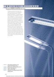
* External conduit seal required only on 1 inch hub size in Division 1, Group B within 5 feet (1.5 meters).<br />
<strong>Malux</strong> Finl<strong>and</strong> <strong>Oy</strong>, P.O.Box 69, FI-06151 PORVOO, FINLAND<br />
phone: +358 19 5745 700, fax: +358 19 5745 750, e-mail: info@malux.fi, web: www.malux.fi
EFS Factory Sealed Pilot Lights<br />
Pushbutton, Selector Switch <strong>Stations</strong><br />
– Section 5C<br />
Pilot lights listed below are factory sealed <strong>and</strong> do not require external<br />
seals*. Lamps are 6 watt, type S6, c<strong>and</strong>elabra base for use on 110-125<br />
volt circuits.<br />
LED pilot lights can be provided in place of st<strong>and</strong>ard inc<strong>and</strong>escent<br />
lamps by adding suffix LED after the color symbols. See Options on<br />
page 386<br />
Enclosures with single pilot covers only can be equipped with a<br />
transformer for each lamp for high voltages as shown.<br />
Transformer Voltages Above 125<br />
Nominal Volts Primary Cat.<br />
50-60 hertz Voltage No.<br />
Transformer Range Suffix<br />
220/110 220-240 T2<br />
440/110 440-480 T4<br />
550/110 550-600 T5<br />
Cl. I, Div. 1 & 2, Groups B*,C,D<br />
Cl. II, Div. 1, Groups E,F,G<br />
Cl. II, Div. 2, Groups F,G<br />
Cl. III<br />
NEMA 3,7B*CD,9EFG<br />
EFS Single Gang<br />
US: 1-866-764-5454 CAN: 1-800-265-0502 Copyright © 2006 Cooper Crouse-Hinds<br />
Explosionproof<br />
Dust-Ignitionproof<br />
Raintight<br />
Wet Locations<br />
Enclosure with Single Pilot Light�<br />
Hub Dead End Through Feed<br />
Size Cat. # Cat. #<br />
1 ⁄2 EFS11524-† EFSC11524-†<br />
3 ⁄4 EFS21524-† EFSC21524-†<br />
1 EFS31524-† EFSC31524-†<br />
Enclosure with Double Pilot Lights�<br />
1 ⁄2 EFS11561-† EFSC11561-†<br />
3 ⁄4 EFS21561-† EFSC21561-†<br />
1 EFS31561-† EFSC31561-†<br />
Dimensions (inches) Dimensions are approximate, not for construction purposes.<br />
Hub Dim. Dim.<br />
Size ‘‘h’’ ‘‘i’’<br />
1 ⁄2 3 ⁄4 13 ⁄16<br />
3 ⁄4 7 ⁄8 13 ⁄16<br />
1 1 15 ⁄16<br />
Typical body<br />
side view<br />
<strong>4C</strong><br />
* External conduit seal required for 1 inch hub size in Division 1, Group B within 5 feet (1.5<br />
meters) of enclosure.<br />
† Add color symbol for each pilot light from table below. Example: EFS11561 with red <strong>and</strong><br />
green lights is EFS11561-J1-J3<br />
Color Symbol Color Symbol Color Symbol<br />
Red J1 Amber J6 Blue J11<br />
Green J3 Clear J10<br />
�LED pilot lights can be furnished in place of st<strong>and</strong>ard inc<strong>and</strong>escent pilot lamps. Add suffix<br />
LED to catalog number after color symbol.<br />
Front view Cover †<br />
Surface covers have same length <strong>and</strong> width dimensions as bodies.<br />
<strong>Malux</strong> Finl<strong>and</strong> <strong>Oy</strong>, P.O.Box 69, FI-06151 PORVOO, FINLAND<br />
phone: +358 19 5745 700, fax: +358 19 5745 750, e-mail: info@malux.fi, web: www.malux.fi<br />
387
<strong>4C</strong> FlexStation TM <strong>Control</strong> Station<br />
Components<br />
Application:<br />
Five modular components - operators,<br />
contact blocks, covers, legend plates, <strong>and</strong><br />
bodies - are combined to provide a variety of<br />
control stations which are:<br />
� For use indoors or outdoors, in areas which<br />
are hazardous due to the presence of<br />
flammable gases <strong>and</strong> vapors, or combustible<br />
dust.<br />
� Used in conjunction with magnetic starters<br />
or contactors for remote control of motors<br />
<strong>and</strong> other electrical apparatus.<br />
� For installation in petroleum refineries,<br />
chemical petrochemical, <strong>and</strong> other industrial<br />
process facilities; grain processing <strong>and</strong><br />
storage facilities; <strong>and</strong> other heavy industrial<br />
applications where Class I, Class II, or<br />
Class III hazards are present.<br />
Features:<br />
� Momentary contact pushbuttons,<br />
maintained contact pushbuttons, <strong>and</strong> pilots<br />
lights offer a choice of functions.<br />
� Selector switches in 2 or 3 position<br />
configurations including keyed <strong>and</strong> spring<br />
return options.<br />
� Single-hole, two-hole, <strong>and</strong> three-hole<br />
covers for one, two, or three devices<br />
respectively per station.<br />
� Rugged control devices for safe, reliable<br />
operation in industrial applications.<br />
� Bodies, with extra room for wire pulling <strong>and</strong><br />
termination, also include two integral<br />
mounting feet for fast, secure installation.<br />
� Bodies have 1 ⁄2�, 3 ⁄4�, or 1� dead-end or<br />
through-feed conduit hubs with integral<br />
bushing for protection of wire insulation.<br />
� Covers <strong>and</strong> bodies are available in Feraloy ®<br />
or copper-free aluminum for light weight <strong>and</strong><br />
corrosion resistance.<br />
� DL legend plates have large lettering to give<br />
clear indication of device function. Space is<br />
available for field markings.<br />
St<strong>and</strong>ard Materials:<br />
� Bodies, covers - Feraloy ® or copper-free<br />
aluminum.<br />
� Pushbuttons <strong>and</strong> guards - Type 6/6 nylon.<br />
� Operating shafts, bearings - Stainless Steel.<br />
St<strong>and</strong>ard Finishes:<br />
� Feraloy ® iron-alloy - electrogalvanized <strong>and</strong><br />
aluminum acrylic paint.<br />
� Copper-free aluminum - natural.<br />
� Stainless Steel - natural.<br />
Electrical Ratings:<br />
� Pushbuttons <strong>and</strong> selector switches - 600<br />
VAC heavy duty (NEMA A600).<br />
� Pilot lights - 120 VAC.<br />
Certifications <strong>and</strong><br />
Compliances:<br />
� NEC: Class I, Div. 1&2, Groups B*<br />
(Div. 2), C, D<br />
Class II, Div. 1&2, Groups E, F, G<br />
Class III<br />
� Zone 1&2 Groups IIB*<br />
� NEMA: 3R, 7B (Div. 2)CD, 9EFG, 12<br />
� UL St<strong>and</strong>ard: 698<br />
* For Class I, Division 1, Group B or Zone 1 Hydrogen<br />
applications, use the EFS(C) complete control station<br />
catalog numbers found in Section 5C.<br />
Dimensions** (Inches):<br />
388 US: 1-866-764-5454 CAN: 1-800-265-0502 Copyright © 2006 Cooper Crouse-Hinds<br />
Class I, Div. 1 & 2, Groups B (Div. 2 only)* C, D<br />
Class II, Div. 1 & 2, Groups E, F, G<br />
Class III<br />
Zone 1 & 2 Groups IIB*<br />
NEMA 3R, 7B*(Div. 2)CD, 9 EFG, 12<br />
<strong>Malux</strong> Finl<strong>and</strong> <strong>Oy</strong>, P.O.Box 69, FI-06151 PORVOO, FINLAND<br />
phone: +358 19 5745 700, fax: +358 19 5745 750, e-mail: info@malux.fi, web: www.malux.fi<br />
Options:<br />
Description Suffix<br />
� Corro-free TM epoxy finish for use in severely<br />
corrosive environments.<br />
FlexStation covers <strong>and</strong> bodies.........S752
FlexStation TM <strong>Control</strong> Station<br />
Components<br />
Ordering Information<br />
STEP 1 – Select operator<br />
Pushbutton front operated, st<strong>and</strong>ard black button<br />
Pilot Light factory sealed, inc<strong>and</strong>escent lamp<br />
Selector Switch with st<strong>and</strong>ard lockout<br />
STEP 2 – Select contact block (if required)<br />
Contact Block<br />
Class I, Div. 1 & 2, Groups B (Div. 2 only) C, D<br />
Class II, Div. 1 & 2, Groups E, F, G<br />
Class III<br />
NEMA 3R, 7B(Div. 2)CD, 9EFG, 12<br />
IEC Zone 1 & 2 Groups IIB<br />
Description Cat. #<br />
Single button for 1 contact block DEV11<br />
Single button for 2 contact blocks DEV12<br />
Double buttons for 2 contact blocks DEV22<br />
Options Suffix to be added to Cat. #<br />
Specify color for each pushbutton button (ex: DEV11G, DEV22GR).<br />
Color is black if unspecified.<br />
Green button (unmarked) G<br />
Red button (unmarked) R<br />
Momentary red mushroom head style (not available with<br />
lockout or with DEV22) S111<br />
Lockout with bar <strong>and</strong> chain (available on DEV11 <strong>and</strong> DEV12) S153<br />
Maintained red mushroom head style (lockout comes<br />
st<strong>and</strong>ard, do not specify S153; not available on DEV22) S769<br />
Description Cat. #<br />
Pilot light with red jewel DEV30 J1<br />
Pilot light with green jewel DEV30 J3<br />
Pilot light with amber jewel DEV30 J6<br />
Pilot light with clear jewel DEV30 J10<br />
Pilot light with blue LED <strong>and</strong> clear jewel DEV30 J11–LED<br />
Options Suffix to be added to Cat. #<br />
LED lamps (st<strong>and</strong>ard clear jewel with colored lamp) LED<br />
24 V lamp (not available with transformer feature) S300<br />
240/120 V pilot light transformer T2<br />
480/120 V pilot light transformer T4<br />
600/120 V pilot light transformer T5<br />
Description Cat. #<br />
2-position (pos. 1 – N.O., pos. 2 – N.C.) for use with 1 or 2 contact blocks DEV42<br />
3-position (pos. 1 – N.O., pos. 2 – Open, pos. 3 – N.C.) for use with 1 or 2 contact blocks DEV43<br />
3-position (pos. 1 – N.C., pos. 2 – N.O., pos. 3 – N.O. for Switch A)<br />
(pos. 1 – N.O., pos. 2 – N.O., pos. 3 – N.C. for Switch B) for use with 2 contact blocks DEV44<br />
Options Suffix to be added to Cat. #<br />
Spring return to center from right (For DEV43 or DEV44 only) S634<br />
Spring return to center from left (For DEV43 or DEV44 only) S635<br />
Spring return to center from right <strong>and</strong> left (For DEV43 or DEV44 only) S842<br />
Key Operated – removable from all positions<br />
Key Operated – removable from left position for DEV42<br />
S847 K1<br />
or from center for DEV43 <strong>and</strong> DEV44<br />
Key Operated – removable from right position for DEV42<br />
S847 K2<br />
or from left for DEV43 <strong>and</strong> DEV44 S847 K3<br />
Key Operated – removable from right position for DEV43 <strong>and</strong> DEV44 S847 K4<br />
Description Cat. #<br />
Contact block, 1 NO/1 NC, 10A, 600VAC, A600 rating ESWP126<br />
*Each control station will accept a maximum of three contact blocks. Select device operators accordingly. DEV12, DEV22 <strong>and</strong> DEV44 may not<br />
be used on a three-operator (DS443-SA) cover. DEV42 <strong>and</strong> DEV43 may not be used on a three-operator cover when using them with two<br />
contact blocks.<br />
US: 1-866-764-5454 CAN: 1-800-265-0502 Copyright © 2006 Cooper Crouse-Hinds<br />
<strong>Malux</strong> Finl<strong>and</strong> <strong>Oy</strong>, P.O.Box 69, FI-06151 PORVOO, FINLAND<br />
phone: +358 19 5745 700, fax: +358 19 5745 750, e-mail: info@malux.fi, web: www.malux.fi<br />
<strong>4C</strong><br />
389
<strong>4C</strong> FlexStation TM <strong>Control</strong> Station<br />
Components<br />
Ordering Information<br />
STEP 3 – Select desired legend plates<br />
Device Legend Plates – for special markings order DL01 – ‘‘desired marking’’<br />
STEP 4 – Select Cover<br />
Covers<br />
Class I, Div. 1 & 2, Groups B (Div. 2 only) C, D<br />
Class II, Div. 1 & 2, Groups E, F, G<br />
Class III<br />
NEMA 3R, 7B(Div. 2)CD, 9EFG, 12<br />
IEC Zone 1 & 2 Groups IIB<br />
Cat. # Inscription Cat. # Inscription<br />
DL01<br />
DL02<br />
DL03<br />
DL16<br />
DL21<br />
DL23<br />
DL17<br />
DL46<br />
DL18<br />
DL15<br />
DL24<br />
DL10<br />
DL27<br />
DL08<br />
DL07<br />
DL20<br />
DL25<br />
DL14<br />
DL26<br />
DL12<br />
DL19<br />
DL09<br />
DL85<br />
DL47<br />
DL05<br />
DL06<br />
DL13<br />
DL11<br />
DL22<br />
Blank w/no fields<br />
Blank w/single field<br />
Blank w/2 fields<br />
Automatic<br />
Close<br />
Down<br />
Emergency Stop<br />
Fast<br />
Forward<br />
H<strong>and</strong><br />
In<br />
Jog<br />
Lower<br />
Off<br />
On<br />
Open<br />
Out<br />
Power On<br />
Raise<br />
Reset<br />
Reverse<br />
Run<br />
Safe<br />
Slow<br />
Start<br />
Stop<br />
Test<br />
Trip<br />
Up<br />
DL97<br />
DL95<br />
DL92<br />
DL30<br />
DL29<br />
DL35<br />
DL93<br />
DL98<br />
DL48<br />
DL91<br />
DL32<br />
DL36<br />
DL28<br />
DL33<br />
DL86<br />
DL65<br />
DL96<br />
DL37<br />
DL90<br />
DL99<br />
DL94<br />
390 US: 1-866-764-5454 CAN: 1-800-265-0502 Copyright © 2006 Cooper Crouse-Hinds<br />
Alarm-Silence<br />
Auto-Manual<br />
Fast-Slow<br />
Forward-Reverse<br />
H<strong>and</strong>-Auto<br />
In-Out<br />
Local-Remote<br />
Maint-Manual<br />
Off-On<br />
On-Off<br />
Open-Close<br />
Raise-Lower<br />
Run-Jog<br />
Up-Down<br />
Safe-Run<br />
Slow-Fast<br />
Start-Emergency Stop<br />
Start-Stop<br />
Stop-Start<br />
Test-Reset<br />
Trip-Reset<br />
Description Cat. #<br />
Blank cover with single hole (Single gang) DS441<br />
Blank cover with 2 holes (Single gang)<br />
Blank cover with 3 holes (To be used with EFD(C)1491-SA, 2491-SA or<br />
DS442<br />
3491-SA series of back boxes)<br />
Replacement cover plug for unused device operator<br />
DS443-SA<br />
openings 0206765<br />
Options<br />
Aluminum body (m<strong>and</strong>atory suffix on DS443<br />
Suffix to be added to Cat. #<br />
must be included in catalog number SA<br />
Exterior epoxy powder coat finish<br />
Interior & exterior epoxy powder coat finish. Not<br />
S752<br />
available on three operator cover (DS443-SA) S753<br />
<strong>Malux</strong> Finl<strong>and</strong> <strong>Oy</strong>, P.O.Box 69, FI-06151 PORVOO, FINLAND<br />
phone: +358 19 5745 700, fax: +358 19 5745 750, e-mail: info@malux.fi, web: www.malux.fi
FlexStation TM <strong>Control</strong> Station<br />
Components<br />
Ordering Information<br />
Class I, Div. 1 & 2, Groups B (Div. 2 only) C, D<br />
Class II, Div. 1 & 2, Groups E, F, G<br />
Class III<br />
NEMA 3R, 7B(Div. 2)CD, 9EFG, 12<br />
IEC Zone 1 & 2 Groups IIB<br />
STEP 5 – Select back box<br />
Back Boxes (for use with DS441 <strong>and</strong> DS442 covers or with 1 gang <strong>and</strong> 2 gang DS/DSD Series covers)<br />
Dead End Through Feed Hub Size Back Box Arrangement<br />
EDS171 EDSC171 1 ⁄2� Single gang back box<br />
EDS271 EDSC271 3 ⁄4� Single gang back box<br />
EDS371 EDSC371 1� Single gang back box<br />
EDS172 EDSC172 1 ⁄2� Double gang back box<br />
EDS272 EDSC272 3 ⁄4� Double gang back box<br />
EDS372 EDSC372 1� Double gang back box<br />
Options Suffix to be added to Cat. #<br />
Aluminum Body SA<br />
Exterior epoxy powder coat finish S752<br />
Interior & exterior epoxy powder coat finish S753<br />
Back Boxes (for use with DS443-SA cover or with 1 ⁄2 gang DS511 (3-operator) Series covers)<br />
Dead End Through Feed Hub Size Back Box Arrangement<br />
EFD1491-SA EFDC1491-SA 1 ⁄2� 11 ⁄2 gang back box<br />
EFD2491-SA EFDC2491-SA 3 ⁄4� 11 ⁄2 gang back box<br />
EFD3491-SA EFDC3491-SA 1� 11 ⁄2 gang back box<br />
Options Suffix to be added to Cat. #<br />
Exterior epoxy powder coat finish S752<br />
Interior & exterior epoxy powder coat finish S753<br />
US: 1-866-764-5454 CAN: 1-800-265-0502 Copyright © 2006 Cooper Crouse-Hinds<br />
<strong>Malux</strong> Finl<strong>and</strong> <strong>Oy</strong>, P.O.Box 69, FI-06151 PORVOO, FINLAND<br />
phone: +358 19 5745 700, fax: +358 19 5745 750, e-mail: info@malux.fi, web: www.malux.fi<br />
<strong>4C</strong><br />
391
<strong>4C</strong> EDSCM Modular Multi-Gang<br />
<strong>Control</strong> Device Bodies<br />
Dimensions Pg. 393<br />
For use with DSD device cover sub-assemblies<br />
listed on catalog pages 394 to 396.<br />
Applications:<br />
Modular control device bodies are for surface<br />
mounting combinations of control device<br />
equipment for use in:<br />
� Industrial areas such as chemical plants, oil<br />
<strong>and</strong> gas refineries, paint <strong>and</strong> varnish<br />
manufacturing plants, gasoline bulk loading<br />
terminals, grain elevators, grain processing<br />
industries, coal processing or h<strong>and</strong>ling areas<br />
where atmospheres may contain hazardous<br />
gases or dusts, <strong>and</strong> arcing of enclosed<br />
devices must not ignite the surrounding<br />
atmosphere.<br />
� Conjunction with magnetic starters or<br />
contactors for remote control <strong>and</strong> monitoring<br />
of motors.<br />
� Manual starting <strong>and</strong> stopping of small AC or<br />
DC motors.<br />
� <strong>Control</strong>ling <strong>and</strong> supplying energy to<br />
portable electrical devices such as motor<br />
generator sets, compressors, conveyors,<br />
portable tools, etc.<br />
Features:<br />
EDSCM Modular <strong>Control</strong> <strong>Stations</strong> have many<br />
distinct advantages over multiple individual<br />
units:<br />
� Reduce installation costs. A multi-gang<br />
device assembly can be installed in less time<br />
than several single-gang units.<br />
� Seals not required between gangs.<br />
� Improved appearance. No exposed conduit<br />
runs between devices.<br />
� Light weight. Fifteen-gang aluminum device<br />
body can be installed by one person.<br />
� Mounting feet are provided on the top <strong>and</strong><br />
bottom of every gang to facilitate installation.<br />
� Two <strong>and</strong> three gang t<strong>and</strong>em bodies have<br />
1 1 ⁄4� thru-feed inward horizontal hubs <strong>and</strong> 1�<br />
or 2� vertical thru-feed hubs. Pipe plugs are<br />
installed in one horizontal hub <strong>and</strong> both<br />
vertical hubs.<br />
� Single-gang device bodies have 1� thrufeed<br />
inward horizontal hubs <strong>and</strong> 3 ⁄4� thru-feed<br />
vertical hubs. Pipe plugs are installed in one<br />
horizontal hub <strong>and</strong> both vertical hubs.<br />
� All hubs are taper tapped <strong>and</strong> have integral<br />
bushings.<br />
� Close nipples, which are used to join two or<br />
more device bodies together, are furnished<br />
with EDSCM 21, 32, 33, 62 <strong>and</strong> 63 units.<br />
� Any combination of bodies can be joined<br />
together horizontally.<br />
St<strong>and</strong>ard Materials:<br />
� Copper-free aluminum<br />
Finish:<br />
� Natural<br />
Certifications <strong>and</strong><br />
Compliances:<br />
(When used with DSD device<br />
sub-assemblies)�:<br />
Class I, Division 1 & 2,<br />
Groups C,D<br />
Class I, Division 2,<br />
Group B,C,D<br />
Class II, Division 1,<br />
Groups E,F,G<br />
Class II, Division 2, Groups F,G<br />
Class III<br />
NEMA/EEMAC<br />
3,7B(Div.2)CD,9EFG<br />
U.L. St<strong>and</strong>ard 894, 698<br />
� CSA St<strong>and</strong>ard: C22.2 No. 30<br />
NOTE: In Class I areas all conduit runs<br />
entering bodies must be sealed. As many<br />
as five bodies can be joined horizontally<br />
without an intervening seal.<br />
Series EDSCM<br />
The EDSCM Series consists of five basic<br />
device bodies that can be joined together to<br />
make multi-gang control stations.<br />
Cl. I, Div. 1, Groups C,D�<br />
Cl. I, Div. 2, Groups B,C,D<br />
Cl. II, Div. 1, Groups E,F,G<br />
Cl. II, Div. 2, Groups F,G<br />
Cl. III<br />
NEMA 3,7B(Div. 2)CD,9EFG<br />
EDSCM21 EDSCM32 EDSCM62 EDSCM33 EDSCM63<br />
Description<br />
Thru-Feed<br />
Hub Size Cat. #<br />
Single Gang 3 ⁄4� EDSCM21<br />
T<strong>and</strong>em Two Gang 1� EDSCM32<br />
T<strong>and</strong>em Two Gang 2� EDSCM62<br />
T<strong>and</strong>em Three Gang 1� EDSCM33<br />
T<strong>and</strong>em Three Gang 2� EDSCM63<br />
392 US: 1-866-764-5454 CAN: 1-800-265-0502 Copyright © 2006 Cooper Crouse-Hinds<br />
Explosionproof<br />
Dust-Ignitionproof<br />
Raintight<br />
Wet Locations<br />
� When a CPS receptacle cover device is used, the assembly meets requirements for Class I,<br />
Groups C <strong>and</strong> D areas only.<br />
<strong>Malux</strong> Finl<strong>and</strong> <strong>Oy</strong>, P.O.Box 69, FI-06151 PORVOO, FINLAND<br />
phone: +358 19 5745 700, fax: +358 19 5745 750, e-mail: info@malux.fi, web: www.malux.fi
EDSCM Modular Multi-Gang<br />
<strong>Control</strong> Device Bodies<br />
Dimensions (inches):<br />
EDSCM21<br />
EDSCM32<br />
EDSCM33<br />
Cl. I, Div. 1, Groups C,D�<br />
Cl. I, Div. 2, Groups B,C,D<br />
Cl. II, Div. 1, Groups E,F,G<br />
Cl. II, Div. 2, Groups F,G<br />
Cl. III<br />
NEMA 3,7B(Div. 2)CD,9EFG<br />
US: 1-866-764-5454 CAN: 1-800-265-0502 Copyright © 2006 Cooper Crouse-Hinds<br />
Explosionproof<br />
Dust-Ignitionproof<br />
Raintight<br />
Wet Locations<br />
EDSCM62<br />
EDSCM63<br />
� When a CPS receptacle cover device is used, the assembly meets requirements for Class I, Groups C <strong>and</strong> D areas only. Receptacles comply with U.L. St<strong>and</strong>ard 886 only.<br />
* Dimensions are approximate, not for construction purposes.<br />
<strong>Malux</strong> Finl<strong>and</strong> <strong>Oy</strong>, P.O.Box 69, FI-06151 PORVOO, FINLAND<br />
phone: +358 19 5745 700, fax: +358 19 5745 750, e-mail: info@malux.fi, web: www.malux.fi<br />
<strong>4C</strong><br />
393
<strong>4C</strong> DSD Cover <strong>and</strong> Device<br />
Sub-Assemblies<br />
For use with EDSCM modular control<br />
device bodies listed on catalog page 392<br />
<strong>and</strong> EDS/EDSC back boxes on page 397.<br />
Features:<br />
� Large machine screws for fastening covers<br />
to bodies<br />
� Lockout hole for padlock having 1 ⁄4� hasp is<br />
provided when used with covers for front<br />
lever <strong>and</strong> side rocker type operation<br />
� Lockout provisions on front operated<br />
pushbutton (marked ‘‘STOP’’ <strong>and</strong> ‘‘OFF’’)<br />
<strong>and</strong> all selector switch covers<br />
� For covers with front lever <strong>and</strong> side rocker<br />
type operating h<strong>and</strong>les, threaded type shafts<br />
<strong>and</strong> bushings are used to ensure<br />
flametightness<br />
� Accurately ground flange for flametight joint<br />
when mated with ground flange on back box<br />
St<strong>and</strong>ard Materials:<br />
� Covers, front operated – Feraloy iron alloy<br />
<strong>and</strong> copper-free aluminum<br />
� Covers, side operated – Copper-free<br />
aluminum<br />
� Shafts <strong>and</strong> shaft bushings – stainless steel<br />
� Rocker h<strong>and</strong>les, pushbuttons <strong>and</strong> guards –<br />
type 6/6 nylon<br />
� Sealing enclosures – copper-free aluminum<br />
CPS delayed action receptacle cover:<br />
� Receptacle housing – copper-free<br />
aluminum<br />
� Insulation – diallyl phthalate (DAP)<br />
� Contacts – brass<br />
St<strong>and</strong>ard Finishes:<br />
� Feraloy – electrogalvanized <strong>and</strong> aluminum<br />
acrylic paint<br />
� Copper-free aluminum – natural<br />
Manual Motor Starters<br />
Max.<br />
Poles Max. H.P. Volts A.C. Cat. #<br />
With Allen-Bradley Bulletin 600 Switches**<br />
1 1 115-230 DSD910<br />
2 1 115-230 DSD911<br />
With General Electric Switches**<br />
1 1 115-230 DSD912§<br />
2 1 115-230 DSD913§<br />
With Cutler-Hammer Switches**<br />
1 1 115-230 DSD914§<br />
2 1 115-230 DSD915§<br />
With Arrow-Hart Switches<br />
Without Overload Protection<br />
2 5 250 (30A) DSD916<br />
2 7.5 600 (30A) DSD916<br />
3 7.5 250 (30A) DSD917<br />
3 15 600 (20A) DSD917<br />
394 US: 1-866-764-5454 CAN: 1-800-265-0502 Copyright © 2006 Cooper Crouse-Hinds<br />
Cl. I. Div. 1&2, Groups B*, C, D�Explosionproof<br />
Cl. II, Div. 1, Groups E, F, G Dust-Ignitionproof<br />
Cl. II, Div. 2, Groups F, G Raintight<br />
Cl. III<br />
Wet Locations<br />
NEMA 3, 7B*CD, 9EFG<br />
Certifications <strong>and</strong><br />
Compliances:<br />
(When used with EDSCM & EDS bodies):<br />
� NEC/CEC:<br />
Class I, Division 1 & 2, Groups C, D�<br />
Class I, Division 2, Groups B, C, D<br />
Class II, Division 1, Groups E, F, G<br />
Class II, Division 2, Groups F, G<br />
Class III<br />
� NEMA/EEMAC: 3, 7B(Div. 2)CD, 9EFG<br />
� UL St<strong>and</strong>ard: 894, 698<br />
� CSA St<strong>and</strong>ard: C22.2 No. 30<br />
Pushbuttons, Pilot Lights & Selector<br />
Switches:<br />
(When used with EFS bodies):<br />
� NEC/CEC:<br />
Class I, Division 1 & 2, Groups B, C, D<br />
Class II, Division 1, Groups E, F, G<br />
Class II, Division 2, Groups F, G<br />
Class III<br />
� NEMA/EEMAC: 3, 7BCD, 9EFG<br />
� UL St<strong>and</strong>ard: 894, 698<br />
� CSA St<strong>and</strong>ard: C22.2 No. 30<br />
Options:<br />
The following special options are<br />
available by adding suffix to Cat. No.: Suffix to be<br />
Added to Cover<br />
Description Cat. #<br />
Lockout provision on front operated pushbutton cover (st<strong>and</strong>ard on buttons<br />
marked ‘‘STOP’’ <strong>and</strong> ‘‘OFF’’) ......................................................S153<br />
Three-position selector switches with modified operation:<br />
Momentary contact clockwise operation, spring return to center,<br />
maintained contact counter-clockwise operation...................................S634<br />
Momentary contact counter-clockwise operation, spring return to<br />
center, maintained contact clockwise operation....................................S635<br />
Emergency ‘‘STOP’’ button momentary – front operated mushroom button breaks normally<br />
closed contacts ..................................................................S111<br />
Bodies <strong>and</strong> covers – copper-free aluminum ...........................................SA<br />
For 24 VDC operation on pilot lights ................................................S300<br />
Maintained contact mushroom head with lockout <strong>and</strong> guard. ..........................S769<br />
* For pushbuttons, pilot lights, & selector switches, use EFS back box with required external conduit seal for 1 inch hub size,<br />
within 5 feet for Class I, Division 1, Group B applications.<br />
� When a CPS receptacle cover device is used, the assembly meets<br />
requirements for Class I, Groups C <strong>and</strong> D areas only. Receptacles comply<br />
with U.L. St<strong>and</strong>ard 886 only.<br />
§ A comparable factory sealed cover will fit on the EDSCM21 body, EDS<br />
<strong>and</strong> EDSC bodies (listed on page 397), <strong>and</strong> in bottom gang of EDSCM33<br />
<strong>and</strong> EDSCM63 bodies. To order, add suffix S701 to catalog number.<br />
** Includes one interchangeable heater. Select heater (from tables on<br />
pages 356 <strong>and</strong> 357). Symbol 0 (zero) may be used to indicate heater<br />
omitted.<br />
<strong>Malux</strong> Finl<strong>and</strong> <strong>Oy</strong>, P.O.Box 69, FI-06151 PORVOO, FINLAND<br />
phone: +358 19 5745 700, fax: +358 19 5745 750, e-mail: info@malux.fi, web: www.malux.fi
DSD Cover <strong>and</strong> Device<br />
Sub-Assemblies<br />
DSD918 DSD921 DSD933 DSD962 DSD970<br />
For use with EDSCM modular control device<br />
bodies listed on catalog page 392 & EFS/EDS back boxes<br />
listed on catalog page 397.<br />
Front Operated Pushbutton <strong>Stations</strong><br />
600 VAC Heavy Duty, Factory Sealed<br />
Number of Normal<br />
Cover Buttons Position Diagram Cat. #§<br />
1 1 Circuit<br />
Universal DSD918<br />
1 2 Circuits<br />
Universal DSD919<br />
2 Circuits**<br />
Cl. I. Div. 1&2, Groups B*,C,D�<br />
Cl. II, Div. 1, Groups E,F,G<br />
Cl. II, Div. 2, Groups F,G<br />
Cl. III<br />
NEMA 3,7B*CD,9EFG<br />
DSD920**<br />
2 2 Circuits<br />
Universal DSD921<br />
2 2 Circuits**<br />
Start-Stop<br />
unless<br />
otherwise<br />
specified DSD922**<br />
2 2 Circuits<br />
Universal<br />
Mushroom Head DSD970<br />
3 3 Circuits<br />
Universal DSD962<br />
Front Operated General Use Snap Switch<br />
Amperes<br />
Style 120 VAC 277 VAC Cat. #<br />
1-Pole 20 20 DSD933‡<br />
2-Pole 20 20 DSD934‡<br />
3-Pole �� �� DSD935***<br />
3-Way 20 20 DSD936‡<br />
4-Way 20 20 DSD937‡<br />
1-Pole 30 30 DSD939***<br />
2-Pole 30 30 DSD940***<br />
3-Way 30 30 DSD941***<br />
*** Cannot be factory sealed.<br />
��16 Amp., 125V.<br />
10 Amp., 250V.<br />
** Two universal contact blocks, must be wired as two circuits with one normally open <strong>and</strong><br />
one normally closed.<br />
‡ To order a comparable factory sealed cover for EDS, EDSC, EDSCM21 <strong>and</strong> the bottom gang<br />
of EDSCM33 <strong>and</strong> EDSCM63 bodies, add suffix S697.<br />
* See note on catalog page 394 for Division 1, Group B applications.<br />
CPS152R<br />
US: 1-866-764-5454 CAN: 1-800-265-0502 Copyright © 2006 Cooper Crouse-Hinds<br />
Explosionproof<br />
Dust-Ignitionproof<br />
Raintight<br />
Wet Locations<br />
Delayed Action Receptacles<br />
Factory Sealed<br />
Rating Cat. #<br />
20 A, 1 HP, 125-250 VAC<br />
60 Hertz<br />
20 A, 18 VDC<br />
30 A, 1 1 ⁄2 HP,<br />
125-250 VAC<br />
60 Hertz; 7 A,<br />
1 ⁄2 HP, 480 VAC,<br />
60 Hertz<br />
30 A, 3 HP, 125-250 VAC<br />
60 Hertz; 7A,<br />
1 HP, 480 VAC,<br />
60 Hertz<br />
ENR5201<br />
CPS152R<br />
(2 wire, 3 pole)<br />
CPS532R<br />
(2 wire, 3 pole)<br />
CPS732R<br />
(3 wire, 4 pole)<br />
General Purpose, Dead Front, Factory<br />
Sealed<br />
Rating Cat. #<br />
20 A, 125 VAC ENR5201<br />
20 A, 250 VAC ENR6202<br />
NEMA<br />
Config.<br />
5-20R<br />
6-20R<br />
<strong>4C</strong><br />
� When a CPS receptacle cover device is used, the assembly meets requirements for Class<br />
I, Groups C <strong>and</strong> D areas only.<br />
§ Specify marking required for external pushbuttons or nylon rocker h<strong>and</strong>les. St<strong>and</strong>ard<br />
markings available, are as follows:<br />
START<br />
STOP<br />
ON<br />
EMERGENCY<br />
FORWARD<br />
REVERSE<br />
OFF<br />
RUN<br />
JOG<br />
OPEN<br />
CLOSE<br />
UP<br />
<strong>Malux</strong> Finl<strong>and</strong> <strong>Oy</strong>, P.O.Box 69, FI-06151 PORVOO, FINLAND<br />
phone: +358 19 5745 700, fax: +358 19 5745 750, e-mail: info@malux.fi, web: www.malux.fi<br />
RESET<br />
TRIP<br />
TEST<br />
DOWN<br />
IN<br />
OUT<br />
LIGHT ON<br />
HAND<br />
AUTOMATIC<br />
RAISE<br />
LOWER<br />
395
<strong>4C</strong> DSD Cover <strong>and</strong> Device<br />
Sub-Assemblies<br />
Cl. I, Div. 1&2, Groups B*,C,D<br />
Cl. II, Div. 1, Groups E,F,G<br />
Cl. II, Div. 2, Groups F,G<br />
Cl. III<br />
NEMA 3,7B*CD,9EFG<br />
396 US: 1-866-764-5454 CAN: 1-800-265-0502 Copyright © 2006 Cooper Crouse-Hinds<br />
Explosionproof<br />
Dust-Ignitionproof<br />
Raintight<br />
Wet Locations<br />
DSD951 DSD925 DSD947-J1-J1 DSD958 DSD957 DSD961-J1<br />
For use with EDSCM modular control device<br />
bodies listed on catalog page 392 & EFS/EDS back boxes<br />
listed on catalog page 397.<br />
Side Operated Pushbutton Station<br />
600 VAC Heavy Duty, Factory Sealed<br />
Normal<br />
Position Diagram Cat. #§<br />
1 Circuit Universal DSD949<br />
2 Circuits Universal DSD950<br />
2 Circuits<br />
1 Open - A<br />
1 Closed - B<br />
Start-Stop unless<br />
otherwise specified DSD951<br />
Selector Switches<br />
Maintained Contact 600 VAC Heavy Duty<br />
Two<br />
Position<br />
Three<br />
Position<br />
Position Position Position<br />
Style 1 2 3 Cat. #††<br />
Two<br />
Circuit<br />
Four<br />
Circuit<br />
Two<br />
Circuit<br />
Four<br />
Circuit<br />
DSD923<br />
DSD924<br />
DSD925<br />
DSD926<br />
DSD927<br />
Pilot Light Devices�<br />
Factory Sealed<br />
Description Diagram Cat. #<br />
With one pilot light<br />
With two pilot lights<br />
(Not available with a<br />
DSD948-J†<br />
transformer)<br />
With one pilot light<br />
DSD947-J†-J†<br />
<strong>and</strong> transformer<br />
With one pilot light<br />
DSD948-J†-T**<br />
<strong>and</strong> pushbutton station<br />
With one pilot light<br />
DSD958-J†<br />
<strong>and</strong> 2 pushbutton station DSD961-J†<br />
With one pilot light &<br />
transformer <strong>and</strong> 2 pushbutton<br />
station DSD961-J†-T**<br />
Blank Cover<br />
Cat. # DSD957<br />
§ See table on page 395.<br />
†† Specify indicating plate markings.<br />
St<strong>and</strong>ard indicating plate markings available are as follows:<br />
Two-Position<br />
RUN, JOG FAST, SLOW IN, OUT<br />
HAND, AUTOMATIC OPEN, CLOSE RAISE, LOWER<br />
FORWARD, REVERSE<br />
Three-Position<br />
UP, DOWN<br />
ON, OFF<br />
START, STOP<br />
JOG, OFF, RUN 1, OFF, 2<br />
AUTOMATIC, OFF, HAND OPEN, OFF, CLOSE<br />
FORWARD, OFF, REVERSE<br />
FAST, OFF, SLOW<br />
UP, OFF, DOWN<br />
† Add color symbol for each pilot light from table below.<br />
Color Symbol Color Symbol Color Symbol<br />
Red J1 Amber J6 Blue J11<br />
Green J3 Clear J10<br />
** Add suffix below for transformer primary voltage:<br />
Transformers – Voltages above 125<br />
Nom. Volts Primary Suffix<br />
50-60 hertz Voltage Added to<br />
Transformer Range Cat. #<br />
220/110 220-240 T2<br />
440/110 440-480 T4<br />
550/110 550-600 T5<br />
� LED pilot lights can be furnished in place of st<strong>and</strong>ard inc<strong>and</strong>escent pilot lamps. Add suffix<br />
LED to Cat. No. after last color symbol.<br />
* See note on catalog page 394 for Division 1, Group B applications.<br />
<strong>Malux</strong> Finl<strong>and</strong> <strong>Oy</strong>, P.O.Box 69, FI-06151 PORVOO, FINLAND<br />
phone: +358 19 5745 700, fax: +358 19 5745 750, e-mail: info@malux.fi, web: www.malux.fi
EDS <strong>and</strong> EDSC Single <strong>and</strong><br />
Multi-Gang Device Bodies<br />
<strong>and</strong> EFS <strong>and</strong> EFSC Single<br />
Gang Device Bodies<br />
Both EFS <strong>and</strong> EFSC single gang body family<br />
<strong>and</strong> EDS <strong>and</strong> EDSC single <strong>and</strong> two-gang<br />
st<strong>and</strong>ard, two or three-gang t<strong>and</strong>em device<br />
bodies are designed for use with the DS<br />
covers listed below, <strong>and</strong> the DSD covers<br />
shown on pages 394 through 396.<br />
Single Gang<br />
Feraloy<br />
Deep – 211 ⁄16� Deep Shallow – 2� Deep<br />
Hub Dead End Through Feed Dead End Through Feed<br />
Size Cat. # Cat. # Cat. # Cat. #<br />
1 ⁄2� EDS171 EDSC171 EFS171 EFSC171<br />
3 ⁄4� EDS271 EDSC271 EFS271 EFSC271<br />
1� EDS371 EDSC371 EFS371 EFSC371<br />
Two Gang<br />
Feraloy<br />
Hub Dead End Through Feed<br />
Size Cat. # Cat. #<br />
1 ⁄2� EDS172 EDSC172<br />
3 ⁄4� EDS272 EDSC272<br />
1� EDS372 EDSC372<br />
Cl. I, Div. 1 & 2, Groups B,C,D�<br />
Cl. II, Div. 1, Groups E,F,G<br />
Cl. II, Div. 2, Groups F,G<br />
Cl. III<br />
NEMA 3,7B�CD,9EFG,12<br />
Single <strong>and</strong> two-gang st<strong>and</strong>ard bodies have<br />
external dead end or thru-feed conduit hubs,<br />
with integral bushings, in sizes 1 ⁄2�, 3 ⁄4� <strong>and</strong> 1�.<br />
T<strong>and</strong>em bodies have thru-feed 1� hubs.<br />
Each body contains 1 internal ground screw<br />
<strong>and</strong> boss per gang <strong>and</strong> external mounting<br />
feet.<br />
Order bodies <strong>and</strong> covers separately.<br />
Three Gang<br />
T<strong>and</strong>em<br />
Copper-free<br />
Aluminum<br />
Hub<br />
Size Cat. #<br />
1� EDSC378<br />
US: 1-866-764-5454 CAN: 1-800-265-0502 Copyright © 2006 Cooper Crouse-Hinds<br />
Explosionproof<br />
Dust-Ignitionproof<br />
Raintight<br />
Wet Locations<br />
Common Cover Assemblies<br />
<strong>4C</strong><br />
These covers may be used with the above bodies or as replacements<br />
for the cover portions of the control device assemblies listed on<br />
pages 392, 431, 435 & 436.<br />
Description Diagram Cat. #<br />
With one pilot light DS455-J†<br />
With one pilot light <strong>and</strong><br />
transformer DS476-J†-T‡<br />
With two pilot lights DS456-J†-J†<br />
With one push button DS429§<br />
With two push buttons DS454§<br />
With one push button <strong>and</strong><br />
one pilot light DS510-J†§<br />
� Subject to compliance limitations of device covers selected. Only EFS & EFSC bodies with the appropriate covers are for use in Div. 1, Group B areas.<br />
† Insert color symbol. See table on page 396.<br />
‡ Insert symbol for transformer primary voltage.<br />
See tables on page 396. Example: DS476 with red pilot light <strong>and</strong> 440 volt transformer is DS476-J1-T4.<br />
§ See marking requirements on page 395.<br />
<strong>Malux</strong> Finl<strong>and</strong> <strong>Oy</strong>, P.O.Box 69, FI-06151 PORVOO, FINLAND<br />
phone: +358 19 5745 700, fax: +358 19 5745 750, e-mail: info@malux.fi, web: www.malux.fi<br />
397
<strong>4C</strong> <strong>Control</strong> Station Covers<br />
Hinged <strong>and</strong> Open Front<br />
OPEN<br />
FRONT<br />
COVER<br />
398 US: 1-866-764-5454 CAN: 1-800-265-0502 Copyright © 2006 Cooper Crouse-Hinds<br />
HINGED<br />
COVER<br />
Added environmental protection for Cooper Crouse-Hinds ® control stations is now available from a patented ‘‘slip on’’ series of covers.<br />
Easy to install, these enclosures are available in hinged <strong>and</strong> open front styles.<br />
� Clear UV stabilized Lexan‡ polycarbonate plastic.<br />
� Allows the end-user to see enclosed controls.<br />
� Strong enough to withst<strong>and</strong> the rough treatment found in the industrial work place.<br />
� Ideal for corrosive <strong>and</strong> adverse areas providing added product endurance.<br />
� Short pay back period.<br />
� Downtime due to weather or accidental bumping is eliminated.<br />
� Plant shutdowns caused by inoperable or accidentally operated push button devices are non-existent.<br />
� Lock out/tag out capabilities.<br />
� For conformance to OSHA requirements.<br />
� Provides increased personnel safety.<br />
� Quick <strong>and</strong> easy slip on installation requires no tools.<br />
� Colored covers are available (e.g. red for emergency, yellow for fire alarm, etc.).<br />
<strong>Malux</strong> Finl<strong>and</strong> <strong>Oy</strong>, P.O.Box 69, FI-06151 PORVOO, FINLAND<br />
phone: +358 19 5745 700, fax: +358 19 5745 750, e-mail: info@malux.fi, web: www.malux.fi
<strong>Control</strong> Station Covers<br />
Hinged <strong>and</strong> Open Front<br />
SECURED ACCESS HINGED COVER<br />
APPLICATIONS:<br />
� High moisture areas due to weather, steam, or wash down<br />
procedures.<br />
� Areas where dirt, dust, mud, s<strong>and</strong>, etc. interferes with equipment<br />
operation.<br />
� Prevention of accidental equipment operation.<br />
� Instances requiring equipment lock out/tag out.<br />
FEATURES & BENEFITS:<br />
� Heavy duty, impact-resistant, polycarbonate cover with stainless<br />
steel or heavy duty Lexan hinge.<br />
� Clear material allows visibility of all controls.<br />
� Superior sealing provided by heavy-duty neoprene gaskets. Lock<br />
out/tag out ability provides personnel safety.<br />
� Unique patented design allows installation in seconds without any<br />
interruption of service.<br />
� Specific chemical resistant covers available (may not be clear) -<br />
consult factory for minimum order quantity.<br />
� Capability to engineer cover to fit any size device - consult factory.<br />
ORDERING INFORMATION:<br />
HINGED COVERS<br />
Single Gang Application Catalog Number<br />
EDS(C) <strong>and</strong> EFD(C) control stations NC-CH1<br />
EFS(C) control stations NC-CH1-EFS<br />
MC(C) control stations NC-CH1-MC<br />
FS(C) back box with cover assembly NC-CH1-FS<br />
FD(C) back box with cover assembly NC-CH1-FD<br />
EGF11 <strong>and</strong> EGF12 (Ground Fault) NC-CH1-EGF 11<br />
N2S(C) Krydon: 1 & 2 devices NC-CH1-N2S<br />
N2D(C) Krydon: 1 & 2 devices NC-CH1-N2D<br />
GHG432 control station NC-CH1-GHG<br />
Single Gang (Long) Application Catalog Number<br />
EFD(C) (3 device) NC-CH1-3L<br />
N2S(C) Krydon: 3 devices NC-CH1-N2S-3L<br />
N2S(C) Krydon: 4 devices NC-CH1-N2S-4L<br />
Double Gang Application Catalog Number<br />
EDS(C) control stations NC-CH2<br />
EDSCM32: 2 gang t<strong>and</strong>em NC-CH2L<br />
EDSCM33: 3 gang t<strong>and</strong>em NC-CH3L<br />
FS(C) back box with cover NC-CH2-FS<br />
FD(C) back box with cover NC-CH2-FD<br />
EDSC378 - 3 gang t<strong>and</strong>em assembly NC-CH1-MC3<br />
QUICK ACCESS OPEN FRONT COVER<br />
APPLICATIONS:<br />
� Areas requiring quick access to control device.<br />
� Areas of high moisture from weather or dripping liquid.<br />
� Prevention of accidental equipment operation.<br />
� Areas with possible damage from bumping or banging.<br />
US: 1-866-764-5454 CAN: 1-800-265-0502 Copyright © 2006 Cooper Crouse-Hinds<br />
<strong>4C</strong><br />
FEATURES & BENEFITS:<br />
� Heavy duty, impact-resistant, polycarbonate cover.<br />
� Clear material allows visibility of all controls.<br />
� Unique patented design allows installation in seconds without any<br />
interruption of service.<br />
� Specific chemical resistant covers available (may not be clear) -<br />
consult factory for minimum order quantity.<br />
� Capability to engineer cover to fit any size device - consult factory.<br />
OPEN FRONT COVERS<br />
Single Gang Application Catalog Number<br />
EDS(C) <strong>and</strong> EFD(C) control stations NC-CH1-QA<br />
EFS(C) control stations NC-CH1-EFS-QA<br />
MC(C) control stations NC-CH1-MC-QA<br />
FS(C) back box with cover assembly NC-CH1-FS-QA<br />
FD(C) back box with cover assembly NC-CH1-FD-QA<br />
EGF11 <strong>and</strong> EGF12 (Ground Fault) NC-CH1-EGF-QA<br />
N2S(C) Krydon: 2 device assembly NC-CH1-N2S-QA<br />
N2D(C) Krydon: 3 device assembly NC-CH1-N2D-QA<br />
Single Gang (Long) Application Catalog Number<br />
EFD(C): 3 device control stations NC-CH1-3L-QA<br />
N2S(C) Krydon: 3 device assembly NC-CH1-N2S-3L-QA<br />
N2S(C) Krydon: 4 device assembly NC-CH1-N2S-4L-QA<br />
Double Gang Application Catalog Number<br />
EDS(C) control stations NC-CH2-QA<br />
EDSCM32: 2 gang t<strong>and</strong>em NC-CH2L-QA<br />
EDSCM 33: 3 gang t<strong>and</strong>em NC-CH3L-QA<br />
FS(C) back box with cover assembly NC-CH2-FS-QA<br />
FD(C) back box with cover assembly NC-CH2-FD-QA<br />
Custom covers can be supplied but must be accompanied by either a sample of the device to be covered or a copy of adrawing with all<br />
actual measurements of the device to be covered. Covers can also be color-coded. Consult factory.<br />
<strong>Malux</strong> Finl<strong>and</strong> <strong>Oy</strong>, P.O.Box 69, FI-06151 PORVOO, FINLAND<br />
phone: +358 19 5745 700, fax: +358 19 5745 750, e-mail: info@malux.fi, web: www.malux.fi<br />
399
<strong>4C</strong> <strong>Control</strong> <strong>Stations</strong> Replacements<br />
for Pushbuttons <strong>and</strong> Selector<br />
Switches<br />
600 VAC Heavy Duty<br />
ED Series Pushbuttons*<br />
Complete with Mounting Strap <strong>and</strong> Hardware<br />
2 Circuits<br />
1 Circuit 2 Circuits 1 Open - A 3 Circuits<br />
Universal Universal 1 Closed - B Universal<br />
Where Used Cat. # Cat. # Cat. #<br />
MC, EDS <strong>and</strong> EFS pushbutton stations <strong>and</strong> selector switches. ED11 ED12 ED12**<br />
OAC pushbutton stations<br />
<strong>and</strong> selector switches<br />
ED21 ED22 ED22**<br />
EWC pushbutton stations ED32 ED32**<br />
EMP pushbutton stations ED38 ED35<br />
EMP selector switches ED38 ED35<br />
EFD Factory sealed pushbutton stations <strong>and</strong> selector switches (M90) ED11 ED12 ED12**<br />
DSD962 pushbutton cover ED13<br />
Contact Ratings<br />
600 VAC Heavy Duty (NEMA A600)<br />
Max. Current<br />
(Amperes) Voltamperes<br />
Volts Make Break Make Break<br />
120 60 6.0 7200 720 10<br />
240 30 3.0 7200 720 10<br />
480 15 1.5 7200 720 10<br />
600 12 1.2 7200 720 10<br />
Direct Current (NEMA P150)<br />
125 1.1 1.1 138 138 5<br />
CF859 CF705<br />
External Operating Buttons<br />
Continuous<br />
Current<br />
(Amperes)<br />
Where Used Colors Available Cat. #<br />
MC, EFS, <strong>and</strong> EFD – current<br />
design with nylon guards<br />
Red, Green, Black CF859-K1 ‡<br />
EMPS019, EMP019, EMPS029<br />
<strong>and</strong> EMP029 – single operator<br />
FS, EFS, <strong>and</strong> EFD – previous<br />
design with aluminum guards<br />
Red, Green, Black CF705-K1 ‡<br />
Note: CF859-K1 <strong>and</strong> CF705-K1<br />
come with 5 buttons<br />
Contact Block Only (less strap)<br />
Catalog #<br />
ESWP126<br />
* ESWP126 is the contact block without the mounting strap.<br />
** Two universal contact blocks, must be wired as two circuits, with one normally open <strong>and</strong><br />
one normally closed.<br />
‡ St<strong>and</strong>ard markings available are as follows:<br />
START OFF RESET LIGHT ON<br />
STOP RUN TRIP HAND<br />
ON JOG TEST AUTOMATIC<br />
EMERGENCY OPEN DOWN RAISE<br />
FORWARD CLOSE IN LOWER<br />
REVERSE UP OUT<br />
400 US: 1-866-764-5454 CAN: 1-800-265-0502 Copyright © 2006 Cooper Crouse-Hinds<br />
<strong>Malux</strong> Finl<strong>and</strong> <strong>Oy</strong>, P.O.Box 69, FI-06151 PORVOO, FINLAND<br />
phone: +358 19 5745 700, fax: +358 19 5745 750, e-mail: info@malux.fi, web: www.malux.fi
DSD-SR<br />
Horsepower Rated 30 A, 600 V<br />
Selector Switch Front Operated<br />
Class I, Groups C & D<br />
Class II, Groups E, F & G<br />
Class III<br />
Enclosure 3, 5 & 12<br />
Ordering Information<br />
Switch Catalog Number Number of<br />
Function Number of Poles Positions Connecting Diagram<br />
ON/OFF DSD-SR30120 1 2<br />
DSD-SR30220 2 2<br />
DSD-SR30320 3 2<br />
DSD-SR30420 4 2<br />
DSD-SR30520 5 2<br />
DSD-SR30620 6 2 1-6 Pole<br />
DOUBLE-THROW DSD-SR30121 1 2<br />
without OFF DSD-SR30221 2 2<br />
DSD-SR30321 3 2<br />
US: 1-866-764-5454 CAN: 1-800-265-0502 Copyright © 2006 Cooper Crouse-Hinds<br />
<strong>4C</strong><br />
1-3 Pole<br />
DOUBLE-THROW DSD-SR30123 1 2<br />
without OFF DSD-SR30223 2 2<br />
with electrically DSD-SR30323 3 2<br />
isolated contacts 1-3 Pole<br />
DOUBLE-THROW DSD-SR30132 1 3<br />
with OFF DSD-SR30232 2 3<br />
DSD-SR30332 3 3<br />
1-3 Pole<br />
DOUBLE-THROW DSD-SR30134 1 3<br />
with OFF DSD-SR30234 2 3<br />
<strong>and</strong> electrically DSD-SR30334 3 3<br />
isolated contacts 1-3 Pole<br />
Electrical Specification<br />
Voltage Horsepower Rating<br />
3PH 1PH<br />
120 3 1.5<br />
240 7.5 3<br />
480 10 5<br />
600 10 5<br />
Maximum Current: 30 A<br />
Heavy-duty A600 rating<br />
Options<br />
Lockout for 2 position switch,<br />
h<strong>and</strong>le in either position . . . SX178<br />
Lockout for 3 position switch,<br />
h<strong>and</strong>le in either position ....S349<br />
DSD-SR cover assembly shown mounted to an EDS back box<br />
<strong>Malux</strong> Finl<strong>and</strong> <strong>Oy</strong>, P.O.Box 69, FI-06151 PORVOO, FINLAND<br />
phone: +358 19 5745 700, fax: +358 19 5745 750, e-mail: info@malux.fi, web: www.malux.fi<br />
401
<strong>4C</strong> EFS Fire Alarm Station Cl. I, Div. 1, Groups B*,C,D<br />
Cl. I, Div. 2, Groups B,C,D<br />
Cl. II, Div. 1, Groups E,F,G<br />
Cl. II, Div. 2, Groups F,G<br />
Cl. III<br />
NEMA 3,7B*CD,9EFG<br />
EFS21095<br />
Break Glass<br />
Fire Alarm Station<br />
Dead End Through<br />
Hub Size Cat. # Feed Cat. #<br />
3 ⁄4 EFS21095 EFSC21095<br />
* Class I, Group B option: Units listed above can be modified for Class I, Division 1, Group B usage. Add suffix GB to the Cat.<br />
No. Example: EFS21095-GB. Seals must be installed within 1 1 ⁄2� of each conduit opening.<br />
Application:<br />
EFS Fire Alarm <strong>Stations</strong> are used:<br />
� in areas which are hazardous due to<br />
the presence of flammable vapors,<br />
gases or highly combustible dusts<br />
� for installation at petroleum<br />
refineries, chemical <strong>and</strong> petrochemical<br />
plants <strong>and</strong> other process industry<br />
facilities where similar hazards exist<br />
� to indicate at a remote location that a<br />
fire exists in the area<br />
Features:<br />
� Small, compact enclosures with<br />
accurately ground flange on both<br />
body <strong>and</strong> cover for flame-tight joint<br />
St<strong>and</strong>ard Materials:<br />
� Bodies – Feraloy ® iron alloy (U.S.)<br />
<strong>and</strong> copper-free aluminum (Canada)<br />
St<strong>and</strong>ard Finishes:<br />
� Feraloy iron alloy – electrogalvanized<br />
with aluminum acrylic paint<br />
� Copper-free aluminum – natural<br />
� Stainless steel – natural<br />
Certifications &<br />
Compliances:<br />
� NEC/CEC: Class I, Groups B*,C,D<br />
Class II, Groups E,F,G<br />
Class III<br />
� NEMA/EEMAC: 3, 7B*CD, 9EFG<br />
� UL St<strong>and</strong>ard: 698<br />
� CSA St<strong>and</strong>ard: C22.2<br />
� As indicated under catalog listings,<br />
certain units can be supplied for Class<br />
I, Division 1, Group B (NEMA/EEMAC<br />
7B). Seals must be installed within 1 1 ⁄2�<br />
of each conduit opening.<br />
402 US: 1-866-764-5454 CAN: 1-800-265-0502 Copyright © 2006 Cooper Crouse-Hinds<br />
Explosionproof<br />
Dust-Ignitionproof<br />
Raintight<br />
Wet Locations<br />
Option:<br />
� The following special option is available<br />
from factory by adding suffix to Cat. No.<br />
Suffix to be<br />
Added to Encl.<br />
Description Cat. #<br />
Where indicated in the catalog listings, units suitable for Class I, Division 1,<br />
Group B usage can be supplied ..........................................................GB*<br />
Dimensions (inches) Dimensions are approximate, not for construction purposes.<br />
Typical body<br />
side view<br />
Hub Dim. Dim.<br />
Size ‘‘h’’ ‘‘i’’<br />
1 ⁄2 3 ⁄4 13 ⁄16<br />
3 ⁄4 7 ⁄8 13 ⁄16<br />
1 1 15 ⁄16<br />
Front view Cover †<br />
† Surface covers have same length <strong>and</strong> width dimensions as bodies.<br />
<strong>Malux</strong> Finl<strong>and</strong> <strong>Oy</strong>, P.O.Box 69, FI-06151 PORVOO, FINLAND<br />
phone: +358 19 5745 700, fax: +358 19 5745 750, e-mail: info@malux.fi, web: www.malux.fi
MC <strong>and</strong> MCC Pushbutton<br />
<strong>Stations</strong> Selector Switches <strong>and</strong><br />
Pilot Lights<br />
Application:<br />
MC pushbuttons or selector switches are<br />
used:<br />
� in conjunction with magnetic starters or<br />
contactors for remote control of motors<br />
MC pilot lights are used:<br />
� to visually indicate at a remote point that<br />
the desired function is being performed<br />
(motor running, etc.)<br />
MC pushbuttons, selector switches or pilot<br />
lights are used:<br />
� in damp, wet or corrosive locations such as<br />
dairies, meat packing plants, chemical plants<br />
<strong>and</strong> outdoor locations<br />
Features:<br />
� Enclosures are compact in design, <strong>and</strong><br />
gasketed to meet NEMA/EEMAC 3 or 4<br />
requirements as noted in catalog listings<br />
� Pushbutton stations with side rocker h<strong>and</strong>le<br />
are furnished with a lockout arrangement on<br />
‘‘STOP’’ position as st<strong>and</strong>ard<br />
� Dead end (MC) or through feed (MCC)<br />
hubs – 1 ⁄2� <strong>and</strong> 3 ⁄4� sizes – with mounting feet<br />
� St<strong>and</strong>ard lockout on ‘‘STOP’’ <strong>and</strong> ‘‘OFF’’<br />
button on front operated pushbutton covers.<br />
� St<strong>and</strong>ard lockout on selector switch covers.<br />
Locks two or three position switch h<strong>and</strong>le in<br />
any position.<br />
St<strong>and</strong>ard Materials:<br />
� Bodies – Feraloy ® iron alloy<br />
� Cover with side rocker h<strong>and</strong>le – copper-free<br />
aluminum<br />
� Front pushbutton, selector switch <strong>and</strong> pilot<br />
light covers – Feraloy iron alloy<br />
� Rocker h<strong>and</strong>le <strong>and</strong> pushbutton guards –<br />
type 6/6 nylon<br />
� Selector switch h<strong>and</strong>le – copper-free<br />
aluminum<br />
� Operating shafts – stainless steel<br />
St<strong>and</strong>ard Finishes:<br />
� Feraloy iron alloy – electrogalvanized <strong>and</strong><br />
aluminum acrylic paint<br />
� Copper-free aluminum – natural<br />
� Type 6/6 nylon – black<br />
� Stainless steel – natural<br />
Certifications <strong>and</strong><br />
Compliances:<br />
� NEMA/EEMAC 3, 4<br />
� UL St<strong>and</strong>ard: 508<br />
� CSA Encl. 3,4,5<br />
* Dimensions are approximate, not for construction<br />
purposes.<br />
NEMA 3, 4<br />
Watertight<br />
Options:<br />
� The following special options are<br />
available by adding suffix to Cat. No.:<br />
Suffix to be<br />
Added to Encl.<br />
Description Cat. #<br />
Lockout provision on front operated pushbutton (st<strong>and</strong>ard on buttons<br />
marked ‘‘OFF’’ <strong>and</strong> ‘‘STOP’’) ......................................................S153<br />
Neoprene covers for front operated pushbuttons. Meets NEMA 4 requirements<br />
<strong>and</strong> prevents accumulation of dirt around operating shafts ............................S323<br />
Three-position selector switches with modified operation:<br />
Momentary contact clockwise operation, spring return to center, maintained<br />
contact counter-clockwise operation .............................................S634<br />
Momentary contact counter-clockwise operation, spring return to center, maintained<br />
contact clockwise operation.....................................................S635<br />
Multiple gang bodies. Two gang, two gang t<strong>and</strong>em <strong>and</strong> three, four or five gang bodies<br />
can be supplied with combinations of single gang devices ..........................Specify<br />
LED pilot lights in place of st<strong>and</strong>ard inc<strong>and</strong>escent pilot lamps ..........................LED<br />
Dimensions (inches)*<br />
Hub<br />
Size a Type of Cover b<br />
1<br />
⁄2 5 ⁄8 Side Rocker H<strong>and</strong>le 11 ⁄2<br />
3<br />
⁄4 3 ⁄4 Front Pushbutton 23 ⁄8<br />
Selector Switch 23 ⁄8<br />
Pilot Light 11 ⁄16<br />
US: 1-866-764-5454 CAN: 1-800-265-0502 Copyright © 2006 Cooper Crouse-Hinds<br />
<strong>Malux</strong> Finl<strong>and</strong> <strong>Oy</strong>, P.O.Box 69, FI-06151 PORVOO, FINLAND<br />
phone: +358 19 5745 700, fax: +358 19 5745 750, e-mail: info@malux.fi, web: www.malux.fi<br />
<strong>4C</strong><br />
403
<strong>4C</strong> MC <strong>and</strong> MCC Side Rocker<br />
H<strong>and</strong>les <strong>and</strong> Front Push Buttons<br />
600 VAC Heavy Duty<br />
MC dead end<br />
side rocker h<strong>and</strong>le<br />
MCC through feed<br />
side rocker h<strong>and</strong>le<br />
MC dead end<br />
front push button<br />
MCC through feed<br />
front push button<br />
With Side Rocker H<strong>and</strong>les<br />
Watertight, NEMA 3, 4<br />
Normal<br />
Positions Marking† Diagram<br />
1 Circuit<br />
Universal Specify ED11<br />
2 Circuits<br />
Universal Specify ED12<br />
2 Circuits<br />
1 Open - A<br />
1 Closed - B<br />
START-STOP<br />
unless<br />
otherwise<br />
specified ED12*<br />
With Front Push Buttons� F<br />
Weather Resistant, NEMA 3<br />
Normal<br />
Positions Marking† Diagram<br />
1 Circuit<br />
Universal Specify ED11<br />
2 Circuits<br />
Universal Specify ED12<br />
2 Circuits<br />
1 Open - A<br />
1 Closed - B<br />
START-STOP<br />
unless<br />
otherwise<br />
specified ED12*<br />
Watertight<br />
Weather Resistant<br />
NEMA 3,4<br />
Replacement<br />
Contact Blocks‡<br />
Replacement<br />
Contact Blocks‡<br />
404 US: 1-866-764-5454 CAN: 1-800-265-0502 Copyright © 2006 Cooper Crouse-Hinds<br />
Enclosure with Rocker H<strong>and</strong>les<br />
Hub<br />
Size<br />
1 ⁄2<br />
3<br />
⁄4<br />
1 ⁄2<br />
3 ⁄4<br />
1 ⁄2<br />
3<br />
⁄4<br />
Dead End<br />
Cat. #<br />
MC1810U1<br />
MC2810U1<br />
MC1810U<br />
MC2810U<br />
MC1810<br />
MC2810<br />
Enclosure with Push Buttons<br />
Hub<br />
Size<br />
1 ⁄2<br />
3<br />
⁄4<br />
1 ⁄2<br />
3<br />
⁄4<br />
1 ⁄2<br />
3 ⁄4<br />
Dead End<br />
Cat. #<br />
MC1910U1<br />
MC2910U1<br />
MC1910U<br />
MC2910U<br />
MC1910<br />
MC2910<br />
<strong>Malux</strong> Finl<strong>and</strong> <strong>Oy</strong>, P.O.Box 69, FI-06151 PORVOO, FINLAND<br />
phone: +358 19 5745 700, fax: +358 19 5745 750, e-mail: info@malux.fi, web: www.malux.fi<br />
Through Feed<br />
Cat. #<br />
MCC1810U1<br />
MCC2810U1<br />
MCC1810U<br />
MCC2810U<br />
MCC1810<br />
MCC2810<br />
Through Feed<br />
Cat. #<br />
MCC1910U1<br />
MCC2910U1<br />
MCC1910U<br />
MCC2910U<br />
MCC1910<br />
MCC2910<br />
* Two universal contact blocks, must be wired as two<br />
circuits, with one normally open <strong>and</strong> one normally closed.<br />
† St<strong>and</strong>ard markings available, heat stamped in nylon<br />
rocker h<strong>and</strong>le are as follows:<br />
START OFF RESET LIGHT ON<br />
STOP RUN TRIP HAND<br />
ON JOG TEST AUTOMATIC<br />
EMERGENCY OPEN DOWN RAISE<br />
FORWARD CLOSE IN LOWER<br />
REVERSE UP OUT<br />
‡ For replacement push buttons see page 395.<br />
� Watertight NEMA 4 with Neoprene button covers, see<br />
suffix S323 under options.
MC <strong>and</strong> MCC Selector Switches<br />
<strong>and</strong> Pilot Lights<br />
600 VAC Heavy Duty<br />
MC dead end<br />
selector switch<br />
MC dead end<br />
pilot light<br />
Selector Switches<br />
Watertight<br />
NEMA 3,4<br />
Furnished with pushbutton contact blocks, cam actuated by a maintained contact selector mechanism to<br />
operate in the sequences shown in the diagrams below.<br />
Maintained Contact Enclosure with Selector Switch†<br />
Style<br />
Two-<br />
Position,<br />
Two-<br />
Circuit<br />
Two-<br />
Position,<br />
Four-<br />
Circuit<br />
Three-<br />
Position,<br />
Two-<br />
Circuit<br />
Three-<br />
Position,<br />
Four-<br />
Circuit<br />
Pilot Lights�<br />
Primary<br />
Voltage<br />
Range<br />
Position<br />
1<br />
Lamp<br />
Base<br />
Position<br />
2<br />
Lamp<br />
Watts<br />
Position<br />
3<br />
Replacement<br />
Contact blocks*<br />
ED11<br />
ED12<br />
ED11<br />
ED12<br />
ED12<br />
Enclosure with<br />
Jewel Cover <strong>and</strong> Lamp<br />
Hub<br />
Size<br />
Dead End<br />
Cat. #<br />
Hub<br />
Size<br />
US: 1-866-764-5454 CAN: 1-800-265-0502 Copyright © 2006 Cooper Crouse-Hinds<br />
1 ⁄2<br />
3 ⁄4<br />
1 ⁄2<br />
3<br />
⁄4<br />
1 ⁄2<br />
3 ⁄4<br />
1 ⁄2<br />
3<br />
⁄4<br />
1 ⁄2<br />
3<br />
⁄4<br />
Dead End<br />
Cat. #<br />
MC11271<br />
MC21271<br />
MC11272<br />
MC21272<br />
MC11273<br />
MC21273<br />
MC11274<br />
MC21274<br />
MC11275<br />
MC21275<br />
Through<br />
Feed Cat. #<br />
110-125 C<strong>and</strong>elabra 6 1 ⁄2 MC180-J1 MCC180-J1<br />
110-125 C<strong>and</strong>elabra 6 3 ⁄4 MC280-J1 MCC280-J1<br />
220-250 Intermediate 10 1 ⁄2 MC184-J1 MCC184-J1<br />
220-250 Intermediate 10 3 ⁄4 MC284-J1 MCC284-J1<br />
440-480 C<strong>and</strong>elabra 6 1 ⁄2 MC182-J1 MCC182-J1<br />
440-480 C<strong>and</strong>elabra 6 3 ⁄4 MC282-J1 MCC282-J1<br />
* For replacement contact blocks see page 400. † Specify indicating plate markings. St<strong>and</strong>ard markings<br />
available are shown on page 400.<br />
<strong>Malux</strong> Finl<strong>and</strong> <strong>Oy</strong>, P.O.Box 69, FI-06151 PORVOO, FINLAND<br />
phone: +358 19 5745 700, fax: +358 19 5745 750, e-mail: info@malux.fi, web: www.malux.fi<br />
<strong>4C</strong><br />
Through Feed<br />
Cat. #<br />
MCC11271<br />
MCC21271<br />
MCC11272<br />
MCC21272<br />
MCC11273<br />
MCC21273<br />
MCC11274<br />
MCC21274<br />
MCC11275<br />
MCC21275<br />
� LED pilot lights can be furnished in place of st<strong>and</strong>ard<br />
inc<strong>and</strong>escent pilot lamps. Add suffix LED after color symbol<br />
(J1).<br />
405
<strong>4C</strong> OAC Pushbutton <strong>Stations</strong> <strong>and</strong><br />
Heavy Duty Selector Switches<br />
600 VAC St<strong>and</strong>ard<br />
Factory Sealed**<br />
Application:<br />
OAC Units are used:<br />
� in areas which are hazardous due to the<br />
presence of flammable vapors, gases or<br />
highly combustible dusts<br />
� in damp, wet or corrosive locations<br />
� indoors or outdoors at petroleum refineries,<br />
chemical <strong>and</strong> petrochemical plants <strong>and</strong> other<br />
process industry facilities where similar<br />
hazards exist<br />
� in areas which are hazardous due to the<br />
presence of acetylene <strong>and</strong> hydrogen, or<br />
gases or vapors of equivalent hazard such as<br />
manufactured gas<br />
� in conjunction with magnetic starters or<br />
contactors for remote control of motors<br />
Features:<br />
� Water-shedding construction with female<br />
threaded bottom opening <strong>and</strong> male threaded<br />
cover<br />
� Threaded cover is deep dome type, which<br />
surrounds the enclosed device<br />
� All enclosures are suitable for hazardous<br />
area use<br />
� Pushbutton stations have a guarded rocker<br />
type operating h<strong>and</strong>le at the front arranged<br />
for padlocking to prevent unauthorized<br />
operation<br />
� Selector switches have a lever type<br />
operating h<strong>and</strong>le at the top<br />
� Provided with vertical through feed conduit<br />
hubs of sizes indicated in the listings.<br />
� Units are factory sealed for Cl. I, Div. 1 <strong>and</strong><br />
2, Groups B,C,D.<br />
� St<strong>and</strong>ard lockout on selector switches.<br />
Locks two or three-position switch h<strong>and</strong>le in<br />
any position.<br />
St<strong>and</strong>ard Materials:<br />
� Bodies – Feraloy ® iron alloy<br />
� Covers <strong>and</strong> operating h<strong>and</strong>le – copper-free<br />
aluminum<br />
� Operating shafts – stainless steel<br />
St<strong>and</strong>ard Finishes:<br />
Feraloy iron alloy – electrogalvanized <strong>and</strong><br />
aluminum acrylic paint<br />
� Copper-free aluminum – natural<br />
� Stainless steel – natural<br />
Electrical Rating Ranges:<br />
� Pushbutton stations, <strong>and</strong> selector switches-<br />
Air Break – heavy duty 600vac maximum<br />
**Factory sealed for Class I, Div. 1 & 2, Groups B,C,D.<br />
Cl. I, Div. 1 & 2, Groups A,B,C,D<br />
Cl. II, Div. 1, Groups E,F,G<br />
Cl. II, Div. 2, Groups F,G<br />
Cl. III<br />
NEMA 3,4,7ABCD,9EFG,12<br />
406 US: 1-866-764-5454 CAN: 1-800-265-0502 Copyright © 2006 Cooper Crouse-Hinds<br />
Explosionproof<br />
Dust-Ignitionproof<br />
Raintight<br />
Wet Locations<br />
Watertight<br />
Certifications <strong>and</strong><br />
Compliances:<br />
� NEC/CEC:<br />
Class I, Division 1 & 2, Groups A, B, C, D<br />
Class II, Division 1, Groups E, F, G<br />
Class II, Division 2, Groups F, G<br />
Class III<br />
� NEMA/EEMAC: 3, 4, 7ABCD, 9EFG, 12<br />
� UL St<strong>and</strong>ard: 698<br />
� CSA St<strong>and</strong>ard: C22.2 No. 30<br />
Options:<br />
� The following special options are available<br />
from factory by adding suffix to Cat. No.<br />
Suffix to be<br />
Added to Encl.<br />
Description Cat. #<br />
Back boss drilled <strong>and</strong> tapped for 3 ⁄4� <strong>and</strong> 1� sizes...................................Specify<br />
Three-position selector switches with modified operation:<br />
Momentary contact clockwise operation, spring return to center,<br />
maintained contact counter-clockwise operation...................................S634<br />
Momentary contact counter-clockwise operation, spring return to<br />
center, maintained contact clockwise operation....................................S635<br />
Dimensions (inches)*<br />
OAC OAC (91 Series only)<br />
� For cover removal, add 2 1 ⁄2� to dimension.<br />
* Dimensions are approximate, not for construction purposes.<br />
<strong>Malux</strong> Finl<strong>and</strong> <strong>Oy</strong>, P.O.Box 69, FI-06151 PORVOO, FINLAND<br />
phone: +358 19 5745 700, fax: +358 19 5745 750, e-mail: info@malux.fi, web: www.malux.fi
OAC Pushbutton <strong>Stations</strong><br />
600 VAC<br />
Heavy Duty St<strong>and</strong>ard<br />
Factory Sealed**<br />
Specify operating h<strong>and</strong>le markings. See<br />
table below listing.<br />
Normal Pos. 1 Circuit<br />
Universal<br />
2 Circuits<br />
Universal<br />
Cl. I, Div. 1 & 2, Groups A,B,C,D<br />
Cl. II, Div. 1, Groups E,F,G<br />
Cl. II, Div. 2, Groups F,G<br />
Cl. III<br />
NEMA 3,4,7ABCD,9EFG,12<br />
2 Circuits<br />
Universal<br />
Oper. H<strong>and</strong>les Single Double Single<br />
Operating<br />
Both<br />
Buttons<br />
2 Circuits*<br />
Double<br />
Replacement<br />
Pushbuttons† ED21 ED22 ED22 ED22*<br />
Diagram<br />
Hub Size Cat. #<br />
3 ⁄4 OAC2101 OAC2133 OAC2139 OAC2103<br />
1 OAC3101 OAC3133 OAC3139 OAC3103<br />
** Factory sealed for Class I, Div. 1 & 2, Groups B,C,D<br />
* Two universal contact blocks, must be wired as two<br />
circuits, one normally open <strong>and</strong> one normally closed.<br />
St<strong>and</strong>ard markings available are as follows:<br />
START OFF RESET LIGHT ON<br />
STOP RUN TRIP HAND<br />
ON JOG TEST AUTOMATIC<br />
EMERGENCY OPEN DOWN RAISE<br />
FORWARD CLOSE IN LOWER<br />
REVERSE UP OUT<br />
US: 1-866-764-5454 CAN: 1-800-265-0502 Copyright © 2006 Cooper Crouse-Hinds<br />
Explosionproof<br />
Dust-Ignitionproof<br />
Raintight<br />
Wet Locations<br />
Watertight<br />
<strong>4C</strong><br />
With momentary left h<strong>and</strong>le <strong>and</strong><br />
maintained right h<strong>and</strong>le. For momentary<br />
‘‘START’’, maintained ‘‘STOP’’ <strong>and</strong> similar<br />
applications. Specify operating h<strong>and</strong>le<br />
markings. See table below.<br />
2 Circuits<br />
Normal Pos. Universal<br />
Diagram<br />
<strong>Malux</strong> Finl<strong>and</strong> <strong>Oy</strong>, P.O.Box 69, FI-06151 PORVOO, FINLAND<br />
phone: +358 19 5745 700, fax: +358 19 5745 750, e-mail: info@malux.fi, web: www.malux.fi<br />
Enclosure with Pushbuttons<br />
Hub Size. Cat. #<br />
3 ⁄4 OAC2291<br />
1 OAC3291<br />
407
<strong>4C</strong> OAC Selector Switches<br />
600 VAC<br />
Heavy Duty St<strong>and</strong>ard<br />
Factory Sealed**<br />
Furnished with pushbutton contact blocks,<br />
cam actuated by a maintained contact<br />
selector mechanism to operate in the<br />
sequences shown in the diagrams below.<br />
Specify indicating plate markings. See table<br />
below listings.<br />
Cl. I, Div. 1 & 2, Groups A,B,C,D<br />
Cl. II, Div. 1, Groups E,F,G<br />
Cl. II, Div. 2, Groups F,G<br />
Cl. III<br />
NEMA 3,4,7ABCD,9EFG,12<br />
Enclosure with Selector Switch<br />
Position Position Position Replacement Hub<br />
Style 1 2 3 contact blocks‡ Size Cat. #<br />
Two-<br />
Position,<br />
Two-<br />
Circuit<br />
Two-<br />
Position,<br />
Four-<br />
Circuit<br />
Three-<br />
Position,<br />
Two-<br />
Circuit<br />
Three-<br />
Position,<br />
Four-<br />
Circuit<br />
Dimensions* (inches)<br />
� For cover removal, add 2 1 ⁄2� to dimension.<br />
* Dimensions are approximate. Not for construction purposes.<br />
** See page 406.<br />
ED21<br />
ED22<br />
ED21<br />
ED22<br />
ED22<br />
408 US: 1-866-764-5454 CAN: 1-800-265-0502 Copyright © 2006 Cooper Crouse-Hinds<br />
3 ⁄4<br />
1<br />
3 ⁄4<br />
1<br />
3 ⁄4<br />
1<br />
3 ⁄4<br />
1<br />
3 ⁄4<br />
1<br />
OAC2471<br />
OAC3471<br />
OAC2472<br />
OAC3472<br />
OAC2473<br />
OAC3473<br />
OAC2474<br />
OAC3474<br />
OAC2475<br />
OAC3475<br />
Explosionproof<br />
Dust-Ignitionproof<br />
Raintight<br />
Wet Locations<br />
Watertight<br />
St<strong>and</strong>ard markings are available as follows:<br />
Two-Position<br />
RUN, JOG FAST, SLOW IN-OUT<br />
HAND, AUTOMATIC OPEN, CLOSE RAISE-LOWER<br />
FORWARD, REVERSE UP,DOWN<br />
ON, OFF<br />
START-STOP<br />
Three-Position<br />
RUN, OFF, JOG 1, OFF, 2<br />
HAND, OFF, AUTOMATIC OPEN, OFF, CLOSE<br />
FORWARD, OFF, REVERSE UP, OFF, DOWN<br />
FAST, OFF, SLOW<br />
<strong>Malux</strong> Finl<strong>and</strong> <strong>Oy</strong>, P.O.Box 69, FI-06151 PORVOO, FINLAND<br />
phone: +358 19 5745 700, fax: +358 19 5745 750, e-mail: info@malux.fi, web: www.malux.fi
EMP Panel Mounted Pushbutton<br />
<strong>Stations</strong>, Selector Switches,<br />
Pilot Lights <strong>and</strong> Combinations<br />
Factory Sealed<br />
Application:<br />
EMP panel mounted pushbutton stations,<br />
selector switches, pilot lights <strong>and</strong><br />
combinations are used:<br />
� together with instruments, gauges <strong>and</strong><br />
meters all mounted on a panel of sheet steel<br />
or other suitable material in the fabrication of<br />
control boards<br />
� in areas made hazardous due to the<br />
presence of flammable vapors, gases or<br />
highly combustible dusts<br />
� in corrosive locations<br />
� indoors at petroleum refineries, chemical<br />
<strong>and</strong> petrochemical plants <strong>and</strong> other process<br />
industry facilities where similar hazards exist<br />
Features:<br />
� Compact enclosures which require a<br />
minimum of panel space, making them<br />
ideally suited for flow chart control boards<br />
� Enclosures made in single, two <strong>and</strong> three<br />
gang sizes<br />
� Accurately ground; wide flange on both<br />
body <strong>and</strong> cover for flame-tight joint<br />
� Only the device operators <strong>and</strong> pilot lights<br />
protrude through the panel. Enclosures are<br />
behind the panel so that conduit <strong>and</strong> wiring is<br />
concealed<br />
� Pilot lights are relamped from the front of<br />
the panel by unscrewing the knurled jewel<br />
assembly<br />
� Mounting made easy – a 1 1 ⁄8� diameter hole<br />
is drilled for each threaded barrel <strong>and</strong> any<br />
panel up to 3 ⁄4 thick can be used; locking nuts<br />
clamp the assemblies to the panel <strong>and</strong> permit<br />
alignment with conduit <strong>and</strong> other fittings<br />
behind the panel<br />
� Furnished with vertical through feed hubs –<br />
1� size<br />
� Units are factory sealed for Class I, Division<br />
1 <strong>and</strong> 2, Groups C <strong>and</strong> D.<br />
St<strong>and</strong>ard Materials:<br />
� Bodies <strong>and</strong> covers – Feraloy ® iron alloy<br />
� Threaded barrels – copper-free aluminum<br />
� Operating shafts – stainless steel<br />
� Single pushbutton <strong>and</strong> selector switch<br />
operators – phenolic<br />
� Double pushbutton operators – copper-free<br />
aluminum<br />
St<strong>and</strong>ard Finishes:<br />
� Feraloy iron alloy – electrogalvanized <strong>and</strong><br />
aluminum acrylic paint<br />
� Copper-free aluminum – barrels, black<br />
anodized; operators, natural<br />
� Stainless steel – natural<br />
� Phenolic – natural<br />
Electrical Rating Ranges:<br />
� Pushbutton stations <strong>and</strong> selector switches:<br />
heavy duty 600vac maximum<br />
� Pilot lights: 110 to 600vac<br />
EMP43<br />
Cl. I, Div. 1, Groups C,D<br />
Cl. I, Div. 2, Groups B,C,D<br />
Cl. II, Div. 1, Groups E,F,G<br />
Cl. II, Div. 2, Groups F,G<br />
Cl. III<br />
NEMA 3,7CD,9EFG,12<br />
EMP501<br />
US: 1-866-764-5454 CAN: 1-800-265-0502 Copyright © 2006 Cooper Crouse-Hinds<br />
Explosionproof<br />
Dust-Ignitionproof<br />
Raintight<br />
Wet Locations<br />
Certifications <strong>and</strong> Compliances:<br />
EMP3000<br />
� NEC/CEC:<br />
Class I, Division 1, Groups C,D<br />
Class I, Division 2, Groups B,C,D<br />
Class II, Division 1, Groups E,F,G<br />
Class II, Division 2, Groups F,G<br />
Class III<br />
� NEMA/EEMAC: 3, 7CD, 9EFG, 12<br />
� UL St<strong>and</strong>ard: 698<br />
� CSA St<strong>and</strong>ard: C22.2 No. 30<br />
Options:<br />
� The following special options are available from factory by adding suffix<br />
to Cat. No.:<br />
Suffix to be<br />
Added to Encl.<br />
Description Cat. #<br />
Lockout on single pushbutton operator only. Locks normally closed contacts<br />
in open position .................................................................S153<br />
Three-position selector switches with modified operation:<br />
Momentary contact clockwise operation, spring return to center, maintained contact<br />
counter-clockwise operation ...................................................S634<br />
Momentary contact counter-clockwise operation, spring return to center, maintained<br />
contact clockwise operation....................................................S635<br />
Pilot lights for circuit voltages up to 600 volts maximum<br />
(st<strong>and</strong>ard voltage range 110-125) ............................................See Listings<br />
Combination of devices other than those listed can be supplied .....................Specify<br />
LED pilot lights in place of st<strong>and</strong>ard inc<strong>and</strong>escent pilot lamps ..........................LED<br />
Dimensions (inches)<br />
Dimensions are approximate, not for construction purposes.<br />
Style 1 Style 3<br />
<strong>Malux</strong> Finl<strong>and</strong> <strong>Oy</strong>, P.O.Box 69, FI-06151 PORVOO, FINLAND<br />
phone: +358 19 5745 700, fax: +358 19 5745 750, e-mail: info@malux.fi, web: www.malux.fi<br />
<strong>4C</strong><br />
409
<strong>4C</strong> EMP Panel Mounted Pushbutton<br />
<strong>Stations</strong>, Selector Switches,<br />
Pilot Lights <strong>and</strong> Combinations<br />
Factory Sealed, 600 VAC Heavy Duty<br />
Pilot lights include 6 watt bayonet base lamps<br />
for use on 110-125 volt circuits. For higher<br />
voltages, pilot lights can be equipped with a<br />
transformer as shown in the table<br />
Style 3 bodies are used when transformers<br />
are supplied.<br />
Pilot Lights* with Selector Switches<br />
Cl. I, Div. 1, Groups C,D<br />
Cl. I, Div. 2, Groups B,C,D<br />
Cl. II, Div. 1, Groups E,F,G<br />
Cl. II, Div. 2, Groups F,G<br />
Cl. III<br />
NEMA 3,7CD,9EFG<br />
LED pilot lights can be provided in place of<br />
st<strong>and</strong>ard inc<strong>and</strong>escent pilot lamps. Add suffix<br />
LED after color symbols in catalog number.<br />
See suffixes on page 411.<br />
Selector switches use momentary contact<br />
pushbuttons, cam actuated by a maintained<br />
contact selector mechanism to operate in the<br />
sequence shown in the diagrams below.<br />
No.<br />
Pilot Lights No. of Diagram<br />
<strong>and</strong> Nominal Selector Body Hub<br />
Voltage Switches � Style Gang Pos. 1 Pos. 2 Pos. 3 Size Cat. #<br />
1 (120V) 1 (ED38) 3 Two 1 EMP506-†‡<br />
2 (120V) 1 (ED38) 3 Three 1 EMP9006-†‡<br />
Selector Switches<br />
No. of Diagram<br />
Selector Body Hub<br />
Switches� Style Gang Position 1 Position 2 Position 3 Size Cat. #<br />
1 (ED38) 3 Single 1 EMP44‡<br />
1 (ED35) 3 Single 1 EMP45‡<br />
1 (ED38) 3 Single 1 EMP46‡<br />
1 (ED35) 3 Single 1 EMP47‡<br />
1 (ED35) 3 Single 1 EMP48‡<br />
Pilot Lights*<br />
No. Pilot Lights<br />
<strong>and</strong> Nominal Body Hub<br />
Voltage Style Gang Diagram Size Cat. #<br />
1 (120V) 1 Single 1 EMP10-†<br />
1 (440V) 3 Single 1 EMP40-†-T4<br />
2 (120V) 1 Two 1 EMP200-†<br />
2 (440V) 3 Two 1 EMP500-†-T4<br />
3 (120V) 1 Three 1 EMP3000-†<br />
410 US: 1-866-764-5454 CAN: 1-800-265-0502 Copyright © 2006 Cooper Crouse-Hinds<br />
Transformers for<br />
Voltages Above 125<br />
Explosionproof<br />
Dust-Ignitionproof<br />
Raintight<br />
Wet Locations<br />
Nom. Volts Primary<br />
Suffix<br />
Added<br />
50-60 Cycle Voltage to<br />
Transformer Range Cat. #<br />
220/110 220-240 T2<br />
440/110 440-480 T4<br />
550/110 550-600 T5<br />
Pilot lights include 6 watt, type S6,<br />
c<strong>and</strong>lelabra base lamps for use on 110-125<br />
volt circuits.<br />
3 (440V) 3 Three 1 EMP9000-†-T4<br />
Pushbuttons with Selector Switches <strong>and</strong> Pilot Lights*<br />
No. <strong>and</strong> No. of No. Pilot Lights Diagram<br />
Type of Selector <strong>and</strong> Nominal Body Hub<br />
Pushbuttons� Switches�Voltage Style Gang Pos. 1 Pos. 2 Pos. 3 Size Cat. #<br />
1 (ED38) 1 (ED38) 1 (120V) 3 Three 1 EMP9016-†‡<br />
<strong>Malux</strong> Finl<strong>and</strong> <strong>Oy</strong>, P.O.Box 69, FI-06151 PORVOO, FINLAND<br />
phone: +358 19 5745 700, fax: +358 19 5745 750, e-mail: info@malux.fi, web: www.malux.fi
EMP Panel Mounted Push Button<br />
<strong>Stations</strong> Selector Switches, Pilot<br />
Lights <strong>and</strong> Combinations<br />
Factory Sealed, 600 VAC Heavy Duty<br />
Push Buttons<br />
No. <strong>and</strong><br />
Type of Body Hub<br />
Push Buttons� Style Gang Diagram Size Cat. #<br />
1 (ED38) 3 Single 1 EMP41‡<br />
1 (ED35) 3 Single 1 EMP42‡<br />
2 (ED35) 3 Single 1 EMP43‡<br />
2 (ED38) 3 Two 1 EMP511‡<br />
3 (ED38) 3 Three 1 EMP9111‡<br />
Cl. I, Div. 1, Groups C,D<br />
Cl. I, Div. 2, Groups B,C,D<br />
Cl. II, Div. 1, Groups E,F,G<br />
Cl. II, Div. 2, Groups F,G<br />
Cl. III<br />
NEMA 3,7CD,9EFG<br />
Push Button with Pilot Lights*<br />
No. <strong>and</strong> No. Pilot Lights<br />
Type of <strong>and</strong> Nominal Body Hub<br />
Push Buttons� Voltage Style Gang Diagram Size Cat. #<br />
1 (ED38) 1 (120V) 3 Two 1 EMP501-†‡<br />
1 (ED35) 1 (120V) 3 Two 1 EMP502-†‡<br />
1 (ED35) 1 (120V) 3 Two 1 EMP503-†‡<br />
1 (ED38) 2 (120V) 3 Three 1 EMP9001-†‡<br />
1 (ED35) 2 (120V) 3 Three 1 EMP9002-†‡<br />
2 (ED38) 1 (120V) 3 Three 1 EMP9011-†‡<br />
1 (ED35) 2 (120V) 3 Three 1 EMP9030-†‡<br />
2 (ED38) 1 (120V) 3 Three 1 EMP9101-†‡<br />
US: 1-866-764-5454 CAN: 1-800-265-0502 Copyright © 2006 Cooper Crouse-Hinds<br />
Explosionproof<br />
Dust-Ignitionproof<br />
Raintight<br />
Wet Locations<br />
Push Buttons with Selector Switches<br />
No. <strong>and</strong> No. of Diagram<br />
Type of Selector Body Hub<br />
Push Buttons� Switches Style Gang Pos. 1 Pos. 2 Pos. 3 Size Cat. #<br />
1 (ED38) 1 (ED38) 3 Two 1 EMP516‡<br />
2 (ED38) 1 (ED38) 3 Three 1 EMP9116‡<br />
Selector Switch Marking<br />
Two-Position Three-Position<br />
RUN, JOG FAST, SLOW IN-OUT RUN, OFF, JOG 1, OFF, 2<br />
HAND, AUTOMATIC OPEN, CLOSE RAISE-LOWER HAND, OFF, AUTOMATIC OPEN, OFF, CLOSE<br />
FORWARD, REVERSE UP, DOWN START-STOP FORWARD, OFF, REVERSE UP, OFF, DOWN<br />
ON, OFF FAST, OFF, SLOW<br />
† Add color symbol for each pilot light from table below.<br />
‡ Specify indicating plate marking for each push button <strong>and</strong> selector switch. St<strong>and</strong>ard markings available as follows:<br />
Color Symbol Color Symbol<br />
Push Button Station Marking<br />
Red J1 Clear J10<br />
START OFF RESET LIGHT ON EMERGENCY OPEN DOWN RAISE<br />
Green J3 Blue J11<br />
STOP RUN TRIP HAND FORWARD CLOSE IN LOWER<br />
Amber J6<br />
ON JOG TEST AUTOMATIC REVERSE UP OUT<br />
� See page 400 for listing of ED35 & ED38 replacement contact blocks.<br />
* LED pilot lights can be furnished in place of st<strong>and</strong>ard inc<strong>and</strong>escent pilot lamps. Add suffix LED after last color symbol.<br />
See Options on page 409.<br />
<strong>Malux</strong> Finl<strong>and</strong> <strong>Oy</strong>, P.O.Box 69, FI-06151 PORVOO, FINLAND<br />
phone: +358 19 5745 700, fax: +358 19 5745 750, e-mail: info@malux.fi, web: www.malux.fi<br />
<strong>4C</strong><br />
411
<strong>4C</strong> EMP <strong>and</strong> EMPS Barrel<br />
Assemblies<br />
Dimensions Pg. 414<br />
As indicated in the listings, certain of the<br />
barrel assemblies are the same as those<br />
used in complete EMP units <strong>and</strong> may be<br />
utilized as replacements.<br />
The remainder are primarily for use with<br />
hazardous area boxes to assemble special<br />
control stations. For additional information,<br />
refer to page 415 describing custom-built<br />
control panels.<br />
Ordering Information:<br />
Select the Cat. No. from the listings. For pilot<br />
lights <strong>and</strong> illuminated pushbuttons specify<br />
color of jewel using symbols from the table<br />
on page page 411. For pushbuttons <strong>and</strong><br />
selector switches specify markings from the<br />
tables on page 411.<br />
Group 1:<br />
St<strong>and</strong>ard assemblies are for replacement in<br />
complete EMP units or for custom-built<br />
control panels. Short assemblies are for<br />
custom-built control panels only. Both<br />
assemblies may be used with System 4<br />
<strong>Control</strong> <strong>Stations</strong>.<br />
Pilot light**<br />
St<strong>and</strong>ard<br />
Assembly<br />
Diagram Cat. #<br />
(120V)* EMP009†<br />
Single pushbutton<br />
Double pushbutton,<br />
single operator<br />
Short St<strong>and</strong>ard<br />
Diagram Cat. # Cat. #<br />
EMPS019 EMP019<br />
EMPS029 EMP029<br />
Double pushbutton,<br />
double operator<br />
Short St<strong>and</strong>ard<br />
Assembly Assembly<br />
Diagram Cat. # Cat. #<br />
EMPS039 EMP039<br />
Cl. I, Div. 1 & 2, Groups B,C,D<br />
Cl. II, Div. 1, Groups E,F,G<br />
Cl. II, Div. 2, Groups F,G<br />
Cl. III<br />
NEMA 3,7BCD,9EFG<br />
Two-position selector switch<br />
Diagram Short St<strong>and</strong>ard<br />
Assembly Assembly<br />
Position 1 Position 2 Cat. # Cat. #<br />
EMPS049 EMP049<br />
EMPS059 EMP059<br />
412 US: 1-866-764-5454 CAN: 1-800-265-0502 Copyright © 2006 Cooper Crouse-Hinds<br />
Explosionproof<br />
Dust-Ignitionproof<br />
Raintight<br />
Wet Locations<br />
Three-position selector switch<br />
Diagram Short St<strong>and</strong>ard<br />
Assembly Assembly<br />
Position 1 Position 2 Position 3 Cat. # Cat. #<br />
EMPS069 EMP069<br />
EMPS079 EMP079<br />
EMPS089 EMP089<br />
* Other voltages available. See transformer suffix table on page 410. For 24 VDC operation, add suffix S300.<br />
† Colors available: red, green, amber, clear, blue. See table on page 411.<br />
** LED pilot lights can be furnished in place of st<strong>and</strong>ard inc<strong>and</strong>escent pilot lamps. Add suffix LED to catalog number after last<br />
color symbol. See Options page 409.<br />
<strong>Malux</strong> Finl<strong>and</strong> <strong>Oy</strong>, P.O.Box 69, FI-06151 PORVOO, FINLAND<br />
phone: +358 19 5745 700, fax: +358 19 5745 750, e-mail: info@malux.fi, web: www.malux.fi
EMP <strong>and</strong> EMPS Barrel<br />
Assemblies<br />
Dimensions Pg. 414<br />
Group 2: For custom-built control<br />
panels <strong>and</strong> System 4 <strong>Control</strong> <strong>Stations</strong>.<br />
Illuminated pushbutton**<br />
Diagram<br />
Long<br />
Assembly<br />
Cat. #<br />
120V pilot light EMP0090†<br />
120V pilot light EMP0098†<br />
Cl. I, Div. 1 & 2, Groups B,C,D<br />
Cl. II, Div. 1, Groups E,F,G<br />
Cl. II, Div. 2, Groups F,G<br />
Cl. III<br />
NEMA 7BCD,9EFG,12<br />
Two-position selector switch, key operated<br />
Diagram Short St<strong>and</strong>ard<br />
Key Assembly Assembly<br />
Position 1 Position 2 Removal Cat. # Cat. #<br />
Both positions EMPS0491 EMP0491<br />
Left only EMPS0492 EMP0492<br />
Right only EMPS0493 EMP0493<br />
Both positions EMPS0591 EMP0591<br />
Left only EMPS0592 EMP0592<br />
Right only EMPS0593 EMP0593<br />
Three-position selector switch, key operated<br />
Diagram Short St<strong>and</strong>ard<br />
Key Assembly Assembly<br />
Position 1 Position 2 Position 3 Removal Cat. # Cat. #<br />
All EMPS0691 EMP0691<br />
Center only EMPS0692 EMP0692<br />
Left only EMPS0693 EMP0693<br />
Right only EMPS0694 EMP0694<br />
All EMPS0791 EMP0791<br />
Center only EMPS0792 EMP0792<br />
Left only EMPS0793 EMP0793<br />
Right only EMPS0794 EMP0794<br />
All EMPS0891 EMP0891<br />
Center only EMPS0892 EMP0892<br />
Left only EMPS0893 EMP0893<br />
Right only EMPS0894 EMP0894<br />
† Colors available: red, green, amber, clear, blue. See table on page 411.<br />
**LED pilot light can be furnished in place of st<strong>and</strong>ard inc<strong>and</strong>escent pilot lamp. Add suffix LED after color symbol.<br />
US: 1-866-764-5454 CAN: 1-800-265-0502 Copyright © 2006 Cooper Crouse-Hinds<br />
Explosionproof<br />
Dust-Ignitionproof<br />
Raintight<br />
Wet Locations<br />
Maintained Contact Pushbutton<br />
Diagram Long<br />
Assembly<br />
Up Down Cat. #<br />
<strong>Malux</strong> Finl<strong>and</strong> <strong>Oy</strong>, P.O.Box 69, FI-06151 PORVOO, FINLAND<br />
phone: +358 19 5745 700, fax: +358 19 5745 750, e-mail: info@malux.fi, web: www.malux.fi<br />
EMP098<br />
<strong>4C</strong><br />
413
<strong>4C</strong> EMP <strong>and</strong> EMPS Barrel<br />
Assemblies<br />
Dimensions (inches)*<br />
NOTE: All barrel assemblies are 3 ⁄4�-14 NPSM thread size.<br />
Cl. I, Div. 1 & 2, Groups B,C,D<br />
Cl. II, Div. 2, Groups E,F,G<br />
Cl. II, Div. 2, Groups F,G<br />
Cl. III<br />
NEMA 3,7BCD,9EFG<br />
EMP009 EMP-EMPS049, 059, 069, 079, 089 EMP-EMPS029<br />
EMP-EMPS039 EMP098 EMP-EMPS019<br />
414 US: 1-866-764-5454 CAN: 1-800-265-0502 Copyright © 2006 Cooper Crouse-Hinds<br />
Explosionproof<br />
Dust-Ignitionproof<br />
Raintight<br />
Wet Locations<br />
EMP0090 EMP-EMPS0491, 0591, 0691, 0791, 0891 Series<br />
EMP0098<br />
* Dimensions are approximate, not for construction purposes.<br />
<strong>Malux</strong> Finl<strong>and</strong> <strong>Oy</strong>, P.O.Box 69, FI-06151 PORVOO, FINLAND<br />
phone: +358 19 5745 700, fax: +358 19 5745 750, e-mail: info@malux.fi, web: www.malux.fi
EJB Custom-Built<br />
<strong>Control</strong> Panels<br />
Using EMP <strong>and</strong> EMPS Barrel<br />
Assemblies<br />
Application:<br />
EJB custom-built control panels<br />
are used with EMP <strong>and</strong> EMPS<br />
barrel assemblies:<br />
� as a means of grouping control<br />
stations for centralized process<br />
control in hazardous areas in<br />
minimum space<br />
� to provide the necessary<br />
pushbuttons, pilot lights, selector<br />
switches, tumbler switches <strong>and</strong><br />
glass windows<br />
Features:<br />
� To reduce installation costs,<br />
panels can be supplied with<br />
control components factory<br />
wired to terminal blocks<br />
mounted in the box. Relays <strong>and</strong><br />
other control devices can also be<br />
mounted in the boxes for special<br />
control functions<br />
� Surface mounted control<br />
panels have the components<br />
assembled in the hinged cover,<br />
readily accessible for circuit<br />
checking <strong>and</strong> trouble shooting<br />
� Panel mounted control<br />
assemblies have components<br />
installed in the back wall of the<br />
junction box. The protruding<br />
barrels are passed through holes<br />
drilled in the finished panel <strong>and</strong><br />
locked to the panel in the same<br />
manner as individual EMP<br />
assemblies. Blank hinged covers<br />
are used, <strong>and</strong> are accessible<br />
from the rear of the panel to<br />
facilitate maintenance.<br />
� Custom-built control panels to<br />
meet your exact requirements<br />
are a Cooper Crouse-Hinds<br />
specialty. Complete quotations<br />
will be supplied for any job, large<br />
or small.<br />
Certifications <strong>and</strong><br />
Compliances:<br />
EJB panels –<br />
� NEC:<br />
Class I, Division 1 & 2, Groups<br />
C,D<br />
Class II, Division 1, Groups<br />
E,F,G<br />
Class II, Division 2, Groups F,G<br />
Class III<br />
� NEMA/EEMAC: 3, 7CD, 9EFG<br />
� UL St<strong>and</strong>ard: 698<br />
� CSA St<strong>and</strong>ard: C22.2 No. 30<br />
� CEC:<br />
Class I, Division 1 & 2, Groups<br />
B,C,D<br />
Class II, Division 1, Groups<br />
E,F,G<br />
Class II, Division 2, Groups F,G<br />
EJB surface mounted control<br />
panel – cover closed<br />
Cl. I, Div. 1 & 2, Groups C,D<br />
Cl. II, Div. 1, Groups E,F,G<br />
Cl. II, Div. 2, Groups F,G<br />
Cl. III<br />
NEMA 3,7CD,9EFG<br />
EEx d IIB+H2 T6, IP66†<br />
US: 1-866-764-5454 CAN: 1-800-265-0502 Copyright © 2006 Cooper Crouse-Hinds<br />
Explosionproof<br />
Dust-Ignitionproof<br />
Raintight<br />
Wet Locations<br />
Dimensions (in inches)*<br />
Listed below are EJB boxes with st<strong>and</strong>ard spacing for most barrel assemblies. Depending on the number<br />
<strong>and</strong> type of barrel assemblies installed, closer spacing can be used <strong>and</strong> more devices assembled.<br />
St<strong>and</strong>ard spacing of<br />
barrel assemblies<br />
* Dimensions are approximate, not for construction purposes.<br />
† Order with suffix ATEX.<br />
NOTE: For conduit liner ordering information, see page 140.<br />
<strong>Malux</strong> Finl<strong>and</strong> <strong>Oy</strong>, P.O.Box 69, FI-06151 PORVOO, FINLAND<br />
phone: +358 19 5745 700, fax: +358 19 5745 750, e-mail: info@malux.fi, web: www.malux.fi<br />
<strong>4C</strong><br />
Request Brochure # 3331<br />
from your Cooper Crouse-Hinds<br />
sales representative or<br />
customer service to<br />
design your own custom<br />
control panel<br />
Cat. # a b x y<br />
EJB100806✓ 151 ⁄32 131 ⁄32 3 3<br />
EJB121204✓ 171 ⁄16 171 ⁄16 4 4<br />
EJB121206✓ 171 ⁄16 171 ⁄16 4 4<br />
EJB121208✓ 171 ⁄16 171 ⁄16 4 4<br />
EJB161606✓ 213 ⁄16 213 ⁄16 6 6<br />
EJB161608✓ 213 ⁄16 213 ⁄16 6 6<br />
EJB181206✓ 235 ⁄16 235 ⁄16 6 4<br />
EJB181208✓ 235 ⁄16 175 ⁄16 6 4<br />
EJB241208✓ 299 ⁄16 179 ⁄16 9 4<br />
EJB241210✓ 299 ⁄16 179 ⁄16 9 4<br />
EJB241808✓ 295 ⁄8 239 ⁄16 9 6<br />
EJB241810✓ 295 ⁄8 239 ⁄16 9 6<br />
EJB242408✓ 299 ⁄16 299 ⁄16 9 9<br />
EJB242410✓ 299 ⁄16 299 ⁄16 9 9<br />
EJB361208✓ 405 ⁄16 165 ⁄16 13 4<br />
EJB361808✓ 4115 ⁄16 2315 ⁄16 13 6<br />
EJB361810✓ 4115 ⁄16 2315 ⁄16 13 6<br />
EJB362408✓ 423 ⁄16 303 ⁄16 13 9<br />
Additional dimensional data<br />
for EJB is given on page 132.<br />
✓ - Available with Lightning Service TM .<br />
See Section G for complete details.<br />
415
<strong>4C</strong> AFU <strong>and</strong> AFUX Conveyor<br />
<strong>Control</strong> Switch<br />
Application:<br />
AFU <strong>and</strong> AFUX conveyor control switches are<br />
used:<br />
� as emergency or normal ‘‘STOP’’ switch for<br />
conveyor lines, cranes, unloaders, bulk<br />
h<strong>and</strong>ling systems <strong>and</strong> similar equipment<br />
� in steel mills, mining <strong>and</strong> ore <strong>and</strong> coal<br />
h<strong>and</strong>ling operations, automotive <strong>and</strong> other<br />
assembly lines, warehouses, loading docks<br />
<strong>and</strong> various process industry facilities<br />
� in the control circuit of magnetic motor<br />
starters to shut down motor-driven conveyors<br />
or other machinery when switch is actuated.<br />
AFU series complies with requirements for<br />
use in Class II areas having combustible<br />
dusts that may or may not be electrically<br />
conductive.<br />
AFU series are also gasketed for use in<br />
hosedown areas even when combustible<br />
dusts are present.<br />
AFUX series complies with requirements for<br />
use in NEC Class I areas which are<br />
hazardous due to the presence of flammable<br />
vapors or gases. AFUX series also complies<br />
with requirements for use in NEC Class I<br />
areas which are hazardous due to the<br />
presence of flammable vapors or gases.<br />
AFUX series also complies with NEC<br />
requirements for use in Class II hazardous<br />
areas, or for use in NEC hazardous areas<br />
classified simultaneously as Class I <strong>and</strong><br />
Class II.<br />
Features:<br />
� Furnished with one or two end units, each<br />
containing 2-NO <strong>and</strong> 2-NC contact<br />
arrangements.<br />
� Precision switches provide maintained<br />
contact (switches have a snap action<br />
mechanism).<br />
� Enclosure has three 1� conduit hubs – two<br />
for horizontal through feed <strong>and</strong> one at the<br />
bottom. Cast mounting lugs on 1 ⁄2� centers<br />
permit attachment to the web of a st<strong>and</strong>ard 3�<br />
angle iron.<br />
� In installation, the actuating line or cable is<br />
connected from a fixed point to the loop on<br />
the end unit. A pull on the line of the required<br />
operating force <strong>and</strong> with a total movement of<br />
1 ⁄2� actuates the plunger, opens the switch<br />
<strong>and</strong> trips the red painted indicating arm<br />
forward, which locks the plunger in the<br />
actuated (switch open) position. Returning<br />
the indicating arm to its normal position<br />
resets the mechanism. A typical installation<br />
would include single end switch units at each<br />
end of the conveyor with double end switch<br />
units between.<br />
� Depending on the size <strong>and</strong> length of line,<br />
supports at properly spaced intervals may be<br />
necessary to ensure that the line or cable<br />
weight alone will not actuate switch.<br />
St<strong>and</strong>ard Materials:<br />
� Enclosure – Feraloy ® iron alloy<br />
� Plunger – stainless steel<br />
� Loop – bronze<br />
� Indicating arm – steel<br />
Electrical Rating<br />
� <strong>Control</strong> circuit switch – 15 AMP, 600 VAC<br />
max.<br />
Options:<br />
� Finish: Corro-free TM epoxy powder coat –<br />
add suffix S752 to the st<strong>and</strong>ard catalog<br />
number for coating outside only.<br />
Certifications <strong>and</strong><br />
Compliances:<br />
AFU SERIES<br />
� NEC/CEC:<br />
Class II, Division 1, Groups E,F,G<br />
Class II, Division 2, Groups F,G<br />
Class III<br />
� Encl. 3,5<br />
� NEMA: 3, 4, 9EFG<br />
� IP66<br />
� UL St<strong>and</strong>ard: 698<br />
� CSA St<strong>and</strong>ard: 22.2 No. 30<br />
AFUX SERIES<br />
� NEC:<br />
Class I, Division 1 & 2, Groups C,D<br />
Class II, Division 1, Groups E,F,G<br />
Class II, Division 2, Groups F,G<br />
Class III<br />
� NEMA: 3, 7CD, 9EFG<br />
� IP65<br />
� UL St<strong>and</strong>ard: 698<br />
� cUL<br />
Description<br />
Maximum Weight of<br />
Unsupported Line or<br />
Cable Without<br />
Actuating Switch†<br />
(lbs.)<br />
Cl. I, Div. 1 & 2, Groups C,D<br />
Cl. II, Div. 1, Groups E,F,G<br />
Cl. II, Div. 2, Groups F,G<br />
Cl. III<br />
NEMA 3,4,7CD,9EFG<br />
416 US: 1-866-764-5454 CAN: 1-800-265-0502 Copyright © 2006 Cooper Crouse-Hinds<br />
Explosionproof<br />
Dust-Ignitionproof<br />
Raintight<br />
Wet Locations<br />
St<strong>and</strong>ard Finishes:<br />
� Feraloy iron alloy – electrogalvanized <strong>and</strong><br />
aluminum acrylic paint<br />
� Steel – electrogalvanized with chromate<br />
finish (red acrylic paint on indicating arm)<br />
� Bronze – natural<br />
AFU0333-50 Single end left<br />
AFU0333-66 Double end<br />
Total<br />
Operating<br />
Force<br />
Required<br />
Contact<br />
Arrangements<br />
With 2-NO, 2-NC in Each End Unit<br />
(lbs.) Cat. # Cat. #<br />
Single end left 15 25 AFU0333-50 AFUX0333-50<br />
Single end left 25 50 AFU0333-60 AFUX0333-60<br />
Single end right 15 25 AFU0333-05 AFUX0333-05<br />
Single end right 25 50 AFU0333-06 AFUX0333-06<br />
Double end 15 25 AFU0333-55 AFUX0333-55<br />
Double end 25 50 AFU0333-66 AFUX0333-66<br />
† A galvanized steel aircraft cable, supported every 10′ is<br />
recommended.<br />
Dimensions (inches)*<br />
* Dimensions are approximate, not for construction purposes.<br />
<strong>Malux</strong> Finl<strong>and</strong> <strong>Oy</strong>, P.O.Box 69, FI-06151 PORVOO, FINLAND<br />
phone: +358 19 5745 700, fax: +358 19 5745 750, e-mail: info@malux.fi, web: www.malux.fi
AFA <strong>and</strong> AFAX Conveyor Belt<br />
Alignment Switch<br />
Application:<br />
AFA, AFAX conveyor belt alignment switches<br />
are used:<br />
� as emergency or normal ‘‘STOP’’ switch for<br />
conveyor belts whenever they become<br />
misaligned or run off their tracks due to<br />
excessive speed, uneven load, leveling,<br />
breakage <strong>and</strong>/or other problems.<br />
� in steel mills, mining <strong>and</strong> ore <strong>and</strong> coal<br />
h<strong>and</strong>ling operations, automotive <strong>and</strong> other<br />
assembly lines, warehouses, loading docks,<br />
grain loading <strong>and</strong> h<strong>and</strong>ling facilities, <strong>and</strong><br />
various other bulk h<strong>and</strong>ling operations.<br />
� in the control circuit of magnetic motor<br />
starters to shut down motor-driven conveyors<br />
in case of abnormal belt misalignment or<br />
run-off.<br />
AFA series complies with requirements for<br />
use in Class II areas having combustible<br />
dusts that may or may not be electrically<br />
conductive.<br />
AFA series are also gasketed for use in<br />
hosedown areas even when combustible<br />
dusts are present.<br />
AFAX series complies with requirements for<br />
use in NEC Class I areas which are<br />
hazardous due to the presence of flammable<br />
vapors or gases. AFAX series also complies<br />
with NEC requirements for use in Class II<br />
hazardous areas, or for use in NEC<br />
hazardous areas classified simultaneously as<br />
Class I <strong>and</strong> Class II.<br />
Features:<br />
� Furnished with precision switches that<br />
provide normally open <strong>and</strong> normally closed<br />
contacts (switches have a snap action<br />
mechanism).<br />
� Housing consists of a center section which<br />
can be mounted either vertically or<br />
horizontally, <strong>and</strong> a switch housing with an<br />
attached switch operating arm.<br />
� Enclosure has three 1� conduit hubs. Cast<br />
mounting lugs on 1 1 ⁄2� center permit<br />
attachment to the web of a st<strong>and</strong>ard 3� angle<br />
iron.<br />
� Operating arm has 3 1 ⁄2� long stainless steel<br />
protective roller. Approximately 3 ⁄4� lateral<br />
movement of operating arm actuates switch.<br />
� Spring loaded operating arm will<br />
automatically return switch to normal position<br />
when belt interference is removed.<br />
� A severe conveyor belt run-off can rotate<br />
the operating arm counter-clockwise up to<br />
85 degrees without damage to the switch<br />
mechanism.<br />
� Installation of AFA or AFAX unit on either<br />
side of a conveyor belt allows approximately<br />
1� or a predetermined allowable belt<br />
misalignment before switch is actuated. A<br />
typical installation would include a pair of<br />
AFA or AFAX units at each end of the<br />
conveyor belt where belt returns.<br />
Cl. I, Div. 1 & 2, Groups C,D<br />
Cl. II, Div. 1, Groups E,F,G<br />
Cl. II, Div. 2, Groups F,G<br />
Cl. III<br />
NEMA 3,4,7CD,9EFG<br />
Options:<br />
� Finish: Corro-free TM epoxy powder coat –<br />
add suffix S752 to the st<strong>and</strong>ard catalog<br />
number for coating outside only.<br />
Electrical Rating:<br />
� <strong>Control</strong> circuit switches – 15 AMP, 600 VAC<br />
max.<br />
Certifications <strong>and</strong><br />
Compliances:<br />
AFA SERIES<br />
� NEC/CEC: Class II, Division 1, Groups<br />
E,F,G, Class II, Division 2,<br />
Groups F,G<br />
Class III<br />
� NEMA: 3, 4, 9EFG<br />
� IP66<br />
� UL St<strong>and</strong>ard: 698<br />
� CSA C22.2 No. 25<br />
AFAX SERIES<br />
� NEC: Class I, Division 1 & 2, Groups C,D<br />
Class II, Division 1, Groups E,F,G<br />
Class II, Division 2, Groups F,G<br />
Class III<br />
� NEMA: 3, 7CD, 9EFG<br />
� IP65<br />
� UL St<strong>and</strong>ard: 698<br />
Typical AFA Switch Application<br />
Dimensions (inches)*<br />
* Dimensions are approximate, not for construction purposes.<br />
US: 1-866-764-5454 CAN: 1-800-265-0502 Copyright © 2006 Cooper Crouse-Hinds<br />
Explosionproof<br />
Dust-Ignitionproof<br />
Raintight<br />
Wet Locations<br />
Horizontal mounting<br />
Contact<br />
Arrangement Diagram Cat. #<br />
2 normally<br />
open<br />
2 normally<br />
closed<br />
<strong>Malux</strong> Finl<strong>and</strong> <strong>Oy</strong>, P.O.Box 69, FI-06151 PORVOO, FINLAND<br />
phone: +358 19 5745 700, fax: +358 19 5745 750, e-mail: info@malux.fi, web: www.malux.fi<br />
AFA20<br />
AFAX20<br />
<strong>4C</strong><br />
St<strong>and</strong>ard Materials:<br />
� Enclosure – Feraloy ® iron alloy<br />
� Bearing <strong>and</strong> operating arm – stainless steel<br />
with plastic end caps<br />
St<strong>and</strong>ard Finishes:<br />
� Feraloy – electrogalvanized <strong>and</strong> aluminum<br />
acrylic paint<br />
� Stainless steel – natural<br />
417
<strong>4C</strong> AFU Mine Signal Switches<br />
600 VAC<br />
Application:<br />
AFU mine signal switches are<br />
used:<br />
� for signalling circuits or remote<br />
control of magnetic motor<br />
starters<br />
� in non-hazardous areas of<br />
mines or process industry<br />
facilities where a rugged<br />
enclosure is needed for<br />
protection from falling ore <strong>and</strong><br />
other material or dripping water<br />
� mounted on walls or in shaft<br />
ways <strong>and</strong> actuated by pulling<br />
line or cable attached to the loop<br />
at the bottom<br />
Features:<br />
� Sturdy raintight enclosure with<br />
heavy mounting lugs<br />
� Wires enter enclosure through<br />
clearance holes in the underside<br />
� Switches are actuated by a<br />
spring-loaded plunger which<br />
returns to the normal position<br />
when the operating force is<br />
removed<br />
� Units are furnished with heavy<br />
duty motor control push buttons.<br />
Several of these may be<br />
interconnected electrically for<br />
remote control of a magnetic<br />
motor starter from more than one<br />
location<br />
St<strong>and</strong>ard Materials:<br />
� Enclosure – Feraloy ® iron alloy<br />
� Plunger – steel<br />
� Loop – bronze<br />
St<strong>and</strong>ard Finishes:<br />
� Feraloy – electrogalvanized<br />
<strong>and</strong> aluminum acrylic paint<br />
� Steel – electrogalvanized<br />
� Bronze – natural<br />
Certifications <strong>and</strong><br />
Compliances:<br />
� NEMA: 3<br />
AFU Mine signal switch with<br />
push button switch (cover<br />
removed)<br />
Maximum Wt.<br />
of Line or<br />
Cable Without<br />
Actuating<br />
Switch (lbs.)<br />
25 50<br />
Total<br />
Operating<br />
Force<br />
Required<br />
(lbs.)<br />
NEMA 3<br />
Raintight<br />
Wet Locations<br />
With Push Button<br />
Heavy Duty<br />
600 VAC Max.<br />
Cat. #<br />
AFU254 Dimensions (inches)*<br />
418 US: 1-866-764-5454 CAN: 1-800-265-0502 Copyright © 2006 Cooper Crouse-Hinds<br />
* Dimensions are approximate, not for construction<br />
purposes.<br />
<strong>Malux</strong> Finl<strong>and</strong> <strong>Oy</strong>, P.O.Box 69, FI-06151 PORVOO, FINLAND<br />
phone: +358 19 5745 700, fax: +358 19 5745 750, e-mail: info@malux.fi, web: www.malux.fi
EGL Static Grounding Indicator<br />
with Automatic Pump <strong>Control</strong><br />
Applications:<br />
EGL Static Grounding Indicators are<br />
connected to tank vehicles, drums or other<br />
portable containers before beginning transfer<br />
of combustible materials to:<br />
� safely ground static electricity preventing<br />
build up of a static charge during pumping<br />
� indicate the presence of safe static<br />
grounding before <strong>and</strong> during loading or<br />
unloading operations<br />
� actuate remote devices (lights, horns) to<br />
verify completion or interruption of the static<br />
ground<br />
� shut down pumps automatically if the EGL<br />
static grounding circuit is broken<br />
Features:<br />
� 1� conduit hub with 3 ⁄4� reducer on bottom<br />
right h<strong>and</strong> side of enclosure<br />
� one or two pilot lights (LED)<br />
� St<strong>and</strong>ard LED pilot lights are available in<br />
either red (J1) or green (J3)<br />
� Heavy duty clamp for static ground<br />
connection<br />
� Breather <strong>and</strong> drain st<strong>and</strong>ard<br />
� Intrinsically safe ground detecting circuit<br />
� <strong>Control</strong> relay with two sets of contacts to<br />
control operation of electrically operated<br />
pumps, valves, or for energizing remote<br />
indicators<br />
� Static ground verification system to ensure<br />
a continuous closed ground loop<br />
� Neoprene gasket for cover opening to<br />
make enclosure watertight<br />
� 25 ft. cord with clamp assembly<br />
� External flange design — wide<br />
unobstructed cover opening provides a<br />
completely accessible interior for wiring <strong>and</strong><br />
maintenance.<br />
� Triple-lead, captive, stainless steel cover<br />
bolts provide quick access <strong>and</strong> superior<br />
corrosion protection. Provides clear<br />
indication that cover bolts are fully retracted<br />
from the body.<br />
� Detachable mounting feet provide flexibility.<br />
No need to replace enclosure if mounting<br />
foot is broken.<br />
� Copper-free aluminum hinges provide<br />
convenient <strong>and</strong> easy access for inspection,<br />
maintenance, <strong>and</strong> system changes.<br />
Dimensions: (inches)<br />
Cl. I, Div. 1 & 2, Groups B,C,D<br />
Cl. II, Div. 1, Groups E,F,G<br />
Cl. II, Div. 2, Groups F,G<br />
Cl. III<br />
NEMA 3,4,7BCD,9FG,12<br />
� Waterguard TM desiccant packet provided to<br />
absorb <strong>and</strong> remove water/moisture <strong>and</strong><br />
protect the enclosed equipment from<br />
damage.<br />
St<strong>and</strong>ard Materials:<br />
� Copper-free aluminum<br />
St<strong>and</strong>ard Finishes:<br />
� Natural<br />
Electrical Rating Ranges:<br />
� 120 volt AC supply<br />
� <strong>Control</strong> relay interlocking contact: 15A at<br />
277 VAC; 10A at 600 VAC<br />
Certifications <strong>and</strong><br />
Compliances:<br />
� Class I, Division 1 & 2, Groups B,C,D<br />
Class II, Div. 1, Groups E,F,G<br />
Class II, Div. 2, Groups F,G<br />
Class III<br />
Catalog Numbers:<br />
EGL Indicators:<br />
Description Cat. #<br />
Indicator less pilot lights............EGL210<br />
Indicator with one pilot light ......EGL210-J‡<br />
Indicator with two pilot lights*. . EGL210-J1-J3<br />
US: 1-866-764-5454 CAN: 1-800-265-0502 Copyright © 2006 Cooper Crouse-Hinds<br />
Explosionproof<br />
Dust-Ignitionproof<br />
Raintight<br />
Wet Locations<br />
<strong>Malux</strong> Finl<strong>and</strong> <strong>Oy</strong>, P.O.Box 69, FI-06151 PORVOO, FINLAND<br />
phone: +358 19 5745 700, fax: +358 19 5745 750, e-mail: info@malux.fi, web: www.malux.fi<br />
<strong>4C</strong><br />
Options:<br />
� Corro-free TM epoxy finish for use in severely<br />
corrosive environments......add suffix S752<br />
� Epoxy finish, internal <strong>and</strong> external add suffix<br />
S753<br />
� Internal space heaters.......add suffix R11<br />
� 50 VA power transformer for<br />
240 VAC input......................FT502<br />
� 50 VA power transformer for<br />
480 VAC input......................FT504<br />
Field Wiring Diagram <strong>and</strong> Notes<br />
CAUTION:<br />
To ensure proper operation of the EGL210, two separate<br />
ground leads from the electrical supply panel must be<br />
provided: one to terminal #3 on the terminal strip <strong>and</strong> the<br />
other to the green ground lug in the enclosure.<br />
Replacement Parts:<br />
Description Cat. #<br />
Ground clamp.....................EGL-K1<br />
Ground clamp assembly includes<br />
25′ cord, connector <strong>and</strong> clamp . EGL:20109-B<br />
EGL210 interior only .........EGL210-R1 M4<br />
Pilot Lights (Red) ..........EMP009-J1-LED<br />
(Green) ........EMP009-J3-LED<br />
Relay ............................EGL-K4<br />
Switch Amplifier.......GHG122-3121-D-1003<br />
Adaptor Plate (allows Model M4 to<br />
be mounted where Model M2 <strong>and</strong><br />
M3 were located) .................0208122<br />
Mounting Feet (Model M4).........EJB-MF1<br />
‡ Specify color: J1=red, J3=green.<br />
* Includes one red <strong>and</strong> one green pilot light.<br />
419
<strong>4C</strong> Cable-Gard Static Discharge<br />
Reels<br />
Application:<br />
Static discharge reels are used for grounding<br />
portable machines <strong>and</strong> equipment in<br />
hazardous areas, such as fuel-transfer trucks,<br />
grain elevators, dockside-loading facilities,<br />
<strong>and</strong> barges. When properly clamped to<br />
ground the static discharge reel safely<br />
dissipates static electrical buildup <strong>and</strong><br />
reduces the chance of sparking <strong>and</strong> the<br />
potential for explosion. For hazardous<br />
locations, the EGL Static Grounding Indicator<br />
(on page 419) can be used as an electrical<br />
interlock to control pumping operations.<br />
Features:<br />
� Compact enclosed design, positive ratchet<br />
lock, steel cable installed<br />
� 100 amp universal jaw-type grounding<br />
clamp<br />
� Mounts to a clean, unpainted conductive<br />
surface to assure electrical continuity through<br />
the reel frame<br />
St<strong>and</strong>ard Materials:<br />
� Housing – steel construction<br />
St<strong>and</strong>ard Finishes:<br />
� Housing – Orange polyester; baked on<br />
finish<br />
Cable<br />
Length (Ft.) Description Cat. #<br />
50 Single 7 x 30 steel* SDR-50<br />
50 35′ plus 2 x 15′ for Y (steel*) SDR-50Y<br />
50 Nylon covered cable* SDR-50N<br />
* Static discharge reels are supplied complete with 3/32� steel aircraft cable. DC resistance is<br />
approximately one ohm per 50 ft. of steel cable.<br />
Dimensions (inches)<br />
420 US: 1-866-764-5454 CAN: 1-800-265-0502 Copyright © 2006 Cooper Crouse-Hinds<br />
<strong>Malux</strong> Finl<strong>and</strong> <strong>Oy</strong>, P.O.Box 69, FI-06151 PORVOO, FINLAND<br />
phone: +358 19 5745 700, fax: +358 19 5745 750, e-mail: info@malux.fi, web: www.malux.fi
EGF Series<br />
Ground Fault <strong>Control</strong> Station<br />
Application:<br />
EGF Series of control stations are used:<br />
� for the additional safety of personnel, <strong>and</strong><br />
for equipment protection in remote areas.<br />
Features:<br />
� Copper-free aluminum construction offers<br />
lightweight, corrosion resistance <strong>and</strong> a long,<br />
maintenance-free service life.<br />
� 1 1 ⁄4� throughfeed conduit hubs with 1 1 ⁄4�-1�<br />
reducers for ease of installation.<br />
� Compact, internally flanged enclosure<br />
requires minimum installation area.<br />
� Steel mounting feet with electroplate finish<br />
for fast, secure, <strong>and</strong> corrosion-resistant<br />
mounting.<br />
� Accepts #14-#10 copper wire sizes for<br />
application flexibility.<br />
� Push-to-test button <strong>and</strong> pilot light (with<br />
10,000 hour inc<strong>and</strong>escent lamp) for easy <strong>and</strong><br />
constant operational monitoring of unit.<br />
� Cast aluminum circuit breaker operating<br />
h<strong>and</strong>le for durability during use.<br />
� EPD breakers for protection of heat tracing<br />
circuits.<br />
St<strong>and</strong>ard Materials:<br />
� Bodies, covers, threaded barrels, guards,<br />
collars, <strong>and</strong> toggle operator – copper-free<br />
aluminum<br />
� Pushbuttons – type 6/6 nylon<br />
� Operating shafts – stainless steel<br />
St<strong>and</strong>ard Finishes:<br />
� Copper-free aluminum – natural<br />
� Sheet steel – zinc electroplate with<br />
chromate finish<br />
� Stainless steel – natural<br />
Electrical Rating:<br />
� GFI, EPD breakers – 120 VAC (single pole),<br />
120/240 VAC for two pole (10,000 AIC)<br />
Certifications <strong>and</strong><br />
Compliances:<br />
� NEC: Class I, Div. 1 & 2, Groups C,D<br />
Class II, Div. 1, Groups E,F,G<br />
Class II, Div. 2, Groups F,G<br />
Class III<br />
� NEMA 3, 7CD, 9EFG, 12<br />
Cl. I, Div. 1 & 2, Groups C,D<br />
Cl. II, Div. 1, Groups E,F,G<br />
Cl. II, Div. 2, Groups F,G<br />
Cl. III<br />
NEMA 3, 7CD, 9EFG, 12<br />
Ordering Information<br />
Number of<br />
Breakers<br />
Number<br />
of Poles<br />
US: 1-866-764-5454 CAN: 1-800-265-0502 Copyright © 2006 Cooper Crouse-Hinds<br />
Explosionproof<br />
Dust-Ignitionproof<br />
Raintight<br />
Wet Locations<br />
Milliamp<br />
Trip<br />
Catalog<br />
Number<br />
1 1 5 EGF11*<br />
1 2 5 EGF12*<br />
2 1 5 EGF21*<br />
1 1 30 EGF11EPD*<br />
1 2 30 EGF12EPD*<br />
2 1 30 EGF21EPD*<br />
* Add 15, 20, 25, or 30 amp breaker rating<br />
Dimensions:<br />
<strong>Malux</strong> Finl<strong>and</strong> <strong>Oy</strong>, P.O.Box 69, FI-06151 PORVOO, FINLAND<br />
phone: +358 19 5745 700, fax: +358 19 5745 750, e-mail: info@malux.fi, web: www.malux.fi<br />
<strong>4C</strong><br />
421
<strong>4C</strong> FLEXITITE TM Attachable Pendant<br />
Pushbutton <strong>Stations</strong><br />
Application:<br />
FLEXITITE attachable pendant pushbutton<br />
stations are used:<br />
� for safe, multi-function motor circuit control<br />
of: Hoists<br />
Cranes<br />
Machine Tools<br />
Electromagnets<br />
� non-hazardous control environments<br />
requiring from 2 to 8 functions.<br />
� where washdowns are necessary – in<br />
damp, wet, dirty, or corrosive locations.<br />
Features:<br />
� Safety insulated to meet OSHA<br />
requirements for enclosing live parts. The<br />
entire unit except the strain relief is insulated<br />
with neoprene.<br />
� Safety cushioned – neoprene<br />
encapsulation protects internal switches <strong>and</strong><br />
connectors from impact damage <strong>and</strong><br />
provides extra protection for personnel.<br />
� Stress relief for your cable is built-in. A<br />
separate cable grip is not needed unless the<br />
optional pilot light kit is used.<br />
� Positive action long life momentary contact<br />
switches.<br />
� Maintained Off-On toggle switch is<br />
optionally available on 4, 6, <strong>and</strong> 8 button<br />
units.<br />
� Jam resistant operator buttons are raised<br />
flexible diaphragms – an integral part of the<br />
molded one-piece cover.<br />
� Compact – 3� x 3� enclosure easily fits your<br />
h<strong>and</strong>.<br />
� Indicator plates meet OSHA requirements<br />
for clear identification of functions. A full set<br />
of plates is provided with each station.<br />
St<strong>and</strong>ard Materials:<br />
� Body <strong>and</strong> cover – steel reinforced neoprene<br />
� Strain relief <strong>and</strong> reinforcement plates –<br />
stainless steel<br />
� Exterior hardware – stainless steel<br />
St<strong>and</strong>ard Finishes:<br />
� Neoprene – safety yellow<br />
� Steel – stainless steel<br />
Certifications <strong>and</strong><br />
Compliances:<br />
� NEMA: 3, 4X,5, 6, 12<br />
� UL St<strong>and</strong>ard: 508<br />
� CSA Approved<br />
NEMA 3,4X,5,6,12 Raintight<br />
Watertight<br />
Dust-Tight<br />
Wet Locations<br />
Note:<br />
A cable grip<br />
is used with<br />
pilot light<br />
option, <strong>and</strong><br />
is included<br />
with kit.<br />
422 US: 1-866-764-5454 CAN: 1-800-265-0502 Copyright © 2006 Cooper Crouse-Hinds<br />
Inside Front View<br />
1. BODY SEAL – Compresses against mating half<br />
to form a positive seal.<br />
2. REDUCING GROMMETS – Permit use of five<br />
different cable sizes while sealing cable<br />
entrance.<br />
3. CABLE CLAMP – Secures conductors inside<br />
switch. Transfers strain to inner steel core of<br />
switch. (Not used with pilot light.)<br />
4. TOGGLE SWITCH (OPTIONAL) – Maintained<br />
off-on switch to control power to pendant<br />
stations.<br />
5. GREEN GROUNDING SCREW – Makes<br />
positive contact between inner steel core <strong>and</strong><br />
ground wire.<br />
6. INSULATION BARRIERS – On 4- <strong>and</strong> 6-button<br />
models. Position switches <strong>and</strong> separate N.O.<br />
<strong>and</strong> N.C. switch contacts for added safety.<br />
7. SEPARATOR – For 4- <strong>and</strong> 6-button models.<br />
Tough polypropylene sheet retains switches<br />
<strong>and</strong> forms an insulated wiring channel.<br />
STRAIN RELIEF – Integral part of the inner<br />
steel core – provides tie-off point for strain<br />
chain to relieve tension from electrical cable.<br />
ELECTRICAL INTERLOCK – Schematic<br />
furnished to wire switches against opposed<br />
operations.<br />
LOW COST, EASILY INSTALLED – Despite<br />
their many advantages, Cooper Crouse-Hinds<br />
pendant stations generally cost less than<br />
similar metal units.<br />
RAISED BUMPER – protects lens against<br />
damage caused by impact.<br />
<strong>Malux</strong> Finl<strong>and</strong> <strong>Oy</strong>, P.O.Box 69, FI-06151 PORVOO, FINLAND<br />
phone: +358 19 5745 700, fax: +358 19 5745 750, e-mail: info@malux.fi, web: www.malux.fi
FLEXITITE TM Attachable Pendant<br />
Pushbutton <strong>Stations</strong><br />
One <strong>and</strong> Two Speed 2, 4, 6 <strong>and</strong> 8 Buttons<br />
Style<br />
2-Button<br />
4-Button<br />
6-Button<br />
8-Button<br />
* Should be ordered separately.<br />
Toggle<br />
Switch*<br />
Pilot Light Kit for 4, 6 <strong>and</strong><br />
8-Button Only<br />
1 Speed<br />
20A 460V<br />
2 hp. 230V<br />
NEMA: 3,4X,5,6,12 Raintight<br />
Watertight<br />
Dust-Tight<br />
Wet Locations<br />
2 Speed<br />
10A 230V<br />
1 ⁄2 hp. 230V<br />
DC<br />
10A 125V<br />
1 ⁄8 hp. 125V<br />
Cable<br />
Diameter<br />
US: 1-866-764-5454 CAN: 1-800-265-0502 Copyright © 2006 Cooper Crouse-Hinds<br />
<strong>4C</strong><br />
Shipping<br />
Weight Dimensions<br />
(lbs.) Length Width Depth<br />
<strong>Non</strong>e X8635-21 X8635-22 X8635-20 .555 thru .665 2 1 ⁄2 8 3 ⁄4� 2 1 ⁄4� 3�<br />
3316317 X8635-41B X8635-42B X8635-40B .505 thru .730 3 13 1 ⁄2� 3� 3 5 ⁄8�<br />
3316317 X8635-61B X8635-62B X8635-60B .590 thru .840 6 1 ⁄2 17� 3� 3 5 ⁄8�<br />
3316317 X8635-81 X8635-82** X8635-80 .698 thru .968 9 21 1 ⁄2� 3� 3 7 ⁄16�<br />
Lamp<br />
4 <strong>and</strong> 6 Button<br />
Cable Diameter<br />
8 Button<br />
Voltage .50 thru .62 .63 thru .74 .75 thru .87 .69 thru .97<br />
110-125V AC 3316533 3316533-1 3316533-2 3316624<br />
210-250V AC 3316534 3316534-1 3316534-2 3316625<br />
Pilot light kit includes: lamp assembly with lens <strong>and</strong> bulb, cable support grip, <strong>and</strong> ‘‘S’’ hook.<br />
Support grip <strong>and</strong> ‘‘S’’ hook not required on 8-button. NEMA 3,4,5,12 only.<br />
FLEXITITE TM 2-Button Attachable<br />
Pendant Switch<br />
Part Number<br />
X8995-1 yellow Momentary<br />
Switch<br />
Contact<br />
Style Voltage<br />
240 AC<br />
120 AC<br />
24 AC<br />
250 VDC<br />
125 VDC<br />
Amps<br />
Make<br />
7.5<br />
15.0<br />
15.0<br />
0.27<br />
.055<br />
** 2 speed includes: 6, 2-speed switches <strong>and</strong> 2, single speed switches.<br />
Indicator Plates (Replacement only - units come with plates st<strong>and</strong>ard)<br />
2-Button 4, 6 <strong>and</strong> 8-Button<br />
Part Number Description Part Number Description Part Number Description Part Number Description<br />
315116-1<br />
315116-2<br />
Down/West<br />
Start/North<br />
315116-7<br />
315116-8<br />
Rev/Left<br />
Up/East<br />
314850-1<br />
314850-2<br />
Bridge<br />
Trolley<br />
314850-6<br />
Fwd/Rev.<br />
North/South<br />
315116-3<br />
315116-4<br />
315116-5<br />
Stop/South<br />
Off/In<br />
On/Out<br />
315116-9<br />
315116-10<br />
315116-11<br />
Raise/Lower<br />
Up/Down<br />
Right/Left<br />
314850-3<br />
314850-4<br />
Hoist<br />
In/Out<br />
Up/Down<br />
314850-9<br />
314850-12<br />
On/Off<br />
Start/Stop<br />
Raise/Lower<br />
315116-6 Fwd/Right<br />
314850-5<br />
Right/Left<br />
East/West<br />
314850-13<br />
314850-14<br />
Inbd/Outbd<br />
Off/On<br />
Amps<br />
Break<br />
0.75<br />
1.5<br />
2.5<br />
0.27<br />
0.55<br />
Shoulder Bolts for Fastening Front to Back Cover – 2-Button (P/N 1316311-2); 4- & 6-Button (P/N 1316311-1); 8 button (P/N 1316311-3). NOTE: Refer to price list for identification of stock items.<br />
Replacement Parts<br />
Part Numbers Switch Element Part Numbers<br />
Toggle 1 Speed 2 speed DC Toggle<br />
Pilot<br />
Front Back Switch 20a. 460V 10a. 230V 10a. 125V Off/On<br />
Parts Light<br />
Style Cover Cover Kit† 2hp, 230V 1 ⁄2 hp. 230V 1 ⁄8 hp. 125V Element Barrier Separator Kit†† Kit<br />
2-Button A335578 A335577-1 Not Avail. 3316480 314896 314903 RX8635-21<br />
4-Button<br />
6-Button<br />
3335848-1 3335829-1 3316317<br />
3335845-1 3335830-1 3316317<br />
3316480<br />
3316480<br />
314896<br />
314896<br />
314903<br />
314903<br />
1316313<br />
1316313<br />
314849-1<br />
(4 Req’d)<br />
314849-1<br />
(6 Req’d)<br />
335616<br />
(1 Req’d)<br />
335571<br />
(1 Req’d)<br />
RX8635-41<br />
RX8635-61<br />
See<br />
Above<br />
Chart<br />
8-Button 3344153 3344154 3316317 3316480 314896 314903 1316313 Not Req’d Not Req’d RX8635-80<br />
† Toggle switch kit – includes: toggle switch, guard, assembly <strong>and</strong> screws.<br />
†† Parts kit – includes cable grommets, legend plates <strong>and</strong> assembly screws.<br />
<strong>Malux</strong> Finl<strong>and</strong> <strong>Oy</strong>, P.O.Box 69, FI-06151 PORVOO, FINLAND<br />
phone: +358 19 5745 700, fax: +358 19 5745 750, e-mail: info@malux.fi, web: www.malux.fi<br />
423
<strong>4C</strong> D2X Series FLEXITITE TM<br />
Attachable Pendant Pushbutton<br />
<strong>Stations</strong> for Class I, Div. 2 Areas<br />
Factory Sealed<br />
Application:<br />
FLEXITITE attachable pendant pushbutton<br />
stations are used:<br />
� for safe multi-function motor circuit control<br />
of:<br />
Hoists<br />
Cranes<br />
Machine Tools<br />
Electromagnets<br />
� in hazardous areas such as Class I, Division<br />
2, Groups B, C <strong>and</strong> D (classified) areas or<br />
Class II, Division 2, Groups F <strong>and</strong> G, as<br />
defined by the National Electrical Code<br />
� where wash downs are necessary – in<br />
damp, wet, dirty or corrosive locations<br />
� for control applications requiring 2 to 8<br />
functions<br />
Features:<br />
� Safety cushioned – neoprene<br />
encapsulations protects internal switches<br />
<strong>and</strong> connectors from impact damage <strong>and</strong><br />
provides extra protection for personnel.<br />
� Stress relief for your cable is built-in. A<br />
separate cable grip is not needed.<br />
� Uses Cooper Crouse-Hinds ESWP factory<br />
sealed contacts suitable for use in Class I,<br />
Division 2, Groups B, C <strong>and</strong> D<br />
� Switches are rated for 10 amps 600 VAC<br />
(NEMA A600).<br />
� Indicator plates meet OSHA requirements<br />
for clear identification of functions. A full set<br />
of plates is included with each station.<br />
� Jam resistant operator buttons are raised<br />
flexible diaphrams – an integral part of the<br />
molded one-piece cover.<br />
� Compact design<br />
� Safety yellow finish.<br />
St<strong>and</strong>ard Materials:<br />
� Body <strong>and</strong> Cover – steel reinforced<br />
neoprene<br />
� Strain relief <strong>and</strong> reinforcement plates –<br />
stainless steel<br />
� Exterior hardware – stainless steel<br />
St<strong>and</strong>ard Finishes:<br />
� Neoprene – safety yellow<br />
� Stainless steel – natural<br />
Certifications <strong>and</strong><br />
Compliances:<br />
� NEMA: 3,4X,5,6,7BCD(Div. 2),9FG(Div.<br />
2),12<br />
� UL St<strong>and</strong>ard: 508<br />
� CSA St<strong>and</strong>ard C22.2 No. 14<br />
424 US: 1-866-764-5454 CAN: 1-800-265-0502 Copyright © 2006 Cooper Crouse-Hinds<br />
NEMA 3,4X,5,6,7BCD(Div. 2),9FG(Div. 2),12<br />
Watertight<br />
Raintight<br />
Dust-tight<br />
Wet Locations<br />
8-Button <strong>Control</strong> Station<br />
<strong>Malux</strong> Finl<strong>and</strong> <strong>Oy</strong>, P.O.Box 69, FI-06151 PORVOO, FINLAND<br />
phone: +358 19 5745 700, fax: +358 19 5745 750, e-mail: info@malux.fi, web: www.malux.fi
D2X FLEXITITE TM Attachable<br />
Pendant Pushbutton <strong>Stations</strong> for<br />
Class I, Div. 2 Areas<br />
Factory Sealed<br />
Ordering Information<br />
<strong>Control</strong> <strong>Stations</strong><br />
Description Cable Dia. Catalog #<br />
2-Button .31 – .75 D2X8635-210<br />
4-Button .50 – .75 D2X8635-410<br />
6-Button .59 – .81 D2X8635-610<br />
8-Button .59 – .92 D2X8635-810<br />
NEMA 3,4X,5,6,7BCD(Div. 2),9FG(Div. 2),12<br />
Watertight<br />
Raintight<br />
Dust-tight<br />
Wet Locations<br />
Replacement Indicator Plates (A full set is included with each control station)<br />
2-Button<br />
Part No. Description Part No. Description<br />
315116-1 Down/West 315116-7 Rev/Left<br />
315116-2 Start/North 315116-8 Up/East<br />
315116-3 Stop/South<br />
315116-4 Off/In<br />
315116-5 On/Out<br />
315116-6<br />
4, 6 <strong>and</strong> 8-Button<br />
Fwd/Right<br />
Part No. Description Part No. Description<br />
314850-1 Bridge 314850-6 Fwd/Rev<br />
314850-2 Trolley North/South<br />
314850-3 Hoist 314850-9 On/Off<br />
In/Out Start/Stop<br />
314850-4 Up/Down<br />
Right/Left<br />
314850-5 East/West<br />
Replacement Switch<br />
Part No.<br />
ESWP126<br />
Dimensions (in inches)<br />
2-Button 4-Button 6-Button 8-Button<br />
US: 1-866-764-5454 CAN: 1-800-265-0502 Copyright © 2006 Cooper Crouse-Hinds<br />
<strong>Malux</strong> Finl<strong>and</strong> <strong>Oy</strong>, P.O.Box 69, FI-06151 PORVOO, FINLAND<br />
phone: +358 19 5745 700, fax: +358 19 5745 750, e-mail: info@malux.fi, web: www.malux.fi<br />
<strong>4C</strong><br />
425