Multi-Rate OCU DP Installation/Maintenance - Adtran
Multi-Rate OCU DP Installation/Maintenance - Adtran
Multi-Rate OCU DP Installation/Maintenance - Adtran

Create successful ePaper yourself
Turn your PDF publications into a flip-book with our unique Google optimized e-Paper software.
PRACTICES<br />
1. GENERAL<br />
1 Covered by INC patent number 4,862,480.<br />
2 Covered by ADTRAN patent number 4,759,035.<br />
C A U T I O N !<br />
SUBJECT TO ELECTROSTATIC DAMAGE<br />
OR DECREASE IN RELIABILITY.<br />
HANDLING PRECAUTIONS REQUIRED.<br />
ADTRAN MODEL MULTI-RATE <strong>OCU</strong> <strong>DP</strong><br />
ALL-RATE OFFICE CHANNEL UNIT DATAPORT<br />
FOR NORTHERN TELECOM CHANNEL BANKS<br />
INSTALLATION/MAINTENANCE<br />
CONTENTS<br />
1. GENERAL ...................................................................1<br />
2. INSTALLATION...........................................................2<br />
3. TESTING .....................................................................3<br />
4. WARRANTY AND CUSTOMER SERVICE ................3<br />
FIGURES<br />
Figure 1. ADTRAN MULTI-RATE <strong>OCU</strong> <strong>DP</strong>........................1<br />
Figure 2. <strong>Rate</strong> Selection Switches .....................................2<br />
TABLES<br />
Table A. AB Jumper ...........................................................2<br />
Table B. Option Switch Settings .........................................2<br />
Table C. Indicators .............................................................3<br />
Table D. Latching Loopback Activation Sequence<br />
(in order) ..............................................................4<br />
Table E. Alternating Loopback Activation Sequence<br />
(in order) ..............................................................4<br />
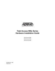
The ADTRAN MULTI-RATE Office Channel Unit Dataport<br />
with Digital Data Service Power (MULTI-RATE <strong>OCU</strong><br />
<strong>DP</strong>) unit is designed for use in the Northern Telecom DE-<br />
3/4/4E PCM channel bank, and provides access to<br />
Digital Data Service (DDS) or Basic Digital Service at all<br />
standard rates. It provides the interface between the<br />
pulse code modulation (PCM) bus of the T-carrier system<br />
and the 4-wire loop extending to the customer premises.<br />
Additionally, the unit may be used to power a midspan<br />
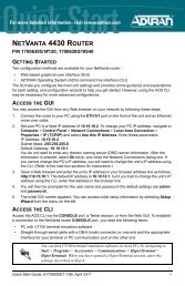
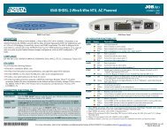
DDS repeater or DDS termination unit. Figure 1 is an<br />
illustration of the unit.<br />
Features<br />
Basic features of the MULTI-RATE <strong>OCU</strong> <strong>DP</strong>, part number<br />
1410005L2, include:<br />
• Subrate, 19.2 1 , 38.4, 56, and 64 kbps loop speeds,<br />
including Secondary Channel<br />
• Switched 56 (SW56) operating mode<br />
• Extended loop range to 45 dB loss at all rates 2<br />
• Loss of sealing current disconnect capability<br />
• Poor loop quality disconnect capability<br />
Section 61410005L2-5<br />
Issue 1, November 1996<br />
D4D14DJ1AA _ _<br />
Figure 1. ADTRAN MULTI-RATE <strong>OCU</strong> <strong>DP</strong><br />
• Hardware or software A/B signaling detection for<br />
Switched 56<br />
• Bantam jack test access<br />
• LED indicators for Loopback, Sealing Current, and<br />
Abnormal Station Code.<br />
The MULTI-RATE <strong>OCU</strong> <strong>DP</strong> occupies a single channel<br />
position in the Northern Telecom DE-3/4/4E channel<br />
bank and provides the interface between a DS-0 time<br />
slot of the T-carrier datastream and the 4-wire metallic<br />
loop extending to a midspan DDS repeater or the<br />
customer premises. A customer-provided DSU/CSU<br />
terminates the 4-wire loop; a DDS termination unit may<br />
also reside on the customer’s premises to provide<br />
loopback and test capability from the central office or<br />
remote test system. The MULTI-RATE <strong>OCU</strong> <strong>DP</strong> may<br />
interoperate over the carrier system with another <strong>OCU</strong><br />
<strong>DP</strong>, DS0 <strong>DP</strong>, DS-0 cross-connect system, or switch, and<br />
may be located in an end office, hub office, intermediate<br />
office, or remote digital terminal system.<br />
61410.005L2-5A<br />
Section 61410005L2-5, Issue 1<br />
ADTRAN 1<br />
Tx<br />
Rx<br />
<strong>OCU</strong> <strong>DP</strong><br />
1410005L2<br />
OUT IN<br />
SC<br />
64<br />
56<br />
38.4<br />
19.2<br />
9.6<br />
4.8<br />
2.4<br />
SW56<br />
<strong>OCU</strong> LB<br />
CHAN LB<br />
NO SX<br />
ASC<br />
SW2<br />
SW1<br />
1 2 3 4 5 6<br />
AB JUMPER
The MULTI-RATE <strong>OCU</strong> <strong>DP</strong> can be used as a replacement<br />
for the Northern Telecom <strong>OCU</strong> <strong>DP</strong> 684C.<br />
2. INSTALLATION<br />
After unpacking the unit, immediately inspect it for<br />
possible shipping damage. If damage is discovered, file<br />
a claim immediately with the carrier, then contact<br />
ADTRAN Customer Service, RMA; see subsection 4.<br />
The MULTI-RATE <strong>OCU</strong> <strong>DP</strong> plugs directly into a Northern<br />
Telecom DE-3/4/4E channel bank and requires no special<br />
wiring or connections.<br />
Optioning<br />
The ADTRAN MULTI-RATE <strong>OCU</strong> <strong>DP</strong> is equipped with<br />
two dual in-line package (DIP) switches, a jumper, and<br />
a slide switch. See Figure 2, Table A, and Table B to<br />
provision the unit.<br />
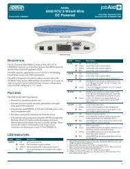
<strong>Rate</strong> Selection<br />
See Figure 1 for the<br />
location of SW1 to set<br />
the data rate of the unit.<br />
Select the desired rate<br />
by turning the appropriate<br />
switch to the In<br />
position. Only one rate<br />
should be selected.<br />
For Secondary<br />
Channel operation,<br />
select the SC switch<br />
and the appropriate<br />
rate switch by turning<br />
both switches to the In<br />
position. In SW56 or<br />
64 modes of operation,<br />
SC must not be<br />
selected.<br />
Figure 2. <strong>Rate</strong> Selection<br />
Switches<br />
AB Jumper<br />
See Figure 1 for the location of the AB jumper. The AB<br />
jumper must be positioned in accordance with the type<br />
of backplane used in the channel bank. See Table A for<br />
appropriate jumper positions.<br />
Table A. AB Jumper<br />
Function<br />
Pins/Position<br />
Select clock and power source<br />
for the following:<br />
DE-4 J7265AA-1 backplanes<br />
DE-3 J7204AA-1 backplanes<br />
DE-3 J7204AB-1 backplanes<br />
DE-4E J7265AC-1 backplanes<br />
DE-1000 J7510C-1 backplanes<br />
OUTIN<br />
1 2 3 4 5 6 7 8 9<br />
P1, P2, P3<br />
NOTE: DE-3/4 channel banks must be modified to<br />
accept data units before the MULTI-RATE <strong>OCU</strong><br />
<strong>DP</strong> can be installed.<br />
A<br />
A<br />
A<br />
B<br />
B<br />
SC<br />
64<br />
56<br />
38.4<br />
19.2<br />
9.6<br />
4.8<br />
2.4<br />
SW56<br />
SW2 Optioning<br />
Table B provides provisioning information about the options<br />
located on SW2. See Figure 1 for the location of SW2.<br />
Table B. Option Switch Settings<br />
Function<br />
Switch/Description<br />
Error Correction SW2-1 (ERROR CORRECTION)<br />
On-Enables Error Correction<br />
Off-Disables Error Correction<br />
Zero Code SW2-2 (ZERO CODE SUPPRESSION)<br />
Suppression On-Enables Zero Code Suppression<br />
Off-Disables Zero Code Suppression<br />
Latching SW2-3 (LATCHING LOOPBACK ENABLE)<br />
Loopback On-Responds to latching loopback<br />
sequences<br />
Off-Ignores latching loopback sequences<br />
AB Signaling<br />
Quality Monitor<br />
Extended<br />
Transmit Range<br />
SW2-4 (AB SIGNALING)<br />
On-Enables hardware A/B bit detection<br />
Off-Enables in-band A/B bit detection<br />
SW2-5 (QUALITY MONITOR)<br />
On-Enables AutoDisconnect feature<br />
Off-Disables AutoDisconnect feature<br />
SW2-6 (Extended Transmit Range)<br />
On-Enables ETR<br />
Off-Disables ETR<br />
Error Correction<br />
When error correction is enabled, the MULTI-RATE<br />
<strong>OCU</strong> <strong>DP</strong> provides an error-detection and correction<br />
capability that maintains data integrity across the carrier<br />
facility. For subrate and 19.2 kbps rates, error correction<br />
and data transmission can be accomplished over a<br />
single DS-0 time slot. For rates of 38.4, 56, and 64 kbps,<br />
error correction requires one DS-0 time slot for data<br />
transmission and an additional DS-0 time slot for the<br />
error-correcting parity byte. The parity byte resides in<br />
the DS-0 time slot adjacent to and immediately following<br />
the DS-0 time slot occupied by the data. For this reason,<br />
the physical slot following the <strong>OCU</strong> <strong>DP</strong> must remain<br />
vacant. For rates of 38.4 kbps and above, the MULTI-<br />
RATE <strong>OCU</strong> <strong>DP</strong> optioned for error correction must not be<br />
placed in channel bank slot 24.<br />
Zero Code Suppression<br />
When zero code suppression is enabled, the MULTI-<br />
RATE <strong>OCU</strong> <strong>DP</strong> prevents a network byte consisting of all<br />
zeros from entering the T-carrier datastream. On<br />
alternate mark inversion (AMI) facilities, this function is<br />
necessary to maintain the pulse density required for<br />
synchronization. B8ZS-carrier facilities that<br />
accommodate 64 kbps Clear Channel operation do not<br />
require the zero code suppression function, and it is<br />
automatically disabled when the 64 kbps rate has been<br />
selected.<br />
2 ADTRAN Section 61410005L2-5, Issue 1 61410.005L2-5A
Latching Loopback<br />
When latching loopback is enabled, the <strong>Multi</strong>-<strong>Rate</strong><br />
<strong>OCU</strong> <strong>DP</strong> responds to <strong>OCU</strong> and CSU latching loopback<br />
sequences appropriately. The <strong>OCU</strong> LB and CSU LB<br />
indicators turn On following appropriate loopback<br />
sequence.<br />
AB Signaling<br />
When AB Signaling is enabled, the MULTI-RATE <strong>OCU</strong><br />
<strong>DP</strong> determines the state of the A and B signaling bits<br />
required for Switched 56 operation from the signals<br />
present on the backplane of the channel bank. This<br />
method assumes that tandems and cross-connects<br />
between the MULTI-RATE <strong>OCU</strong> <strong>DP</strong> and the switch<br />
have maintained the signaling bit positions through twostate<br />
or four-state optioning. When AB Signaling is<br />
disabled, the MULTI-RATE <strong>OCU</strong> <strong>DP</strong> derives signaling<br />
bits from the incoming data of the DS-0 time slot.<br />
This switch has no effect if the SW56 rate<br />
option is not enabled on SW1.<br />
Quality Monitor<br />
When Quality Monitor is enabled, the MULTI-RATE<br />
<strong>OCU</strong> <strong>DP</strong> monitors the incoming 4-wire loop data for the<br />
presence of severe bit errors. In the presence of a<br />
circuit disturbance, the MULTI-RATE <strong>OCU</strong> <strong>DP</strong> blocks<br />
the transmission of errored data into the network by<br />
substituting abnormal station code (ASC) bytes; upon<br />
clearing of the troubled condition, the MULTI-RATE<br />
<strong>OCU</strong> <strong>DP</strong> automatically restores data transmission. In<br />
multipoint systems, this feature permits the remaining<br />
branches to operate should one branch become<br />
corrupted. The ASC indicator turns On upon blocking of<br />
data; see Table C.<br />
Extended Transmit Range<br />
When Extended Transmit Range is enabled, the <strong>OCU</strong><br />
<strong>DP</strong> will automatically increase the transmitter output<br />
level if the received signal level has been attenuated by<br />
more than 34dB. The increase in output level provides<br />
approximately 6dB of boost to the customer equipment,<br />
aiding in signal recovery for marginal, extended range<br />
circuits.<br />
Table C. Indicators<br />
Indicator Description<br />
<strong>OCU</strong> LB<br />
Turns On upon <strong>OCU</strong> loopback<br />
activation<br />
CHAN LB<br />
Turns On upon CSU loopback<br />
activation<br />
NO SX<br />
Turns On in the absence of loop<br />
sealing current<br />
Turns On for unterminated circuit<br />
ASC<br />
and upon Quality Monitor autodisconnect;<br />
transmits Abnormal<br />
Station Code to network<br />
3. TESTING<br />
The ADTRAN MULTI-RATE <strong>OCU</strong> <strong>DP</strong> may be tested<br />
from a remote test system or through the faceplate<br />
bantam jacks using a TPI 108/109RT or functionally<br />
equivalent test set. The MULTI-RATE <strong>OCU</strong> <strong>DP</strong> responds<br />
to latching and alternating sequences of <strong>OCU</strong> and CSU<br />
loopback codes at all rates except 64 kbps.<br />
If 64 kbps is selected and the latching loopback<br />
option is enabled, the unit only responds to<br />
latching loopback sequences; alternating<br />
sequences are not valid at this rate.<br />
Loopbacks<br />
An <strong>OCU</strong> loopback causes a loopback to the network at<br />
the point in the MULTI-RATE <strong>OCU</strong> <strong>DP</strong> closest to the 4wire<br />
loop. The MULTI-RATE <strong>OCU</strong> <strong>DP</strong> responds to the<br />
CSU loopback sequence by reversing the sealing current<br />
direction on the 4-wire loop. Latching loopbacks permit<br />
a higher level of data pattern sensitivity testing than is<br />
afforded by the alternating loopback. The latching and<br />
alternating loopback sequences are defined in Tables D<br />
and E.<br />
4. WARRANTY AND CUSTOMER SERVICE<br />
ADTRAN will replace or repair this product within ten<br />
years from the date of shipment, if the product does not<br />
meet its published specifications or if it fails while in<br />
service. For detailed warranty, repair, and return<br />
information, refer to the ADTRAN Equipment Warranty<br />
and Return Policy and Procedure.<br />
Return Material Authorization (RMA) is required prior to<br />
returning equipment to ADTRAN. ADTRAN does not<br />
recommend that repairs be performed in the field.<br />
For service, RMA requests, or further information, contact<br />
one of the following numbers:<br />
ADTRAN Customer Service:<br />
RMA (Repair Service) (205) 971-8722<br />
Technical Support (Post-Sales) (800) 726-8663<br />
Applications Engineering<br />
(Pre-Sales Support and Inquiries) (800) 615-1176<br />
Sales (800) 827-0807<br />
Repair and Return Address:<br />
ADTRAN, Inc.<br />
Customer Service Department<br />
901 Explorer Boulevard<br />
Huntsville, Alabama 35806-2807<br />
61410.005L2-5A Section 61410005L2-5, Issue 1<br />
ADTRAN 3
Function<br />
Clear existing<br />
loopbacks<br />
Identify device<br />
to be looped<br />
Prepare<br />
to loop;<br />
send MAP<br />
code after<br />
30 bytes<br />
Activate<br />
loopback<br />
Table D. Latching Loopback Activation<br />
Sequence (in order)<br />
Byte Code<br />
Transition in<br />
progress (TIP)<br />
*0111010<br />
Loopback select<br />
code (LSC)<br />
*1010101 - <strong>OCU</strong><br />
*0110001 - CSU<br />
*1000001 - NI<br />
Loopback<br />
Enable (LBE)<br />
*1010110<br />
Far-End Voice<br />
(FEV)<br />
*1011010<br />
# of Received<br />
Bytes<br />
Minimum of 35<br />
TIP bytes<br />
Minimum of 35<br />
LSC bytes<br />
Minimum of 100<br />
LBE bytes<br />
Minimum of 32<br />
FEV bytes<br />
Minimum of 35 TIP bytes required to disable established<br />
latching loopback.<br />
* - Don't Care bit<br />
Table E. Alternating Loopback Activation<br />
Sequence (in order)<br />
Function<br />
Activate loopback<br />
Maintain loopback and<br />
test for bit errors<br />
Clear loopback<br />
* - Don't Care bit D - data bit<br />
Received Bytes<br />
Four consecutive bytes of<br />
specified loopback code<br />
*0101010 - <strong>OCU</strong><br />
*0101000 - CSU<br />
*0101100 - DSU<br />
Data byte alternating with<br />
loopback code<br />
example:<br />
*DDDDDD1/*0101010<br />
Four consecutive data bytes<br />
4 ADTRAN Section 61410005L2-5, Issue 1 61410.005L2-5A