Create successful ePaper yourself
Turn your PDF publications into a flip-book with our unique Google optimized e-Paper software.
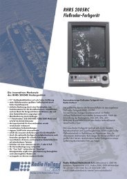
<strong>RIVER</strong> <strong>RADAR</strong><br />
RHRS-2005RCTFT<br />
SAIT-RADIO HOLLAND MARINE B.V.<br />
Eekhoutstraat 2, 3087 AB Rotterdam - P.O. Box 5068, 3008 AB Rotterdam, Holland<br />
Tel: +31 (0)10-4283344, Fax: +31 (0)10-4281498
( HIMA)<br />
All rights reserved.<br />
Printed in Japan<br />
PUB. No. OME-34881<br />
RHRS-2005RCTFT<br />
FIRST EDITION : AUG. 2001
SAFETY INSTRUCTIONS<br />
Radio Frequency Radiation Hazard<br />
WARNING<br />
The radar antenna emits electromagnetic radio frequency (RF) energy which can be<br />
harmful, particularly to your eyes. Never look directly into the antenna aperture from a<br />
close distance while the radar is in operation or expose yourself to the transmitting<br />
antenna at a close distance.<br />
Distances at which RF radiation levels of 100 and 10 W/m 2 exist are given in the table<br />
below.<br />
Note: If the antenna unit is installed at a close distance in front of the wheel house,<br />
your administration may require halt of transmission within a certain sector of antenna<br />
revolution. This is possible. Ask your dealer to provide this feature.<br />
Radiator<br />
type<br />
Distance to<br />
100 W/m 2<br />
point<br />
XN-14A 0.9 m<br />
Nill<br />
XN-22AF<br />
Distance to<br />
10 W/m 2<br />
point<br />
1.0 m<br />
XN-20AR 0.1 m 1.4 m<br />
RF power density<br />
on antenna aperture<br />
78 W/m 2<br />
83 W/m 2<br />
118 W/m 2<br />
� �
WARNING<br />
ELECTRICAL SHOCK HAZARD<br />
Do not open the equipment.<br />
Only qualified personnel<br />
should work inside the<br />
equipment.<br />
Turn off the radar power<br />
switch before servicing the<br />
antenna unit. Post a warning<br />
sign near the switch<br />
indicating it should not be<br />
turned on while the antenna<br />
unit is being serviced.<br />
Prevent the potential risk of<br />
being struck by the rotating<br />
antenna and exposure to<br />
RF radiation hazard.<br />
Wear a safety belt and hard<br />
hat when working on the<br />
antenna unit.<br />
Serious injury or death can<br />
result if someone falls from<br />
the radar antenna mast.<br />
Before turning on the radar, make sure<br />
that there is no one near the antenna<br />
unit.<br />
Serious injury or even death may result if<br />
a rotating antenna strikes someone<br />
standing nearby.<br />
Do not disassemble or modify the<br />
equipment.<br />
Fire, electrical shock or serious injury can<br />
result.<br />
Turn off the power immediately if water<br />
leaks into the equipment or the equipment<br />
is emitting smoke or fire.<br />
Continued use of the equipment can cause<br />
fire or electrical shock.<br />
Use the proper fuse.<br />
WARNING<br />
Fuse rating is shown on the equipment.<br />
Use of a wrong fuse can result in equipment<br />
damage.<br />
Keep heater away from equipment.<br />
Heat can alter equipment shape and melt<br />
the power cord, which can cause fire or<br />
electrical shock.<br />
Do not place liquid-filled containers on<br />
the top of the equipment.<br />
Fire or electrical shock can result if a liquid<br />
spills into the equipment.<br />
Do not operate the equipment with wet<br />
hands.<br />
Electrical shock can result.<br />
CAUTION<br />
A warning label is attached to the<br />
display unit and processor unit.<br />
Do not remove the label.<br />
If the label is missing or illegible,<br />
contact place of purchase about<br />
replacement.<br />
WARNING<br />
To avoid electrical shock, do not<br />
remove cover. No user-serviceable<br />
parts inside.<br />
�� �
TABLE OF CONTENTS<br />
FOREWORD..........................................iv<br />
SYSTEM CONFIGURATION ..................v<br />
SPECIFICATIONS ............................SP-1<br />
1. OPERATION...................................1-1<br />
1.1 Turning on the Power ....................... 1-1<br />
1.2 Transmitter ON................................. 1-2<br />
1.3 Control Head .................................... 1-3<br />
1.4 Screen Brilliance .............................. 1-4<br />
1.5 Icon-based Operation Overview....... 1-4<br />
1.6 Tuning the Receiver ......................... 1-4<br />
1.7 On-screen Legends and Markers..... 1-6<br />
1.8 Selecting the Range Scale ............ 1-7<br />
1.9 Selecting the Pulselength .............. 1-7<br />
1.10 Adjusting the Sensitivity ................... 1-7<br />
1.11 Suppressing Sea Clutter .................. 1-8<br />
1.12 Suppressing Precipitation Clutter..... 1-8<br />
1.13 FTC (Fast Time Constant)................ 1-8<br />
1.14 Interference Rejector........................ 1-9<br />
1.15 Echo Stretch ..................................... 1-9<br />
1.16 Noise Rejector.................................. 1-9<br />
1.17 Echo Averaging .............................. 1-10<br />
1.18 Contrast.......................................... 1-10<br />
1.19 Measuring the Range ..................... 1-10<br />
1.20 Measuring the Bearing ................... 1-11<br />
1.21 Off-Centering.................................. 1-12<br />
1.22 Menu Operation.............................. 1-12<br />
1.23 Cursor Data Format........................ 1-13<br />
1.24 Target Trails.................................... 1-13<br />
1.25 Markers........................................... 1-14<br />
1.26 Background Color........................... 1-15<br />
1.27 Echo Color...................................... 1-15<br />
1.28 Panel Dimmer................................. 1-15<br />
1.29 Adjusting Brilliance of Screen Data 1-15<br />
iii<br />
1.30 Programming Sets of<br />
Brilliance and Echo .........................1-16<br />
1.31 Turning On/Off Heading, Speed,<br />
Position, Depth, Time......................1-17<br />
1.32 ROT, Rudder, Autopilot Graphs ......1-18<br />
1.33 Nav Lines ........................................1-21<br />
1.34 Radar Map ......................................1-22<br />
1.35 Alarms, Error Messages .................1-24<br />
2. <strong>RADAR</strong> OBSERVATION ............... 2-1<br />
2.1 General .............................................2-1<br />
2.2 False Echoes ....................................2-2<br />
3. MAINTENANCE............................. 3-1<br />
3.1 Replacement of Fuse........................3-1<br />
3.2 Periodic Maintenance Schedule .......3-2<br />
3.3 Life Expectancy of Major Parts .........3-2<br />
4. TROUBLESHOOTING................... 4-1<br />
4.1 Easy Troubleshooting .......................4-1<br />
4.2 Advanced-level<br />
Troubleshooting ................................4-2<br />
4.3 Diagnostic Test..................................4-4<br />
5. PARTS LIST .................................. 5-1<br />
5.1 Processor Unit RPU-012 ..................5-1<br />
5.2 Display Unit RDP-140.......................5-2<br />
5.3 Control Unit RCU-013.......................5-4<br />
5.4 RF Unit RTR-071 ..............................5-4<br />
6. DIGITAL INTERFACE (IEC-61162-1)<br />
.............................................. 6-1<br />
MENU TREE ....................................MN-1<br />
INDEX .......................................... Index-1
FOREWORD<br />
A Word to the Owner of the<br />
RHRS-20005RCTFT Radar<br />
Thank you for purchasing the<br />
RHRS-20005RCTFT. It has been developed<br />
with the latest electronics and microcomputer<br />
technologies.<br />
Utilizing the 18.1-inch high resolution LCD<br />
screen, the RHRS-2005RCTFT has been<br />
designed to meet the Rhine River Radar<br />
requirements.<br />
Please carefully read the safety information<br />
and operating instructions set forth in this<br />
manual before attempting to operate the<br />
equipment and conduct any maintenance.<br />
Your radar set will perform to the utmost of its<br />
ability only if it is operated and maintained in<br />
accordance with the correct procedures.<br />
iv<br />
Features<br />
• Daylight-bright rasterscan 18.1-inch<br />
multi-color, high-resolution display.<br />
• New microprocessing technology with<br />
high-speed high-density gate array and<br />
software expertise.<br />
• Easy operation by combination of discrete<br />
keys, rotary controls, and menu operation,<br />
all logically arranged and configured.<br />
• Unique “icon-based” operation provides for<br />
quick adjustment of brilliance and<br />
echo-related functions.<br />
• Radar map function
���������������������<br />
ANTENNA UNIT<br />
EPFS<br />
SPEED LOG<br />
ECHO<br />
SOUNDER<br />
MAGNETIC<br />
COMPASS<br />
RSB-0085 (28 rpm)<br />
RSB-0086 (36/42 rpm)<br />
IEC61162<br />
IEC61162<br />
IEC61162<br />
IEC61162<br />
PROCESSOR UNIT<br />
RPU-012<br />
INPUT<br />
24-32 VDC<br />
RECTIFIER<br />
RU-1746B<br />
TRANSFORMER<br />
RU-1803<br />
Compass input is available either *1 or *2.<br />
When both are connected, the priority is *2>*1.<br />
Program Number<br />
*1<br />
WARNING<br />
XN-14A<br />
XN-22AF<br />
XN-20AR<br />
CONTROL HEAD<br />
RCU-013<br />
SHIP'S MAINS<br />
115/230 VAC<br />
1 , 50/60 Hz<br />
SHIP'S MAINS<br />
440 VAC<br />
1 , 50/60 Hz<br />
Unit Category<br />
Antenna unit Exposed to the weather<br />
Processor unit Protected from the weather<br />
Display unit Protected from the weather<br />
Control unit Protected from the weather<br />
SPU: 0359163-01.08<br />
(See page 4-4 to confirm this on the screen.)<br />
*2<br />
DISPLAY UNIT<br />
RDP-140<br />
AD CONVERTER<br />
AD-100<br />
SUB DISPLAY<br />
UNIT (max. 2)<br />
RATE OF TURN<br />
SENSOR<br />
AUTOPILOT<br />
RUDDER<br />
HEADING<br />
SENSOR<br />
PG-1000<br />
GYROCOMPASS<br />
: OPTIONAL<br />
EQUIPMENT<br />
�� �
This page is intentionally left blank.<br />
�� �
��� ����������<br />
The example screens shown in this manual may not match the screens you see on your display.<br />
The screen you see depends on your system configuration and equipment settings.<br />
���� ���������������������<br />
WARNING<br />
Before turning on the radar, make sure<br />
that there is no one near the antenna<br />
unit.<br />
Serious injury or even death may result if<br />
a rotating antenna strikes someone<br />
standing nearby.<br />
The [POWER] switch is located on the control unit. Push it to switch on the radar system.<br />
Bearing scale and digital appears in approximately 15 seconds. The timer counts down one<br />
minute of warm-up time. During this period the magnetron, transmitter tube, is warmed for<br />
transmission. When the timer has reached 0:00, the indication ST-BY appears, indicating that<br />
the radar is ready to transmit pulses.<br />
POWER<br />
switch<br />
Control head<br />
HOURS IN USE and TX HOURS values shown at middle of the screen are the time counts in<br />
hours and tenths of hours the radar has been powered and transmitted, respectively.<br />
To turn off the radar, push it again.<br />
NOTICE<br />
The brilliance of the LCD is adjustable<br />
to match a wide variety of lighting<br />
conditions. However, its maximum<br />
setting may not be sufficiently bright<br />
to permit viewing of the display with<br />
polarized sunglasses.<br />
���
���� ���������������<br />
When the indication ST-BY appears on the<br />
screen, press the [STBY/XMIT] switch on the<br />
control head.<br />
The radar is initially set to previously used<br />
range and pulselength. Data brilliance and<br />
echo settings are as shown at the left bottom<br />
and right bottom on the display, respectively.<br />
The STBY/XMIT switch toggles the radar<br />
between standby and transmit status. The<br />
antenna stops in standby status and rotates<br />
in transmit status.<br />
������� The magnetron ages with time<br />
resulting in a reduction of output power. It is<br />
highly recommended that the radar be set to<br />
standby status when not used for an<br />
extended period of time.<br />
������� If the antenna does not rotate in the<br />
transmit mode, suspect that the Service<br />
Switch on the antenna housing is set in the<br />
OFF position.<br />
���<br />
������������<br />
Provided that the radar was once in use with<br />
the transmitter tube (magnetron) still warm,<br />
you can turn the radar into Transmit condition<br />
without standby. If the [POWER] switch has<br />
been turned off by mistake or the like and you<br />
wish to restart the radar promptly, turn on the<br />
[POWER] switch not later than 10 seconds<br />
after power-off.<br />
.<br />
Freeze-up Recovery<br />
Picture freeze-up and keyboard lock-up can<br />
occur unexpectedly on any digital<br />
rasterscan radars. This is mainly caused by<br />
heavy spike noise in the power line and can<br />
be noticed by carefully watching the nearly<br />
visible sweep line. If you suspect that the<br />
picture is not updated every scan of the<br />
antenna or no key entry is accepted<br />
notwithstanding the apparently normal<br />
pictures, do Quick Start below to restore<br />
normal operation.<br />
1. Turn off the Power Switch and within 10<br />
seconds turn it on again.<br />
2. Press the STBY/XMIT switch STBY/XMIT<br />
for transmit condition.
���� �������������<br />
EBL Control<br />
Turns EBL on/off;<br />
Rotates EBL.<br />
ON/OFF(PUSH)<br />
STBY<br />
XMIT<br />
STBY/XMIT Switch<br />
Transmits radar pulses;<br />
places radar in standby.<br />
BRILLIANCE Control<br />
Adjusts screen brilliance.<br />
SRH<br />
PULSE HL OFF<br />
RHRS-2005RC TFT<br />
EBL BRILL VRM<br />
NAV LINE RANGE<br />
NAV LINE Keys<br />
Turns nav line<br />
display on<br />
(moving with<br />
VRM, fix)/off.<br />
HL OFF Key<br />
Temporarily erases<br />
heading line.<br />
PULSE Key<br />
Selects pulselength.<br />
VRM Control<br />
Turns VRM on/off;<br />
adjusts radius of<br />
VRM.<br />
OFF CENTER Key<br />
Off centers display.<br />
ON/OFF(PUSH)<br />
OFF<br />
CENTER<br />
RANGE Keys<br />
Selects range.<br />
FUNC(PUSH)<br />
MARK<br />
ERASE<br />
LEVEL<br />
LEVEL Control<br />
Adjusts level of item selected;<br />
each pressing selects GAIN,<br />
A/C SEA or A/C RAIN.<br />
MENU Key<br />
Opens/closes menu.<br />
MENU<br />
ENTER<br />
ERASE Key<br />
Erases marks.<br />
MARK Key<br />
Discribes marks.<br />
Trackball<br />
Shifts cursor; selects<br />
items/options on menus.<br />
ENTER Key<br />
Concludes entry of selection.<br />
���
���� ������������������<br />
The [BRILL] control adjusts the entire screen<br />
brightness. Note that the optimum point of<br />
adjustment varies with ambient light<br />
conditions, especially between daytime and<br />
nighttime<br />
����� The LCD brilliance should be adjusted<br />
before adjusting the brilliance of individual<br />
functions such as Gain and Modes.<br />
���� ���������������������<br />
���������<br />
A unique feature of this radar is its icon-based<br />
operation. Using the trackball you select<br />
on-screen item to adjust and set desired option<br />
with the [ENTER] key and [LEVEL] control.<br />
Icon-based items are circumscribed and they<br />
appear at the bottom left and bottom right<br />
corners of the screen, as below.<br />
���<br />
DISP<br />
STD BRILL2<br />
EBL<br />
VRM<br />
NAV<br />
HL<br />
RINGS<br />
+<br />
OS-MK<br />
MARK<br />
DATA<br />
TRAIL<br />
PANEL<br />
BRILL<br />
ECHO<br />
COLOR<br />
BACK<br />
COLOR<br />
DISP<br />
STD ECHO2<br />
FTC OFF<br />
IR OFF<br />
ES OFF<br />
NR OFF<br />
EAV OFF<br />
CONTRAST1<br />
STD BRILL set (2) STD ECHO set (2)<br />
For example, to set the interference rejector do<br />
the following:<br />
1. Use the trackball to select IR (Interference<br />
Rejector) at the bottom right corner of the<br />
screen. The cursor changes to an arrow<br />
outside of the display area. IR and its frame<br />
appear in a different color (color depends<br />
on color assignment) to indicate the<br />
selection.<br />
2. Press the [ENTER] key to set option. Each<br />
pressing of the key changes the indication<br />
cyclically. For IR, the display shows IR1,<br />
IR2, IR3 or OFF with each pressing of the<br />
[ENTER] key.<br />
���� ��������������������<br />
������ ��������������������<br />
Do the following to find the best tuning point:<br />
1. Press the [MENU] key to open the menu.<br />
The menu appears at the bottom-left side<br />
of the display as below.<br />
������ �<br />
DATA > MARK<br />
GRAPH> MAP<br />
INITIALIZE<br />
2. Use the trackball to select INITIALIZE. The<br />
display changes as below.<br />
OTHERS ><br />
DATA ><br />
GRAPH> MAP<br />
����������<br />
TUNE<br />
INITIALIZE TEST<br />
MARK<br />
3. Use the trackball to select TUNE<br />
INITIALIZE and press the [ENTER] key.<br />
The menu is erased and tuning initialization<br />
starts; you can monitor the initialization by<br />
watching the tuning indicator at the bottom<br />
right corner.<br />
AUTO TUNE
������ ��������������<br />
Tuning method can be selected for automatic<br />
or manual with the icon-based item TUNE.<br />
The default method is “automatic.”<br />
1. Use the trackball to select AUTO TUNE at<br />
the bottom-right hand corner of the screen.<br />
2. Press the [ENTER] key to display AUTO<br />
TUNE or MANUAL TUNE as appropriate.<br />
������ �����������������<br />
The radar receiver is tuned automatically<br />
each time the power is turned on. The tuning<br />
indicator and the label AUTO TUNE appear at<br />
the bottom right corner of the screen.<br />
������ ��������������<br />
If you are not satisfied with the current tune<br />
setting, follow these steps to fine-tune the<br />
receiver:<br />
1. Set the tuning method to manual as<br />
described in paragraph 1.6.2.<br />
2. Use the trackball to place the arrow<br />
anywhere on the tuning indicator.<br />
3. Slowly adjust the [LEVEL] control on the<br />
control head and find the best tuning point,<br />
monitoring the display.<br />
MANUAL TUNE<br />
4. Make sure that the radar has been set to<br />
the best tuning point. This condition is<br />
where the tuning indicator lights to about<br />
80% of its total length. Note that the tuning<br />
indicator will never extend to full length.<br />
���
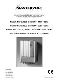
���� ������������������������������<br />
���<br />
Heading<br />
Speed source, speed<br />
Radar map symbol<br />
(name above)<br />
Bearing Scale<br />
Nav Line<br />
Heading Line<br />
Range Rings<br />
EBL<br />
Saves brilliance settings.<br />
Turns brilliance<br />
settings indications<br />
on/off.<br />
Selects brilliance<br />
set no. (1, 2, 3, 4).<br />
Turns range rings on/off.<br />
Turns own ship marker on/off.<br />
Turn radar map marks on/off.<br />
Brilliance Settings<br />
Note: (Short Pulse) or (Long Pulse)<br />
appears above pulselength on<br />
2, 4 and 8 km ranges.<br />
Range, Range<br />
Ring Interval<br />
Pulselength<br />
300<br />
200<br />
ROT<br />
SP RUDDER<br />
030 SPD TRIG 020 EPFS<br />
VIDEO HL AZI<br />
0.25/0.05km COMPASS<br />
COMPASS 123.9˚<br />
NAV SPD 12.3km/h<br />
PROHIBITED 330<br />
AREAS<br />
300<br />
270<br />
SAVE<br />
DISP<br />
STD BRILL2<br />
EBL<br />
VRM<br />
NAV<br />
HL<br />
RING<br />
+<br />
OS-MK<br />
MARK<br />
DATA<br />
TRAIL<br />
240<br />
PANEL<br />
BRILL<br />
ECHO<br />
COLOR<br />
210<br />
BACK EBL 123.4˚R<br />
COLOR NAV 0.16 km<br />
NAV line setting<br />
(distance from<br />
port side nav line<br />
to own ship)<br />
Missing Signal*<br />
100 ROT ALARM 000 ACK<br />
010<br />
000<br />
180<br />
100<br />
010<br />
Own Ship<br />
Symbol<br />
Stern Mark<br />
EBL Reading<br />
ROT alarm acknowledged<br />
Rate-of-Turn, Rudder,<br />
Autopilot Scales<br />
200<br />
020<br />
300˚<br />
030˚<br />
060<br />
090<br />
SAVE<br />
DISP<br />
STD ECHO2<br />
FTC OFF<br />
IR OFF<br />
ES OFF<br />
00:00 NR OFF<br />
TRUE 2SCAN EAV OFF<br />
TRAILS OFF CONTRAST1<br />
MANUAL TUNE<br />
150<br />
VRM 0.16 km<br />
NAV 0.16 km<br />
/min<br />
AUTO PILOT<br />
OS POSN 12˚34.567 N<br />
[DGPS] 123˚45.678 E<br />
030<br />
VRM reading<br />
+<br />
12˚34.567 N<br />
123˚45.678 E<br />
DEPTH 123.4 m<br />
16-MAY-2001<br />
23:59<br />
LOCAL<br />
120<br />
GAIN<br />
A/C SEA<br />
A/C RAIN<br />
NAV line setting<br />
(distance from<br />
starboard side nav<br />
line to own ship)<br />
* - Indication appears in red and alarm sounds when corresponding signal is lost.<br />
Position input, ship position<br />
Cursor position<br />
Depth<br />
Date<br />
Time, time format<br />
Range Marker (VRM)<br />
Target trails settings (from top)<br />
Time elapsed<br />
Trail reference (TRUE or REL)<br />
Trail time (2 scan, 15, 30 sec.,<br />
1, 3 min)<br />
Trail ON/OFF<br />
Saves echo settings.<br />
Turns echo settings<br />
display on/off.<br />
Selects brilliance set no.<br />
(1, 2, 3, 4).<br />
Echo settings<br />
Tuning method, tuning indicator<br />
GAIN setting<br />
A/C SEA setting<br />
A/C RAIN setting
���� �������������������� �<br />
������<br />
The display range scale is changed by pressing<br />
the [+] and [-] keys. The selected range scale<br />
and range ring interval are shown at the upper<br />
left corner of the screen. When a target of<br />
interest comes closer, reduce the range scale<br />
so that it appears in 50-90% of the display<br />
radius. The range scales are;<br />
0.25 - 0.5 - 0.8 - 1.2 - 1.6 – 2 – 4 – 8 – 16 –<br />
32 – 64 (km)<br />
���� �������������� �<br />
������������<br />
The pulselength may be selected for short,<br />
medium or long pulse on the ranges shown in<br />
table below. The pulselength in use appears<br />
at the top left-hand corner of the screen as<br />
SP (Short Pulse)/MP (Middle Pulse)/LP (Long<br />
Pulse) with the pulse symbol ( ). To<br />
change the pulselength, press the [PULSE]<br />
key.<br />
�<br />
Range Available<br />
pulselength<br />
2 km SP, MP<br />
4 km MP, LP<br />
8 km MP, LP<br />
����� ��������������������������<br />
The GAIN control (icon) is used to adjust the<br />
sensitivity of the receiver, and thus the<br />
intensity of echoes as they appear on the<br />
screen. It should be adjusted so that speckled<br />
background noise is just visible on the<br />
screen.<br />
Higher gain increases the echo intensity but<br />
reduces the ditections. Lower gain setting<br />
results in the loss of weak echoes and<br />
reduces detection range.<br />
1. Press the [FUNC] switch several times to<br />
select the GAIN indicator at the bottom right<br />
of the screen. Each pressing of the [FUNC]<br />
switch selects GAIN, A/C SEA or A/C RAIN.<br />
GAIN<br />
2. Use the [LEVEL] control to set the gain.<br />
����� The gain indicator may also be<br />
selected with the trackball.<br />
.<br />
� ��� �
1.11 Suppressing Sea Clutter<br />
In rough weather conditions returns from the<br />
water surface are received over several<br />
kilometers around own ship and mask close<br />
targets. This situation can be improved by<br />
properly adjusting the A/C SEA (Anti-Clutter<br />
Sea) control.<br />
A/C SEA control off A/C SEA control adjusted<br />
A common mistake is to over adjust the A/C<br />
SEA control so that the surface clutter is<br />
completely removed. By using maximum A/C<br />
SEA, you will see how dangerous this can be; a<br />
dark zone shown above is created near the<br />
center of the screen and close-in targets can be<br />
lost. This dark zone is even more dangerous if<br />
the gain has not been properly adjusted. Always<br />
leave a little surface clutter visible on the screen.<br />
If no surface clutter is observed (on a very calm<br />
water), turn off the A/C SEA.<br />
To adjust the A/C SEA;<br />
1. Press the [FUNC] switch several times to<br />
select the A/C SEA indicator. (The A/C SEA<br />
indicator may also be selected with the<br />
trackball.)<br />
1-8<br />
A/C SEA<br />
2. Use the [LEVEL] control to set level.<br />
For optimum target detection, you should<br />
leave speckles of the surface return slightly<br />
visible.<br />
The anti-clutter sea control is often referred to<br />
as STC (Sensitivity Time Control) which<br />
decreases the amplification of the receiver<br />
immediately after a radar pulse is transmitted,<br />
and progressively increases the sensitivity as<br />
the range increases. A/C SEA is effective up<br />
to about 4 km.<br />
1.12 Suppressing<br />
Precipitation Clutter<br />
In adverse weather conditions, clouds, rain or<br />
snow produce a lot of spray-like spurious<br />
echoes and impairs target detection on close<br />
range targets. This situation can be improved<br />
by adjusting the A/C RAIN (Ant-Clutter Rain)<br />
control.<br />
A/C RAIN control<br />
OFF<br />
A/C RAIN control<br />
adjusted<br />
The A/C RAIN control adjusts the receiver<br />
sensitivity as the A/C SEA control does but<br />
rather in a longer time period (longer range).<br />
To adjust the A/C RAIN;<br />
1. Press the [FUNC] switch several times to<br />
select the A/C RAIN indicator. (The A/C<br />
RAIN indicator may also be selected with<br />
the trackball.)<br />
A/C RAIN<br />
2. Use the [LEVEL] control to set level.<br />
1.13 FTC (Fast Time<br />
Constant)<br />
CAUTION<br />
Switch off FTC if objective is to receive<br />
radar beacon.<br />
If you fail to effectively suppress rain clutter with<br />
the A/C RAIN, use the FTC function. In adverse<br />
weather, clouds, rain or snow produce<br />
spray-like spurious echoes which impair target<br />
detection over a long distance. These echoes<br />
can be suppressed by turning on the FTC<br />
circuit. There are two FTC settings, FTC1 and<br />
FTC2, FTC2 provides increased rain clutter<br />
suppression effectively.
1. Use the trackball to select FTC at the<br />
bottom right of the screen.<br />
2. Press the [ENTER] key to select the FTC<br />
setting 1, 2 or OFF as appropriate.<br />
����� FTC2 may only be enabled with<br />
medium or long pulselength. FTC1 is for short<br />
pulselength.<br />
����� ����������������������<br />
Mutual radar interference may occur in the<br />
vicinity of another shipborne radar operating in<br />
the same frequency band (9 GHz for X-band). It<br />
is seen on the screen as a number of bright<br />
spikes either in irregular patterns or in the form<br />
of usually curved spoke-like dotted lines<br />
extending from the center to the edge of the<br />
picture. This type of interference can be<br />
reduced by activating the interference rejector<br />
circuit.<br />
The interference rejector is a kind of signal<br />
correlation circuit. It compares the received<br />
signals over successive transmissions and<br />
suppresses randomly occurring signals. There<br />
are three levels of interference rejection IR1,<br />
IR2 and IR3 depending on the number of<br />
correlations.<br />
To activate the interference rejector;<br />
1. Use the trackball to select IR at the bottom<br />
right of the screen.<br />
2. Press the [ENTER] key to select level of<br />
interference rejection desired. Switch off<br />
the interference rejector when no<br />
interference exists; otherwise weak targets<br />
may be lost.<br />
����� �������������<br />
On short and medium ranges such as 2, 4<br />
and 8 km scales, the same size targets get<br />
smaller on screen as they approach the own<br />
ship. This is due to the radiation pattern of the<br />
antenna. To enhance target video, use the<br />
echo stretch function.<br />
ES1: Enlarges close-range echoes in bearing<br />
directions.<br />
ES2: Like ES1 but further enlarges<br />
close-range echoes.<br />
To activate the echo stretch do the following:<br />
1. Use the trackball to select ES at the<br />
bottom right of the screen.<br />
2. Press the [ENTER] key to display Echo<br />
Stretch option 1, 2 or OFF as desired.<br />
����� ���������������<br />
The noise rejector suppresses white noise,<br />
which appears on the screen as many dots<br />
scattered randomly over the display.<br />
1. Select NR at the bottom right of the screen.<br />
2. Press the [ENTER] key to turn the noise<br />
rejector on or off as appropriate.<br />
����� Noise rejector is effective on ranges of<br />
4 km and higher.<br />
� ��� �
����� ���������������<br />
����� This function requires a compass<br />
signal and selecting of LOG or NAV on<br />
DATA on the HEADING, SPEED menu.<br />
The echo average feature effectively<br />
suppresses sea clutter. Echoes received from<br />
stable targets such as ships appear on the<br />
screen at almost the same position every<br />
rotation of the antenna. On the other hand,<br />
unstable echoes such as sea clutter or false<br />
echoes appear at random positions.<br />
To distinguish real target echoes from sea<br />
clutter, this radar performs scan-to-scan<br />
correlation. Correlation is made by storing<br />
and averaging echo signals over successive<br />
picture frames. If an echo is solid and stable,<br />
it is presented in its normal intensity. Sea<br />
clutter is averaged over successive scans<br />
resulting in the reduced brilliance, making it<br />
easier to discriminate real targets from sea<br />
clutter (false echoes).<br />
To properly use the echo average function, it<br />
is recommended to first suppress sea clutter<br />
with the A/C SEA control and then do the<br />
following:<br />
1. Use the trackball to select EAV at the<br />
bottom right-hand corner of the screen.<br />
2. Press the [ENTER] key until echo average<br />
option 1, 2, 3 or OFF as desired is<br />
highlighted. The larger the figure the<br />
greater the suppression of unstable echoes.<br />
Note however that echoes moving at high<br />
speed may be lost in the highest setting.<br />
(a) Echo average OFF (b) Echo average ON<br />
���� �<br />
�<br />
Echo averaging uses scan-to-scan signal<br />
correlation technique based on the true<br />
motion over the ground of each target. Thus,<br />
small stationary targets such as buoys will be<br />
shown while suppressing random echoes<br />
such as sea clutter. Echo average is not<br />
effective for picking up small targets running<br />
at high speeds.<br />
CAUTION<br />
Do not use the Echo Average feature<br />
under heavy pitching and rolling; loss of<br />
true targets can result.<br />
����� ���������<br />
Contrast is adjustable in three levels according<br />
to the radar video sampling level. Select the<br />
level so the picture shows up most clearly from<br />
the background.<br />
1. Select CONTRAST at the bottom right of<br />
the screen.<br />
2. Press the [ENTER] key to select contrast<br />
level desired; 1, 2 or 3.<br />
����� ��������������������<br />
������� �����������������������<br />
������������<br />
Use the fixed range rings to obtain a rough<br />
estimate of the range to a target. They are the<br />
concentric circles about own ship, or the sweep<br />
origin. The number of rings is automatically<br />
determined by the selected range scale and<br />
their interval is displayed at the upper-left<br />
position on the screen.<br />
To turn the range rings on/off;<br />
1. Select RINGS at the bottom left of the<br />
screen.<br />
2. Press the [ENTER] key to turn the rings on<br />
or off as appropriate.
1.19.2 Measuring range by the<br />
variable range marker<br />
Use the Variable Range Marker (VRM) for<br />
more accurate measurement of the range to<br />
a target. Two VRM are available, one is short<br />
dashed ring and the other is long dashed.<br />
You can control one at a time.<br />
1. Press the [VRM] control to turn the VRM<br />
on.<br />
2. Turning the [VRM] control, align the active<br />
variable range marker with the inner edge<br />
of the target of interest and read its<br />
distance at the bottom right of the screen.<br />
Note: This radar can display two VRMs by<br />
turning on 2EBL•VRM on the MARK menu. In<br />
this case successive presses of the VRM<br />
control toggles the active VRM between No. 1<br />
and No. 2 and activated VRM readout is<br />
identified by >.....
1.20.1 Offsetting the origin of the<br />
EBL1<br />
The origin of the EBL1 can be placed anywhere<br />
with the trackball to enable measurement of<br />
range and bearing between any targets. This<br />
function is also useful for assessment of the<br />
potential risk of collision.<br />
1. Press the [EBL] control to display the<br />
EBL1.<br />
2. Use the trackball to place the cursor where<br />
desired.<br />
3. Press the [EBL] control while holding the<br />
[HL OFF] key down, and the origin of the<br />
EBL1 shifts to the cursor position.<br />
4. See the range and bearing indications for<br />
range and bearing to the target.<br />
1-12<br />
+<br />
+<br />
EBL2 is always fixed<br />
at OS position whether<br />
OS is centered or off-centered.<br />
Range<br />
Marker<br />
EBL origin<br />
To cancel the offset EBL, press the [EBL]<br />
control while pressing and holding down the [HL<br />
OFF] key.<br />
1.21 Off-Centering<br />
Own ship position, or sweep origin, can be<br />
displaced to expand the view field without<br />
switching to a larger range scale. The sweep<br />
origin is off-centered 33% in the stern<br />
direction (fixed), on any range.<br />
The number of range rings increases keeping<br />
the original range intervals unchanged.<br />
To off-center the radar picture do the<br />
following:<br />
1. Press the [OFF CENTER] key.<br />
2. To cancel off-centering, press the [OFF<br />
CENTER] key again.<br />
1.22 Menu Operation<br />
Less-often used functions are contained in the<br />
menu. This section shows you how to select<br />
items and options from the menu.<br />
1. Press the [MENU] key to open the menu.<br />
The menu appears at the bottom left-hand<br />
corner of the display as below. “>” indicates<br />
a menu has sub menus.<br />
������ �<br />
DATA > MARK<br />
GRAPH> MAP<br />
INITIALIZE<br />
2. Use the trackball to select a menu. For<br />
example, select MARK. Selected menu’s<br />
options appear.<br />
������ ��<br />
�<br />
DATA > ����<br />
GRAPH><br />
INITIALIZE<br />
CURSOR&EBL<br />
REF MODE<br />
TRUE /REL<br />
MAP<br />
2EBL·VRM<br />
OFF/ON<br />
STERN MARK<br />
OFF/ON<br />
Menu items (current settings are highlighted)<br />
3. Use the trackball to select menu item.<br />
4. Press the [ENTER] key to select option<br />
desired. Current selection is highlighted.<br />
5. Press the [MENU] key to close the menu.<br />
Note: A selected menu will close<br />
automatically after 30 seconds.
����� �������������������<br />
Cursor position can be displayed in range and<br />
bearing from own ship, X and Y coordinates<br />
from own ship and position in latitude and<br />
longitude from own ship.<br />
1. Use the trackball to place the arrow inside<br />
the + mark at the upper right of the<br />
screen.<br />
2. Press the [ENTER] key to select cursor<br />
data format. Each pressing of the key<br />
changes the cursor data format in the<br />
sequence shown below. Position data and<br />
compass data are required to display<br />
latitude and longitude position.<br />
+ X 6.200 km<br />
+ Y 11.15 km<br />
12.75 km<br />
029.1˚R<br />
Range, bearing X, Y coordinates<br />
from own ship from own ship<br />
+ 35.45˚N<br />
135.21˚E<br />
Latitude, longitude position<br />
from own ship*<br />
*L/L data and compass data are required.<br />
(If no compass data, L/L position display is skipped.)<br />
����� ��������������<br />
It is possible to display the trails of targets in<br />
the form of synthetic afterglow. This is useful<br />
for monitoring targets’ movements.<br />
����� Whenever turning the radar on, the<br />
echo trail settings are as follows;<br />
Presentation: Relative<br />
Trail time: 2 SCAN<br />
Trail OFF<br />
������� ������������������������<br />
You may display target trails in true or relative<br />
motion. Relative trails are shown relative to<br />
own ship; stationary targets will also have<br />
trails as OS moves. True motion trails require<br />
a compass signal, and speed. The spec may<br />
be LOG or NAV on the HEADING, SPEED<br />
menu. True motion trails present target ship<br />
movements in accordance with their<br />
over-the-ground speeds and courses.<br />
(a) True target trails - no smearing<br />
of stationary targets<br />
(b) Relative target trails - all targets<br />
moving relative to own ship<br />
1. Use the trackball to select TRUE (or REL,<br />
whichever is displayed) at the bottom right<br />
of the screen.<br />
2. Press the [ENTER] key to select TRUE or<br />
REL as appropriate.<br />
������� ���������������������������� �<br />
��������������<br />
1. Use the trackball to select TRAILS OFF at<br />
the right of the screen.<br />
2. Press the [ENTER] key to display TRAILS<br />
ON.<br />
3. Use the trackball to select the trail time icon<br />
2 SCAN, 15 SEC, 30 SEC, 1 MIN or 3 MIN<br />
option.<br />
4. Press the [ENTER] key to select desired<br />
trail time.<br />
� ���� �
������� �����������������������<br />
Operate the trackball to place the arrow on<br />
TRAIL at the bottom left and press the [ENTER]<br />
key to change the trail colors. Each pressing<br />
the [ENTER] key changes the color sequence<br />
as shown below.<br />
Echo<br />
color<br />
Trail color<br />
Background<br />
color is black<br />
Background color is<br />
blue<br />
Yellow Blue ↔ yellow Green ↔ yellow<br />
Green Yellow ↔ green White ↔ green<br />
White Blue ↔ white Blue ↔ white<br />
����� ��������<br />
������� �������������<br />
The heading line indicates the ship's heading.<br />
It is a line from the own ship position to the<br />
outer edge of the radar display area and<br />
appears at zero degrees on the bearing<br />
scale.<br />
���������������������������������<br />
If a target is mashed by the heading line,<br />
press and hold the [HL OFF] key to erase the<br />
line. The stern mark and own ship marker are<br />
also erased. The heading line reappears<br />
when the key is released.<br />
������� �����������<br />
The stern mark (a dot-and-dash line) appears<br />
opposite to the heading line. This mark can<br />
be turned on/off with STERN MK on the<br />
OTHERS menu.<br />
���� �<br />
�<br />
������� ����������������<br />
When the appropriate data is input, the own<br />
ship marker, which requires input of own ship<br />
data, is shown on the screen as ( ) by<br />
selecting OS-MK indicator at bottom left. The<br />
symbol is scaled to indicate the length and<br />
width of the vessel. If the largest dimension of<br />
the symbol gets smaller than 3 mm, the<br />
symbol will disappear. The own ship marker’s<br />
dimensions are set during installation. For<br />
details, contact your dealer.<br />
If the own ship marker is turned on, it can be<br />
erased from the screen as follows:<br />
1. Select OS-MK at the bottom.<br />
2. Press the [ENTER] key to turn the mark off.<br />
3. To turn it on again, repeat this procedure.<br />
����� You can temporarily erase this marker<br />
by pressing the [HL OFF] key.<br />
������� ������������� �<br />
You can define the shapes of barges (max. 10)<br />
which are transported by own ship as below:<br />
1. Operate the trackball to place the arrow on<br />
the OS-MK at the bottom left of the screen.<br />
2. Press the [ENTER] key to turn on the own<br />
ship mark, and the OS-MK level indicator<br />
appears.<br />
3. Operate the trackball to place the arrow on<br />
MARK at the bottom left of the screen. A<br />
(circumscribed) radar map symbol appears<br />
at the top left corner.<br />
4. Use the trackball to select the radar map<br />
symbol at the top left corner.<br />
������<br />
�����<br />
������<br />
�����<br />
X<br />
--<br />
����������� �������� ������ ����<br />
����� ���� ���� ����<br />
����� The triangle mark appears with the<br />
[LEVEL] control in the fully counterclockwise<br />
position.<br />
--
5. Turn the [LEVEL] control clockwise to<br />
select a desired barge number.<br />
6. Draw the barge shape as below:<br />
a) Using the trackball, select a barge and<br />
press the [MARK] key. The X·Y<br />
coordinates appear.<br />
X 73<br />
Y 88<br />
b) Drag the arrow to bottom right corner of<br />
barge and press the [MARK] key.<br />
7. Repeat steps 5 to 7 to enter other barges.<br />
8. Selecting the barge by turning [LEVEL]<br />
control as in step 5 and press the [ENTER]<br />
to retain the barge symbols.<br />
1.26 Background Color<br />
You may select the color for the background,<br />
display area and alphanumerics as follows:<br />
1. Use the trackball to select BACK COLOR<br />
at the bottom left.<br />
2. Press the [ENTER] key to select a desired<br />
color group. Each pressing of the [ENTER]<br />
key selects the color group as below:<br />
Item 1 2 3 4 5<br />
Background<br />
BLK BLK BLK BLU L-BLU<br />
Display<br />
Area<br />
Char.<br />
Markers<br />
BLK BLK BLU BLU L-BLU<br />
GRN RED GRN WHT WHT<br />
1.27 Echo Color<br />
Echoes may be displayed in yellow, green or<br />
white as follows:<br />
1. Select ECHO COLOR at the bottom left of<br />
the display.<br />
2. Press the [ENTER] key.<br />
1.28 Panel Dimmer<br />
To adjust illumination of the control head, do as<br />
follows:<br />
1. Select PANEL BRILL at the bottom left of<br />
the display.<br />
2. Press the [ENTER] key several times until<br />
a required intensity is reached within four<br />
levels.<br />
1.29 Adjusting Brilliance of<br />
Screen Data<br />
You can adjust the brilliance of marks and text<br />
on the screen. Items which can be adjusted are<br />
displayed at the bottom left as below:<br />
1. Using the trackball, place the arrow on the<br />
indicator of the item you want to adjust.<br />
DISP<br />
STD BRILL2<br />
EBL<br />
VRM<br />
NAV<br />
HL<br />
RING<br />
+<br />
OS-MK<br />
MARK<br />
DATA<br />
TRAIL<br />
PANEL<br />
BRILL<br />
ECHO<br />
COLOR<br />
BACK<br />
COLOR<br />
Indicator<br />
2. Adjust the [LEVEL] control to set brilliance.<br />
Note: To save the brilliance adjustment, see<br />
section 1.31.<br />
.<br />
1-15
����� �������������������� �<br />
������������������������������<br />
Suppose you have been navigating along a<br />
bank for hours and now you are approaching<br />
a harbor, your final destination. You will have<br />
to adjust your radar to change from the<br />
settings for bank navigation to those for<br />
harbor approach. Every time your navigating<br />
environment or task changes, you must<br />
adjust the radar, which can be a nuisance in a<br />
busy situation. Instead of changing radar<br />
settings case by case, it is possible to preset<br />
optimum settings for often encountered<br />
situations.<br />
1. Select STD BRILL or STD ECHO at the left<br />
and right corners of the screen,<br />
respectively.<br />
DISP<br />
STD BRILL2<br />
EBL<br />
VRM<br />
NAV<br />
HL<br />
RINGS<br />
+<br />
OS-MK<br />
MARK<br />
DATA<br />
TRAIL<br />
PANEL<br />
BRILL<br />
ECHO<br />
COLOR<br />
BACK<br />
COLOR<br />
DISP<br />
STD ECHO2<br />
FTC OFF<br />
IR OFF<br />
ES OFF<br />
NR OFF<br />
EAV OFF<br />
CONTRAST1<br />
STD BRILL set (2) STD ECHO set (2)<br />
2. Press the [ENTER] key to display STD<br />
BRILL(STD ECHO) 2, 3 or 4, whichever set<br />
you want to adjust.<br />
����� STD BRILL1 and STD ECHO1 can<br />
be adjusted but their settings are restored<br />
once the power is turned off. Whenever the<br />
power is turned on the radar starts up with<br />
STD BRILL1 and STD ECHO1 settings.<br />
���� �<br />
�<br />
3. Select and adjust an item and adjust<br />
brilliance levels with the [LEVEL] control;<br />
select echo settings with the [ENTER] key.<br />
Note that brilliance items OS-MK, MARK<br />
(radar map) and RINGS color can be<br />
turned on or off, TRAIL can be selected as<br />
desired by placing the arrow on the option<br />
name.<br />
4. The indication SAVE appears above DISP.<br />
Select SAVE and press the [ENTER] key.<br />
5. Repeat steps 1 and 4 to set other items.<br />
If you do not need STD BRILL or STD ECHO<br />
settings you may delete one or both by<br />
selecting DISP and pressing the [ENTER] key.<br />
Repeat the procedure in above to redisplay.
����������������������������� �<br />
������������������������<br />
�����������<br />
The DATA menu allows you to turn heading,<br />
speed, position, depth, date and time on or<br />
off. Appropriate sensors are required to<br />
display data.<br />
1. Press the [MENU] key to display the menu.<br />
2. Select DATA> with trackball.<br />
3. Select appropriate sub-menu with trackball.<br />
4. Press the [ENTER] key to set option.<br />
5. Press the [MENU] key to close the menu.<br />
����� The figure in the adjacent column<br />
shows all data of sub menus and their<br />
options.<br />
������� ������������<br />
Speed is input through a speed log or EPFS<br />
(GPS or Loran C). “SPD” appears in red at<br />
the upper left to warn speed data is absent<br />
for 90. Be sure to select SPEED DATA OFF<br />
on the HEADING, SPEED menu when neither<br />
speed log nor EPFS is connected. Otherwise,<br />
the speed reading will be “***” and an error<br />
message appears (in red).<br />
������� �����������������<br />
With GPS input UTC time is displayed<br />
(provided it is turned on in the DATE, TIME<br />
menu). If you prefer the local time to UTC, do<br />
the following:<br />
1. Select the DATE TIME menu following the<br />
procedure above in this column.<br />
2. Select LOCAL TIME ADJ.<br />
3. Adjust the [LEVEL] control to display the<br />
time difference between local time and<br />
UTC. The setting range is –13:30 to<br />
+13:30.<br />
4. Select LOCAL TIME ADJ.<br />
OTHERS<br />
���� ��<br />
�<br />
GRAPH><br />
INITIALIZE<br />
HEADING<br />
DATA<br />
OFF /ON<br />
OTHERS<br />
���� ��<br />
�<br />
GRAPH><br />
INITIALIZE<br />
OWN SHIP<br />
POSN DATA<br />
OFF /ON<br />
OTHERS<br />
���� ��<br />
�<br />
GRAPH><br />
INITIALIZE<br />
DATE TIME<br />
OFF /UTC/<br />
LOCAL<br />
��������<br />
�����<br />
OS POSN<br />
DEPTH<br />
DATE<br />
TIME<br />
SPEED DATA<br />
OFF/km/h/<br />
kt<br />
HEADING SPEED sub menu<br />
HEADING<br />
SPEED<br />
�� �����<br />
�����<br />
DATE<br />
TIME<br />
DEPTH DATA<br />
OFF/m/ft/<br />
FA<br />
OS POSN sub menu<br />
HEADING<br />
SPEED<br />
OS POSN<br />
DEPTH<br />
�����<br />
����<br />
LOCAL TIME<br />
ADJ<br />
+00:00<br />
DATE TIME sub menu<br />
SPEED<br />
MODE<br />
NAV/LOG<br />
� ���� �
1.32 ROT, Rudder, Autopilot Graphs<br />
The ROT (Rate of Turn), RUDDER and AUTOPILOT graphs appear at the top of the display, and<br />
they may be turned on or off and adjusted on the GRAPH menu.<br />
1-18<br />
ROT Graph<br />
Rudder Graph<br />
ROT Graph<br />
Rudder Graph<br />
ROT<br />
RUDDER<br />
ROT<br />
RUDDER<br />
300<br />
030<br />
300<br />
030<br />
1.32.1 Graph Description<br />
ROT graph<br />
The ROT graph displays ship’s rate of turn<br />
(degrees/min), with a ROT signal from a ROT<br />
sensor. If the rate-of-turn indicator fails, he<br />
indication ROT ALARM appears at the top of<br />
the screen and the radar beeps intermittently.<br />
To acknowledge loss of ROT signal do the<br />
following:<br />
1. Use the trackball to select the indication<br />
ROT ALARM.<br />
2. Press the [ENTER] key to silence the alarm.<br />
The indication ROT ALARM ACK replaces<br />
ROT ALARM.<br />
200<br />
020<br />
200<br />
020<br />
100 000<br />
010<br />
000<br />
100 000<br />
010<br />
Autopilot ROT graph<br />
100<br />
010<br />
Non-followup autopilot<br />
000<br />
100<br />
010<br />
200<br />
020<br />
200<br />
020<br />
Autopilot RUDDER graph<br />
Followup autopilot<br />
Rudder graph<br />
300˚<br />
030˚<br />
300˚<br />
030˚<br />
/min<br />
AUTO PILOT<br />
/min<br />
FOLLOW<br />
UP<br />
The rudder graph shows the rudders angle as<br />
sensed by the rudder angle indication.<br />
Autopilot graph<br />
The autopilot graph shows ROT command set<br />
on the autopilot when a ROT signal is available<br />
from the autopilot. The actual ROT command<br />
set on the autopilot is represented by a small<br />
circle on the ROT scale.<br />
When the autopilot is in the follow-up mode the<br />
follow-up rudder command is indicated on the<br />
RUDDER scale. Further, FOLLOW UP<br />
replaces the indication AUTOPILOT at the<br />
top of the screen.
������� ��������������������� �<br />
1. Press the [MENU] to open the menu.<br />
2. Select GRAPH> and press the [ENTER]<br />
key.<br />
3. Select ROT, RUDDER or AUTOPILOT and<br />
press the [ENTER] key. The figure below<br />
shows all GRAPH sub menus and their<br />
options.<br />
OTHERS<br />
DATA ><br />
������<br />
INITIALIZE<br />
ROT<br />
GRAPH<br />
OFF /ON<br />
OTHERS<br />
DATA ><br />
������<br />
INITIALIZE<br />
RUDDER<br />
GRAPH<br />
OFF /ON<br />
OTHERS<br />
DATA ><br />
������<br />
INITIALIZE<br />
AUTO PILOT<br />
GRAPH<br />
OFF /ON<br />
���<br />
RUDDER<br />
AUTO<br />
PILOT<br />
ROT OFFSET<br />
ADJ<br />
ROT menu<br />
ROT<br />
������<br />
AUTO<br />
PILOT<br />
RUDDER<br />
OFFSET ADJ<br />
RUDDER menu<br />
ROT<br />
RUDDER<br />
�����<br />
�����<br />
AUTO PILOT<br />
OFFSET ADJ<br />
AUTOPILOT menu<br />
ROT<br />
GAIN ADJ<br />
RUDDER<br />
GAIN ADJ<br />
AUTO PILOT<br />
GAIN ADJ<br />
4. Use the trackball to select ROT GRAPH,<br />
RUDDER GRAPH or AUTOPILOT GRAPH<br />
depending on which sub menu you<br />
selected at step 3.<br />
5. Press the [ENTER] key to select ON or<br />
OFF as appropriate.<br />
6. Press the [MENU] key to close the menu.<br />
������� �������������������������<br />
Select the ROT or RUDDER label at the side of<br />
the graphs and press the [ENTER] key. Each<br />
pressing of the [ENTER] key changes the<br />
selected graph scale.<br />
������� ���������������������<br />
������������������������<br />
1. Press the [MENU] key to open the menu.<br />
2. Select GRAPH from the menu.<br />
3. Select ROT or RUDDER from the menu as<br />
appropriate.<br />
4. Set external ROT device to zero. (Set<br />
rudder to 0º.)<br />
5. Select ROT OFFSET ADJ (or RUDDER<br />
OFFSET ADJ) from the menu.<br />
6. Press the [ENTER] key.<br />
7. Set external ROT device to “test position”.<br />
8. Select ROT GAIN ADJ (or RUDDER GAIN<br />
ADJ) from the menu.<br />
9. Adjust the [LEVEL] control so the same<br />
ROT (of RUDDER) indication as shown on<br />
the external ROT indicator (external<br />
RUDDER indicator) is shown on the radar.<br />
10. Press the [ENTER] key.<br />
� ���� �
����������������<br />
1. Set external autopilot to “Follow-up.”<br />
2. Press the [MENU] key to open the menu.<br />
3. Select GRAPH from the menu.<br />
4. Select AUTOPILOT from the menu.<br />
5. Set autopilot to 0º.<br />
6. Select AUTOPILOT OFFSET ADJ from the<br />
menu.<br />
ROT<br />
RUDDER<br />
ROT<br />
RUDDER<br />
300<br />
030<br />
300<br />
030<br />
100 000<br />
���� �<br />
�<br />
200<br />
020<br />
010<br />
7. Press the [ENTER] key.<br />
Adjust bar so it matches ROT command.<br />
200<br />
020<br />
100 000<br />
010<br />
000<br />
000<br />
8. Set autopilot to max PS or SB.<br />
Adjust indicator to match ROT command signal.<br />
9. Select AUTOPILOT GAIN ADJ from the<br />
menu.<br />
10. Adjust the [LEVEL] control so that the<br />
autopilot indicator (small dot) on the radar<br />
display shows the same heading indication<br />
as the external autopilot.<br />
100<br />
010<br />
100<br />
010<br />
200<br />
020<br />
200<br />
020<br />
300˚<br />
030˚<br />
Adjust bar so it matches rudder command.<br />
Adjusting ROT, RUDDER Graph<br />
Adjusting AUTOPILOT Graph<br />
300˚<br />
030˚<br />
/min<br />
AUTO PILOT<br />
/min<br />
FOLLOW UP
����� ����������<br />
You can display nav lines as follows:<br />
1. Press [NAV LINE ] key or [NAV LINE ]<br />
key to display a nav line on the port side or<br />
starboard side, respectively.<br />
Port-side<br />
Nav Line<br />
VRM<br />
Starboard-side<br />
Nav Line<br />
NAV SETTING VRM 2.415 km<br />
Nav lines are set on both sides of own ship by<br />
using the VRM control. The distance to port or<br />
starboard is individually determined.<br />
1. Press the [VRM] control to turn on the<br />
VRM.<br />
2. Press [NAV LINE ] key or [NAV LINE ]<br />
key to display a nav line on the port side or<br />
starboard side, respectively. Make sure that<br />
NAV SETTING appears below the VRM<br />
range.<br />
3. Adjust the [VRM] control to place the nav<br />
line(s) where desired. Watch the VRM<br />
indication to know the distance between<br />
own ship and the nav line(s).<br />
4. Press the [NAV LINE] key as pressed at<br />
step 2 again to fix the nav line and detach it<br />
from the VRM. The indication NAV and the<br />
distance from own ship to the nav line<br />
replace the indication NAV SETTING.<br />
����������������������� press its corresponding<br />
NAV LINE key.<br />
The nav lines are stored in the memory until<br />
you change them, even when the radar is<br />
switched off.<br />
� ���� �
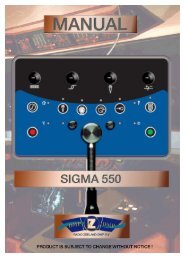
����� ����������<br />
������� ����������������������<br />
A radar map is a combination of map lines<br />
and symbols whereby the user can define<br />
and input the navigation, route planning and<br />
monitoring data on the radar equipment. Map<br />
lines are a navigational facility whereby the<br />
observer can define lines to indicate channels<br />
or traffic separation schemes.<br />
In this radar a radar map may contain 1500<br />
points of mark and line data on map.<br />
270<br />
300<br />
240<br />
���� �<br />
�<br />
330<br />
210<br />
X<br />
000<br />
180<br />
The user can create a radar map on real-time<br />
base while using the radar for navigation or at<br />
leisure time at anchor. The map data is stored<br />
on the EEROM memory which is mounted on<br />
the main processor board.<br />
������Radar map function requires an input<br />
from heading device and positioning<br />
equipment.<br />
030<br />
150<br />
060<br />
120<br />
Navline (by NAV LINE keys)<br />
090<br />
Heading line<br />
Planned route<br />
Approximate coastline
1.34.2 Turning the radar map on/off<br />
1. Use the trackball to select MARK at the<br />
bottom left of the display.<br />
2. Press the [ENTER] key to turn the map on<br />
or off as appropriate.<br />
1.34.3 Entering marks, lines<br />
1. Use the trackball to place the arrow inside<br />
the square with symbol at the upper<br />
left-hand corner of the screen.<br />
2. Use the [LEVEL] control to select mark to<br />
enter. Rotating the control clockwise<br />
selects marks in the following order.<br />
�����<br />
������<br />
�����<br />
X<br />
--<br />
����������� �������� ������ ����<br />
����� ���� ���� ����<br />
Note: The triangle mark appears with the<br />
[LEVEL] control in the fully CCW<br />
position.<br />
3. Use the trackball to select the location for<br />
the mark with the cursor.<br />
4. Press the [MARK] key to inscribe the mark.<br />
To erase a mark, use the trackball to place the<br />
cursor on it and press the [ERASE] key.<br />
Example: How to draw a coastline<br />
1. Select the mark “Coast Line” following<br />
steps 1 and 2 above.<br />
2. Place the cursor on a required position and<br />
press the [MARK] key.<br />
3. Place the cursor at a next position and<br />
press the [MARK] key. One line appears<br />
connecting designated two points.<br />
4. Repeat step 3 to establish the coastline.<br />
The map is stored on the main processor<br />
board.<br />
To enter more than one line, after entering<br />
one line, select LINE CHANGE and press the<br />
[MARK] key. Then, repeat the procedure for<br />
entering marks and lines above.<br />
--<br />
To erase a line segment entered, place the<br />
cursor to a point and then press the [ERASE]<br />
key. For example, if point 4 is to be erased in<br />
the illustration below, line segment 3-4 is<br />
erased. If point 3 is erased, line segments 2-3<br />
and 3-4 are erased and new line segment 2-4<br />
is generated.<br />
1<br />
2<br />
1.34.4 Aligning the radar map<br />
There may be some instances where the map<br />
is not overlaid on the radar picture correctly.<br />
You can align the map as follows:<br />
1. Press the [MENU] key to open the menu.<br />
������ ��<br />
�<br />
DATA ><br />
GRAPH><br />
INITIALIZE<br />
3<br />
MARK<br />
MAP<br />
2. Use the trackball to select OTHERS and<br />
press the [ENTER] key to open the<br />
OTHERS menu.<br />
3. Use the trackball to select MAP.<br />
�������<br />
�<br />
DATA ><br />
GRAPH><br />
INITIALIZE<br />
MAP ALIGN<br />
OFF/SET/ON<br />
MARK<br />
���<br />
4. Use the trackball to select MAP ALIGN.<br />
5. Press the [ENTER] key to select SET.<br />
6. Use the trackball to correct the position.<br />
7. Press the [ENTER] key to select MAP<br />
ALIGN ON.<br />
4<br />
1-23
����� �����������������������<br />
The table below summarizes the various audio and visual alarms and error messages which may<br />
appear on the display.<br />
�������� �������������� ������������� �������<br />
Compass failure* Two beeps COMPASS label reads “*.*”<br />
COMPASS in red.<br />
Check compass.<br />
Own ship lat/lon*<br />
Cursor lat/lon*<br />
Two beeps “*°**.**” in own ship position<br />
and cursor latitude and<br />
longitude position.<br />
EPSF appears in red.<br />
Log failure* Two beeps **.* and SPD appear in red if<br />
speed log is connected. If no<br />
log signal is input for 30 sec.<br />
ROT signal Continuous beeps ROT ALARM appears at the<br />
top of the screen when the<br />
ROT error signal is received.<br />
Trigger signal Two beeps TRIG appears in red at the<br />
screen top when the trigger<br />
signal is lost.<br />
Heading signal Two beeps HL appears in red at the<br />
screen top when the<br />
heading line signal is lost.<br />
Azimuth (bearing)<br />
signal<br />
Two beeps AZI appears in red at the<br />
screen top when the azimuth<br />
signal is lost.<br />
Video signal Two beeps VIDEO appears in red at the<br />
screen top when the video<br />
signal is lost.<br />
���� �<br />
�<br />
Make sure that own ship<br />
position data is fed from<br />
external EPFS.<br />
Check log connection.<br />
Acknowledge the ROT alarm<br />
as follows:<br />
1. Use the trackball to select<br />
the indication ROT<br />
ALARM. The indication<br />
ROT ALARM ACK<br />
replaces ROT ALARM.<br />
2. Press the [ENTER] key to<br />
silence the alarm.<br />
Check SPU Board.<br />
Check the cable connector<br />
between the display unit and<br />
the antenna unit.<br />
Check the cable connector<br />
between the display unit and<br />
the antenna unit.<br />
Check the cable connector<br />
between the display unit and<br />
the antenna unit.<br />
Incorrect keystroke Two beeps None Correct keystroke is<br />
responded by a single beep<br />
provided that KEY BEEP ON<br />
is selected during<br />
installation.<br />
*: Error message appears in red when the NAV ON is selected on the HEADING, SPEED menu.
��� ������������������<br />
���� ��������<br />
������ ��������������<br />
The minimum range is defined by the shortest<br />
distance at which, using a scale of 1.2 km, a<br />
target having an echoing area of 10 m2 is still<br />
shown separate from the point representing<br />
the antenna position.<br />
It is mainly dependent on the pulselength,<br />
antenna height, and signal processing such<br />
as main bang suppression and digital<br />
quantization. It is a good practice to use a<br />
shorter range scale as far as it gives<br />
favorable definition or clarity of picture.<br />
������ ��������������<br />
The maximum detecting range of the radar,<br />
Rmax, varies considerably depending on<br />
several factors such as the height of the<br />
antenna above the waterline, the height of the<br />
target above the water, the size, shape and<br />
material of the target, and the atmospheric<br />
conditions.<br />
Under normal atmospheric conditions, the<br />
maximum range is equal to the radar horizon<br />
or a little shorter. The radar horizon is longer<br />
than the optical one by about 6% because of<br />
the diffraction property of the radar signal.<br />
The Rmax is given in the following equation.<br />
R max = 2.2 x (√h 1) + (√h 2)<br />
Where Rmax: radar horizon (nautical miles)<br />
h1: antenna height (m)<br />
h2 : target height (m)<br />
Optical horizon<br />
Radar horizon<br />
It should be noted that the detection range is<br />
reduced by precipitation (which absorbs the<br />
radar signal).<br />
������ �����������������<br />
There are two important factors in radar<br />
resolution (discrimination): bearing resolution<br />
and range resolution.<br />
������ �������������������<br />
Bearing resolution is the ability of the radar to<br />
display as separate pips the echoes received<br />
from two targets which are at the same range<br />
and close together. It is proportional to the<br />
antenna length and reciprocally proportional<br />
to the wavelength.<br />
������ �����������������<br />
Range resolution is the ability to display as<br />
separate pips the echoes received from two<br />
targets which are on the same bearing and<br />
close to each other. Major contributor to<br />
determine this is a pulselength. Test targets<br />
for determining the range and bearing<br />
resolution are radar reflectors having an<br />
echoing area of 10 m2 .<br />
������ ������������������<br />
Measurement of the range to a target is a very<br />
important function of the radar. Generally, there<br />
are two means of measuring range: the fixed<br />
range rings and the variable range marker<br />
(VRM). The fixed range rings appear on the<br />
screen with a predetermined interval and<br />
provide a rough estimate of the range to a<br />
target. The variable range marker’s diameter is<br />
increased or decreased so that the marker<br />
touches the inner edge of the target, allowing<br />
the operator to obtain more accurate range<br />
measurements.<br />
� ��� �
������ �����������������<br />
One of the most important features of the<br />
radar is how accurately the bearing of a<br />
target can be measured. The accuracy of<br />
bearing measurement basically depends on<br />
the narrowness of the radar beam. However,<br />
the bearing is usually taken relative to the<br />
ship’s heading, and thus, proper adjustment<br />
of the heading line at installation is an<br />
important factor in ensuring bearing accuracy.<br />
To minimize error when measuring the<br />
bearing of a target, put the target echo at the<br />
extreme position on the screen by selecting a<br />
suitable range.<br />
���� �������������<br />
Occasionally echoes appear on the screen at<br />
positions where there is no target or<br />
disappear even if there are targets. They are,<br />
however, recognized if you understand the<br />
reason why they are displayed. Typical false<br />
echoes are shown below.<br />
������ ����������������<br />
Multiple echoes occur when a transmitted<br />
pulse returns from a solid object like a large<br />
ship, bridge, or breakwater. A second, a third<br />
or more echoes may be observed on the<br />
display at double, triple or other multiples of<br />
the actual range of the target as shown below.<br />
Multiple reflection echoes can be reduced<br />
and often removed by decreasing the gain<br />
(sensitivity) or properly adjusting the A/C SEA<br />
control.<br />
Own ship<br />
Target<br />
True<br />
echo<br />
.<br />
Multiple<br />
echoes<br />
��� �<br />
�<br />
������ ����������������<br />
Every time the radar pulse is transmitted,<br />
some radiation escapes on each side of the<br />
major axis. This is called "sidelobe." If a<br />
target exists where it can be detected by the<br />
sidelobes as well as the main lobe, the<br />
sidelobe echoes may be represented on both<br />
sides of the true echo at the same range.<br />
Sidelobes show usually only on short ranges<br />
and from strong targets. They can be reduced<br />
through careful reduction of the gain or<br />
proper adjustment of the A/C SEA control.<br />
Target A<br />
Target B<br />
(Spurious) Target B<br />
(True)<br />
������ �������������<br />
A relatively large target close to your ship<br />
may be represented at two positions on the<br />
screen. One of them is the true echo directly<br />
reflected by the target and the other is a false<br />
echo which is caused by the mirror effect of a<br />
large object on or close to your ship as shown<br />
in the figure below. If your ship comes close<br />
to a large metal bridge, for example, such a<br />
false echo may temporarily be seen on the<br />
screen.<br />
Target ship<br />
Own<br />
ship<br />
Mirror image<br />
of target ship<br />
True<br />
echo<br />
False<br />
echo
������ ���������������<br />
Funnels, stacks, masts, or derricks in the<br />
path of the antenna block the radar beam. If<br />
the angle subtended at the scanner is more<br />
than a few degrees, a non-detecting sector<br />
may be produced. Within this sector targets<br />
cannot be detected.<br />
Blind zone<br />
Radar<br />
mast<br />
Radar<br />
antenna<br />
� ��� �
This page is intentionally left blank.<br />
��� �<br />
�
3. MAINTENANCE<br />
WARNING<br />
Do not open the equipment.<br />
Hazardous voltage which can<br />
cause electrical shock exists<br />
inside the equipment. Only<br />
qualified personnel should<br />
work inside the equipment.<br />
Turn off the radar power<br />
switch before servicing the<br />
antenna unit. Post a warning<br />
sign near the switch<br />
indicating it should not be<br />
turned on while the antenna<br />
unit is being serviced.<br />
Prevent the potential risk of<br />
being struck by the rotating<br />
antenna and exposure to<br />
RF radiation hazard.<br />
Wear a safety belt and hard<br />
hat when working on the<br />
antenna unit.<br />
Serious injury or death can<br />
result if someone falls from<br />
the radar antenna mast.<br />
3.1 Replacement of Fuse<br />
The TX fuse on the rear panel of the display<br />
unit protects the equipment from overcurrent.<br />
If the fuse blows find the cause before<br />
replacing it. Use only a specified fuse; use of<br />
a wrong fuse may not protected the<br />
equipment and void the warranty.<br />
Use the proper fuse.<br />
CAUTION<br />
Use of a wrong fuse can cause fire or<br />
equipment damage.<br />
3-1
���� ������������������������������<br />
Periodic checks and maintenance are important for proper operation of any electronic systems. This<br />
chapter contains maintenance instructions to be followed by the technician to obtain optimum<br />
performance and the longest possible life of the equipment.<br />
��������� ������������ ������������������� ��������<br />
Daily LCD screen The LCD screen will, in time,<br />
accumulate a coating of dust<br />
which tends to dim the picture.<br />
Wipe LCD lightly with soft cloth<br />
to remove dust.<br />
3 to 6<br />
months<br />
6 months to<br />
one year<br />
Exposed nuts and<br />
bolts on antenna<br />
unit<br />
Check for corroded or loosened<br />
nuts and bolts. If necessary,<br />
clean and repaint them thickly.<br />
Replace them if heavily<br />
corroded.<br />
Antenna radiator Check for dirt and cracks on<br />
radiator surface. Thick dirt<br />
should be wiped off with soft<br />
cloth dampened with fresh<br />
water. if a crack is found, apply<br />
a slight amount of sealing<br />
compound or adhesive as a<br />
temporary remedy, then call for<br />
repair.<br />
Terminal strips and<br />
plugs in antenna<br />
unit<br />
Terminal strips,<br />
sockets, earth<br />
terminal<br />
Open antenna cover to check<br />
terminal strip and plug<br />
connections inside. Also check<br />
the rubber gasket of antenna<br />
covers for deterioration.<br />
Check for loose connections.<br />
Check contacts and plugs for<br />
proper seating, etc.<br />
���� �������������������������������<br />
��� �<br />
�<br />
Do not use chemical cleaners to<br />
clean any part of the display unit;<br />
they can remove paint and<br />
markings.<br />
Sealing compound may be used<br />
instead of paint. Apply a small<br />
amount of grease between nuts<br />
and bolts for easy removal in<br />
future.<br />
Do not use plastic solvent<br />
(acetone) for cleaning. If you need<br />
to remove ice from antenna unit,<br />
use a wooden hammer or plastic<br />
head hammer. Crack on the unit<br />
may cause water ingress, causing<br />
serious damages to internal<br />
circuits.<br />
When closing antenna covers in<br />
position, be careful not to catch<br />
loose wires between covers and<br />
unit.<br />
������ ����� ���������������� ��������<br />
Carbon Brush MG120-5X6X11 D8G 10,000 hours<br />
Magnetron MG-5248, X-band, 4 kW 2,000 - 3,000 hours
��� ����������������<br />
���� ���������������������<br />
WARNING<br />
Do not open the equipment.<br />
Hazardous voltage which can<br />
cause electrical shock exists<br />
inside the equipment. Only<br />
qualified personnel should<br />
work inside the equipment.<br />
Turn off the radar power<br />
switch before servicing the<br />
antenna unit. Post a warning<br />
sign near the switch<br />
indicating it should not be<br />
turned on while the antenna<br />
unit is being serviced.<br />
Prevent the potential risk of<br />
being struck by the rotating<br />
antenna and exposure to<br />
RF radiation hazard.<br />
Wear a safety belt and hard<br />
hat when working on the<br />
antenna unit.<br />
Serious injury or death can<br />
result if someone falls from<br />
the radar antenna mast.<br />
This paragraph describes how to cure operational problems, which can be made by observing the<br />
radar picture and using operator controls and keys without opening the display unit or antenna unit.<br />
�������� �������<br />
Cannot turn on the power. Check fuse.<br />
Power is on but nothing<br />
appears on the screen.<br />
Adjust the BRILL control.<br />
Key beep inaudible. Key beep (on or off) is set during installation. (default setting: OFF)<br />
Consult your dealer.<br />
Own ship marker not<br />
shown.<br />
OFF is selected on OWN SHIP POSN DATA menu.<br />
� ��� �
���� ��������������� �<br />
��� � � � ����������������<br />
This paragraph describes how to cure hardware<br />
and software troubles which should be carried<br />
out by qualified service personnel.<br />
������This radar equipment contains complex<br />
modules in which fault diagnosis and repair<br />
down to component level are not practicable by<br />
users. .�<br />
��� �<br />
�<br />
������ �������������������������<br />
All adjustments of radio transmitter during or<br />
coinciding with the installation, servicing, or<br />
maintenance which may affect the proper<br />
operation must be performed by or under the<br />
immediate supervision and responsibility of a<br />
person holding an operator certificate<br />
containing a ship radar endorsement.<br />
As such, every administration sets forth its<br />
own rule; service personnel must be aware of<br />
this kind of competency requirements.<br />
������ �������������<br />
When making a service call to your service<br />
agent, check S/N and symptom beforehand<br />
following the table on the next page.
���� ����������������<br />
A diagnostic test program is provided to<br />
enable testing of major circuit boards in the<br />
radar display unit. Note that the normal radar<br />
picture is lost during this test.<br />
Proceed as follows to execute the diagnostic<br />
test:<br />
1. Press the [MENU] key to open the menu.<br />
The menu appears at the bottom-left corner<br />
of the screen as below.<br />
������ ��<br />
�<br />
DATA ><br />
GRAPH><br />
INITIALIZE<br />
MARK<br />
MAP<br />
2. Use the trackball to select INITIALIZE. The<br />
display now looks as below.<br />
OTHERS ><br />
DATA ><br />
GRAPH> MAP<br />
����������<br />
TUNE<br />
INITIALIZE TEST<br />
MARK<br />
��� �<br />
�<br />
3. Use the trackball to select TEST and press<br />
the [ENTER] key to start the test.<br />
a) Program number appears. The<br />
diagnostic test is executed and the<br />
screen shows test results as shown<br />
below. OKs appear for normal operation.<br />
If NG (No good) appears, consult your<br />
dealer.<br />
b) Small squares and circles displayed at<br />
the bottom of the test result screen are<br />
for testing the keys and controls on the<br />
control head. As you operate these<br />
keys and controls, corresponding<br />
squares are highlighted (key operated)<br />
and digits increment upward or<br />
downward (control operated), indicating<br />
that your key/control operations are<br />
properly recognized.<br />
c) The inputted serial data is read out at the<br />
bottom of the display. Each pressing the<br />
[HL OFF] key changes the sentence. ALL<br />
shows all serial data inputted.<br />
RHRS2005RC TEST<br />
PROGRAM NO ROM RAM EEROM<br />
MAIN 0359163-01.** OK OK OK<br />
ANTENNA SPEED 28 RPM<br />
TRIG FREQ. 1000 Hz<br />
MAG CURRENT 2.5 V<br />
TUNE IND. 1.5 V<br />
000 000 000<br />
�� 000<br />
����� �� � � � 000<br />
To quit press [STBY/XMIT] key twice<br />
ALL CH1..........................<br />
CH2.......................<br />
GA......................<br />
** Program Version No.<br />
4. To show a test pattern press the<br />
[STBY/XMIT] key.<br />
5. To quit the self test, press the [STBY/XMIT]<br />
key again.
��� �����������<br />
This equipment contains one complex module in which fault diagnosis and repair down to<br />
component level is practicable; therefore, parts list is omitted in this manual (IMO A.694(17)/8.3.1).<br />
Only discrete components that may be checked or replaced by the ship personnel are power jack<br />
and a fuse (20 A).<br />
���� �����������������������<br />
������� ����� ��������� ��������<br />
PTU Board 03P9246C 008-493-700<br />
HV Board HV-9017D 008-481-660<br />
SPU Board 03P9277 008-506-040<br />
Fan Motor MMS-06C24-DS-R01 000-128-409<br />
Fuse FGBO 20A AC125V 005-490-015<br />
Fuse Holder F-70 000-123-436<br />
Filter Board 03P9224A 008-492-440<br />
RGB_BUFF Board 03P9229 006-551-050<br />
SPU Board<br />
03P9277<br />
RGB_BUFF Board<br />
03P9229<br />
Filter Board<br />
03P9224A<br />
Fuse Holder<br />
F-70<br />
Fan Motor<br />
MMS-06C24-DS-R01<br />
DC/DC Converter<br />
BTS100-RS6.2A<br />
Processor unit, cover removed<br />
HV Board<br />
HV-9017D<br />
PTU Board<br />
03P9246<br />
� ��� �
���� ���������������������<br />
������� ����� ��������� ��������<br />
TFT Color LCD Module NL128102AC-01F<br />
DIM Board 10P6877<br />
TFT Color LCD Module<br />
NL128102AC28-01F<br />
Display unit, front view<br />
��� �<br />
�
Display unit, rear view<br />
DIM Board<br />
10P6877<br />
� ��� �
���� ���������������������<br />
������� ����� ��������� ��������<br />
Trackball EUA-FTF814B 000-115-533<br />
PANEL Board 03P9278 008-506-060<br />
PANEL Board<br />
03P9278 Trackball<br />
EUA-FTF814B<br />
���� ����������������<br />
Control unit, bottom cover removed<br />
����� ����� ��������� ��������<br />
STC Board 03P9275 008-504-770<br />
MD Board 03P9274 008-504-790<br />
IF Board 03P9276 008-504-750<br />
TB Board 03P9279 008-504-720<br />
MP Board MP-3795 008-312-370<br />
Magnetron MG5248 000-116-121<br />
MIC RU-9360 000-138-979<br />
Motor<br />
D8G-516 30W DC24V 000-631-715 for RSB-0085<br />
D8G-571 000-136-566 for RSB-0086<br />
Reed SW RS-1. NO. 000-478-301<br />
Toggle SW ATK21-W 000-479-243<br />
Circulator RC-3686 000-106-850<br />
��� �<br />
�
STC Board<br />
03P9275<br />
Magnetron<br />
MG5248<br />
RF Unit<br />
MD Board<br />
03P9274<br />
IF Board<br />
03P9276<br />
� ��� �
This page is intentionally left blank.<br />
��� �<br />
�
��� ������������������������������<br />
�<br />
��������������������������������<br />
������<br />
GGA, RMC, RMA, GLL, ZDA, RMC, RMA, VTG<br />
�������<br />
RSD<br />
�������������������������������<br />
������<br />
HDT, HDG, HDM, VHW, RMC, RMA<br />
�������<br />
None<br />
�������������������������������<br />
������<br />
VBW, VTG, VBW, VHW<br />
�������<br />
None<br />
�������������������������������<br />
������<br />
DPT, DBK, DBS, DBT<br />
�������<br />
None<br />
�������������������������<br />
See pages which follow.<br />
� ��� �
������������������������������������������������<br />
CHANNEL 1<br />
OUTPUT<br />
(RSD)<br />
CHANNEL 1<br />
INPUT<br />
CHANNEL 2<br />
INPUT<br />
CHANNEL 3<br />
INPUT<br />
CHANNEL 4<br />
INPUT<br />
TALKER<br />
(60 mA max)<br />
TXD A 4<br />
GND >5<br />
TALKER<br />
(60 mA max)<br />
LISTENER<br />
(2 mA at 2 V)<br />
HDG RXD A >6<br />
HDG RXD B >7<br />
TALKER<br />
(60 mA max)<br />
LISTENER<br />
(2 mA at 2 V)<br />
SPEED RXD A >8<br />
SPEED RXD B >9<br />
TALKER<br />
(60 mA max)<br />
LISTENER<br />
(2 mA at 2 V)<br />
DEPTH RXD A >10<br />
DEPTH RXD B >11<br />
GND >12<br />
03P9227<br />
R136 470<br />
��� �<br />
�<br />
CR25 1SS181<br />
R135 470<br />
CR24<br />
1SS181<br />
U79 SN75ALS1720W<br />
16<br />
17<br />
U66 PC400<br />
1<br />
3<br />
U65 PC400<br />
1<br />
3<br />
18<br />
R31 470<br />
U66 PC400<br />
CR6 1<br />
1SS181 4<br />
R32 470<br />
CR7<br />
1SS181<br />
3<br />
U66 PC400<br />
1<br />
3<br />
Select<br />
4<br />
4<br />
U34<br />
TC74HC04AF<br />
13<br />
8<br />
9<br />
4<br />
5<br />
6<br />
U43<br />
U43<br />
4<br />
3<br />
2<br />
U43<br />
1<br />
10<br />
SPU BOARD<br />
UART
������������������������<br />
����������������<br />
����������������������������������������������<br />
Time, position and fix related data for a GPS receiver.<br />
Differential reference station ID, 0000-1023 *1<br />
Age of differential GPS data *1<br />
Unit of geoid height, m *1<br />
Geoid height (-999 - 0999) *1<br />
Unit of antenna height, m *1<br />
Antenna height (-9999 - 99999) *1 Checksum<br />
Horizontal dilution of precision (00 - 99) *1<br />
$--GGA, hhmmss.ss, 1111.11, a, yyyyy.yy, a, x, xx, x.x, x.x, M, x.x, M, x.x, xxxx*hh<br />
Number of satellite in use, 00-12<br />
GPS quality indicator<br />
Longitude - E/W<br />
0= fix not available or invalid<br />
Latitude - N/S<br />
1= GPS SPS mode, fix valid<br />
UTC of position *1<br />
2= differential GPS, SPS mode, fix valid<br />
*1: Not used<br />
3= GPS PPS mode, fix valid<br />
4= Real Time Kinematic. Satellite system<br />
used in RTK mode with fixed integers<br />
5= Float RTK. Satellite system used in RTK<br />
mode with floating integers<br />
� ��� �
����������������������������������������������<br />
Latitude and longitude of vessel position, time of position fix and status.<br />
$--GLL, 1111.11, a, yyyyy.yy, a, hhmmss.ss, A,a*hh<br />
Latitude, N/S<br />
*1: Eidition 2 only, *2: Not used<br />
�����������������������������������������������<br />
��� �<br />
�<br />
Mode indicator (See note on page 9.3.) *1<br />
Checksum<br />
Status (A = data valid V = data invalid)<br />
UTC of position *2<br />
Longitude, E/W<br />
Position, course and speed data provided by a LORAN-C receiver. Time differences A and B are those<br />
used in computing latitude/longitude. Checksum is mandatory in this sentence. This sentence is<br />
transmitted at intervals not exceeding 2 s and is always accompanied by RMB when a destination<br />
waypoint is active. RMA and RMB are the recommended minimum data to be provided by a LORAN-C<br />
receiver. All data fields must be provided, null fields used only when data is temporarily unavailable.<br />
Checksum, mandatory for RMA<br />
Magnetic variation (000.0 - 179.9°), degrees E/W *2<br />
Bearing, degrees *2<br />
Speed over ground, knots 2*<br />
Time difference B, 2*<br />
(00000.0 - 99999.9 µs)<br />
Time difference A, *2<br />
(00000.0 - 99999.9 µs)<br />
$--RMA, A, 1111.11, a, yyyyy.yy, a, x.x, x.x, x.x, x.x, x.x, a,a*hh<br />
Longitude, degrees, E/W<br />
Latitude, degrees, N/S<br />
Status (A = data valid, V = blink, cycle or SNR warning)<br />
*1: Edition 2 only, *2: Not used<br />
Mode indicator (See note on page 9.3.) *1
�������������������������������������������<br />
Time, date, position, course and speed data provided by a GPS or TRANSIT navigation receiver.<br />
Checksum is mandatory in this sentence. This sentence is transmitted at intervals not exceeding 2 s and<br />
is always accompanied by RMB when a destination waypoint is active. RMC and RMB are the<br />
recommended minimum data to be provided by a GPS or TRANSIT receiver. All data fields must be<br />
provided, null fields used only when data is temporarily unavailable.<br />
Checksum, mandatory for RMC<br />
Magnetic variation (000.0 - 180.0°), degrees E/W *2<br />
Date: dd/mm/yy *2<br />
Course over ground, degrees*2<br />
$--RMC, hhmmss.ss, A, 1111.11, a, yyyyy.yy, a, x.x, x.x, xxxxxx, x.x, a,a*hh<br />
Speed over ground, knots*2<br />
Longitude, E/W<br />
Latitude, N/S<br />
Receive status (V = navigation receiver warning)<br />
UTC of position fix *2<br />
*1: Eidition 2 only, *2: Not used<br />
�����������������������������������������<br />
The actual course and speed relative to the ground.<br />
$--VTG, x.x, T, x.x, M, x.x, N, x.x, K,a *hh<br />
Speed over ground, km/h<br />
Speed over ground, knots<br />
Course over ground, degrees magnetic<br />
Course over ground, degrees true<br />
*1: Eidition 2 only<br />
Mode indicator (See note on page 9.3.) *1<br />
Mode indicator (See note on page<br />
9.3.) *1<br />
� ��� �
���������������<br />
����������������<br />
$HDT,x.x,T*hh<br />
Checksum<br />
Heading, degrees true<br />
������������������������������������<br />
$--HDG,x.x,x.x,a,x.x,a*hh<CR><LF><br />
| | | | |<br />
| | | | | Checksum<br />
| | | +--+----------- Magnetic variation, degrees E/W<br />
| +--+----------------- Magnetic deviation, degrees E/W<br />
+------------------------ Magnetic sensor heading, degrees<br />
�����������������������������<br />
The heading to which the vessel points and the speed of the vessel relative to the water.<br />
$--VHW, x.x, T, x.x, M, x.x, N, x.x, K *hh<br />
�<br />
�<br />
*1: Not used<br />
Checksum<br />
Water speed, K = km/h<br />
Water speed, knots Priority: N>K<br />
Heading (M = magnetic bearing)*1<br />
Heading (T = true bearing)*1<br />
� ��� �
���������������<br />
�����������<br />
Water depth relative to the transducer and offset of the measuring transducer. Positive offset numbers<br />
provide the distance from the transducer to the waterline. Negative offset numbers provide the distance<br />
from the transducer to the part of the keel of interest.<br />
$--DPT, x.x, x.x, x.x*hh<br />
�<br />
Maximum range scale in use *1<br />
Checksum<br />
Offset from transducer, in meters = distance from transducer to water-line<br />
Water depth relative to the transducer, in meters<br />
*1: Edition 2 only, however not used<br />
����������������������������<br />
Water depth referenced to the transducer.<br />
$--DBT, x.x, f, x.x, M, x.x, F*hh<br />
�<br />
Checksum<br />
Water depth, fathoms<br />
Water depth, m<br />
Water depth, feet<br />
� ��� �
����������<br />
[MENU] key<br />
OTHERS MARK<br />
CURSOR & EBL REF MODE (TRUE, REL)<br />
2 EBL·VRM (OFF, ON)<br />
STERN MARK (OFF, ON)<br />
MAP<br />
DATA> HEADING, SPEED HEADING DATA (OFF, ON)<br />
SPEED DATA (OFF, km/h, kt)<br />
SPEED MODE (NAV, LOG)<br />
OS-POSN, DEPTH OWN SHIP POSN DATA (OFF, ON)<br />
DEPTH DATA (OFF, m, ft, FA)<br />
DATE, TIME DATE TIME (OFF, UTC, LOCAL)<br />
LOCAL TIME ADJ (-13:30 - +13:30, 00:00)<br />
GRAPH> ROT ROT GRAPH (OFF, ON)<br />
ROT OFFSET ADJ (Offsets ROT graph.)<br />
ROT GAIN ADJ (Adjusts ROT graph.)<br />
RUDDER RUDDER GRAPH (OFF, ON)<br />
RUDDER OFFSET ADJ (Offsets rudder graph.)<br />
RUDDER GAIN ADJ (Adjusts rudder graph.)<br />
AUTOPILOT AUTOPILOT GRAPH (OFF, ON)<br />
AUTOPILOT OFFSET ADJ (Offsets autopilot graph.)<br />
AUTOPILOT GAIN ADJ (Adjusts autopilot graph.)<br />
INITIALIZE TUNE INITIALIZE (Initializes tuning.)<br />
TEST (Conducts diagnostic test.)<br />
Default settings shown in bold italics.<br />
MAP ALIGN (OFF, SET, ON)<br />
���� �
2.10 Duplexer Ferrite Circulator with diode limiter<br />
2.11 Noise Figure 9 dB nominal<br />
3<br />
3<br />
DISPLAY UNIT<br />
3.1 Display 46 cm (18.1-inch) diagonal display (359 x 287 mm) TFT color<br />
LCD, effective display area: 270 mm<br />
3.2 Presentation Mode Relative motion head-up<br />
3.3 Range, Range Interval, Number of Rings<br />
Range (km) 0.25 0.5 0.8 1.2 1.6 2 4 8 16 32 64<br />
Ring Interval (km) 0.05 0.1 0.2 0.2 0.4 0.4 1 2 4 8 16<br />
Number of Rings 5 5 4 6 4 5 4 4 4 4 4<br />
3.4 Radar Display Area Continuous forward range extension to 150% with<br />
full 100% range aft.<br />
3.5 Off-centering Forward range extension to 183% of range in use<br />
3.6 Minimum Range 15 m (0.25-1.2 km range)<br />
3.7 Range Discrimination 15 m (0.25-1.2 km range)<br />
3.8 Bearing Readout By EBL, 0.1º resolution<br />
3.9 Range Accuracy ±1 % of range or 10 m, whichever is the greater<br />
3.10 Bearing Accuracy ±1º<br />
3.11 Echo Trails 2 scan: 15 sec/ 30 sec/ 1 min/ 3 min (relative trail / true trail*)<br />
3.12 Radar Map** 1500 point<br />
3.13 Echo Average* Scan to scan correlation<br />
3.14 Nav lines Two independently adjustable lines parallel to ship’s heading<br />
3.15 ROT/Autopilot indicator OFF, 30 , 90, 300°/min<br />
3.16 Rudder Angle/Follow-up Indicator<br />
OFF, 30, 90, 120, 180°<br />
*: Heading information and L/L (or speed) data are required.<br />
**: Radar map requires L/L data.<br />
4 INTERFACES<br />
4.1 Inputs L/L, speed, compass and depth (IEC 61162-1),<br />
rate-of -turn, autopilot (ROT/follow-up), rudder angle,<br />
4.2 Outputs Repeater display outputs (2 ports: radar video, trigger, heading,<br />
bearing pulses)<br />
4.3 Repeater radar inputs Radar video, trigger, heading, bearing pulses<br />
SP - 2 E3488S02A
5 POWER SUPPLY<br />
5.1 Input Voltage 24-32 VDC: 7.5-5.6 A (28 rpm)<br />
24-32 VDC: 8.1-6.1 A (42 rpm)<br />
5.2 Power Consumption 180 W (28 rpm), 200 W (42 rpm)<br />
5.3 For AC supply (optional rectifier/transformer required)<br />
RU-1746B-2 (rectifier) Input: 115/230 VAC, 50-60 Hz, 1 phase<br />
Output: 24VDC, 13 A max.<br />
RU-1803 (transformer) Input: 440 VAC, 50-60 Hz, 1 phase<br />
Output: 115 VAC, 7 A max.<br />
6 ENVIRONMENTAL CONDITIONS<br />
6.1 Ambient Temperature Antenna Unit: -25°C to +70°C<br />
Display Unit: -15°C to +55°C<br />
6.2 Relative Humidity<br />
6.3 Water Protection<br />
93 % (±3%) at +40°C<br />
Antenna Unit IPX6 (IEC 60529)<br />
Display Unit For use in protected area<br />
Processor Unit For use in protected area<br />
6.4 Vibration IEC 60945<br />
7 COATING COLOR<br />
7.1 Display Unit Dark gray (N3.0)<br />
7.2 Processor Unit Dark gray (N3.0)<br />
7.3 Scanner Unit White (N9.5)<br />
8 X-RADIATION<br />
No components are used executing a dose rate > 5 �J/kgh (0.5 mrem/h) at 50 mm.<br />
SP - 3 E3488S02A
�����<br />
��<br />
A/C RAIN control 1-8<br />
A/C SEA control 1-8<br />
Alarms 1-24<br />
Autopilot graph 1-18<br />
adjusting ................................................... 1-20<br />
description ................................................ 1-18<br />
on/off......................................................... 1-19<br />
AUTOPILOT menu 1-19<br />
��<br />
Background color 1-15<br />
Barge 1-14<br />
Bearing measurement 1-11<br />
BRILL control 1-4<br />
Brilliance<br />
CRT............................................................. 1-4<br />
data........................................................... 1-15<br />
markers..................................................... 1-15<br />
panel ......................................................... 1-15<br />
programming sets ..................................... 1-16<br />
��<br />
Contrast 1-10<br />
Control description 1-3<br />
Cursor data 1-13<br />
Cursor data format 1-13<br />
��<br />
Data<br />
brilliance.................................................... 1-15<br />
DATE, TIME menu 1-17<br />
Diagnostic test 4-4<br />
��<br />
EBL control 1-11<br />
Echo averaging 1-10<br />
Echo color 1-15<br />
Echo programming 1-16<br />
Echo stretch 1-9<br />
Error messages 1-24<br />
��<br />
�������<br />
False echoes<br />
multiple echoes........................................... 2-2<br />
shadow sectors........................................... 2-3<br />
sidelobe echoes.......................................... 2-3<br />
virtual image ............................................... 2-2<br />
FTC (Fast Time Constant) 1-8<br />
Fuse replacement 3-1<br />
��<br />
GAIN control 1-7<br />
Graphs<br />
adjusting ................................................... 1-19<br />
description ................................................ 1-18<br />
on/off......................................................... 1-18<br />
scale ......................................................... 1-19<br />
��<br />
Heading input 1-17<br />
Heading line 1-14<br />
HEADING, SPEED menu 1-17<br />
HL OFF key 1-14<br />
��<br />
Interference rejector 1-9<br />
��<br />
Legends 1-6<br />
��<br />
Maintenance 3-2<br />
Mark entry 1-23<br />
MARK key 1-23<br />
Markers 1-6<br />
MENU key 1-12<br />
MENU operation 1-12<br />
Menu tree 1<br />
Multiple echoes 2-2
��<br />
Nav lines 1-21<br />
Noise rejector 1-9<br />
��<br />
OFF CENTER key 1-12<br />
Offset EBL 1-12<br />
OS POSN menu 1-17<br />
Own ship marker 1-14<br />
��<br />
Parts list 5-1<br />
POWER switch 1-1<br />
Programming brilliance, echo 1-16<br />
PULSE key 1-7<br />
��<br />
Quick start 1-2<br />
��<br />
Radar map 1-22<br />
RANGE control 1-7<br />
Range measurement<br />
range rings................................................ 1-10<br />
VRM.......................................................... 1-11<br />
ROT graph<br />
adjusting ................................................... 1-19<br />
description ................................................ 1-18<br />
on/off......................................................... 1-19<br />
ROT menu 1-19<br />
Rudder graph 1-18<br />
�������<br />
adjusting ................................................... 1-19<br />
description ................................................ 1-18<br />
on/off......................................................... 1-19<br />
RUDDER menu 1-19<br />
��<br />
Shadow sectors 2-3<br />
Sidelobe echoes 2-2<br />
Speed input 1-17<br />
STBY/XMIT switch 1-2<br />
Stern mark 1-14<br />
System configuration v<br />
��<br />
Target trails<br />
color.......................................................... 1-14<br />
erasing...................................................... 1-13<br />
reference (true or relative)........................ 1-13<br />
starting...................................................... 1-13<br />
Time input 1-17<br />
Troubleshooting<br />
technician ................................................... 4-2<br />
user............................................................. 4-1<br />
Tuning<br />
automatic .................................................... 1-5<br />
initialization ................................................. 1-4<br />
manual........................................................ 1-5<br />
��<br />
Virtual image 2-2<br />
VRM control 1-11