Create successful ePaper yourself
Turn your PDF publications into a flip-book with our unique Google optimized e-Paper software.
2 INSTALLATION<br />
2-8<br />
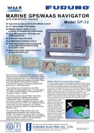
1. Making sure each antenna element is correctly oriented, fix each with its nut.<br />
Write the corresponding arm number on each coaxial cable, using a magic<br />
marker. (When connecting with the coaxial cables from the processor unit it<br />
is necessary to match correct antenna element number with coaxial cable<br />
color.)<br />
Arm [1] 1<br />
Arm [2] 2<br />
Arm [3] 3<br />
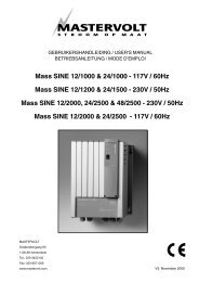
2. Temporarily fix the pedestal and support plate to the antenna mast as shown<br />
in the illustration below. (The pedestal and support plate will be welded to the<br />
antenna mast after confirming that the installation site is suitable, following<br />
paragraph 2.6.)<br />
Note: If U-bolts are used to temporarily fix the pedestal and support plate,<br />
DO NOT overtighten them – overtightening may deform the pedestal.<br />
Antenna Mast<br />
(Local supply<br />
(�50 mm or more)<br />
PEDESTAL<br />
Clamp<br />
BOW<br />
Support Plate<br />
How to temporarily fix the support plate and pedestal to the antenna mast<br />
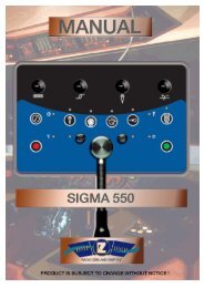
3. Set the antenna unit to the pedestal.<br />
3<br />
Flat Washer<br />
Spring Washer<br />
Nut<br />
1<br />
2<br />
Coaxial Cable Identification<br />
Arm [1]: 1<br />
Arm [2]: 2<br />
Arm [3]: 3<br />
Fixing antenna unit to pedestal