You also want an ePaper? Increase the reach of your titles
YUMPU automatically turns print PDFs into web optimized ePapers that Google loves.
<strong>SATELLITE</strong> <strong>COMPASS</strong><br />
SC-50
SAFETY INSTRUCTIONS<br />
Safety Instructions for the Operator Safety Instructions for the Installer<br />
WARNING<br />
Do not disassemble or modify the<br />
equipment.<br />
Fire, electrical shock or serious injury can<br />
result.<br />
Immediately turn off the power at the<br />
switchboard if the equipment is emitting<br />
smoke or fire.<br />
Continued use can cause fatal damage to<br />
the equipment. Contact a FURUNO agent<br />
for service.<br />
Do not place liquid-filled containers on<br />
the top of the processor unit.<br />
Fire or electrical shock may result if the<br />
liquid enters the equipment.<br />
Use the proper fuse.<br />
ELECTRICAL SHOCK HAZARD<br />
Do not open the equipment.<br />
Only qualified personnel<br />
should work inside the<br />
equipment.<br />
Use of a wrong fuse can damage the<br />
equipment and cause fire.<br />
CAUTION<br />
No one navigation device should ever<br />
be solely replied upon for the navigation<br />
of a vessel.<br />
Always confirm position against all available<br />
aids to navigation (incl. nautical charts),<br />
for safety of vessel and crew.<br />
WARNING<br />
Turn off the power at the switchboard<br />
before beginning the installation.<br />
Fire or electrical shock can result if the<br />
power is left on.<br />
Do not install the equipment where it<br />
may get wet from rain or water splash.<br />
Water in the equipment can cause fire,<br />
electrical shock or damage to the equipment.<br />
NOTICE<br />
Observe the following compass safe<br />
distances to prevent interference to a<br />
magnetic compass:<br />
Display unit<br />
SC-502<br />
Processor unit<br />
SC-501<br />
Antenna unit<br />
SC-303<br />
Antenna unit<br />
SC-603<br />
WARNING<br />
To avoid electrical shock, do not<br />
remove cover. No user-serviceable<br />
parts inside.<br />
Standard<br />
Compass<br />
Steering<br />
Compass<br />
0.5 m 0.3 m<br />
1.3 m 0.8 m<br />
0.3 m 0.3 m<br />
0.3 m 0.3 m<br />
WARNING LABEL<br />
A warning label is attached to the<br />
processor unit. Do not remove the label.<br />
If the label is missing or damaged,<br />
contact a FURUNO agent or dealer<br />
about replacement.<br />
WARNING LABEL<br />
Name: Warning Label (1)<br />
Type: 86-003-1011-0<br />
Code No.: 100-236-230<br />
i
TABLE OF CONTENTS<br />
FOREWORD ..................................................................................................................iv<br />
SYSTEM CONFIGURATION ...........................................................................................v<br />
EQUIPMENT LIST..........................................................................................................vi<br />
1 PRINCIPLE OF OPERATION................................................................................. 1-1<br />
2 INSTALLATION...................................................................................................... 2-1<br />
2.1 Mounting Considerations..................................................................................................... 2-1<br />
2.1.1 Antenna unit............................................................................................................. 2-1<br />
2.1.2 Display unit, processor unit...................................................................................... 2-3<br />
2.2 Installing the Antenna Units ................................................................................................. 2-4<br />
2.2.1 Antenna unit SC-303 ............................................................................................... 2-4<br />
2.2.2 Antenna unit SC-603 ............................................................................................... 2-7<br />
2.3 Installing the Processor Unit.............................................................................................. 2-12<br />
2.3.1 Deck, bulkhead mount ........................................................................................... 2-12<br />
2.3.2 Installation on the underside of a desk .................................................................. 2-13<br />
2.4 Installing the Display Unit .................................................................................................. 2-14<br />
2.4.1 Desktop, overhead mounting................................................................................. 2-14<br />
2.4.2 Flush mount ........................................................................................................... 2-14<br />
2.5 Wiring................................................................................................................................. 2-16<br />
2.6 Initial Settings .................................................................................................................... 2-19<br />
2.6.1 Confirming satellite status; choosing mounting method........................................ 2-19<br />
2.6.2 Choosing heading source ...................................................................................... 2-20<br />
2.7 Connection of External Equipment.................................................................................... 2-21<br />
2.7.1 General wiring........................................................................................................ 2-21<br />
2.7.2 Fabrication of cables.............................................................................................. 2-22<br />
3 OPERATION........................................................................................................... 3-1<br />
3.1 Controls................................................................................................................................ 3-1<br />
3.2 Turning the Power On/Off.................................................................................................... 3-2<br />
3.3 Panel Illumination, Display Contrast.................................................................................... 3-2<br />
3.4 Choosing a Display..............................................................................................................3-3<br />
3.4.1 Description of displays............................................................................................. 3-3<br />
3.5 DGPS Alarm Setup.............................................................................................................. 3-6<br />
3.6 Confirming Satellite Status .................................................................................................. 3-7<br />
3.7 GPS Setup........................................................................................................................... 3-8<br />
3.7.1 Displaying the GPS setup menu.............................................................................. 3-8<br />
3.7.2 GPS SETUP menu description................................................................................ 3-8<br />
3.8 Output Data.......................................................................................................................... 3-9<br />
3.8.1 Heading.................................................................................................................... 3-9<br />
3.8.2 Log pulse ............................................................................................................... 3-12<br />
3.9 System Setup ....................................................................................................................3-13<br />
3.9.1 Geodetic data......................................................................................................... 3-13<br />
3.9.2 Units of measurement............................................................................................ 3-14<br />
3.9.3 Using local time...................................................................................................... 3-14<br />
3.9.4 Time format............................................................................................................ 3-14<br />
3.9.5 Demonstration mode ............................................................................................. 3-15<br />
ii
3.10 WAAS/DGPS Setup........................................................................................................... 3-16<br />
3.11 OTHERS Menu.................................................................................................................. 3-19<br />
3.12 TRIP Menu......................................................................................................................... 3-20<br />
3.13 Resetting Distance Run ..................................................................................................... 3-21<br />
4 MAINTENANCE, TROUBLESHOOTING................................................................4-1<br />
4.1 Preventive Maintenance ...................................................................................................... 4-1<br />
4.2 Troubleshooting ................................................................................................................... 4-2<br />
4.3 Diagnostics .......................................................................................................................... 4-3<br />
4.4 Program Number ................................................................................................................. 4-7<br />
4.5 Clearing Data....................................................................................................................... 4-7<br />
4.6 Replacement of Battery ....................................................................................................... 4-8<br />
4.7 Replacement of Fuse........................................................................................................... 4-9<br />
4.8 Error Messages ................................................................................................................... 4-9<br />
APPENDIX ................................................................................................................AP-1<br />
SPECIFICATIONS.....................................................................................................SP-1<br />
INDEX...........................................................................................................................4-1<br />
iii
FOREWORD<br />
A Word to the Owner of the SC-50<br />
Features<br />
iv<br />
FURUNO Electric Company thanks you for purchasing the FURUNO SC-50<br />
Satellite Compass. We are confident you will discover why the FURUNO name<br />
has become synonymous with quality and reliability.<br />
For over 50 years FURUNO Electric Company has enjoyed an enviable<br />
reputation for quality and reliability throughout the world. This dedication to<br />
excellence is furthered by our extensive global network of agents and dealers.<br />
Your satellite compass is designed and constructed to meet the rigorous<br />
demands of the marine environment. However, no machine can perform its<br />
intended function unless properly installed and maintained. Please carefully read<br />
and follow the operation, installation and maintenance procedures set forth in<br />
this manual.<br />
We would appreciate feedback from you, the end-user, about whether we are<br />
achieving our purposes.<br />
Thank you for considering and purchasing FURUNO.<br />
The SC-50 is a new satellite compass designed with FURUNO’s advanced GPS<br />
kinematic technology. This compass finds a wide range of applications for any<br />
type of ships and mobile units at sea or on land.<br />
The main features are<br />
• Perfect for use as heading sensor for Radar/ARPA, AIS, ECDIS, scanning<br />
sonar, and video plotter<br />
• There are no mechanical parts such as gimbals or rotating motor, thus the<br />
compass is free from routine maintenance<br />
• The performance is not affected by geomagnetism thus it is suitable for use on<br />
any vessel<br />
• No need for speed correction like a gyrocompass<br />
• Short settling time - three minutes<br />
• Meets the following requirements: IMO MSC. 116(73), ISO/FDIS 22090-3,<br />
IMO A. 694(17), IEC 60945 (2002-08), IEC 61162 (2000).
SYSTEM CONFIGURATION<br />
The SC-50 consists of an antenna, a display unit and a processor unit. The<br />
tri-antenna system accommodates three antennas/receiver units and is available<br />
in a low-profile radome type or open type. The tri-antenna system helps reduce<br />
the influence of ship's motion (rolling).<br />
Analog pitch<br />
Analog roll<br />
Log/Heading alarm<br />
(Contact)<br />
External heading data<br />
Antenna Unit<br />
SC-303<br />
Processor Unit<br />
SC-501<br />
12-24 VDC<br />
Category of Units<br />
Processor Unit: Protected from weather<br />
Display Unit: Protected from weather<br />
Antenna Unit: Exposed to weather<br />
OR<br />
Antenna Unit<br />
SC-603<br />
3<br />
2<br />
Display Unit<br />
SC-502<br />
6 ports for Heading or Navigation Data<br />
(5 AD-10/IEC 61162 ports, 1 AD-10 port)<br />
External DPGS<br />
Beacon Receiver<br />
System configuration<br />
: Option<br />
v
EQUIPMENT LIST<br />
Standard supply<br />
vi<br />
Name Type Code No. Qty Remarks<br />
Antenna Unit<br />
SC-303 ─ Choose Radome type<br />
SC-603 ─<br />
one Open type<br />
Display Unit SC-502 ─ 1<br />
Processor Unit SC-501 ─ 1<br />
Installation<br />
Materials<br />
CP20-02600 000-041-905 1<br />
CP20-02203 004-380-660 1<br />
For antenna unit<br />
CP20-02601,<br />
MJ-A7SPF0006-100<br />
For display unit<br />
Tapping screw<br />
(5X20, 4 pcs.)<br />
Spare Parts SP20-00901 004-377-600 1 For processor unit<br />
Optional equipment<br />
Name Type Code No. Qty Remarks<br />
Antenna CP20-01700 004-372-110 30 m<br />
1<br />
Cable Set CP20-01710 004-372-120<br />
50 m<br />
Antenna<br />
Cable<br />
TPPX6-3D2V-15M 000-143-559 1<br />
Flush Mount F OP20-29 000-041-405 1 For display unit<br />
Flush Mount S OP20-17 000-040-720 1 For display unit<br />
3 pcs., for<br />
antenna unit<br />
Extension OP08-15-30 004-396-440 For DGPS, 30 m<br />
1<br />
Cable OP08-15-60 004-396-450<br />
For DGPS, 60 m<br />
Antenna<br />
Cable Set<br />
OP08-17 004-392-510 1 For DGPS
1 PRINCIPLE OF OPERATION<br />
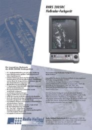
Own ship's heading can be determined by decoding the data in the carrier<br />
frequency in addition to ordinary GPS parameters. In principle, a pair of two<br />
antennas A1(ref) and A2(fore), each connected with an associated GPS engine<br />
and processor, are installed along the ship's fore-and-aft line. GPS systems at<br />
A1 and A2 calculate the range and azimuth to the satellite. Difference in range<br />
between A1 and A2 is ∆λ + nλ where λ is 19 cm. “n” is automatically found<br />
during the initialization stage by receiving three satellites. A fraction of a carrier<br />
wavelength, ∆λ, is processed by FURUNO’s advanced kinematic technology in<br />
geographical survey, thus determining a vector (range and orientation) A1 to A2.<br />
In reality, a third antenna is used to reduce the influence of pitch, roll and yaw,<br />
and five satellites are processed to process 3D data. If the GPS signal is blocked<br />
by a tall building or the vessel is under a bridge, the 3-axis solid-state angular<br />
rate gyros in the processor unit take place of the satellite compass, maintaining<br />
the current heading continuously.<br />
Antenna A3<br />
∆λ<br />
Antenna A1<br />
Heading<br />
θ<br />
nλ<br />
λ<br />
Vector to decide heading<br />
Principle of satellite compass operation<br />
Antenna A2<br />
Fore-and-aft line<br />
Difference between the<br />
range from satellite to<br />
antenna 1 and the range<br />
to antenna 2.<br />
1-1
1 PRINCIPLE OF OPERATION<br />
1-2<br />
(This page intentionally left blank.)
2 INSTALLATION<br />
2.1 Mounting Considerations<br />
2.1.1 Antenna unit<br />
General<br />
• Keep the length of the antenna cable in mind when selecting a mounting<br />
location.<br />
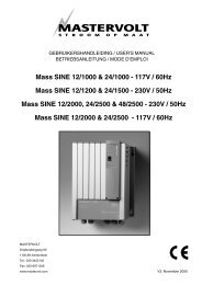
Installing the antenna above superstructures<br />
• The antenna must be mounted above all other structures on the vessel to<br />
obtain an unobstructed view of the satellites regardless of vessel heading.<br />
Failure to do so will cause shadows and multipath reflection problems.<br />
Mast<br />
SC-series Antenna<br />
Radar Antenna<br />
Bridge<br />
Example of antenna installed above all superstructures<br />
Installing the antenna below superstructures<br />
If it is not possible to mount the<br />
antenna above all superstructures on<br />
the vessel, as shown in the illustration<br />
above, shading and multipath<br />
problems may occur on at least one<br />
heading, and possibly more. To<br />
possibly avoid those problems,<br />
observe the guidelines in this section.<br />
NOTICE<br />
If the antenna is installed below any<br />
superstructure, the installation must<br />
be done over a two-day period, following<br />
the procedure in the service manual.<br />
At least 12 hours are required to capture<br />
tracking data to measure multipath indexes<br />
and locate areas of shading.<br />
2-1
2. INSTALLATION<br />
2-2<br />
• The horizontal separation between the antenna and masts must be as follows:<br />
Mast diameter Separation distance (minimum)<br />
10 cm 1.5 m<br />
30 cm 3 m<br />
SC-50’s<br />
antenna<br />
Horizontal<br />
separation<br />
distance<br />
Mast, etc.<br />
Horizontal separation between antenna and masts<br />
• The field of view above the antenna should be as shown below, ±80° against<br />
zenith. To avoid reflections from masts and the like, locate the antenna well<br />
away from the shadows of the radar mast, etc.<br />
Zenith<br />
-80� +80�<br />
SIDE VIEW<br />
Antenna and field of view<br />
SC-series antenna<br />
• Referring to the illustration below, locate the antenna away from objects which<br />
might block reception, such as a mast.<br />
TOP VIEW<br />
Less than 10�<br />
Mast, etc.<br />
• Locate the antenna unit above the radar antenna, out of the radar beam.<br />
SC-series Antenna<br />
Radar Antenna
Location influenced<br />
by reflected wave.<br />
SC-series<br />
Antenna<br />
2.1.2 Display unit, processor unit<br />
Radar Antenna<br />
Bridge<br />
2 INSTALLATION<br />
Reception blocked by mast.<br />
Example of antenna installed below superstructures<br />
• Choose a location where vibration and shock are minimal.<br />
• Install the units well away from locations subject to rain and water splash.<br />
• Locate the units away from air conditioner vents.<br />
• Keep the units out of direct sunlight because of heat that can build up inside<br />
their cabinets.<br />
• Choose a well-ventilated location.<br />
• For the display unit, choose a location where it can be easily operated.<br />
• Leave sufficient space around the units to permit access for maintenance. See<br />
the outline drawing for recommended maintenance space.<br />
2-3
2 INSTALLATION<br />
2.2 Installing the Antenna Units<br />
2.2.1 Antenna unit SC-303<br />
2-4<br />
Note: “Bird-repellent fixtures” may be attached to the antenna cover to prevent<br />
birds from alighting on the cover. If it is more convenient to attach them<br />
before fixing the antenna unit to the mounting location, do step 9 before<br />
fixing the antenna unit.<br />
NOTICE<br />
Fasten the antenna to the mounting<br />
location lastly if it is more convenient<br />
to connect the antenna cable before<br />
mounting the antenna unit.<br />
1. Prepare a mounting platform (wood, steel or aluminum) in accordance with<br />
the illustration shown below. If corrosive material is used, take necessary<br />
anti-corrosion measures.<br />
Note: When drilling holes in the platform, be sure they are parallel with the<br />
fore-and-aft line.<br />
2. Fasten the antenna unit to the platform with four sets of M10 hex. bolts,<br />
spring washers and flat washers, orienting it as shown below. (The bow mark<br />
(�) on the antenna should face the bow.) The torque for the hex. bolts<br />
should be between 19.6-24.5 Nm.<br />
NOTICE<br />
Do not open the antenna.<br />
This installation does not require removal<br />
of the antenna cover.<br />
240<br />
160<br />
240<br />
160<br />
F<br />
R<br />
U<br />
U<br />
Mounting dimensions for antenna, orienting the antenna<br />
N<br />
BOW<br />
Fixing Hole<br />
(�11 mm)<br />
Flat Washer<br />
Spring Washer<br />
Hex. Bolt
3. Coat exposed parts of nuts, bolts and washers with silicone sealant.<br />
Radome<br />
base<br />
Platform<br />
Coat with<br />
silicone sealant.<br />
Coating bolt, nut and washers with silicone sealant<br />
2 INSTALLATION<br />
4. Connect the three coaxial cables coming from the antenna unit to the<br />
appropriate coaxial cables on the antenna cable, referring to the table below.<br />
Cable from antenna<br />
(no. marked on cable)<br />
ANT 1 No color<br />
ANT 2 Yellow<br />
ANT 3 Red<br />
Cable<br />
TTPX6-3D2V-15M<br />
5. Cover the antenna connectors with vulcanizing tape and vinyl tape, for<br />
waterproofing. Tie tape ends with a cable tie.<br />
Waterproofing the antenna connector<br />
6. Set the joints of the coaxial cables into the cavity in the antenna base.<br />
7. Pass two cable ties (long life, temperature resistant type, local supply)<br />
through the hole shown in the figure below. Fasten them at the locations<br />
shown in the figure below.<br />
Cable Tie<br />
How to fasten the antenna cable<br />
2-5
2 INSTALLATION<br />
2-6<br />
8. Set the “cable cover” to the antenna base as shown in the figure below.<br />
Cable Cover<br />
How to insert the cable cover<br />
HOW TO REMOVE CABLE COVER<br />
Insert slotted-head<br />
screwdriver here to<br />
remove cable cover.<br />
9. Attach nine “bird-repellent fixtures” (supplied) to the antenna cover as shown<br />
below. Use the paper pattern to position the fixtures.<br />
Paper pattern<br />
Antenna unit<br />
F<br />
Bird-repellent fixture<br />
R<br />
U<br />
U<br />
N
2.2.2 Antenna unit SC-603<br />
2 INSTALLATION<br />
Note: “Bird-repellent fixtures” may be attached to each antenna element and the<br />
Antenna Cover S to prevent birds from alighting on them. If it is more<br />
convenient to attach them before fixing the antenna unit to the mounting<br />
location, do step 10 in “Welding the antenna unit” before fixing the antenna<br />
unit.<br />
Mounting<br />
1. Screw in three antenna elements in the Antenna Base S. Remove Antenna<br />
Cover S and Arm Cover S.<br />
3<br />
Arm Cover S<br />
(Below arm)<br />
Antenna Base S<br />
Antenna Cover S<br />
Antenna unit SC-603<br />
1<br />
2<br />
Antenna<br />
Element<br />
2. Pass the coaxial cable from each antenna element through the center of the<br />
respective arm and then through the hole at the center of the antenna unit.<br />
3. Orient the three antenna elements so that the protrusion on each faces the<br />
bow.<br />
Nut<br />
Arm Cover S<br />
Orient the three antenna<br />
elements so the protrusion<br />
on each faces the bow.<br />
How to orient the antenna elements<br />
BOW<br />
2-7
2 INSTALLATION<br />
2-8<br />
1. Making sure each antenna element is correctly oriented, fix each with its nut.<br />
Write the corresponding arm number on each coaxial cable, using a magic<br />
marker. (When connecting with the coaxial cables from the processor unit it<br />
is necessary to match correct antenna element number with coaxial cable<br />
color.)<br />
Arm [1] 1<br />
Arm [2] 2<br />
Arm [3] 3<br />
2. Temporarily fix the pedestal and support plate to the antenna mast as shown<br />
in the illustration below. (The pedestal and support plate will be welded to the<br />
antenna mast after confirming that the installation site is suitable, following<br />
paragraph 2.6.)<br />
Note: If U-bolts are used to temporarily fix the pedestal and support plate,<br />
DO NOT overtighten them – overtightening may deform the pedestal.<br />
Antenna Mast<br />
(Local supply<br />
(�50 mm or more)<br />
PEDESTAL<br />
Clamp<br />
BOW<br />
Support Plate<br />
How to temporarily fix the support plate and pedestal to the antenna mast<br />
3. Set the antenna unit to the pedestal.<br />
3<br />
Flat Washer<br />
Spring Washer<br />
Nut<br />
1<br />
2<br />
Coaxial Cable Identification<br />
Arm [1]: 1<br />
Arm [2]: 2<br />
Arm [3]: 3<br />
Fixing antenna unit to pedestal
4. Orient the antenna unit as shown in the illustration below.<br />
PORT<br />
Antenna<br />
Element<br />
3<br />
Antenna<br />
Element<br />
1<br />
BOW<br />
Antenna<br />
Element<br />
2<br />
Orienting the antenna unit<br />
NOTICE<br />
The antenna unit should be positioned<br />
within �2.5� of the bow.<br />
5. Fasten the Antenna Cover S with three screws.<br />
3<br />
Antenna Cover S<br />
Antenna unit SC-603<br />
1<br />
A number is inscribed<br />
on each antenna arm.<br />
This is the antenna<br />
element number.<br />
The bow mark is between<br />
antenna element [1] and [2].<br />
Face the bow mark towards<br />
the bow<br />
2<br />
2. INSTALLATION<br />
6. Follow the instructions in the paragraph 2.6. If the satellite tracking status<br />
display shows “OK,” the installation site is suitable. Weld the antenna unit to<br />
the antenna mast as shown in the next paragraph.<br />
2-9
2. INSTALLATION<br />
2-10<br />
Welding the antenna unit<br />
The antenna unit may be welded to the antenna mast if the satellite status<br />
display shows “OK.”<br />
1. Unfasten the coaxial cables and dismount the antenna unit.<br />
2. Weld the pedestal and support plate to the antenna mast. Remove the<br />
clamps used to temporarily fasten the pedestal and support plate.<br />
3. Fasten the coaxial cables and fix the antenna unit.<br />
4. Wrap the antenna connector with self-vulcanizing tape and then vinyl tape for<br />
waterproofing as shown in the illustration below. Tie tape ends with cable ties<br />
to prevent unraveling.<br />
Waterproofing the antenna connector<br />
5. Coat the three screws fixing the Antenna Cover S with Three Bond 1211<br />
(supplied).<br />
3<br />
Coat screws with<br />
ThreeBond (supplied).<br />
Antenna unit SC-603<br />
6. Look at the heading indication on the display. If the heading error is between<br />
5° and 10°, loosen the nut at the center of the antenna unit and adjust<br />
antenna orientation, while watching the heading indication on the display.<br />
1<br />
2
2. INSTALLATION<br />
7. Make a loop in the antenna cable as shown in the illustration below. Fasten<br />
the antenna cable to the antenna mast with cable ties.<br />
Coat with Three<br />
Bond 1211 (supplied).<br />
Fix antenna cable.<br />
Fastening the antenna cable<br />
Coat bolt threads with<br />
Three Bond. Fasten bolt<br />
with nuts and then coat<br />
nuts with Three Bond also.<br />
8. Coat bolt threads and nuts at the bottom of each antenna element with Three<br />
Bond 1211.<br />
9. Paint pedestal and support plate with anti-corrosive paint.<br />
10. Attach the “bird-repellent fixtures” (supplied) to each antenna element and<br />
the Antenna Cover S as shown below.<br />
Antenna element<br />
Bird-repellent fixture<br />
2-11
2. INSTALLATION<br />
2.3 Installing the Processor Unit<br />
2-12<br />
The processor unit should be mounted aligned with the ship’s fore-and-aft line. It<br />
can be mounted on the deck, bulkhead, or on the underside of a desk. Choose a<br />
mounting location which allows you to easily view the power lamp on the top of<br />
the unit and which is within ±2.5° of the ship’s fore-and-aft line.<br />
2.3.1 Deck, bulkhead mount<br />
1. The processor unit is factory adjusted for deck mounting. Fasten the<br />
processor unit to the mounting location with tapping screws (5 x 20, 4 pcs.).<br />
The unit can also be oriented in one of the directions shown in the figure<br />
below. After the unit is installed, you will specify the mounting method from<br />
the menu.<br />
Mount processor unit<br />
so reference<br />
direction is within<br />
�2.5� of<br />
fore-and-aft line.<br />
Port<br />
Name plate<br />
Bow<br />
Stern<br />
Bow<br />
Stern<br />
Mounting Method: "Floor"<br />
(Deck)<br />
Mounting Direction: A<br />
Starboard<br />
Port Starboard<br />
Connectors<br />
Processor Unit, top view<br />
Port<br />
Mounting Method: "Floor"<br />
(Deck)<br />
Mounting Direction: B<br />
DIRECTION "A" DIRECTION "B"<br />
Stern<br />
Mounting Method: "Floor"<br />
(Deck)<br />
Mounting Direction: C<br />
Port<br />
Reference Direction<br />
POWER switch<br />
(power lamp)<br />
Bow<br />
Bow<br />
Starboard<br />
Mounting Method: "Floor"<br />
(Deck)<br />
Mounting Direction: D<br />
Starboard<br />
DIRECTION "C" DIRECTION "D"<br />
Stern<br />
Processor unit orientation, deck mounting<br />
2. Fasten the ground wire between the ground terminal on the processor unit<br />
and the ship’s hull.
2.3.2 Installation on the underside of a desk<br />
2. INSTALLATION<br />
The processor unit may be mounted on the underside of a desk as shown in the<br />
figure below. Do not install it on the overhead.<br />
Desk<br />
Name Plate<br />
Installation of processor unit on the underside of a desk<br />
2-13
2. INSTALLATION<br />
2.4 Installing the Display Unit<br />
2.4.1 Desktop, overhead mounting<br />
2-14<br />
1. Fasten the hanger to the mounting location with four tapping screws<br />
(supplied). See the outline drawing for mounting dimensions.<br />
2. Screw the knobs into the display unit.<br />
3. Set display unit to the hanger and tighten the knobs.<br />
4. Run the ground wire between the ground terminal on the display unit and the<br />
ship’s superstructure.<br />
2.4.2 Flush mount<br />
Desktop Overhead<br />
Display unit mounting methods<br />
Two types of flush mounts are available. See the outline drawing at the back of<br />
the manual for details.<br />
Flush mount “F”<br />
Flush mount “F” kit Type: OP20-29, Code No: 000-041-405)<br />
Name Type Code No. Qty<br />
Cosmetic Panel 20-016-1051 100-251-370 1<br />
Tapping Screw 5X20 000-802-840 4<br />
Hex Bolt M6X12 000-862-127 2<br />
Spring Washer M6 000-864-260 2<br />
1. Make a cutout in the mounting location. The dimensions are 183(W) x 92(H)<br />
mm.<br />
2. Fasten the cosmetic panel to the display unit with hex bolts and spring<br />
washers.<br />
3. Fasten the display unit to the mounting location with tapping screws.
Flush mount “S”<br />
Flush mount “S” kit Type: OP20-17, Code No.: 000-040-720)<br />
Name Type Code No. Qty<br />
Flush Mount Fixture 20-007-2401 100-183-190 2<br />
Wing Bolt M4X30 000-804-799 4<br />
Wing Nut M4 000-863-306 4<br />
Hex Bolt M6X12 000-862-127 2<br />
Spring Washer M6 000-864-260 2<br />
2. INSTALLATION<br />
1. Make a cutout in the mounting location. The dimensions are 167(W) x 92(H)<br />
mm.<br />
2. Place the display unit in the cutout.<br />
3. Fix the display unit to the two flush mount fixtures with hex bolts and spring<br />
washers.<br />
4. Screw the butterfly nut on the butterfly bolt.<br />
5. Fix the display unit with the butterfly bolt and then tighten the butterfly nut.<br />
Flush mount “S”<br />
2-15
2. INSTALLATION<br />
2.5 Wiring<br />
2-16<br />
1<br />
This section covers general wiring. For further details see the interconnection<br />
diagram at the back of this manual.<br />
2<br />
GPS ANT<br />
ANTENNA UNIT<br />
SC-303<br />
ANTENNA Terminals<br />
Ant. Elem. 1 (No Color): GPS ANT1<br />
Ant. Elem. 2 (Yellow): GPS ANT2<br />
Ant. Elem. 3 (Red): GPS ANT2<br />
3<br />
TPPX6-3D2V-15M, 15m<br />
DISPLAY UNIT<br />
SC-502<br />
OR<br />
General wiring diagram<br />
DISPLAY<br />
DISPLAY Connector<br />
Connect cable from<br />
display unit here.<br />
Processor unit, rear view<br />
ANTENNA UNIT<br />
SC-603<br />
3<br />
PROCESSOR UNIT<br />
SC-501<br />
DPYC 1.5<br />
(or equivalent)<br />
12-24 VDC<br />
MJ-A7SPF0006-100,<br />
10m<br />
*<br />
2<br />
Ground Terminal<br />
Connect ground wire<br />
between ground<br />
terminal and<br />
ship’s grounding bus.
2. INSTALLATION<br />
Note 1: Instead of cable TPPX6-3D2V, three Japan Industrial Standard coaxial<br />
cables 3D2V (local supply) or equivalent can be used as antenna<br />
cables.<br />
3D2V 50 �<br />
�5.3 mm<br />
Core<br />
�0.96 mm<br />
Insulator T1.02 mm<br />
Shield<br />
Sheath<br />
Sectional view of coaxial cable 3D2V<br />
Note 2: The optional antenna cable set (CP20-01700 or CP20-01710) allows<br />
you to extend antenna cable length to 30 m (50 m). See next page for<br />
how to attach the connector.<br />
(OR Open-type<br />
Antenna)<br />
Wrap each<br />
junction with<br />
tape.<br />
1 m 30 or 50 m 1 m<br />
Attach connector<br />
N-P-8DFB in field;<br />
wrap each junction with tape.<br />
Collectively wrap the coaxial cables with vulcanizing<br />
tape at the point where they are fastened with the<br />
cable tie.<br />
How to install the optional antenna cable set<br />
To processor<br />
unit<br />
2-17
2. INSTALLATION<br />
2-18<br />
How to attach connector N-P-8DFB<br />
Outer Sheath<br />
Armor Inner Sheath Shield<br />
50 30<br />
Cover with heat-shrink tubing and heat.<br />
Cut off insulator and core by 10 mm.<br />
1<br />
5<br />
10<br />
Clamp Nut Gasket Clamp<br />
(reddish<br />
brown) Aluminum Foil<br />
Trim shield here.<br />
Insulator<br />
Trim aluminum<br />
tape foil here.<br />
Pin<br />
Clamp Nut Shell<br />
Solder through<br />
the hole.<br />
(Dimensions in millimeters.)<br />
Twist shield end.<br />
Slip on clamp nut,<br />
gasket and clamp as shown left.<br />
Fold back shield over clamp and trim.<br />
Cut aluminum foil at four places,<br />
90 from one another.<br />
Fold back aluminum foil onto shield<br />
and trim.<br />
Expose the insulator by 1 mm.<br />
Expose the core by 5 mm.<br />
Slip the pin onto the conductor.<br />
Solder them together through the<br />
hole on the pin.<br />
How to attach connector N-P-8DFB<br />
Insert the pin into the shell.<br />
Screw the clamp nut into the shell.<br />
(Tighten by turning the clamp nut.<br />
Do not tighten by turning the shell.)
2.6 Initial Settings<br />
Follow the procedures in this section to enter initial settings.<br />
NOTICE<br />
Improper menu settings may stop output of<br />
data and display the message "RATE<br />
ERROR." Be sure to enter correct data.<br />
2.6.1 Confirming satellite status; choosing mounting method<br />
2. INSTALLATION<br />
1. Turn on the processor unit and then press the [MENU] key to show the menu.<br />
ALARMS<br />
MESSAGES<br />
GPS SETUP<br />
SYS SETUP<br />
SOFT VER.<br />
OTHERS<br />
MAIN MENU<br />
<strong>SATELLITE</strong><br />
WAAS/DGPS<br />
I/O SETUP<br />
INST MENU<br />
ERASE<br />
TRIP MENU<br />
Main menu<br />
2. Use the Omnipad ( ) to choose “INST MENU” and then press the [ENT]<br />
key.<br />
INSTALLATION SETUP<br />
MOUNTING : WALL<br />
DIRECTION : A<br />
LANGUAGE : ENG<br />
ROLL OFFSET : 0.0<br />
PITCH OFFSET : 0.0<br />
Installation setup menu<br />
3. Confirm that “MOUNTING” is selected and then press the [ENT] key.<br />
4. Use the Omnipad to choose the mounting method: “FLOOR”, “WALL” or<br />
“INVERT” as appropriate.<br />
5. Press the [ENT] key.<br />
6. Choose “DIRECTION” and then press the [ENT] key.<br />
7. Use the Omnipad to choose mounting direction (“A ”, “B ”, “C” or “D”) as<br />
appropriate. Refer to section 2.3.1.<br />
8. Press the [ENT] key.<br />
9. Press the [SAT STATUS] key.<br />
2-19
2. INSTALLATION<br />
2-20<br />
Satellites<br />
being<br />
tracked<br />
Satellites used for<br />
measurement<br />
SAT TRACKING STATUS<br />
TIMER 5 '52" OK<br />
NO. GOOD STATUS<br />
GPS1 8 8 D3D<br />
GPS2 7 7 D3D<br />
GPS3 8 8 D3D<br />
Satellite tracking status display<br />
"OK" displayed when<br />
the "GOOD" column<br />
shows that the number<br />
of satellites acquired is<br />
five or more.<br />
"3D" shown when no<br />
beacon receiver is used.<br />
When the system is turned on for the first time it is in the “cold-start” state, which<br />
means there is no satellite data (almanac data) stored. In this condition it takes<br />
about 20 minutes to find heading. When heading is found the display shows<br />
“OK.” The timer at the top left corner of the screen shows time since power on. If<br />
OK is not displayed within 30 minutes after turning on the power, the antenna<br />
mounting location may not be suitable. Suspect that the number of satellites in<br />
view is less than five due to signal blockage. Resolve the problem and then<br />
recheck tracking status.<br />
If the heading error is between 5° and 10°, adjust orientation of the antenna unit,<br />
while watching the heading indication on the display. (For the open-type antenna,<br />
loosen the nut at the center of the antenna unit to adjust antenna orientation.)<br />
2.6.2 Choosing heading source<br />
Choose the source of heading data as below.<br />
1. Press the [HDG SETUP] key.<br />
HEADING SETUP<br />
OFFSET : +000.0<br />
(SERVICE ONLY)<br />
HEADING : INT<br />
INT HDG - - - . -��<br />
EXT HDG - - - . -�<br />
CAUTION<br />
Never switch from internal to external<br />
heading while the autopilot is in the<br />
automatic mode. Change to the<br />
manual mode before switching.<br />
OFFSET : Heading offset. See service manual for instructions.<br />
"SERVICE ONLY" means heading offset shown<br />
for display only.<br />
HEADING : Select heading source. Choose INT for normal use.<br />
If a gyrocomapss is connected for primary means,<br />
leaving this equipment as backup, choose EXT.<br />
INT HDG : Bow heading. Includes offset.<br />
EXT HDG : Heading fed from external equipment.<br />
Heading setup menu<br />
2. Use the Omnipad to choose HEADING.<br />
3. Press the [ENT] key.
2. INSTALLATION<br />
4. Choose INT or EXT as appropriate. Normally choose INT. If own GPS sensor<br />
is not working and a heading sensor such as a gyrocompass is available,<br />
choose EXT.<br />
5. Press the [ENT] key.<br />
6. Press the [DISP] key to close the menu.<br />
2.7 Connection of External Equipment<br />
2.7.1 General wiring<br />
All external equipment are terminated on the MAIN Board inside the processor<br />
unit. Turn off the power and unfasten four screws to remove the cover. Connect<br />
wiring from external equipment referring to the interconnection diagram. Use the<br />
lever supplied to open terminal blocks, referring to the instructions below.<br />
From top: Analog Roll, Analog Pitch, 2-pole)<br />
LOG/ALARM (Contact signal, 6-pole)<br />
DATA IN (AD-10/IEC 61162-1/2, 5-pole)<br />
BEACON EXT (RTCM SC-104, 3-pole)<br />
DATA OUT6 (AD-10, 4-pole)<br />
DATA OUT1-DATA OUT5 (AD-10/IEC 61162-1/2, 4-pole)<br />
Processor unit, cover opened<br />
Recommended Cables*:<br />
Power cable: DPYC-1.5<br />
IEC 61162 equipment: TTYCS-1<br />
AD-10 equipment: TTYCS-1Q<br />
* Or equivalent<br />
How to insert cores in terminal blocks<br />
1. Insert lever.<br />
2. Press lever.<br />
3. Insert core.<br />
4. Release lever.<br />
Power Cable<br />
Lever<br />
2-21
2. INSTALLATION<br />
2.7.2 Fabrication of cables<br />
Cable<br />
Power cable<br />
DPCY-1.5<br />
Sectional view, fabrication<br />
(or equivalent)<br />
Armor Sheath<br />
Cable for IEC 61162<br />
format equipment (JIS<br />
cable TTYCS-1 or<br />
equivalent)<br />
Cable for AD-10<br />
format equipment (JIS<br />
cable TTYCS-1Q or<br />
equivalent)<br />
2-22<br />
φ = 11.7 mm<br />
Conductor<br />
S = 1.5 mm<br />
2<br />
φ = 1.56 mm<br />
SECTIONAL VIEW<br />
Shield<br />
φ = 10.1 mm<br />
Conductor<br />
S = 0.75 mm<br />
2<br />
φ = 1.11 mm<br />
SECTIONAL VIEW<br />
Sheath<br />
Armor<br />
Sheath<br />
Shield<br />
φ = 11.3 mm<br />
Conductor<br />
S = 0.75 mm<br />
2<br />
φ = 1.11 mm<br />
SECTIONAL VIEW<br />
Armor<br />
Sheath<br />
6<br />
77 3<br />
Armor<br />
Cut the sheath.<br />
15 10<br />
Crimp-on lug Vinyl tape<br />
FV1.25-5<br />
FABRICATION<br />
Shield<br />
77 3<br />
Earth wire fabrication<br />
55<br />
6<br />
6<br />
6<br />
Shield<br />
5<br />
Earth wire<br />
8<br />
15 10<br />
FABRICATION<br />
77 3<br />
Earth wire fabrication<br />
55<br />
6<br />
6<br />
5<br />
Earth wire<br />
8<br />
15<br />
Vinyl tape<br />
10<br />
Vinyl tape<br />
FABRICATION<br />
Armor<br />
twist and cut<br />
Solder<br />
Armor<br />
Twist and cut.<br />
Solder
3 OPERATION<br />
3.1 Controls<br />
MENU key: Opens/closes menu.<br />
DISP key: Selects display.<br />
HOW TO REMOVE THE COVER<br />
Press here and pull toward<br />
you to remove cover.<br />
Omnipad: Selects menu items; shifts cursor.<br />
���� ���<br />
���� ���<br />
����<br />
�����<br />
���������� ����<br />
������� ������<br />
Satellites<br />
being<br />
tracked<br />
Display unit<br />
ENT key: Terminates keyboard input.<br />
DIM key: Adjusts panel illumination,<br />
display contrast.<br />
HDG SETUP key: Sets up the equipment.<br />
SAT STATUS key: Shows status display<br />
See illustration below for description.<br />
Satellites used for<br />
measurement<br />
SAT TRACKING STATUS<br />
TIMER 5 '52" OK<br />
NO. GOOD STATUS<br />
GPS1 8 8 D3D<br />
GPS2 7 7 D3D<br />
GPS3 8 8 D3D<br />
CAUTION<br />
Reduced accuracy may occur in case<br />
of unfavorable satellite constellation,<br />
worsened HDOP, etc.<br />
Always confirm position against other<br />
navigation devices to verify reliability.<br />
"OK" displayed when<br />
the "GOOD" column<br />
shows that the number<br />
of satellites acquired is<br />
five or more.<br />
"3D" shown when no<br />
beacon receiver is used.<br />
3-1
3. OPERATION<br />
3.2 Turning the Power On/Off<br />
3-2<br />
Use the power switch on the processor unit to turn the power to the display unit<br />
on and off.<br />
Processor unit<br />
The display starts up with the last-used display.<br />
POWER<br />
Switch<br />
Note 1: Turn on external equipment AFTER the SC-50 is showing reliable<br />
heading data, to prevent heading output error.<br />
Note 2: The display flashes when backup heading data is being used.<br />
3.3 Panel Illumination, Display Contrast<br />
1. Press the [DIM] key.<br />
DIMMER (1-8)<br />
CONTRAST (0-63)<br />
EXIT: [ENT]<br />
Dialog box for adjustment of panel illumination, display contrast<br />
2. Press ▲ or ▼ to adjust panel illumination.<br />
3. Press ◄ or ► to adjust display contrast.<br />
4. Press the [ENT] key.<br />
4<br />
45
3.4 Choosing a Display<br />
Use the [DISP] key to show a display desired.<br />
3.4.1 Description of displays<br />
Heading display<br />
3. OPERATION<br />
The heading display shows heading, course, speed, date, time and<br />
position-fixing method. The heading status mark changes in the sequence<br />
shown below. The “final calculations” mark disappears after heading becomes<br />
reliable, which is approximately 90 seconds after that mark appears.<br />
Position-fixing status indications<br />
2D 2D GPS position fix<br />
3D 3D GPS position fix<br />
D2D 2D DGPS position fix<br />
D3D 3D DGPS position fix<br />
SIM Simulation mode<br />
W2D WAAS 2D position fix<br />
W3D WAAS 3D position fix<br />
Heading Status Mark<br />
= Acquiring satellite<br />
Nav data display<br />
= Calculating heading<br />
= Final calculations<br />
Positionfixing<br />
status<br />
3D<br />
HDG<br />
2 83<br />
Speed over<br />
When the data<br />
ground<br />
of external sensor is input,<br />
EXT (in reverse video) replaces<br />
HDG on the Heading, Nav data,<br />
Steering and Compass displays.<br />
Date<br />
(day/month/year)<br />
01 AUG 03 23:54:13<br />
. 0<br />
°<br />
SOG 0.0<br />
kt COG 123.4 °<br />
Time<br />
Course over<br />
ground<br />
Heading<br />
The nav data display shows position in latitude and longitude, course, speed,<br />
date, time and position-fixing method.<br />
3D<br />
01 AUG 03 00:00:00<br />
0 ° 00. 000 ’ N<br />
0 ° 00. 000 ’ E<br />
°<br />
SOG 0.0<br />
kt HDG 278.0 Nav data display<br />
Position in<br />
Latitude, Longitude<br />
3-3
3. OPERATION<br />
3-4<br />
Steering display<br />
The steering display shows heading in digital and analog form. SOG and COG<br />
are also indicated. Note that COG accuracy is low when the own ship speed is<br />
low. The faster the speed, the more accurate the COG.<br />
Bearing<br />
scale<br />
Compass display<br />
3D<br />
HDG<br />
2 78<br />
. 0<br />
07:54<br />
°<br />
250 260 270 280 290 300<br />
°<br />
SOG 0.0<br />
kt COG 123.4 Steering display<br />
Lubber’s mark<br />
The compass display shows heading by compass direction. Pitch and roll are<br />
also indicated. The compass rose rotates with heading.<br />
Pitching<br />
Rolling<br />
3D<br />
23:24:01<br />
HDG<br />
PIT<br />
ROL<br />
° 0 .0<br />
+ 0<br />
+ 0<br />
ROT (Rate-of-Turn) display<br />
°<br />
°<br />
SW<br />
W<br />
S<br />
NW<br />
SE<br />
N<br />
E<br />
NE<br />
Compass display<br />
Own ship symbol<br />
The ROT display provides digital and analog indications of rate of turn.<br />
ROT<br />
scale<br />
ROT<br />
3D<br />
ROT<br />
30 20 10 0 10 20 30<br />
PORT<br />
1 2. 2<br />
ROT display<br />
STBD<br />
°/min
Set and Drift display, Distance Run display<br />
3. OPERATION<br />
Depending on the setting of DISTANCE DISP on the TRIP menu, the Set and<br />
Drift display or the Distance Run display is shown. The Set and Drift display<br />
requires the Doppler Speed Log DS-80 and it shows current direction and<br />
speed.<br />
3D<br />
SOG<br />
kt<br />
STW<br />
kt<br />
CURRENT<br />
21. 1<br />
22. 2<br />
2<br />
. 2<br />
8 �<br />
36. 2 . 5 kt<br />
3D<br />
SOG<br />
kt<br />
STW<br />
kt<br />
21. 1<br />
22. 2<br />
DISTANCE 5<br />
2<br />
4 6. 78<br />
Set and Drift display Distance Run display<br />
. 2<br />
Set and drift display, speed and distance run display<br />
nm<br />
3-5
3. OPERATION<br />
3.5 DGPS Alarm Setup<br />
3-6<br />
The SC-50 can alert you with audible and visual alarms when GPS data, DPGS<br />
data and WAAS data are lost. To set the DGPS alarm, do the following:<br />
1. Press the [MENU] key to show the menu.<br />
ALARMS<br />
MESSAGES<br />
GPS SETUP<br />
SYS SETUP<br />
SOFT VER.<br />
OTHERS<br />
MAIN MENU<br />
<strong>SATELLITE</strong><br />
WAAS/DGPS<br />
I/O SETUP<br />
INST MENU<br />
ERASE<br />
TRIP MENU<br />
Main menu<br />
2. Choose ALARMS and then press the [ENT] key.<br />
BUZZER<br />
ALARMS<br />
: LONG<br />
DGPS : OFF<br />
Alarm menu<br />
3. BUZZER is selected; press the [ENT] key.<br />
SHORT<br />
LONG<br />
CONSTANT<br />
Buzzer options<br />
4. Use ▲ or ▼ to choose buzzer type desired and then press the [ENT] key.<br />
SHORT: Two short beeps<br />
LONG: Three long beeps<br />
CONSTANT: Continuous beep<br />
5. Press the [ENT] key.<br />
6. Use ▼ to choose DGPS and then press the [ENT] key.<br />
OFF<br />
ON<br />
DGPS alarm options<br />
7. Use ▲ or ▼ to choose OFF or ON as appropriate.<br />
8. Press the [ENT] key.<br />
9. Press the [DISP] key to close the menu.
3.6 Confirming Satellite Status<br />
You can check the receiving condition of each antenna unit as follows:<br />
1. Press the [MENU] key to open the menu.<br />
2. Choose <strong>SATELLITE</strong> and then press the [ENT] key.<br />
Elevation<br />
angle 5°<br />
Antenna<br />
element<br />
no.<br />
Positionfixing<br />
status<br />
3D<br />
02<br />
10<br />
01<br />
GPS1<br />
12<br />
08<br />
Elevation<br />
angle 45°<br />
N<br />
07<br />
North<br />
06<br />
05<br />
04<br />
DOP<br />
DOP<br />
1. 5<br />
23<br />
18<br />
- -<br />
9<br />
- -<br />
24<br />
134<br />
14<br />
RX signal level<br />
Horizontal bar extends<br />
with signal strength.<br />
Satellite whose signal<br />
strength extends past<br />
the first vertical line<br />
is used for heading<br />
calculation.<br />
- -<br />
- -<br />
30<br />
- -<br />
18<br />
WAAS<br />
Satellites shown in white on black are<br />
used for calculation of heading.<br />
Satellite status display<br />
3. OPERATION<br />
3. Use ◄ or ► to choose antenna element for which to confirm receiving status.<br />
4. Press the [DISP] key to close the menu.<br />
3-7
3. OPERATION<br />
3.7 GPS Setup<br />
3-8<br />
The GPS SETUP menu smoothes position and course, averages speed, applies<br />
position offset, and deactivates unhealthy satellites.<br />
3.7.1 Displaying the GPS setup menu<br />
1. Press the [MENU] key to open the menu.<br />
2. Choose GPS SETUP and then press the [ENT] key.<br />
GPS SETUP<br />
SMOOTH POS : 0SEC<br />
SMOOTH S/C : 5SEC<br />
LAT OFFSET : 0.000’N<br />
LON OFFSET : 0.000’E<br />
DISABLE SV :<br />
3.7.2 GPS SETUP menu description<br />
SMOOTH POS (Smoothing position)<br />
GPS SETUP menu<br />
When the DOP (Dilution of Precision, the index for position-fixing accuracy) or<br />
receiving condition is unfavorable, the GPS fix may change randomly, even if the<br />
vessel at anchor. This change can be smoothed by averaging a number of GPS<br />
fixes. The setting range is from 0 (no smoothing) to 999 seconds, and the default<br />
is 5 s, which is good for rolling period of 5-8 s. The higher the setting the more<br />
smoothing. However, too high a setting slows updating of position. “0” is the<br />
default setting; increase the setting if the GPS fix fluctuates largely.<br />
SMOOTH S/C (Smoothing speed/course)<br />
Ship’s speed and course are directly measured by receiving GPS satellite<br />
signals, independent of positions. The data varies with receiving conditions and<br />
other factors. You can reduce this random variation by increasing the smoothing.<br />
The higher the setting the more that speed and course are smoothed. If the<br />
setting is too high, however, the follow-up to actual values gets slower. The<br />
setting range is from 0 (no smoothing) to 999 seconds.<br />
LAT/LON OFFSET (L/L position offset)<br />
If GPS fixes are erroneous while at anchor, enter a position offset to compensate<br />
for position error. Consult a nautical chart to determine latitude and longitude<br />
differences between the chart and GPS display. Enter that value as the offset.
DISABLE SV (Disable satellite)<br />
3. OPERATION<br />
Every GPS satellite is broadcasting abnormal satellite number(s) in its Almanac,<br />
which contains general orbital data about all GPS satellites. Using this<br />
information, the GPS receiver automatically eliminates any malfunctioning<br />
satellite from the GPS satellite schedule. However, the Almanac sometimes may<br />
not contain this information. If you hear of an inoperative satellite you can<br />
disable it manually. Enter satellite number in two digits and then press the [ENT]<br />
key. To restore a satellite, enter “00”.<br />
3.8 Output Data<br />
3.8.1 Heading<br />
Heading data is output from the HDG OUT port on the processor unit, in IEC<br />
61162-1/2 format.<br />
1. Press the [MENU] key to open the menu.<br />
2. Choose I/O SETUP and then press the [ENT] key.<br />
OUTPUT DATA SETUP<br />
DATA OUT1: AD-10<br />
DATA OUT2: AD-10<br />
DATA OUT3: IEC<br />
DATA OUT4: IEC<br />
DATA OUT5: IEC<br />
LOG PULSE: 200 P/NM<br />
OUTPUT DATA SETUP menu<br />
3. Choose DATA OUT1 and then press the [ENT] key.<br />
AD-10<br />
IEC<br />
Data out options<br />
4. Use the Omnipad to choose AD-10 or IEC as appropriate and then press the<br />
[ENT] key. If you choose AD-10, no further operation is required; go to step<br />
19 to finish. For IEC go to the next step.<br />
DATA OUT1<br />
SENTENCE: HDG VTG ROT<br />
HDT HDM VDR HVE VTG GGA GNS<br />
GLL ZDA VHW VBW<br />
BAUD RATE: 4800BPS<br />
INTERVAL: 25mS<br />
NMEA VER: IEC ED2<br />
HDG TALKER: GP<br />
DATA OUT1 menu<br />
3-9
3. OPERATION<br />
3-10<br />
5. Choose SENTENCE and then press the [ENT] key.<br />
DATA OUT1<br />
HDT VTG VHW<br />
HDM GGA VBW<br />
ROT GNS HVE<br />
ATT GLL ZDA<br />
VDR<br />
DATA OUT1 menu, sentences<br />
6. Use the Omnipad to choose the sentence to process and then press the<br />
[ENT] key.<br />
HDT: True heading (required for radar, AIS, ECDIS, etc.)<br />
HDM: Magnetic heading (Some boaters may want magnetic heading when<br />
the boat is fitted with only a magnetic compass without correction of<br />
deviation and variation. HDM is obtained in this equipment by adding<br />
the magnetic variation to HDT automatically.)<br />
ROT: Rate-of-turn data<br />
ATT: True heading, pitching, rolling (FURUNO’s proprietary sentence)<br />
VDR: Set and drift<br />
VTG: Course over ground and ground speed<br />
GGA: Global positioning system (GPS) fix data<br />
GNS: GNSS fix data<br />
GLL: Geographic position, latitude/longitude<br />
VHW: Water speed and heading<br />
VBW: Dual ground/water speed<br />
HVE: Pitch and roll data (FURUNO’s proprietary sentence)<br />
ZDA Time and date<br />
OFF<br />
ON<br />
7. Use the Omnipad to choose OFF or ON as appropriate and then press the<br />
[ENT] key. Sentences selected for output are marked with an asterisk.<br />
8. Choose item desired and then press the [ENT] key.<br />
9. Choose ON or OFF as appropriate and then press the [ENT] key.<br />
10. Press the [MENU] key to return to the DATA OUT1 menu.<br />
11. Choose BAUD RATE and then press the [ENT] key.<br />
4800BPS<br />
9600BPS<br />
19200BPS<br />
38400BPS<br />
Baud rate options
3. OPERATION<br />
12. Use the Omnipad to choose the baud rate of the equipment connected and<br />
then press the [ENT] key.<br />
13. INTERVAL is selected; press the [ENT] key.<br />
25ms<br />
100ms<br />
200ms<br />
1S<br />
2S<br />
Tx interval options<br />
14. Use the Omnipad to choose appropriate output interval and then press the<br />
[ENT] key.<br />
15. Choose IEC VERSION and then press the [ENT] key.<br />
IEC ED1<br />
IEC ED2<br />
NMEA 1.5<br />
IEC, NMEA version options<br />
16. Choose appropriate IEC (or NMEA) edition and then press the [ENT] key.<br />
17. Choose HDG TALKER and then press the [ENT] key.<br />
GP<br />
HE<br />
HN<br />
HC<br />
Heading talker options<br />
18. Choose appropriate heading talker and then press the [ENT] key. If an<br />
external gyrocompass is used, choose HC.<br />
GP: GPS navigator<br />
HE: North-seeking gyrocompass<br />
HN: Non-north seeking gyrocompass<br />
HC: Gyrocompass<br />
19. Press the [DISP] key to close the menu, or press the [MENU] key several<br />
times to return to the I/O SETUP menu to setup another output port.<br />
3-11
3. OPERATION<br />
3.8.2 Log pulse<br />
3-12<br />
This equipment provides SOG (speed over ground) in high accuracy. It converts<br />
an SOG value to a closure signal and outputs at the rate of 200 or 400<br />
pulses/nm.<br />
1. Press the [MENU] key.<br />
2. Choose I/O SETUP and then press the [ENT] key.<br />
3. Choose LOG PULSE and then press the [ENT] key.<br />
200p/nm<br />
400p/nm<br />
Log pulse options<br />
4. Choose 200p/nm or 400p/nm as appropriate and then press the [ENT] key.<br />
5. Press the [DISP] key to close the menu.
3.9 System Setup<br />
3.9.1 Geodetic data<br />
3. OPERATION<br />
Your unit is preprogrammed to recognize most of the major chart systems of the<br />
world. Although the WGS-84 system (default setting) is the GPS standard, other<br />
categories of charts in other datum still exist. Match the GPS datum with the<br />
chart system you use.<br />
1. Press the [MENU] key to open the menu.<br />
2. Choose SYS SETUP and then press the [ENT] key.<br />
SYSTEM SETUP<br />
DATUM : WGS84<br />
UNITS : kt<br />
TIME DIFF : +00:00<br />
TIME DISP : 24 HOUR<br />
TEST?<br />
DEMO : OFF<br />
EXCHANGE BATTERY?<br />
SYSTEM SETUP menu<br />
3. Confirm that the cursor is selecting DATUM and then press the [ENT] key.<br />
4. Choose WGS84 (GPS standard), WGS72 or OTHER according to the<br />
nautical chart you use and then press the [ENT] key.<br />
5. If you chose WGS72 or WGS84, press the [DISP] key to finish. For OTHER,<br />
go to step 6.<br />
6 Press the [ENT] key.<br />
7. Use the Omnipad to enter chart number, referring to the geodetic chart list on<br />
page A-2. Choose location with ◄ or ►; change value with ▲ or ▼.<br />
8. Press the [ENT] key.<br />
9. Press the [DISP] key to close the menu.<br />
3-13
3. OPERATION<br />
3.9.2 Units of measurement<br />
3-14<br />
Distance/speed can be displayed in nautical miles/knots, kilometers/kilometers<br />
per hour, or miles/miles per hour.<br />
1. Press the [MENU] key to open the menu.<br />
2. Choose SYS SETUP and then press the [ENT] key.<br />
3. Choose UNITS.<br />
4. Press the [ENT] key.<br />
5. Choose unit of measurement combination desired; kt, km/h, mi/h.<br />
6. Press the [ENT] key.<br />
7. Press the [DISP] key to close the menu.<br />
3.9.3 Using local time<br />
GPS uses UTC time. If you would rather use local time, enter the time difference<br />
(range: -13:30 to +13:30) between local time and UTC.<br />
1. Press the [MENU] key to open the menu.<br />
2. Choose SYS SETUP and then press the [ENT] key.<br />
3. Choose TIME DIFF and then press the [ENT] key.<br />
4. Press ▲ or ▼ to display + or – as appropriate.<br />
5. Enter time difference with the Omnipad. Choose digit with ◄ or ►; change<br />
value with ▲ or ▼.<br />
6. Press the [ENT] key.<br />
7. Press the [DISP] key to close the menu.<br />
3.9.4 Time format<br />
Time can be displayed in 12 hour or 24 hour format.<br />
1. Press the [MENU] key to open the menu.<br />
2. Choose SYS SETUP and then press the [ENT] key.<br />
3. Choose TIME DISP and then press the [ENT] key.<br />
4. Choose 12HOUR or 24HOUR as appropriate and then press the [ENT] key.<br />
5. Press the [DISP] key to close the menu.
3.9.5 Demonstration mode<br />
The demonstration mode provides simulated operation of the equipment.<br />
1. Press the [MENU] key to open the menu.<br />
2. Choose SYS SETUP and then press the [ENT] key.<br />
3. Choose DEMO and then press the [ENT] key.<br />
4. Choose ON or OFF as appropriate and then press the [ENT] key.<br />
5. Press the [DISP] key to close the menu.<br />
3. OPERATION<br />
The indication SIM appears at the top of the screen when the demonstration<br />
mode is active. When the demonstration mode is first made active,<br />
SIMULATION MODE appears when the power is turned on and it is erased<br />
when any key is pressed.<br />
3-15
3. OPERATION<br />
3.10 WAAS/DGPS Setup<br />
3-16<br />
1. Press the [MENU] key to open the menu.<br />
2. Choose WAAS/DGPS and then press the [ENT] key.<br />
WAAS/DGPS<br />
MODE : GPS<br />
WAAS SEARCH: AUTO<br />
CORRECTIONS DATA SET: 02<br />
DPGS STATION: AUTO<br />
RATE: 000BPS<br />
FREQ: 310.0kHz<br />
STATION: GOOD* DATA:GOOD*<br />
SIG. S: 55.2 dB* SNR: 22.0 dB*<br />
STATION: Shows GOOD or NG.<br />
DATA: Shows GOOD or NG.<br />
SIG. S: Signal Strength. A figure be tween 0<br />
and 99 is shown. The higher the figure the<br />
stronger the beacon signal.<br />
SNR: Signal to Noise Ratio. A figure between<br />
1 and 22 is shown. When your boat is in the<br />
service area of a beacon station, SNR should<br />
be 21 or 22. If the figure is below 18 the position<br />
will be inaccurate. If this happens, check for radar<br />
interference, poor ground and generator noise on own ship.<br />
WAAS/DGPS menu<br />
3. MODE is selected; press the [ENT] key.<br />
GPS<br />
WAAS<br />
DGPS<br />
AUTO<br />
Position fix mode options<br />
4. Choose appropriate mode referring to the description below and then press<br />
the [ENT] key.<br />
GPS: Position fix by GPS<br />
WAAS: Position fix by WAAS<br />
DPGS: Position fix by DGPS (external beacon receiver required)<br />
AUTO: Position fix in order of WAAS, DGPS and GPS<br />
5. For WAAS or AUTO do as below. For GPS or DGPS go to step 6.<br />
1) WAAS SEARCH is selected; press the [ENT] key.<br />
AUTO<br />
MANUAL<br />
WAAS SEARCH options
3. OPERATION<br />
2) Use the Omnipad to choose WAAS satellite search method, AUTO or<br />
MANUAL as appropriate. For MANUAL, press the [ENT] key, enter<br />
appropriate WAAS satellite referring to the illustration below and then press<br />
the [ENT] key.<br />
Provider GEO Satellite Longitude<br />
WAAS<br />
POR (134)<br />
AOR-W (122)<br />
178°E<br />
54°W<br />
EGNOS<br />
AOR-E (120) 15.5°W<br />
IOR (131) 64.5°E<br />
118°W 34.75°W 24.5°E 121.25°E<br />
2° 2° 2° 2°<br />
122<br />
AOR-W<br />
54°W<br />
120<br />
AOR-E<br />
15.5°W<br />
131<br />
IOR<br />
64.5°W<br />
One-degree threshold<br />
Longitude Range Satellite<br />
120.25°E to 117°W 134<br />
119°W to 33.75°W 122<br />
35.75°W to 25.5°E 120<br />
23.5°E to 122.25°E 131<br />
GEO satellite and coverage area<br />
134<br />
POR<br />
178°E<br />
3) CORRECTIONS DATA SET is selected; press the [ENT] key.<br />
CORRECTIONS DATA SET determines how to use the WAAS signal, which<br />
is currently in the test mode. Use the default setting (02) until the WAAS<br />
system becomes operational, then change the setting to “00.”<br />
6. Choose DPGS STATION and press the [ENT] key.<br />
AUTO<br />
MANUAL<br />
AUTO/MANUAL options<br />
7. Choose MANUAL or AUTO as appropriate and press the [ENT] key. For<br />
AUTO got to step 8. For MANUAL do the following:<br />
1) RATE is selected; press the [ENT] key.<br />
50BPS<br />
100BPS<br />
200BPS<br />
Baud rate options<br />
3-17
3. OPERATION<br />
3-18<br />
2) Choose appropriate baud rate and press the [ENT] key.<br />
3) FREQ is selected; press the [ENT] key.<br />
4) The cursor is selecting the hundredths digit so press ▲ or▼ to display<br />
appropriate digit. Press ► to shift the cursor to the tenths place.<br />
5) Set other digits appropriately.<br />
8. Press the [DISP] key to close the menu.
3.11 OTHERS Menu<br />
3. OPERATION<br />
The OTHERS menu chooses whether to output last-used heading data, and<br />
smoothes rate of turn meter reading (rate-of-turn meter required).<br />
1. Press the [MENU] key to display the main menu.<br />
2. Choose OTHERS and then press the [ENT] key.<br />
OTHERS<br />
HOLD HDG DATA: OFF<br />
HDG RESTORATION : MAN<br />
HDG BACKUP : 5MIN<br />
Others menu<br />
3. Choose HOLD HDG DATA and then press the [ENT] key.<br />
4. Choose ON to use, at power on, last-used heading until current heading is<br />
calculated. Last-used heading flashes to inform you that it is unreliable.<br />
5. Press the [ENT] key.<br />
6. Choose HDG RESTORATION and then press the [ENT] key.<br />
MAN<br />
AUTO<br />
HDG RESTORATION options<br />
7. Use the Omnipad to choose how to restore GPS signal, automatically or<br />
manually, and then press the [ENT] key.<br />
8. HDG BACKUP is selected; press the [ENT] key.<br />
OFF<br />
ON<br />
HDG BACKUP options<br />
9. Enter how long to wait before stopping heading output, using the Omnipad.<br />
10. Press the [ENT] key followed by the [DISP] key to close the menu.<br />
3-19
3. OPERATION<br />
3.12 TRIP Menu<br />
3-20<br />
The TRIP menu functions to<br />
• Choose the indication to show on the speed display<br />
• Choose source of distance run<br />
• Reset distance run to zero<br />
• Smooth the tide drift indication<br />
• Enter rate of turn (see the next page)<br />
1. Press the [MENU] key to display the main menu.<br />
2. Choose TRIP MENU and then press the [ENT] key.<br />
TRIP MENU<br />
DISTANCE DISP : DSTNC<br />
DISTANCE CALC: GPS<br />
RESET DISTANCE?<br />
DRIFT AVG : 10SEC<br />
SMOOTH ROT: 2.5 SEC<br />
ROT RANGE: 60�/MIN<br />
TRIP menu<br />
3. Choose DISTANCE DISP and then press the [ENT] key.<br />
4. Choose what to display on the Speed display; distance run (DSTNC) or tide<br />
direction and speed (DRIFT). Press the [ENT] key.<br />
5. Choose DISTANCE CALC and then press the [ENT] key.<br />
6. Choose the source for distance run; GPS, VLW (distance traveled through<br />
water) or VBW (Dual ground/water speed). (VLW requires DS-80 type<br />
Doppler speed log and VBW requires Current indicator or Doppler speed<br />
log.) Press the [ENT] key.<br />
7. Choose DRIFT AVG. and then press the [ENT] key.<br />
8. If tide current and speed data is unstable, enter a smoothing figure to<br />
stabilize the data. The higher the figure the more smoothed the data. A<br />
setting between 0 (no smoothing) and 9999 is available.<br />
9. Choose SMOOTH ROT and then press the [ENT] key.<br />
10. Use the Omnipad to enter rate of turn smoothing rate. Choose location with<br />
◄ or ►; change value with ▲ or ▼.<br />
11. Press the [ENT] key.<br />
12. Choose ROT RANGE and the press the [ENT] key.<br />
13. Choose the range of the ROT graph from among 30, 60 and 90 and then<br />
press the [ENT] key.<br />
14. Press the [DISP] key to close the menu.
3.13 Resetting Distance Run<br />
3. OPERATION<br />
The distance run may be reset to zero as below when the source of distance run<br />
is GPS or VBW.<br />
1. Press the [MENU] key to display the main menu.<br />
2. Choose TRIP MENU and then press the [ENT] key.<br />
3. Choose RESET DISTANCE and then press the [ENT] key.<br />
RESET DISTANCE?<br />
ARE YOU SURE?<br />
YES NO<br />
RESET DISTANCE prompt<br />
4. Choose YES and then press the [ENT] key.<br />
5. Press the [DISP] key to close the menu.<br />
3-21
3. OPERATION<br />
3-22<br />
(This page intentionally left blank.)
4 MAINTENANCE,<br />
TROUBLESHOOTING<br />
4.1 Preventive Maintenance<br />
WARNING<br />
ELECTRICAL SHOCK HAZARD<br />
Do not open the equipment.<br />
Only qualified personnel<br />
should work inside the<br />
equipment.<br />
Regular maintenance is important for good performance. A maintenance<br />
program should be established and should include the following points.<br />
• Check connectors and ground terminal on the processor unit and display unit<br />
for tightness.<br />
• Check ground terminal for rust. Clean or replace as necessary.<br />
• Check for water leakage in the antenna cable. Replace the cable if there are<br />
signs of water leakage.<br />
• Remove dust and dirt from the display unit (including LCD) and processor unit<br />
with a dry, soft cloth. Wipe the LCD carefully to prevent scratching, using<br />
tissue paper and an LCD cleaner. To remove stubborn dirt, use an LCD<br />
cleaner, wiping slowly with tissue paper so as to dissolve the dirt. Change<br />
paper frequently so the dirt will not scratch the LCD. Do not use chemical<br />
cleaners for cleaning - they can remove paint and markings.<br />
4-1
4. MAINTENANCE, TROUBLESHOOTING<br />
4.2 Troubleshooting<br />
4-2<br />
This section provides basic troubleshooting procedures which the user may<br />
follow to restore normal operation.<br />
Troubleshooting<br />
Symptom Cause Remedy<br />
Cannot turn on the power.<br />
Heading indication<br />
changes randomly when<br />
ship is at anchor or does<br />
not change when ship<br />
moves.<br />
Heading output from<br />
SC-50 does not appear on<br />
external equipment.<br />
Power connector on the<br />
processor unit<br />
Firmly connect the power<br />
connector.<br />
Power supply failure Check the power supply.<br />
Blown fuse Have a qualified<br />
technician check the fuse.<br />
Sensor trouble Run the diagnostic test2 to<br />
determine cause.<br />
Connection between<br />
SC-50 and external<br />
equipment has loosened.<br />
Firmly fasten the<br />
connector.<br />
Sensor trouble Run the diagnostic test1 to<br />
determine the cause.<br />
If large heading error occurs or heading indication is frequently interrupted,<br />
contact your dealer for advice.
4.3 Diagnostics<br />
Diagnostic test1<br />
4. MAINTENANCE, TROUBLESHOOTING<br />
The diagnostic test1 checks the equipment for proper operation.<br />
Note: Heading is not output during the diagnostic test, and this is communicated<br />
with an appropriate message. After completing the diagnostic test, turn the<br />
power off and on to update heading data.<br />
1. Press the [MENU] key to open the menu.<br />
2. Choose SYS SETUP and then press the [ENT] key.<br />
3. Choose TEST? and then press the [ENT] key.<br />
TEST1<br />
TEST2<br />
TEST3<br />
Test menu options<br />
4. Confirm that TEST1 is selected and then press the [ENT] key.<br />
TEST START?<br />
(STOP: PWR OFF)<br />
ARE YOU SURE?<br />
YES NO<br />
Test start prompt<br />
5. Press ◄ to choose YES and then press the [ENT] key. The test proceeds in<br />
the sequence shown on the next page.<br />
4-3
4. MAINTENANCE, TROUBLESHOOTING<br />
4-4<br />
OK shown for normal;<br />
NG (No Good) shown for error<br />
GPS receiver<br />
Processor unit<br />
Display unit<br />
ROM, RAM, KEY TEST<br />
OUTPUT TEST<br />
DISPLAY TEST<br />
PROGRAM VERSION<br />
DISPLAY<br />
ROM RAM<br />
GPS1 OK OK PUSH KEY<br />
GPS2 OK OK<br />
GPS3 OK OK<br />
CAL OK OK OK<br />
DISP OK OK<br />
CNT= (STOP: PWR OFF)<br />
Number of times test executed<br />
AD-10 IEC<br />
OUT1 OK OK<br />
OUT2 OK OK<br />
OUT3 OK OK<br />
OUT4 OK OK<br />
OUT5 OK OK<br />
OUT6<br />
B-EXT OK<br />
DISP OK<br />
After 3 sec.<br />
After 3 sec.<br />
All LCD segments go on 2 sec.,<br />
All LCD segments go off 3 sec.<br />
<br />
ALL ON 2 SEC.<br />
ALL OFF 3 SEC.<br />
SOFTWARE VERSION<br />
DISPLAY 205-1341-**.**<br />
PROCESS 205-1342-**.**<br />
GPS1 4850263-*.**<br />
GPS2 4850263-*.**<br />
GPS3 4850263-*.**<br />
CNT= (STOP: PWR OFF)<br />
Diagnostic test sequence<br />
ROM, RAM, KEY check appears after<br />
3 sec.<br />
6. Turn off the processor unit to quit the diagnostic test1.<br />
KEY TEST<br />
Press each key one by<br />
one. Pressed key’s name<br />
appears here if key<br />
is functioning properly.<br />
To stop the test turn<br />
off the power.<br />
** Program<br />
Version No.
Diagnostic test2<br />
4. MAINTENANCE, TROUBLESHOOTING<br />
If the heading indication changes randomly when ship is at anchor or does not<br />
change when the ship moves, run the test2 following the procedure below, with<br />
the ship at anchor and satellite signal received.<br />
Note: Heading is not output during the diagnostic test, and this is communicated<br />
with an appropriate message. After completing the diagnostic test, turn<br />
the power off and on to update heading data.<br />
1. Press the [MENU] key to open the menu.<br />
2. Choose SYS SETUP and then press the [ENT] key.<br />
3. Choose TEST? and then press the [ENT] key.<br />
TEST1<br />
TEST2<br />
TEST3<br />
Test menu options<br />
4. Choose TEST2 and then press the [ENT] key.<br />
TEST START?<br />
(STOP: PWR OFF)<br />
ARE YOU SURE?<br />
YES NO<br />
Test start prompt<br />
5. Press ◄ to choose YES and then press the [ENT] key.<br />
6. Press the [ENT] key twice. Rate and angle values are 0.0°. If the values<br />
increase or decrease markedly (with ship at anchor), suspect rate sensor<br />
trouble. Contact your dealer to request service.<br />
RATE<br />
ANGLE<br />
TEST2<br />
YAW ROL PIT<br />
0.0� 0.0� 0.0�<br />
0.0� 0.0� 0.0�<br />
<br />
TEST2 display<br />
7. Turn off the processor unit to quit the diagnostic test2.<br />
4-5
4. MAINTENANCE, TROUBLESHOOTING<br />
4-6<br />
Diagnostic test3<br />
This test checks the buzzer signal/contact for proper operation.<br />
1. Press the [MENU] key to open the menu.<br />
2. Choose SYS SETUP and then press the [ENT] key.<br />
3. Choose TEST? and then press the [ENT] key.<br />
TEST1<br />
TEST2<br />
TEST3<br />
Test menu options<br />
4. Choose TEST3 and then press the [ENT] key.<br />
TEST START?<br />
(STOP: PWR OFF)<br />
ARE YOU SURE?<br />
YES NO<br />
Test start prompt<br />
6. Press ◄ to choose YES and then press the [ENT] key.<br />
7. Press the [ENT] key.<br />
ALARM: OFF<br />
ALARM<br />
ALARM menu<br />
OFF<br />
ON<br />
ALARM options<br />
8. Choose OFF or ON as appropriate and then press the [ENT] key.<br />
OFF: Buzzer sound goes off, alarm contact signal is closed, and alarm<br />
sounds continuously.<br />
ON: The buzzer sounds and the alarm contact is open.<br />
9. To quit the test, turn off the processor unit.
4.4 Program Number<br />
You may display the program number as follows:<br />
1. Press the [MENU] key to open the menu.<br />
2. Choose SOFT VER. and then press the [ENT] key.<br />
SOFTWARE VERSION<br />
DISPLAY 205-1341-**.**<br />
PROCESS 205-1342-**.**<br />
GPS1 4850263-*.**<br />
GPS2 4850263-*.**<br />
GPS3 4850263-*.**<br />
** = Program version no.<br />
Program version no. display<br />
4. MAINTENANCE, TROUBLESHOOTING<br />
3. Press the [DISP] key to close the program version no. display.<br />
4.5 Clearing Data<br />
You may clear GPS data and system data all at once or individually as follows:<br />
1. Press the [MENU] key to open the menu.<br />
2. Choose ERASE and then press the [ENT] key.<br />
3. Choose GPS DATA, SYSTEM DATA or ALL BACKUP DATA (clears GPS and<br />
SYSTEM data) as appropriate. One of the following displays appears<br />
depending on your selection.<br />
ERASE GPS DATA?<br />
ARE YOU SURE?<br />
YES NO<br />
ERASE SYSTEM<br />
DATA? (DEFAULT)<br />
ARE YOU SURE?<br />
YES NO<br />
Prompts for erasure of data<br />
ERASE ALL BACKUP<br />
DATA? (DEFAULT)<br />
ARE YOU SURE?<br />
YES NO<br />
4. Press ◄ to choose YES and then press the [ENT] key to erase. After data is<br />
erased the message “Completed erasing. Turn off the unit.” Is displayed.<br />
Note: MOUNTING, DIRECTION and LANGUAGE in the INST menu, HDG<br />
RESTORATION and HDG BACKUP in the OTHERS menu and<br />
OFFSET in the HEADING SETUP menu are not cleared.<br />
5. Turn off and on the power.<br />
4-7
4. MAINTENANCE, TROUBLESHOOTING<br />
4.6 Replacement of Battery<br />
4-8<br />
The processor unit has a battery which stores data when the power is turned off.<br />
When the battery voltage is low, the message “BATTERY!” appears on the<br />
display. Have a qualified technician replace the battery, following the procedure<br />
below. The life of the battery is 3-5 years.<br />
Battery Location Type Code No.<br />
Processor Unit CR2450-F2ST2 000-133-495<br />
1. Press the [MENU] key to open the menu.<br />
2. Choose SYS SETUP and then press the [ENT] key.<br />
3. Choose “EXCHANGE BATTERY?” and then press the [ENT] key.<br />
EXCHANGE BATT?<br />
ARE YOU SURE?<br />
YES NO<br />
Prompt for exchanging battery<br />
4. Press ◄ to choose YES and then press the [ENT] key. The following<br />
message appears.<br />
READY FOR<br />
BATTERY CHANGE.<br />
TURN OFF THE<br />
UNIT.<br />
Prompt for turning off the power<br />
5. At this time the contents of the RAM are temporarily moved to the flash<br />
memory. Turn off the power.<br />
6. Have a qualified technician replace the battery.
4.7 Replacement of Fuse<br />
4. MAINTENANCE, TROUBLESHOOTING<br />
The 3 A fuse on the POWER Board inside the processor unit protects the<br />
equipment from overcurrent and reverse polarity of the power supply. If the fuse<br />
blows, have a qualified technician check the fuse.<br />
4.8 Error Messages<br />
Use the proper fuse.<br />
WARNING<br />
Use of a wrong fuse can result in damage<br />
to the equipment or cause fire.<br />
The alarm sounds for equipment error and is accompanied by a flashing<br />
exclamation mark ( ). Press any key to silence the alarm. The exclamation<br />
mark remains on the screen until the cause for error is eliminated. Find the<br />
cause for the alarm(s) as follows:<br />
1. Press the [MENU] key to open the menu.<br />
2. Choose MESSAGES and then press the [ENT] key.<br />
MESSAGES<br />
GPS DATA ERROR!<br />
Message display<br />
3. Press the [DISP] key to close the menu.<br />
Error messages<br />
Error Message Meaning Remedy<br />
ABORTING! GPS heading error continues for<br />
one minute. For example, satellite<br />
cannot be acquired because of<br />
unfavorable environment.<br />
Check for obstruction.<br />
ABORTING CALC! GPS signal lost for one minute. Press any key to try to restore<br />
normal operation.<br />
BACKUP ERROR!(DISP) Corrupted backup data found in<br />
display unit at power on.<br />
BACKUP<br />
ERROR!(PRCSSR)<br />
(Continued on next page)<br />
Corrupted backup data found at<br />
processor unit at power on.<br />
Default settings are<br />
automatically restored.<br />
Default settings are<br />
automatically restored.<br />
4-9
4. MAINTENANCE, TROUBLESHOOTING<br />
4-10<br />
Error messages (con’t from previous page)<br />
Error Message Meaning Remedy<br />
BATTERY ALM! Voltage of battery in processor<br />
unit is low.<br />
DATA ERR! GPS data (from the GPS receiver<br />
in the processor unit) is lost for<br />
one minute. Heading output is<br />
stopped and the heading<br />
indication shows “- - -“.<br />
DGPS ERROR! DGPS data (from external DGPS<br />
receiver) is lost for one minute.<br />
GPS DATA ERROR! GPS data (from internal GPS<br />
receiver) is lost for one minute.<br />
Heading output is stopped and the<br />
heading indication shows “- - -“.<br />
Have battery replaced at<br />
earliest convenience.<br />
Check navigator.<br />
Ship may not be within DPGS<br />
service area.<br />
Conduct diagnostic test1 and<br />
check if NG appears for results<br />
for GPS receivers GPS1, GPS2<br />
and GPS3.<br />
GPS NO FIX! No GPS data. Check antenna cable.<br />
HDG ERROR! Heading error Request service.<br />
NO HEADING OUTPUT! GPS heading error continues for Press any key to try to restore<br />
five minutes. In this case heading<br />
output is stopped and the heading<br />
indication shows “- - -“.<br />
normal operation.<br />
RAM ERROR! RAM problem Request service.<br />
RATE ERROR! Data output stopped. Request service.<br />
RATE ERROR(YAW)! Yaw sensor problem Request service.<br />
RATE ERROR(ROLL)! Roll sensor problem Request service.<br />
RATE ERROR(PITCH)! Pitch sensor problem Request service.<br />
COMMUNICATION ERR! Communication between display<br />
unit and processor has been<br />
interrupted.<br />
Request service.<br />
WAAS ERROR WAAS data lost for one minute. Request service.<br />
ROM ERROR! ROM problem Request service.
APPENDIX<br />
Menu Tree<br />
MENU ALARMS BUZZER (SHORT, LONG, CONSTANT)<br />
DGPS (OFF, ON)<br />
MESSAGES<br />
GPS SETUP<br />
SYS SETUP<br />
SOFT VER.<br />
<strong>SATELLITE</strong><br />
INST MENU<br />
ERASE<br />
SMOOTH POS (0 SEC)<br />
SMOOTH S/C (5 SEC)<br />
LAT OFFSET (0.000’N)<br />
LON OFFSET (0.000’E)<br />
DISABLE SV<br />
DATUM (WGS84, WGS72, OTHER 001 (WGS84))<br />
UNITS (kt, km/h, mi/h)<br />
TIME DIFF (+00:00)<br />
TIME DISP (12 HOUR, 24 HOUR)<br />
TEST? (TEST1, TEST2, TEST3)<br />
DEMO (OFF, ON)<br />
EXCHANGE BTTERY? (DISPLAY UNIT, PROCESSOR UNIT)<br />
OTHERS HOLD HDG DATA (OFF, ON)<br />
HDG RESTORATION (MAN, AUTO)<br />
HDG BACKUP (1-5 (MIN))<br />
WAAS/<br />
DGPS<br />
I/O SETUP<br />
TRIP<br />
MENU<br />
DATA OUT1 AD-10, IEC<br />
DATA OUT2<br />
DATA OUT3<br />
DATA OUT4<br />
DATA OUT5<br />
LOG PULSE (200, 400 (p/nm))<br />
MOUNTING (FLOOR, WALL, INVERT)<br />
DIRECTION (A, B, C, D)<br />
LANGUAGE (ENG, JPN)<br />
ROLL OFFSET (-90.0 to +90.0, 0)<br />
PITCH OFFSET (-90.0 to +90.0, 0)<br />
GPS DATA?<br />
SYSTEM DATA?<br />
ALL BACKUP DATA?<br />
DISTANCE DISP (DSTNC, DRIFT)<br />
DISTANCE CALC (GPS, VLW, VBW )<br />
RESET DISTANCE?<br />
DRIFT AVG. (0-9999SEC, 10)<br />
SMOOTH ROT (0.1 - 30.0, 2.5 (sec))<br />
ROT RANGE (30, 60, 90 (�/min))<br />
Default settings in bold italics<br />
MODE (GPS, WAAS, DGPS, AUTO)<br />
WAAS SEARCH (AUTO, MANUAL)<br />
CORRECTIONS DATA SET (00-99, 02)<br />
DGPS STATION (AUTO, MANUAL)<br />
RATE* (50BPS, 100BPS, 200BPS) *000BPS in default setting.<br />
FREQ (310.0kHz)<br />
SENTENCE (HDT, HDM, ROT<br />
ATT, VDR, VTG, GGA, GNS,<br />
GLL, VHW, VBW, HVE, ZDA)<br />
BAUD RATE (4800, 9600,<br />
19200, 38400)<br />
INTERVAL (25ms, 100ms,<br />
200ms, 1S, 2S)<br />
TALKER (GP, HE, HN, NC)<br />
AP-1
APPENDIX<br />
AP-2<br />
(This page intentionally left blank.)
FURUNO SC-50<br />
SPECIFICATIONS OF <strong>SATELLITE</strong> <strong>COMPASS</strong><br />
SC-50<br />
SPECIFICATIONS<br />
1 GENERAL<br />
1.1 Receiver Type 12 discrete channels<br />
1.2 Rx Frequency 1575.42 MHz<br />
1.3 Rx Code C/A code, WAAS<br />
1.4 Position Fixing System All-in-view, 8-state Kalman filter<br />
1.5 Position Accuracy 10 m, or 5 m (DGPS), 95% of the time<br />
1.6 Heading Accuracy ±1.0° (95%)<br />
1.7 Follow-up 45°/s rate-of-turn<br />
1.8 Settling Time 3 minutes<br />
2 DISPLAY UNIT<br />
2.1 Display Type 4.5 inch monochrome LCD, 120 x 64 dots<br />
2.2 Effective Area 60 mm (H) x 95 mm (W)<br />
2.3 Contrast 64 levels<br />
2.4 Display Mode Heading, Nav data, Steering, Compass rose, Rate of turn and<br />
Speed modes<br />
3 INTERFACE<br />
3.1 Output<br />
Data No. of Ports, Format Sentence, Remarks<br />
Heading One AD-10,<br />
HDM, HDT<br />
COG Five AD-10/IEC 61161-1/2 VHW, VBW,<br />
SOG VHW, VBW, VTG<br />
ROT ROT<br />
L/L GLL, GNS, GGA<br />
Set and Drift<br />
VDR<br />
Heading Alarm One contact signal<br />
Log Pulse One contact signal<br />
Analog pitch/roll FURUNO Proprietary sentence ATT<br />
3.2 Input<br />
Data No. of Ports, Format Sentence, Remarks<br />
External Heading<br />
Data<br />
One AD-10/IEC 61162-1/2 HDT, HDG, HDM<br />
External DGPS One RTCM SC-104<br />
SP - 1
FURUNO SC-50<br />
4 POWER SUPPLY<br />
12-24 VDC: 1.2-0.5 A<br />
5 ENVIRONMENTAL CONDITIONS AND EMC<br />
5.1 Ambient Temperature<br />
Display/Processor Unit -15°C to +55°C, Designed for protected area<br />
Antenna Unit -25°C to +70°C, Designed for exposed area<br />
5.2 Damp Heat 93% ±3% at 40°C<br />
5.3 Waterproofing<br />
Antenna Unit IPX6<br />
Display Unit IPX5<br />
Processor Unit IPX0<br />
5.4 Vibration IEC 60945<br />
5.5 EMC IEC 60945<br />
6 COATING COLOR<br />
6.1 Display/Processor Unit Panel: N3.0 Newtone No.5 (dark gray)<br />
Cover: 2.5GY5/1.5 (light gray)<br />
6.2 Antenna Unit N9.5 (white)<br />
SP - 2
INDEX<br />
A<br />
Alarms menu .......................................... 3-6<br />
B<br />
Battery replacement ............................... 4-8<br />
C<br />
Compass display .................................... 3-4<br />
Control description ................................. 3-1<br />
D<br />
Data clearing .......................................... 4-7<br />
Demonstration mode ............................ 3-15<br />
DGPS alarms ......................................... 3-6<br />
Diagnostics<br />
test 1................................................... 4-3<br />
test 2................................................... 4-5<br />
test 3................................................... 4-6<br />
DIM key.................................................. 3-2<br />
DISP key ................................................ 3-3<br />
Distance run display ........................ 3-4, 3-5<br />
Distance run resetting........................... 3-21<br />
E<br />
Error messages...................................... 4-9<br />
F<br />
Fuse replacement................................... 4-9<br />
G<br />
Geodetic data....................................... 3-13<br />
GPS setup menu.................................... 3-8<br />
H<br />
Heading<br />
backup.............................................. 3-19<br />
output ................................................. 3-9<br />
restoration......................................... 3-19<br />
Heading display...................................... 3-3<br />
L<br />
Local time............................................. 3-14<br />
Log pulse.............................................. 3-12<br />
M<br />
Maintenance<br />
battery replacement ............................4-8<br />
cleaning ..............................................4-1<br />
fuse replacement ................................4-9<br />
Menu tree .................................................. 1<br />
N<br />
Nav data display .....................................3-3<br />
O<br />
OTHERS menu.....................................3-19<br />
Output data setup menu .........................3-9<br />
P<br />
Position offset.........................................3-8<br />
Power on/off ...........................................3-2<br />
Program version no. ...............................4-7<br />
R<br />
Rate-of-turn display ................................3-4<br />
ROT range, smoothing .........................3-20<br />
S<br />
SAT STATUS key....................................3-1<br />
Satellite status display ............................3-7<br />
Satellites<br />
disabling .............................................3-9<br />
status display ......................................3-7<br />
Set and drift display ................................3-5<br />
Smoothing ..............................................3-8<br />
Steering display ......................................3-4<br />
System configuration ................................. v<br />
System setup menu..............................3-13<br />
T<br />
Time format ..........................................3-14<br />
TRIP menu ...........................................3-20<br />
Troubleshooting......................................4-2<br />
U<br />
Units of measurement...........................3-14<br />
W<br />
WAAS/DGPS menu ..............................3-16<br />
IN-1