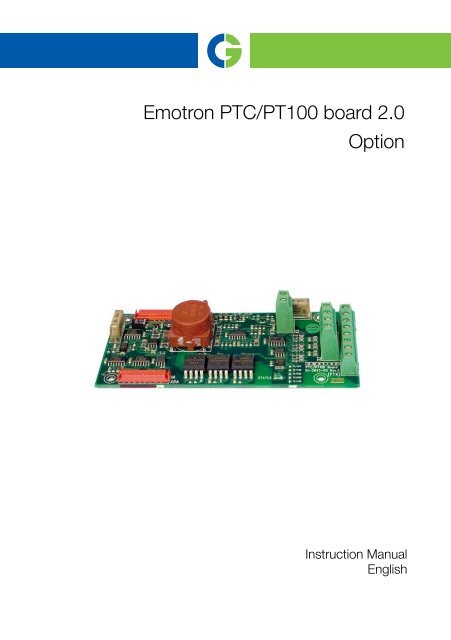
Emotron PTC/PT100 board 2.0 Option
Emotron PTC/PT100 board 2.0 Option
Emotron PTC/PT100 board 2.0 Option
Create successful ePaper yourself
Turn your PDF publications into a flip-book with our unique Google optimized e-Paper software.
<strong>Emotron</strong> <strong>PTC</strong>/<strong>PT100</strong> <strong>board</strong> <strong>2.0</strong><br />
<strong>Option</strong><br />
Instruction Manual<br />
English
<strong>Emotron</strong> <strong>PTC</strong>/<strong>PT100</strong> <strong>board</strong> <strong>2.0</strong><br />
<strong>Option</strong><br />
Instruction Manual - English<br />
Document number: 01-5920-01<br />
Edition: r0<br />
Date of release: 2012-03-01<br />
© Copyright CG Drives & Automation Sweden AB 2011 - 2012<br />
CG Drives & Automation retains the right to change specifications<br />
and illustrations in the text, without prior notification. The<br />
contents of this document may not be copied without the explicit<br />
permission of CG Drives & Automation Sweden AB.
Safety<br />
Instruction manual<br />
Read this instruction manual first!<br />
Since this option is a supplementary part of the AC drive, the user must be<br />
acquainted with the original instruction manual of the AC drive. All safety<br />
instructions, warnings, etc. as mentioned in this instruction manual are to be<br />
known to the user.<br />
Safety instructions<br />
Read the safety instructions in the instruction manual for the AC drive.<br />
Installation<br />
Installation, commissioning, dismounting, making measurements, etc. on the<br />
AC drive may only be carried out by personnel who are technically qualified for<br />
the task. Installation must also be carried out in accordance with the local<br />
standards. Ensure that all necessary safety measures are taken.<br />
WARNING!<br />
Take all necessary safety precautions during installation and<br />
commissioning to prevent personal injuries, e.g. by an<br />
uncontrolled load.<br />
Opening the AC drive<br />
WARNING!<br />
Always switch off the mains supply before opening the AC drive<br />
and wait at least 7 minutes to allow the buffer capacitors to<br />
discharge.<br />
Always take adequate precautions before opening the AC drive, even though the<br />
connections for the control signals and jumpers are isolated from the mains<br />
voltage.<br />
CG Drives & Automation, 01-5920-01r0
CG Drives & Automation, 01-5920-01r0
Contents<br />
1. Introduction ................................................................................ 3<br />
2. Installation.................................................................................. 5<br />
2.1 Polarisation of flat cables .......................................................................... 5<br />
2.2 Mechanical mounting................................................................................. 6<br />
2.2.1 <strong>Option</strong> mounting plate................................................................................ 6<br />
2.3 Mounting the first option <strong>board</strong>................................................................. 8<br />
2.4 Mounting another option <strong>board</strong>.............................................................. 11<br />
3. Connections and functions...................................................... 13<br />
3.1 Board layout............................................................................................. 13<br />
3.2 General information ................................................................................ 14<br />
3.2.1 Menus....................................................................................................... 14<br />
3.2.2 Status LED................................................................................................ 14<br />
3.2.3 Cable recommendations and shielding ................................................. 15<br />
3.2.4 Isolation.................................................................................................... 16<br />
3.3 <strong>PTC</strong> input .................................................................................................. 16<br />
3.3.1 Electrical specification ............................................................................ 17<br />
3.3.2 <strong>PTC</strong> connection example......................................................................... 18<br />
3.4 <strong>PT100</strong> input ............................................................................................. 19<br />
3.4.1 Electrical specifications........................................................................... 20<br />
3.4.2 <strong>PT100</strong> connection example .................................................................... 21<br />
CG Drives & Automation 01-5920-01r0 1
2 CG Drives & Automation 01-5920-01r0
1. Introduction<br />
This <strong>board</strong> is used to connect motor thermistors (<strong>PTC</strong>) acc. to DIN44081/<br />
44082 and/or <strong>PT100</strong> sensors acc. to IEC 60 751 to the main product. Note<br />
that both the <strong>PTC</strong> and the <strong>PT100</strong> sensors needs to be isolated from live voltage,<br />
see § 3.2.4, page 16 for further details.<br />
There are three terminals on the option <strong>board</strong>, X1 - X3. X1 and X2 for <strong>PT100</strong><br />
input and X3 for <strong>PTC</strong> input.<br />
Both <strong>PTC</strong> and <strong>PT100</strong> functions can be used for thermal motor protection.<br />
When the monitored temperature e.g. motor temperature becomes too high,<br />
the VSD will trip. The <strong>PTC</strong> and <strong>PT100</strong> thermal motor protection function is<br />
activated in menu [234].<br />
The <strong>PT100</strong> function can also be used as a process temperature feedback to<br />
optimise the control. This function can be activated in menu [321]. The <strong>PT100</strong><br />
function can also be used for monitoring measured temperatures by the<br />
analogue comparators and the programmable levels. This function can be<br />
activated in menu [611] or [614].<br />
CG Drives & Automation 01-5920-01r0 Introduction 3
4 Introduction CG Drives & Automation 01-5920-01r0
2. Installation<br />
This chapter describes how to mount the option <strong>board</strong> in the AC drive. Up to<br />
three different option <strong>board</strong>s and one communication <strong>board</strong> can be mounted.<br />
2.1 Polarisation of flat cables<br />
The flat cable is marked with colour on one side and has a tap on the<br />
micromatch male contact. This side must be matched to the female micromatch<br />
contact on the control <strong>board</strong> and option <strong>board</strong> respectively, where a small hole<br />
in the <strong>board</strong> is located.<br />
Fig. 1 Polarisation of flat cable<br />
!<br />
CAUTION!<br />
Incorrect connection might cause damage to both the option<br />
and to the control <strong>board</strong>/external equipment.<br />
CG Drives & Automation, 01-5920-01r0 Installation 5
2.2 Mechanical mounting<br />
Make sure that the AC drive has been switched off for at least seven minutes to<br />
ensure that the capacitor bank is discharged before continuing with installation!<br />
Also make sure that no external equipment connected to the drive’s interface is<br />
switched on.<br />
NOTE: Correct installation is essential for fulfilling the EMC requirements<br />
and for proper operation of the module.<br />
2.2.1 <strong>Option</strong> mounting plate<br />
Delivered with the option mounting kit<br />
The option mounting plate must be mounted before any option can be<br />
installed. The mounting plate may already be installed in the main product. In<br />
that case go directly to section 2.3 on page 8 for further mounting instructions.<br />
The option mounting kit consists of the following:<br />
Fig. 2 <strong>Option</strong> mounting kit<br />
Colour marked<br />
• One mounting plate with the slots marked C, 1, 2 and 3.<br />
C = communication option.<br />
• 2 screws<br />
• One 16-pole flat cable for connection to the control <strong>board</strong> when mounting<br />
option <strong>board</strong>s on position 1.<br />
6 Installation CG Drives & Automation, 01-5920-01r0<br />
75 +3 -0
Mounting<br />
1. Make sure that the power supply is switched off for at least 5 minutes before<br />
opening the variable speed drive.<br />
2. Open the door to the variable speed drive.<br />
3. Jack the option mounting plate on to the control <strong>board</strong> mounting plate as<br />
shown in Fig. 3. It can only be turned in one direction.<br />
4. Drag the option mounting plate towards the control <strong>board</strong> until the screw<br />
holes match. Keep the side with the screw holes tilted up slightly until the<br />
RJ45 contact fits into its hole.<br />
NOTE: Be careful not to damage the RJ45 contact (connection for the<br />
control panel), see picture below.<br />
5. Secure the plate with the two screws.<br />
RJ45 contact<br />
Fig. 3 Mounting the option mounting plate on the control <strong>board</strong><br />
CG Drives & Automation, 01-5920-01r0 Installation 7
2.3 Mounting the first option <strong>board</strong><br />
The first option <strong>board</strong> is always mounted on the slot marked 1 on the mounting<br />
plate. In this example we assume that no other option <strong>board</strong> is installed.<br />
Delivered with the option <strong>board</strong> kit<br />
• <strong>Option</strong> <strong>board</strong> and four screws.<br />
• 16-pole flat cable for connection between two option <strong>board</strong>s.<br />
• Insulating sheet.<br />
Mounting<br />
1. Connect the 16-pole flat cable to the X5 connector on the control <strong>board</strong><br />
with the cable downwards as in Fig. 4.<br />
NOTE: The polarisation of the flat cable, see section 2.1 on page 5.<br />
Fig. 4 Flat cable connected to the control <strong>board</strong><br />
8 Installation CG Drives & Automation, 01-5920-01r0
2. Place the insulating sheet over the short spacers on the slot marked 1 on the<br />
mounting plate. Make sure the edge bent upwards is mounted towards the<br />
control <strong>board</strong> interface as in the figure below.<br />
Fig. 5 Mounted insulating sheet<br />
3. Connect the other end of the 16-pole flat cable to the X5A connector on the<br />
option <strong>board</strong>. Make sure that the polarisation is correct as in section 2.1 on<br />
page 5.<br />
NOTE: Connect the micro match male contact to the option in the same<br />
manner as on the control <strong>board</strong>, i.e. the tap on the micro match contact<br />
must be fitted into the hole in the PCB.<br />
CG Drives & Automation, 01-5920-01r0 Installation 9
Fig. 6 Flat cable connected to the option <strong>board</strong><br />
4. Put the option <strong>board</strong> on the spacers.<br />
5. Fasten the <strong>board</strong> using the four screws.<br />
Fig. 7 Mounted option <strong>board</strong><br />
10 Installation CG Drives & Automation, 01-5920-01r0
2.4 Mounting another option <strong>board</strong><br />
1. Place the insulating sheet on the spacers on the option <strong>board</strong> slot marked 2<br />
or 3. It is necessary to select the slot closest to the already mounted option<br />
<strong>board</strong>.<br />
NOTE: Place the insulating sheet with the turned up edge facing the<br />
interface of the control <strong>board</strong> to achieve proper insulation between the<br />
option <strong>board</strong>s.<br />
2. Put the option <strong>board</strong> on the spacers.<br />
3. Fasten the option <strong>board</strong> on the spacers using the four screws.<br />
4. Connect the short flat cable between the X5B connector on the first option<br />
<strong>board</strong> and the X5A connector on the option <strong>board</strong> you have just mounted.<br />
Fig. 8 Two option <strong>board</strong>s mounted on the option mounting plate<br />
CG Drives & Automation, 01-5920-01r0 Installation 11
12 Installation CG Drives & Automation, 01-5920-01r0
3. Connections and functions<br />
3.1 Board layout<br />
IN<br />
X5A<br />
D3<br />
STATUS<br />
X2<br />
11 12 13 14<br />
Fig. 9 <strong>PTC</strong>/<strong>PT100</strong> option <strong>board</strong> layout<br />
21 22<br />
X5B<br />
OUT<br />
CG Drive & Automation 01-5920-01r0 Connections and functions 13<br />
X3<br />
1 2 3 4 5 6 7 8<br />
X1
3.2 General information<br />
3.2.1 Menus<br />
The following menus are available when the <strong>PTC</strong>/<strong>PT100</strong> option <strong>board</strong> is<br />
installed in the main product.<br />
All menus are described in the manual for the main product.<br />
Table 1 Menus available with the <strong>PTC</strong>/<strong>PT100</strong> option <strong>board</strong><br />
Menu Function Default Range/Selection<br />
234<br />
Thermal<br />
protection<br />
Off<br />
235 Motor Class F140<br />
71B <strong>PT100</strong> 1,2,3 -<br />
3.2.2 Status LED<br />
For location of status LED, see Fig. 9.<br />
Table 2 Specification of status LED<br />
D3<br />
LED Specification<br />
Flashing slow (1 Hz) = OK<br />
Flashing fast = communication error<br />
Off = no power supply<br />
Off = No thermal protection<br />
<strong>PTC</strong> = <strong>PTC</strong> protection enabled<br />
<strong>PT100</strong> = <strong>PT100</strong> protection enabled<br />
<strong>PTC</strong>+<strong>PT100</strong> = Both protections enabled<br />
A 100�C, E 115�C, B 120�C, F 140�C,<br />
F Nema 145�C, H 165�C<br />
Shows the measured temperature with<br />
a resolution of 1 degree, for all <strong>PT100</strong><br />
inputs.<br />
14 Connections and functions CG Drives & Automation 01-5920-01r0
3.2.3 Cable recommendations and shielding<br />
Shielded twisted pair cables are recommended. Connect the cable shield firmly<br />
(low ohmic connection) to the mounting plate (PE) according to picture below.<br />
Shield<br />
Fig. 10 General shielding<br />
Signal wires<br />
Mounted option <strong>board</strong><br />
The shield must end at the clamp. Only the signal wires should continue to the<br />
terminals of the <strong>PTC</strong>/<strong>PT100</strong> option <strong>board</strong>.<br />
In most cases it is recommended that both ends of the shield are connected to<br />
PE. This will give a good attenuation of high frequency interference. Shield<br />
connection should be made with the largest possible area.<br />
Make sure that you select a cable of material appropriate for your environment.<br />
Consider ambient temperature, humidity and occurrence of chemical substances<br />
such as oil. Standard copper wire with crossing area of approximately<br />
0.14 - 1.5 mm2 will be sufficient in most cases.<br />
CG Drive & Automation 01-5920-01r0 Connections and functions 15
3.2.4 Isolation<br />
The control <strong>board</strong> in the main product is a Separated Extra Low Voltage (SELV)<br />
circuit. This means that this <strong>board</strong> is safely separated from other circuits that<br />
carry higher voltages and is isolated from earth and protective eart conductors of<br />
other circuits. The <strong>PTC</strong>/<strong>PT100</strong> circuit on this option <strong>board</strong> is separated from<br />
the control <strong>board</strong> SELV circuit with separation rated for:<br />
1. Double insulation when used in drives rated up to 480 VAC.<br />
2. Basic insulation when used in drives rated up to 690 VAC.<br />
It is recommended that the <strong>PTC</strong>/<strong>PT100</strong> sensors are always separated from live<br />
parts with at least basic insulation for the relevant voltage.<br />
WARNING!<br />
For drives rated higher than 480 VAC it is mandatory to have at<br />
least basic insulation from the temperature sensor towards live<br />
voltage.<br />
3.3 <strong>PTC</strong> input<br />
This <strong>PTC</strong> input is for safety reasons isolated from internal supplies and electronics,<br />
see § 3.2.4, page 16 for detailed information. The <strong>PTC</strong> sensor should<br />
be connected to terminal X3. No polarisation is needed. Up to six <strong>PTC</strong> may be<br />
connected in series according to DIN44081/44082.<br />
Table 3 Terminal configuration for <strong>PTC</strong> connection<br />
X3 Name Function<br />
21 T1 <strong>PTC</strong> input<br />
22 T2 <strong>PTC</strong> input<br />
16 Connections and functions CG Drives & Automation 01-5920-01r0
3.3.1 Electrical specification<br />
R [k�]<br />
100<br />
10<br />
2.825<br />
1.500<br />
1<br />
0.1<br />
-20<br />
Fig. 11 Typical <strong>PTC</strong>-curve<br />
T switch<br />
The figure above shows a typical <strong>PTC</strong>-curve. The resistance increases drastically<br />
with the temperature after a certain switch temperature, T switch , which is typically<br />
60 - 120 �C (depending on <strong>PTC</strong> type).<br />
Table 4 Electrical specifications for the <strong>PTC</strong> input<br />
T [�C]<br />
Number of <strong>PTC</strong>s 1 to 6 in series acc. to DIN44081/44082<br />
Trip at 2825 � �10%<br />
Reset at 1500 � �10%<br />
Measurement voltage<br />
UT1-T2 at �Tswitch
3.3.2 <strong>PTC</strong> connection example<br />
Fig. 12 Connecting <strong>PTC</strong><br />
T1<br />
X3:21<br />
T2<br />
X3:22<br />
21 22 X3<br />
L1 L2 L3<br />
Fig. 13 Example of an application with three <strong>PTC</strong> in series.<br />
M<br />
3~<br />
18 Connections and functions CG Drives & Automation 01-5920-01r0
3.4 <strong>PT100</strong> input<br />
The <strong>PT100</strong> input is according to EN60751. Connector X1 and X2 on the<br />
<strong>PTC</strong>/<strong>PT100</strong> option <strong>board</strong> have the following terminal configuration:<br />
Table 5 Terminal configuration for <strong>PT100</strong> input<br />
X1 Name Function<br />
1 Feed_1+ Constant current feed channel 1<br />
2 <strong>PT100</strong>_1+ Positive input for <strong>PT100</strong> channel 1<br />
3 <strong>PT100</strong>_1- Negative input for <strong>PT100</strong> channel 1<br />
4 Feed_1- Constant current feed channel 1<br />
5 Feed_2+ Constant current feed channel 2<br />
6 <strong>PT100</strong>_2+ Positive input for <strong>PT100</strong> channel 2<br />
7 <strong>PT100</strong>_2- Negative input for <strong>PT100</strong> channel 2<br />
8 Feed_2- Constant current feed channel 2<br />
X2 Name Function<br />
11 Feed_3+ Constant current feed channel 3<br />
12 <strong>PT100</strong>_3+ Positive input for <strong>PT100</strong> channel 3<br />
13 <strong>PT100</strong>_3- Negative input for <strong>PT100</strong> channel 3<br />
14 Feed_3- Constant current feed channel 3<br />
NOTE: <strong>PT100</strong> inputs which are are left unconnected will indicate a<br />
temperature of approximately -99 degrees.<br />
CG Drive & Automation 01-5920-01r0 Connections and functions 19
3.4.1 Electrical specifications<br />
<strong>PT100</strong> [�]<br />
175.84<br />
138.50<br />
100.00<br />
0 100 200<br />
Fig. 14 Sketch of the <strong>PT100</strong> resistance/Temperature relationship.<br />
Table 6 Electrical specifications for <strong>PT100</strong> input<br />
Standard EN60751<br />
Temperature range -100�C to +300�C<br />
Accuracy �1% off full scale<br />
Menu [71B] in the main product shows the by the <strong>PT100</strong> element measured<br />
temperature, with a resolution of 1 degree, for all <strong>PT100</strong> inputs.<br />
T [�C�<br />
20 Connections and functions CG Drives & Automation 01-5920-01r0
3.4.2 <strong>PT100</strong> connection example<br />
Three <strong>PT100</strong> channels are available for temperature measurement. All three PT<br />
100 channels (X1, pin 1-8 and X2, pin 11-14) can be used as a 4-wire input<br />
which can be used for precision measurement to avoid errors due to resistance in<br />
connecting wires.<br />
11 12 13 14 X2<br />
1 2 3 4 5 6 7 8 X1<br />
<strong>PT100</strong> sensor<br />
<strong>PT100</strong> sensor<br />
Fig. 15 Connecting <strong>PT100</strong> sensors for 4-wire temperature measurement<br />
NOTE: To achieve proper 4-wire temperature measurement it is important<br />
that Feed_x+ is connected to <strong>PT100</strong>_x+ and Feed_x- is connected to<br />
<strong>PT100</strong>_x-.<br />
CG Drive & Automation 01-5920-01r0 Connections and functions 21
It is also possible to use these 4-wire inputs as a 2-wire input. Then put a jumper<br />
between Feed_x+ and <strong>PT100</strong>_x+ and one between Feed_x- and <strong>PT100</strong>_x-. See<br />
figure below.<br />
1<br />
Feed_1+<br />
<strong>PT100</strong>_1+<br />
<strong>PT100</strong>_1-<br />
Feed_1-<br />
<strong>PT100</strong> sensor<br />
Fig. 16 Using 4-wire input as 2-wire input.<br />
Motor thermal protection<br />
When the <strong>PT100</strong> function is enabled by selecting function <strong>PT100</strong> or<br />
<strong>PTC</strong>+<strong>PT100</strong> in menu [234] and the correct motor class is selected in menu<br />
[235] this <strong>PT100</strong> function will automatically protect the connected motor<br />
against overheating.<br />
Process value<br />
When PT 100 is selected in menu [321], the <strong>PT100</strong> element is used for feedback<br />
of the actual process temperature to establish an optimised temperature<br />
control.<br />
Monitoring<br />
When <strong>PT100</strong>_1, <strong>PT100</strong>_2 or <strong>PT100</strong>_3 is selected as a Comparator Value in<br />
menu [611] or [614] the measured temperature by the concerning <strong>PT100</strong> can<br />
be used to monitor the temperature level. This analogue comparison can activate<br />
a (alarm) signal via Digital Output or Relay. It also can be used to start an<br />
action in combination with the comparator and the Virtual Connections. See<br />
the main product instruction manual for more information.<br />
22 Connections and functions CG Drives & Automation 01-5920-01r0<br />
X1
OCG Drives & Automation Sweden AB<br />
Mörsaregatan 12<br />
Box 222 25<br />
SE-250 24 Helsingborg<br />
Sweden<br />
T +46 42 16 99 00<br />
F +46 42 16 99 49<br />
www.cgglobal.com / www.emotron.com<br />
CG Drives & Automation, 01-5920-01r0, 2012-03-01


