Sliding patio door installation instructions - LowesLink
Sliding patio door installation instructions - LowesLink Sliding patio door installation instructions - LowesLink
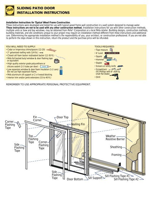
Corner Flashing Tape SLIDING PATIO DOOR INSTALLATION INSTRUCTIONS Installation Instructions for Typical Wood Frame Construction. These instructions were developed and tested for use with typical wood frame wall construction in a wall system designed to manage water. These instructions are not to be used with any other construction method. Installation instructions for use with other construction methods, multiple units or bow and bay windows, may be obtained from Pella ® Corporation or a local Pella retailer. Building designs, construction methods, building materials, and site conditions unique to your project may require an installation method different from these instructions and additional care. Determining the appropriate installation method is the responsibility of you, your architect, or construction professional. If you are not able to perform the steps shown in this instruction, return the product and the purchase price will be refunded. YOU WILL NEED TO SUPPLY: • Cedar or Impervious shims/spacers (12-20) • 2" galvanized roofing nails (1/4 lb.) • Closed cell foam backer rod/sealant backer (12-30 ft.) • Pella foil backed butyl window & door flashing tape or equivalent • High quality exterior grade polyurethane or silicone sealant (2-3 tubes per door) Side Flashing Tape Fin Corner SEALANT SEALANT • Low expansion window & door foam insulation (1-2 cans) Do not use high expansion foams. • Pella aluminum sill support or 2 x 4 wood blocking • Interior trim and/or jamb extensions (15 to 40 ft.) REMEMBER TO USE APPROPRIATE PERSONAL PROTECTIVE EQUIPMENT. Top Flashing Tape Corner Flashing Tape Door Top Side Flashing Tape Nailing Fin Door Bottom TOOLS REQUIRED: • Tape measure • 6' Level • Square • Hammer • Stapler • Scissors or utility knife • Screwdrivers (#2 Phillips with 8" shaft & small flat blade) • Drill Sill Support Weather Resistive Barrier Sheathing Framing Sill Flashing Tape #1 Sill Flashing Tape #2
- Page 2 and 3: 1 ROUGH OPENING PREPARATION A. Veri
- Page 4 and 5: 4INTEGRATING THE DOOR TO THE WEATHE
- Page 6 and 7: 7 SEALING THE DOOR TO THE EXTERIOR
Corner<br />
Flashing<br />
Tape<br />
SLIDING PATIO DOOR<br />
INSTALLATION INSTRUCTIONS<br />
Installation Instructions for Typical Wood Frame Construction.<br />
These <strong>instructions</strong> were developed and tested for use with typical wood frame wall construction in a wall system designed to manage water.<br />
These <strong>instructions</strong> are not to be used with any other construction method. Installation <strong>instructions</strong> for use with other construction methods,<br />
multiple units or bow and bay windows, may be obtained from Pella ® Corporation or a local Pella retailer. Building designs, construction methods,<br />
building materials, and site conditions unique to your project may require an <strong>installation</strong> method different from these <strong>instructions</strong> and additional<br />
care. Determining the appropriate <strong>installation</strong> method is the responsibility of you, your architect, or construction professional. If you are not able<br />
to perform the steps shown in this instruction, return the product and the purchase price will be refunded.<br />
YOU WILL NEED TO SUPPLY:<br />
• Cedar or Impervious shims/spacers (12-20)<br />
• 2" galvanized roofing nails (1/4 lb.)<br />
• Closed cell foam backer rod/sealant backer (12-30 ft.)<br />
• Pella foil backed butyl window & <strong>door</strong> flashing tape<br />
or equivalent<br />
• High quality exterior grade polyurethane or<br />
silicone sealant (2-3 tubes per <strong>door</strong>)<br />
Side<br />
Flashing<br />
Tape<br />
Fin<br />
Corner<br />
SEALANT SEALANT<br />
• Low expansion window & <strong>door</strong> foam insulation (1-2 cans)<br />
Do not use high expansion foams.<br />
• Pella aluminum sill support or 2 x 4 wood blocking<br />
• Interior trim and/or jamb extensions (15 to 40 ft.)<br />
REMEMBER TO USE APPROPRIATE PERSONAL PROTECTIVE EQUIPMENT.<br />
Top<br />
Flashing<br />
Tape Corner<br />
Flashing<br />
Tape<br />
Door Top<br />
Side<br />
Flashing<br />
Tape<br />
Nailing Fin<br />
Door Bottom<br />
TOOLS REQUIRED:<br />
• Tape measure<br />
• 6' Level<br />
• Square<br />
• Hammer<br />
• Stapler<br />
• Scissors or utility knife<br />
• Screwdrivers<br />
(#2 Phillips with 8" shaft &<br />
small flat blade)<br />
• Drill<br />
Sill Support<br />
Weather<br />
Resistive Barrier<br />
Sheathing<br />
Framing<br />
Sill Flashing Tape #1<br />
Sill Flashing Tape #2
1 ROUGH OPENING PREPARATION<br />
A. Verify the opening is plumb and level.<br />
Note: It is critical that the bottom is level.<br />
B. Verify the <strong>door</strong> will fit the opening. Measure all four sides of the opening to make sure it is<br />
3/4" larger than the <strong>door</strong> in width and 1/2" larger in height. Measure the width at the top,<br />
bottom, and center. Measure the height at the far left side, the far right side, and in the center.<br />
Note: 1-1/2" or more of solid wood blocking is required around the perimeter of the<br />
opening. Fix any problems with the rough opening before proceeding.<br />
C. Cut the weather resistive barrier (1C).<br />
1C<br />
Weather Resistive Barrier<br />
1st cut<br />
2nd<br />
cut<br />
3rd cut<br />
4th cut:<br />
Make a 6" cut up from<br />
each top corner at a 45 o<br />
angle to allow the weather<br />
barrier to be lapped over<br />
the fin at the head of the<br />
<strong>door</strong>.<br />
D. Fold the weather resistive barrier (1D). Fold side and bottom flaps into the opening and<br />
staple to inside wall. Fold top flap up and temporarily fasten with flashing tape.<br />
E. Apply sill flashing tape #1. Cut a piece of flashing tape 12" longer than the opening width.<br />
Apply at the bottom of the opening as shown (1E) so it overhangs 1" to the exterior.<br />
Note: The tape is cut 12" longer than the width of the opening so that it will extend up<br />
each side approximately 6".<br />
F. Tab the sill flashing tape and fold. Cut 1" wide tabs at each corner (1/2" from each side of<br />
corner) (1F). Fold tape to the exterior and press firmly to adhere it to the weather resistive<br />
barrier.<br />
G. Apply sill flashing tape #2. Cut a piece of flashing tape 12" longer than the opening width.<br />
Apply at the bottom, overlapping tape #1 by at least 1". Do not allow the tape to extend past<br />
the interior face of the framing (1G).<br />
Note: The flashing tape does not need to extend all the way to the interior of the framing.<br />
H. Attach the aluminum sill support or wood blocking to the exterior of the box plate to<br />
support the edge of the <strong>door</strong> sill. Place the sill support flush with the subfloor.<br />
1"<br />
6"<br />
1F<br />
Interior<br />
1A<br />
Interior<br />
1B<br />
Exterior<br />
1/2"<br />
1"<br />
1D<br />
1/2"<br />
1H<br />
1E<br />
1G
2 PREPARE THE DOOR FOR INSTALLATION<br />
A. Remove the plastic wrap and cardboard packaging from the <strong>door</strong>.<br />
Note: If screens, grilles or hardware are removed from the <strong>door</strong> at this time, label them and store<br />
them in a protected area.<br />
B. Remove the shipping spacers. Carefully slide the movable panel halfway open to remove them.<br />
2 OR MORE PEOPLE WILL BE REQUIRED TO HANDLE THE PANEL SAFELY.<br />
C. Remove the venting panel by lifting it out of the lower track and tilting the bottom of the panel<br />
away from the <strong>door</strong> frame. Then, lower the panel out of the top track. Carefully set the panel aside.<br />
Note: If the fin is not at 90<br />
3 SETTING AND FASTENING THE DOOR<br />
A. Place three 3/8" beads of sealant. The first bead should be approximately 3/4" from the exterior of the rough<br />
opening, the second 2-1/2" in from the first bead of sealant. Place a third bead of sealant in the groove of the sill<br />
support or 1/4" from the exterior edge of the wood blocking.<br />
° D. Fold out <strong>installation</strong> fin to 90<br />
, the <strong>door</strong> will not line up correctly on the interior.<br />
o . Be careful not to remove or tear the fin corners.<br />
2 OR MORE PEOPLE WILL BE REQUIRED FOR THE FOLLOWING STEPS.<br />
B. Insert the <strong>door</strong> from the exterior of the building. DO NOT slide the bottom of the<br />
<strong>door</strong> into the opening. <strong>Sliding</strong> will damage the sealant lines. Place the bottom of the<br />
<strong>door</strong> at the bottom of the opening, then tilt the top into position. Center the <strong>door</strong> between<br />
the sides of the opening to allow equal clearance for shimming, and insert one<br />
roofing nail in the first hole from the corner on each end of the top nailing fin. These<br />
are used to hold the <strong>door</strong> in place while shimming it plumb and square.<br />
C. Plumb and square <strong>door</strong>. Insert shims, as necessary, between the <strong>door</strong><br />
and the sides of the rough opening starting up 6" from the bottom of<br />
the <strong>door</strong>.<br />
Note: DO NOT OVER SHIM.<br />
D. Check the interior reveal. Make sure the measurement from the<br />
interior face of the <strong>door</strong> to the interior face of the wall is equal at<br />
several points around the <strong>door</strong>.<br />
Note: If the dimensions are not equal, check to make sure the<br />
fins are folded out to 90 o at all points.<br />
E. Secure the frame. Insert a 1" wide shim behind the pilot hole at<br />
the lock strike(s). Insert a #8 x 2-1/2" screw (included in the hardware<br />
box) into the pilot hole making sure it passes through the shim<br />
and into the rough opening.<br />
Note: The weather strip must be pushed aside to reveal the pilot<br />
hole. Be careful not to damage the weather strip. Architect Series ® ,<br />
850 Series, and Designer Series ® have 2 lock strikes, ProLine ®<br />
has one lock strike.<br />
F. Fasten the <strong>door</strong> to opening by driving 2" galvanized roofing nails<br />
into each pre-punched hole in the nailing fin.<br />
Note: Make sure the fin corner is lying as flat as possible.<br />
Interior<br />
Fixed Panel 3G<br />
Threshold<br />
3H<br />
3I<br />
Exterior<br />
G. Architect Series & 850 Series: Apply sealant and insert a #8 x 2" screw (provided) into each hole in the bottom of the <strong>door</strong> frame located 1" from<br />
each side (shown above in gold).<br />
H. Architect Series & 850 Series: Position and secure the panel retainer by drilling pilot holes through the remaining 3 holes in the retainer into the<br />
sill support or wood blocking, then apply sealant to the holes and insert a screw into each hole as specified below.<br />
Aluminum sill support: 9/64" pilot holes, #8 x 3/4" thread cutting screws (provided).<br />
Wood blocking: 1/8" pilot holes, #8 x 2-1/2" flat head wood screws (provided).<br />
I. Designer Series OXO: Apply sealant to the holes in the bottom of the <strong>door</strong> frame under the venting panel and insert #8 x 2" screws<br />
(shown above in green).<br />
J. Architect Series & 850 Series - DP 50 applications: Drill a 3/16" pilot hole at each indentation in the extrusion at the top of the <strong>door</strong> frame into<br />
the rough opening. Apply sealant to each hole, then insert a #8 x 3" stainless steel screw into each hole.<br />
shim<br />
3E<br />
Interior<br />
3C<br />
3B<br />
shim<br />
3E<br />
3B<br />
3D<br />
Exterior<br />
3F<br />
mm<br />
1<br />
INCHES<br />
2 3<br />
20 30 40 50 60 70<br />
2D<br />
3A
4INTEGRATING THE DOOR TO THE<br />
WEATHER RESISTIVE BARRIER<br />
A. Apply side flashing tape. Cut 2 pieces of flashing tape 4" longer than the frame height of the <strong>door</strong>.<br />
Apply one piece to each side over the nailing fin and onto the weather resistive barrier. The tape should<br />
extend 2" above the top of the <strong>door</strong> and 2" below the bottom of the <strong>door</strong>. Press the tape down firmly.<br />
B. Apply top flashing tape. Cut a piece of flashing tape long enough to go across the top of the<br />
<strong>door</strong> and extend at least 1" past the side flashing tape on both sides. Apply the tape over the top<br />
nailing fin as shown.<br />
Note: The tape should cover the entire nailing fin, but not extend onto the <strong>door</strong> frame. The<br />
top flashing tape must overlap the side flashing tape to prevent water from getting behind it.<br />
C. Fold down top flap of weather resistive barrier (4C).<br />
D. Apply flashing tape to diagonal cuts. Cut pieces of flashing tape at least 1" longer than the<br />
diagonal cuts in the weather resistive barrier. Apply the tape covering the entire diagonal cut in<br />
the weather resistive barrier at both upper corners of the <strong>door</strong>.<br />
Note: Be sure to overlap the top corners (4D).<br />
5 REINSTALL THE SLIDING PANEL<br />
A. Architect Series & 850 Series: Install the panel clip and screw at the bottom of the sliding<br />
panel on the side opposite the handle.<br />
Note: There is a slot for the clip and a pre-drilled hole for the screw to be inserted into.<br />
2 OR MORE PEOPLE WILL BE REQUIRED TO HANDLE THE PANEL SAFELY.<br />
B. Insert <strong>door</strong> panel. From the exterior of the building, tilt the top of the panel toward the <strong>door</strong><br />
frame and insert the top of the <strong>door</strong> panel into the top track. Move the bottom of the panel<br />
toward the <strong>door</strong> frame until it is vertical. Gently set the panel down into the bottom track.<br />
Architect Series & 850 Series: Adjust the panel clip and tighten the panel clip screw.<br />
Note: Be careful not to pinch your fingers between the two panels. DO NOT close the<br />
sliding panel until you have installed the hardware. The <strong>door</strong> may lock when closed.<br />
C. Install the handles, bumpers, and panel retainer. Follow the <strong>instructions</strong> included in the<br />
hardware box. If the panel is not square to the <strong>door</strong> frame, adjust the bottom rollers by removing<br />
the adjusting hole cover and inserting an 8" long #2 Phillips screwdriver into the hole. Turn clockwise<br />
to raise the panel and counter-clockwise to lower the panel.<br />
D. Architect Series & 850 Series: If the <strong>door</strong> height is greater than 81-1/2", open the vent panel<br />
and locate the large head screw near the interlocker. Turn it counter-clockwise until the vent panel<br />
rubs the head of the screw during operation, then turn the screw one half turn clockwise to allow<br />
the vent panel to operate easily.<br />
E Install screen. Instructions for installing the screen are found in the screen <strong>door</strong> package.<br />
4A<br />
4C<br />
4B<br />
4D<br />
1"<br />
5B<br />
5A<br />
Exterior<br />
Exterior<br />
Exterior<br />
Adjusting hole cover<br />
Screw<br />
Clip
6 INTERIOR<br />
SEAL There are two different methods<br />
for creating an interior seal.<br />
Fiberglass Insulation Method<br />
A. Loosely fill the interior space between the <strong>door</strong> and the rough opening with fiberglass<br />
insulation to within 1" of the interior of the <strong>door</strong> frame.<br />
Note: Packing the insulation too tightly may cause the sides of the <strong>door</strong> to bow.<br />
B. Insert closed cell foam sealant backer rod into the space<br />
to within 1/2" of the interior of the <strong>door</strong> frame.<br />
C. Check the <strong>door</strong> operation by opening and closing the <strong>door</strong>.<br />
Note: If the <strong>door</strong> does not operate correctly, check for plumb,<br />
square and that the sides are not bowed. If the sides are bowed,<br />
remove the backer rod and insulation then adjust shims as<br />
required and repeat the above steps.<br />
I nsulation<br />
1"<br />
Door frame<br />
1/2"<br />
6B<br />
I nsulation<br />
1"<br />
Door frame<br />
6A<br />
Closed cell foam sealant backer rod<br />
D. Apply interior line of sealant over the backer rod. Tool and finish the interior sealant.<br />
Foam Insulation Method<br />
Caution: Ensure use of low expansion polyurethane window and <strong>door</strong> <strong>installation</strong> foams and strictly follow the foam manufacturer's<br />
recommendations for application. Use of high expansive foams or improper application of the foam may cause the <strong>door</strong> to bow and<br />
hinder operation.<br />
A. Apply insulating foam. From the interior, insert the nozzle of the applicator approximately<br />
1" deep into the space between the <strong>door</strong> and the rough opening and apply a 1" deep bead of<br />
foam. This will allow room for expansion of the foam and will minimize squeeze out. Allow<br />
the foam to cure completely (usually 12 to 24 hours) before proceeding to the next step.<br />
Note: Do not completely fill the space from the back of the fin to the interior face of<br />
the opening. Over filling the space may cause the <strong>door</strong> frame to bow.<br />
B. Check the <strong>door</strong> operation by opening and closing the <strong>door</strong>.<br />
Note: If the <strong>door</strong> does not operate correctly, check to make sure it is still plumb, level<br />
and that the sides are not bowed. If the sides are bowed, remove the foam with a serrated<br />
knife and repeat the above steps.<br />
6D<br />
Interior<br />
6A<br />
Interior<br />
6A
7 SEALING<br />
THE DOOR TO THE<br />
EXTERIOR WALL CLADDING<br />
Note: When applying siding, brick veneer or other exterior finish materials, leave adequate space between the <strong>door</strong> frame and the material<br />
for sealant. Refer to the illustration that corresponds to your finish material. Not allowing adequate space and not using backer rod may<br />
cause the sealant to break down prematurely and allow water to infiltrate.<br />
Insulate<br />
and<br />
seal per<br />
Step 4<br />
BRICK VENEER<br />
1/2"<br />
Min.<br />
3/8"<br />
Insulate<br />
and<br />
seal per<br />
Step 4<br />
WOOD<br />
SIDING<br />
Backer Rod and<br />
Sealant typical<br />
3/8" Clearance<br />
Accessory Insulate<br />
Groove and<br />
seal per<br />
Perimeter Sealant Step 4<br />
must extend to room<br />
side of Accessory<br />
Groove.<br />
1/8"<br />
Sealant typical<br />
1/8" Clearance<br />
Accessory<br />
Groove<br />
VINYL/STEEL<br />
SIDING<br />
1/2"<br />
Min.<br />
3/8"<br />
Insulate<br />
and<br />
seal per<br />
Step 4<br />
A. Insert backer rod into the space around the <strong>door</strong> as deep as it will go. This should<br />
provide at least a 1/2" clearance between the backer rod and the exterior face of the <strong>door</strong>.<br />
Note: Backer rod adds shape and depth for the sealant line.<br />
B. Apply a bead of high quality exterior grade sealant to the entire perimeter of the <strong>door</strong>.<br />
Pump extra sealant into the corners of the <strong>door</strong> to fill the cavity deeper than the depth of<br />
the notches. At each end of the bottom of the <strong>door</strong>, insert sealant into the spaces between<br />
the bottom of the <strong>door</strong> and the sill support and connect it to the perimeter sealant.<br />
Note: Filling the corners to the depth of the notch will help prevent water from<br />
penetrating into the cavity.<br />
C. Shape, tool and clean excess sealant. When finished, the sealant should be the shape of<br />
an hourglass.<br />
Note: This method creates a more flexible sealant line capable of expanding and<br />
contracting.<br />
D. Remove plastic guards at the base of the <strong>door</strong> once construction is complete.<br />
Backer Rod and<br />
Sealant typical<br />
3/8" Clearance<br />
Accessory<br />
Groove<br />
Perimeter Sealant<br />
must extend to room<br />
side of Accessory<br />
Groove.<br />
WOOD SIDING<br />
WITH TRIM<br />
1/2"<br />
Min.<br />
3/8"<br />
Sealant typical<br />
3/8" Clearance<br />
Accessory<br />
Groove<br />
Perimeter Sealant<br />
must extend to room<br />
side of Accessory<br />
Groove.<br />
7A<br />
7B
8 INTERIOR FINISHING<br />
Visible wood surfaces of Pella Products must be finished. Failure to do so voids the Limited Warranty. If products cannot be finished immediately,<br />
cover with clear plastic film to protect from dirt, damage and moisture. Remove any construction residue before finishing. Sand all wood surfaces<br />
lightly with 180 grit or finer sandpaper. Do NOT use steel wool. BE CAREFUL NOT TO SCRATCH THE GLASS. Remove sanding dust. If<br />
your window has an interior removable glass panel, remove it and finish the wood between the panes. This may help prevent condensation For<br />
information on types of finish recommended by Pella Corporation, and for other information, see the Pella Owner's Manual or www.pella.com.<br />
Note: To maintain proper product performance do not paint, finish or remove the weather-stripping, mohair dust pads, gaskets or vinyl parts.<br />
Air and water leakage will result if these parts are removed. If paint, stain or finish gets on the mohair weather-stripping, immediately blot it<br />
thoroughly with a rag and allow it to dry. Flake off any remaining residue. After finishing, allow windows to dry completely before closing<br />
them or reinstalling removable glass panels. Pella Designer Series Products have breather holes in the sash which must be clear for maximum<br />
performance. Do not get paint or other finish in the breather holes.<br />
Pella Corporation is not responsible for finishing imperfections. Use of inappropriate finishes, solvents, brickwash or cleaning chemicals will cause<br />
adverse reactions with window and <strong>door</strong> materials and voids the Limited Warranty.<br />
EXTERIOR FINISH<br />
The exterior frame and sash are protected by aluminum cladding with a Pella EnduraClad ® or EnduraClad Plus baked-on factory finish that needs<br />
no painting. Clean this surface with mild soap and water. Stubborn stains and deposits may be removed with mineral spirits. Do NOT use abrasives.<br />
Do NOT scrape or use tools that might damage the surface.<br />
Use of inappropriate finishes, solvents, brickwash or cleaning chemicals will cause adverse reactions with window and <strong>door</strong> materials and voids the<br />
Limited Warranty.<br />
CARE AND MAINTENANCE<br />
Care and maintenance information is available in the Pella Owner's Manual. You can obtain an owner's manual by contacting your local Pella sales<br />
representative. This information is also available at www.pella.com.<br />
IMPORTANT NOTICE<br />
Because all window and <strong>door</strong> systems anticipate some water infiltration, it is important that the wall system be designed and constructed to<br />
properly manage moisture. Pella Corporation is not responsible for claims or damages caused by unanticipated water infiltration; deficiencies in<br />
building design, construction and maintenance; failure to install Pella products in accordance with these <strong>instructions</strong>; or the use of Pella products in<br />
systems which do not allow for proper management of moisture within the wall systems. The determination of the suitability of all building<br />
components, including the use of Pella products, as well as the design and <strong>installation</strong> of flashing and sealing systems are the responsibility of you,<br />
your architect, or a construction professional. Moisture problems, including unacceptable water infiltration, have been associated with barrier<br />
systems, such as EIFS (also known as synthetic stucco). Pella products should not be used in barrier EIFS systems unless Pella's current,<br />
recommended <strong>installation</strong> procedures for <strong>installation</strong> of windows and <strong>door</strong>s into EIFS are used. Any other use of Pella products with barrier EIFS<br />
systems will void the Limited Warranty.<br />
Product modifications that are not approved by Pella Corporation will void the Limited Warranty.<br />
©Pella Corporation 2003 Part Number: 801W0002


