The Next Generation Garage Door Installation & Maintenance - Clopay
The Next Generation Garage Door Installation & Maintenance - Clopay
The Next Generation Garage Door Installation & Maintenance - Clopay

You also want an ePaper? Increase the reach of your titles
YUMPU automatically turns print PDFs into web optimized ePapers that Google loves.
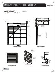
STEP 15 – Attaching an Automatic Opener<br />
IMPORTANT: To avoid damage to your door, you must<br />
reinforce the top section of the door in order to provide a<br />
mounting point for the opener to be attached. Refer to the<br />
section of this manual titled Reinforcing the Top Section on<br />
page 14 for specifi c instructions. Failure to reinforce the door<br />
as illustrated will void the warranty on your door.<br />
WARNING<br />
To avoid risk of strangulation or personal injury to<br />
children, if your door has a pull rope, you must remove<br />
the pull down rope when you install an automatic garage<br />
door opener.<br />
IMPORTANT: When installing an automatic garage door<br />
operator, make sure to follow manufacturer’s installation and<br />
safety instructions carefully. Remove the pull down rope and<br />
unlock or remove the lock. If attaching an operator bracket<br />
to the wooden anchor pad, make sure the wood anchor pad<br />
is free of cracks and splits and is fi rmly attached to the wall.<br />
Always drill pilot holes before attaching lag screws.<br />
<strong>The</strong> operator arm will usually be attached to the vertical<br />
reinforcement member at roughly the same height as the top<br />
roller of the door. Attach the opener arm to the reinforcement<br />
as shown in Figures 15-B to 15-D. To prevent the top of the<br />
door from bending, the opener rail should be mounted no less<br />
than 2" and no greater than 5" from the face of the door with<br />
the door in the open position (FIG. 15-A). Additionally, when<br />
the door is closed, the portion of the operator arm attached to<br />
the door should be at angle of approximately 60 degrees from<br />
the vertical (FIG. 15-B).<br />
18<br />
Opener Arm Attachment To Horizontal Angle Or Strut<br />
Punched<br />
Angle<br />
Punched<br />
Angle<br />
Horizontal<br />
Angle<br />
Or Strut<br />
Opener Arm<br />
Horizontal Angle<br />
Or Strut<br />
Front View (Assembled)<br />
G01-R01-0704<br />
Supplemental<br />
Bracket (Not Available<br />
On All <strong>Door</strong>s)<br />
Opener Arm<br />
Lock <strong>The</strong>se Nuts<br />
Together Securely<br />
FIG. 15-C (<strong>Door</strong>s with odd number of Panels)<br />
Opener Rail Mounting Distance<br />
FIG. 15-A<br />
3/8" x<br />
1-1/2"<br />
Hex Bolt<br />
Opener Arm<br />
Top View<br />
(assembled)<br />
Leave<br />
Clearance<br />
Clevis<br />
Pin<br />
Opener<br />
Arm<br />
Ceiling<br />
Opener Rail<br />
Horizontal Track<br />
Keep Clearance at 2"–5"<br />
60°<br />
FIG. 15-B (<strong>Door</strong>s with supplied Reinforcement Bracket<br />
and Stile in Center of <strong>Door</strong>)<br />
Opener Arm Attachment To Vertical Angle<br />
Horizontal<br />
Punched<br />
Angle<br />
Vertical<br />
Punched<br />
Angle<br />
Mounting<br />
Surface Of<br />
<strong>Door</strong><br />
Vertical Punched<br />
Angle<br />
Lock <strong>The</strong>se<br />
Nuts Together<br />
Securely<br />
FIG. 15-D (<strong>Door</strong>s with Angle Iron Reinforcement<br />
Bracket and Stile in Center of <strong>Door</strong>)<br />
3/8"<br />
Hex Nut