The Next Generation Garage Door Installation & Maintenance - Clopay
The Next Generation Garage Door Installation & Maintenance - Clopay
The Next Generation Garage Door Installation & Maintenance - Clopay

Create successful ePaper yourself
Turn your PDF publications into a flip-book with our unique Google optimized e-Paper software.
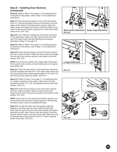
Step 9 – Installing <strong>Door</strong> Sections<br />
(Continued)<br />
Step 9-6: Refer to Table 7-A on page 11. If a reinforcing strut<br />
is required on this section, refer to Step 7-10 for attachment<br />
instructions.<br />
Step 9-7: Place the second section on top of the fi rst section.<br />
Drive a 3” nail into the jambs at each end and bend it over the<br />
edges of the section to hold the section in place. Attach the<br />
roller carriers and hinges from the top of the fi rst section to the<br />
bottom of the second section using two #14 x 5/8” sheet metal<br />
screws each. (FIG. 9-E)<br />
Step 9-8: From Table 9-A, identify the third section and place<br />
on the sawhorses. Install a 03 roller carrier at each end stile<br />
and a 00 hinge at each end stile following the procedure<br />
described in Steps 7-5 through 7-9.<br />
Step 9-9: Refer to Table 7-A on page 11. If a reinforcing strut<br />
is required on this section, refer to Step 7-10 for attachment<br />
instructions.<br />
Step 9-10: Place the third section on top of the other sections<br />
and nail in place as before. Attach the roller carriers and hinges<br />
from the top of the previous section to the bottom of the third<br />
section. (FIG. 9-E)<br />
NOTE: If you have two sections left, repeat steps 9-8 through<br />
9-10 using 04 roller carriers at the end stiles and a 00 hinge at<br />
each center stile.<br />
Step 9-11: Place the last section on the sawhorses. Attach the<br />
top roller brackets with three #14 x 5/8” sheet metal screws into<br />
the pre-punched holes located approximately 3-1/4” and 6-1/4”<br />
from the top of the section as shown. (FIG. 9-F)<br />
Step 9-12: Refer to Table 7-A on page 11. If a reinforcing strut<br />
or L-angle is required on this section, attach above the top<br />
brackets as shown 1/4” x 3/4” self tapping screws at each stile<br />
location. (FIG. 9-F)<br />
Step 9-13: Place the top section on top of the other sections<br />
and nail in place as before. Attach the roller carriers and<br />
hinges from the top of the previous section to the bottom of this<br />
section. (FIG. 9-E)<br />
NOTE: If your door is to be used with an electric operator, you<br />
must reinforce the top section before placing it in the opening.<br />
Proceed to step 10 prior to completing this step.<br />
Step 9-14: Locate the rollers and roller guards. Align the<br />
fl anges on the roller guard as shown with the shaft of the<br />
roller. Slide the guard onto the roller shaft. Repeat roller guard<br />
assembly for each roller. Place a roller with guard in each top<br />
bracket, bottom bracket, and roller carrier tube. Make sure only<br />
the tapered side of the guard fi ts into the “J” hook or tapered<br />
profi le of the track. (FIG. 9-G)<br />
Roller Carrier Attachment Center Hinge Attachment<br />
FIG. 9-E<br />
L-Angle Attachment<br />
FIG. 9-F<br />
FIG. 9-G<br />
P04-R01-0704<br />
13