


Create successful ePaper yourself
Turn your PDF publications into a flip-book with our unique Google optimized e-Paper software.
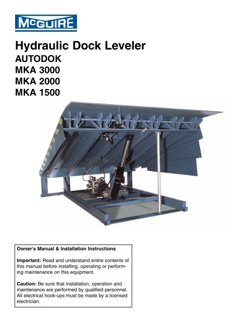
<strong>Hydraulic</strong> <strong>Dock</strong> <strong>Leveler</strong><br />
AUTODOK<br />
MKA 3000<br />
MKA 2000<br />
MKA 1500<br />
Owner's Manual & Installation Instructions<br />
Important: Read and understand entire contents of<br />
this manual before installing, operating or performing<br />
maintenance on this equipment.<br />
Caution: Be sure that installation, operation and<br />
maintenance are performed by qualified personnel.<br />
All electrical hook-ups must be made by a licensed<br />
electrician.
TABLE OF CONTENTS<br />
Introduction ........................................................................................................................................... 1<br />
Overview of Potential Hazards ............................................................................................................ 2<br />
Definition & Function-, Safety Practices .............................................................................................. 3<br />
Installation Instructions ...................................................................................................................... 4-5<br />
Pit Detail & Dimensions ........................................................................................................................ 6<br />
Shim Location Diagram ........................................................................................................................ 7<br />
Electrical Schematics ...................................................................................................................... 8-11<br />
<strong>Dock</strong> Bumper Mounting ...................................................................................................................... 12<br />
Operation Instructions ................................................................................................................... 13-14<br />
Setting the Inspection Leg .................................................................................................................. 15<br />
Maintenance & Service ....................................................................................................................... 16<br />
Trouble Shooting Procedures ............................................................................................................. 18<br />
Control Valves & Motor Pump Adjustments ....................................................................................... 19<br />
Switch Arrangements ......................................................................................................................... 20<br />
<strong>Hydraulic</strong> System View & Parts List .................................................................................................. 21<br />
Control Panel View & Parts List ........................................................................................................ 22<br />
Warranty .............................................................................................................................. Back Cover<br />
INTRODUCTION<br />
Congratulations! You have just purchased one of the industry's finest hydraulically operated dock levelers<br />
from the W.B. <strong>McGuire</strong> Company Inc. of Hudson, NY When properly installed, operated and<br />
serviced, this leveler can offer substantial efficiency and productivity. This <strong>McGuire</strong> hydraulic dock<br />
leveler is the result of many skilled workers and its design, manufacture, and full hydraulic operation<br />
are regarded with pride by the W.B. <strong>McGuire</strong> Company, Inc.<br />
This hydraulic dock leveler by <strong>McGuire</strong> is designed to improve safety and efficiency for personnel<br />
involved in shipping and receiving goods at the loading dock area. Improved safety conditions are<br />
achieved by use of the control panel to operate the dock leveler. This reduces the risk of injury by<br />
keeping personnel off of the leveler and eliminates the unhealthy practice of manually positioning the<br />
leveler. Efficiency is the result of quicker operation, and a more reliable hydraulic operating system.<br />
This system requires minimal maintenance and provides you with years of dependable service.<br />
All safety considerations should be observed by all those who install, operate and service this equipment.<br />
Even well-built products can be installed, operated and serviced in a less than safe manner.<br />
Read this manual completely through to understand all installation, operation and maintenance<br />
instructions and functions before attempting to install, operate or service this hydraulic dock leveler.<br />
Pay special attention to all warnings and/or caution statements.<br />
1
OVERVIEW OF POTENTIAL HAZARDS...<br />
Moving <strong>Leveler</strong><br />
Moving Truck<br />
Moving Shock<br />
!<br />
WARNING<br />
Moving Ramp can cause serious injury or death.<br />
Stay Clear when ramp is in motion.<br />
Do Not enter pit area until ramp has been braced open and<br />
power is turned off and locked out.<br />
Moving Truck can cause serious injury or death.<br />
Stay Clear when truck is in motion.<br />
Do Not stand between truck and ramp when truck is entering<br />
or leaving.<br />
Electrical Shock can cause serious injury or death.<br />
Turn Power Off before touching wires or working in box.<br />
If no power disconnect is provided, station a second person by<br />
the control panel to insure no unauthorized use.<br />
SAFETY INSTRUCTIONS<br />
1. Read manual carefully before installing, operating, or servicing dock leveler.<br />
2. Be sure truck wheels are chocked or truck is held in place by a restraining device before loading or unloading.<br />
3. Make sure leveler is returned to its level, stored position after truck pulls away from dock.<br />
4. Do not attempt to manually lift the dock leveler platform or lip. Do Not operate leveler with equipment, material<br />
or people on the platform, lip or in front of the leveler.<br />
5. Keep pedestrians and forklifts away from open door area when not loading or unloading truck.<br />
6. If dock leveler appears to be broken or is not working properly, contact your authorized <strong>McGuire</strong> representative.<br />
In the following sections the word:<br />
Danger means that serious injury or death will occur from failure to follow instructions.<br />
Warning means that serious injury or death can occur from failure to follow instructions.<br />
Caution means that minor injury or property damage can occur from failure to follow instructions.<br />
Note means that special attention should be given to the instruction.<br />
2
DEFINITION AND FUNCTION<br />
The <strong>McGuire</strong> hydraulic dock leveler is designed for both structural integrity in operation and safety<br />
features for the protection of dock personnel. Its function is to provide a safe and durable bridge<br />
between the building and the trailer. This bridge allows the safe transportation of material handling<br />
devices (i.e. fork truck, pallet jack, hand truck) and workers for the purpose of loading and unloading<br />
the trailer.<br />
All <strong>McGuire</strong> hydraulic levelers are equipped with a velocity fuse "Fail-Safe" system which automatically<br />
halts all motion of the platform, within 1 " to 3", if a truck prematurely departs with a load on the<br />
platform. Other safety features include full-range toe guards that are safety marked, a built-in service<br />
leg support and an automatic night lock feature to aid in the prevention of possible break-in attempts<br />
through the dock area.<br />
The leveler is push button operated from a wall mount control panel and is fully electro-hydraulic<br />
operated. Models can be equipped with an Emergency Stop button which halts all movement of the<br />
leveler at any point during the cycle. A selector switch on the control panel allows automatic positiong<br />
for below dock end load situations.<br />
The unit is powered by a 1 horsepower single or polyphase electric motor with manifold block and a<br />
reservoir that is directly coupled to the motor via the manifold block. The main lift cylinder raises and<br />
lowers the platform. The lip cylinder extends, supports and retracts the lip. Flexible hosing connects<br />
both cylinders to the power unit.<br />
Electrical leads from motor/pump and integral control switches are factory wired, ready to hook up to<br />
leads in the junction box at the rear of the pit. The control panel is wired to work in conjunction with<br />
the motor/pump. Connections between terminals in the control panel and the pit junction box are not<br />
furnished by <strong>McGuire</strong>. This must be done prior to installing this hydraulic leveler. Connections<br />
between terminals in the control panel and the main power line are also not furnished by <strong>McGuire</strong>.<br />
SAFETY PRACTICES<br />
1. Do not operate this equipment while under the influence of drugs or alcohol.<br />
2. Do not stand in the driveway between the leveler and a moving truck.<br />
3. Be sure that the trailer wheels are chocked or restraint device is positioned.<br />
4. Do not use the leveler if appears to be broken or operating improperly.<br />
5. Do not operate the leveler with equipment, material or people on the platform.<br />
6. Be certain that nothing is on the leveler while a truck pulls away from the dock.<br />
7. Keep all limbs clear of the leveler while it is in motion.<br />
8. Do not attempt to manually lift the leveler platform.<br />
9. Always make sure the leveler has been returned to the dock level (stored) position.<br />
10. Never work under the dock leveler without proper placement of the service leg.<br />
11. When servicing leveler, disconnect power and tag control panel "Out of Service."<br />
Place a barrier on grade level in front of the leveler to prevent any truck from backing to the dock.<br />
Contact the <strong>McGuire</strong> Technical Support Team at 1-800-624-8473 if you have any<br />
questions or do not understand any material presented in this manual.<br />
3
INSTALLATION INSTRUCTIONS<br />
CAUTION: Installation must be performed by qualified personnel ONLY.<br />
WARNING: Always support the leveler platform with suitable braces.<br />
NEVER work under the leveler without properly supporting the platform.<br />
Equipment Check:<br />
1. Check the leveler for any possible damage that may have occurred during<br />
transportation. DO NOT INSTALL A DAMAGED LEVELER.<br />
Check that the control panel and bumpers are present. Report any damage<br />
immediately to your supervisor.<br />
Pit Check<br />
2. Check the pit for proper construction. Clean out any debris. Check the pit<br />
walls to make sure they are square and plumb.<br />
3. Measure the pit dimensions to make sure they match the leveler dimensions.<br />
DO NOT INSTALL THE LEVELER IF THE PIT IS NOT FORMED CORRECTLY.<br />
Control Panel<br />
4. Unband the control panel and mount it to the wall where the electrical leads will meet<br />
it. A licensed electrician can now connect the control panel to the main power lead in<br />
and pull the proper leads through conduit and into the junction box at the rear of the<br />
pit. Refer to the proper wiring diagrams (pages 8-11 ) for proper connection.<br />
NOTE.- Factory recommendation is for motor leads to extend from junction box for temporary<br />
power source.<br />
Installation of <strong>Leveler</strong> and Bumpers<br />
5. Move the leveler with a fork truck using the built-in fork slots in the front base frame.<br />
Position the leveler so that the rear frame is approximately 36" from the rear of the pit.<br />
6. A licensed electrician can now connect the temporary extended motor leads from the<br />
junction box to leads in the rubber covered cable from the leveler motor. Refer to<br />
wiring diagram, page<br />
7. Back the fork truck out approximately 24" but keep forks in the slots. Check for proper<br />
wiring by operating the leveler. (See Operation Instructions, pages 13-14).<br />
NOTE- On three phase current, check for proper motor rotation per wiring diagram.<br />
If leveler does not raise when pump is energized, the rotation is wrong. Correct by reversing<br />
two power leads to motor.<br />
8. Once proper operation is achieved, move the leveler to within 12" from the rear of the<br />
pit. The licensed electrician can now make permanent wiring hook-ups and close the<br />
junction box.<br />
4<br />
WARNING: DO NOT enter pit<br />
area until leveler has been braced<br />
open with jack stands.
INSTALLATION INSTRUCTIONS (continued)<br />
9. Position the leveler so that there is 1 " of clearance on both sides. Push the leveler all<br />
the way into the pit, so that the rear frame of the leveler is flush and tight against the rear<br />
curb angle of the pit. Tack weld the leveler to the rear curb angle of the pit at both sides.<br />
10. The fork truck can be removed from the area. Operate the leveler using the control<br />
panel. Raise the platform to its highest position and let the lip extend.<br />
11. Set the built-in inspection leg to help support the platform. The leveler should be sup<br />
ported by suitable braces.<br />
12. Place shims under weight transfer points. See shim location diagram, page The leveler<br />
may have to be stored to check for proper height. The platform should be level with the<br />
dock floor when in stored position. Add or remove shims to make level.<br />
13. Cycle leveler through 5 complete cycles.<br />
14. When all shims are in place and leveler is level with dock floor, finishing welding the<br />
leveler rear angle to the curb angle.<br />
15. Weld shims together and to the base frame of the leveler. At the front, weld shims<br />
together, to the leveler base frame and to the front curb angle of the pit floor.<br />
16. Spot paint front shims and rear angle.<br />
17. Check all hydraulic hoses and fittings for integrity and tightness.<br />
18. Operate leveler and store service leg. Allow leveler to return to stored position , flush<br />
with dock floor.<br />
19. Mount the bumpers to the dock face using suitable fasteners. Bumpers should be at<br />
least 48" from grade measuring to the top of the bumper, and flush with the dock floor.<br />
Mount the inside edge of the bumper flush with the pit side wall.<br />
CAUTION: If the dock floor line is lower than 48", adequate bracing behind the bumpers is<br />
required to maintain the 48" height requirement. Contact factory for specific details.<br />
20. Operate the leveler through several complete cycles. Check for consistent operation.<br />
Check the below dock capability. Check the emergency stop and independent lip<br />
control, if equipped. IF THE LEVELER DOES NOT OPERATE PROPERLY, DO NOT<br />
USE LEVELER. CONTACT McGUIRE IMMEDIATELY.<br />
21. Have an official of your company at the site to review the proper operation<br />
and installation of the dock leveler and sign off the warranty card.<br />
5
PIT DETAILS AND DIMENSIONS...<br />
NOTE: 3" x 3' x 1/4" steel curb angle part 1, 2, 3, & 4 by others. Available by W.B. <strong>McGuire</strong> Co. at additional<br />
cost. Angles must be 1/2” diameter x 6” long steel anchors at 12” max. centers.<br />
6
SHIM LOCATION DIAGRAM<br />
NOTE: The diagram below shows required shim positions to provide proper weight transfer to pit<br />
floor. Shims should be various thicknesses of mild, hot rolled steel. All shims must be tight under<br />
frame, and a minimum of 4"x 4"plate steel. Weld shims in place to assure against movement. Weld<br />
shims together and to leveler base frame as described in the Installation Instructions.<br />
7
ELECTRICAL SCHEMATICS<br />
8
ELECTRICAL SCHEMATICS<br />
9
ELECTRICAL SCHEMATICS<br />
10
ELECTRICAL SCHEMATICS<br />
11
DOCK BUMPER TYPES & MOUNTING INSTRUCTIONS<br />
12
OPERATION INSTRUCTIONS<br />
CAUTION: Be sure that truck wheels are chocked or a restraint device is intact<br />
NOTE- This example control panel is equipped with Emergency Stop and<br />
Independent Lip buttons. This is optional equipment, not standard. MIKA<br />
2000 & MIKA 3000 standard control panels have only the Operate button<br />
and Normal/Below <strong>Dock</strong> selector switch. MIKA 1500 control panels have an<br />
operate button only.<br />
Emergency Stop and Independent Lip operations are covered at the end of<br />
this section.<br />
Example <strong>McGuire</strong> control panel.<br />
NORMAL SETTING ON SELECTOR SWITCH<br />
Loading or unloading with no end load situation.<br />
1. Once the truck has backed against the bumpers, and the wheels have been chocked or a<br />
restraint activated, press and hold the OPERATE button on the control panel until the platform<br />
has raised to the top of its cycle and the lip has been extended.<br />
2. When the lip has fully extended, release the OPERATE button. The platform will lower<br />
smoothly until the lip rests on the truck bed.<br />
3. The leveler will automatically float freely with the rise and fall of the truck bed in either the<br />
loading or unloading cycle.<br />
4. When the truck departs, and the lip becomes unsupported, the leveler will settle to its fully<br />
lowered position. The motor will automatically restart, the leveler will raise just enough to let<br />
the lip fall pendant, and the motor will then automatically shut off. The leveler will settle into its<br />
stored position.<br />
BELOW DOCK SETTING ON SELECTOR SWITCH<br />
Loading or unloading with an end load situation'<br />
1. Once the truck has backed against the bumpers, and the wheels have been chocked or a<br />
restraint activated, press and hold the OPERATE button on the control panel until the platform<br />
has raised to the top of its cycle. The lip will extend far enough to clear the lip keepers. The<br />
motor will automatically shut off and the leveler will smoothly settle into its fully lowered<br />
position.<br />
2. When loading or unloading the end load is finished, return the leveler to the stored, cross<br />
traffic position. If the loading or unloading process needs to be finished under normal<br />
operating circumstances, repeat the steps used under NORMAL SETTING.<br />
13<br />
WARNING: Stay Clear when leveler<br />
or truck is in motion. Do Not stand<br />
between truck and leveler when<br />
truck is entering or leaving.
OPERATION INSTRUCTIONS CONTINUED<br />
OPERATION WITH EXTREMELY LOW TRUCK BEDS<br />
These instructions are intended to be followed when it is necessary to service extremely low trucks<br />
with no end load and the lip must be extended.<br />
1. Once the truck has backed against the bumpers, and the wheels have been chocked<br />
or a restraint activated, set the selector switch to NORMAL, press and hold the<br />
OPERATE button until the platform rises to the top of its cycle and the lip has extended.<br />
2. When the leveler lip has fully extended, release the OPERATE button. The deck will<br />
start to lower with lip extended. Turn the selector switch to BELOW DOCK. The leveler<br />
will settle to its fully lowered position with the lip fully extended.<br />
3. When loading or unloading is finished, return the leveler to the stored, cross<br />
traffic position.<br />
STORING THE LEVELER WITH A TRUCK AT THE DOCK<br />
1. The leveler will be positioned on the bed of the truck.<br />
2. With the selector switch in the NORMAL position, press and hold the OPERATE<br />
button.<br />
3. As the leveler begins to rise, the lip will fall pendant. At this point, release the<br />
OPERATE button and the leveler will return to the stored, cross traffic position.<br />
INDEPENDENT LIP OPERATION (IF EQUIPPED)<br />
1. Once the truck has backed against the bumpers, and the wheels have been chocked<br />
or a restraint activated, set selector switch to NORMAL. Press and hold the OPERATE<br />
button. When the leveler has reached the desired position, release the OPERATE<br />
button and immediately press and hold the LIP EXTEND button.<br />
2. Once the lip has fully extended, release the LIP EXTEND button and deck will settle on<br />
to truck bed with lip extended.<br />
EMERGENCY STOP (IF EQUIPPED)<br />
1. The EMERGENCY STOP button can be pushed at any point of the leveler's cycle to<br />
immediately halt any and all movement of the leveler. Pull the button out to resume<br />
action.<br />
14
OPERATION INSTRUCTIONS CONTINUED<br />
OPERATION WITH EXTREMELY LOW TRUCK BEDS<br />
These instructions are intended to be followed when it is necessary to service extremely low trucks<br />
with no end load and the lip must be extended.<br />
1. Once the truck has backed against the bumpers, and the wheels have been<br />
chocked or a restraint activated, set the selector switch to NORMAL, press<br />
and hold the OPERATE button until the platform rises to the top of its cycle<br />
and the lip has extended.<br />
2. When the leveler lip has fully extended, release the OPERATE button. The<br />
deck will start to lower with lip extended. Turn the selector switch to BELOW<br />
DOCK. The leveler will settle to its fully lowered position with the lip fully<br />
extended.<br />
3. When loading or unloading is finished, return the leveler to the stored, cross<br />
traffic position.<br />
STORING THE LEVELER WITH A TRUCK AT THE DOCK<br />
1. The leveler will be positioned on the bed of the truck.<br />
2. With the selector switch in the NORMAL position, press and hold the<br />
OPERATE button.<br />
3. As the leveler begins to rise, the lip will fall pendant. At this point, release<br />
the OPERATE button and the leveler will return to the stored, cross traffic<br />
position.<br />
INDEPENDENT LIP OPERATION (IF EQUIPPED)<br />
1. Once the truck has backed against the bumpers, and the wheels have been<br />
chocked or a restraint activated, set selector switch to NORMAL. Press and<br />
hold the OPERATE button. When the leveler has reached the desired position<br />
release the OPERATE button and immediately press and hold the LIP<br />
EXTEND button.<br />
2. Once the lip has fully extended, release the LIP EXTEND button and deck<br />
will settle on to truck bed with lip extended.<br />
EMERGENCY STOP (IF EQUIPPED)<br />
1. The EMERGENCY STOP button can be pushed at any point of the leveler's cycle to<br />
immediately halt any and all movement of the leveler. Pull the button out to resume<br />
action.<br />
14
SETTING THE BUILT-IN INSPECTION LEG<br />
The inspection leg is a built-in steel pipe which, when set in place properly, will support the platform<br />
in an upright position. For qualified personnel to perform maintenance or service, the platform should<br />
be supported with adequate bracing. Setting the inspection leg requires two people.<br />
CAUTION: The inspection leg is meant to support the weight of the platform only,<br />
1. Tag the control panel "Out of Service'' to prevent accidental operation of the<br />
leveler.<br />
2. Place barriers on grade level in front of the leveler to prevent trucks from<br />
backing to the dock.<br />
3. Have one attendant raise the leveler platform using the OPERATE button.<br />
Keep the button depressed until the second attendant gives the "OK" to<br />
release.<br />
4. The second attendant can unhook the inspection leg and set it in its vertical position.<br />
Once set, the second attendant can give the "OK" and the first attendant can release<br />
the OPERATE button. As an additional safety measure, press the EMERGENCY STOP<br />
button (if equipped) to cut all power to the leveler.<br />
5. To store the inspection leg, pull the EMERGENCY STOP button (if equipped), press<br />
and hold the OPERATE button until the platform rises to the top of its cycle and the lip<br />
is fully extended. Keep the button depressed until the second attendant gives the "OK"<br />
to release.<br />
6. The second attendant can re-hook the inspection leg to its stored position.<br />
Once set, the second attendant can give the "OK" and the first attendant can<br />
release the OPERATE button. The leveler will return to the stored, cross<br />
traffic position.<br />
NOTE: NEVER WORK UNDER THE LEVELER WITHOUT<br />
PROPERLY SUPPORTING THE PLATFORM WITH ADEQUATE BRACES.<br />
DO NOT PUT ANYTHING ON THE LEVELER PLATFORM WHILE<br />
THE INSPECTION LEG IS SUPPORTING THE PLATFORM.<br />
MAKE SURE CO-WORKERS KNOW NOT TO OPERATE THE LEVELER<br />
WHILE MAINTENANCE OR SERVICE IS BEING PERFORMED.<br />
15<br />
WARNING: DO NOT enter pit area<br />
until leveler has been braced open<br />
with jack stands.
MAINTENANCE AND SERVICE<br />
WARNING: DO NOT enter pit area<br />
until leveler has been braced open<br />
On-site maintenance personnel can observe the following<br />
with jack stands.<br />
procedures or you can arrange for professional service through your authorized <strong>McGuire</strong> representative.<br />
The frequency of maintenance and service required will vary due to the amount and type of usage.<br />
Contact your authorized <strong>McGuire</strong> representative of the factory for information.<br />
Authorization to repair, replace or otherwise adjust any portion of the dock leveler should always be<br />
secured in advance of any work taking place. Failure to do so could VOID the dock leveler warranty.<br />
1. Follow the procedures for Setting the Built-in Inspection Leg.<br />
2. Clean any debris from the pit. Clear the hinge areas of any collected debris. During winter<br />
months in cold climate, remove any ice formed on moving parts.<br />
3. Inspect the condition of lip, platform, subframe and all welds for wear and/or damage. Report<br />
any deficiencies immediately. If in doubt, report it!<br />
4. Check conditions of front and rear hinges. Report any deficiencies.<br />
5. Check the fluid level in the motor/pump reservoir using the dipstick on the breather cap. If<br />
necessary, add proper fluid. Replace the breather cap.<br />
6. Check integrity of ail hydraulic hoses and fittings for tightness. Replace or tighten as needed.<br />
7. Inspect all hydraulic cylinders and switches for damage or wear. Replace as required.<br />
8. Inspect and lubricate all cylinder pivots.<br />
9. Check weatherseals for damage or signs of wear. Replace as required.<br />
10. Inspect toe guards for damage. Replace as required.<br />
11. Inspect all electrical connections and wiring for signs of wear or damage. Report<br />
any deficiencies. Have only a licensed electrician make repairs.<br />
12. Check safety tape markings. Replace as required.<br />
13. Check all labels and warnings. Replace as required.<br />
14. Inspect bumpers for wear. Check fasteners. Tighten, or replace as required.<br />
15. Follow the instructions for storing the service leg.<br />
16. Once leveler is returned to the stored position, operate the leveler following the Operation<br />
Instructions. Run the leveler through several complete cycles. IF LEVELER IS NOT OPERATING<br />
PROPERLY, DO NOT USE THE LEVELER. CONTACT YOUR AUTHORIZED REPRESENTATIVE<br />
OR THE FACTORY IMMEDIATELY.<br />
16
TROUBLE SHOOTING PROCEDURES<br />
If the corrective action does not solve the problem, consult the <strong>McGuire</strong> Technical Support Team<br />
immediately. DO NOT USE THE LEVELER.<br />
If you encounter a problem that is not covered under this section, consult the <strong>McGuire</strong> Technical<br />
Support Team immediately at 1-800-624-8473.<br />
SYMPTON POSSIBLE CAUSE CORRECTIVE ACTION<br />
1. <strong>Leveler</strong> will not rise.<br />
Motor not running.<br />
2. <strong>Leveler</strong> will not rise.<br />
Motor running or humming.<br />
Motor starts then stops.<br />
A. Incorrect or disconnected<br />
electrical hookup.<br />
B. Blown fuses or open circuit<br />
breakers in building.<br />
C. Loss of line voltage.<br />
D. Open overload relays on<br />
leveler motor starter.<br />
E. Burned out motor in leveler<br />
motor/pump.<br />
A. If motor humming (1 phase<br />
current), voltage drop. May be<br />
due to insufficient line capacity.<br />
B. Wrong rotation of 3-phase<br />
motor.<br />
C. Motor is single phasing on<br />
3-phase current.<br />
17<br />
A. Review wiring diagram and<br />
check connections.<br />
B. Check fuses and replace or<br />
reset circuit breakers.<br />
Determine and correct cause<br />
of electrical problems.<br />
C. Check line and repair as<br />
necessary.<br />
D. Allow to cool and reset by<br />
pushing in reset button at the<br />
thermal overload in control<br />
panel.<br />
E. Replace power unit (contact<br />
factory) or have electrical shop<br />
repair motor.<br />
A. Test voltage at motor starter<br />
with motor running. Also test<br />
for amperage draw. Low voltage/high<br />
amperage indicates<br />
wire gauge is too<br />
light for distance of run.<br />
Replace feed line with adequate<br />
wire size.<br />
B. Reverse T1 & T3 hookup at<br />
starter terminal.<br />
C. Check line fuse or other<br />
loss of power in one line.<br />
(Loose connection or tripped<br />
overload at starter.)
TROUBLE SHOOTING PROCEDURES CONTINUED<br />
SYMPTON POSSIBLE CAUSE CORRECTIVE ACTION<br />
3. <strong>Leveler</strong> will not lower. Lip<br />
is extended.<br />
4. <strong>Leveler</strong> continues to<br />
"lockup" after each actuation<br />
of OPERATE button.<br />
5. <strong>Leveler</strong> will not automatically<br />
return from below<br />
dock position. (Not automatic<br />
on MKA 1500 series<br />
levelers.)<br />
6. <strong>Leveler</strong> will not rise.<br />
Selector switch in BELOW<br />
DOCK position.<br />
7. Lip will not hold out; lip<br />
sag occurs.<br />
8. Lip extends too soon.<br />
D. Load on leveler.<br />
E. Low fluid or no fluid.<br />
F. Motor pump is ph sically or<br />
electrically damaged.<br />
G. Overloaded main circuit.<br />
A. Physical obstruction.<br />
B. In "Fail-Safe" lockup.<br />
A. Ramp lowering speed is too<br />
high.<br />
A. Selector switch is in BELOW<br />
DOCK mode.<br />
B. Return switch arm has not<br />
engaged the tripper bolt.<br />
C. Return switch arm may be<br />
out of adjustment or damaged<br />
D. Incorrect wiring or loose.<br />
A. Lip switch arm may be out of<br />
adjustment or damaged.<br />
B. Incorrect or loose wire.<br />
A. Valve maybe clogged.<br />
B. Secondary Relief Valve out<br />
of adjustment.<br />
C. Low voltage - more often<br />
occurs on 1 ph motors.<br />
D. Low fluid.<br />
A. Sequence Valve set too low.<br />
18<br />
D. Remove load to operate<br />
leveler. <strong>Leveler</strong> is not designed to<br />
lift more than its own weight.<br />
E. Check fluid level and fill as<br />
required. Determine and correct<br />
cause of fluid loss.<br />
F. Replace motor/pump.<br />
G. Check current draw.<br />
A. Remove obstruction.<br />
B. Actuate the OPERATE button<br />
momentarily to unlock the "Fail-<br />
Safe" system.<br />
A. Adjust shuttle valve on<br />
motor/pump to reduce ramp lowering<br />
speed.<br />
A. Change selector switch to<br />
NORMAL mode.<br />
B. Adjust tripper bolt to correct<br />
adjustment to trip return switch.<br />
C. Properly position return switch<br />
arm or replace if required.<br />
D. Check wiring/connections.<br />
A. Adjust arm or replace.<br />
B. Check wiring/connections.<br />
A. See lip adjustment section.<br />
B. Adjust valve correctly.<br />
C. Check draw during operation.<br />
Use alternate line.<br />
D. Check level and fill.<br />
A. Adjust sequence valve so lip<br />
extends when dock is fully open.
CONTROL VALVES AND MOTOR PUMP ADJUSTMENT<br />
<strong>McGuire</strong> hydraulic levelers are shipped only after thorough testing and adjustment. They are shipped<br />
ready to install. Control valve adjustments are not normally required and valves should not be adjusted<br />
except to alleviate definite malfunctions.<br />
CONTROL VALVES are cartridge type with cartridges arranged about a valve manifold block. To<br />
avoid disturbing a cartridge, a wrench should be used to secure shoulder of cartridge while adjusting-screw<br />
cap is being removed. Adjusting-screw caps are sealed to cartridge body with a metal ring<br />
gasket. Take caution against damaging or losing this ring as it must be replaced to avoid leakage.<br />
SEQUENCE VALVE controls the timing of lip out-swing. Remove cap and turn adjusting-screw "out"<br />
(counterclockwise) to cause out-swing to begin sooner. Turning screw "in" (clockwise) will delay the<br />
beginning of lip out-swing.<br />
SECONDARY RELIEF VALVE controls hold-out of lip. Turning screw "out" will decrease lip holdout.<br />
However, turning screw too far out will cause lip to sag. If lip "sags," screw must be turned "in" a little<br />
at a time until the lip remains extended. Turning screw "in" too far will excessively increase lip holdout<br />
pressure and will defeat the ability of lip to yield under impact.<br />
SHUTTLE VALVE controls the lowering speed of the main platform. Turning screw "in" will decrease<br />
the rate of descent. Turning screw "out" will increase rate of descent. This valve should not require<br />
field adjustment.<br />
PRIMARY RELIEF VALVE regulates pump pressure. Turning adjusting screw "in" increases pump<br />
pressure. Turning screw "out" will decrease pressure. This valve should not require field adjustment.<br />
Contact factory before attempting to make pressure adjustment.<br />
19
SWITCH ARRANGEMENTS<br />
20
HYDRAULIC SYSTEM VIEW AND PARTS LIST<br />
21
CONTROL PANEL VIEW AND PARTS LIST<br />
22
W.B. McGUIRE COMPANY, INC.<br />
<strong>Hydraulic</strong> <strong>Dock</strong> <strong>Leveler</strong> Warranty<br />
The W.B. <strong>McGuire</strong> Company, Inc. warrants that its hydraulic dock leveler (see models below) will be<br />
free from defects in materials and workmanship under normal use and service for the time period<br />
described below, depending on model, effective from the date of installation. This warranty covers<br />
parts and labor.<br />
<strong>McGuire</strong>'s sole obligation under this warranty is limited to repairing or replacing any part which shall<br />
be determined by <strong>McGuire</strong> to be defective, and is conditioned upon the buyer giving written notice of<br />
any such defect within the warranty period. If <strong>McGuire</strong> concludes that repair or replacement is necessary,<br />
work will commence within a reasonable time period after the decision to repair or replace<br />
has been made.<br />
This warranty will not apply to any product which has been altered, modified, damaged or which has<br />
deteriorated due to abuse, neglect, misuse or by accident. Warranty will be VOID if any repairs are<br />
made or attempted to be made by any person not authorized by <strong>McGuire</strong>. Proper application, installation,<br />
maintenance and operation are required to keep warranty in force.<br />
<strong>Hydraulic</strong> systems are factory preset. Periodic maintenance and adjustment is the sole responsibility<br />
of the owner.<br />
This warranty is <strong>McGuire</strong>'s exclusive expressed warranty. Warranty is limited to value of components<br />
only. <strong>McGuire</strong> assumes no liability for loss of the use of any equipment and expressly disclaims any<br />
liability for incidental or consequential damages. Warranties implied by law are limited in duration to<br />
the five year period described above.<br />
One Hudson Ave.<br />
Hudson, NY 12534<br />
1-800-624-8473<br />
518-828-7652 • Fax: 518-828-1262<br />
www.wbmcguire.com<br />
Models covered by this warranty:<br />
M-Series (5 years)<br />
MKA 1300 (1 year)<br />
MKA 1000HD & MKA 1000LB (1 year)<br />
Represented in This Area By:<br />
The specifications described herein were in effect at the time of printing. However, W.B. <strong>McGuire</strong> Company, Inc. reserves the right to change<br />
specifications and designs or to discontinue models at any time without incurring obligation.<br />
HYDLEV/31-5-1 Go back to Main Page PRINTED IN U.S.A.
