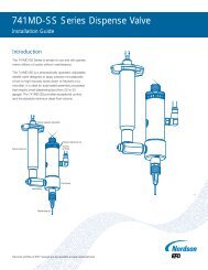
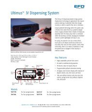
736HPA Installation Guide - Nordson EFD
736HPA Installation Guide - Nordson EFD
736HPA Installation Guide - Nordson EFD

You also want an ePaper? Increase the reach of your titles
YUMPU automatically turns print PDFs into web optimized ePapers that Google loves.
<strong>736HPA</strong> High Pressure<br />
Dispense Valve<br />
INSTALLATION GUIDE<br />
Electronic pdf files of <strong>EFD</strong> manuals are also available at<br />
www.efd-inc.com/manuals.html.<br />
USA & Canada: 800-556-3484 or +1-401-434-1680<br />
Europe: 0800 585733 or +44 (0) 1582 666334<br />
Asia: +86 (21) 5854 2345<br />
technical@efd-inc.com www.efd-inc.com<br />
Introduction<br />
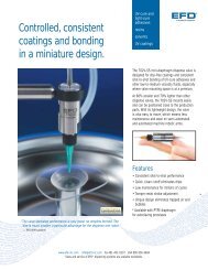
The <strong>736HPA</strong> is a normally closed, air-actuated, balanced<br />
spool-type valve designed to operate at fluid pressures<br />
up to 2,500 psi (172 bar). Ideal for consistent dispensing<br />
of industrial sealants and greases, the <strong>736HPA</strong> valve is<br />
simple to use and will operate many millions of cycles<br />
without wear or leakage.<br />
Fluid supply line<br />
Fluid inlet fitting<br />
Dispensing tip<br />
Control air hose<br />
Air cylinder<br />
body<br />
A NORDSON COMPANY<br />
®<br />
TM
<strong>Installation</strong><br />
Prior to installing this valve, please read<br />
the associated reservoir and valve<br />
controller operating instructions to<br />
become familiar with the operation of all<br />
components of the dispensing system.<br />
1. Thread the fluid inlet fitting into the fluid<br />
inlet hole. Note: The fluid inlet fitting and<br />
hose must be obtained from the high<br />
pressure pump supplier. Ensure that the<br />
hose and fitting are rated for the maximum<br />
operating pressure of the pump system.<br />
fi<br />
To Rhino pump system<br />
(order separately)<br />
Consult <strong>EFD</strong> for Rhino<br />
pump recommendation<br />
2. Connect the fluid feed hose to the fitting.<br />
3. Connect valve control air hose to<br />
ValveMate 8000 (solenoid pack) controller<br />
used to control valve open-time.<br />
4. Install appropriate threaded nozzle to<br />
the valve output or use a dispensing tip<br />
adapter (#2186) with <strong>EFD</strong> SafetyLok <br />
dispensing tips.<br />
5. Check to be sure all fluid and air<br />
connections are tight.<br />
<strong>EFD</strong> <strong>736HPA</strong><br />
6. Make sure valve operating pressure is<br />
set at 70 psi (4.8 bar).<br />
7. Be sure delivery pump pressure does not<br />
exceed 2,500 psi (172 bar).<br />
8. Place a cup under the dispensing tip or<br />
nozzle and actuate the valve until fluid<br />
flows steady.<br />
9. Set desired flow rate by adjusting fluid<br />
pressure or changing the outlet tip size.<br />
Important Note: Set desired deposit size by adjusting valve open time. Refer to valve controller operating manual.<br />
1<br />
2<br />
1 1<br />
4<br />
<strong>EFD</strong> <strong>736HPA</strong><br />
3<br />
8
How the Valve Operates<br />
When air pressure at 70 psi (4.8 bar) is applied, the piston shifts the<br />
spool ➀ to the open position, allowing fluid to flow. At the end of the<br />
cycle, spring force on the piston ➁ shifts the spool to the closed<br />
position, stopping fluid flow. During the closing action, the <strong>736HPA</strong><br />
provides snuff-back of fluid for clean cutoff.<br />
The stroke adjustment ➂ can be used to regulate snuff-back to an<br />
amount appropriate for the fluid being dispensed. Stroke adjustment<br />
can also be used to reduce fluid surge when the valve opens to ensure<br />
consistent bead widths and dot profiles. The stroke is adjusted by<br />
moving the stroke limit stop:<br />
1. To access the stop, first remove the air input hose from the push-in<br />
air coupling by pushing down on the release ring while pulling up<br />
on the tubing.<br />
2. Insert the 1/8” Allen wrench through the air coupling and engage<br />
the stroke limit stop.<br />
3. Adjust the stop toward or away from the piston to vary the stroke.<br />
To decrease the amount of opening surge and closing snuff-back,<br />
extend the limit stop by turning the wrench clockwise. To increase<br />
the amount of surge and snuff-back, retract the limit stop by<br />
turning the wrench counterclockwise.<br />
Note: Adjusting the stroke does not affect the flow rate.<br />
4. Install the air input hose by pushing the hose into the coupling.<br />
Note: For striping applications, fluid surge can be reduced further by<br />
lowering the valve operating air pressure down to, but not below,<br />
40 psi (2.7 bar).<br />
When dispensing very thick fluids at high cycle rates, the double-acting<br />
feature ensures rapid closure. A double-actuating air input ➃ is provided<br />
on the side of the air cylinder to allow double-acting operation using air<br />
pressure to both open and close the valve.<br />
The amount of fluid dispensed is determined by valve open-time, fluid<br />
pressure, dispensing tip size and fluid viscosity.<br />
open closed<br />
www.efd-inc.com technical@efd-inc.com USA 800-556-3484 Europe +44 (0) 1582 666334 Asia +86 (21) 5854 2345<br />
➂<br />
➁<br />
➃<br />
➀
Specifications<br />
General<br />
Size: 116.1 mm length x 34.9 mm diameter<br />
(4.57” x 1.375” )<br />
Weight: 18.9 oz (537 grams)<br />
Air cylinder body: Type 303 stainless steel<br />
Fluid body and cap: Type 303 stainless steel<br />
Fluid inlet thread: 1/4 NPT female<br />
Output thread: 1/4 NPT female<br />
Piston: Hard-coated aluminum<br />
Spool: Hardened stainless, hard-chrome coated<br />
Spool seals: Hytrel ® (Viton ® optional)<br />
Air pressure required: 70 psi (4.8 bar)<br />
Maximum fluid pressure: 2,500 psi (172 bar)<br />
Mounting hole: 5/16-24 UNF tapped hole or<br />
adjustable mounting block<br />
For consistent dispense valve operation and easy adjustment<br />
of valve output, <strong>EFD</strong> recommends using the ValveMate 8000<br />
controller on all automatic, semi-automatic and benchtop<br />
applications.<br />
The <strong>EFD</strong> Ultra TT Series positioning systems incorporate<br />
dispensing control into the main system.<br />
Contact the <strong>EFD</strong> Dispense Valve Systems Group for details.<br />
ValveMate Concept<br />
The ValveMate 8000 provides easy adjustment of valve<br />
output for maximum end-user convenience and efficiency.<br />
Valve open time is the primary control of deposit. The 8000<br />
puts push-button adjustment of valve open time where it<br />
needs to be—at the valve.<br />
The ValeMate 8000 features micro-processor circuity for<br />
extremely precise control of deposit size. Feed lines can be<br />
purged, initial deposit sizes set, and adjustments made<br />
quickly and easily at the dispensing station, without<br />
stopping the production line.<br />
Note: The <strong>EFD</strong> Ultra ® TT 325 and 525 XYZ automated<br />
dispensing systems have integrated ValveMate controllers<br />
for operating all <strong>EFD</strong> dispense valves.<br />
Important Note: Order your 1, 2, 3 or 4 solenoid<br />
manifold block assembly separately. Consult <strong>EFD</strong><br />
for recommendations.<br />
A NORDSON COMPANY<br />
For <strong>EFD</strong> sales and service in over 30 countries,<br />
contact <strong>EFD</strong> or go to www.efd-inc.com/contact<br />
<strong>EFD</strong>, Inc.<br />
East Providence, RI USA<br />
USA & Canada: 800-556-3484; +1-401-434-1680<br />
info@efd-inc.com www.efd-inc.com<br />
<strong>EFD</strong> International Inc.<br />
Dunstable, Bedfordshire, UK<br />
0800 585733 or +44 (0) 1582 666334<br />
Ireland 00800 8272 9444<br />
europe@efd-inc.com www.efd-inc.com<br />
<strong>EFD</strong>, Inc., Asia<br />
China: +86 (21) 5854 2345<br />
china@efd-inc.com www.efd-inc.com/cn<br />
Singapore: +65 6796 9630 sin-mal@efd-inc.com<br />
Hytrel and Viton are registered trademarks of DuPont.<br />
©2007 <strong>Nordson</strong> Corporation 736-INSTALL-01 v060607<br />
®