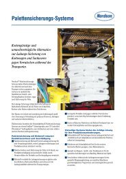
Dispensing Underfill as a Standard Manufacturing Process
Dispensing Underfill as a Standard Manufacturing Process
Dispensing Underfill as a Standard Manufacturing Process

Create successful ePaper yourself
Turn your PDF publications into a flip-book with our unique Google optimized e-Paper software.
PARADIGM SHIFT IN APPLYING UNDERFILL<br />
ABSTRACT<br />
The new advance in applying underfill by utilizing jetting<br />
techniques enables the use of more flip chip die sizes in<br />
compact packages. Jetting underfill <strong>as</strong> well <strong>as</strong> other<br />
semiconductor packaging fluids is a paradigm shift in the<br />
method of applying adhesives versus traditional needle<br />
dispensing. In the p<strong>as</strong>t many types of pumps were used to<br />
dispense fluids but the common denominator w<strong>as</strong> pushing<br />
fluid through a dispensing needle. Jetting eliminates the use<br />
of needles, thereby solving all needle related problems and<br />
opens new innovative techniques to apply adhesives. Also,<br />
new ide<strong>as</strong> for underfilling large flip chips, making zero (0)<br />
width fillets if desired are available if designers are willing<br />
to think differently about package design. This paper will<br />
cover the new theory and process of jetting capillary and noflow<br />
underfill, a new underfill method for large die which<br />
minimizes flow out time, and a review of the b<strong>as</strong>ics of<br />
underfilling. Keywords: Jet, <strong>Underfill</strong>, <strong>Dispensing</strong>, Flip<br />
Chip<br />
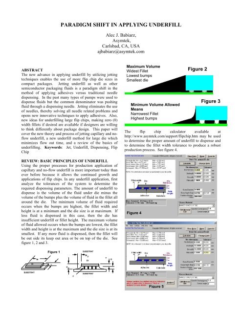
REVIEW: BASIC PRINCIPLES OF UNDERFILL<br />
Using the proper processes for production application of<br />
capillary and no-flow underfill is more important today than<br />
ever before because it allows the continued growth and<br />
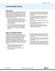
applications of flip chips. In any underfill application, first<br />
analyze the tolerances of the system to determine the<br />
required dispensing parameters. The amount of underfill to<br />
dispense is the volume of the fluid under die minus the<br />
volume of the bumps plus the volume of fluid in the fillet all<br />
around the die. The minimum volume of fluid required<br />
occurs when the bumps are highest, the fillet width and<br />
height is at a minimum and the die size is at maximum. If<br />
less fluid is dispensed in this c<strong>as</strong>e, then the die h<strong>as</strong><br />
insufficient underfill or fillet height. The maximum volume<br />
of fluid allowed occurs when the bumps are lowest, the fillet<br />
width and height is at the maximum and the die size is at its<br />
smallest. If any more fluid is dispensed, then the fillet will<br />
be out side its keep out area or be on top of the die. See<br />
figure 1, 2 and 3.<br />
DI<br />
SUBSTRAT<br />
W<br />
Figure 1<br />
L<br />
H F<br />
I/<br />
SUBSTRAT<br />
W F<br />
DI<br />
SUBSTRAT<br />
Alec J. Babiarz,<br />
Asymtek,<br />
Carlsbad, CA, USA<br />
ajbabiarz@<strong>as</strong>ymtek.com<br />
T<br />
G<br />
Maximum Volume<br />
Widest Fillet<br />
Lowest bumps<br />
Smallest die<br />
Minimum Volume Allowed<br />
Means<br />
Narrowest Fillet<br />
Highest bumps<br />
Figure 3<br />
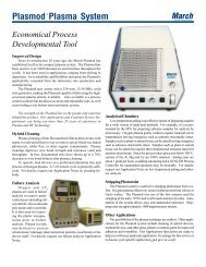
The flip chip calculator available at<br />
http://www.<strong>as</strong>ymtek.com/support/flipchip.htm may be used<br />
to determine the proper amount of underfill to dispense and<br />
to determine the fillet width tolerance to produce a robust<br />
production process. See figure 4.<br />
Figure 4<br />
Figure 5<br />
Figure 2
As an example, if the die h<strong>as</strong> the tolerances shown in figure<br />
5, the required dispense volume would be 20.1mg with a<br />
negative +-5.9%, which is not possible. Since the fillet size<br />
w<strong>as</strong> limited to 1.5 +-0.2mm, the production process is not<br />
viable. The limits on fillet size produced a situation where<br />
the minimum volume of fluid necessary to underfill the die<br />
in one extreme c<strong>as</strong>e is larger than the maximum allowable.<br />
(i.e. the c<strong>as</strong>e of shortest bumps, maximum allowed fillet<br />
size). Therefore, even if the dispensing machine had perfect<br />
accuracy, the underfill process would not work. To correct<br />
the process, incre<strong>as</strong>e the fillet size variation, or gain higher<br />
tolerances on the die.<br />
The flow out time equations for capillary and pressurized<br />
T = Time in seconds<br />
µ = Fluid viscosity<br />
L = Flow distance<br />
h = Gap or bump height<br />
θ = Contact or wetting angle<br />
γ = Surface tension of liquid<br />
. vapor interface<br />
Figure 6<br />
T=(3µL 2 )/(hγcosθ)<br />
Capillary Flow out time<br />
L<br />
µ , γ Ο<br />
h<br />
T = Time in seconds<br />
µ = Fluid viscosity<br />
L = Flow distance<br />
h = Gap or bump height<br />
P = Pressure<br />
P a<br />
Figure 7<br />
µ<br />
underfilling are shown in figures 6 and 7.<br />
The changes in gap (h) under the die affect the flow out<br />
speed and wave front <strong>as</strong> much <strong>as</strong> the bump distribution. As<br />
the fluid flows around bumps, stagnation zones appear <strong>as</strong><br />
the<br />
underfill flows to the<br />
other side of the die. The use of<br />
two<br />
colors of underfill and gl<strong>as</strong>s die reveal a lot about the<br />
flow patterns.<br />
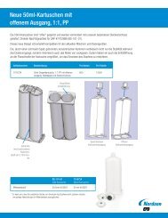
The most commonly accepted dispense patterns are the “I”<br />
and “L” p<strong>as</strong>ses. See figure 8. The “L” p<strong>as</strong>s will typically<br />
provide f<strong>as</strong>ter underfill than the “I” p<strong>as</strong>s by the square root<br />
two.<br />
t = 2<br />
⋅t −<br />
L<br />
Line L shape<br />
The<br />
difference in speed, knit lines and stagnation zones are<br />
apparent in the following photographs<br />
shown in Figure 8.<br />
t<br />
Pressure Forced flow out time<br />
2<br />
6⋅µ<br />
⋅L<br />
bg χ =<br />
= L Pv − Pa ⋅h 2<br />
χ b g<br />
h<br />
P v<br />
I P<strong>as</strong>s<br />
L P<strong>as</strong>s<br />
Knit Line<br />
L P<strong>as</strong>s<br />
Stagnation Zones<br />
The<br />
streaks and flow lines shown in many x-ray and<br />
ultr<strong>as</strong>ound images may be attributed to the<br />
regular<br />
flow of<br />
underfill <strong>as</strong> it works its way through the maze of bumps and<br />
channels under the die in a similar manner<br />
<strong>as</strong> fluid flow<br />
occurs in a much more macro manner in nature. See figure<br />
9.<br />
U P<strong>as</strong>s<br />
Figure 9<br />
I P<strong>as</strong>s<br />
The “L” or “ I” p<strong>as</strong>s may be dispensed in one p<strong>as</strong>s or<br />
multiple p<strong>as</strong>ses. Multiple p<strong>as</strong>ses are used to minimize the<br />
residual wet out area. If all of the material is dispensed<br />
along the die at once, the initial amount of material may<br />
spread on top of the die or to are<strong>as</strong> away from the die. As<br />
the<br />
material wicks under the die, a residual is left behind. If<br />
½ of the material is initially applied, then the wetted filet<br />
area is less and less residual remains after the first p<strong>as</strong>s of<br />
material flows under the die. Most applications require that<br />
the automated dispenser go back to the die to place the next<br />
p<strong>as</strong>s after a certain time. After the required underfill flows<br />
under the die, a final “seal” p<strong>as</strong>s may be applied to make the<br />
fillet even around the die. Bubbles under the die are rarely<br />
caused by application of the underfill. In most c<strong>as</strong>es the<br />
root cause of bubbles is improper substrate baking, excess<br />
flux, or inadequate flux cleaning.<br />
The application of no-flow underfill is very similar to the<br />
application of die attaché adhesives. The material<br />
application in a star pattern allows the air to be flushed out<br />
<strong>as</strong> the die is placed. The challenge for no flow underfill<br />
remains in the epoxy chemistry. Most no flow underfill<br />
epoxies<br />
have less filler, therefore the modulus is lower and<br />
reliability is less. However, there are low I/O applications<br />
where no-flow underfilling is an excellent choice. The noflow<br />
application h<strong>as</strong> a throughput advantage over capillary<br />
underfill when the die placement time or other <strong>as</strong>sembly<br />
processes are not the bottle neck.<br />
PARADIGM SHIFT IN APPLYING UNDERFILL<br />
Applying capillary or no-flow underfill h<strong>as</strong> been<br />
accomplished by using automated needle dispensing<br />
processes. As in any new <strong>as</strong>sembly technology, a series of<br />
problems and innovative solutions have<br />
occurred to allow<br />
viable<br />
production processes for underfilling. The use of<br />
jetting technology for applying underfill instead of needles<br />
brings a change in technology similar to the introduction of<br />
ink jet versus pin printing years ago.
NEEDLE DISPENSING VS. JETTING<br />
Table 1<br />
Problem Needle Jet<br />
Die Clipping<br />
(chipping die<br />
with needle<br />
Maintain<br />
dispense gap<br />
below die and<br />
above substrate<br />
Make small<br />
fillets<br />
Dripping<br />
material on die<br />
and product<br />
Volume<br />
variation die to<br />
die due to<br />
needle to<br />
substrate height<br />
variations on<br />
first line.<br />
Inaccurate<br />
placement due<br />
to bent needles<br />
Inaccurate<br />
placement due<br />
to residual<br />
material on<br />
needle bi<strong>as</strong>es<br />
fluid flow from<br />
needle.<br />
Die spacing<br />
under 1 mm.<br />
Keep out area<br />
near die to<br />
minimize<br />
siphoning UF<br />
away from die.<br />
Maintain high<br />
dispense volume<br />
accuracy<br />
1. Higher needle<br />
placement<br />
accuracy<br />
2. Bent needle<br />
detection<br />
3. Fiducial find at<br />
each die.<br />
Height sense at<br />
each die.<br />
Use small needles.<br />
(requires low flow<br />
rate, therefore low<br />
throughput.)<br />
Shut off valves<br />
close to needle<br />
hub.<br />
1. Height sense at<br />
each die.<br />
2. Minimize<br />
residual material<br />
on needle.<br />
1. Needle sensing<br />
2. Bent needle<br />
detection<br />
Needle cleaners<br />
and wipers<br />
1 Minimum<br />
spacing is needle<br />
outside diameter<br />
+- placement<br />
accuracy.<br />
2. Small needles<br />
(27 gage) limit<br />
flow rate to 1<br />
mg/sec<br />
Clipping is not<br />
possible because<br />
jet is above die.<br />
Height sense only<br />
once per product<br />
because height<br />
tolerance is +- 1<br />
mm.<br />
100u stream size at<br />
30mg/sec flow<br />
rates allows the<br />
smallest fillets in<br />
the industry.<br />
Positive zero (0)<br />
volume shut off at<br />
nozzle for no<br />
dripping.<br />
The amount of<br />
material jetted<br />
does not depend<br />
on distance to<br />
surface.<br />
There is no needle<br />
to bend.<br />
There is no needle<br />
to bi<strong>as</strong> fluid break<br />
off.<br />
1. Minimum<br />
spacing is 100u<br />
stream size +-<br />
placement<br />
accuracy.<br />
2. 30mg/sec flow<br />
rate is possible at<br />
minimum stream<br />
size.<br />
Small needles Small stream size<br />
Utilize positive<br />
displacement<br />
pumps<br />
1. Discrete jetting<br />
of dots <strong>as</strong> small <strong>as</strong><br />
3.5nano liters per<br />
M<strong>as</strong>s flow control<br />
(MFC)<br />
dot.<br />
2. Calibrated<br />
process jetting<br />
allows a m<strong>as</strong>s of<br />
material to be<br />
automatically<br />
jetted <strong>as</strong> a series of<br />
dots in a jet on the<br />
fly line. (MFC for<br />
Jetting)<br />
Table 1 describes the traditional problems related to<br />
automated needle dispensing for underfill and how jetting<br />
technology inherently eliminates the problem or the problem<br />
is mitigated by another process control. One particular<br />
advantage of the jet that is significant for packaging is the<br />
small stream size. Since the jet can apply material in<br />
smaller spaces, designers can package die closer together.<br />
100<br />
microns<br />
There are several types of jet technologies available in the<br />
market. Piezo, pressure, thermal, and continuous flow jets<br />
are limited to low viscosity materials. See Figure 10. The<br />
mechanical jet imparts high energy to a small volume of<br />
material that allows jetting high viscosity materials. The<br />
typical viscosity range of the mechanical jet is 300 cps to<br />
900,000 cps. See Figure 11.<br />
Piezo Jet<br />
Jet Nozzle 30 gage<br />
needle<br />
Figure 10<br />
Continuous Jet<br />
Die<br />
200<br />
Pressure Jet<br />
Thermal Jet
Step 1<br />
Mechanical<br />
Jet<br />
OPERATION OF THE MECHANICAL<br />
JET<br />
The mechanical<br />
jet operates<br />
in the following manner.<br />
Initially a ball shaped<br />
“needle” is held against a nozzle seat<br />
by a spring loaded<br />
air piston. The fluid in the chamber is<br />
under low pressure<br />
(less than 0.2MPa). To create a dot, air<br />
pressure is applied<br />
quickly to move the<br />
ball off the seat.<br />
After a set time, the air pressure is rele<br />
<strong>as</strong>ed and the ball is<br />
moved down at a controlled rate determined<br />
by the spring.<br />
At close to the point of closure of<br />
the ball against the seat,<br />
the fluid directly<br />
between the seat and<br />
b all h<strong>as</strong> a lower flow<br />
resistance path out the nozzle than<br />
back<br />
into the fluid<br />
chamber. Pressure<br />
incre<strong>as</strong>es rapidly<br />
and a jet of adhesive is<br />
extruded from the nozzle at the l<strong>as</strong>t momment. At the point<br />
of impact,<br />
a shoc k wave helps snap the fluid from the<br />
nozzle. The action<br />
is simple however<br />
the seat, nozzle and<br />
ball geometries are varied to optimize<br />
different volume and<br />
fluid velocity requirements.<br />
In addition,<br />
the nozzle h<strong>as</strong><br />
temperature control<br />
by means of resis<br />
tive heater and air<br />
cooler to hold the<br />
fluid at an optimum<br />
viscosity. Figure 12<br />
shows the variation<br />
of dot sizes for various nozzle/seat/ ball<br />
sizes at a constant<br />
temperature.<br />
Figure 12<br />
Volume<br />
per Dot<br />
Nano Liters<br />
220.0<br />
200.0<br />
180.0<br />
160.0<br />
140.0<br />
120.0<br />
100.0<br />
80.0<br />
60.0<br />
40.0<br />
20.0<br />
Figure 11<br />
Step 2<br />
Nozzle<br />
Size vs Volume/Shot with <strong>Underfill</strong><br />
Step 3<br />
0.0<br />
0 0.002 50u 100u 0.004 150u 0.006 0.008 200u 250u 0.01 0.012 300u 350u 0.014<br />
Nozzle Size<br />
Material can be jetted at 200 dot/sec to achieve up<br />
to 120 mg/sec.<br />
MATERIAL CAPABILITY The low viscosity<br />
jets have been limite d to inks, reagents<br />
and some UV<br />
curable adhesives. Since the development of<br />
the mechanical<br />
jet in 1992, the number of different fluids<br />
h<strong>as</strong> been expanding<br />
logarithmically. Figure 13 shows the<br />
relationship of jetting different types of materials used in<br />
electronics <strong>as</strong>sembly<br />
versus time and<br />
th e smallest size dot<br />
jetted with the technology.<br />
The follow<br />
ing materials have<br />
been identified <strong>as</strong> jettable: SMA, Silver, Flux, UF, Silicone,<br />
No Flow UF,<br />
Conformal Coating,<br />
UV, Phosphor, Wax, Hot<br />
Small<br />
Medium<br />
Large<br />
Melt, Liquid Crystal, Desiccant, Liquid<br />
P-Type<br />
material,<br />
Solder M<strong>as</strong>k, Solder P<strong>as</strong>te, Paint, Lubricants, Reagents,<br />
Thermal Gre<strong>as</strong>e, and Dam epoxy. How ever, each type of<br />
material h<strong>as</strong> a number of formulations that work. For<br />
instance, underfill material is one type of material, but most<br />
underfill materials from several vendors<br />
like Loctite,<br />
Namics, Shinetsu, Cookson, etc are jettable<br />
formulations.<br />
Nano Liters<br />
# of Material Types<br />
100.0<br />
10.0<br />
1.0<br />
0.1<br />
CHALLENGES TO JETTING TECHNOLOGY<br />
<strong>Underfill</strong> adhesives are highly filled and abr<strong>as</strong>ive materials.<br />
There are various wear are<strong>as</strong> in<br />
the jet mechanism. With the<br />
use of carbide , hardened steels and chrome plating,<br />
the wear<br />
issues have been reduced to a level acceptable<br />
<strong>as</strong> normal<br />
wear and tear. The wear parts are designe d for low cost of<br />
ownership, and e<strong>as</strong>y replacement.<br />
As new materials<br />
are tried with the jet, new issues arise.<br />
Jetting low viscosity<br />
materials brings up the possibility of<br />
spl<strong>as</strong>hing. Analyses have been<br />
done on droplets spl<strong>as</strong>hing<br />
on solid surfaces, thin liquid films on solid surfaces and<br />
liquid interfaces. For underfilling and jet on the fly, the<br />
most relevant analysis is for droplets onto thin liquid films.<br />
An empirical relationship h<strong>as</strong> been established for this c<strong>as</strong>e<br />
called<br />
the “Sommerfeld Parameter” given by the following<br />
formula:<br />
K = We 0.5 Re 0.25<br />
Where We is the Weber number and Re is the Reynolds<br />
number.<br />
e=ρU 2 W D/γ Re=ρUD/µ<br />
And where:<br />
Figure 13<br />
ρ = fluid density<br />
U = drop velocity<br />
D = drop diameter<br />
γ = fluid surface tension<br />
µ = fluid viscosity<br />
DJ-9000 Capability<br />
1992 1994 1996 1998 2000 2002 2004 2006 2008<br />
Year<br />
Materials Dot Volume<br />
Spl<strong>as</strong>hing occurs when the dimensionless parameter K is<br />
greater than about 50. This also depends on the surface<br />
roughn is occ i surface.<br />
Rougher surfaces will cause an earlier f l<strong>as</strong>hing 1 ess when impact urring on a sol d<br />
onset o sp .
Strong impacts are exhibited by high We numbers and high<br />
Re numbers indicate that the viscosity<br />
h<strong>as</strong> less of an effect.<br />
Low impact velocity and high viscosity fluids do not spl<strong>as</strong>h<br />
but result in depositions. The dots go from deposition to<br />
spreading to spl<strong>as</strong>hing with decre<strong>as</strong>ing viscosity, higher<br />
velocity and larger dot m<strong>as</strong>s. See Figure 14. The maximum<br />
velocity recorded<br />
for the mechanical<br />
jet is about 5 meters<br />
per second.<br />
Figure 14<br />
Sommerfeld Parameter (K)<br />
Sommerfeld Parameter<br />
(K)<br />
100<br />
10<br />
1<br />
Velocity Dependence on Spl<strong>as</strong>h Onset: K = 50<br />
<strong>Underfill</strong> Fluid: 47 dynes/cm, 1.5 specific gravity<br />
Dot M<strong>as</strong>s = 0.06mg<br />
10 100 1000 10000<br />
Figure 15<br />
100<br />
10<br />
1<br />
Viscosity (cps)<br />
K, Jv=5m/s K, Jv=1m/s<br />
Dot Volume Dependence, Spl<strong>as</strong>h: K=50<br />
<strong>Underfill</strong> Fluid: 47 dynes/cm, 1.5 specific gravity<br />
Viscosity = 500cps<br />
0.1 1 10 100 1000<br />
Dot Volume (nano liters)<br />
Jv=5m/s Jv=1m/s<br />
As can be seen in the calculations and in production,<br />
underfill materials will not spl<strong>as</strong>h due to their high<br />
viscosity. The onset of spl<strong>as</strong>hing does not occur even with a<br />
500 cps material at maximu m veloci ty of 5 m/s and a large<br />
dot volume of 0.3 mg per dot (60mg/sec). There is<br />
significant margin in the process of jetting underfill materials.<br />
NEW METHOD OF UNDERFILLING<br />
Capillary underfill of large die is perceived <strong>as</strong> a problem <strong>as</strong><br />
bump heights decre<strong>as</strong>e. Figure 16 shows the dependence of<br />
flow out time on die length for a gap of 25 microns. The<br />
d<strong>as</strong>hed lines show the predicted curves by using the<br />
equation in Figure 6 and the viscosity, contact angle and<br />
surface energy of the materials. ..<br />
Figure 16<br />
L (mm)<br />
30<br />
25<br />
20<br />
15<br />
10<br />
5<br />
Flow Out Time of Some Typical Underfil Materials<br />
0 50<br />
100 150 200 250<br />
Seconds<br />
A new method of underfilling would be to fill the gap from<br />
the back side of the die. This could be accomplished by<br />
having a through hole in the substrate under the center of the<br />
die. See Figure 17. The highest stress on flip chip bumps<br />
occurs at the edges of the die. Also many die are not fully<br />
populated and the center of the die is void of bumps. A<br />
small hole in the substrate of about 1 mm is all that is<br />
required. The hole does not have to be directly in the center<br />
but<br />
can be offset <strong>as</strong> required. By using back side filling of a<br />
flip chip, the effective length can be cut in half. Therefore<br />
the flow out time will be 4 times less. For instance, if<br />
material L3595 were used on a 20mm square die, it would<br />
take 140 seconds to complete flow out. By using backside<br />
filling, the effective length of the die would be 10mm, so it<br />
would take approximately 35 seconds versus 140.<br />
Since<br />
the material is flowing from the center of the die to<br />
the outside edges, there is no wet out area. The fillet width<br />
is dependent upon the wetting characteristics of the fluid at<br />
the die edges. Also, by observing the flow characteristics<br />
under a gl<strong>as</strong>s die, it can be seen that there are no knit lines.<br />
Figure 17<br />
Back Side<br />
L3563 L3595 Theory 95 Theory 63<br />
Flow out 3 Flow out 4<br />
Flow out Flow out 2<br />
Top Side<br />
CONCLUSIONS<br />
By using the tools for defining underfilling volumes<br />
and<br />
fillet<br />
sizes, underfilling h<strong>as</strong> become a robust manufacturing<br />
process. The process engineer can use clear die and different<br />
color<br />
underfills if flow analysis is required. I and L p<strong>as</strong>s<br />
techniques followed<br />
by seal p<strong>as</strong>ses are utilized throughout<br />
the industry,<br />
Jetting technology h<strong>as</strong> brought<br />
a new level of robustness to<br />
the underfill process.<br />
By eliminating needles from the<br />
dispensing<br />
process, problem are<strong>as</strong> due to needles are<br />
mitigated. Therefore, jetting incre<strong>as</strong>es the throughput and<br />
yield of the underfill process. Today many materials can be<br />
jetted. The wear problems <strong>as</strong>sociated with highly filled
underfill materials are solved by hardened parts and low<br />
cost of ownership. As more fluids are used with the<br />
mechanical jet, even the low viscosity range of 500cps may<br />
be used without spl<strong>as</strong>hing at very high jet velocities. The<br />
range of the jet is very robust.<br />
One of the key objections to underfilling is the long flow<br />
out time for large die. By putting one via through the<br />
substrate underneath the die, the flow out time can be<br />
reduced<br />
by a factor of 4. This process would effectively<br />
e liminate the underfill process <strong>as</strong> the bottleneck in the<br />
production line.<br />
REFERENCES<br />
1. Christophe Josserand and Stephane Saleski,<br />
“Dorplet spl<strong>as</strong>hing on a thin liquid film”, Physics<br />
of Fluids, Volume 15, Number 6, June 2003<br />
2. C. Mundo, M. Sommerfeld, and C. Tropea,<br />
“Droplet wall collisions: Experimental studies of<br />
the deformation and breakup process,” Int. J.<br />
Multiph<strong>as</strong>e Flow 21, 151 (1995)<br />
ACKNOWLDEGEMENTS<br />
1. Quinones, Horatio, Chief Scientist, Asymtek,<br />
Carlsbad, CA, USA<br />
2. Lewis, Alan, Director of Applications, Asymtek,<br />
Carlsbad, CA, USA