MLDV Direct Vent Gas Fireplace - MHSC
MLDV Direct Vent Gas Fireplace - MHSC
MLDV Direct Vent Gas Fireplace - MHSC

You also want an ePaper? Increase the reach of your titles
YUMPU automatically turns print PDFs into web optimized ePapers that Google loves.
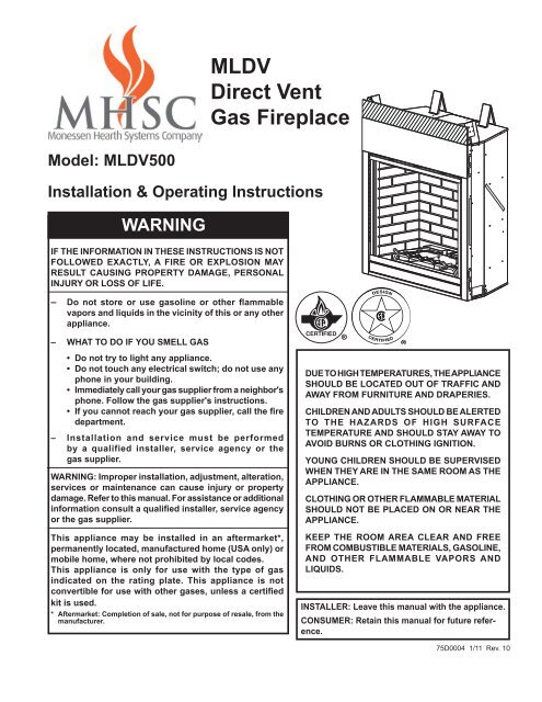
Model: <strong>MLDV</strong>500<br />
<strong>MLDV</strong><br />
<strong>Direct</strong> <strong>Vent</strong><br />
<strong>Gas</strong> <strong>Fireplace</strong><br />
Installation & Operating Instructions<br />
WARNING<br />
IF THE INFORMATION IN THESE INSTRUCTIONS IS NOT<br />
FOLLOWED ExACTLY, A FIRE OR ExPLOSION MAY<br />
RESULT CAUSING PROPERTY DAMAGE, PERSONAL<br />
INjURY OR LOSS OF LIFE.<br />
– Do not store or use gasoline or other flammable<br />
vapors and liquids in the vicinity of this or any other<br />
appliance.<br />
– WHAT TO DO IF YOU SMELL GAS<br />
• Do not try to light any appliance.<br />
• Do not touch any electrical switch; do not use any<br />
phone in your building.<br />
• Immediately call your gas supplier from a neighbor's<br />
phone. Follow the gas supplier's instructions.<br />
• If you cannot reach your gas supplier, call the fire<br />
department.<br />
– Installation and service must be performed<br />
by a qualified installer, service agency or the<br />
gas supplier.<br />
WARNING: Improper installation, adjustment, alteration,<br />
services or maintenance can cause injury or property<br />
damage. Refer to this manual. For assistance or additional<br />
information consult a qualified installer, service agency<br />
or the gas supplier.<br />
This appliance may be installed in an aftermarket*,<br />
permanently located, manufactured home (USA only) or<br />
mobile home, where not prohibited by local codes.<br />
This appliance is only for use with the type of gas<br />
indicated on the rating plate. This appliance is not<br />
convertible for use with other gases, unless a certified<br />
kit is used.<br />
* Aftermarket: Completion of sale, not for purpose of resale, from the<br />
manufacturer.<br />
75d0004<br />
<strong>MLDV</strong> cover<br />
DUE TO HIGH TEMPERATURES, THE APPLIANCE<br />
SHOULD BE LOCATED OUT OF TRAFFIC AND<br />
AWAY FROM FURNITURE AND DRAPERIES.<br />
CHILDREN AND ADULTS SHOULD BE ALERTED<br />
TO THE HAZARDS OF HIGH SURFACE<br />
TEMPERATURE AND SHOULD STAY AWAY TO<br />
AVOID BURNS OR CLOTHING IGNITION.<br />
YOUNG CHILDREN SHOULD BE SUPERVISED<br />
WHEN THEY ARE IN THE SAME ROOM AS THE<br />
APPLIANCE.<br />
CLOTHING OR OTHER FLAMMABLE MATERIAL<br />
SHOULD NOT BE PLACED ON OR NEAR THE<br />
APPLIANCE.<br />
KEEP THE ROOM AREA CLEAR AND FREE<br />
FROM COMBUSTIBLE MATERIALS, GASOLINE,<br />
AND OTHER FLAMMABLE VAPORS AND<br />
LIqUIDS.<br />
INSTALLER: Leave this manual with the appliance.<br />
CONSUMER: Retain this manual for future reference.<br />
75D0004 1/11 Rev. 10
<strong>MLDV</strong> Series <strong>Gas</strong> <strong>Fireplace</strong> CONTENTS<br />
Thank you and congratulations on your purchase of an<br />
<strong>MHSC</strong> <strong>Fireplace</strong>.<br />
PLEASE READ THE INSTALLATION AND OPERATION INSTRUCTIONS BEFORE USING THE APPLIANCE!<br />
IMPORTANT: Read all instructions and warnings carefully before starting installation.<br />
Failure to follow these instructions may result in a possible fire hazard and will void the warranty.<br />
Important Safety Information ..................................... 3<br />
Code Approval ............................................................. 4<br />
Product Specifications................................................ 5<br />
High Elevations ....................................................... 5<br />
<strong>Gas</strong> Pressures ........................................................ 5<br />
<strong>Gas</strong> Specifications & Orifice Size ........................... 5<br />
<strong>Fireplace</strong> & Framing Dimensions .............................. 6<br />
Pre-Installation Information ........................................ 7<br />
Before You Start ...................................................... 7<br />
Items Required for Installation ................................ 7<br />
Firebox Framing ...................................................... 7<br />
<strong>Fireplace</strong> Location ................................................... 7<br />
Clearances ................................................................... 8<br />
Secure <strong>Fireplace</strong> to Floor or Framing........................ 9<br />
Finishing Material .................................................... 9<br />
<strong>Vent</strong>ing Installation .................................................... 10<br />
Installation Precautions ......................................... 10<br />
Optional Top <strong>Vent</strong> Application ............................... 11<br />
<strong>Vent</strong> Pipe Clearances ........................................... 1<br />
Installation Planning .............................................. 13<br />
Horizontal & Vertical Terminations ........................ 13<br />
Termination Location ............................................. 14<br />
Termination Clearances ........................................ 15<br />
How to Use the <strong>Vent</strong> Graph .................................. 15<br />
Rear Wall <strong>Vent</strong> Installation .................................... 16<br />
Horizontal w/Vertical Rise Termination Config. ..... 18<br />
Below Grade Installations ..................................... 1<br />
Vertical Through-the-Roof Applications .................<br />
Installation for Vertical Termination ....................... 4<br />
Flat Ceiling Installation .......................................... 4<br />
Flex <strong>Vent</strong> Installation ............................................. 6<br />
<strong>Fireplace</strong> Installation ................................................. 29<br />
Check <strong>Gas</strong> Type.................................................... 9<br />
<strong>Gas</strong> Line Installation ............................................. 30<br />
Check <strong>Gas</strong> Pressure - Millivolt ................................ 31<br />
Electrical Installation - Millivolt ................................ 31<br />
Remote Wall Mounted Switch ............................... 3<br />
Optional Fan/Blower - BLOTBLDV) ...................... 3<br />
Operating Instructions - Millivolt ............................. 35<br />
For Your Safety ..................................................... 35<br />
Lighting Pilot for the First Time ............................. 35<br />
Lighting Pilot ......................................................... 36<br />
Lighting Burner ...................................................... 37<br />
Checking <strong>Gas</strong> Pressure - SCS ................................. 38<br />
Electrical Wiring - SCS ............................................. 38<br />
Junction Box Wiring .............................................. 39<br />
Command Center Wall Installation ........................ 39<br />
Wall Switch Installation ......................................... 39<br />
Signature Command Wiring Diagram ................... 40<br />
Optional Fan/Blower System - SCS ......................... 41<br />
BLOTSDVSC ........................................................ 41<br />
BLOTSDV ............................................................. 4<br />
Operating Instructions - SCS ................................... 43<br />
For Your Safety ..................................................... 43<br />
Operating Instructions ........................................... 44<br />
To Turn Off <strong>Gas</strong> To Appliance ............................... 44<br />
Signature Command System Operation.................. 45<br />
Final Installation ........................................................ 48<br />
Glass Frame Removal .......................................... 48<br />
Brick Installation .................................................... 48<br />
Eyebrow/Canopy Installation ................................ 48<br />
Rockwool Placement ............................................ 49<br />
Log Placement ...................................................... 49<br />
Cleaning and Maintenance ....................................... 52<br />
Burner, Pilot and Control Compartment ................ 5<br />
Pilot Flame ............................................................ 5<br />
Burner Flame ........................................................ 5<br />
<strong>Vent</strong> System .......................................................... 53<br />
Glass Door ............................................................ 53<br />
Logs ...................................................................... 53<br />
Rock Wool ............................................................ 53<br />
Troubleshooting ........................................................ 54<br />
Standing Pilot Ignition ........................................... 54<br />
Signature Command System ................................ 56<br />
Replacement Parts .................................................... 57<br />
Firebox Components ............................................. 57<br />
Logs ...................................................................... 58<br />
Standing Pilot Millivolt Control ............................. 59<br />
Signature Command System ................................ 61<br />
<strong>Vent</strong>ing Components ............................................. 63<br />
Massachusetts Residents Only................................ 70<br />
Warranty ..................................................................... 71<br />
Efficiencies................................................................. 72<br />
75D0004
IMPORTANT SAFETY INFORMATION<br />
INSTALLER<br />
Please leave these instructions with the appliance.<br />
WARNING<br />
OWNER<br />
<strong>MLDV</strong> Series <strong>Gas</strong> <strong>Fireplace</strong><br />
Please retain these instructions for future reference.<br />
• Read this owner’s manual carefully and completely before trying to assemble,<br />
operate, or service this fireplace.<br />
• Any change to this fireplace or its controls can be dangerous.<br />
• Improper installation or use of this fireplace can cause serious injury or<br />
death from fire, burns, explosions, electrical shock and carbon monoxide<br />
poisoning.<br />
This fireplace is a vented product. This fireplace must be 4. Never install the fireplace<br />
properly installed by a qualified service person. The glass<br />
door must be properly seated and sealed. If this unit is not<br />
properly installed by a qualified service person with glass<br />
door properly seated and sealed, combustion leakage<br />
can occur.<br />
CARBON MONOxIDE POISONING: Early signs of carbon<br />
monoxide poisoning are similar to the flu with headaches,<br />
• in a recreational vehicle<br />
• where curtains, furniture, clothing, or other flammable<br />
objects are less than 4 " from the front, top,<br />
or sides of the fireplace<br />
• in high traffic areas<br />
• in windy or drafty areas<br />
dizziness and/or nausea. If you have these signs, the fire- 5. This fireplace reaches high temperatures. Keep chilplace<br />
may not have been installed properly. Get fresh air dren and adults away from hot surfaces to avoid burns<br />
at once! Have the fireplace inspected and serviced by a or clothing ignition. <strong>Fireplace</strong> will remain hot for a time<br />
qualified service person. Some people are more affected after shutdown. Allow surfaces to cool before touch-<br />
by carbon monoxide than others. These include pregnant ing.<br />
women, people with heart or lung disease or anemia, 6. Young children should be carefully supervised when<br />
those under the influence of alcohol, and those at high they are in the same room as the appliance. Toddlers,<br />
altitudes.<br />
young children and others may be susceptible to<br />
Propane/LP gas and natural gas are both odorless. An<br />
odor-making agent is added to each of these gases. The<br />
odor helps you detect a gas leak. However, the odor added<br />
to these gases can fade. <strong>Gas</strong> may be present even though<br />
no odor exists.<br />
Make certain you read and understand all warnings. Keep<br />
this manual for reference. It is your guide to safe and proper<br />
operation of this fireplace.<br />
1. This appliance is only for use with the type of gas<br />
indicated on the rating plate. This appliance is not<br />
convertible for use with other gases unless a certified<br />
kit is used.<br />
. For propane/LP fireplace, do not place propane/LP<br />
supply tank(s) inside any structure. Locate propane/<br />
LP supply tank(s) outdoors. To prevent performance<br />
problems, do not use propane/LP fuel tank of less than<br />
100 lbs. capacity.<br />
3. If you smell gas<br />
• shut off gas supply.<br />
• do not try to light any appliance.<br />
accidental contact burns. A physical barrier is recommended<br />
if there are at risk individuals in the house. To<br />
restrict access to a fireplace or stove, install an adjustable<br />
safety gate to keep toddlers, young children and<br />
other at risk individuals out of the room and away from<br />
hot surfaces.<br />
7. Do not modify fireplace under any circumstances. Any<br />
parts removed for servicing must be replaced prior to<br />
operating fireplace.<br />
8. Turn fireplace off and let cool before servicing, installing,<br />
or repairing. Only a qualified service person should<br />
install, service, or repair the fireplace. Have burner<br />
system inspected annually by a qualified service<br />
person.<br />
9. You must keep control compartments, burners, and<br />
circulating air passages clean. More frequent cleaning<br />
may be needed due to excessive lint and dust.<br />
Turn off the gas valve and pilot light before cleaning<br />
fireplace.<br />
10. Have venting system inspected annually by a qualified<br />
service person. If needed, have venting system<br />
• do not touch any electrical switch; do not use any cleaned or repaired. See Cleaning and Maintenance,<br />
phone in your building .<br />
Page 5 .<br />
• immediately call your gas supplier from a neighbor’s 11. Keep the area around your fireplace clear of combus-<br />
phone. Follow the gas supplier’s instructions.<br />
tible materials, gasoline, and other flammable vapor<br />
and liquids. Do not run fireplace where these are used<br />
or stored. Do not place items such as clothing or decorations<br />
on or around fireplace.<br />
75D0004 3
<strong>MLDV</strong> Series <strong>Gas</strong> <strong>Fireplace</strong> IMPORTANT SAFETY INFORMATION<br />
1 . Do not use this fireplace to cook food or burn paper or<br />
other objects.<br />
13. Never place anything on top of fireplace.<br />
14. Do not use any solid fuels (wood, coal, paper, cardboard,<br />
etc.) in this fireplace. Use only the gas type<br />
indicated on rating plate.<br />
15. This appliance, when installed, must be electrically<br />
grounded in accordance with local codes or in the<br />
absence of local codes, with the National Electrical<br />
Code, ANSI/NFPA 70, or the Canadian Electrical Code,<br />
CSA C22.1.<br />
16. Do not obstruct the flow of combustion and ventilation<br />
air in any way. Provide adequate clearances around<br />
air openings into the combustion chamber along with<br />
adequate accessibility clearance for servicing and<br />
proper operation.<br />
17. When the appliance is installed directly on carpeting,<br />
tile or other combustible material other than wood<br />
flooring, you must set appliance on a metal or wood<br />
panel or hearth pad extending the full width and depth<br />
of the appliance.<br />
18. Do not use fireplace if any part has been exposed to<br />
or has been under water. Immediately call a qualified<br />
service technician to inspect the appliance and replace<br />
any part of the control system and any gas control<br />
which as been submerged in water.<br />
19. Do not operate fireplace if any log is broken.<br />
0. Do not use a blower insert, heat exchanger insert, or<br />
any other accessory not approved for use with this<br />
fireplace.<br />
1. Do not operate the fireplace with glass door removed,<br />
cracked, or broken.<br />
CODE APPROVAL<br />
<strong>Direct</strong> <strong>Vent</strong> type appliances draw all combustion air from<br />
outside of the dwelling through the vent pipe.<br />
These appliances have been tested by CSA and found to<br />
comply with the established standards for DIRECT VENT<br />
GAS FIREPLACE HEATERS in the USA and Canada as<br />
follows:<br />
4<br />
LISTED VENTED GAS FIREPLACE HEATER<br />
TESTED TO:<br />
ANSI Z 1.88- 009 / CSA .33- 009 STANDARDS<br />
A manufactured home (USA only) or mobile home OEM<br />
installation must conform with the Manufactured Home<br />
Construction and Safety Standard, Title 24 CFR, Part<br />
3280, or when such a standard is not applicable, the<br />
Standard for Manufactured Home Installations, ANSI/<br />
NCSBCS A225.1, or Standard for <strong>Gas</strong> Equipped Recreational<br />
Vehicles and Mobile Housing, CSA Z240.4.<br />
IMPORTANT:<br />
PLEASE READ THE FOLLOWING<br />
CAREFULLY<br />
It is normal for fireplaces fabricated of steel to give off<br />
some expansion and/or contraction noises during the<br />
start up or cool down cycle. Similar noises are found<br />
with your furnace heat exchanger or car engine.<br />
IMPORTANT:<br />
PLEASE READ THE FOLLOWING<br />
CAREFULLY<br />
It is not unusual for gas fireplaces to give off some<br />
odor the first time it is burned. This is due to the<br />
manufacturing process.<br />
Please ensure that your room is well ventilated<br />
during burn off — open all windows.<br />
It is recommended that you burn your fireplace for at<br />
least ten (10) hours the first time you use it. Place the<br />
fan switch in the “OFF” position during this time.<br />
WARNING<br />
Never connect unit to private (nonutility)<br />
gas wells. This gas is commonly<br />
known as wellhead gas.<br />
!<br />
WARNING<br />
HOT GLASS WILL<br />
Nous recommandons<br />
CAUSE BURNS.<br />
que nos<br />
appareils de chauffage au gaz<br />
soient installés DO NOT et TOUCH entretenus GLASS par<br />
des professionnels UNTIL COOLED. qui ont été<br />
accrédités NEVER aux ALLOW È.U. par CHILDREN le National<br />
<strong>Fireplace</strong> Institute TO TOUCH ® (NFI) GLASS.<br />
comme<br />
étant des spécialistes du NFI en<br />
matièred’appareils de chauffage 75D0004<br />
au gaz.
PRODUCT FEATURES<br />
PRODUCT SPECIFICATIONS<br />
• This appliance has been certified for use with<br />
either natural or propane gas. See appropriate<br />
data plates.<br />
• This appliance is not for use with solid fuels.<br />
• The appliance is approved for bedroom or bedsitting<br />
room installations.<br />
• The appliance must be installed in accordance<br />
with local codes if any. If none exist use the current<br />
installation code. ANSI Z 3.1/NFPA 54 in<br />
the USA, CSA B149 in Canada.<br />
• This appliance is mobile home appr-oved.<br />
• The appliance must be properly connected to a<br />
venting system.<br />
• The appliance is not approved for closet or<br />
recessed installations.<br />
HIGH ELEVATIONS<br />
Ignitor<br />
On/Off/RS<br />
Switch<br />
Input ratings are shown in BTU per hour and are certified<br />
without deration for elevations up to 4,500 feet<br />
(1,370 m) above sea level.<br />
For elevations above 4,500 feet (1,370 m) in USA,<br />
installation must be in accordance with the current<br />
ANSI Z 3.1/NFPA 54 and/or local codes having<br />
jurisdiction.<br />
In Canada, please consult provincial and/or local<br />
authorities having jurisdiction for installation at elevations<br />
above 4,500 feet (1,370 m).<br />
GAS PRESSURES<br />
Natural Propane (LP)<br />
Inlet Minimum 4.5” w.c. 11.0” w.c.<br />
Inlet Maximum 10.5” w.c. 13.0” w.c.<br />
Manifold Pressure 3.5” w.c. 10.0” w.c.<br />
Hi/Lo Knob<br />
Off/Pilot/On Knob<br />
Figure 1 -<br />
<strong>MLDV</strong> Series <strong>Fireplace</strong><br />
(Millivolt Control shown)<br />
FP1984<br />
<strong>MLDV</strong> Series <strong>Gas</strong> <strong>Fireplace</strong><br />
Insulation Board<br />
<strong>MLDV</strong> components<br />
GAS SPECIFICATIONS & ORIFICE SIZE<br />
5/8" Nailing<br />
Flange<br />
1/ " Nailing<br />
Flange<br />
75D0004 5<br />
FP1984<br />
Max.Input Min. Input Orifice<br />
Model Fuel BTU/h BTU/h Size<br />
<strong>MLDV</strong>500NV Nat. 34,000 ,000 #33<br />
<strong>MLDV</strong>500PV LP 34,000 7,000 1.8 mm<br />
<strong>MLDV</strong>500NSC Nat. 34,000 ,000 #33<br />
<strong>MLDV</strong>500PSC LP 34,000 7,000 1.8 mm
<strong>MLDV</strong> Series <strong>Gas</strong> <strong>Fireplace</strong> FIREPLACE and FRAMING DIMENSIONS<br />
6<br />
52���” (1327 mm)<br />
WARNING<br />
NOTE<br />
36���”<br />
(921 mm)<br />
52���” (1327 mm)<br />
72���” (1791 mm)<br />
22���”<br />
(565 mm)<br />
22���”<br />
(565 mm)<br />
Min. Rough<br />
Opening<br />
Height<br />
Min. Rough<br />
Opening<br />
Depth<br />
50���”<br />
(1292 mm)<br />
2���"<br />
(64 mm)<br />
Figure 2 -<br />
<strong>Fireplace</strong> and Framing Dimensions<br />
Do not fill spaces around firebox with<br />
insulation or other materials. This<br />
could cause a fire.<br />
COLD CLIMATE INSULATION<br />
27����”<br />
(694 mm)<br />
33” (838 mm)<br />
36” (914 mm)<br />
41” (1041 mm)<br />
750005<br />
DVML <strong>MLDV</strong> dims<br />
If you live in a cold climate, seal all cracks<br />
around your appliance, and wherever cold air<br />
could enter the room, with noncombustible<br />
material. It is especially important to insulate<br />
the outside chase cavity between the studs<br />
and under the floor on which the appliance<br />
rests, if the floor is above ground level.<br />
30���” (784 mm)<br />
20���”<br />
(524 mm)<br />
Min. Rough Opening Width<br />
(42���” 91080 mm)<br />
3���”<br />
(79 mm)<br />
6”<br />
(152 mm)<br />
9�����”<br />
(246 mm)<br />
34”<br />
(864 mm)<br />
1”<br />
(25 mm)<br />
1/2” or 5/8”<br />
50���”<br />
(1289 mm)<br />
1���”<br />
(38 mm)<br />
7���”<br />
(187 mm)<br />
14���”<br />
(368 mm)<br />
2”<br />
(51 mm)<br />
38���”<br />
(984 mm)<br />
44���”<br />
(1133 mm)<br />
46���”<br />
(1184 mm)<br />
75D0004
INSTALLATION INFORMATION<br />
BEFORE YOU START<br />
Read this homeowner manual thoroughly and follow all<br />
instructions carefully. Inspect all contents for shipping<br />
damage and immediately inform your dealer if any damage<br />
is found. Do not install any unit with damaged, incomplete,<br />
or substitute parts. Check your packing list to verify that<br />
all listed parts have been received. You should have the<br />
following:<br />
• <strong>Fireplace</strong> (Firebox and Burner System)<br />
• Log Set<br />
• Rock Wool<br />
ITEMS REqUIRED FOR INSTALLATION<br />
Tools and Building Materials<br />
• Phillips Screwdriver • Framing Materials<br />
• Hammer • Wall Finishing Materials<br />
• Saw and/or saber saw • Level<br />
• Measuring Tape • Pliers<br />
• Electric Drill and Bits • Square<br />
• Pipe Wrench • Tee Joint<br />
• Caulking Material (noncombustible)<br />
• <strong>Fireplace</strong> Surround Material (noncombustible)<br />
• Piping Complying with Local Codes<br />
• Pipe Sealant Approved for use with Propane/LPG<br />
(Resistant to sulfur compounds)<br />
FIREBOx FRAMING<br />
Firebox framing can be built before or after the appliance<br />
is set in place. Construct firebox framing following Figure 2<br />
for firebox and framing dimensions. The framing headers<br />
may rest on the top of the firebox standoffs. Do not bring<br />
headers below top of standoffs. NOTE: When planning your<br />
framing and installation, keep in mind that your gas line will<br />
come in on the right side of the box (as you are facing it)<br />
and your electricity will come in on the left side.<br />
The firebox may be installed directly on a combustible floor<br />
or raised on a platform of an appropriate height. When<br />
the firebox is installed directly on carpeting, tile, or other<br />
combustible material, other than wood flooring, the firebox<br />
shall be installed on a metal or wood panel extending the<br />
full width and depth of the enclosure.<br />
<strong>MLDV</strong> Series <strong>Gas</strong> <strong>Fireplace</strong><br />
FIREPLACE LOCATION<br />
Plan for the installation of your appliance. This includes<br />
determining where the unit is to be installed, the vent configuration<br />
to be used, framing and finishing details, and<br />
whether any optional accessories (i.e. blower, wall switch,<br />
or remote control) are desired. Consult your local building<br />
code agency to ensure compliance with local codes, including<br />
permits and inspections.<br />
The following factors should be taken into consideration:<br />
• Clearance to side-wall, ceiling, woodwork, and windows.<br />
Minimum clearances to combustibles must be maintained.<br />
• This fireplace may be installed along a wall, across a<br />
corner, or use an exterior chase. Refer to Figure 3 for<br />
suggested locations.<br />
• Location should be out of high traffic areas and away<br />
from furniture and draperies due to heat from appliance.<br />
• Never obstruct the front opening of the fireplace.<br />
• Do not install in the vicinity where gasoline or other<br />
flammable liquids may be stored.<br />
• <strong>Vent</strong> pipe routing. See <strong>Vent</strong>ing section found in this<br />
manual for allowable venting configurations.<br />
• These units can be installed in a bedroom. See National<br />
Fuel <strong>Gas</strong> Code ANSI Z 33.1/NFPA 54 — (current<br />
edition), the Uniform Mechanical Code — (current edition),<br />
and Local Building Codes for specific installation<br />
requirements.<br />
• These units can be installed in a bathroom.<br />
** Island (C) and room divider (D) installation is possible as long as the<br />
horizontal portion of vent system (X) does not exceed 0'. See Install<br />
Horizontal Termination Configuration on Pages 18 and 19.<br />
* When you install your fireplace in (D) room divider or (E) flat on wall<br />
corner positions (Y), a minimum of 6" clearance must be maintained<br />
from perpendicular wall and front of fireplace.<br />
75D0004 7<br />
Y<br />
Y<br />
E A<br />
D<br />
F<br />
Figure 3 -<br />
Locate <strong>Gas</strong> <strong>Fireplace</strong><br />
C<br />
X<br />
B<br />
A Flat on Wall<br />
B Cross Corner<br />
C Island**<br />
D Room Divider*<br />
E Flat on Wall Corner*<br />
F Chase Installation<br />
Y 6" Minimum
<strong>MLDV</strong> Series <strong>Gas</strong> <strong>Fireplace</strong><br />
CLEARANCES TO COMBUSTIBLES<br />
WARNING<br />
8<br />
Follow these instructions carefully to ensure safe installation. Failure<br />
to follow instructions exactly can create a fire hazard.<br />
The appliance cannot be installed on a carpet, tile or other combustible<br />
material other than wood flooring. If installed on carpet or vinyl flooring,<br />
the appliance shall be installed on a metal, wood or noncombustible<br />
material panel extending full width and depth of the appliance.<br />
71” Minimum<br />
Ceiling<br />
12” Max.<br />
Depth<br />
6” Min.<br />
to Opening<br />
Side Wall<br />
Figure 4 -<br />
Side Wall and Ceiling Clearances<br />
Combustible<br />
Mantel<br />
14” Min.<br />
From Opening<br />
NOTE: When eyebrow canopy is used, minimum clearance to<br />
combustibles is Z\v" maximum out from fireplace front at 7Z\x"<br />
minimum from opening. Figure 5a. When eyebrow is not used,<br />
clearances to combustibles is 8" maximum out from fireplace<br />
FP1987<br />
front at 10" minimum clearances from opening or 1 " maximum out from<br />
fireplace front at 14" minimum from opening. Figure 5<br />
14”<br />
Min.<br />
<strong>Fireplace</strong><br />
Opening<br />
Top View<br />
1"<br />
2���"<br />
3"<br />
5"<br />
6"<br />
Figure 5 -<br />
Mantel clearances.<br />
FP1949<br />
12” Max.<br />
10”<br />
Min.<br />
mantel clearances<br />
8” Max.<br />
7���”<br />
Min.<br />
1���"<br />
3���"<br />
4���"<br />
CLEARANCES<br />
Wall<br />
Combustible<br />
Material Area<br />
45°<br />
1���”<br />
Max. 2���” Max.<br />
Figure 5a -<br />
Mantel Clearance with Eyebrow Canopy<br />
FP2916<br />
Mantel Clearance<br />
Eyebrow<br />
Canopy<br />
Combustible<br />
Breastplate<br />
3/4"<br />
Marble<br />
75D0004
SECURE FIREPLACE TO FLOOR OR FRAMING<br />
The fireplace must be secured to the floor and/or to framing studs as shown in Figure 6. Use<br />
two ( ) wood screws or masonry/ concrete screws to secure fireplace to the floor. Use four (4)<br />
screws to attach fireplace to framing. The side nailing flanges are 1/ " or 5/8" to accommodate<br />
different wall thickness.<br />
Screws<br />
Framing<br />
Nailing Flange<br />
Figure 6 -<br />
Secure <strong>Fireplace</strong> to Floor and<br />
Framing Studs<br />
FINISHING MATERIAL<br />
Insulation Board<br />
DO NOT REMOVE<br />
NOTE: Any remote wiring (i.e. remote control, wall switch, and optional fan) must be done<br />
prior to final finishing to avoid costly reconstruction. FP1989<br />
install fireplace<br />
<strong>MLDV</strong> Series <strong>Gas</strong> <strong>Fireplace</strong><br />
75D0004 9<br />
NOTE<br />
DO NOT REMOVE INSULATION<br />
BOARD<br />
FP1989<br />
Only noncombustible materials (i.e. brick, tile, slate, steel, or other materials with a UL fire rating of<br />
Zero) may be used to cover the black painted face of the appliance. It is permissible to bring combustible<br />
wall board to the top and side edges of the black painted face. A 300°F minimum adhesive<br />
may be used to attach facing materials to the black surface. If joints between the finished wall and<br />
the fireplace surround are sealed, a 300°F minimum sealant material (General Electric RTV103 or<br />
equivalent) must be used.
<strong>MLDV</strong> Series <strong>Gas</strong> <strong>Fireplace</strong><br />
VENTING INSTALLATION<br />
WARNING<br />
INSTALLATION PRECAUTIONS<br />
Consult local building codes before beginning the installation. The installer must make sure to select<br />
the proper vent system for installation. Before installing vent kit, the installer must read this fireplace<br />
manual and vent kit instructions.<br />
Only a qualified installer/service person should install venting system. The installer must follow<br />
these safety rules:<br />
10<br />
Read all instructions completely and<br />
thoroughly before attempting installation.<br />
Failure to do so could result in serious injury,<br />
property damage or loss of life. Operation<br />
of improperly installed and maintained<br />
venting system could result in serious injury,<br />
property damage or loss of life.<br />
NOTICE<br />
• Wear gloves and safety glasses for protection.<br />
• Use extreme caution when using ladders or when on rooftops.<br />
• Be aware of electrical wiring locations in walls and ceilings.<br />
The following actions will void the warranty on your venting system:<br />
• Installation of any damaged venting component.<br />
• Unauthorized modification of the venting system.<br />
• Installation of any component part not manufactured or approved by <strong>MHSC</strong>.<br />
• Installation other than permitted by these instructions.<br />
VENTING INSTALLATION<br />
Failure to follow these instructions<br />
will void the warranty.<br />
75D0004
VENTING INSTALLATION<br />
OPTIONAL TOP VENT APPLICATION<br />
The appliance is shipped as a rear vent unit. If the installation<br />
layout requires the unit to be a top vent configuration,<br />
the appliance can be converted by following the steps<br />
below.<br />
When removing and refitting the plates and adapter, be<br />
sure the associated gaskets are undamaged and refitted<br />
as required.<br />
1. Remove the eight (8) screws securing the flue pipe<br />
adapter to the fireplace body. Figure 7<br />
. Set the flue pipe adapter aside, complete with the<br />
gasket. Do not damage the gaskets as the adapter and<br />
gasket must be refitted.<br />
Flue Pipe<br />
Cover<br />
Screws<br />
Flue Pipe<br />
FP1991<br />
Adapter<br />
Figure 7 -<br />
Remove 16 screws from Flue Pipe Adapter and<br />
Flue Pipe Cover<br />
3. Remove the eight (8) screws securing the flue pipe cover<br />
to the top of the intake box and remove the cover and<br />
gasket. Figure<br />
FP1991<br />
7<br />
4. Remove six remove (6) screws securing the flue pipe to the<br />
back of the intake box and remove the pipe and gasket.<br />
Figure 8<br />
5. Replace the flue pipe to top of firebox. Ensure the gasket<br />
is in place and undamaged. Secure with six (6) screws.<br />
Figure 9<br />
6. Place the flue pipe cover and gasket removed in Step<br />
3 over the flue opening in bottom of the intake box.<br />
7. Refit the flue pipe adapter and gasket to the top of fireplace.<br />
Secure the adapter with six (6) screws removed<br />
in Step 1.<br />
Flue Pipe<br />
Figure 8 -<br />
Remove Flue Pipe<br />
FP1992<br />
remove flue pipe<br />
<strong>MLDV</strong> Series <strong>Gas</strong> <strong>Fireplace</strong><br />
Flue Cover<br />
75D0004 11<br />
WARNING<br />
After conversion to top vent configuration,<br />
the 5" (127 mm) flue pipe should be<br />
concentric with the 8" (203 mm) outer collar<br />
within 1/4".<br />
Screws<br />
FP1993<br />
replace flue pipe<br />
Flue Pipe<br />
FP199<br />
Screws<br />
FP1993<br />
Figure 9 -<br />
Attach Flue Pipe to Top <strong>Vent</strong> Configuration
<strong>MLDV</strong> Series <strong>Gas</strong> <strong>Fireplace</strong><br />
WARNING<br />
1<br />
Horizontal sections of this vent system<br />
require a minimum of 3” clearances to<br />
combustibles at the top of the flue and 1”<br />
clearance at the sides and bottom until<br />
the flue penetrates the outside wall. A<br />
minimum 1” clearance all around the flue<br />
is acceptable at this point of penetration. If<br />
vertical rise is 7Z\x” feet or higher when top<br />
venting, the clearance to combustibles is<br />
1” on all sides of the horizontal run.<br />
Vertical sections of this vent system require<br />
a minimum of 1” clearance to combustibles<br />
on all sides of the pipe.<br />
*3”<br />
**1”<br />
**1”<br />
WARNING<br />
Figure 10 -<br />
Combustible Clearances for <strong>Vent</strong> Pipe<br />
fP1990<br />
vent pipe clearances<br />
VENTING INSTALLATION<br />
This fireplace must be vented to the<br />
outside. The venting system must NEVER<br />
be attached to a chimney serving a separate<br />
solid fuel burning appliance. Each gas<br />
appliance must use a separate vent system.<br />
Do not use common vent systems.<br />
* A minimum of 3" clearance to the top is required<br />
along horizontal length until flue pipe penetrates<br />
outside wall.<br />
** A minimum 1" clearance to combustibles permitted<br />
all around flue at outside wall<br />
*3”<br />
FP1990<br />
**1”<br />
**1”<br />
75D0004
VENTING INSTALLATION<br />
WARNING<br />
INSTALLATION PLANNING<br />
There are two basic types of direct-vent installation:<br />
• Horizontal Termination<br />
• Vertical Termination<br />
It is important to select the proper length of vent pipe for<br />
the type of termination you choose. It is also important to<br />
note the wall thickness.<br />
FOR HORIZONTAL TERMINATION<br />
Select the amount of vertical rise desired. All horizontal run<br />
of venting must have 1/4" rise for every 1 " of run towards<br />
the termination below 7 1 / feet of vertical rise. With 7 1 / feet<br />
or more vertical rise off top of fireplace, the horizontal run<br />
may run level. NEVER run vent piping downward.<br />
You may use up to three 90° elbows in this vent configuration.<br />
Refer to Horizontal Termination Configurations on<br />
Pages 17 and 18.<br />
FOR VERTICAL TERMINATION<br />
Measure the distance from the fireplace floor to the ceiling.<br />
Add the ceiling thickness, the vertical rise in an attic<br />
or second story, and allow for sufficient vent height above<br />
the roof line.<br />
NOTE: You may use two 45° elbows in place of a 90° elbow.<br />
You must follow rise to run ratios when using 45° elbows.<br />
The appliance is approved for use with three 90° elbows<br />
maximum or a combination of 90° and 45° elbows up to a<br />
maximum of 70°.<br />
For two-story applications, firestops are required at each<br />
floor level. If an offset is needed in the attic, additional pipe<br />
and elbows will be required.<br />
You may use a chase with a vent termination with exposed<br />
pipe on the exterior of the house. Refer to Installing <strong>Vent</strong><br />
System in a Chase below. If pipe is enclosed in chase, it<br />
is not exposed.<br />
It is very important that the venting system maintain its balance<br />
between the combustion air intake and the flue gas<br />
exhaust. Certain limitations apply to vent configurations<br />
and must be strictly followed.<br />
INSTALLING A VENT SYSTEM IN AN<br />
OUTSIDE CHASE<br />
A chase is a vertical boxlike structure built to enclose<br />
venting that runs along the outside of a building. A chase<br />
is required for such venting.<br />
<strong>MLDV</strong> Series <strong>Gas</strong> <strong>Fireplace</strong><br />
Read all instructions completely and thoroughly before attempting installation. Failure<br />
to do so could result in serious injury, property damage or loss of life. Operation of<br />
improperly installed and maintained venting system could result in serious injury,<br />
property damage or loss of life.<br />
75D0004 13<br />
WARNING<br />
WARNING<br />
NOTICE<br />
WARNING<br />
Never run the vent pipe down. This may<br />
cause excessive temperatures which could<br />
cause a fire.<br />
Treatment of firestops and construction of<br />
the chase may vary from building type to<br />
building type. These instructions are not<br />
substitutes for the requirements of local<br />
building codes. You must follow all local<br />
building codes.<br />
When installing in a chase, you should<br />
insulate the chase as you would the outside<br />
walls of your home. This is especially<br />
important in cold climates. Insulation should<br />
be considered a combustible material.<br />
Maintain proper clearances to all combustible<br />
materials.<br />
Always maintain minimum clearances<br />
around vent systems. The minimum<br />
clearance to combustibles for horizontal<br />
vent pipe are 3” at the top and 1” at the<br />
sides and bottom of the vent system until<br />
the pipe penetrates the nearest vertical<br />
wall (1” required). A 1” minimum clearance<br />
all around the pipe must be maintained at<br />
outside wall and on vertical runs. Do not<br />
pack the open air spaces with insulation<br />
or other materials. This could cause high<br />
temperatures and may present a fire<br />
hazard.<br />
*Unless the vertical run is 7Z\x feet or higher<br />
(top vent units only), the clearances for the<br />
horizontal run is 1” at the top.
<strong>MLDV</strong> Series <strong>Gas</strong> <strong>Fireplace</strong> VENTING INSTALLATION<br />
14<br />
GENERAL VENTING INFORMATION - TERMINATION LOCATION<br />
Figure 11 -<br />
Horizontal <strong>Vent</strong> Termination<br />
Locations<br />
L<br />
D<br />
V<br />
E<br />
B<br />
CFM145a<br />
F<br />
C<br />
V Fixed<br />
Closed<br />
V<br />
Operable<br />
B<br />
V<br />
A<br />
B B<br />
INSIDE<br />
CORNER DETAIL<br />
V<br />
B<br />
Fixed<br />
Operable<br />
Closed<br />
V<br />
A<br />
J<br />
V VENT TERMINATION X AIR SUPPLY INLET AREA WHERE TERMINAL IS NOT PERMITTED<br />
Canadian Installations<br />
A = Clearance above grade, veranda, porch,<br />
CFM145a<br />
1 ” (30 cm) DV Termin Location<br />
1 ” (30 cm)<br />
deck, or balcony<br />
5/01/01 Rev. 12/05/01<br />
sta<br />
B = Clearance to window or door that may be 6” (15 cm) for appliances 6” (15 cm) for appliances<br />
opened < 10,000BTU/h (3kW), 1 ” (30 cm) < 10,000 BTU/h (3kW), 9”<br />
for appliances > 10,000 Btuh (3kW) and ( 3 cm) for appliances > 10,000<br />
< 100,000 BTU/h (30kW), 36” (91 cm) Btuh (3kW) and < 50,000 BTU/h<br />
for appliances > 100,000 BTU/h (30kW) (15kW), 1 ” (30 cm) for<br />
appliances > 50,000 BTU/h(15kW)<br />
C = Clearance to permanently closed window 1 ” (305 mm) recommended to 1 ” (305 mm) recommended to<br />
D = Vertical clearance to ventilated soffit located<br />
prevent window condensation prevent window condensation<br />
above the terminal within a horizontal<br />
distance of ’ (610mm) from the center<br />
line of the terminal<br />
18” (458 mm) 18” (458 mm)<br />
E = Clearance to unventilated soffit 1 ” (305 mm) 1 ” (305 mm)<br />
F = Clearance to outside corner see next page see next page<br />
G = Clearance to inside corner (see next page) see next page see next page<br />
H = Clearance to each inside of center line 3’ (91 cm) within a height of 15’ (5 m) 3’ (91 cm) within a height of 15’<br />
extended above meter/regulator assembly above the meter/regulator assembly (5 m) above the meter/regulator<br />
assy<br />
I = Clearance to service regulator vent outlet 3’ (91 cm) 3’ (91 cm)<br />
J = Clearance to nonmechanical air supply inlet 6” (15 cm) for appliances < 10,000 6” (15 cm) for appliances<br />
to building or the combustion air inlet to any BTU/h (3kW), 1 ” (30 cm) for < 10,000 BTU/h (3kW), 9”<br />
other appliances appliances > 10,000 BTU/h (3kW) and ( 3 cm) for appliances > 10,000<br />
< 100,000 Btuh (30kW), 36” (91 cm) BTU/h (3kW) and < 50,000 BTU/h<br />
for appliances > 100,000 BTU/h (30kW) (15kW), 1 ” (30 cm) for<br />
appliances > 50,000 BTU/h(15kW)<br />
K = Clearance to a mechanical air supply inlet 6’ (1.83 m) 3’ (91 cm) above if within 10'<br />
(3 m) horizontally<br />
L = Clearance above paved sidewalk or paved<br />
driveway located on public property<br />
7’ ( .13 m)† 7’ ( .13 m)†<br />
M = Clearance under veranda, porch, deck or<br />
balcony<br />
1 ” (30 cm) 1 ” (30cm)<br />
1 US Installations2 1 In accordance with the current CSA-B149 Installation Codes<br />
In accordance with the current ANSI Z 3.1/NFPA 54 National Fuel<br />
<strong>Gas</strong> Codes<br />
† A vent shall not terminate directly above a sidewalk or paved<br />
driveway which is located between two single family<br />
dwellings and serves both dwellings<br />
only permitted if veranda, porch, deck or balcony is fully open on a<br />
minimum sides beneath the floor:<br />
G<br />
V<br />
B<br />
X<br />
H<br />
I<br />
M<br />
NOTE: 1. Local codes or regulations may require different<br />
clearances.<br />
. The special venting system used on <strong>Direct</strong> <strong>Vent</strong> <strong>Fireplace</strong>s<br />
are certified as part of the appliance, with clearances<br />
tested and approved by the listing agency.<br />
3. <strong>MHSC</strong> assumes no responsibility for the improper<br />
performance of the appliance when the venting system<br />
does not meet these requirements.<br />
V<br />
K<br />
X<br />
75D0004
VENTING INSTALLATION<br />
Figure 12 -<br />
Allowable<br />
<strong>Vent</strong>ing<br />
Termination Clearances<br />
Termination clearances for buildings with combustible and noncombustible exteriors.<br />
Inside Corner<br />
Outside Corner<br />
Alcove Applications*<br />
HOW TO USE THE VENT GRAPH<br />
G<br />
V<br />
Balcony -<br />
with no side wall<br />
G =<br />
Combustible<br />
6" (152 mm)<br />
Noncombustible<br />
2" (51 mm)<br />
M<br />
M =<br />
Combustible &<br />
Noncombustible<br />
12" (305 mm)<br />
Balcony -<br />
with perpendicular side wall<br />
M = 24" (610 mm)<br />
P = 20” (508 mm)<br />
The <strong>Vent</strong> Graph should be read in conjunction with the following<br />
vent installation instructions to determine the relationship between<br />
the vertical and horizontal dimensions of the vent system.<br />
1. Determine the height of the center of the horizontal vent pipe<br />
exiting through the outer wall. Using this dimension on the<br />
Sidewall <strong>Vent</strong> Graph below, locate the point intersecting with<br />
the slanted graph line.<br />
. From the point of this intersection, draw a vertical line to the<br />
bottom of the graph.<br />
3. Select the indicated dimension, and position the fireplace in<br />
accordance with same.<br />
Example: If the vertical dimension from the floor of the fireplace<br />
is 11' (3.4 m) the horizontal run to the face of the outer wall must<br />
not exceed 14' (4.3 m).<br />
Example: If the vertical dimension from the floor of the unit is<br />
7’ (2.14 m), the horizontal run to the face of the outer wall must<br />
not exceed 7' (2.1 m).<br />
V<br />
V<br />
M<br />
F<br />
Combustible &<br />
Noncombustible<br />
F =<br />
Combustible<br />
6" (152 mm)<br />
Noncombustible<br />
2" (51 mm)<br />
<strong>MLDV</strong> Series <strong>Gas</strong> <strong>Fireplace</strong><br />
Dimensions in<br />
Feet<br />
Sidewall <strong>Vent</strong> Graph showing the relationship between vertical and<br />
2 4 6 8 10 12 14 16 18 20<br />
horizontal dimensions for a <strong>Direct</strong> <strong>Vent</strong> flue system.<br />
Horizontal dimension from the finished outside wall<br />
Figure 13 - to the center of the pipe on the fireplace<br />
Rear Wall <strong>Vent</strong>ing Graph<br />
75D0004 15<br />
V<br />
P<br />
C<br />
O<br />
D<br />
V<br />
E<br />
C<br />
E = Min. 6” (152 mm) for<br />
non-vinyl sidewalls<br />
Min. 12” (305 mm) for<br />
vinyl sidewalls<br />
O = 8’ (2.4 m) Min.<br />
No.<br />
of Caps DMin. CMax.<br />
1 3’ (914 mm) x DActual<br />
6’ (1.8 m) 1 x DActual<br />
3 9’ ( .7 m) /3 x DActual<br />
4 1 ’ (3.7 m) 1/ x DActual<br />
DMin. = # of Termination caps x 3<br />
CMax. = ( / # termination caps) x DActual<br />
584-15<br />
*NOTE: Termination in an alcove space (spaces open only on one side and with an overhang) is permitted with the dimensions specified for vinyl or<br />
non-vinyl siding and soffits. 1. There must be a 3’ (914 mm) minimum between termination caps. . All mechanical air intakes within 10’ (1 m) of a<br />
termination cap must be a minimum of 3’ (914 mm) below the termination cap. 3. All gravity air intakes within 3’ (914 mm) of a termination cap must<br />
be a minimum of 1’ (305 mm) below the termination cap.<br />
40<br />
38<br />
36<br />
34<br />
32<br />
30<br />
28<br />
26<br />
24<br />
22<br />
20<br />
18<br />
16<br />
14<br />
12<br />
10<br />
8<br />
6<br />
4<br />
2<br />
eg: A<br />
FP1952<br />
sidewall vent graph<br />
Vertical Dimension From the Floor of Unit to the<br />
Center of the Horizontal <strong>Vent</strong> Pipe
<strong>MLDV</strong> Series <strong>Gas</strong> <strong>Fireplace</strong><br />
REAR WALL VENT INSTALLATION (5" x 8" VENTING<br />
ONLY)<br />
When installed as a rear vent unit, this appliance may be vented directly to<br />
a termination located on the rear wall behind the appliance. Only an <strong>MHSC</strong><br />
brand termination is allowed for this application.<br />
• The maximum horizontal distance between the rear of the appliance<br />
and the termination is 0" (508 mm). Figure 14<br />
• Only one 45 degree elbow is allowed in these installations.<br />
1. Rigid vent pipes and fittings have special twist-lock connections. Assemble the desired combination<br />
of pipe and elbows to the appliance adapter.<br />
Twist-Lock Procedure: The female ends of the pipes and fittings have three (3) locking lugs (indentations).<br />
These lugs will slide straight into matching slots on the male end of adjacent pipes and<br />
fittings. Push the pipe sections together and twist one section clockwise approximately one-quarter<br />
turn until the sections are fully locked. Figure 15<br />
NOTE: Sealant is not required to assemble fireplace venting. Do not use silicone sealant at<br />
the inner flue exhaust connections.<br />
. Refer to venting and termination instructions<br />
for further instructions.<br />
3. Locate and cut the vent opening in the<br />
wall. For combustible walls first frame in<br />
opening.<br />
Combustible Interior Walls: Cut a 1 1 / "<br />
x 101 / " hole through the interior wall.<br />
Combustible Exterior Walls: Cut a 101 / "<br />
x 101 / " square hole through the exterior<br />
wall frame. Figure 16<br />
Noncombustible Walls: Hole opening<br />
should be 81 Top View Flat Installation<br />
Figure 14 - Rear <strong>Vent</strong> Application,<br />
Maximum DVR584-600 Horizontal Distance<br />
Figure 15 -<br />
Rigid <strong>Vent</strong> Pipe Connections<br />
Rear vent no elbows<br />
FP1953<br />
2/99 djt<br />
rigid pipe<br />
10<br />
/ " ( 16 mm) in diameter.<br />
4. The center of the hole should align with<br />
the center line of the horizontal rigid vent<br />
pipe end. Allow 1/4" minimum rise per foot.<br />
Figure 16<br />
5. Apply a bead of non-hardening mastic<br />
around the outside edge of vent cap. Position<br />
the vent cap in the center of hole on the<br />
exterior wall with the word "UP" on the vent<br />
cap facing up. Insure proper clearance of<br />
1 / "<br />
( 67 mm)<br />
101 / "<br />
( 67 mm)<br />
81 Combustible Wall<br />
/ "<br />
( 16 mm)<br />
Noncombustible<br />
Wall<br />
Figure 16 -<br />
Exterior Wall Framing Dimensions<br />
16<br />
Maximum<br />
0"<br />
FP1954<br />
wall framing<br />
VENTING INSTALLATION<br />
Female Locking<br />
Lugs<br />
NOTE: Horizontal runs of<br />
vent must be supported every<br />
three feet (914 mm). Use wall<br />
straps for this purpose.<br />
Male Slots<br />
FP1954<br />
75D0004
VENTING INSTALLATION<br />
REAR WALL VENT INSTALLATION (continued)<br />
1" to combustibles is maintained. Attach the vent cap with four (4)<br />
wood screws supplied. Figure 17<br />
NOTE: Replace the wood screws with appropriate fasteners for<br />
stucco, brick, concrete or other types of siding.<br />
For vinyl siding, stucco or wood exterior, use vinyl siding standoffs<br />
between vent cap and exterior wall for Simpson or Selkirk Terminations<br />
only. The vinyl siding standoff prevents excessive heat from<br />
melting the vinyl siding material. NOTE: <strong>MHSC</strong> Termination does<br />
not require standoff. Bolt the vent cap to the standoff or wall. Apply<br />
non-hardening mastic around outside edge of the standoff instead<br />
of the vent cap assembly. Use wood screws provided to attach the<br />
standoff. Figure 18<br />
6. Slide the stop over the vent pipe before connecting the horizontal<br />
run to the vent cap. Figure 19<br />
7. Carefully move the fireplace with vent assembly attached toward<br />
the wall and insert the vent pipe into the horizontal termination. The<br />
pipe overlap should be a minimum of 1 /4". Apply silicone to the outer<br />
pipe connection. Fasten all vent connections with screws<br />
provided.<br />
8. Slide the wall thimble against the interior wall surface and<br />
attach with screws. Figure 19<br />
Apply Mastic<br />
to all Four<br />
Sides<br />
NOTICE<br />
FP1956<br />
Nut<br />
Wood Screw<br />
Cut Vinyl Siding Away<br />
to Fit Standoff<br />
Standoff #1 50 or<br />
5DT-VS<br />
(Not required for<br />
<strong>MHSC</strong> termination)<br />
FP1956<br />
All rear<br />
vinyl<br />
vent<br />
siding<br />
through-the-wall applications<br />
must use <strong>MHSC</strong>-designed 5 x 8 square termination.<br />
No other manufacturer's termination is<br />
pemitted in this application.<br />
HOT<br />
Figure 18 -<br />
Install Simpson/Selkirk Vinyl Siding Standoff and<br />
Termination<br />
Bolt<br />
<strong>Vent</strong> Cap<br />
(Horizontal<br />
Termination)<br />
Termination<br />
<strong>MLDV</strong> Series <strong>Gas</strong> <strong>Fireplace</strong><br />
FP1957<br />
vent cap w hor pipe<br />
Inerior Wall<br />
Surface<br />
Firestop<br />
FP1957<br />
Figure 19 -<br />
Screw<br />
Horizontal<br />
<strong>Vent</strong> Pipe<br />
Install Firestop on Horizontal <strong>Vent</strong> Pipe<br />
75D0004 17<br />
WARNING<br />
Apply Mastic to all<br />
Four Sides<br />
HOT<br />
Figure 17 -<br />
Install Horizontal Termination<br />
FP1955<br />
horizontal vent cap<br />
wall. This will cause a fire hazard.<br />
<strong>Vent</strong> Cap<br />
Wood Screw<br />
For more information, follow instructions<br />
provided with terminations.<br />
NOTICE Do not recess vent termination into any
<strong>MLDV</strong> Series <strong>Gas</strong> <strong>Fireplace</strong><br />
HORIZONTAL WITH VERTICAL RISE (THROUGH-THE-WALL)<br />
TERMINATION CONFIGURATIONS<br />
Since it is very important that the venting system maintain its balance between the combustion<br />
air intake and the flue gas exhaust, certain limitations as to vent configurations apply<br />
and must be strictly adhered to.<br />
The <strong>Vent</strong> Graph, showing the relationship between vertical and horizontal side wall venting, will help<br />
to determine the various dimensions allowable. Figure 13<br />
Minimum clearance between vent pipes and combustible materials is 3" on top and 1" from bottom<br />
and sides unless otherwise noted (Exception: Outside wall with firestop: 1" all around pipes are<br />
allowed). If the vertical run is 7 1 / feet or more, off the top of the fireplace, the clearance is 1" on all<br />
sides of the horizontal run.<br />
When vent termination exits through foundations less than 0" below siding outcrop, the vent pipe<br />
must be flush with the siding.<br />
• The maximum number of 90° elbows per side wall installation is three (3). Figure 20<br />
• If a 90° elbow is fitted directly on the top of the fireplace, the maximum horizontal vent run before<br />
the termination or a vertical rise is 36” (914 mm). Figure 21<br />
18<br />
VENTING INSTALLATION<br />
It is best to locate the fireplace in such a way that minimizes the number of offsets and horizontal<br />
vent length.<br />
When installing the appliance as a rear vent unit, the 90° or<br />
The horizontal vent run refers to the total<br />
length of vent pipe from the flue collar 45° transition elbow attached directly to the rear of the unit<br />
of the fireplace (or the top of the Transi- is NOT INCLUDED in the following criteria and calculations<br />
tion Elbow) to the face of the finished and, unless specifically mentioned, should be ignored when<br />
outside wall or the mounting flange of calculating venting layouts.<br />
the termination.<br />
3 x 90°<br />
Elbows<br />
3 x 90°<br />
Elbows<br />
Figure 20 -<br />
Maximum Three (3) 90° Elbows Per Installation<br />
FP1176<br />
max 90 bends<br />
WARNING<br />
FP1176<br />
FP1177<br />
36"<br />
(914 mm)<br />
Max.<br />
Figure 21 -<br />
Maximum Horizontal Run with<br />
No Rise<br />
Max 20"<br />
36"<br />
(914 mm)<br />
Max.<br />
75D0004
VENTING INSTALLATION<br />
HORIZONTAL (THROUGH-THE-WALL) TERMI-<br />
NATION CONFIGURATION (continued)<br />
• If a 90° elbow is used in the horizontal vent run (level height<br />
maintained) the horizontal vent length is reduced by 36".<br />
Figure 23. This does not apply if the 90° elbows are used to<br />
increase or redirect a vertical rise. Figure 22<br />
Example: According to the vent graph (Page 17) the maximum<br />
horizontal vent length in a system with a 7.5' vertical rise is 20’<br />
(6 m) and if a 90° elbow is required in the horizontal vent it must<br />
be reduced to 17' (5.2 m).<br />
In Figures 22 and 23 dimension A plus B must not be greater<br />
than 17' (5. m).<br />
• The maximum number of 45° elbows permitted per side wall<br />
installation is two ( ). These elbows can be installed in either<br />
the vertical or horizontal run.<br />
• For each 45° elbow installed in the horizontal run, the length<br />
of the horizontal run MUST be reduced by 18" (457 mm).<br />
This does not apply if the 45° elbows are installed on the<br />
vertical part of the vent system.<br />
• The maximum number of elbow degrees in a system is 70°.<br />
Figure 24<br />
7'6"<br />
FP1959<br />
A<br />
10'<br />
Horizontal 90° Elbow = 3' Reduction<br />
A + B = 17' Maximum<br />
Figure 23 -<br />
Maximum <strong>Vent</strong> Run with Elbows<br />
B<br />
7'<br />
Figure 22 -<br />
Horizontal Run Reduction<br />
<strong>MLDV</strong> Series <strong>Gas</strong> <strong>Fireplace</strong><br />
Example: Elbow 1 = 90°<br />
FP1958 Elbow = 45°<br />
Horizontal run Elbow reduction 3 = 45°<br />
Elbow 4 = 90°<br />
Total Angular Variation = 70°<br />
75D0004 19<br />
1<br />
2<br />
3<br />
4<br />
FP1958<br />
90°<br />
A B<br />
7'6"<br />
1<br />
2<br />
3<br />
4<br />
1 + + 3 + 4 = 70°<br />
Figure 24 -<br />
Maximum Elbow Usage<br />
FP1180
<strong>MLDV</strong> Series <strong>Gas</strong> <strong>Fireplace</strong> VENTING INSTALLATION<br />
HORIZONTAL WITH VERTICAL RISE (THROUGH-THE-WALL) APPLICATIONS<br />
1. Locate and cut the vent opening in the wall. For<br />
combustible walls first frame in opening.<br />
0<br />
Combustible Interior Walls: Cut a 1 Z\x"H x<br />
10Z\x" W hole through the interior wall.<br />
Combustible Exterior Walls: Cut a 10Z\x"H<br />
x 10Z\x"W square hole through the exterior<br />
wall frame. Figure 25<br />
Noncombustible Walls: Hole opening should<br />
be 8Z\x" ( 16 mm) in diameter.<br />
. The center of the hole should line up with the<br />
center line of the horizontal rigid vent pipe end.<br />
Allow 1/4" minimum rise per foot. Figure 25<br />
WARNING<br />
You may use a reducer from 5" x 8" to 4" x<br />
6B\," or 4" x 7" for horizontal with vertical rise<br />
applications. ONLY use framing instructions<br />
below when using 4" x 6B\," or 4" x 7"<br />
venting.<br />
If the reducer is installed at the rear of the<br />
unit, you must immediately follow with a 90<br />
elbow for a vertical rise before continuing<br />
with any horizontal run. There is a minimum<br />
total height of 7 feet from the fireplace floor<br />
to the last section of pipe before horizontal<br />
run. Refer to graph on Page 17.<br />
1. Locate and cut the vent opening in the wall. For combustible<br />
walls first frame in opening.<br />
Combustible Interior Walls: Cut a 11Z\x"H x 9Z\x" W<br />
hole through the interior wall.<br />
Combustible Exterior Walls: Cut a 9Z\x"H x 9Z\x"W<br />
square hole through the exterior wall frame. Figure 26<br />
Noncombustible Walls: Hole opening should be 7Z\x"<br />
(190 mm) in diameter.<br />
. The center of the hole should line up with the center line<br />
of the horizontal rigid vent pipe end. Allow 1/4" minimum<br />
rise per foot. Figure 26<br />
10 1 / "<br />
( 67 mm)<br />
10 1 / "<br />
( 67 mm)<br />
Combustible<br />
Wall<br />
81 / " Noncombustible<br />
( 16 mm) Wall<br />
FP1954<br />
Figure 25 -<br />
Exterior FP1954 Wall Framing Dimensions for 5" x 8"<br />
wall framing<br />
NOTE: #1222DA reducer must be used when 4x6B\,"<br />
venting is preferred. The 7TDVP58 reducer must be<br />
used when 4" x 7" venting is preferred. Reducer must<br />
be installed directly onto unit at the fireplace collar<br />
before vertical rise.<br />
9 1 / "<br />
( 41 mm)<br />
9 1 / "<br />
( 41 mm)<br />
Combustible<br />
Wall<br />
71 / " Noncombustible<br />
(190 mm)<br />
Wall<br />
Figure 26 -<br />
Exterior Wall Framing Dimensions<br />
FP1954<br />
for 4" x 6<br />
wall framing<br />
5 /8" or 4" x 7"<br />
FP1954<br />
75D0004
VENTING INSTALLATION<br />
BELOW GRADE INSTALLATIONS<br />
When it is not possible to meet the required vent terminal clearances of 1 " above grade level, a<br />
snorkel kit is recommended. It allows installation depth down to 7" (178 mm) below grade level.<br />
The 7" (178 mm) is measured from the center of the horizontal vent pipe as it penetrates through<br />
the wall.<br />
Ensure that sidewall venting clearances are observed. If venting system is installed below<br />
ground, we recommend a window well with adequate and proper drainage to be installed<br />
around the termination area.<br />
If installing a snorkel, a minimum 4" vertical rise is necessary. The maximum horizontal run with<br />
the 4” vertical pipe is 36". This measurement is taken from the collar of the fireplace (or transition<br />
elbow) to the face of the exterior wall. Refer to the Sidewall <strong>Vent</strong>ing Graph for extended horizontal<br />
run if the vertical exceeds 4".<br />
1. Establish vent hole through the wall.<br />
. Remove soil to a depth of approximately 16" below<br />
base of snorkel. Install drain pipe. Install window well<br />
(not supplied). Refill hole with 1 " of coarse gravel<br />
leaving a clearance of approximately 4" below snorkel.<br />
Figure 27<br />
3. Install vent system.<br />
4. Ensure a watertight seal is made around the vent pipe coming through the wall.<br />
5. Apply high temperature sealant caulking (supplied) around the 5" and 8" snorkel collars.<br />
6. Slide the snorkel into the vent pipes and secure to the wall.<br />
7. Level the soil so as to maintain a 4" clearance below snorkel. Figure 27<br />
If the foundation is recessed, use recess brackets (not supplied) for securing lower portion of the<br />
snorkel. Fasten brackets to wall first, then secure to snorkel with self drilling #8 x 1 / sheet metal<br />
screws. It will be necessary to extend vent pipes out as far as the protruding wall face. Figure 28<br />
1 "<br />
Minimum<br />
FP1965<br />
Firestop<br />
Screws<br />
Figure 27 -<br />
Below Grade Installation<br />
FP1965<br />
below grade install<br />
Minimum<br />
4" Clearance<br />
Drain<br />
Foundation Wall<br />
Gravel<br />
Ground<br />
Window Well<br />
WARNING<br />
FP1966<br />
snorkel<br />
<strong>MLDV</strong> Series <strong>Gas</strong> <strong>Fireplace</strong><br />
• Do not back fill around snorkel.<br />
• A clearance of at least 4” must be maintained<br />
between the snorkel and the soil.<br />
Foundation<br />
Recess<br />
Watertight Seal<br />
Around Pipe<br />
Snorkel<br />
Wall Screws<br />
Sheet Metal<br />
Screws<br />
Figure 28 -<br />
Snorkel Installation, Recessed Foundation<br />
75D0004 1<br />
FP1966
<strong>MLDV</strong> Series <strong>Gas</strong> <strong>Fireplace</strong> VENTING INSTALLATION<br />
VERTICAL THROUGH-THE-ROOF APPLICATIONS<br />
Install restrictor disc as shown in Figure 29 for vertically vented applications.<br />
Up to two ( ) restrictor discs may be needed for 40' installation.<br />
The two ( ) restrictor discs suppled will work for most installations.<br />
If a third disc is needed order Part No. 56D30 7.<br />
You may use a reducer to 4" x 6B\," or 4" x 7" in vertically vented<br />
applications. If a reducer is used, only one restrictor may be used.<br />
Figure 29 -<br />
Install Restrictor Disc into <strong>Fireplace</strong> Collar<br />
FP1967<br />
restrictor disc<br />
NOTICE<br />
A restrictor disc must be installed on<br />
any vertical termination that is higher<br />
than 12'.<br />
Restrictor Disc<br />
<strong>Fireplace</strong> Collar<br />
FP1967<br />
75D0004
VENTING INSTALLATION<br />
VERTICAL (THROUGH-THE-ROOF) APPLICATIONS (continued)<br />
This <strong>Gas</strong> <strong>Fireplace</strong> has been approved for,<br />
• Vertical installations up to 40' (1 m) in height. Up to a 10' (3 m) horizontal vent run can be installed<br />
within the vent system using a maximum of two 90° elbows. Figure 30<br />
40' Max. Height<br />
8' Min. Height<br />
10'<br />
Maximum<br />
Support Straps<br />
Every 3'<br />
Figure 30 -<br />
Support Straps for Horizontal Runs<br />
40' Max. Height<br />
8' Min. Height<br />
• Up to two 45° elbows may be used within the horizontal 1<br />
run. For each 45° elbow used on the horizontal plane,<br />
the maximum horizontal FP1183 length must be reduced by<br />
18" (450 mm).<br />
max height<br />
Example: Maximum horizontal length<br />
2<br />
3<br />
4<br />
No elbows = 10’ (3 m)<br />
1 x 45° elbows = 8.5’ ( .6 m)<br />
x 45° elbows = 7’ ( .1 m)<br />
• A minimum of an 8' ( .5 m) vertical rise is required.<br />
• Two sets of 45°elbows offsets may be used within the<br />
vertical sections. From 0 to a maximum of 8' ( .5 m)<br />
of vent pipe can be used between elbows. Figure 31<br />
• Determine the roof pitch and use the appropriate<br />
starter kit for offset installation.<br />
Example:<br />
• The maximum angular variation allowed in the system<br />
is 70°. Figure 31<br />
• The minimum height of the vent above the highest<br />
Elbow 1<br />
Elbow<br />
Elbow 3<br />
Elbow 4<br />
=<br />
=<br />
=<br />
=<br />
90°<br />
45°<br />
45°<br />
90°<br />
point of penetration through the roof is ' (610 mm). Total Angular Variation = 70°<br />
Figure 31 -<br />
Maximum Elbow Usage<br />
FP1179<br />
max bends<br />
<strong>MLDV</strong> Series <strong>Gas</strong> <strong>Fireplace</strong><br />
10'<br />
Maximum<br />
Support Straps<br />
Every 3'<br />
75D0004 3<br />
FP1183<br />
1<br />
2<br />
3<br />
4
<strong>MLDV</strong> Series <strong>Gas</strong> <strong>Fireplace</strong> VENTING INSTALLATION<br />
INSTALLATION FOR VERTICAL TERMINATION<br />
1. Determine the route your vertical venting will take. If ceiling joist,<br />
roof rafters or other framing will obstruct the venting system, consider<br />
an offset. Refer to Figure 32 to avoid cutting load bearing<br />
members.<br />
NOTE: Pay special attention to these installation instructions for<br />
required clearances (air space) to combustibles when passing through<br />
ceilings, walls, roofs, enclosures, attic rafters, etc. Do not pack air<br />
spaces with insulation. Also note maximum vertical rise of the venting<br />
system and any maximum horizontal offset limitations. Offsets must<br />
fall within the parameters shown on Page 17, Figure 13.<br />
. Set fireplace in desired location. Drop a plumb line down from the<br />
ceiling to the position of the flue exit. Mark the center point where<br />
the vent will penetrate the ceiling. Drill a small locating hole at this<br />
point.<br />
Drop a plumb line from the inside of the roof to the locating hole<br />
in the ceiling. Mark the center point where the vent will penetrate<br />
the roof. Drill a small locating hole at this point.<br />
FLAT CEILING INSTALLATION<br />
1. Cut a 10Z\x" ( 67 mm) square hole in the ceiling using the locating<br />
hole as a center point The opening should be framed to 10Z\x" x<br />
10Z\x" ( 67 x 67 mm) inside dimensions as shown in Figure 34<br />
using framing lumber the same size as the ceiling joist. If the area<br />
above the ceiling is an insulated ceiling or a room, nail firestop<br />
from the top side. This prevents loose insulation from falling into<br />
the required clearance space. Figure 34. Otherwise, install firestop<br />
below the framed hole. The firestop should be installed with no<br />
less than three (3) nails per side. Figure 34.<br />
. Assemble the desired lengths of pipe and elbows necessary to<br />
reach from the burner system flue up through the firestop. Be sure<br />
pipe and elbow connections are fully twist-locked. Page 18, Figure<br />
15.<br />
3. Cut a hole in the roof using the locating hole as a center point.<br />
(Cover any exposed open vent pipes before cutting hole in roof).<br />
The 10Z\x" x 10Z\x" ( 67 x 67 mm) hole must be measured on the<br />
horizontal. Actual length may be larger depending on the pitch of<br />
the roof. There must be a 1" minimum clearance from the vent<br />
pipe to combustible materials. (Insulation should be considered<br />
a combustible material). Frame the opening as shown on Page<br />
18, Figure 16.<br />
4. Connect a section of pipe and extend up through the hole.<br />
NOTE: If an offset is needed to avoid obstructions, you must support<br />
the vent pipe every three (3) feet. Use wall straps for this purpose.<br />
Refer to Page 6, Figure 3 . Whenever possible, use 45° elbows<br />
instead of 90° elbows. The 45° elbow offers less restriction to the<br />
flow of the flue gases and intake air.<br />
4<br />
Wall Strap<br />
Ceiling Firstop<br />
Figure 32 -<br />
Offset with Wall Strap and 45° Elbows<br />
FP1969<br />
offset w/ wallstrap<br />
Figure 33 -<br />
If Area Above is a Room, Install Firestop<br />
above Framed Hole as Shown<br />
Nails<br />
10 1 /2"<br />
Firestop<br />
10 1 /2"<br />
FP1969<br />
firestop w room above<br />
Firestop<br />
Roof<br />
Flashing<br />
45° Elbows<br />
Nails<br />
Figure 34 -<br />
If Area Above is Not a Room, Install Firestop<br />
above Framed Hole as Shown<br />
FP1970<br />
firestop no room<br />
FP1669<br />
FP1969<br />
FP1970<br />
75D0004
VENTING INSTALLATION<br />
<strong>MLDV</strong> Series <strong>Gas</strong> <strong>Fireplace</strong><br />
INSTALLATION FOR VERTICAL TERMINATION - FLAT CEILING INSTALLATION (continued)<br />
5. Place the flashing over the pipe section(s) extending through the roof. Secure the base of the<br />
flashing to the roof and framing with roofing nails. Be sure roofing material overlaps the top<br />
edge of the flashing. There must be a 1" clearance from the vent pipe to combustible materials.<br />
6. Continue to add pipe sections until the height of the vent cap meets the minimum requirements<br />
below.<br />
NOTE: You must increase vent height for steep roof pitches. Nearby trees, adjoining roof lines,<br />
steep pitched roofs, and other similar factors may cause poor draft or down-drafting in high winds.<br />
Increasing the vent height may solve this problem.<br />
NOTE: If the vent pipe passes through any occupied areas above the first floor, including<br />
storage spaces and closets, you must enclose pipe. You may frame and sheetrock the enclosure<br />
with standard construction material. Make sure to meet the minimum allowable clearances to<br />
combustibles. Do not fill any of the required clearance spaces with insulation.<br />
Termination<br />
<strong>Vent</strong><br />
Storm Collar<br />
Flashing<br />
Concentric<br />
<strong>Vent</strong> Pipe<br />
Horizontal Overhang<br />
2 ft.<br />
Min.<br />
2 ft. Min.<br />
Lowest<br />
Discharge<br />
Opening<br />
H*<br />
Figure 35 -<br />
Minimum Chimney Clearance<br />
1" Minimum Clearance to<br />
Combustibles<br />
FP1971<br />
Min chimney clearance<br />
Vertical Wall<br />
ROOF PITCH H (feet)<br />
Flat to 6/1 1.0<br />
Over 6/1 to 7/1 1. 5<br />
Over 7/1 to 8/1 1.5<br />
Over 8/1 to 9/1 .0<br />
Over 9/1 to 10/1 .5<br />
Over 10/1 to 11/1 3. 5<br />
Over 11/1 to 1 /1 4.0<br />
*H = Minimum height from roof to lowest<br />
discharge oopening of vent.<br />
75D0004 5<br />
X<br />
12<br />
FP1971
<strong>MLDV</strong> Series <strong>Gas</strong> <strong>Fireplace</strong><br />
1. Flexible UL1777 listed venting may be used in any<br />
venting application where rigid direct vent components<br />
can be used. All restrictions, clearances and allowances<br />
that pertain to the rigid piping apply to the<br />
flexible venting. Flex kits may not be modified. Flex<br />
kits may be added to the end of a vent run made of rigid<br />
vent sections using pipe manufacturer's approved flex<br />
to pipe adapters. This may occur only if doing so does<br />
not violate any of the venting length, height, routing,<br />
horizontal to vertical ratio requirements or clearance<br />
considerations detailed in this manual.<br />
5" x 8" Flex <strong>Vent</strong> Pipe<br />
. The flex adapter starter kit (DVFF8A/8) is used to attach<br />
flex venting to the appliance starting collar. It includes<br />
5" inner and 8" outer adapter rings. Figure 36<br />
• The inner and outer adapter rings are required to<br />
start all flex runs.<br />
• Never install damaged or torn flexible venting.<br />
• Over tightening clamps may rip, tear, or otherwise<br />
damage flexible venting.<br />
• The adapter kit does not include individual pipe sections<br />
which may be purchased separately. (UL1777<br />
listed type venting only.)<br />
3. Start the flexible vent as follows:<br />
A. Installing the inner flex adapter and pipe. Figure 36<br />
NOTE<br />
1C\v" Flexible<br />
Pipe and Adapter<br />
Outer<br />
6<br />
DVFF8A/8<br />
Inner Adapter<br />
Outer Adapter<br />
Figure 36 -<br />
Typical Appliance Connection<br />
FP197<br />
UL1777<br />
Flex <strong>Vent</strong><br />
Pipe<br />
Clamps<br />
Appliance<br />
Starting Collar<br />
Screws<br />
(3 places,<br />
equidistant just<br />
above gear<br />
clamp)<br />
Flex vent FP1972 pipe spacers: Refer to<br />
manufacturer’s appliance specifications connection for correct<br />
positioning of the spacer springs to<br />
maintain proper distance between inside<br />
and outside pipe.<br />
1. Insert the long side of the 5" inner ring into<br />
exhaust pipe, gently tap to seat into place, and<br />
secure with screws.<br />
. Slide the small gear clamp over the inner flexible<br />
vent pipe, and push out of the way.<br />
3. Pull and extend the inner flexible vent.<br />
4. Slide the inner vent onto the adapter collar, for a<br />
minimum 1C\v" overlap.<br />
5. Locate the clamp at approximately 3/4" from the<br />
flex end and tighten.<br />
6. Secure the clamped inner section with three selftapping<br />
screws, drilled equidistant, just above the<br />
clamp perimeter.<br />
B. Installing the outer flex pipe. Figure 36<br />
1. Firmly insert the 8" outer adapter ring into the<br />
outer appliance starting collar and secure with<br />
screws.<br />
. Slide the large gear clamp over the outer flexible<br />
vent pipe, and push out of the way.<br />
3. Pull and extend the outer flexible vent.<br />
4. Slide the outer vent onto the appliance collar outer<br />
adapter for a minimum 1C\v" overlap.<br />
5. Locate the clamp at approximately 3/4" from the<br />
flex end and tighten.<br />
6. Secure the clamped outer section with three selftapping<br />
screws, drilled equidistant, just above the<br />
clamp perimeter.<br />
C. Routing UL1777 flex pipe.<br />
1. Always maintain the required clearance when<br />
routing the flex vent assembly.<br />
. Install firestop spacers, Figure 38, when penetrating<br />
ceiling, attic spaces, or walls.<br />
3. Do not allow the flexible vent to bend in radius<br />
tighter than 5" (1 7 mm). Figure 37<br />
4. Horizontal runs<br />
of flexible vent<br />
shall be supported<br />
at maximum<br />
foot<br />
intervals; vertical<br />
runs, five<br />
feet intervals.<br />
Metal strapping,<br />
properly<br />
secured, is an<br />
a c c e p t a b l e<br />
means to support<br />
the flexible<br />
vent.<br />
FLEx VENT INSTALLATION<br />
UL1777<br />
Flex <strong>Vent</strong><br />
FP1973<br />
Figure 37 -<br />
Minimum Radius for Flex<br />
<strong>Vent</strong> Section<br />
5° Radius<br />
FP1973<br />
flex pipe bend<br />
5. Flexible vent spacers are to be installed at intervals<br />
prescribed by the flexible vent manufacturer;<br />
and in such a way as to maintain concentric inner<br />
and outer vent spacing.<br />
75D0004
FLEx VENT INSTALLATION<br />
D. Attaching flexible venting to vertical termination<br />
assemblies.<br />
1. When using Simpson pipe, an <strong>MHSC</strong> flex-to-pipe<br />
adapter and/or rigid pipe section(s) is required to<br />
connect the flexible vent assembly to the vertical<br />
termination by using three self-penetrating<br />
screws.<br />
. Review Figure 39 and corresponding instructions<br />
for proper overlap, clamp and screw placement.<br />
3. Three each self-penetrating screws are drilled<br />
opposite one another and below the gear<br />
clamp.<br />
4. Use only listed and approved terminations and<br />
accessories, installed per the installation instructions<br />
and Figure 38.<br />
Flashing<br />
Rigid Pipe<br />
Length<br />
Flex to Pipe<br />
Adapter<br />
Firestop<br />
DVFF8A/8 5" x 8" to<br />
5" x 8" Flex Adapter<br />
Termination<br />
Cap<br />
Storm Collar<br />
Roof Support<br />
UL1777 Flex<br />
PIpe<br />
FP1974<br />
Figure 38 -<br />
Typical Vertical Flex <strong>Vent</strong> Installation<br />
Screws<br />
(3 Places<br />
equidistant<br />
just above<br />
gear clamp)<br />
Gear<br />
Clamp<br />
Screws<br />
(3 Places equidistant just<br />
above gear clamp)<br />
UL1777 Flex <strong>Vent</strong><br />
Figure 39 -<br />
Typical Pipe Connection<br />
<strong>MLDV</strong> Series <strong>Gas</strong> <strong>Fireplace</strong><br />
E. Installing flexible venting to horizontal termination<br />
assemblies.<br />
1. Connect the 5" flexible vent to the horizontal<br />
termination as in Figure 40.<br />
. Connect the 8" flexible vent to the termination<br />
ring as in Figure 40.<br />
3. Review Figure 40 for proper overlap and clamp<br />
placement.<br />
4. Three each self-penetrating screws are drilled<br />
opposite one another and below the gear lamp.<br />
5. Use only listed an approved terminations and<br />
accessories, installed per the termination instructions<br />
and Figure 40.<br />
Gear Clamp<br />
Rigid Pipe Length<br />
Flex to Pipe Adapter<br />
Gear Clamp<br />
FP1975<br />
pipe connection<br />
FP1976<br />
horizontal flex<br />
1C\v" Flexible Pipe and Adapter<br />
Outer Collar Overlap<br />
UL1777 Flex <strong>Vent</strong><br />
<strong>MHSC</strong> Horizontal<br />
<strong>Vent</strong> Termination<br />
1C\v" Flexible Pipe and<br />
Collar Overlap<br />
Figure 40 -<br />
Typical Horizontal Flex <strong>Vent</strong> Installation<br />
75D0004 7
<strong>MLDV</strong> Series <strong>Gas</strong> <strong>Fireplace</strong> FLEx VENT INSTALLATION<br />
4" x 7" Flex Pipe<br />
If you prefer to use 4" x 7" flex pipe, you must install model<br />
7TDVP58 reducer (5" x 8" to 4" x 7") onto the fireplace<br />
collar. Then follow the assembly guidelines for 5" x 8" flex<br />
venting.<br />
8<br />
Flashing<br />
Rigid Pipe<br />
Length<br />
Flex to Pipe<br />
Adapter<br />
(DVFFA/8)<br />
Firestop<br />
7TDVP58 5" x 8" to<br />
4" x 7" Reducer<br />
Termination<br />
Cap<br />
Storm Collar<br />
Roof Support<br />
UL1777 Flex<br />
PIpe<br />
FP1974<br />
Figure 42 -<br />
Typical Vertical Flex <strong>Vent</strong> Installation<br />
Screws<br />
(3 Places<br />
equidistant<br />
just above<br />
gear clamp)<br />
Gear<br />
Clamp<br />
Screws<br />
(3 Places equidistant just<br />
above gear clamp)<br />
UL1777 Flex <strong>Vent</strong><br />
UL1777<br />
Flex <strong>Vent</strong><br />
1C\v" Flexible<br />
Pipe and<br />
Adapter Outer<br />
5" x 8" to 4" x 7"<br />
Adapter (7TDVP58)<br />
Figure 41 -<br />
Typical 4" x 7" Appliance Connection<br />
Figure 43 -<br />
Typical Pipe Connection<br />
Gear Clamp<br />
FP197 a<br />
FP1972<br />
appliance connection<br />
4" x 7"<br />
Rigid Pipe Length<br />
Flex to Pipe Adapter<br />
(DVFFA/8)<br />
Gear Clamp<br />
1C\v" Flexible Pipe and Adapter<br />
Outer Collar Overlap<br />
UL1777 Flex <strong>Vent</strong><br />
FP1975<br />
4 x 7 pipe connection<br />
FP1976<br />
horizontal flex<br />
Gear Clamp<br />
Appliance<br />
Starting Collar<br />
<strong>MHSC</strong> Horizontal<br />
<strong>Vent</strong> Termination<br />
1C\v" Flexible Pipe and<br />
Collar Overlap<br />
Figure 44 -<br />
Typical Horizontal Flex <strong>Vent</strong> Installation<br />
Screws<br />
(3 places,<br />
equidistant just<br />
above gear<br />
clamp)<br />
75D0004
FIREPLACE INSTALLATION<br />
CHECK GAS TYPE<br />
Use proper gas type for the fireplace you are installing. If you have conflicting gas type, do not install<br />
fireplace. See dealer where you purchased the fireplace for proper fireplace for your gas type or<br />
conversion kit.<br />
INSTALLING GAS PIPING TO FIREPLACE / BURNER SYSTEM LOCATION<br />
WARNING<br />
A qualified installer or service person must<br />
connect appliance to gas supply. Follow<br />
all local codes.<br />
INSTALLATION ITEMS NEEDED<br />
Before installing fireplace and burner system, make sure you have the items listed below.<br />
<strong>MLDV</strong> Series <strong>Gas</strong> <strong>Fireplace</strong><br />
• External regulator (supplied by installer) • Piping (check local codes) • Sealant (resistant to propane/LP<br />
gas) • Equipment shutoff valve* • Test gauge connection*<br />
• Sediment trap (recommended)<br />
• Tee joint • Pipe wrench<br />
• approved flexible gas line with gas connector (if allowed by local codes — not provided)<br />
* A CSA design-certified equipment shutoff valve with 1/8" NPT tap is an acceptable alternative to test gauge<br />
connection. Purchase the CSA design-certified equipment shutoff valve from your dealer.<br />
For propane/LP connections only, the installer must supply an external regulator. The external regulator will reduce<br />
incoming gas pressure. You must reduce incoming gas pressure to between 11 and 13 inches of water. If you do<br />
not reduce incoming gas pressure, burner system regulator damage could occur. Install external regulator with<br />
the vent pointing down as shown in Figure 45. Pointing the vent down protects it from freezing rain or sleet.<br />
External<br />
Regulator<br />
100 gallon (min)<br />
Propane/LP Supply<br />
Tank<br />
<strong>Vent</strong> Pointing<br />
Down<br />
Figure 45 -<br />
External Regulator with <strong>Vent</strong> Pointing Down<br />
(Propane/LP Only)<br />
FP1977<br />
external regulator<br />
CAUTION<br />
CAUTION<br />
For propane/LP units, never connect fireplace<br />
directly to the propane/LP supply. This<br />
burner system requires an external regulator<br />
(not supplied). Install the external regulator<br />
between the burner system and propane/LP<br />
supply.<br />
Use only new black iron or steel pipe. Internally<br />
tinned copper or copper tubing can be used<br />
per National Fuel Code, Section 2.6.3, providing<br />
gas meets hydrogen sulfide limits, and where<br />
permitted by local codes. <strong>Gas</strong> piping system<br />
must be sized to provide minimum inlet<br />
pressure (listed on data plate) at the maximum<br />
flow rate (BTU/hr). Undue pressure loss will<br />
occur if the pipe is too small.<br />
When using copper of flex connectors use only fittings<br />
approved for gas connections. The gas control inlet is<br />
3/8" NPT.<br />
75D0004 9
<strong>MLDV</strong> Series <strong>Gas</strong> <strong>Fireplace</strong><br />
WARNING<br />
30<br />
Only persons licensed to work with gas<br />
piping may make the necessary gas<br />
connections to this appliance.<br />
FP1978<br />
gas connection<br />
3" Minimum<br />
FIREPLACE INSTALLATION<br />
NOTE : The gas line connection may be made using 1/ " rigid tubing or an approved flex connector.<br />
Since some municipalities have additional local codes it is always best to consult your local authorities<br />
and the current edition of the National Fuel <strong>Gas</strong> Code ANSI.Z 3.1, NFPA54. In Canada CSA-B149 (1<br />
or ) Installation Code.<br />
A listed manual shutoff valve must be installed upstream of the appliance. Union tee and plugged 1/8"<br />
NPT pressure tapping point should be installed upstream of the appliance. Figure 46<br />
IMPORTANT: Install main gas valve (equipment shutoff valve) in an accessible location. The main gas<br />
valve is for turning on or shutting off the gas to the fireplace.<br />
Check your building codes for any special requirements<br />
for locating equipment shutoff valve to fireplaces.<br />
Apply pipe joint sealant lightly to male threads. This will<br />
prevent excess sealant from going into pipe. Excess sealant<br />
in pipe could result in clogged burner system valves<br />
We recommend that you install a sediment trap/drip leg<br />
in supply line as shown in Figure 46. Locate sediment<br />
trap/drip leg where it is within reach for cleaning. Install in piping system between fuel supply and burner<br />
system. Locate sediment trap/drip leg where trapped matter is not likely to freeze. A sediment trap collects<br />
moisture and contaminants and keeps them from going into the burner system gas controls. If sediment<br />
trap/drip leg is not installed or is installed wrong, burner system may not run properly.<br />
Approved Flexible<br />
<strong>Gas</strong> Line<br />
Sediment Trap/Drip Leg<br />
Figure 46 -<br />
<strong>Gas</strong> Connection<br />
Tee Joint<br />
Pipe Nipple<br />
Cap<br />
CAUTION<br />
CAUTION<br />
CSA Design-Certified Equipment<br />
Shutoff Valve with 1/8" NPT Tap*<br />
A manual shutoff valve must be installed<br />
upstream of the appliance. Union tee and<br />
plugged 1/8” NPT pressure tapping point<br />
should be installed upstream of the appliance.<br />
Figure 46<br />
Use pipe joint sealant that is resistant to liquid<br />
petroleum (LP) gas.<br />
Natural <strong>Gas</strong><br />
From <strong>Gas</strong> Meter<br />
(4.5" w.c. to 10.5" w.c. Pressure)<br />
Propane/LP<br />
From External Regulator<br />
(11" w.c. to 13" w.c. Pressure)<br />
75D0004
MILLIVOLT - CHECKING GAS PRESSURE and ELECTRICAL INSTALLATION <strong>MLDV</strong> Series <strong>Gas</strong> <strong>Fireplace</strong><br />
1. Check gas type. The gas supply must be the same<br />
as stated on the appliance’s rating decal. If the gas<br />
supply is different from the fireplace, STOP! Do not<br />
install the appliance. Contact your dealer immediately.<br />
. To ease installation, a 4" (610 mm) flex line with<br />
manual shut-off valve has been provided with on<br />
this appliance. Install and attach 1/ " gas line onto<br />
shut-off valve.<br />
3. After completing gas line connection, purge air from<br />
gas line and test all gas joints from the gas meter<br />
to the fireplace for leaks. Use a solution of 50/50<br />
water and soap solution or a gas sniffer.<br />
4. To adjust flame height, turn HI/LO knob to HI to get<br />
maximum pressure to burner. Turn HI/LO knob to<br />
LO to get minimum pressure.<br />
5. To check gas pressures at valve, turn captured<br />
screw counter clockwise or 3 turns and then place<br />
tubing to pressure gauge over test point. Turn unit<br />
to high. Figure 47 After taking pressure reading,<br />
be sure and turn captured screw clockwise firmly<br />
to reseal. Do not over torque. Check test points for gas<br />
leaks.<br />
ELECTRICAL WIRING<br />
Verify proper operation after servicing.<br />
Pressure<br />
Test “IN”<br />
Pressure<br />
Test “OUT”<br />
HI/LO Knob<br />
Pilot Adjustment Screw<br />
FP1979<br />
Millivolt gas valve<br />
75D0004 31<br />
FP1979<br />
Figure 47 -<br />
<strong>Gas</strong> Pressure Check at <strong>Gas</strong> Valve<br />
This fireplace will work without any electrical supply. Electricity is only needed to operate<br />
blower.<br />
NOTE: If installed in mobile home, fireplace must be bolted securely to floor.<br />
WARNING<br />
Electrical connections should only be performed<br />
by a qualified, licensed electrician. Main power<br />
must be off when connecting to main electrical<br />
power supply or performing service. All wiring<br />
shall be in compliance with all local, city and<br />
state codes. The appliance, when installed, must<br />
be electrically grounded in accordance with<br />
local codes or in the absence of local codes,<br />
with the National Electrical Code ANSI/NFPA 70<br />
(latest edition) and Canadian Electrical Code,<br />
CSA C22.1.<br />
WARNING<br />
CAUTION<br />
Do not use open flame to check for<br />
gas leaks.<br />
Label all wires before disconnecting when<br />
servicing controls. Wiring errors can cause<br />
improper and dangerous operation.
<strong>MLDV</strong> Series <strong>Gas</strong> <strong>Fireplace</strong><br />
REMOTE WALL MOUNTED SWITCH<br />
A remote wall switch and up to fifteen (15) feet of 18<br />
Ga. wire may be used with this appliance. Attach the<br />
wall switch in a junction box at the desired location<br />
on the wall. Figure 48. Do not extend beyond the wall<br />
switch wire length provided.<br />
NOTE: Extended lengths of wire may cause the<br />
fireplace not to function properly. Longer length<br />
of wire is permitted if the wire is made out of<br />
larger gauge (diameter) wire. Always check with<br />
local code.<br />
WARNING<br />
OPTIONAL FAN/BLOWER SYSTEM<br />
(BLOTBLDV)<br />
Installation Instructions<br />
Wiring<br />
1. Before installing the blower, wire the receptacle into an electrical<br />
circuit. This should be done before framing the fireplace.<br />
Wire with minimum 60° C wire in accordance with prevailing<br />
codes.<br />
. Remove the external junction box cover by removing the<br />
3<br />
Do not connect wall<br />
switch 110V circuit.<br />
REMOTE WALL SWITCH INSTALLATION<br />
Figure 48 -<br />
Wiring Diagram for Wall Switch<br />
junction Box<br />
FP1912<br />
Figure 49 -<br />
Junction Box Wiring Diagram<br />
screw from the left side of the outside firebox wall. Junction box was installed at the factory.<br />
3. The junction box cover has a factory installed “romex” style strain relief connector. JunctionAfter box connecting wiring<br />
the wires, route the wire leads through this connector. Refer to the wiring 8/08 diagram in Figure 49.<br />
Before Installing the Blower<br />
1. Always turn off the gas supply and allow the unit to cool down before proceeding.<br />
. Clean the inside of the firebox (wall and floor), where the blower and wires will be installed. Make<br />
sure the firebox wall and floor are clean and dry before mounting the blower.<br />
Installing the Blower<br />
1. Remove the lower access panel by pulling up and away from unit.<br />
. Remove glass frame by releasing the two ( ) latches (500 Model has three (3) latches) below the<br />
firebox opening and lifting glass frame up and away from unit.<br />
3. Remove logs.<br />
4. Remove grate from engine by lifting up.<br />
5. Remove hearth brick and wall brick panels.<br />
6. Disconnect the gas line to the valve.<br />
7. Remove screws securing engine base to firebox floor and lift engine up to remove.<br />
8. Two ( ) magnetic strips have been supplied to secure each blower to the firebox floor. Place on bottom<br />
of each blower before installing. Figure 50<br />
9. The blowers are to be inserted flat through the engine cutout in the firebox floor. Slide each blower<br />
over to the sidewall location. Figure 51<br />
OFF<br />
PILOT HI<br />
ON<br />
LO<br />
TH<br />
TP<br />
TH/TP<br />
ON<br />
OFF<br />
RS<br />
FP1980<br />
Dv wiring diagram<br />
1 0V AC<br />
60Hz<br />
Factory Supplied<br />
Not Supplied<br />
OPTIONAL REMOTE<br />
WALL SWITCH<br />
ON<br />
OFF<br />
OPTIONAL REMOTE<br />
WALL SWITCH<br />
ON<br />
OFF<br />
75D0004
OPTIONAL FAN/BLOWER SYSTEM<br />
Thermal<br />
Sensor<br />
Clip<br />
Figure 53 -<br />
Thermal Sensor Installation<br />
KT503<br />
Figure 50 -<br />
Magnet Installation<br />
Magnet<br />
10.Turn blowers with discharge vent facing up. Slide the discharge<br />
vent so that it is facing up. Slip discharge vent flange under the<br />
flange bracket flush against KT503the<br />
sidewall. Slide blower side tabs<br />
over into side flange. blower Figure 52. magnets The blower is now locked in<br />
Figure 51 -<br />
Blower Installation<br />
place.<br />
11/08<br />
11. Attach the speed control to the underside<br />
of the firebox using the supplied<br />
velcro, locating as far to the<br />
right or left as possible.<br />
1 . The thermal sensor clip is located<br />
beneath the firebox floor near the<br />
center. Slide the thermal sensor into<br />
the clip until it snaps in place. Make<br />
sure the terminals on the thermal<br />
sensor are perpendicular to the clip.<br />
Figure 53<br />
Start Position<br />
FP1981<br />
blower install<br />
WARNING: It is important to arrange the<br />
blower wire harness so the wires<br />
KT505<br />
can not come in contact with blower<br />
fan blades.<br />
13. Connect wiring according to the wiring<br />
diagram Figure 55.<br />
Figure 52 -<br />
Blower Installation Position<br />
14. Replace engine in reverse order of removal.<br />
15. Plug in the blower.<br />
KT505<br />
install blower<br />
Figure 54 -<br />
Location of White Dial on Speed Control<br />
<strong>MLDV</strong> Series <strong>Gas</strong> <strong>Fireplace</strong><br />
16. Re-install firebrick, grate, logs, and glass door in reverse order of removal.<br />
17. To test blower operation, set the variable speed blower on the LOW setting. Turn the fireplace on high.<br />
The blower should turn on within 10 minutes.<br />
18. If the blower does not turn on, turn the fireplace off and allow cooling. Unplug the blower. Using a jeweler’s<br />
style screwdriver, turn the white dial on the side of the variable speed control 1/8 turn counterclockwise.<br />
Figure 54. This will allow the blower motor to start at the low speed setting as the fireplace cycles on and<br />
off. Retest the blower.<br />
Installed<br />
Position<br />
75D0004 33
<strong>MLDV</strong> Series <strong>Gas</strong> <strong>Fireplace</strong><br />
Finishing<br />
1. Re-install the lower access panel.<br />
. To use the blower, turn the knob on the speed control clockwise. The blower should be operating at<br />
the highest speed. Continue to turn the knob until it reaches the desired speed.<br />
NOTE: Some older units are not equipped with mounting brackets. Velcro and magnets are used to<br />
mount blowers to sidewall and floor.<br />
WARNING<br />
34<br />
OFF<br />
110/115V AC<br />
Blower Plug Black<br />
White<br />
Green<br />
Variable<br />
Fan Control<br />
1 2<br />
White<br />
(Hi Temp)<br />
ON<br />
White<br />
)<br />
p<br />
m<br />
e<br />
T<br />
i<br />
H<br />
(<br />
Figure 55 -<br />
Blower Wiring Diagram<br />
FP1910<br />
SC blower wiring diagram<br />
8/08<br />
Electrical Grounding Instructions: This appliance is<br />
equipped with a three-prong (grounding) plug for<br />
your protection against shock hazard and should<br />
be plugged directly into a properly grounded three<br />
prong receptacle.<br />
Thermal<br />
Sensor<br />
Blower<br />
Motor<br />
Black<br />
OPTIONAL FAN/BLOWER SYSTEM<br />
White<br />
Blower<br />
Motor<br />
75D0004
OPERATING INSTRUCTIONS (MILLI-VOLT)<br />
<strong>MLDV</strong> Series <strong>Gas</strong> <strong>Fireplace</strong><br />
FOR YOUR SAFETY READ BEFORE LIGHTING<br />
A. This appliance is equipped with a pilot which must be lit with built-in piezo ignitor while following<br />
these instructions exactly.<br />
B. BEFORE OPERATING smell all around the appliance area for gas. Be sure to smell next to<br />
the floor because some gas is heavier than air and will settle on the floor.<br />
WHAT TO DO IF YOU SMELL GAS:<br />
• Turn off all gas to the appliance.<br />
• Open windows.<br />
• Do not attempt to light any appliance.<br />
• Do not touch any electric switch; do not use any phone in your building.<br />
• Immediately call your gas supplier from a neighbor's phone. Follow the gas supplier's<br />
instructions.<br />
• If you cannot reach your gas supplier, call the fire department.<br />
C. Use only your hand to push in, or turn the gas control knob. Never use tools. If the knob will<br />
not push in or turn by hand, don't try to repair it. Call a qualified service technician. Force or<br />
attempted repair may result in a fire or explosion.<br />
D. Do not use this appliance if any part of it has been under water. Immediately call a qualified<br />
service technician to inspect the appliance and to replace any part of the control system and<br />
any gas control that has been under water.<br />
LIGHTING PILOT FOR THE FIRST TIME<br />
INITIAL LIGHTING<br />
Purge air from the supply line as follows:<br />
• Open main shutoff valve.<br />
• Unscrew main pressure test point.<br />
• Leave inlet test screw open until gas comes in.<br />
• When gas is flowing, tighten inlet screw immediately.<br />
LEAK TESTING<br />
WARNING<br />
If you do not follow these instruction<br />
exactly, a fire or explosion may result<br />
causing property damage, personal<br />
injury or loss of life.<br />
1. Follow the pipe from the gas supply line connection to the gas valve. Check connection for<br />
leaks with soap and water mixture.<br />
. Next check for gas leaks at the burner with soap and water mixture.<br />
3. Check the pilot for gas leaks with soap and water mixture.<br />
Never use an open flame to<br />
check for gas leak.<br />
75D0004 35<br />
WARNING
<strong>MLDV</strong> Series <strong>Gas</strong> <strong>Fireplace</strong><br />
36<br />
APPROVED LEAK TESTING METHOD<br />
You may check for gas leaks with the following methods<br />
only:<br />
DANGER<br />
• Soap and water solution<br />
• An approved leak testing spray<br />
• Electronic sniffer NOTE: Remove any excessive pipe<br />
compound from the connections.<br />
Excessive pipe compound can set off<br />
Check for gas leaks in each of the following locations:<br />
WARNING<br />
LIGHTING PILOT FOR THE FIRST TIME<br />
Never check for gas leak with open<br />
flame!<br />
• Pipe from the gas supply line connection to the gas valve<br />
electronic sniffers.<br />
• Burner connections • Field made joints / gas shutoff valve<br />
• Pilot • Factory made joints<br />
LIGHTING PILOT<br />
1. Depress and turn knob counterclockwise to pilot<br />
position.<br />
. Depress fully and hold pilot gas knob. Depress<br />
piezo igniter as many times as needed to ignite pilot.<br />
Keep knob fully depressed for a few seconds. Release<br />
and check that pilot continues to burn.<br />
If the pilot does not stay lit, repeat steps 1 and .<br />
OPERATING INSTRUCTIONS (MILLI-VOLT)<br />
If using a soap and water<br />
solution to test for leaks,<br />
DO NOT spray solution onto<br />
control body.<br />
• Each joint or connection • All joints on valve and control body<br />
The control has an interlock device that does not allow the lighting of the fireplace<br />
up to the moment the safety device of the flame has not interrupted the gas flow.<br />
After that period of time (when the magnet is closed), it is possible to start the<br />
lighting operation.<br />
The gas control knob is designed to be operated by hand. DO NOT use any tools<br />
during this operation. Damaged knobs may result in serious injury.<br />
WARNING<br />
PILOT<br />
OFF<br />
ON<br />
PILOT<br />
Pilot Position<br />
Continued on next page<br />
FP1935<br />
control knob pilot<br />
75D0004
OPERATING INSTRUCTIONS (MILLI-VOLT)<br />
MAIN BURNER SWITCH<br />
LIGHTING BURNER<br />
The “ON/OFF/RS” switch for the main burner can be found behind<br />
door of the fireplace. This switch allows you to turn on and to turn<br />
off the main burner without using the gas valve knob. Make sure the<br />
button is in the “ON” position to light the main burner.<br />
LIGHTING THE BURNER<br />
Depress and turn the knob counterclockwise to the “ON” position.<br />
It will take less than four (4) seconds for the burner to ignite.<br />
PILOT POSITION<br />
Depress and turn knob to pilot position to keep burner off while maintaining<br />
the pilot light.<br />
Pilot Position<br />
Depress and turn knob clockwise to “OFF”<br />
FP1935<br />
position.<br />
control knob pilot<br />
Off Position<br />
PILOT<br />
OFF<br />
OFF<br />
PILOT<br />
<strong>MLDV</strong> Series <strong>Gas</strong> <strong>Fireplace</strong><br />
75D0004 37<br />
ON<br />
PILOT<br />
PILOT<br />
ON<br />
ON<br />
On Position<br />
ON<br />
OFF<br />
On/Off/RS Switch<br />
RS<br />
PILOT<br />
FP1937<br />
control knob on<br />
OFF PILOT
<strong>MLDV</strong> SIGNATURE Series <strong>Gas</strong> COMMAND <strong>Fireplace</strong> - CHECKING GAS PRESSURE and ELECTRICAL INSTALLATION<br />
1. Check gas type. The gas supply must be the same as<br />
stated on the appliance’s rating decal. If the gas supply<br />
is different from the fireplace, STOP! Do not install the<br />
appliance. Contact your dealer immediately.<br />
. To ease installation, a 4" (610 mm) flex line with manual<br />
shut-off valve has been provided with on this appliance.<br />
Install and attach 1/ " gas line onto shut-off valve.<br />
3. After completing gas line connection, purge air from<br />
gas line and test all gas joints from the gas meter to the<br />
fireplace for leaks. Use a solution of 50/50 water and<br />
soap solution or a gas sniffer.<br />
4. To check gas pressures at valve, turn captured screw<br />
counter clockwise or 3 turns and then place tubing<br />
to pressure gauge over test point. Turn unit to high.<br />
Figure 56. After taking pressure reading, be sure and<br />
turn captured screw clockwise firmly to reseal. Do not<br />
over torque. Check test points for gas leaks.<br />
ELECTRICAL WIRING<br />
General<br />
1. This fireplace is equipped with the Signature Control<br />
valve which operates on 6 volts. The 6 volt DC adapter<br />
plugs into the fireplace junction box A/C power supply.<br />
Four (4) “AA” batteries are used for back up during<br />
power outages.<br />
. The Signature Command System can also be operated<br />
without A/C power. The system can run on four (4) “AA”<br />
batteries for approximately six (6) months under normal<br />
use.<br />
3. A/C power must be used to power the A/C module,<br />
blowers, lights and AUX accessories if used with this<br />
fireplace.<br />
Optional Accessory Requirements<br />
1. This fireplace may be used with a wall switch, wall<br />
mounted thermostat and/or Signature Command wireless<br />
controls.<br />
. The command center control may be mounted on the<br />
wall with the use of the SCSWEK 15ft. wall mount extension<br />
kit.<br />
38<br />
WARNING<br />
WARNING<br />
CAUTION<br />
Pressure Outlet<br />
Figure 56 -<br />
Signature Command Valve<br />
Pressure Inlet<br />
FP1909a<br />
Pilot Adjustment<br />
Screw<br />
FP1909a<br />
signature command valve<br />
alternate view<br />
8/08<br />
Do not use open flame to check for gas<br />
leaks.<br />
Electrical connections should only<br />
be performed by a qualified, licensed<br />
electrician. Main power must be off when<br />
connecting to main electrical power supply<br />
or performing service. All wiring shall be<br />
in compliance with all local, city and state<br />
codes. The appliance, when installed, must<br />
be electrically grounded in accordance with<br />
local codes or in the absence of local codes,<br />
with the National Electrical Code ANSI/NFPA<br />
70 (latest edition) and Canadian Electrical<br />
Code, CSA C22.1.<br />
Label all wires before disconnecting when<br />
servicing controls. Wiring errors can cause<br />
improper and dangerous operation.<br />
75D0004
ELECTRICAL INSTALLATION<br />
jUNCTION BOx WIRING<br />
1. This should be done before framing the fireplace. Wire the<br />
receptacle into an electrical circuit. Wire with minimum 60°<br />
C wire in accordance with prevailing codes.<br />
. Remove the external junction box cover by removing the<br />
screw from the side of the outside firebox wall. Junction box<br />
was installed at the factory.<br />
3. The junction box cover has a factory installed “romex” style<br />
strain relief connector. After connecting the wires, route the<br />
wire leads through this connector. Refer to the wiring diagram<br />
in Figure 57.<br />
COMMAND CENTER WALL INSTALLATION<br />
The command center may be mounted on the wall with<br />
the use of the SCSWEK Kit (15ft. cable, junction box, wall<br />
cover).<br />
Mount the junction box provided at the desired location<br />
on the wall. Do not extend beyond the 15 ft. wire cable<br />
provided. If a longer distance is required, the 15 ft. may be<br />
extended up to 30 ft. maximum by using two ( ) SCSWEK<br />
cables plugged together.<br />
Route the wire from junction box to lower control area at<br />
bottom of fireplace. Unplug the 1 " cable from the command<br />
center. Attach the connector to the pins from wire<br />
by pushing in to connector making sure to follow the color<br />
code on connector. Plug the 15 ft. extension cable into the<br />
ft. cable. Remove command center from the fireplace<br />
and plug the other end of the extension cable into the<br />
command center. Snap on wall cover provided and screw<br />
to junction box.<br />
Junction Box<br />
Figure 57 -<br />
Junction Box Wiring Diagram<br />
<strong>MLDV</strong> Series <strong>Gas</strong> <strong>Fireplace</strong><br />
Factory Supplied<br />
Not Supplied<br />
FP1912<br />
Junction box wiring<br />
8/08<br />
WALL SWITCH INSTALLATION<br />
1 0V AC<br />
60Hz<br />
The wall switch wire connection is located off the ft. wire<br />
harness from the control box to the command center. Figure<br />
58. The connection is labeled “Wall Switch”. Unplug<br />
the male and female connectors and connect the two ( )<br />
low voltage wires provided. Run wire to desired location<br />
on wall. Up to 50 ft. of 18 ga. wire may be used if necessary.<br />
Attach wires to wall switch. Mount the wall switch in<br />
to junction box and screw on cover.<br />
75D0004 39<br />
WARNING<br />
Do not connect wall switch to 110 V<br />
circuit.
<strong>MLDV</strong> Series <strong>Gas</strong> <strong>Fireplace</strong><br />
CAUTION<br />
40<br />
To Junction Box<br />
in <strong>Fireplace</strong><br />
Optional<br />
Blower<br />
{<br />
{ White<br />
Optional<br />
Light<br />
Black<br />
White<br />
Black<br />
Optional<br />
White<br />
{ Black<br />
Aux.<br />
Green<br />
Input 300 Watt Max. Each<br />
Optional A/C Module Replaces 6V Adapter<br />
When Used<br />
6V AC<br />
Adapter<br />
Plug in<br />
Connector<br />
NOTE: Wall switch wires must be connected<br />
together if a wall switch is not<br />
being used.<br />
Figure 58 -<br />
Signature Command Wiring Diagram<br />
<strong>Gas</strong> In<br />
Optional<br />
AC Module<br />
Connector Pin<br />
To Control Board<br />
Control Board<br />
Ground<br />
Conversion<br />
NG/LP<br />
Plug-in Connector<br />
Control Board to<br />
Solenoid<br />
Electrical connections should only be<br />
performed by a qualified, licensed electrician.<br />
Main power supply must be turned off before<br />
connecting fans to the main electrical power<br />
supply or performing service.<br />
Plug-in Connector<br />
Stepper Motor to<br />
Control Board<br />
DC Power/Green<br />
Valve<br />
RF Receiver<br />
ON/OFF Button<br />
Black / Thermopile<br />
Red / Thermopile<br />
Sensor<br />
Ignitor / Sparker<br />
Plug-in Connector<br />
Control Board to Command Center<br />
OFF/LO<br />
Pilot<br />
LED ON/HI<br />
Master Switch<br />
Command Center<br />
ELECTRICAL INSTALLATION<br />
<strong>Gas</strong> Out<br />
Pilot <strong>Gas</strong> Tubing<br />
Optional<br />
Wall Switch<br />
75D0004
OPTIONAL FAN BLOWER SYSTEMS<br />
WARNING<br />
NOTE<br />
Electrical Grounding Instructions: This<br />
appliance is equipped with a three-prong<br />
(grounding) plug for your protection against<br />
shock hazard and should be plugged directly<br />
into a properly grounded three-prong<br />
receptacle.<br />
The black and white wires on the AC box<br />
wiring harness are marked ‘Blower’, ‘Light’<br />
and ‘Aux’. It is important to use the wires<br />
marked ‘Blower’ or the control will not work<br />
correctly.<br />
BLOTSDVSC SIGNATURE COMMAND BLOWER<br />
Blower (300w Max)<br />
Blower (300w Max)<br />
To Junction Box<br />
In <strong>Fireplace</strong><br />
BLACK<br />
Optional<br />
Light<br />
WHITE<br />
Optional<br />
AUX<br />
{<br />
{<br />
WHITE<br />
BLACK<br />
BLACK<br />
WHITE<br />
GREEN<br />
Figure 59 -<br />
BLOTSDVSC Blower Wiring Diagram<br />
The BLOTSDVSC Blower Kit requires the SCSACM A/C<br />
Module and the TSFSC remote to install and operate this<br />
kit. Refer to blower instructions for installation.<br />
FP2684<br />
BLOTSDVSC fan wiring<br />
Connector<br />
Pin To Contro l Box<br />
Control Box<br />
<strong>MLDV</strong> Series <strong>Gas</strong> <strong>Fireplace</strong><br />
Optional AC<br />
Module<br />
75D0004 41<br />
WARNING<br />
Electrical connections should only be<br />
performed by a qualified licensed electrician.<br />
Main power supply must be turned off before<br />
connecting the fan to the main electrical<br />
power supply or performing service.<br />
FP 103
<strong>MLDV</strong> Series <strong>Gas</strong> <strong>Fireplace</strong><br />
BLOTSDV AUTOMATIC THERMOSTAT BLOWER<br />
4<br />
WHITE<br />
BLACK<br />
Receptacle<br />
WHITE<br />
Speed Control<br />
Figure 60 -<br />
BLOTSDV Blower Wiring Diagram<br />
BLACK<br />
Before installing the blower, wire the receptacle into an<br />
electrical circuit. This should be done before framing the<br />
fireplace. Wire with minimum 60° C wire in accordance<br />
with prevailing codes.<br />
FP2685<br />
BLOTSDV blower wiring<br />
Junction<br />
Box<br />
OPTIONAL FAN BLOWER SYSTEMS<br />
BLACK<br />
GREEN<br />
BLACK<br />
120VAC<br />
FP 685<br />
75D0004
OPERATING INSTRUCTIONS - SIGNATURE COMMAND<br />
<strong>MLDV</strong> Series <strong>Gas</strong> <strong>Fireplace</strong><br />
FOR YOUR SAFETY READ BEFORE LIGHTING<br />
WARNING<br />
If you do not follow these instruction<br />
exactly, a fire or explosion may result<br />
causing property damage, personal<br />
injury or loss of life.<br />
A. This appliance is equipped with an ignition device which automatically lights the pilot. Refer<br />
to the instructions.<br />
B. BEFORE OPERATING smell all around the appliance area for gas. Be sure to smell next to<br />
the floor because some gas is heavier than air and will settle on the floor.<br />
WHAT TO DO IF YOU SMELL GAS:<br />
• Do not attempt to light any appliance.<br />
• Do not touch any electric switch; do not use any phone in your building.<br />
• Immediately call your gas supplier from a neighbor's phone. Follow the gas supplier's<br />
instructions.<br />
• If you cannot reach your gas supplier, call the fire department.<br />
C. Use only your finger to push in the master switch. Never use tools. If the switch will not function<br />
by hand, do not try to repair it. Call a qualified service technician. Force or attempted<br />
repair may result in a fire or explosion.<br />
D. Do not use this appliance if any part of it has been under water. Immediately call a qualified<br />
service technician to inspect the appliance and to replace any part of the control system and<br />
any gas control that has been under water.<br />
continued on next page<br />
75D0004 43
<strong>MLDV</strong> Series <strong>Gas</strong> <strong>Fireplace</strong> OPERATING INSTRUCTIONS - SIGNATURE COMMAND<br />
44<br />
OPERATING INSTRUCTIONS<br />
1. STOP! Read the safety information above.<br />
. This appliance is equipped with an ignition device which automatically lights the burner. Do not try to<br />
light the burner by hand.<br />
3. With five (5) minutes to clear out any gas. Then smell for gas, including near the floor. If you smell gas,<br />
STOP! Follow "B" in the safety information on page 38. If you do not smell gas, go to next step.<br />
4. Press the master switch to the "ON" (-) position. Within eight (8) seconds it will beep once. This indicates<br />
the system is ready.<br />
5. Press "ON " button. Sparker will spark and pilot flame will light.<br />
6. Once pilot flame is established, the main burner flame will light automatically.<br />
7. If the pilot will not stay lit after several tries, turn the master switch to "OFF" and call your service<br />
technician or gas supplier.<br />
OFF ON<br />
OFF<br />
Command Center<br />
FP1913<br />
Switch box<br />
8/08<br />
Master<br />
Switch<br />
TO TURN OFF GAS TO APPLIANCE<br />
1. Turn master switch to "OFF".<br />
. Turn off all electrical power to the appliance if service is to be performed.<br />
ON<br />
FP1914<br />
Pilot w sparker<br />
8/08<br />
75D0004
SIGNATURE COMMAND SYSTEM OPERATION INSTRUCTIONS<br />
FEATURES<br />
Command Center<br />
• Easy Access Function Operation and System Configuration<br />
• Operation Confirmation/Fault Diagnostic Indications (LED/<br />
Buzzer)<br />
• ON/OFF/HI/Med/Low Operation<br />
• Optional Wall Mounting<br />
Control Board<br />
• Electronic Ignition<br />
• Pilot Lockout safety feature<br />
• Electric Power Regeneration from Thermopile to save battery<br />
• 6-hour Automatic Shut Down Option<br />
• Convenient NG/LP <strong>Gas</strong> Type Conversion<br />
• Standing Pilot/Intermittent pilot Conversion<br />
• Previous settings Restoration Ability (Memory Off)<br />
• Uninterrupted Operation During Power Outage (Automatic<br />
Battery Backup)<br />
• ON/OFF RF Remote Receiver<br />
• Optional Transmitter Learn Capability<br />
AC Module Board (Optional, requires TSFSC Remote)<br />
• Easy Snap-on Design<br />
• Embedded Compact 1 0 VAC Adapter with Auto Battery Back<br />
up Feature<br />
• Remote Controlled 3-step Blower, Lighting, and On/Off Auxiliary<br />
AC Outputs<br />
Transmitter (Optional)<br />
NG/LP<br />
Conversion<br />
Control Board<br />
6 V A/C<br />
Adapter<br />
RF Receiver<br />
ON/OFF<br />
ON<br />
Master Switch<br />
Command<br />
Center<br />
<strong>MLDV</strong> Series <strong>Gas</strong> <strong>Fireplace</strong><br />
Battery Door<br />
To Thermopile<br />
To Sensor<br />
To Sparker<br />
To Command Center<br />
To Stepper Motor<br />
To Valve<br />
Three Flame Height Settings<br />
TSFSC<br />
X<br />
TSTSC<br />
X<br />
TSMSC RTSC RMSC<br />
X X X<br />
Low battery Indication for Transmitter X X X X X<br />
Child Proof Lock-out X X X X X<br />
LCD Backlight X X X X X<br />
Security Codes 16 X X X X X<br />
Countdown 6 hr Timer X X X -- --<br />
Standard Thermostatic Control Mode X X -- X --<br />
Smart Mode ® FP1917<br />
Signature components<br />
8/08<br />
Thermostat (Auto Flame & Blower Modulation) X X -- -- --<br />
Three Brightness Settings for Lights X -- -- -- --<br />
Three Speed Control for Blower X -- -- -- --<br />
On/Off Auxiliary X -- -- -- --<br />
Programmable Timer to turn blower on and off<br />
BATTERY INSTALLATION<br />
X -- -- -- --<br />
The Command Center uses four (4) "AA" batteries as back up for power outages. The system can operate for approximately<br />
six (6) months on battery power.<br />
To Install Batteries (not included):<br />
1. Press down the battery door tabs and pull out to remove battery door.<br />
. Install the batteries as indicated on Command Center.<br />
3. Close battery door by snapping in place.<br />
4. When the four (4) batteries are installed the system will operate without power.<br />
5. The batteries should be replaced when the LED indicates low battery or at least once a year.<br />
75D0004 45<br />
OFF<br />
LED<br />
Figure 61 -<br />
Signature Command System Components
<strong>MLDV</strong> Series <strong>Gas</strong> <strong>Fireplace</strong> SIGNATURE COMMAND SYSTEM OPERATION INSTRUCTIONS<br />
SYSTEM CONFIGURATION/SETUP<br />
All System configuration/setup is done on the Command Center.<br />
NOTE: When using On/Off wall switch, the switch must be in the ON position to perform all configuration set ups at<br />
the command center.<br />
Intermittent/Standing Pilot Setup (Default intermittent)<br />
1. Holding the ON button on the Command Center while turning on the master switch will toggle between standing<br />
pilot and intermittent pilot.<br />
. After the above operation, one beep (for standing pilot) or two beeps (for intermittent pilot) will be given as confirmation.<br />
Six-hour Safety Shutdown Option (Default ON)<br />
1. The system comes preset from the factory with a six (6) hour shutdown from its last command of operation. This is<br />
done to prevent the fireplace from continuing to operate if unattended. You may disable this feature if you wish.<br />
NOTE: By disabling this feature, your fireplace may continue to operate unattended.<br />
. When the master switch is in the ON position (“-”), pressing the ON button and the OFF button on the Command<br />
Center simultaneously will toggle between enabling and disabling the six-hour shutdown option.<br />
3. After the above operation, one beep (for enabling the six-hour shutdown option) or two beeps (for disabling the<br />
six-hour shutdown option) will be given as confirmation.<br />
Remote Transmitter Learn Function (Default OFF)<br />
1. The RF receiver button located on the Control Board must be in the on position before the learn function can begin.<br />
Use paper clip to depress button. One beep for RF receiver ON or two beeps for RF receiver OFF will be given as<br />
confirmation. Refer to Figure 6 for location.<br />
. After the RF receiver is on, holding the OFF button on the Command Center while turning on the master switch will<br />
activate the learn function for the transmitter.<br />
3. After the above operation, two beeps will be given and the green LED on the Command Center will flash for 10<br />
seconds.<br />
4. During the 10 seconds, press the OFF button on a transmitter to learn. Another two beeps will be given to confirm<br />
a successful learning. Refer to transmitter instructions for remote operations.<br />
Shutting Off the Standing Pilot (Temporary Shut Off)<br />
To shut off the standing pilot for service or summer shut down, press and hold the ON button on the Command Center<br />
for 3 seconds when the master switch is in the ON position (“-”) and the main burner is off.<br />
Note: Pilot will resume the next time system is turned on.<br />
Key Combinations for System Settings<br />
NOTE: When On/Off wall switch is used, it must be in the On position to perform all system setups.<br />
46<br />
Function Operation Default Setting<br />
Intermittent/Standing Hold the ON ▲ button while turning on the master switch Intermittent<br />
Pilot Setup (Beep once for standing pilot, twice for intermittent pilot) Pilot<br />
Standing Pilot Temp. Hold the ON ▲ button 3 seconds (when the master switch<br />
Shutoff on the main burner is off)<br />
RF Remote Receiver Push the RF receiver On/Off button on the control board RF OFF<br />
On/Off Beep once for ON and beep twice for OFF<br />
Learn Remote Hold the OFF ▼ button while turning on the master switch<br />
Transmitter (Beep twice then press any handheld remote button)<br />
6-hour safety Press the ON ▲ button and OFF ▼ button simultaneously ON<br />
shutdown setup (Beep once for ON, twice for OFF)<br />
75D0004
SIGNATURE COMMAND SYSTEM OPERATION INSTRUCTIONS<br />
FUNCTIONS/OPERATION<br />
Fault LED Indication<br />
Conversion Cover Missing One RED (1 time)<br />
Spark Fail Two RED (1 time)<br />
No Sensor Signal Three RED (1 time)<br />
Pilot Lockout - trial One GREEN, every sec. (until manual reset)<br />
Pilot Lockout - flame loss One RED-GREEN, every sec. (until manual reset)<br />
Low Battery One RED, every 10s (continuously)<br />
No or Low Thermopile Power Two RED, every 10s (continuously)<br />
Learning GREEN Flashes, every 1 sec. (for 10 sec.)<br />
AC Power On GREEN solid<br />
Pressure Switch Failure One RED every sec. (until manual reset)<br />
Power <strong>Vent</strong> Only<br />
<strong>MLDV</strong> Series <strong>Gas</strong> <strong>Fireplace</strong><br />
Turning on the fireplace<br />
1. Turn on the master switch and wait for a beep.<br />
. Press the ON button on the Command Center or turn on wall switch. Pilot will light and burner will come on High<br />
setting or last memory setting (See Turning Off <strong>Fireplace</strong> below). For memory feature.<br />
Pilot Safety Lockout Function<br />
1. If the pilot doesn’t light after sparking for 30 seconds, pilot trial lockout happens. The LED on the Command Center<br />
flashes Green once every seconds, until reset.<br />
. If the pilot flame is lost during normal operation, the system will try three (3) times to relight after three (3) failures,<br />
flame loss lockout happens. The LED on the Command Center flashes Red-Green once every seconds, until<br />
reset.<br />
3. Turning the master switch on the Command Center to the off position, then ON again will reset the system.<br />
Flame Height Control<br />
1. Press the ON button (on the Command Center) once to turn on the main burner with maximum flame height.<br />
. Press the OFF button to decrease flame height. The first two presses will decrease the flame height to medium and<br />
low.<br />
3. The third press on OFF will turn off the main burner. In standing pilot configuration, the pilot will stay; in intermittent<br />
pilot configuration, the pilot will be shut off.<br />
Turning the <strong>Fireplace</strong> Off<br />
There are three ways to turn the fireplace off.<br />
1. Flip the master switch to the off (“O”) position. (This will turn the entire system OFF.)<br />
. Press the OFF button to Medium, Low, then Off.<br />
3. Hold the OFF button anytime for three seconds or by turning off the wall switch. These two commands of OFF are<br />
(Memory Off) the system will remember all last settings before turning off. The next time the fireplace is turned on,<br />
all settings will resume. To reset, change to the desired settings and shut off by using the Memory Off commands<br />
and the system will be reset to those new settings.<br />
Command Center Operations:<br />
The following functions are available on the Command Center.<br />
Function Operation<br />
Power Up Flip the master switch to the ON ("_") position to power up the system<br />
<strong>Fireplace</strong> ON Press the ON ▲ button on the Command Center or turn on wall switch to turn the fireplace on<br />
<strong>Fireplace</strong> OFF Flip the master switch to the OFF ("o") position OR press the OFF ▼ button 3<br />
times OR for Memory Off, hold the OFF ▼ button 3 seconds, or turn off wall switch<br />
Flame Height Up Press the ON ▲ button once to turn on the fireplace with maximum flame height<br />
Flame Height Down Press the OFF ▼ button to lower the flame height to Medium and Low<br />
Self Diagnostics Chart:<br />
The Command Center has a self-diagnostic LED enabling you to troubleshoot problems and potentially avoid a service<br />
call. Please refer to the charts below for indicator reference.<br />
75D0004 47
<strong>MLDV</strong> Series <strong>Gas</strong> <strong>Fireplace</strong> GLASS REMOVAL and BRICK INSTALLATION<br />
GLASS FRAME REMOVAL<br />
1. Remove access panel by lifting up and out.<br />
. Release three (3) clamps on bottom of fireplace.<br />
Figure 62<br />
3. Tilt glass frame out and lift glass frame up until it clears<br />
hook on top of fireplace.<br />
4. Set glass frame aside.<br />
Glass Frame<br />
CAUTION<br />
48<br />
Each clamp has a quick spring<br />
force. When reinstalling<br />
clamps, keep fingers clear.<br />
BRICK INSTALLATION<br />
!<br />
WARNING<br />
HOT GLASS WILL<br />
CAUSE BURNS.<br />
DO NOT TOUCH GLASS<br />
UNTIL COOLED.<br />
NEVER ALLOW CHILDREN<br />
TO TOUCH GLASS.<br />
1. Install the rear brick panel by sliding it over the bracket<br />
fastened to the rear of the firebox.<br />
. Remove the existing screws fastened to the sides of<br />
the firebox toward the tops.<br />
3. Slide the right panel into place and secure the panel<br />
using one of the brackets provided with the kit and one<br />
of the screws removed earlier.<br />
4. Repeat step for the left panel.<br />
EYEBROW/CANOPY INSTALLATION<br />
1. Remove glass frame.<br />
. Hold eyebrow/canopy with groove facing up and tabs<br />
for screws facing down. Figure 63<br />
3. Install by placing eyebrow under bottom lip of facing.<br />
Hook bottom lip of facing into groove of eyebrow. Pull<br />
eyebrow forward until it stops. Figure 63<br />
4. Insert self-tapping screws into tabs on bottom of eyebrow<br />
and into sides of facing.<br />
NOTE: Eyebrow/canopy is optional depending upon clearances<br />
to combustible mantels and trim. Refer to Page 8.<br />
Clamps<br />
Figure 62 -<br />
Remove Glass Frame<br />
Facing<br />
Eyebrow /<br />
Canopy<br />
Figure 63<br />
Eyebrow/<br />
Canopy<br />
FP1982<br />
glass removal<br />
Groove<br />
FP2915<br />
eyebrow<br />
Tabs for Screw<br />
FP 915<br />
Tab<br />
FP198<br />
75D0004
LOGS and ROCK WOOL INSTALLATION<br />
Figure 64 -<br />
Rock Wool Placement on Burner.<br />
FP1983<br />
<strong>MLDV</strong> rock wool place<br />
LG543<br />
NOTE: Placing rock wool on burner provides glowing<br />
embers. For best results, pull the rock wool <strong>MLDV</strong> apart log into #1<br />
pieces the size of a dime or smaller.<br />
<strong>MLDV</strong> Series <strong>Gas</strong> <strong>Fireplace</strong><br />
1. Distribute one layer of rock wool to cover all round burner ports. Do not cover rectangular slots,<br />
located in front and rear. Figure 64<br />
. Place log #1 by setting the log over the rear bracket over the two pins. Figure 65<br />
Figure 65 -<br />
Install log #1<br />
75D0004 49<br />
WARNING<br />
Log #1<br />
FP1983<br />
LG543<br />
Do not use the entire bag of rock wool<br />
to cover the burner. This could cause<br />
the flame to burn poorly and may lead to<br />
sooting.
<strong>MLDV</strong> Series <strong>Gas</strong> <strong>Fireplace</strong> LOG INSTALLATION<br />
4. Place log #3 at an angle over log<br />
# toward the back by matching<br />
the rectangular notch on the bottom<br />
of this log with the rectangular<br />
protrusion on log # . Then set the<br />
notch located on the bottom of this LG544<br />
log toward the back over the metal <strong>MLDV</strong> log #2<br />
bracket located to the right side of<br />
the burner. Figure 67<br />
50<br />
Log #4<br />
Figure 67 -<br />
Install log #3<br />
LG546<br />
<strong>MLDV</strong> log #4<br />
Log #<br />
Log #3<br />
LG544<br />
Figure 68 -<br />
Install log #4<br />
3. Place log # at angle across the<br />
burner by setting the logs over<br />
the two pins located on top of the<br />
burner. Figure 66<br />
Figure 66 -<br />
Install Log #2<br />
LG545<br />
5. Place log #4 by matching the rectangular<br />
LG545 protrusion on the bottom of this log over the<br />
<strong>MLDV</strong> log rectangular 3 notch on log #1, then swing the<br />
log slightly toward the front and set the log<br />
over the notch located on the upper surface<br />
of log #3. Figure 68<br />
LG546<br />
75D0004
LOG INSTALLATION<br />
6. Place log #5 by matching the rectangular<br />
notch on the bottom of the log<br />
with the rectangular protrusion on log<br />
# , then set the notch on the bottom<br />
of this log over the very far left tong<br />
on the grate. Figure 69<br />
Log #6<br />
Figure 69 -<br />
Install Log #5<br />
LG548<br />
8. Place log #7 between <strong>MLDV</strong> the second log 6<br />
and third right tong on the grate<br />
as shown in Figure 71.<br />
Figure 71 -<br />
Install log #7<br />
Log #5<br />
LG548<br />
<strong>MLDV</strong> Series <strong>Gas</strong> <strong>Fireplace</strong><br />
7. Place log #6 at an angle over log #5 toward<br />
the LG547 back by matching the rectangular notch<br />
on <strong>MLDV</strong> the bottom log #5of<br />
this log with the rectangular<br />
protrusion on log #5. Then, set the notch<br />
located on the bottom of this log toward the<br />
back over the metal bracket located to the<br />
left side of the burner. Figure 70<br />
Figure 70 -<br />
Install Log #6<br />
75D0004 51<br />
LG549<br />
<strong>MLDV</strong> log #7<br />
Log #7<br />
LG547<br />
LG549
<strong>MLDV</strong> Series <strong>Gas</strong> <strong>Fireplace</strong><br />
WARNING<br />
BURNER, PILOT AND CONTROL COMPARTMENT<br />
Keep the control compartment, logs, and burner areas surrounding the<br />
logs clean by vacuuming or brushing at least twice a year. Make sure<br />
the burner porting, pilot air opening and burner air opening are free of<br />
obstructions at all times.<br />
PILOT FLAME<br />
The flames from the pilot should be visually checked as soon as the<br />
heater is installed and periodically during normal operation. The pilot<br />
flame must always be present when the fireplace is in operation.<br />
Figure 72. The pilot flame has three distinct flames, one engulfing the<br />
thermopile, one engulfing the thermocouple or sensor, and the other<br />
reaching to the main burner.<br />
BURNER<br />
Inspect area around the injector. Remove any lint or foreign material<br />
with a brush or vacuum.<br />
BURNER FLAME<br />
The flames from the burner should be visually checked<br />
as soon as the heater is installed and periodically during<br />
normal operation. In normal operation, at full rate, and<br />
after operating for about 15 to 30 minutes, the flame<br />
should be yellow and slightly taller than the rear log.<br />
Figure 73<br />
If the flame is blue and only in the center, turn off unit<br />
and let cool. After unit is cool, remove logs and check to<br />
make sure the back holes in the burner are not covered<br />
with rock wool. Replace logs.<br />
NOTE: The type of installation, vent system configuration,<br />
and wind effects may cause the flame patterns to vary.<br />
5<br />
Turn off gas before servicing fireplace. It is<br />
recommended that a qualified service technician<br />
perform these check-ups at the beginning of<br />
each heating season.<br />
CLEANING and MAINTENANCE<br />
Signature<br />
Command<br />
System Pilot<br />
Figure 72 -<br />
Pilot Flame<br />
Figure 73 -<br />
Burner Flame Appearance<br />
Thermocouple Sensor<br />
Sensor<br />
FP1943<br />
pilot flame<br />
Thermopile<br />
FP1943<br />
Thermopile<br />
FP 453<br />
FP2453<br />
hooded pilot flames<br />
LG550<br />
75D0004
CLEANING and MAINTENANCE<br />
VENTING SYSTEM<br />
The fireplace and venting system should be inspected before initial use and at least annually by a<br />
qualified field service person. Inspect the external vent cap on a regular basis to make sure that no<br />
debris is interfering with the airflow. Inspect entire venting system to ensure proper function.<br />
GLASS DOOR<br />
Thoroughly clean the inside of the glass door after using the fireplace for ten hours. Periodically<br />
clean the glass door as necessary.<br />
When cleaning the glass, remember:<br />
• Do not remove the glass when hot. Allow glass to cool before removal.<br />
• NEVER use abrasive materials.<br />
• Keep children and pets a safe distance away.<br />
• Never operate the fireplace without the glass door properly secured.<br />
• Never operate the fireplace if the glass is broken.<br />
• Replace any glass that is chipped, cracked, or broken. Replacement glass door assemblies<br />
MUST be supplied by the fireplace manufacturer – No substitute materials may be used.<br />
• Handle glass door with care to avoid striking or scratching it on hard objects.<br />
To clean glass door, follow “Glass Removal” procedure outlined in the Final Installation section.<br />
Film deposit on the inside of the glass should be cleaned off using a nontoxic, non-corrosive, nonabrasive,<br />
mild-cleaning solution. Simply apply an adequate amount to the glass and wipe off with a<br />
damp cloth. After all maintenance has been completed, re-install glass door.<br />
LOGS<br />
Leave logs installed in the fireplace for cleaning. Vacuum surface of the logs with a brush attachment.<br />
If logs must be removed for cleaning, handle carefully by holding gently at each end. Gloves are<br />
recommended to prevent skin irritation from ceramic fibers. If skin becomes irritated, wash gently<br />
with soap and water. Vacuum surface of logs with brush attachment or brush logs with a soft bristle<br />
brush (i.e. clean, dry paintbrush). To place logs back in the fireplace, see “Log Placement” found in<br />
the Final Installation section.<br />
NOTE: Do not use fluids to clean ceramic fiber logs.<br />
ROCK WOOL<br />
Replace or add rock wool as required following installation instructions in the Final Installation section<br />
of this manual.<br />
<strong>MLDV</strong> Series <strong>Gas</strong> <strong>Fireplace</strong><br />
75D0004 53
<strong>MLDV</strong> Series <strong>Gas</strong> <strong>Fireplace</strong> TROUBLESHOOTING<br />
STANDING PILOT IGNITION MILLIVOLT SYSTEM<br />
SYMPTOM POSSIBLE CAUSE ACTION<br />
1. Spark ignitor will<br />
not light pilot after<br />
repeated triggering<br />
of piezo.<br />
. Pilot will not stay<br />
lit after carefully<br />
following lighting<br />
instructions.<br />
3. Pilot burning, valve<br />
knob turned to<br />
“ON”, switch is<br />
turned to “ON” or<br />
“RS”, but burner will<br />
not ignite.<br />
54<br />
A. Wire disconnected.<br />
B. Defective ignitor.<br />
C. No gas or low gas pressure.<br />
D. No Propane/LPG in tank<br />
A. Defective thermocouple<br />
B. Defective valve<br />
A. Defective switch, wall<br />
switch, remote control or<br />
wire<br />
B. Pilot flame too small<br />
C. Defective or malfunctioning<br />
thermopile<br />
D. Defective valve<br />
A. Open door and check to make sure wire is connected to<br />
ignitor.<br />
B. Check for spark at electrode and pilot. If no spark and<br />
electrode wire is properly connected, replace pilot<br />
assembly.<br />
C. Check remote/manual shut off valve from fireplace. Low<br />
pressure can be caused by bent lines, restricted lines,<br />
low pressure line pressure. Consult with plumber or gas<br />
supplier.<br />
D. Check Propane/LPG tank. Refill tank.<br />
A. Check that thermocouple flame impinges on thermocouple.<br />
Clean and/or adjust pilot for maximum flame<br />
impingement. Ensure that the thermocouple connection<br />
at the gas valve is fully inserted and tight.<br />
Disconnect the thermocouple from the valve, place one<br />
millivolt lead wire on the tip of the thermocouple and the<br />
other meter lead wire on the thermocouple copper lead.<br />
Start the pilot and hold the valve knob in. If the millivolt<br />
reading is less than 15 mV, replace pilot assembly.<br />
B. If thermocouple is producing more than 15 mV, replace<br />
faulty valve.<br />
A. Check switch and wire for proper connection. Place<br />
jumper wires across terminals of switch. If burner comes<br />
on, replace defective switch.If the switch is OK, repeat<br />
the same procedure on remote control If burner comes<br />
on, replace remote control.<br />
Place jumper wire across wire at gas valves (terminals<br />
marked TH and TP/TH). If burner comes on, wires are<br />
faulty or connections are bad. Replace wire.<br />
B. If pilot flame is not close enough to the thermopile, adjust<br />
pilot flame.<br />
C. Check thermopile wire connections to make sure all<br />
are tight and that the thermopile is fully inserted into<br />
pilot assembly. Check thermopile with a millivolt meter.<br />
Connect leads to TP and TP/TH terminals on the control<br />
valve. If meter reading is below 3 5 mV, replace pilot<br />
assembly.<br />
D. Turn valve knob to “On” and switch to “ON.” Take a reading<br />
at the thermopile leads (TP & TP/TH) on the valve.<br />
If the meter reads greater than 175 mV and the burner<br />
does not light, replace defective valve.<br />
75D0004
TROUBLESHOOTING<br />
STANDING PILOT IGNITION MILLIVOLT SYSTEM<br />
SYMPTOM POSSIBLE CAUSE ACTION<br />
4. Frequent pilot<br />
outage problem.<br />
5. The pilot and main<br />
burner extinguish<br />
while in operation<br />
6. Glass Soots<br />
7. Flame burn blue<br />
and lifts off burner<br />
(ghosting)<br />
A. Pilot flame may be too high<br />
or too low, causing pilot<br />
safety to drop out<br />
A. Inner vent pipe leaking<br />
exhaust gases back into<br />
system<br />
B. Horizontal vent improperly<br />
pitched<br />
C. Improper vent cap installation<br />
A. Flame impingement on logs<br />
A. Insufficient oxygen being<br />
supplied<br />
<strong>MLDV</strong> Series <strong>Gas</strong> <strong>Fireplace</strong><br />
A. Clean and adjust the pilot flame for maximum flame<br />
impingement on thermocouple.<br />
A. Check for flue product leak. Replace defective pipe section.<br />
B. Check horizontal-venting piping is running upward 1/4"<br />
per foot. Do not run the pipe level or downward.<br />
C. Check for proper installation and freedom from debris<br />
or blockage.<br />
A. Install log set per the instructions<br />
Inspect the injector and air intake area. Make sure<br />
this area does not have any blockage from debris and<br />
clean.<br />
Check gas supply.<br />
A. Ensure that the vent cap is installed properly and free of<br />
debris. Ensure that the vent system joints are tight and<br />
have no leaks. Ensure that no debris has been blocking<br />
the inner air intake at the bottom back of the combustion<br />
chamber. Ensure that the glass is properly secure and<br />
latch.<br />
75D0004 55
<strong>MLDV</strong> Series <strong>Gas</strong> <strong>Fireplace</strong> TROUBLESHOOTING<br />
SIGNATURE COMMAND SYSTEM<br />
56<br />
OPERATION<br />
Install batteries and/or<br />
plug in the AC board<br />
Flip the master switch<br />
(rocker switch) to the<br />
ON position<br />
After the beep<br />
Press the ON button on<br />
the Command Center<br />
FAULT<br />
No beep in about<br />
8 seconds<br />
No beep<br />
or<br />
no sound from the<br />
valve indicating pilot<br />
solenoid open<br />
No sparking on<br />
the pilot<br />
Sparking doesn’t<br />
continue<br />
Pilot doesn’t light<br />
Main burner doesn’t<br />
light<br />
A<br />
B<br />
C<br />
D<br />
E<br />
F<br />
FP1911<br />
troubleshoot sc<br />
8/08<br />
Make sure<br />
Command<br />
Center and<br />
the control<br />
board are<br />
connected by<br />
a 2 feet or 15<br />
feet cable<br />
Check NG/LP<br />
conversion cap<br />
and control<br />
board<br />
connections<br />
Check pilot<br />
connections<br />
DIAGNOSIS<br />
The Control Board is having interference from the<br />
surrounding metal (Ground)<br />
Check gas supply<br />
Go through<br />
E<br />
Using<br />
battery?<br />
Battery polarity wrong?<br />
Battery voltage low?<br />
AC plug is plugged to<br />
AC mains?<br />
The 5-pin connector on<br />
the AC board broken or<br />
bent?<br />
LED on the Command<br />
Center does not show<br />
solid green?<br />
Check valve<br />
connections<br />
Check<br />
grounding<br />
Go through C<br />
Check power<br />
supply (go<br />
through A )<br />
Go through<br />
B<br />
The sensor on the pilot<br />
is not in the flame<br />
(pilot flame too small)?<br />
ACTION<br />
Re-install batteries<br />
Change batteries<br />
Plug the AC plug to<br />
AC mains<br />
Repair or replace the<br />
AC Board<br />
Replace the AC Board<br />
Replace the Control<br />
Board or<br />
Command Center<br />
Sparking is happening<br />
elsewhere (under the<br />
pilot), re-install/replace<br />
the pilot<br />
Re-install the Control<br />
Board, move it around<br />
or change the<br />
Control Board<br />
Sparking is not in the<br />
path of gas flow, adjust<br />
sparker position or<br />
replace the pilot<br />
Adjust sensor position<br />
or replace the pilot<br />
75D0004
REPLACEMENT PARTS<br />
FIREBOx COMPONENTS and ACCESSORIES<br />
3<br />
7<br />
5<br />
4<br />
<strong>MLDV</strong> Series <strong>Gas</strong> <strong>Fireplace</strong><br />
Item Description qty. <strong>MLDV</strong>500<br />
Standard Features<br />
1. Junction Box Assembly (not shown) 75D0004<br />
1 6D 1 8K<br />
. Control Cover <strong>MLDV</strong> parts<br />
1 74D0119<br />
3. Glass Frame Assembly 1 75D1016<br />
4. Insulation Board 1 75D0008<br />
5. Eyebrow 1 030 777<br />
Accessories/Field Installed Options<br />
6. Decorative Mesh Glass Cover (not shown) 1 <strong>MLDV</strong>500SD<br />
7. Firebrick Walls - Cottage Clay 1 FB<strong>MLDV</strong>500CC<br />
7. Firebrick Walls - Cottage Red 1 FB<strong>MLDV</strong>500CR<br />
7. Firebrick Walls - Vintage Brown Herringbone (not shown) 1 FB<strong>MLDV</strong>500VB<br />
8. T-stat Blower w/Speed Control (not shown) 1 BLOTBLDV<br />
8. SCS Blower Kit w/Timer Delay 1 BLOTBLDVSC<br />
9. Andiron Kit (not shown) 1 FAI135<br />
75D0004 57<br />
8<br />
8<br />
2
<strong>MLDV</strong> Series <strong>Gas</strong> <strong>Fireplace</strong><br />
LOGS<br />
Item Description qty. <strong>MLDV</strong>500<br />
1. Log #1 1 75D0536<br />
. Log # 1 75D0537<br />
3. Log #3 1 75D0538<br />
4. Log #4 1 75D0539<br />
5. Log #5 1 75D0540<br />
6. Log #6 1 75D0541<br />
7. Log #7 1 75D054<br />
58<br />
REPLACEMENT PARTS<br />
75D0004
REPLACEMENT PARTS<br />
STANDING PILOT - MILLIVOLT CONTROL<br />
7<br />
3<br />
10<br />
1<br />
4<br />
0004<br />
<strong>MLDV</strong> control parts<br />
<strong>MLDV</strong> Series <strong>Gas</strong> <strong>Fireplace</strong><br />
75D0004 59<br />
2C<br />
8<br />
5<br />
2I<br />
2T<br />
2<br />
6<br />
9<br />
11,12, 13, 14, 15
<strong>MLDV</strong> Series <strong>Gas</strong> <strong>Fireplace</strong><br />
STANDING PILOT – MILLIVOLT CONTROL<br />
60<br />
REPLACEMENT PARTS<br />
Item Description qty. <strong>MLDV</strong>500NV <strong>MLDV</strong>500PV<br />
1. <strong>Gas</strong> Valve Assembly 1 37D0117 37D0118<br />
. Pilot Assembly 1 34D0018 37D0019<br />
C. Replacement Thermocouple 1 37D1067 37D1067<br />
I. Replacement Igniter and Wire 1 37D1069 37D1069<br />
T. Replacement Thermopile 1 37D1068 37D1068<br />
3. Burner Tube 1 75D0550 75D0550<br />
4. Flex Hose w/Shutoff Valve 1 69D0030 69D0030<br />
5. Rocker Switch 1 41D0048 41D0048<br />
6. Piezo Igniter 1 14D0503 14D0503<br />
7. Injector 1 56D0613 0H3153<br />
8. Burner Assembly 1 75D1008 75D1008<br />
9. <strong>Vent</strong>uri 1 45D0600 45D0600<br />
10. Wire Assembly 1 44D0500 44D0500<br />
10. Wire Assembly 1 44D0501 44D0501<br />
Accessories<br />
11. Thermostatic Remote Control 1 RCST/RCT/WWTD/RCSTEB/RCSITE<br />
1 . On/Off Remote Control 1 RCB/RCBE/RCMT/WMTD<br />
13. Full Function Remote Control 1 RCSTEB/RCSITE<br />
14. Wall Switch 1 MVWS<br />
15. Wired Thermostat Kit 1 WT<br />
Fuel Conversion Kits - Millivolt Control<br />
Natural <strong>Gas</strong> to LP<br />
<strong>MLDV</strong>500 Kit #ML500CKP<br />
LP to Natural <strong>Gas</strong><br />
<strong>MLDV</strong>500 Kit #ML500CKN<br />
75D0004
REPLACEMENT PARTS<br />
SIGNATURE COMMAND SYSTEM<br />
3<br />
6<br />
9<br />
1<br />
12<br />
7<br />
0004<br />
SG parts<br />
8/08<br />
2<br />
<strong>MLDV</strong> Series <strong>Gas</strong> <strong>Fireplace</strong><br />
75D0004 61<br />
4<br />
13,14,15,16,17<br />
19<br />
5<br />
8
<strong>MLDV</strong> Series <strong>Gas</strong> <strong>Fireplace</strong> REPLACEMENT PARTS<br />
SIGNATURE COMMAND SYSTEM<br />
6<br />
Ref. Description qty. <strong>MLDV</strong>500NS <strong>MLDV</strong>500PS<br />
1. <strong>Gas</strong> Valve Assembly 1 80D0001 80D000<br />
. Pilot Assembly 1 80D0006 80D0007<br />
3. Control Box 1 80D0018 80D0019<br />
4. Command Center 1 80D0005 80D0005<br />
5. Burner Tube 1 75D0550 75D0550<br />
6. Flexhose with Shutoff Valve 1 69D0030 69D0030<br />
7. Injector 1 56D0613 0H3153<br />
8. Burner Assembly 1 75D1008 75D1008<br />
9. <strong>Vent</strong>uri 1 45D0600 45D0600<br />
10. Wire Valve/Control (not shown) 1 80D0010 80D0010<br />
11. Wire Command Center Control Box feet (not shown) 1 80D0008 80D0008<br />
1 . A/C Adapter (6 Volt) 1 80D0041 80D0041<br />
Accessories<br />
13. Hand Held Remote Control w/ HI/LO and Timer RMSC<br />
14. Hand Held Remote Control w/ Hi/lo And Tstat RTSC<br />
15. Touch Screen Remote w/Optional Light, Auxiliary and Blower Control TSFSC<br />
16. Touch Screen Remote Hi/Lo and Timer TSMSC<br />
17. Touch Screen Remote Hi/Lo and TStat TSTSC<br />
18. SCS Wall Mount Extension Kit (15' wire, rough-in box, wall cover) (not shown) SCSWEK<br />
19. SCS AC Module (Opt. Blower, Light & Aux. Control) SCSACM<br />
NOTE: TSFSC must be used with SCS A/C Module to control<br />
blower, lights and aux.<br />
Fuel Conversion Kits - Signature Command System<br />
Natural <strong>Gas</strong> to LP<br />
<strong>MLDV</strong>500 Kit #ML500CKPS<br />
LP to Natural <strong>Gas</strong><br />
<strong>MLDV</strong>500 Kit #ML500CKNS<br />
75D0004
VENTING COMPONENTS<br />
HOT<br />
2<br />
1<br />
For more information about, or instructions for, the venting components referenced above,<br />
please contact the component manufacturer:<br />
Selkirk Corporation: www. selkirkcorp.com or 800-99 -8368<br />
Simpson Duravent: www. duravent.com or 800-835-44 9<br />
3<br />
4<br />
5<br />
0004<br />
<strong>MLDV</strong> vent parts<br />
6<br />
<strong>MLDV</strong> Series <strong>Gas</strong> <strong>Fireplace</strong><br />
75D0004 63<br />
9<br />
7<br />
11<br />
8<br />
10
<strong>MLDV</strong> Series <strong>Gas</strong> <strong>Fireplace</strong><br />
VENT COMPONENTS FOR 4" x 6B\,"<br />
Current Old<br />
Simpson Simpson<br />
Duravent Duravent<br />
qty./ or <strong>MHSC</strong> or <strong>MHSC</strong> Selkirk<br />
Item Box Description Part no. Part no. Part no.<br />
1 1 Thru-roof Flexible Pipe Termination Kit with flex adapter TRFK -- --<br />
4" rigid pipe, roof support 4" x 6 5 /8" and termination cap<br />
1 1 Horizontal Square Termination Cap with built-in vinyl BHRTK BHRTK --<br />
siding standoff, heat deflector and firestop<br />
1 1 Square Horizontal Termination Cap 46DVA-HC 985 4DT-HC<br />
1 1 Round Horizontal Termination Cap 46DVS-HRCS -- --<br />
1 1 Sconce Termination Cap (aluminum) 46DVA-HSC -- --<br />
1 Low-Profile Vertical Termination Cap 46DVA-VC 980 4DT-VC<br />
3 6 6" Pipe Length (galvanized) 46DVA-06 908 4DT-06<br />
3 6 9" Pipe Length (galvanized) 46DVA-09 907 4DT-09<br />
3 6 1 " Pipe Length (galvanized) 46DVA-1 906 4DT-1<br />
3 6 4" Pipe Length (galvanized) 46DVA- 4 904 4DT-4<br />
3 6 36" Pipe Length (galvanized) 46DVA-36 903 4DT-36<br />
3 6 48" Pipe Length (galvanized) 46DVA-48 90 4DT-48<br />
4 6 8 1 / " Pipe Extension (galvanized) 46DVA-08A -- 4DT-AJ<br />
4 6 16" Pipe Extension (galvanized) 46DVA-16A -- 4DT-AJ14<br />
5 6 45° Elbow (galvanized) 46DVA-E45 945 4DT-EL45<br />
6 6 90° Elbow (galvanized) 46DVA-E90 990 4DT-EL90<br />
7 6 Adjustable Roof Flashing 0/1 - 6/1 46DVA-F6 943 4DT-AF6<br />
8 6 Storm Collar 46DVA-SC 953 4DT-SC<br />
9 6 1" Firestop 46DVA-FS 963 4DT-FS<br />
9 6 3" Firestop FS3 -- --<br />
10 1 Vinyl Siding Standoff 46DVA-VSS 950 4DT-VS<br />
11 1 Restrictor Disk 45D0551 45D0551 --<br />
1 Attic Insulation Shield 46DVA-IS -- --<br />
6 Steep Roof Flashing 7/1 - 1 /1 46DVA-F1 943S --<br />
8 Horizontal Termination with 1" firestop BHRT/8 -- --<br />
8 Flex Adapter Starter DVFFA/8 -- --<br />
64<br />
VENTING COMPONENTS<br />
75D0004
VENTING COMPONENTS<br />
VENT COMPONENTS FOR 5" x 8"<br />
<strong>MLDV</strong> Series <strong>Gas</strong> <strong>Fireplace</strong><br />
Current Old<br />
Simpson Simpson<br />
Duravent Duravent<br />
qty./ or <strong>MHSC</strong> or <strong>MHSC</strong> Selkirk Metal-Fab<br />
Item Box Description Part no. Part no. Part no. Part no.<br />
1 1 Horizontal High Wind Termination Cap 58DVA-HC 1 85 5DT-HC --<br />
1 1 Horizontal Termination Cap w/Built-In Vinyl Siding BHR8TK9 --<br />
Standoff Heat Deflector, Firestop and Adjustable<br />
Pipe 11" to 14 5 /8"<br />
1 1 Horizontal Termination Cap Built-In Vinyl Siding Standoff, BHS8TK --<br />
Heat Deflector, Firestop, 90° Elbow and Adjustable<br />
Pipe 11" to 14 5 /8"<br />
1 1 Horizontal Termination Cap w/Built-In Vinyl Siding Standoff, BHSF8TKA --<br />
Heat Deflector, Firestop, Flexible Pipe 0" to 48", Adapter<br />
1 8 Horizontal Termination w/ 1" Firestop BHRST/8<br />
1 1 Horizontal Temination Cap 5DHT<br />
1 Vertical Termination 58DVA-VC 1 80 5DT-VC 5DVT<br />
3 4 6" Pipe Length 58DVA-06 1 08 5DT-06 5D6<br />
3 4 9" Pipe Length 58DVA-09 1 07 5DT-09<br />
3 4 1 " Pipe Length 58DVA-1 1 06 5DT-1 5D1<br />
3 4 4" Pipe Length 58DVA- 4 1 04 5DT- 4 5D 4<br />
3 4 36" Pipe Length 58DVA-36 1 03 5DT-36 5D36<br />
3 4 48" Pipe Length 58DVA-48 1 0 5DT-48 5D48<br />
4 4 8 1 / " Pipe Extension 58DVA-08A -- 5DT-AJ<br />
4 4 16" Pipe Extension 58DVA-16A -- --<br />
5 4 45° Elbow 58DVA-E45 1 45 5DT-EL45 5D456<br />
5 4 45° Swivel Elbow -- -- 5DT-EL45<br />
6 4 90° Elbow 58DVA-E90 1 90 5DT-EL90S 5D906<br />
6 4 90° Swivel Elbow -- 1 90G 5DT-EL90S<br />
7 6 Flashing, 0/1 to 6/1 Roof Pitch 58DVA-F6 1 43 5DT-AF6 5DF<br />
7 Steep Roof Flashing 58DVA-F1 1 43S --<br />
8 6 Storm Collar 58DVA-SC 1 53 5DT-SC 5DSC<br />
9 4 Firestop 58DVA-FS 1 63 5DT-FS 5DFS<br />
9 3" Firestop FS38 FS38 --<br />
10 1 Vinyl Siding Standoff 58DVA-VSS 1 50 5DT-VS 5DVS<br />
11 Attic Insulation Shield (not shown) 58DVA-IS -- --<br />
1 8 Flex Adapter Starter (not shown) DVFF8A/8 -- --<br />
13 1 Reducer - 5 x 8 to 4 x 6 5 /8 (not shown) 1 DA 1 DA --<br />
For more information about, or instructions for, the venting components referenced above, please contact<br />
the component manufaturer:<br />
Selkirk Corporation: www. selkirkcorp.com or 800-99 -8368<br />
Simpson Duravent: www. duravent.com or 800-835-44 9<br />
Metal-Fab, Inc.: www.metal-fabinc.com or 316-943- 351<br />
75D0004 65
<strong>MLDV</strong> Series <strong>Gas</strong> <strong>Fireplace</strong><br />
HORIZONTAL VENTING - 4" x 7"<br />
584G<br />
<strong>Vent</strong>ing Components<br />
Firestop spacer 584I<br />
66 2/25/99 djt<br />
VENTING COMPONENTS<br />
Description Model Number<br />
Horizontal <strong>Vent</strong> Termination Kits Rear <strong>Vent</strong> Hot Touch Termination Kit w/ 10" to 16" 7TBRHTK<br />
Adjustable Termination Pipe, Firestop, and Hot Touch<br />
Termination w/ Siding Shield<br />
584B<br />
<strong>Vent</strong> components<br />
Starter Kit<br />
2/25/99 djt<br />
Up and Out Side Wall Termination Kit w/ 10" to 16" 7TDVSCTK<br />
Adjustable Termination Pipe, 90° Elbow, Firestop, and<br />
Cool Touch Termination w/ Siding Shield<br />
Rear <strong>Vent</strong> Cool Touch Termination w/ Siding Shield for 7TRVCT/8<br />
Straight-out Applications and Firestop - 8 pack<br />
Rear <strong>Vent</strong> Hot Touch Termination w/ Siding Shield for 7TRVHT/8<br />
Straight-out Applications and Firestop - 8 pack<br />
Termination Guard for 7" T.L. Rear <strong>Vent</strong> Hot Touch 7TRVTG<br />
Terminations 97TRVT/7TSVKT)<br />
Snorkel Termination 7TDVSNORK<br />
7" T.L. DVRTSB Termination Screen Guard 7TBSG<br />
Up and Out Starter Kit w/ 40" Flex Pipe, Firestop, Cool 7FDVSCTK<br />
Touch Termination w/ Siding Shield, and ea. Clamp<br />
Bands<br />
Twist Lock Pipe 0" Termination Pipe - 8 pack 7TDVP 0/8<br />
584E<br />
<strong>Vent</strong>ing Components<br />
Telescope vent<br />
2/25/99 djt<br />
10/20/99 twist lock<br />
3/10/10 T-lock<br />
584F<br />
<strong>Vent</strong>ing Components<br />
Pipe sections<br />
2/25/99 djt<br />
10/20/99 twist lock<br />
10" - 16" Adjustable Termination Pipe - 4 pack 7TDVPA/4<br />
1 " - 18" Adjustable <strong>Vent</strong> Length 7TDVP1 18<br />
35" - 64" Adjustable <strong>Vent</strong> Length 7TDVP3564<br />
8" <strong>Vent</strong> Pipe - 4 pack 7TDVP8/4<br />
1 " <strong>Vent</strong> Pipe - 4 pack 7TDVP1 /4<br />
4" <strong>Vent</strong> Pipe - 4 pack 7TDVP 4/4<br />
36" <strong>Vent</strong> Pipe 7TDVP36<br />
36" <strong>Vent</strong> Pipe - 30 pack 7TDVP36/30<br />
48" <strong>Vent</strong> Pipe 7TDVP48<br />
48" <strong>Vent</strong> Pipe - 30 pack 7TDVP48/30<br />
5" x 8" to 4" x 7" Adapter 7TDVP58<br />
Flex Adapter Starter Kit DVFFA/8<br />
Twist Lock Elbows 45° Elbow for Vertical/Horizontal Offset 7TDV45<br />
45° Elbow for Vertical Offsets - 8 pack 7TDV45/8<br />
90° Elbow for Vertical/Horizontal Offset 7TDV90<br />
90° Elbow for Vertical/Horizontal Offset - 8 pack 7TDV90/8<br />
Shields and Supports 1" Firestop 7DV1FS<br />
584D<br />
584C <strong>Vent</strong> Components<br />
<strong>Vent</strong> components<br />
90 degree elbow<br />
2/25/99 djt<br />
45 degree elbow<br />
10/20/99 twist lock<br />
2/25/99 djt 584H<br />
<strong>Vent</strong>ing components<br />
10/20/99 twistlock attic insulation shield<br />
vent components<br />
2/25/99 djt<br />
offset support<br />
2/25/99 djt<br />
3" Firestop 7DV3FS<br />
1" Attic Insulation Shield 7DV1AIS<br />
Combination Horizontal Offset/Roof Support 7DVCS<br />
75D0004
VENTING COMPONENTS<br />
VERTICAL VENTING - 4" x 7"<br />
<strong>MLDV</strong> Series <strong>Gas</strong> <strong>Fireplace</strong><br />
Description Model Number<br />
Vertical <strong>Vent</strong> Termination Kits Vertical <strong>Vent</strong> Termination w/ Storm Collar 7TDVSKV<br />
(flashing NOT included)<br />
Vertical <strong>Vent</strong> Termination w/ Storm Collar - 8 pack 7TDVSKV/8<br />
(flashing NOT included)<br />
Vertical <strong>Vent</strong> Termination w/ 1/1 - 6/1 Flashing, Storm 7TDVSKVA*<br />
Collar and Ceiling Support Kit<br />
Vertical <strong>Vent</strong> Termination w/ 6/1 - 1 /1 Flashing, 7TDVSKVB*<br />
Storm Collar and Ceiling Support Kit<br />
Vertical <strong>Vent</strong> Termination w/ Flat Flashing, Storm Collar 7TDVSKVF*<br />
and Ceiling Support Kit<br />
Twist Lock Pipe 0" Rigid Pipe - single pack 7TDVP 0<br />
584B<br />
<strong>Vent</strong> components<br />
Starter Kit<br />
2/25/99 djt<br />
30" Flex Pipe - single pack 7FDVP30<br />
1 " - 18" Adjustable <strong>Vent</strong> Length 7TDVP1 18<br />
35" - 64" Adjustable <strong>Vent</strong> Length 7TDVP3564<br />
8" <strong>Vent</strong> Pipe - 4 pack 7TDVP8/4<br />
1 " <strong>Vent</strong> Pipe - 4 pack 7TDVP1 /4<br />
4" <strong>Vent</strong> Pipe - 4 pack 7TDVP 4/4<br />
36" <strong>Vent</strong> Pipe 7TDVP36<br />
36" <strong>Vent</strong> Pipe - 30 pack 7TDVP36/30<br />
584E<br />
<strong>Vent</strong>ing Components<br />
Telescope vent<br />
2/25/99 djt<br />
10/20/99 twist lock<br />
584F<br />
<strong>Vent</strong>ing Components<br />
Pipe sections<br />
2/25/99 djt<br />
10/20/99 twist lock<br />
48" <strong>Vent</strong> Pipe 7TDVP48<br />
48" <strong>Vent</strong> Pipe - 30 pack 7TDVP48/30<br />
5" x 8" to 4" x 7" Adapter 7TDVP58<br />
Flex Adapter Starter Kit DVFFA/8<br />
Twist Lock Elbows 45° Elbow for Vertical/Horizontal Offset 7TDV45<br />
45° Elbow for Vertical Offsets - 8 pack 7TDV45/8<br />
90° Elbow for Vertical/Horizontal Offset 7TDV90<br />
90° Elbow for Vertical/Horizontal Offset - 8 pack 7TDV90/8<br />
Shields and Supports 1" Firestop 7DV1FS<br />
584D<br />
584C <strong>Vent</strong> Components<br />
<strong>Vent</strong> components<br />
90 degree elbow<br />
2/25/99 djt<br />
45 degree elbow<br />
10/20/99 twist lock<br />
2/25/99 djt<br />
584G 10/20/99 twistlock<br />
<strong>Vent</strong>ing Components<br />
Firestop spacer 584H<br />
2/25/99 djt <strong>Vent</strong>ing components<br />
584I<br />
attic insulation shield<br />
vent components<br />
2/25/99 djt<br />
offset support<br />
2/25/99 djt<br />
1" Attic Insulation Shield 7DV1AIS<br />
Combination Horizontal Offset/Roof Support 7DVCS<br />
75D0004 67
<strong>MLDV</strong> Series <strong>Gas</strong> <strong>Fireplace</strong><br />
68<br />
75D0004
<strong>MLDV</strong> Series <strong>Gas</strong> <strong>Fireplace</strong><br />
75D0004 69
<strong>MLDV</strong> Series <strong>Gas</strong> <strong>Fireplace</strong><br />
Massachusetts Residents Only — Please read and follow these special requirements<br />
NOTE REGARDING VENTED PRODUCTS<br />
This product must be installed by a licensed plumber or gas fitter<br />
when installed within the Commonwealth of Massachusetts.<br />
Any residence with a direct vent product must have a CO<br />
detector installed in the residence.<br />
Installation of the fireplace or vented gas log in the State of<br />
Massachusetts requires the damper to be permanently removed<br />
or welded in the fully open position.<br />
In addition, a naturally vented gas log may not be installed in a<br />
bedroom or bathroom in the State of Massachusetts.<br />
Flex line installation must not exceed 36 inches and must have<br />
a T shutoff valve.<br />
NOTE REGARDING VENT FREE PRODUCTS<br />
This product must be installed by a licensed plumber or gas fitter<br />
when installed within the Commonwealth of Massachusetts.<br />
In addition, vent free products may not be installed in a<br />
bedroom or bathroom regardless of size or type in the State of<br />
Massachusetts.<br />
Flex line installation must not exceed 36 inches and must have<br />
a T shutoff valve.<br />
CARBON MONOxIDE DETECTOR REqUIREMENTS<br />
( ) Revise 10.8.3 by adding the following additional<br />
requirements:<br />
(a) For all side wall horizontally vented gas fueled<br />
equipment installed in every dwelling, building or structure used<br />
in whole or in part for residential purposes, including those<br />
owned or operated by the Commonwealth and where the side<br />
wall exhaust vent termination is less than seven (7) feet above<br />
finished grade in the area of the venting, including but not<br />
limited to decks and porches, the following requirements shall<br />
be satisfied:<br />
1. Installation of carbon monoxide detectors. At the time<br />
of installation of the side wall horizontal vented gas fueled<br />
equipment, the installing plumber or gas fitter shall observe<br />
that a hard wired carbon monoxide detector with an alarm and<br />
battery back-up is installed on the floor level where the gas<br />
equipment is to be installed. In addition, the installing plumber<br />
or gas fitter shall observe that a battery operated or hard wired<br />
carbon monoxide detector with an alarm is installed on each<br />
additional level of the dwelling, building or structure served by<br />
the side wall horizontal vented gas fueled equipment. It shall be<br />
the responsibility of the property owner to secure the services of<br />
qualified licensed professionals for the installation of hard wired<br />
carbon monoxide detectors<br />
a. In the event that the side wall horizontally vented gas<br />
fueled equipment is installed in a crawl space or an attic, the<br />
hard wired carbon monoxide detector with alarm and battery<br />
back-up may be installed on the next adjacent floor level.<br />
b. In the event that the requirements of this subdivision<br />
can not be met at the time of completion of installation, the<br />
owner shall have a period of thirty (30) days to comply with the<br />
above requirements; provided, however, that during said thirty<br />
(30) day period, a battery operated carbon monoxide detector<br />
with an alarm shall be installed.<br />
70<br />
. Approved Carbon Monoxide Detectors. Each carbon<br />
monoxide detector as required in accordance with the above<br />
provisions shall comply with NFPA 7 0 and be ANSI/UL 034<br />
listed and IAS certified.<br />
3. Signage. A metal or plastic identification plate shall be<br />
permanently mounted to the exterior of the building at a<br />
minimum height of eight (8) feet above grade directly in line<br />
with the exhaust vent terminal for the horizontally vented<br />
gas fueled heating appliance or equipment. The sign shall<br />
read, in print size no less than one-half (1/ ) inch in size,<br />
“GAS VENT DIRECTLY BELOW. KEEP CLEAR OF ALL<br />
OBSTRUCTIONS.”<br />
4. Inspection. The state or local gas inspector of the side<br />
wall horizontally vented gas fueled equipment shall not<br />
approve the installation unless, upon inspection, the inspector<br />
observes carbon monoxide detectors and signage installed<br />
in accordance with the provisions of 48 CMR 5.08( )(a)1<br />
through 4.<br />
(b) Exemptions: The following equipment is exempt from<br />
48 CMR 5.08( )(a)1 through 4:<br />
1. The equipment listed in Chapter 10 entitled "Equipment<br />
Not Required To Be <strong>Vent</strong>ed" in the most current edition of<br />
NFPA 54 as adopted by the Board; and<br />
. Product Approved side wall horizontally vented gas fueled<br />
equipment installed in a room or structure separate from the<br />
dwelling, building or structure used in whole or in part for<br />
residential purposes.<br />
(c) Manufacturer requirements — <strong>Gas</strong> Equipment <strong>Vent</strong>ing<br />
System Provided. When the manufacturer of Product<br />
Approved side wall horizontally vented gas equipment provides<br />
a venting system design or venting system components with<br />
the equipment, the instructions provided by the manufacturer<br />
for installation of the equipment and the venting system shall<br />
include:<br />
1. Detailed instructions for the installation of the venting<br />
system design or the venting system components; and<br />
. A complete parts list for the venting system design or<br />
venting system.<br />
(d) Manufacturer requirements — <strong>Gas</strong> Equipment<br />
<strong>Vent</strong>ing System Not Provided. When the manufacturer of<br />
a Product Approved side wall horizontally vented gas fueled<br />
equipment does not provide the parts for venting the flue<br />
gases, but identifies “special venting systems,” the following<br />
requirements shall be satisfied by the manufacturer:<br />
1. The referenced "special venting system" instructions shall<br />
be included with the appliance or equipment installation<br />
instructions; and<br />
. The “special venting systems” shall be Product Approved<br />
by the Board, and the instructions for that system shall include<br />
a parts list and detailed installation instructions.<br />
(e) A copy of all installation instructions for all Product<br />
Approved side wall horizontally vented gas fueled equipment,<br />
all venting instructions, all parts lists for venting instructions,<br />
and/or all venting design<br />
75D0004
LIFETIME WARRANTY<br />
<strong>MLDV</strong> Series <strong>Gas</strong> <strong>Fireplace</strong><br />
The following components are warranted for life to the original owner, subject to proof of purchase:<br />
Firebox, Combustion Chamber, Heat Exchanger, Grate and Stainless Steel Burners.<br />
FIVE YEAR WARRANTY<br />
The following components are warranted five (5) years to the original owner, subject of proof<br />
of purchase: Ceramic Fiber Logs.<br />
BASIC WARRANTY<br />
LIMITED LIFETIME WARRANTY POLICY<br />
<strong>MHSC</strong> warrants the components and materials in your gas appliance to be free from manufacturing<br />
and material defects for a period of two years from date of installation. After installation,<br />
if any of the components manufactured by <strong>MHSC</strong> in the appliance are found to be defective in<br />
materials or workmanship, <strong>MHSC</strong> will, at its option, replace or repair the defective components<br />
at no charge to the original owner. <strong>MHSC</strong> will also pay for reasonable labor costs incurred in<br />
replacing or repairing such components for a period of two years from date of installation. Any<br />
products presented for warranty repair must be accompanied by a dated proof of purchase.<br />
This Limited Lifetime Warranty will be void if the appliance in not installed by a qualified installer<br />
in accordance with the installation instructions. The Limited Lifetime Warranty will also<br />
be void if the appliance is not operated and maintained according to the operating instructions<br />
supplied with the appliance, and does not extend to (1) firebox/burner assembly damage by<br />
accident, neglect, misuse, abuse, alterations, negligence of others, including the installation<br />
thereof by unqualified installers, ( ) the costs of removal, reinstallation or transportation of<br />
defective parts on the appliance, or (3) incidental or consequential damage. All service work<br />
must be performed by an authorized service representative.<br />
This warranty is expressly in lieu of other warranties, express or implied, including the warranty<br />
of merchantability of fitness for purpose and of all other obligations or liabilities. <strong>MHSC</strong><br />
does not assume for it any other obligations or liabilities in connection with sale or use of the<br />
appliance. It states that do not allow limitations on how long an implied warranty lasts, or do<br />
not allow exclusion of indirect damage, those limitations of exclusions may not apply to you.<br />
You may also have additional rights not covered in the Limited Lifetime Warranty.<br />
<strong>MHSC</strong> reserves the right to investigate any and all the claims against the Limited Lifetime<br />
Warranty and decide upon method of settlement.<br />
IF WARRANTY SERVICE IS NEEDED...<br />
1. Contact your supplier. Make sure you have your warranty, your sales receipt and<br />
the model/serial number of your <strong>MHSC</strong> product.<br />
. DO NOT ATTEMPT TO DO ANY SERVICE WORK YOURSELF.<br />
75D0004 71
Based on CSA P.4.1-09<br />
Efficiency Ratings<br />
Model EnerGuide Ratings D.O.E.<br />
<strong>Fireplace</strong> Efficiency (%) (AFUE%)<br />
<strong>MLDV</strong>500NV 70.5 67.1<br />
<strong>MLDV</strong>500PV 76.4 67.3<br />
Recherchez dans la brochure<br />
les caractéristique de rendement<br />
énergétique de foyer au gaz<br />
Énerguide<br />
Based Selon on CSA CSA P.4.1-09<br />
<strong>MHSC</strong><br />
149 Cleveland Drive • Paris, Kentucky 40361<br />
www.mhsc.com