BDV7 Series Direct Vent Gas Fireplace - MHSC
BDV7 Series Direct Vent Gas Fireplace - MHSC
BDV7 Series Direct Vent Gas Fireplace - MHSC

You also want an ePaper? Increase the reach of your titles
YUMPU automatically turns print PDFs into web optimized ePapers that Google loves.
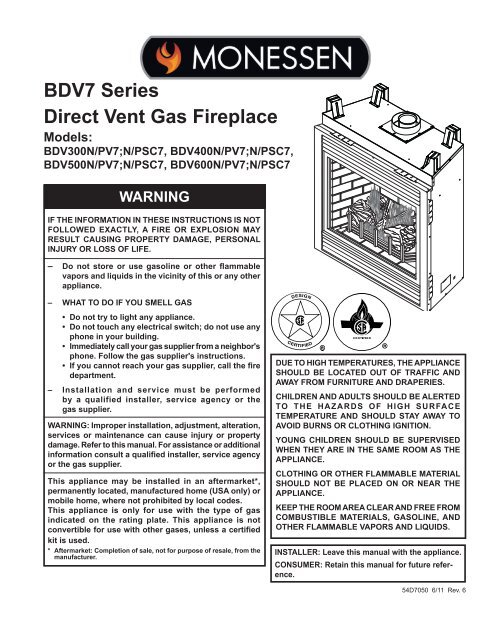
<strong>BDV7</strong> <strong>Series</strong><br />
<strong>Direct</strong> <strong>Vent</strong> <strong>Gas</strong> <strong>Fireplace</strong><br />
Models:<br />
BDV300N/PV7;N/PSC7, BDV400N/PV7;N/PSC7,<br />
BDV500N/PV7;N/PSC7, BDV600N/PV7;N/PSC7<br />
WARNING<br />
IF the INFoRMAtIoN IN theSe INStRuCtIoNS IS Not<br />
FolloWeD exACtly, A FIRe oR exPloSIoN MAy<br />
ReSult CAuSING PRoPeRty DAMAGe, PeRSoNAl<br />
INjuRy oR loSS oF lIFe.<br />
– Do not store or use gasoline or other flammable<br />
vapors and liquids in the vicinity of this or any other<br />
appliance.<br />
– WhAt to Do IF you SMell GAS<br />
• Do not try to light any appliance.<br />
• Do not touch any electrical switch; do not use any<br />
phone in your building.<br />
• Immediately call your gas supplier from a neighbor's<br />
phone. Follow the gas supplier's instructions.<br />
• If you cannot reach your gas supplier, call the fire<br />
department.<br />
– Installation and service must be performed<br />
by a qualified installer, service agency or the<br />
gas supplier.<br />
WARNING: Improper installation, adjustment, alteration,<br />
services or maintenance can cause injury or property<br />
damage. Refer to this manual. For assistance or additional<br />
information consult a qualified installer, service agency<br />
or the gas supplier.<br />
this appliance may be installed in an aftermarket*,<br />
permanently located, manufactured home (uSA only) or<br />
mobile home, where not prohibited by local codes.<br />
this appliance is only for use with the type of gas<br />
indicated on the rating plate. this appliance is not<br />
convertible for use with other gases, unless a certified<br />
kit is used.<br />
* Aftermarket: Completion of sale, not for purpose of resale, from the<br />
manufacturer.<br />
547050<br />
DVB7 cover<br />
Due to hIGh teMPeRAtuReS, the APPlIANCe<br />
ShoulD Be loCAteD out oF tRAFFIC AND<br />
AWAy FRoM FuRNItuRe AND DRAPeRIeS.<br />
ChIlDReN AND ADultS ShoulD Be AleRteD<br />
to the hAZARDS oF hIGh SuRFACe<br />
teMPeRAtuRe AND ShoulD StAy AWAy to<br />
AVoID BuRNS oR ClothING IGNItIoN.<br />
youNG ChIlDReN ShoulD Be SuPeRVISeD<br />
WheN they ARe IN the SAMe RooM AS the<br />
APPlIANCe.<br />
ClothING oR otheR FlAMMABle MAteRIAl<br />
ShoulD Not Be PlACeD oN oR NeAR the<br />
APPlIANCe.<br />
KeeP the RooM AReA CleAR AND FRee FRoM<br />
CoMBuStIBle MAteRIAlS, GASolINe, AND<br />
otheR FlAMMABle VAPoRS AND lIquIDS.<br />
INStAlleR: leave this manual with the appliance.<br />
CoNSuMeR: Retain this manual for future reference.<br />
54D7050 6/11 Rev. 6
<strong>BDV7</strong> <strong>Series</strong> <strong>Direct</strong> <strong>Vent</strong> <strong>Gas</strong> <strong>Fireplace</strong><br />
thank you and congratulations on your purchase of a<br />
Important Safety Information ...................................3<br />
Code Approval ...........................................................4<br />
Product Features .......................................................5<br />
High Elevations .....................................................5<br />
<strong>Gas</strong> Pressures ......................................................5<br />
<strong>Gas</strong> Specifications & Orifices ................................5<br />
Pre-Installation Information<br />
Before You Start ....................................................5<br />
<strong>Fireplace</strong> & Framing Dimensions ..........................6<br />
<strong>Fireplace</strong> Location .................................................7<br />
Clearances .................................................................8<br />
Secure <strong>Fireplace</strong> to Floor or Framing......................9<br />
optional top <strong>Vent</strong> Application ................................10<br />
<strong>Vent</strong> Installation ....................................................... 11<br />
Installation Precautions ....................................... 11<br />
Termination Location ...........................................1<br />
General Information Assembly <strong>Vent</strong> Pipes .......... 13<br />
<strong>Vent</strong> Graph ..........................................................14<br />
Rear Wall <strong>Vent</strong> Applications & Installation .......... 16<br />
Top <strong>Vent</strong> Sidewall Applications & Installation ...... 17<br />
Below Grade Installation ..................................... 1<br />
Vertical Through-the-Roof Installation .................<br />
<strong>Fireplace</strong> Installation ...............................................24<br />
Check <strong>Gas</strong> Type.................................................. 4<br />
Installing <strong>Gas</strong> Piping to <strong>Fireplace</strong>/Burner System<br />
Location .............................................................. 4<br />
Check <strong>Gas</strong> Pressure - Millivolt ..............................26<br />
electrical Installation...............................................27<br />
Electrical Wiring .................................................. 7<br />
Remote Wall Switch Installation ............................27<br />
optional Fan/Blower Systems - Millivolt ............... 28<br />
operating Instructions - Millivolt ...........................29<br />
Lighting Pilot for the First Time ........................... 9<br />
Lighting Pilot .......................................................30<br />
Lighting Burner ....................................................31<br />
To Turn Off <strong>Gas</strong> ...................................................31<br />
Monessen <strong>Fireplace</strong>.<br />
CoNteNtS<br />
PleASe ReAD the INStAllAtIoN AND oPeRAtIoN INStRuCtIoNS BeFoRe uSING the APPlIANCe!<br />
IMPoRtANt: Read all instructions and warnings carefully before starting installation.<br />
Failure to follow these instructions may result in a possible fire hazard and will void the warranty.<br />
Check <strong>Gas</strong> Pressure -<br />
Signature Command System ..........................32<br />
electrical Wiring -<br />
Signature Command System ..........................33<br />
Junction Box Wiring ............................................33<br />
Command Center Wall Installation ......................33<br />
Wall Switch Installation .......................................33<br />
Signature Command Wiring Diagram .................34<br />
optional Fan/Blower Systems ................................35<br />
BLOTSC Signature Command System ...............35<br />
BLOT Automatic Thermostat Blower ...................36<br />
FK-1 Manual Blower .........................................36<br />
operating Instructions -<br />
Signature Command System ...........................37<br />
Operating Instructions .........................................38<br />
To Turn Off <strong>Gas</strong> To Appliance .............................38<br />
Signature Command System operation................39<br />
Glass Removal .........................................................42<br />
Final Installation ......................................................43<br />
Rockwool Placement ..........................................43<br />
Log Placement ....................................................43<br />
Cleaning and Maintenance .....................................44<br />
Burner, Pilot and Control Compartment .............. 44<br />
Pilot Flame ..........................................................44<br />
Burner Flame ......................................................44<br />
<strong>Vent</strong> System ........................................................45<br />
Glass Door ..........................................................45<br />
Logs ....................................................................45<br />
Rock Wool ..........................................................45<br />
troubleshooting ......................................................46<br />
Standing Pilot Ignition .........................................46<br />
Signature Command System ..............................48<br />
Replacement Parts ..................................................49<br />
Firebox Components ...........................................49<br />
Standing Pilot Millivolt Control ...........................51<br />
Signature Command System ..............................53<br />
Logs ....................................................................55<br />
Vertical <strong>Vent</strong>ing Components ..............................56<br />
Horizontal <strong>Vent</strong>ing Components .........................57<br />
Massachusetts Residents only..............................62<br />
Warranty ...................................................................63<br />
efficiencies...............................................................64<br />
54D7050
IMPoRtANt SAFety INFoRMAtIoN<br />
INStAlleR<br />
Please leave these instructions with the appliance.<br />
WARNING<br />
oWNeR<br />
<strong>BDV7</strong> <strong>Series</strong> <strong>Direct</strong> <strong>Vent</strong> <strong>Gas</strong> <strong>Fireplace</strong><br />
Please retain these instructions for future reference.<br />
• Read this owner’s manual carefully and completely before trying to assemble, operate,<br />
or service this fireplace.<br />
• Any change to this fireplace or its controls can be dangerous.<br />
• Improper installation or use of this fireplace can cause serious injury or death from<br />
fire, burns, explosions, electrical shock and carbon monoxide poisoning.<br />
This fireplace is a vented product. This fireplace must be<br />
properly installed by a qualified service person. The glass<br />
door must be properly seated and sealed. If this unit is not<br />
properly installed by a qualified service person with glass<br />
door properly seated and sealed, combustion leakage<br />
can occur.<br />
CARBoN MoNoxIDe PoISoNING: Early signs of carbon<br />
monoxide poisoning are similar to the flu with headaches,<br />
dizziness and/or nausea. If you have these signs, the fireplace<br />
may not have been installed properly. Get fresh air<br />
at once! Have the fireplace inspected and serviced by a<br />
qualified service person. Some people are more affected<br />
by carbon monoxide than others. These include pregnant<br />
women, people with heart or lung disease or anemia,<br />
those under the influence of alcohol, and those at high<br />
altitudes.<br />
Propane/LP gas and natural gas are both odorless. An<br />
odor-making agent is added to each of these gases. The<br />
odor helps you detect a gas leak. However, the odor added<br />
to these gases can fade. <strong>Gas</strong> may be present even though<br />
no odor exists.<br />
Make certain you read and understand all warnings. Keep<br />
this manual for reference. It is your guide to safe and proper<br />
operation of this fireplace.<br />
1. This appliance is only for use with the type of gas<br />
indicated on the rating plate. This appliance is not<br />
convertible for use with other gases unless a certified<br />
kit is used.<br />
. For propane/LP fireplace, do not place propane/LP<br />
supply tank(s) inside any structure. Locate propane/<br />
LP supply tank(s) outdoors. To prevent performance<br />
problems, do not use propane/LP fuel tank of less than<br />
100 lbs. capacity.<br />
3. If you smell gas<br />
• shut off gas supply.<br />
• do not try to light any appliance.<br />
• do not touch any electrical switch; do not use any<br />
phone in your building .<br />
• immediately call your gas supplier from a neighbor’s<br />
phone. Follow the gas supplier’s instructions.<br />
4. Never install the fireplace<br />
• in a recreational vehicle<br />
• where curtains, furniture, clothing, or other flammable<br />
objects are less than 4 " from the front, top,<br />
or sides of the fireplace<br />
• in high traffic areas<br />
• in windy or drafty areas<br />
5. This fireplace reaches high temperatures. Keep children<br />
and adults away from hot surfaces to avoid burns<br />
or clothing ignition. <strong>Fireplace</strong> will remain hot for a time<br />
after shutdown. Allow surfaces to cool before touching.<br />
6. Young children should be carefully supervised when<br />
they are in the same room as the appliance. Toddlers,<br />
young children and others may be susceptible to<br />
accidental contact burns. A physical barrier is recommended<br />
if there are at risk individuals in the house. To<br />
restrict access to a fireplace or stove, install an adjustable<br />
safety gate to keep toddlers, young children and<br />
other at risk individuals out of the room and away from<br />
hot surfaces.<br />
7. Do not modify fireplace under any circumstances. Any<br />
parts removed for servicing must be replaced prior to<br />
operating fireplace.<br />
8. Turn fireplace off and let cool before servicing, installing,<br />
or repairing. Only a qualified service person should<br />
install, service, or repair the fireplace. Have burner<br />
system inspected annually by a qualified service<br />
person.<br />
9. You must keep control compartments, burners, and<br />
circulating air passages clean. More frequent cleaning<br />
may be needed due to excessive lint and dust.<br />
Turn off the gas valve and pilot light before cleaning<br />
fireplace.<br />
10. Have venting system inspected annually by a qualified<br />
service person. If needed, have venting system<br />
cleaned or repaired. Refer to Cleaning and Maintenance,<br />
Page 44.<br />
11. Keep the area around your fireplace clear of combustible<br />
materials, gasoline, and other flammable vapor<br />
and liquids. Do not run fireplace where these are used<br />
or stored. Do not place items such as clothing or decorations<br />
on or around fireplace.<br />
54D7050 3
<strong>BDV7</strong> <strong>Series</strong> <strong>Direct</strong> <strong>Vent</strong> <strong>Gas</strong> <strong>Fireplace</strong><br />
1 . Do not use this fireplace to cook food or burn paper or<br />
other objects.<br />
13. Never place anything on top of fireplace.<br />
14. Do not use any solid fuels (wood, coal, paper, cardboard,<br />
etc.) in this fireplace. Use only the gas type<br />
indicated on rating plate.<br />
15. This appliance, when installed, must be electrically<br />
grounded in accordance with local codes or in the<br />
absence of local codes, with the National Electrical<br />
Code, ANSI/NFPA 70, or the Canadian Electrical Code,<br />
CSA C .1.<br />
16. Do not obstruct the flow of combustion and ventilation<br />
air in any way. Provide adequate clearances around<br />
air openings into the combustion chamber along with<br />
adequate accessibility clearance for servicing and<br />
proper operation.<br />
17. When the appliance is installed directly on carpeting,<br />
tile or other combustible material other than wood<br />
flooring, you must set appliance on a metal or wood<br />
panel or hearth pad extending the full width and depth<br />
of the appliance.<br />
18. Do not use fireplace if any part has been exposed to<br />
or has been under water. Immediately call a qualified<br />
service technician to inspect the appliance and replace<br />
any part of the control system and any gas control<br />
which as been submerged in water.<br />
19. Do not operate fireplace if any log is broken.<br />
0. Do not use a blower insert, heat exchanger insert, or<br />
any other accessory not approved for use with this<br />
fireplace.<br />
1. Do not operate the fireplace with glass door removed,<br />
cracked, or broken.<br />
CoDe APPRoVAl<br />
<strong>Direct</strong> <strong>Vent</strong> type appliances draw all combustion air from<br />
outside of the dwelling through the vent pipe.<br />
These appliances have been tested by CSA and found to<br />
comply with the established standards for DIRECT VENT<br />
GAS FIREPLACE HEATERS in the USA and Canada as<br />
follows:<br />
lISteD VeNteD GAS FIRePlACe heAteR<br />
TESTED TO:<br />
ANSI Z 1.88B- 009 / CSA .33- 009 STANDARDS<br />
IMPoRtANt SAFety INFoRMAtIoN<br />
IMPoRtANt:<br />
PleASe ReAD the FolloWING<br />
CAReFully<br />
It is normal for fireplaces fabricated of steel to give off<br />
some expansion and/or contraction noises during the<br />
start up or cool down cycle. Similar noises are found<br />
with your furnace heat exchanger or car engine.<br />
IMPoRtANt:<br />
PleASe ReAD the FolloWING<br />
CAReFully<br />
It is not unusual for gas fireplaces to give off some<br />
odor the first time it is burned. This is due to the<br />
manufacturing process.<br />
Please ensure that your room is well ventilated<br />
during burn off — open all windows.<br />
It is recommended that you burn your fireplace for at<br />
least ten (10) hours the first time you use it. Place the<br />
fan switch in the “OFF” position during this time.<br />
WARNING<br />
Never connect unit to private (nonutility)<br />
gas wells. this gas is commonly<br />
known as wellhead gas.<br />
WARNING<br />
A manufactured home (USA only) or mobile home OEM<br />
HOT GLASS WILL<br />
installation must conform with the Manufactured Home<br />
Nous recommandons CAUSE BURNS. que nos<br />
Construction and Safety Standard, title 24 CFR, Part<br />
appareils de chauffage au gaz<br />
3280, or when such a standard is not applicable, the<br />
DO NOT TOUCH GLASS<br />
soient installés et entretenus par<br />
Standard for Manufactured home Installations, ANSI/<br />
UNTIL COOLED.<br />
des professionnels qui ont été<br />
NCSBCS A225.1, or Standard for <strong>Gas</strong> equipped Recre-<br />
NEVER ALLOW CHILDREN<br />
accrédités aux È.U. par le National<br />
ational Vehicles and Mobile housing, CSA Z240.4.<br />
TO TOUCH GLASS.<br />
<strong>Fireplace</strong> Institute ® (NFI) comme<br />
étant des spécialistes du NFI en<br />
matièred’appareils de chauffage<br />
4 54D7050<br />
au gaz.<br />
!
PRoDuCt FeAtuReS and GAS SPeCIFICAtIoNS<br />
PRoDuCt SPeCIFICAtIoNS<br />
• This appliance has been certified for use with either<br />
natural or propane gas. Refer to appropriate data<br />
plates.<br />
• This appliance is not for use with solid fuels.<br />
• The appliance is approved for bedroom or bedsitting<br />
room installations.<br />
• The appliance must be installed in accordance with local<br />
codes if any. If none exist use the current installation<br />
code. ANSI Z 3.1/NFPA 54 in the USA, CSA B149 in<br />
Canada.<br />
• This appliance is mobile home approved.<br />
• The appliance must be properly connected to a venting<br />
system.<br />
• The appliance is not approved for closet or recessed<br />
installations.<br />
Hi/Lo Knob<br />
Off/Pilot/On Knob<br />
On/Off/RS Switch<br />
Ignitor<br />
Blower Control<br />
Figure 1 -<br />
BDV300/400/500/600 <strong>Fireplace</strong><br />
(Millivolt Control Shown)<br />
hIGh eleVAtIoNS<br />
Optional Remote<br />
Receiver<br />
FP 087<br />
Input ratings are shown in BTU per hour and are certified<br />
without deration for elevations up to 4,500 feet (1,370<br />
m) above sea level.<br />
For elevations above FP2087 4,500 feet (1,370 m) in USA,<br />
installation must be in DVB accordance features with the current<br />
ANSI Z 3.1/NFPA 54 and/or local codes having jurisdiction.<br />
In Canada, please consult provincial and/or local<br />
authorities having jurisdiction for installation at elevations<br />
above 4,500 feet (1,370 m).<br />
GAS PReSSuReS<br />
Natural Propane (LP)<br />
Inlet Minimum 4.5” w.c. 11.0” w.c.<br />
Inlet Maximum 10.5” w.c. 13.0” w.c.<br />
Manifold Pressure 3.5” w.c. 10.0” w.c.<br />
<strong>BDV7</strong> <strong>Series</strong> <strong>Direct</strong> <strong>Vent</strong> <strong>Gas</strong> <strong>Fireplace</strong><br />
GAS SPeCIFICAtIoNS & oRIFICe SIZe<br />
Max.Input Min. Input Orifice<br />
Model Fuel BTU/h BTU/h Size<br />
BDV300NV7 Nat. 1,000 15,000 #43<br />
BDV300PV7 LP 1,000 15,000 #54<br />
BDV300NSC7 Nat. 1,000 15,000 #43<br />
BDV300NPC7 LP 1,000 15,000 #54<br />
BDV400NV7 Nat. 4,000 17,000 #41<br />
BDV400PV7 LP 4,000 17,000 #53<br />
BDV400NSC7 Nat. 4,000 17,000 #41<br />
BDV400NPC7 LP 4,000 17,000 #53<br />
BDV500NV7 Nat. 6,000 0,000 #40<br />
BDV500PV7 LP 6,000 0,000 1.55 mm<br />
BDV500NSC7 Nat. 6,000 0,000 #40<br />
BDV500PSC7 LP 6,000 0,000 1.55 mm<br />
BDV600NV7 Nat. 6,000 0,000 #40<br />
BDV600PV7 LP 6,000 0,000 1.55 mm<br />
BDV600NSC7 Nat. 6,000 0,000 #40<br />
BDV600PSC7 LP 6,000 0,000 1.55 mm<br />
BeFoRe you StARt<br />
Read this homeowner manual thoroughly and follow all<br />
instructions carefully. Inspect all contents for shipping<br />
damage and immediately inform your dealer if any damage<br />
is found. Do not install any unit with damaged, incomplete,<br />
or substitute parts. Check your packing list to verify that<br />
all listed parts have been received. You should have the<br />
following:<br />
• <strong>Fireplace</strong> (Firebox and Burner System)<br />
• Rock Wool<br />
• Log Set<br />
IteMS RequIReD FoR INStAllAtIoN<br />
• Phillips Screwdriver • Framing Materials<br />
• Hammer • Wall Finishing Materials<br />
• Saw and/or saber saw • Level<br />
• Electric Drill and Bits • Tee Joint<br />
• Pliers • Measuring Tape<br />
• Square • Pipe Wrench<br />
• Caulking Material (Noncombustible)<br />
• <strong>Fireplace</strong> Surround Material (Noncombustible)<br />
• Piping Complying with Local Codes<br />
• Pipe Sealant Approved for use with Propane/LPG<br />
(Resistant to Sulfur Compounds)<br />
54D7050 5
<strong>BDV7</strong> <strong>Series</strong> <strong>Direct</strong> <strong>Vent</strong> <strong>Gas</strong> <strong>Fireplace</strong><br />
S<br />
T<br />
Figure 2 -<br />
<strong>Fireplace</strong> and Framing Dimensions<br />
S<br />
R<br />
Min. Rough<br />
Opening<br />
Depth<br />
Q<br />
H<br />
Min. Rough<br />
Opening<br />
Height<br />
P<br />
1/2” 5/8”<br />
FIRePlACe DIMeNSIoNS<br />
BDV300 BDV400 BDV500 BDV600<br />
A 33Z\zn” (840 mm) 37Z\zn” (941 mm) 41Z\zn” (1043 mm) 47Z\zn” (1195 mm)<br />
B 9M\,” (759 mm) 3 ” (813 mm) 36” (914 mm) 4 ” (1067 mm)<br />
C 7” (686 mm) 9” (737 mm) 33” (838 mm) 39” (991 mm)<br />
D<br />
E<br />
16Z\x”<br />
8”<br />
(419 mm)<br />
(711 mm)<br />
544050<br />
18Z\x” (470 mm)<br />
DVB/<strong>BDV7</strong> dims<br />
9” (737 mm)<br />
0Z\x” (5 1mm)<br />
33” (838 mm)<br />
3Z\x” (597 mm)<br />
39” (991 mm)<br />
F 18” (457 mm) 0C\,” (518 mm) 0C\,” (518 mm) 0C\,” (518 mm)<br />
G 33M\,” (860 mm) 37Z\x” (953 mm) 37Z\x” (953 mm) 37Z\x” (953 mm)<br />
H 14” (357 mm) 16” (406 mm) 16” (406 mm) 16” (406 mm)<br />
I 37M\,” (96 mm) 41Z\x” (1054 mm) 41Z\x” (1054 mm) 41Z\x” (1054 mm)<br />
J 9B\,” (753 mm) 33Z\,” (841 mm) 33Z\,” (841 mm) 33Z\,” (841 mm)<br />
K Z\,” (54 mm) 1Z\v” (3 mm) 1Z\v” (3 mm) 1Z\v” (3 mm)<br />
L 1Z\x” (38 mm) Z\x” (64 mm) Z\x” (64 mm) Z\x” (64 mm)<br />
M 15/16” ( 4 mm) 15/16” ( 4 mm) 15/16” ( 4 mm) 15/16” ( 4 mm)<br />
N 31B\,” (803 mm) 34C\v” (883 mm) 34C\v” (883 mm) 34C\v” (883 mm)<br />
O 33Z\x” (851 mm) 37Z\x” (953 mm) 41Z\x” (1054 mm) 47Z\x” (1 07 mm)<br />
P 38” (966 mm) 41B\,” (1057 mm) 41B\,” (1057 mm) 41B\,” (1057 mm)<br />
Q 13C\v” (349 mm) 15C\v” (400 mm) 15C\v” (400 mm) 15C\v” (400 mm)<br />
R 55ZZ\zn” (1414 mm) 60M\,” (1546 mm) 64M\,” (1648 mm) 70M\,” (1800 mm)<br />
S 39C\,” (1000 mm) 43Z\zn” (1094 mm) 45M\,” (1165 mm) 50Z\,” (1 73 mm)<br />
T 7ZC\zn” (706 mm) 30M\zn” (773 mm) 3 M\zn” (8 4 mm) 35M\zn” (900 mm)<br />
6 54D7050<br />
M<br />
L<br />
E<br />
C<br />
B<br />
A<br />
D<br />
5/8” 1/2”<br />
O - Min. Rough Opening Width<br />
K<br />
F<br />
G<br />
N I<br />
1/2” or 5/8”<br />
3���”<br />
1/2”<br />
8���”<br />
5/8"<br />
J
PRe-INStAllAtIoN INFoRMAtIoN<br />
FIReBox FRAMING<br />
Firebox framing can be built before or after the appliance<br />
is set in place. Refer to Figure 2 for fireplace and framing<br />
dimensions. Construct firebox framing following Figure 2<br />
for your specific installation requirements. The framing<br />
headers may rest on the top of the firebox standoffs. Do<br />
not bring headers below top of standoffs.<br />
The firebox may be installed directly on a combustible floor<br />
or raised on a platform of an appropriate height. When<br />
the firebox is installed directly on carpeting, tile, or other<br />
combustible material, other than wood flooring, the firebox<br />
shall be installed on a metal or wood panel extending the<br />
full width and depth of the enclosure.<br />
FIRePlACe loCAtIoN<br />
Plan for the installation of your appliance. This includes<br />
determining where the unit is to be installed, the vent configuration<br />
to be used, framing and finishing details, and<br />
whether any optional accessories (i.e. blower, wall switch,<br />
or remote control) are desired. Consult your local building<br />
code agency to ensure compliance with local codes, including<br />
permits and inspections.<br />
The following factors should be taken into consideration:<br />
• Clearance to side-wall, ceiling, woodwork, and windows.<br />
Minimum clearances to combustibles must be maintained.<br />
• This fireplace may be installed along a wall, across a<br />
corner, or use an exterior chase. Refer to Figure 3 for<br />
suggested locations.<br />
• Location should be out of high traffic areas and away<br />
from furniture and draperies due to heat from appliance.<br />
• Never obstruct the front opening of the fireplace.<br />
• Do not install in the vicinity where gasoline or other<br />
flammable liquids may be stored.<br />
• <strong>Vent</strong> pipe routing. Refer to <strong>Vent</strong>ing section found in this<br />
manual for allowable venting configurations.<br />
• These units can be installed in a bedroom. See National<br />
Fuel <strong>Gas</strong> Code ANSI Z 33.1/NFPA 54 — (current<br />
edition), the Uniform Mechanical Code — (current edition),<br />
and Local Building Codes for specific installation<br />
requirements.<br />
Note<br />
<strong>BDV7</strong> <strong>Series</strong> <strong>Direct</strong> <strong>Vent</strong> <strong>Gas</strong> <strong>Fireplace</strong><br />
54D7050 7<br />
WARNING<br />
Y<br />
Y<br />
Do not fill spaces around firebox with<br />
insulation or other materials. this could<br />
cause a fire.<br />
E A<br />
D<br />
F<br />
Figure 3 -<br />
<strong>Fireplace</strong> Locations<br />
C<br />
X<br />
B<br />
B<br />
A Flat on Wall<br />
LU584-1<br />
B Cross Corner<br />
Locating unit<br />
C Island**<br />
2/4/99 djt<br />
D Room Divider*<br />
E Flat on Wall Corner*<br />
F Chase Installation<br />
Y 4” Minimum<br />
** Island (C) and room divider (D) installation is possible as long<br />
as the horizontal portion of vent system (X) does not exceed<br />
0'. Refer to Termination Location on Pages 12 and 13.<br />
* When you install your fireplace in (D) room divider or (E)<br />
flat on wall corner positions (Y), a minimum of 6" clearance<br />
must be maintained from perpendicular wall and front of<br />
fireplace.<br />
ColD ClIMAte INSulAtIoN<br />
If you live in a cold climate, seal all cracks around your appliance, and<br />
wherever cold air could enter the room, with noncombustible material. It<br />
is especially important to insulate the outside chase cavity between the<br />
studs and under the floor on which the appliance rests, if the floor is above<br />
ground level.
<strong>BDV7</strong> <strong>Series</strong> <strong>Direct</strong> <strong>Vent</strong> <strong>Gas</strong> <strong>Fireplace</strong><br />
CleARANCeS to CoMBuStIBleS<br />
WARNING<br />
Follow these instructions carefully to ensure safe installation. Failure<br />
to follow instructions exactly can create a fire hazard.<br />
the appliance cannot be installed on a carpet, tile or other combustible<br />
material other than wood flooring. If installed on carpet or vinyl flooring,<br />
the appliance shall be installed on a metal, wood or noncombustible<br />
material panel extending full width and depth of the appliance.<br />
Ceiling<br />
71” Minimum<br />
Figure 4 -<br />
Clearances<br />
Min. 4”<br />
From Either<br />
Side Wall<br />
MANtel CleARANCeS<br />
Combustible Mantel<br />
11” Minimum<br />
12”<br />
Max.<br />
Note: The combustible area above the facing must<br />
not protrude more than 1/ " from the facing. If it does,<br />
it is considered a mantel and must meet the mantel<br />
requirements listed in this manual.<br />
FP2248<br />
Note: The <strong>MHSC</strong> Barrington mantel Cabinet clearances Mantel Model series<br />
BWC300, BWC400 and BWC500 are specially designed<br />
to comply with all mantel temperature requirements. Any<br />
custom-built mantel must comply with all clearance requirements<br />
shown in this instruction manual.<br />
CleARANCeS<br />
8 54D7050<br />
WARNING<br />
11”<br />
12”<br />
7”<br />
5”<br />
Wall<br />
Top of Exhaust<br />
Louvers<br />
FP 093a<br />
Side of <strong>Fireplace</strong><br />
Opening<br />
8”<br />
6”<br />
3”<br />
2”<br />
Side View<br />
Stud<br />
FP2204a<br />
mantel clearances Combustible<br />
Material Area<br />
1"<br />
2���”<br />
3"<br />
Figure 5 -<br />
Mantel Clearances<br />
4"<br />
top View<br />
1���”<br />
Wall<br />
2���”<br />
Standoff<br />
FP 04a<br />
45°<br />
FP2093A<br />
Never<br />
mantel<br />
obstruct<br />
side clearance<br />
or modify the air inlet or<br />
outlet grilles (louvers). this may create<br />
a fire hazard.
SeCuRe FIRePlACe to FlooR or FRAMING<br />
The fireplace must be secured to the floor and/or to framing studs as shown in Figure 6. Use<br />
two ( ) wood screws or masonry/ concrete screws to secure fireplace to the floor. Use four (4)<br />
screws to attach fireplace to framing. The side nailing flanges are 1/ " or 5/8" to accommodate<br />
different wall thickness.<br />
Framing<br />
Nailing Flange<br />
Screws<br />
Nailing Flange<br />
Screws<br />
Figure 6 -<br />
Secure <strong>Fireplace</strong> to Floor and Framing Studs<br />
FINIShING MAteRIAl<br />
FP2094a<br />
Note: Any remote wiring (i.e. remote control, wall switch, and<br />
secure<br />
optional<br />
fireplace<br />
fan) must be done prior to<br />
final finishing to avoid costly reconstruction.<br />
Only noncombustible materials (i.e. brick, tile, slate, steel, or other materials with a UL fire rating<br />
of Zero) may be used to cover the black surface of the appliance. A 300°F minimum adhesive may<br />
be used to attach facing materials to the black surface. If joints between the finished wall and the<br />
fireplace surround are sealed, a 300°F minimum sealant material (General Electric RTV103 or<br />
equivalent) must be used.<br />
<strong>BDV7</strong> <strong>Series</strong> <strong>Direct</strong> <strong>Vent</strong> <strong>Gas</strong> <strong>Fireplace</strong><br />
Drywall Support Tabs<br />
(Do not use for framing or<br />
header)<br />
FP 094a<br />
Framing<br />
Nailing Flange<br />
Screws<br />
Nailing Flange<br />
54D7050 9
<strong>BDV7</strong> <strong>Series</strong> <strong>Direct</strong> <strong>Vent</strong> <strong>Gas</strong> <strong>Fireplace</strong><br />
oPtIoNAl toP VeNt APPlICAtIoN<br />
The appliance is shipped as a rear vent unit. If the installation<br />
layout requires the unit to be a top vent configuration<br />
the appliance can be converted by following the<br />
steps below.<br />
When removing and refitting the plates and adapter be<br />
sure the associated gaskets are undamaged and refitted<br />
as required.<br />
1. Remove the eight (8) screws securing the flue pipe<br />
adapter to the fireplace body. Figure 7<br />
. Set the flue pipe adapter aside, complete with the<br />
gasket. Do not damage the gaskets as the adapter<br />
and gasket must be refitted.<br />
3. Remove the eight (8) screws securing the flue pipe<br />
cover to the top of the intake box and remove the cover<br />
and gasket. Figure 7<br />
Flue Pipe<br />
Cover<br />
Flue Pipe<br />
Adapter<br />
Screws<br />
FP1991<br />
Figure 7 -<br />
Remove 16 Screws from Flue Pipe Adapter and Flue<br />
Pipe Cover<br />
4. Remove six (6) screws securing the flue pipe to the<br />
back of the intake box and remove the pipe and gasket.<br />
Figure 8<br />
5. Replace flue pipe to top of firebox. Ensure the gasket<br />
FP1991<br />
is in place and undamaged. Secure with six (6) screws.<br />
Figure 9 remove screws<br />
6. Place the flue pipe cover and gasket removed in step<br />
3 over the flue opening in back of the intake box.<br />
7. Refit the flue pipe adapter and gasket to the top of<br />
fireplace. Secure the adapter with eight (8) screws<br />
removed in Step 1.<br />
WARNING<br />
oPtIoNAl toP VeNt APPlICAtIoN<br />
After conversion to top vent configuration, the<br />
4” (102 mm) flue pipe should be concentric<br />
within the 6B\,” (175 mm) outer collar (within<br />
1/4”)<br />
Flue Pipe<br />
Figure 8 -<br />
Remove Flue Pipe<br />
Screws<br />
Flue Cover<br />
FP1992<br />
remove flue pipe<br />
Screws<br />
10 54D7050<br />
FP1993<br />
attach flue pipe<br />
Flue Pipe<br />
Figure 9 -<br />
Attach Flue Pipe to Top <strong>Vent</strong> Configurations<br />
FP199<br />
FP1993
VeNtING INStAllAtIoN INFoRMAtIoN<br />
WARNING<br />
INStAllAtIoN PReCAutIoNS<br />
Consult local building codes before beginning the<br />
installation. The installer must make sure to select the<br />
proper vent system for installation. Before installing vent<br />
kit, the installer must read this fireplace manual and vent<br />
kit instructions.<br />
Only a qualified installer/service person should install venting<br />
system. The installer must follow these safety rules:<br />
• Wear gloves and safety glasses for protection.<br />
• Use extreme caution when using ladders or when on<br />
rooftops.<br />
• Be aware of electrical wiring locations in walls and<br />
ceilings.<br />
The following actions will void the warranty on your venting<br />
system:<br />
• Installation of any damaged venting component.<br />
• Unauthorized modification of the venting system.<br />
• Installation of any component part not manufactured<br />
or approved by MHS.<br />
• Installation other than permitted by these instructions.<br />
WARNING WARNING<br />
this fireplace must be vented to the<br />
outside. the venting system must NeVeR<br />
be attached to a chimney serving a separate<br />
solid fuel burning appliance. each gas<br />
appliance must use a separate vent system.<br />
Do not use common vent systems.<br />
Always maintain minimum clearances around<br />
vent systems. the minimum clearances to<br />
combustibles for horizontal vent pipe are 3"<br />
at the top* and 1" at the sides and bottom<br />
of the vent system until the pipe penetrates<br />
the nearest vertical wall (1" required). A 1"<br />
minimum clearance all around the pipe must<br />
be maintained at outside wall and on vertical<br />
runs. Do not pack the open air spaces with<br />
insulation or other materials. this could<br />
cause high temperatures and may present<br />
a fire hazard.<br />
* unless the vertical run is 7Z\x feet or higher<br />
(top vent units only), the clearances for the<br />
horizontal run is 1" at the top.<br />
<strong>BDV7</strong> <strong>Series</strong> <strong>Direct</strong> <strong>Vent</strong> <strong>Gas</strong> <strong>Fireplace</strong><br />
Read all instructions completely and thoroughly before attempting installation. Failure<br />
to do so could result in serious injury, property damage or loss of life. operation of<br />
improperly installed and maintained venting system could result in serious injury,<br />
property damage or loss of life.<br />
GeNeRAl VeNtING<br />
Your fireplace is approved to be vented either through the<br />
side wall, or vertical through the roof.<br />
• only MhSC venting components specifically approved<br />
and labelled for this fireplace may be<br />
used.<br />
• Flexible UL1777 listed venting may be used in any<br />
venting application where rigid direct vent components<br />
can be used. All restrictions, clearances and allowances<br />
that pertain to the rigid piping apply to the flexible<br />
venting.<br />
Flex kits may not be modified. Flex kits may be added<br />
to the end of a vent run made of rigid vent sections<br />
using pipe manufacturer's approved flex to pipe adapters.<br />
This may occur only if doing so does not violate<br />
any of the venting length, height, routing, horizontal to<br />
vertical raito requirements or clearance considerations<br />
detailed in this manual.<br />
• <strong>Vent</strong>ing terminals shall not be recessed into a wall or<br />
siding.<br />
• Horizontal venting which incorporates the twist lock<br />
pipe must be installed on a level plane without an inclining<br />
or declining slope.<br />
• Horizontal venting which incorporates the use of flex<br />
venting shall have an inclining slope from the unit of 1”<br />
( 5 mm) per 4” (610 mm).<br />
There must not be any obstruction such as bushes, garden<br />
sheds, fences, decks or utility buildings within 4”<br />
(610 mm) from the front of the termination hood.<br />
Do not locate termination hood where excessive snow or<br />
ice build up may occur. Be sure to check vent termination<br />
area after snow falls, and clear to prevent accidental<br />
blockage of venting system. When using snow blowers,<br />
make sure snow is not directed towards vent termination<br />
area.<br />
location of <strong>Vent</strong> termination<br />
It is imperative the vent termination be located observing<br />
the minimum clearances as shown on following page.<br />
54D7050 11<br />
NotICe<br />
Failure to follow these instructions will<br />
void the warranty.
<strong>BDV7</strong> <strong>Series</strong> <strong>Direct</strong> <strong>Vent</strong> <strong>Gas</strong> <strong>Fireplace</strong><br />
GeNeRAl VeNtING INFoRMAtIoN - teRMINAtIoN loCAtIoN<br />
Figure 10 -<br />
Termination Locations<br />
L<br />
D<br />
V<br />
E<br />
B<br />
CFM145a<br />
F<br />
C<br />
V Fixed<br />
Closed<br />
V<br />
Operable<br />
B<br />
V<br />
A<br />
B B<br />
INSIDE<br />
CORNER DETAIL<br />
V<br />
B<br />
Fixed<br />
Operable<br />
Closed<br />
VeNtING INFoRMAtIoN<br />
1 54D7050<br />
V<br />
A<br />
J<br />
V VENT TERMINATION X AIR SUPPLY INLET AREA WHERE TERMINAL IS NOT PERMITTED<br />
Canadian Installations<br />
A = Clearance above grade, veranda, porch,<br />
CFM145a<br />
1 ” (30 cm) DV Termin Location<br />
1 ” (30 cm)<br />
deck, or balcony<br />
5/01/01 Rev. 12/05/01<br />
sta<br />
B = Clearance to window or door that may be 6” (15 cm) for appliances 6” (15 cm) for appliances<br />
opened < 10,000BTU/h (3kW), 1 ” (30 cm) < 10,000 BTU/h (3kW), 9”<br />
for appliances > 10,000 Btuh (3kW) and ( 3 cm) for appliances > 10,000<br />
< 100,000 BTU/h (30kW), 36” (91 cm) Btuh (3kW) and < 50,000 BTU/h<br />
for appliances > 100,000 BTU/h (30kW) (15kW), 1 ” (30 cm) for<br />
appliances > 50,000 BTU/h(15kW)<br />
C = Clearance to permanently closed window 1 ” (305 mm) recommended to 1 ” (305 mm) recommended to<br />
D = Vertical clearance to ventilated soffit located<br />
prevent window condensation prevent window condensation<br />
above the terminal within a horizontal<br />
distance of ’ (610mm) from the center<br />
line of the terminal<br />
18” (458 mm) 18” (458 mm)<br />
E = Clearance to unventilated soffit 1 ” (305 mm) 1 ” (305 mm)<br />
F = Clearance to outside corner see next page see next page<br />
G = Clearance to inside corner (see next page) see next page see next page<br />
H = Clearance to each inside of center line 3’ (91 cm) within a height of 15’ (5 m) 3’ (91 cm) within a height of 15’<br />
extended above meter/regulator assembly above the meter/regulator assembly (5 m) above the meter/regulator<br />
assy<br />
I = Clearance to service regulator vent outlet 3’ (91 cm) 3’ (91 cm)<br />
J = Clearance to nonmechanical air supply inlet 6” (15 cm) for appliances < 10,000 6” (15 cm) for appliances<br />
to building or the combustion air inlet to any BTU/h (3kW), 1 ” (30 cm) for < 10,000 BTU/h (3kW), 9”<br />
other appliances appliances > 10,000 BTU/h (3kW) and ( 3 cm) for appliances > 10,000<br />
< 100,000 Btuh (30kW), 36” (91 cm) BTU/h (3kW) and < 50,000 BTU/h<br />
for appliances > 100,000 BTU/h (30kW) (15kW), 1 ” (30 cm) for<br />
appliances > 50,000 BTU/h(15kW)<br />
K = Clearance to a mechanical air supply inlet 6’ (1.83 m) 3’ (91 cm) above if within 10'<br />
(3 m) horizontally<br />
L = Clearance above paved sidewalk or paved<br />
driveway located on public property<br />
7’ ( .13 m)† 7’ ( .13 m)†<br />
M = Clearance under veranda, porch, deck or<br />
balcony<br />
1 ” (30 cm) 1 ” (30cm)<br />
1 uS Installations2 1 In accordance with the current CSA-B149 Installation Codes<br />
In accordance with the current ANSI Z 3.1/NFPA 54 National Fuel<br />
<strong>Gas</strong> Codes<br />
† A vent shall not terminate directly above a sidewalk or paved<br />
driveway which is located between two single family<br />
dwellings and serves both dwellings<br />
only permitted if veranda, porch, deck or balcony is fully open on a<br />
minimum sides beneath the floor:<br />
G<br />
V<br />
B<br />
X<br />
H<br />
I<br />
M<br />
NOTE: 1. Local codes or regulations may require different<br />
clearances.<br />
. The special venting system used on <strong>Direct</strong> <strong>Vent</strong> <strong>Fireplace</strong>s<br />
are certified as part of the appliance, with clearances<br />
tested and approved by the listing agency.<br />
3. <strong>MHSC</strong> assumes no responsibility for the improper<br />
performance of the appliance when the venting system<br />
does not meet these requirements.<br />
V<br />
K<br />
X
VeNtING INFoRMAtIoN<br />
Termination Clearances<br />
Termination clearances for buildings with combustible and noncombustible exteriors.<br />
Inside Corner<br />
Outside Corner<br />
Alcove Applications*<br />
G<br />
V<br />
Balcony -<br />
with no side wall<br />
M =<br />
Combustible &<br />
Noncombustible<br />
12" (305 mm)<br />
G =<br />
Combustible<br />
6" (152 mm)<br />
Noncombustible<br />
2" (51 mm)<br />
M<br />
V<br />
V<br />
Balcony -<br />
with perpendicular side wall<br />
M<br />
F<br />
Combustible &<br />
Noncombustible<br />
M = 24" (610 mm)<br />
P = 20” (508 mm)<br />
V<br />
F =<br />
Combustible<br />
6" (152 mm)<br />
Noncombustible<br />
2" (51 mm)<br />
P<br />
<strong>BDV7</strong> <strong>Series</strong> <strong>Direct</strong> <strong>Vent</strong> <strong>Gas</strong> <strong>Fireplace</strong><br />
54D7050 13<br />
C<br />
O<br />
D<br />
V<br />
E<br />
C<br />
E = Min. 6” (152 mm) for<br />
non-vinyl sidewalls<br />
Min. 12” (305 mm) for<br />
vinyl sidewalls<br />
O = 8’ (2.4 m) Min.<br />
No.<br />
of Caps D Min. C Max.<br />
1 3’ (914 mm) x D Actual<br />
6’ (1.8 m) 1 x D Actual<br />
3 9’ ( .7 m) /3 x D Actual<br />
4 1 ’ (3.7 m) 1/ x D Actual<br />
D Min. = # of Termination caps x 3<br />
C Max. = ( / # termination caps) x D Actual<br />
*Note: Termination in an alcove space (spaces open only on one side and with an overhang) is permitted with the dimensions specified for vinyl or<br />
non-vinyl siding and soffits. 1. There must be a 3’ (914 mm) minimum between termination caps. . All mechanical air intakes within 10’ (1 m) of a<br />
termination cap must be a minimum of 3’ (914 mm) below the termination cap. 3. All gravity air intakes within 3’ (914 mm) of a termination cap must<br />
be a minimum of 1’ (305 mm) below the termination cap. Figure 11 -<br />
Termination Clearances<br />
GeNeRAl INFoRMAtIoN ASSeMBlING VeNt PIPeS<br />
uSA Installations<br />
The venting system must conform to local codes and/or<br />
the current National Fuel Code ANSI Z 3.1/NFPA 54.<br />
Only venting components manufactured or approved by<br />
<strong>MHSC</strong> may be used in <strong>Direct</strong> <strong>Vent</strong> systems.<br />
Canadian Installations<br />
The venting system must be installed in accordance with<br />
the current CSA-B149.1 installation code.<br />
Flex <strong>Vent</strong> Pipes<br />
Secure flex vent pipe in place with a hose clamp (provided).<br />
*Be sure the flex pipe overlaps at least 1” ( 5 mm) onto<br />
the collars of the fireplace and termination. If the termination<br />
has an internal bead, be sure to overlap and secure<br />
1” ( 5 mm) past the bead.<br />
584-15<br />
* Be sure the vent is actually crushed before proceeding.<br />
Apply a tug to be sure the vent will not slip off the collars.<br />
Repeat process with 7” flex vent pipe. The same procedure<br />
must be performed on the vent side.<br />
FP 90<br />
Figure 12 -<br />
Secure Flex Pipe with hose Clamps<br />
Hose Clamp
<strong>BDV7</strong> <strong>Series</strong> <strong>Direct</strong> <strong>Vent</strong> <strong>Gas</strong> <strong>Fireplace</strong><br />
tWISt loCK PIPeS<br />
When using twist lock pipe it is not necessary to use sealant on the joints.<br />
To join twist lock pipes together, simply align the beads of the male end with the grooves of the female<br />
end, twisting the pipe until the flange on the female end contacts external flange on the male<br />
end. It is recommended that you secure the joints with three (3) sheet metal screws, however, this<br />
is not mandatory with twist lock pipe. Figure 13<br />
Note: Sealant is not required to assemble fireplace venting. Do not use silicone sealant at<br />
the inner flue exhaust connections.<br />
To make it easier to assembly the joints, we suggest putting a lubricant (Vaseline or similar) on the<br />
male end of the twist lock pipe prior to assembly.<br />
Male End Female End<br />
Screw Holes<br />
Figure 13 -<br />
Twist-lock Pipe Joints<br />
hoW to uSe the VeNt GRAPh<br />
TWL100<br />
TWL100<br />
Twist Lock Pipe<br />
The <strong>Vent</strong> Graph should 3/12/99 be djt read in conjunction with the<br />
following vent installation instructions to determine the relationship<br />
between the vertical and horizontal dimensions<br />
of the vent system.<br />
1. Determine the height of the center of the horizontal<br />
vent pipe exiting through the outer wall. Using this dimension<br />
on the Sidewall <strong>Vent</strong> Graph, Figure 14, locate<br />
the point intersecting with the slanted graph line.<br />
. From the point of this intersection, draw a vertical line<br />
to the bottom of the graph.<br />
3. Select the indicated dimension, and position the fireplace<br />
in accordance with same.<br />
exAMPle A:<br />
If the vertical dimension from the floor of the unit is 11’ (3.4<br />
m) the horizontal run to the face of the outer wall must not<br />
exceed 14’ (4.3 m).<br />
exAMPle B:<br />
If the vertical dimension from the floor of the unit is 7’ ( .1<br />
m), the horizontal run to the face of the outer wall must not<br />
exceed 8Z\x’ ( .6 m).<br />
Refer to Page 21 for requirements for snorkels.<br />
14 54D7050<br />
Vertical Dimension from the Floor of Unit to the Center of<br />
the Horizontal <strong>Vent</strong> Pipe<br />
20”<br />
40<br />
38<br />
36<br />
34<br />
32<br />
30<br />
28<br />
26<br />
24<br />
22<br />
20<br />
18<br />
16<br />
14<br />
12<br />
10<br />
8<br />
6<br />
4<br />
2<br />
eg: A<br />
2 4 6 8 10 12 14 16 18 20<br />
Horizontal Dimension From the Outside of Termination to<br />
the Back of the <strong>Fireplace</strong><br />
Figure 14 -<br />
Side Wall <strong>Vent</strong>ing Graph<br />
VeNtING INFoRMAtIoN<br />
FP2291<br />
vent graph
VeNt INStAllAtIoN<br />
WARNING<br />
horizontal sections of this vent system<br />
require a minimum of 3” clearances to<br />
combustibles at the top of the flue and 1”<br />
clearance at the sides and bottom until<br />
the flue penetrates the outside wall. A<br />
minimum 1” clearance all around the flue<br />
is acceptable at this point of penetration. If<br />
vertical rise is 7Z\x feet or higher when top<br />
venting, the clearance to combustibles is 1”<br />
on all sides of the horizontal run.<br />
Vertical sections of this vent system require<br />
a minimum of 1” clearance to combustibles<br />
on all sides of the pipe.<br />
*3”<br />
**1”<br />
**1”<br />
48”<br />
(1219 mm)***<br />
***44���” (1130 mm)<br />
for 300 <strong>Series</strong><br />
Figure 15 -<br />
Combustible Clearances for <strong>Vent</strong> Pipe<br />
<strong>BDV7</strong> <strong>Series</strong> <strong>Direct</strong> <strong>Vent</strong> <strong>Gas</strong> <strong>Fireplace</strong><br />
54D7050 15<br />
WARNING<br />
FP2095a<br />
vent pipe clearance<br />
this fireplace must be vented to the<br />
outside. the venting system must NeVeR<br />
be attached to a chimney serving a separate<br />
solid fuel burning appliance. each gas<br />
appliance must use a separate vent system.<br />
Do not use common vent systems.<br />
*3"<br />
FP 095a<br />
**1"<br />
**1"<br />
33���”<br />
(841 mm)***<br />
***29���" (753 mm)<br />
for 300 <strong>Series</strong><br />
* A Minimum 3” Clearance to the Top is<br />
Required Along Horizontal Length until<br />
Flue Pipe Penetrates Outside Wall<br />
** A Minimum 1” Clearance to Combustibles<br />
Permitted All Around Flue at Outside<br />
Wall
<strong>BDV7</strong> <strong>Series</strong> <strong>Direct</strong> <strong>Vent</strong> <strong>Gas</strong> <strong>Fireplace</strong><br />
ReAR WAll VeNt APPlICAtIoN<br />
When installed as a rear vent unit this appliance may be<br />
vented directly to a termination located on the rear wall<br />
behind the appliance.<br />
• Only <strong>MHSC</strong> venting components are approved to be<br />
used in these applications (Refer to ‘<strong>Vent</strong>ing Components’<br />
listed for different installation requirements).<br />
• The maximum horizontal distance between the rear of<br />
the appliance (or end of the transition elbow in a corner<br />
application) and the outside face of the rear wall is<br />
0” (508 mm). Figure 15<br />
• Only one 45° elbow is allowed in these installations.<br />
• Minimum clearances between vent pipe and combustible<br />
materials are as follows:<br />
Top - 3” (76 mm)<br />
- except at outside wall 1" ( 5 mm)<br />
Sides - 1” ( 5 mm)<br />
Bottom - 1” ( 5 mm)<br />
20”<br />
(508 mm)<br />
Max.<br />
Rear <strong>Vent</strong> top<br />
View<br />
Figure 16 -<br />
Rear <strong>Vent</strong> Appliaction, No Elbows<br />
20”<br />
(508 mm)<br />
Max.<br />
FP1188<br />
ReAR WAll VeNt INStAllAtIoN - tWISt<br />
loCK PIPe<br />
FP1188<br />
Step 1 rear wall install<br />
Locate and cut the vent opening in the wall.<br />
For combustible walls first frame in opening. Figure 17<br />
Note: When using flex vent, the opening will have to be<br />
measured according to the 1” ( 5 mm) rise in 4” (610<br />
mm) vertical run.<br />
Combustible Walls: Cut a 9B\,”H x 9B\,” W ( 44 x 44<br />
mm) hole through the exterior wall and frame as shown.<br />
Figure 17<br />
Noncombustible Walls: Hole opening should be 7Z\x”<br />
(191 mm) diameter.<br />
Step 2<br />
Secure firestop to the inside frame, center in the 9B\," x<br />
9B\," vent opening.<br />
9B\,”<br />
( 44 mm)<br />
Min.<br />
VeNtING INStAllAtIoN<br />
<strong>Vent</strong> opening for Combustible Walls<br />
9B\,”<br />
( 44 mm) Min.<br />
<strong>Fireplace</strong> Hearth<br />
Framing Detail<br />
opening for Noncombustible Wall<br />
7Z\x”<br />
(190 mm)<br />
Figure 17 -<br />
<strong>Fireplace</strong> Hearth<br />
Locate vent opening on wall.<br />
Step 3<br />
Measure the horizontal length requirement for the venting<br />
including a ” (51 mm) VO584-100 overlap, i.e. from the elbow to the<br />
outside wall face plus <strong>Vent</strong> ” (51 Opening mm). Figure 16<br />
Step 4 2/99 djt<br />
Install the 4” (10 mm) vent to the appliance collar and<br />
secure with 3 sheet metal screws. Install the 7” (178 mm)<br />
vent pipe to the appliance collar and secure with 3 sheet<br />
metal screws. It is not necessary to seal this connection.<br />
If a 45° elbow is being used attach the elbow to the appliance<br />
in the same manner then attach the venting to the<br />
elbow.<br />
It is critical that there is no downward slope<br />
away from the appliance when connecting<br />
the vent or elbow.<br />
Step 5<br />
Guide the venting through the vent hole as you place the<br />
appliance in its installed position. Guide the 4” (10 mm)<br />
and 7” (178 mm) collar of the vent termination into the<br />
outer ends of the venting. Do not force the termination. If<br />
the vent pipes do not align with the termination, remove<br />
and realign the venting at the appliance flue collars. Figure<br />
18. Attach the termination to the wall as outlined in the<br />
instruction sheet supplied with the termination.<br />
16 54D7050<br />
FP 93
VeNt INStAllAtIoN<br />
Finish Wall<br />
Figure 18 -<br />
Side View of Final Unit Location<br />
<strong>Vent</strong><br />
Termination<br />
FP 94<br />
ReAR WAll VeNt INStAllAtIoNS -<br />
FP2294<br />
Flex VeNt PIPe Side View <strong>Vent</strong> Termination<br />
1/25/00 djt<br />
Follow Steps 1 and on Page 16.<br />
Step 3<br />
Install the 4” (10 mm) flex vent pipe to the appliance collars<br />
described in “General Information Assembling <strong>Vent</strong><br />
Pipes”, Page 13. If the installation requires a 45° angle,<br />
grasp the vent pipe close to the appliance collar and bend<br />
to 45°. DO NOT exceed 45°. Figure 19<br />
Install the 7” vent pipe in the same manner as Step .<br />
Note: There must be a 1/ ” (13 mm) rise in a 1 ” (305<br />
mm) length of flex vent.<br />
Step 4<br />
Assemble the flex vent to the collars on the termination as<br />
you did on the appliance.<br />
Termination<br />
Flex Section<br />
Appliance Collars<br />
FP1473<br />
Figure 19 -<br />
Grasp the vent pipe close to the collar and<br />
bend to 45° angle. do not exceed 45°.<br />
<strong>BDV7</strong> <strong>Series</strong> <strong>Direct</strong> <strong>Vent</strong> <strong>Gas</strong> <strong>Fireplace</strong><br />
54D7050 17<br />
FP1473<br />
corner flex install<br />
FP147<br />
Figure 20 -<br />
There must be a 1/2" rise per foot length<br />
toP VeNt SIDeWAll APPlICAtIoN<br />
Rise<br />
Note: For all top vent installations where a 90° elbow<br />
is the first pipe piece towards FP1472 a sidewall termination (up<br />
and out), an open-center ringed rise in length flue restrictor must be<br />
installed onto the top edge of 4/04 the djtfirebox<br />
flue adapter. To<br />
create this open-center restrictor, twist and break off the<br />
center rib of the supplied flue restrictor. The installed part<br />
should appear similar to that show n in Figure 21.<br />
Since it is very important<br />
that the venting system<br />
maintain its balance between<br />
the combustion air<br />
intake and the flue gas exhaust,<br />
certain limitations<br />
as to vent configu-<br />
rations apply and<br />
must be strictly adhered<br />
to.<br />
FP 303<br />
The <strong>Vent</strong><br />
Figure 21 -<br />
Top <strong>Vent</strong> Vertical Sidewall<br />
Restrictor<br />
Graph, FP2303<br />
showing the relationship between CDV7 vertical rear and restrictor horizontal<br />
side wall venting, will help to determine 3/09 the various dimensions<br />
allowable.<br />
Minimum clearance between vent pipes and combustible<br />
materials is 3" (76 mm) on top, and 1" (25 mm) on<br />
the bottom and sides unless otherwise noted.<br />
When vent termination exits through foundations less<br />
than 0” (508 mm) below siding outcrop, the vent pipe<br />
must flush up with the siding.<br />
It is best to locate the fireplace in such a way that minimizes<br />
the number of offsets and horizontal vent length.<br />
The horizontal vent run refers to the total length of vent<br />
pipe from the flue collar of the fireplace (or the top of the<br />
Transition Elbow) to the face of the outer wall.<br />
Horizontal plane means no vertical rise exists on this portion<br />
of the vent assembly.
<strong>BDV7</strong> <strong>Series</strong> <strong>Direct</strong> <strong>Vent</strong> <strong>Gas</strong> <strong>Fireplace</strong><br />
When installing the appliance as a rear vent unit, the<br />
90° or 45° transition elbow attached directly to the<br />
rear of the unit is Not INCluDeD in the following criteria<br />
and calculations, and unless specifically mentioned<br />
should be ignored when calculating venting<br />
layouts.<br />
• The maximum number of 90° elbows per side wall installation<br />
is three (3). Figure 22<br />
• If a 90° elbow is fitted directly on top of the fireplace<br />
flange the maximum horizontal vent run before the termination<br />
or a vertical rise is 36” (914 mm). Figure 23<br />
• If a 90° elbow is used in the horizontal vent run (level<br />
height maintained) the horizontal vent length is reduced<br />
by 36” (914 mm). Figures 23 & 24. This does<br />
not apply if the 90° elbows are used to increase or<br />
redirect a vertical rise. Figure 22<br />
3 x 90°<br />
Elbows<br />
FP1176<br />
max 90 bends<br />
3 x 90°<br />
Elbows<br />
Figure 22 -<br />
Maximum three (3) 90° elbows per installation<br />
36"<br />
(914 mm)<br />
Max.<br />
Figure 23 -<br />
Maximum horizontal run with no rise<br />
36"<br />
(914 mm)<br />
Max.<br />
FP1176<br />
FP1177<br />
example: According to the vent graph (Page 14) the<br />
maximum horizontal vent length in a system with a 7Z\x’<br />
( .3 m) rise is 0’ (6 m) and if a 90° elbow is required in<br />
the horizontal vent it must be reduced to 17’ (5. m).<br />
In Figures 25 & 26, dimension A plus B must not be greater<br />
than 17’ (5. m)<br />
• The maximum number of 45° elbows permitted per installation<br />
is six (6). These elbows can be installed in<br />
either the vertical or<br />
Max<br />
horizontal<br />
20"<br />
run.<br />
• For each 45° elbow installed in the horizontal run, the<br />
length of the horizontal run MUST be reduced by 18”<br />
(457 mm). This does not apply if the 45° elbows are<br />
installed on the vertical part of the vent system.<br />
VeNtING INStAllAtIoN<br />
• The maximum number of elbow degrees in a system is<br />
70°. Figure 26<br />
Example: Elbow 1 = 90°<br />
Elbow = 45°<br />
Elbow 3 = 45°<br />
Elbow 4 = 90°<br />
Total angular variation = 70°<br />
Figure 24 -<br />
Horizontal Run<br />
Reduction<br />
7’6"<br />
( .3 m)<br />
V584- 01<br />
1+ 2 + 3 + 4 = 270°<br />
A B<br />
7'6"<br />
(2.3m)<br />
A + B = 17' (Max.)<br />
(5.2m)<br />
18 54D7050<br />
1<br />
2<br />
3<br />
4<br />
FP1177<br />
A 10’<br />
(3 m)<br />
Figure 26 -<br />
Maximum Elbow Usage<br />
V584-201<br />
Horizontal Run<br />
2/99 djt<br />
B<br />
7’<br />
( .1 m)<br />
Figure 25 -<br />
Maximum <strong>Vent</strong> Run with Elbows<br />
1<br />
2<br />
3<br />
4<br />
FP1180
VeNtING INStAllAtIoN<br />
VeRtICAl SIDeWAll INStAllAtIoN -<br />
tWISt loCK PIPe<br />
Step 1<br />
Locate vent opening on the wall. It may be necessary to<br />
first position the fireplace and measure to obtain hole location.<br />
Depending on whether the wall is combustible or<br />
noncombustible, cut opening to size. Figure 27 (For combustible<br />
walls first frame in opening.)<br />
Note: When using flex vent, the opening will have to be<br />
measured according to the 1/ ” (13 mm) rise in 1 ” (305<br />
mm) vent run.<br />
Combustible Walls: Cut a 9B\,”H x 9%\,”W ( 44 x 44 mm)<br />
hole through the exterior wall and frame as shown. Figure<br />
27<br />
Noncombustible Walls: Hole opening must be 7Z\x” (191<br />
mm) in diameter.<br />
9B\,”<br />
( 44 mm)<br />
Min.<br />
<strong>Vent</strong> opening for Combustible Walls<br />
9B\,”<br />
( 44 mm) Min.<br />
<strong>Fireplace</strong> Hearth<br />
Framing Detail<br />
opening for Noncombustible Wall<br />
7Z\x”<br />
(190 mm)<br />
Figure 27 -<br />
<strong>Fireplace</strong> Hearth<br />
Locate vent opening on wall.<br />
FP 93<br />
Step 2<br />
Secure firestop to the inside frame, center in the 9B\," x<br />
9B\," vent opening. VO584-100<br />
<strong>Vent</strong> Opening<br />
Step 3 2/99 djt<br />
Place fireplace into position. Measure the vertical height<br />
(X) required from the base of the flue collars to the center<br />
of the wall opening. Figure 28<br />
Step 4<br />
Using appropriate length of pipe section(s) attach to fireplace<br />
with three (3) screws. Follow with the installation of<br />
the inner and outer elbow, again secure joints with three<br />
(3) sheet metal screws.<br />
<strong>BDV7</strong> <strong>Series</strong> <strong>Direct</strong> <strong>Vent</strong> <strong>Gas</strong> <strong>Fireplace</strong><br />
54D7050 19<br />
X<br />
Figure 28 -<br />
Vertical Height Requirements<br />
X<br />
FP1181<br />
Step 5<br />
Measure the horizontal length requirement including a ”<br />
(51 mm) overlap, i.e. from the elbow to the outside wall<br />
face plus ” (51 mm) (or the distance required if installing<br />
a second 90° elbow). Figure 29<br />
Always install horizontal venting on a level<br />
plane.<br />
Step 6<br />
Use appropriate length of pipe sections - telescopic or<br />
fixed - and install. The sections which go through the wall<br />
are packaged with the starter kit, and can be cut to suit if<br />
necessary.<br />
Figure 29 -<br />
Horizontal Length Requirements<br />
X<br />
X<br />
FP118
<strong>BDV7</strong> <strong>Series</strong> <strong>Direct</strong> <strong>Vent</strong> <strong>Gas</strong> <strong>Fireplace</strong><br />
Step 7<br />
Guide the vent terminations 4” and 7” collard into their<br />
respective vent pipes. Double check that the vent pipes<br />
overlap the collars by ” (51 mm). Secure the termination<br />
to the wall with screws provided and caulk around<br />
the wall plate to weatherproof. As an alternative to screwing<br />
the termination directly to the wall, you may also use<br />
expanding plugs or an approved exterior construction adhesive.<br />
You may also attach the termination with screws<br />
through the inner body into the 4” vent pipe, however for<br />
this method, you must extend the 4” pipe approximately<br />
6” (15 mm) beyond the outer face of the wall.<br />
Support horizontal pipes every 36” (914<br />
mm) with metal pipe straps.<br />
VeRtICAl SIDeWAll INStAllAtIoN -<br />
Flex VeNt PIPe<br />
Note: The 40” (1016 mm) flex vent is used for 90° off the<br />
top of the unit then out the back wall.<br />
Follow Step 1 and on Page 19.<br />
Step 3<br />
Install the four (4) spacer springs on the 4” flex vent pipe.<br />
When installing the spacer springs around the 4” pipe,<br />
stretch the spring to approximately 15” (381 mm), wrap<br />
the spring around the pipe and interlock the ends of the<br />
spacer spring approximately ” (51 mm). Measure 6C\v”<br />
(17 mm) from the end of the pipe. Place the next spring<br />
5” (1 7 mm) from the previously installed spring. Place<br />
the next spring 6” (15 mm) from the last spring. Finally<br />
place the last spring 1 ” (305 mm) from the last spring<br />
installed. Figure 30<br />
Step 4<br />
Install the 4” (10 mm) flex vent pipe to the appliance collar<br />
as described on Page 14. Secure the end with the first<br />
spring 6C\v” (17 mm) from the flex pipe end to the unit.<br />
Step 5<br />
Slide the 7” (178 mm) flex vent pipe over the 4” flex vent<br />
pipe and secure the 7” collar as described on Page 13.<br />
Step 6<br />
Bend the flex pipe horizontal so the bottom of the horizontal<br />
pipe measure 6Z\x” (165 mm) from the top of the unit<br />
immediately after the 90° formation. Figure 31. Be sure to<br />
follow the 1/ ” (13 mm) rise in a 1 ” (305 mm) horizontal<br />
run rule.<br />
Step 7<br />
Install the 4” flex then 7” flex to the termination.<br />
4” Flex <strong>Vent</strong> Pipe<br />
Spacer Spring<br />
Figure 30 -<br />
Install Spacer Springs<br />
FP1475<br />
VeNtING INStAllAtIoN<br />
12"<br />
(305mm)<br />
6"<br />
(152mm)<br />
5"<br />
(127mm)<br />
6���"<br />
(172mm)<br />
FP1474<br />
spacer springs<br />
4/04 djt<br />
6���" (165mm)<br />
0 54D7050<br />
FP1474<br />
Figure 31 -<br />
Bend flex vent at 90° so horizontal portion<br />
is 6Z\x” (165 mm) off top of unit<br />
FP1475<br />
flex 90 bend<br />
4/04 djt
VeNtING INStAllAtIoN<br />
BeloW GRADe INStAllAtIoNS<br />
When it is not possible to meet the required vent terminal<br />
clearances of 1 " above grade level, a snorkel kit is recommended.<br />
It allows installation depth down to 7" (178 mm)<br />
below grade level. The 7" (178 mm) is measured from the<br />
center of the horizontal vent pipe as it penetrates through<br />
the wall.<br />
ensure that sidewall venting clearances are observed.<br />
If venting system is installed below ground, we recommend<br />
a window well with adequate and proper drainage<br />
to be installed around the termination area.<br />
If installing a snorkel, a minimum 4" vertical rise is necessary.<br />
The maximum horizontal run with the 4” vertical pipe<br />
is 36". This measurement is taken from the collar of the<br />
fireplace (or transition elbow) to the face of the exterior wall.<br />
See the Sidewall <strong>Vent</strong>ing Graph for extended horizontal<br />
run if the vertical exceeds 4".<br />
1. Establish vent hole through the wall. Page 19, Figure<br />
27<br />
. Remove soil to a depth of approximately 16" below base<br />
of snorkel. Install drain pipe. Install window well (not<br />
supplied). Refill hole with 1 " of coarse gravel leaving<br />
a clearance of approximately 4" below snorkel. Figure<br />
32<br />
3. Install vent system.<br />
4. Ensure a watertight seal is made around the vent pipe<br />
coming through the wall.<br />
5. Apply high temperature sealant caulking (supplied)<br />
around the 4" and 7" snorkel collars.<br />
Firestop<br />
7”<br />
Pipe<br />
4” (610 mm)<br />
Minimum<br />
BG40 a<br />
Screws<br />
Drain<br />
Minimum 4”<br />
Clearance<br />
Ground<br />
Gravel<br />
Foundation Wall<br />
Snorkel<br />
Window<br />
Well<br />
Figure 32 -<br />
Below Grade Installation<br />
Foundation<br />
Recess<br />
Watertight Seal<br />
Around Pipe<br />
<strong>BDV7</strong> <strong>Series</strong> <strong>Direct</strong> <strong>Vent</strong> <strong>Gas</strong> <strong>Fireplace</strong><br />
6. Slide the snorkel into the vent pipes and secure to the<br />
wall.<br />
7. Level the soil so as to maintain a 4" clearance below<br />
snorkel. Figure 32<br />
Do not back fill around snorkel.<br />
A clearance of at least 4” must be maintained<br />
between the snorkel and the soil.<br />
If the foundation is recessed, use recess brackets (not<br />
supplied) for securing lower portion of the snorkel. Fasten<br />
brackets to wall first, then secure to snorkel with self drilling<br />
#8 x 1/ sheet metal screws. It will be necessary to<br />
extend vent pipes out as far as the protruding wall face.<br />
Figure 33<br />
Snorkel<br />
Wall Screws<br />
Sheet Metal<br />
Screws<br />
VeRtICAl FP1966 thRouGh-the-RooF APPlICAtIoN<br />
snorkel<br />
54D7050 1<br />
BG402a<br />
Top <strong>Vent</strong><br />
Below grade installation<br />
FP1966<br />
Figure 33 -<br />
Snorkel Installation, Recessed Foundation<br />
This gas fireplace has been approved for:<br />
• Vertical installations up to 40’ (1 m) in height. Up to<br />
a 10’ (3 m) horizontal vent run can be installed within<br />
the vent system using a maximum of two 90° elbows.<br />
Figure 32<br />
• Up to two 45° elbows may be used within the horizontal<br />
run. For each 45° elbow used on the horizontal plane,<br />
the maximum horizontal length must be reduced by<br />
18” (450 mm).<br />
example: Maximum horizontal length:<br />
No elbows = 10’ (3 m)<br />
1 x 45° elbow = 8.5’ ( .6 m)<br />
x 45° elbows = 7’ ( .1 m)<br />
• A minimum of an 8’ ( .5 m) vertical rise is required.<br />
• Two sets of 45° elbow offsets may be used within the<br />
vertical sections. From 0 to a maximum of 8’ ( .5 m) of<br />
vent pipe can be used between elbows. Figure 34
<strong>BDV7</strong> <strong>Series</strong> <strong>Direct</strong> <strong>Vent</strong> <strong>Gas</strong> <strong>Fireplace</strong><br />
Max.Height<br />
40’ (1 . . m)<br />
Min. Height<br />
8’ ( .4 m) Max. 10’ (3 m)<br />
Max.Height<br />
40’ (1 . . m)<br />
Min. Height<br />
8’ ( .4 m)<br />
1 + 2 + 3 + 4 = 270°<br />
1<br />
2<br />
3<br />
4<br />
Figure 35 -<br />
Maximum Elbow Usage<br />
Support Straps<br />
Every 3’ (914 mm)<br />
FP1183a<br />
Max. 10’ (3 m)<br />
Figure 34 -<br />
Support Straps for<br />
Horizontal Runs<br />
• 7DVCS supports offsets. Figure 37. This application<br />
will require that you first determine the roof pitch and<br />
use the appropriate FP1179 starter kit. (Refer to <strong>Vent</strong>ing Components<br />
List) max bends<br />
• The maximum angular variation allowed in the system<br />
is 70°. Figure 35<br />
• For the minimum height of the vent above the highest<br />
point of penetration through the roof refer to Page 23,<br />
Figure 39.<br />
1<br />
2<br />
3<br />
4<br />
FP1179<br />
VeNtING INStAllAtIoN<br />
VeRtICAl thRouGh-the-RooF<br />
INStAllAtIoN<br />
Note: For all top vent straight vertical through-the-roof<br />
installations greater than 12’ (3.7 m), install the supplied<br />
cross-bar flue restrictor onto the top edge of the firebox<br />
flue adapter for optimal flame<br />
appearance. Figure 36<br />
1. Locate your fireplace.<br />
. Plumb to center of the<br />
(4”) flue collar from ceiling<br />
above and mark position.<br />
3. Cut opening equal to 9C\v” x<br />
9C\v” ( 48 x 48 mm).<br />
4. Proceed to plumb for additional<br />
openings through the<br />
roof. In all cases, the opening<br />
must provide a minimum<br />
of 1 inch clearance to<br />
FP 304<br />
Figure 36 -<br />
Vertical Through-the-Roof<br />
Restrictor<br />
FP2304<br />
CDV7 top restrictor<br />
3/09<br />
the vent pipe, i.e., the hole must be at least 9C\v” x 9C\v”<br />
( 48 x 48 mm).<br />
5. Place fireplace into position.<br />
6. Place firestop(s) or Attic Insulation Shield into position<br />
and secure. Figure 37<br />
Attic Insulation<br />
Shield<br />
(7DV1AIS)<br />
upper Floor<br />
Ceiling Installation<br />
Joist<br />
Nails (4)<br />
Figure 37 -<br />
Place Firestop Spacer(s) and Secure<br />
11”<br />
( 79 mm)<br />
FP10 9<br />
Firestop<br />
Spacer<br />
7. Install roof support (Figure 38) and roof flashing making<br />
sure upper flange FP1029 is below the shingles. Figure 40<br />
8. Install appropriate attic pipe insulation sections shield until the venting is<br />
above the flashing. Figure 40<br />
firestop spacers<br />
9. Install storm collar and seal around the pipe.<br />
1/28/00 djt<br />
54D7050
VeNtING INStAllAtIoN<br />
10. Add additional vent lengths for proper height. Figure<br />
40<br />
11. Apply high temperature sealant to 4” and 7” collars of<br />
vertical vent termination and install.<br />
If there is a room above ceiling level, fire stop spacer must<br />
be installed on both the bottom ad the top side of the ceiling<br />
joists. If an attic is above ceiling level an Attic Insulation<br />
Shield must be installed. The enlarged ends of the<br />
vent section always face downward.<br />
typical Roof<br />
Support<br />
Application<br />
Figure 38 -<br />
<strong>Vent</strong>ing Supports<br />
FP1184<br />
Typical roof/ceiling<br />
support apps.<br />
FP1184<br />
typical Ceiling<br />
Support<br />
Application<br />
Termination<br />
<strong>Vent</strong><br />
Storm Collar<br />
Flashing<br />
Concentric<br />
<strong>Vent</strong> Pipe<br />
<strong>BDV7</strong> <strong>Series</strong> <strong>Direct</strong> <strong>Vent</strong> <strong>Gas</strong> <strong>Fireplace</strong><br />
Horizontal Overhang<br />
54D7050 TWL101a<br />
Twist Lock Pipe<br />
2/8/99 djt<br />
3<br />
2 ft.<br />
Min.<br />
2 ft. Min.<br />
Lowest<br />
Discharge<br />
Opening<br />
H*<br />
Figure 39 -<br />
Minimum Chimney Clearance<br />
Figure 40 -<br />
Roof Flashing<br />
X<br />
1” Minimum Clearance to<br />
Combustibles<br />
12<br />
FP1971<br />
Roof Pitch h (feet)<br />
FP1971<br />
Flat to 6/1<br />
Min chimney clearance<br />
Over 6/1 to 7/1<br />
1.0<br />
1. 5<br />
Over 7/1 to 8/1 1.5<br />
Over 8/1 to 9/1 .0<br />
Over 9/1 to 10/1 .5<br />
Over 10/1 to 11/1 3. 5<br />
Over 11/1 to 1 /1 4.0<br />
*H - Minimum height from roof to<br />
lowest discharge opening of vent<br />
3 #5 Sheet Metal<br />
Screws per Joint<br />
Sealant<br />
TWL101a<br />
Storm Collar
<strong>BDV7</strong> <strong>Series</strong> <strong>Direct</strong> <strong>Vent</strong> <strong>Gas</strong> <strong>Fireplace</strong><br />
CheCK GAS tyPe<br />
Use proper gas type for the fireplace you are installing. If you have conflicting gas type, do not install<br />
fireplace. See dealer where you purchased the fireplace for proper fireplace for your gas type or<br />
conversion kit.<br />
INStAll GAS PIPING to FIRePlACe / BuRNeR SySteM loCAtIoN<br />
WARNING<br />
A qualified installer or service person must<br />
connect appliance to gas supply. Follow<br />
all local codes.<br />
INStAllAtIoN IteMS NeeDeD<br />
Before installing fireplace and burner system, make sure you have the items listed below.<br />
FIRePlACe INStAllAtIoN<br />
4 54D7050<br />
CAutIoN<br />
For propane/lP units, never connect<br />
fireplace directly to the propane/lP supply.<br />
this burner system requires an external<br />
regulator (not supplied). Install the external<br />
regulator between the burner system and<br />
propane/lP supply.<br />
• External regulator • Piping (check local codes) • Sealant (resistant to propane/LP gas)<br />
(supplied by installer) • Test gauge connection* • Sediment trap (recommended)<br />
• Equipment shutoff valve* • Tee joint • Pipe wrench<br />
• approved flexible gas line with gas connector (if allowed by local codes — not provided)<br />
* A CSA design-certified equipment shutoff valve with 1/8" NPT tap is an acceptable alternative to test gauge<br />
connection. Purchase the CSA design-certified equipment shutoff valve from your dealer.<br />
For propane/LP connections only, the installer must supply an external regulator. The external regulator will reduce<br />
incoming gas pressure. You must reduce incoming gas pressure to between 11 and 13 inches of water. If you do not<br />
reduce incoming gas pressure, burner system regulator damage could occur. Install external regulator with the vent<br />
pointing down as shown in Figure 41. Pointing the vent down protects it from freezing rain or sleet.<br />
Figure 41 -<br />
External Regulator with <strong>Vent</strong> Pointing Down<br />
(Propane/LP Only)<br />
External<br />
Regulator<br />
FP1977<br />
external regulator<br />
100 lb. (min)<br />
Propane/LP<br />
Supply Tank<br />
<strong>Vent</strong> Pointing<br />
Down<br />
FP1977<br />
CAutIoN<br />
use only new black iron or steel pipe.<br />
Internally tinned copper or copper tubing<br />
can be used per National Fuel Code, Section<br />
2.6.3, providing gas meets hydrogen sulfide<br />
limits, and where permitted by local codes.<br />
<strong>Gas</strong> piping system must be sized to provide<br />
minimum inlet pressure (listed on data<br />
plate) at the maximum flow rate (Btu/hr).<br />
undue pressure loss will occur if the pipe<br />
is too small.<br />
When using copper of flex connectors use only fittings<br />
approved for gas connections. The gas control inlet is<br />
3/8" NPT.
FIRePlACe INStAllAtIoN<br />
WARNING<br />
only persons licensed to work with gas<br />
piping may make the necessary gas<br />
connections to this appliance.<br />
<strong>BDV7</strong> <strong>Series</strong> <strong>Direct</strong> <strong>Vent</strong> <strong>Gas</strong> <strong>Fireplace</strong><br />
54D7050 5<br />
CAutIoN<br />
A manual shutoff valve must be installed<br />
upstream of the appliance. union tee<br />
and plugged 1/8” NPt pressure tapping<br />
point should be installed upstream of the<br />
appliance. Figure 42<br />
NOTE : The gas line connection may be made using 1/2" rigid tubing or an approved flex connector.<br />
Since some municipalities have additional local codes it is always best to consult your local<br />
authorities and the current edition of the National Fuel <strong>Gas</strong> Code ANSI.Z223.1, NFPA54. In Canada<br />
CSA-B149 (1 or 2) Installation Code.<br />
A listed manual shutoff valve must be installed upstream of the appliance. Union tee and plugged 1/8"<br />
NPT pressure tapping point should be installed upstream of the appliance. Figure 42<br />
IMPORTANT: Install main gas valve (equipment shutoff valve) in an accessible location. The main gas<br />
valve is for turning on or shutting off the gas to the fireplace.<br />
Check your building codes for any special requirements for<br />
locating equipment shutoff valve to fireplaces.<br />
Apply pipe joint sealant lightly to male threads. This will prevent<br />
excess sealant from going into pipe. Excess sealant in pipe<br />
could result in clogged burner system valves.<br />
We recommend that you install a sediment trap/drip leg in supply line as shown in Figure 42. Locate<br />
sediment trap/drip leg where it is within reach for cleaning. Install in piping system between fuel supply<br />
and burner system. Locate sediment trap/drip leg where trapped matter is not likely to freeze. A sediment<br />
trap collects moisture and contaminants and keeps them from going into the burner system gas controls.<br />
If sediment trap/drip leg is not installed or is installed wrong, burner system may not run properly.<br />
Approved Flexible<br />
<strong>Gas</strong> Line<br />
Sediment Trap/Drip Leg<br />
Tee Joint<br />
Pipe Nipple<br />
Cap<br />
Figure 42 -<br />
<strong>Gas</strong> Connection<br />
FP1978<br />
gas connection<br />
3" Minimum<br />
CAutIoN<br />
CSA Design-Certified Equipment Shutoff Valve<br />
with 1/8" NPT Tap*<br />
use pipe joint sealant that is resistant to<br />
liquid petroleum (lP) gas.<br />
Natural <strong>Gas</strong><br />
From <strong>Gas</strong> Meter<br />
(4.5" w.c. to 10.5" w.c. Pressure)<br />
Propane/lP<br />
From External Regulator<br />
(11" w.c. to 13" w.c. Pressure)
<strong>BDV7</strong> <strong>Series</strong> <strong>Direct</strong> <strong>Vent</strong> <strong>Gas</strong> MIllIVolt <strong>Fireplace</strong> CheCK GAS PReSSuRe and eleCtRICAl INStAllAtIoN<br />
1. Check gas type. The gas supply must be the same as<br />
stated on the appliance’s rating decal. If the gas supply<br />
is different from the fireplace, StoP! Do not install the<br />
appliance. Contact your dealer immediately.<br />
. To ease installation, a 30" (76 mm) flex line with<br />
manual shut-off valve has been provided with on<br />
this appliance. Install and attach 1 / " gas line onto<br />
shut-off valve.<br />
3. After completing gas line connection, purge air from<br />
gas line and test all gas joints from the gas meter<br />
to the fireplace for leaks. Use a solution of 50/40<br />
water and soap or a gas sniffer.<br />
4. To adjust flame height, turn HI/LO knob to HI to get<br />
maximum pressure to burner. Turn HI/LO knob to<br />
LO to get minimum pressure.<br />
5. To check gas pressures at valve, turn captured<br />
screw counter clockwise or 3 turns and then place<br />
tubing to pressure gauge over test point. Turn unit<br />
to high. Figure 43. After taking pressure reading,<br />
be sure and turn captured screw clockwise firmly<br />
to reseal. Do not over torque. Check test points for<br />
gas leaks.<br />
eleCtRICAl WIRING<br />
This fireplace will work without any electrical supply. Electricity is only needed to operate blower.<br />
NOTE: If installed in mobile home, fireplace must be bolted securely to floor.<br />
WARNING<br />
electrical connections should only<br />
be performed by a qualified, licensed<br />
electrician. Main power must be off when<br />
connecting to main electrical power supply<br />
or performing service. All wiring shall be<br />
in compliance with all local, city and state<br />
codes. the appliance, when installed, must<br />
be electrically grounded in accordance with<br />
local codes or in the absence of local codes,<br />
with the National electrical Code ANSI/NFPA<br />
70 (latest edition) and Canadian electrical<br />
Code, CSA C22.1.<br />
Pressure<br />
Test “IN”<br />
Pressure<br />
Test “OUT”<br />
HI/LO Knob<br />
Pilot Adjustment Screw<br />
FP1979<br />
Do not use Millivolt open gas flame valveto<br />
check for gas<br />
leaks.<br />
6 54D7050<br />
WARNING<br />
CAutIoN<br />
FP1979<br />
Figure 43 -<br />
<strong>Gas</strong> Pressure Check at <strong>Gas</strong> Valve<br />
label all wires before disconnecting when<br />
servicing controls. Wiring errors can cause<br />
improper and dangerous operation.<br />
Verify proper operation after servicing.
eleCtRICAl INStAllAtIoN<br />
ReMote WAll MouNteD SWItCh<br />
A remote wall switch and up to fifteen (15) feet of 18 Ga. wire may be used with this appliance.<br />
Attach the wall switch in a junction box at the desired location on the wall. Figure 44. Do not extend<br />
beyond the wall switch wire length provided.<br />
Note: extended lengths of wire may cause the fireplace not to function properly. longer<br />
length of wire is permitted if the wire is made out of larger gauge (diameter) wire. Always<br />
check with local code.<br />
Piezo<br />
Ignitor<br />
Sparker<br />
Thermocouple<br />
OFF<br />
PILOT HI<br />
ON<br />
Millivolt<br />
Valve<br />
LO<br />
Thermopile<br />
Pilot<br />
Assembly<br />
<strong>BDV7</strong> <strong>Series</strong> <strong>Direct</strong> <strong>Vent</strong> <strong>Gas</strong> <strong>Fireplace</strong><br />
54D7050 7<br />
WARNING<br />
ON OFF<br />
Switch<br />
Figure 44 -<br />
Wiring Diagram for Wall Switch<br />
FP2919<br />
DV wiring diagram<br />
Do not connect wall switch to (110 V)<br />
circuit.<br />
Optional 15’<br />
Wall Switch<br />
ON<br />
OFF
<strong>BDV7</strong> <strong>Series</strong> <strong>Direct</strong> <strong>Vent</strong> <strong>Gas</strong> <strong>Fireplace</strong><br />
oPtIoNAl FAN/BloWeR SySteMS (Blot)<br />
Installation Instructions<br />
Wiring<br />
oPtIoNAl FAN / BloWeR SySteM<br />
1. Before installing the blower, wire the receptacle into an electrical circuit. This should be done before<br />
framing the fireplace. Wire with minimum 60° C wire in accordance with prevailing codes.<br />
. Remove the external junction box cover by removing the screw from the left side of the outside<br />
firebox wall. Junction box was installed at the factory.<br />
3. The junction box cover has a factory installed “romex” style strain relief connector. After connecting<br />
the wires, route the wire leads through this connector. Refer to the wiring diagram in Figure<br />
45.<br />
BLACK<br />
BLACK<br />
Receptacle<br />
WHITE<br />
Speed Control<br />
BLACK<br />
Figure 45 -<br />
Blower Wiring Diagram<br />
FP2101<br />
BDV blower wiring<br />
Junction<br />
Box<br />
BLACK<br />
GREEN<br />
BLACK<br />
1120VAC 0VAC<br />
Optional Thermostatic Switch<br />
8 54D7050
oPeRAtING INStRuCtIoNS - MIllIVolt<br />
<strong>BDV7</strong> <strong>Series</strong> <strong>Direct</strong> <strong>Vent</strong> <strong>Gas</strong> <strong>Fireplace</strong><br />
FoR youR SAFety ReAD BeFoRe lIGhtING<br />
A. This appliance is equipped with a pilot which must be lit with built-in piezo ignitor while following<br />
these instructions exactly.<br />
B. BEFORE OPERATING smell all around the appliance area for gas. Be sure to smell next to the floor<br />
because some gas is heavier than air and will settle on the floor.<br />
WhAt to Do IF you SMell GAS:<br />
• Turn off all gas to the appliance.<br />
• Open windows.<br />
• Do not attempt to light any appliance.<br />
• Do not touch any electric switch; do not use any phone in your building.<br />
• Immediately call your gas supplier from a neighbor's phone. Follow the gas supplier's instructions.<br />
• If you cannot reach your gas supplier, call the fire department.<br />
C. Use only your hand to push in, or turn the gas control knob. Never use tools. If the knob will not<br />
push in or turn by hand, don't try to repair it. Call a qualified service technician. Force or attempted<br />
repair may result in a fire or explosion.<br />
D. Do not use this appliance if any part of it has been under water. Immediately call a qualified service<br />
technician to inspect the appliance and to replace any part of the control system and any gas control<br />
that has been under water.<br />
lIGhtING PIlot FoR the FIRSt tIMe<br />
INItIAl lIGhtING<br />
Purge air from the supply line as follows:<br />
• Open main shutoff valve.<br />
• Unscrew main pressure test point.<br />
• Leave inlet test screw open until gas comes in.<br />
• When gas is flowing, tighten inlet screw immediately.<br />
leAK teStING<br />
WARNING<br />
If you do not follow these instruction<br />
exactly, a fire or explosion may result<br />
causing property damage, personal injury<br />
or loss of life.<br />
1. Follow the pipe from the gas supply line connection to the gas valve. Check connection for leaks<br />
with soap and water mixture.<br />
. Next check for gas leaks at the burner with soap and water mixture.<br />
3. Check the pilot for gas leaks with soap and water mixture.<br />
54D7050 9<br />
WARNING<br />
Never use an open flame to<br />
check for gas leak.
<strong>BDV7</strong> <strong>Series</strong> <strong>Direct</strong> <strong>Vent</strong> <strong>Gas</strong> <strong>Fireplace</strong><br />
APPRoVeD leAK teStING MethoD<br />
You may check for gas leaks with the following methods<br />
only:<br />
• Soap and water solution<br />
• An approved leak testing spray<br />
• Electronic sniffer<br />
DANGeR<br />
WARNING<br />
oPeRAtING INStRuCtIoNS - MIllIVolt<br />
lIGhtING PIlot FoR the FIRSt tIMe<br />
Never check for gas leak with open<br />
flame!<br />
Check for gas leaks in each of the following locations:<br />
If using a soap and water<br />
solution to test for leaks,<br />
Do Not spray solution onto<br />
control body.<br />
PILOT<br />
Continued on next page<br />
30<br />
FP1935<br />
control knob pilot<br />
54D7050<br />
WARNING<br />
• Pipe from the gas supply line connection to the gas valve<br />
NOTE: Remove any excessive pipe<br />
compound from the connections.<br />
Excessive pipe compound can set off<br />
electronic sniffers.<br />
• Burner connections • Field made joints / gas shutoff valve<br />
• Pilot • Factory made joints<br />
• Each joint or connection • All joints on valve and control body<br />
the control has an interlock device that does not allow the lighting of the fireplace<br />
up to the moment the safety device of the flame has not interrupted the gas flow.<br />
After that period of time (when the magnet is closed), it is possible to start the<br />
lighting operation.<br />
the gas control knob is designed to be operated by hand. Do Not use any tools<br />
during this operation. Damaged knobs may result in serious injury.<br />
1. Depress and turn knob counterclockwise<br />
to pilot position.<br />
lIGhtING PIlot<br />
. Depress fully and hold pilot gas knob. Depress<br />
piezo igniter as many times as needed to ignite pilot.<br />
Keep knob fully depressed for a few seconds.<br />
Release and check that pilot continues to<br />
burn.<br />
If the pilot does not stay lit, repeat steps 1 and .<br />
Figure 46 -<br />
Pilot Position<br />
OFF PILOT ON
oPeRAtING INStRuCtIoNS - MIllIVolt<br />
MAIN BuRNeR SWItCh<br />
lIGhtING BuRNeR<br />
The “ON/OFF/RS” switch for the main burner can be found<br />
behind door of the fireplace. This switch allows you to turn on<br />
and to turn off the main burner without using the gas valve knob.<br />
Make sure the button is in the “ON” position to light the main<br />
burner. Figure 47<br />
lIGhtING the BuRNeR<br />
Depress and turn the knob counterclockwise to the “ON”<br />
position. Figure 48. It will take less than four (4) seconds for the<br />
burner to ignite.<br />
PIlot PoSItIoN<br />
Depress and turn knob to pilot position to keep burner off while<br />
maintaining the pilot light. Figure 49<br />
Figure 49 -<br />
Pilot Position<br />
OFF<br />
PILOT<br />
to tuRN oFF GAS<br />
FP1935<br />
Depress and turn knob clockwise to “OFF” control position. knob pilot Figure 50<br />
Figure 50 -<br />
Off Position<br />
PILOT<br />
PILOT<br />
<strong>BDV7</strong> <strong>Series</strong> <strong>Direct</strong> <strong>Vent</strong> <strong>Gas</strong> <strong>Fireplace</strong><br />
54D7050 31<br />
OFF PILOT ON<br />
ON<br />
ON<br />
Figure 47 -<br />
On/Off/RS Switch<br />
Figure 48 -<br />
On Position<br />
ON<br />
OFF<br />
RS<br />
PILOT<br />
FP1937<br />
control knob on<br />
OFF PILOT
<strong>BDV7</strong> <strong>Series</strong> SIGNAtuRe <strong>Direct</strong> <strong>Vent</strong> CoMMAND <strong>Gas</strong> <strong>Fireplace</strong> - CheCK GAS PReSSuRe and eleCtRICAl INStAllAtIoN<br />
1. Check gas type. The gas supply must be the same as<br />
stated on the appliance’s rating decal. If the gas supply<br />
is different from the fireplace, StoP! Do not install the<br />
appliance. Contact your dealer immediately.<br />
. To ease installation, a 4" (610 mm) flex line with<br />
manual shut-off valve has been provided with this appliance.<br />
Install and attach 1/ " gas line onto shut-off<br />
valve.<br />
3. After completing gas line connection, purge air from<br />
gas line and test all gas joints from the gas meter to<br />
the fireplace for leaks. Use a solution of 50/50 water<br />
and soap solution or a gas sniffer.<br />
4. To check gas pressures at valve, turn captured screw<br />
counter clockwise or 3 turns and then place tubing<br />
to pressure gauge over test point. Turn unit to high.<br />
Figure 51. After taking pressure reading, be sure and<br />
turn captured screw clockwise firmly to reseal. Do not<br />
over torque. Check test points for gas leaks.<br />
eleCtRICAl WIRING<br />
General<br />
1. This fireplace is equipped with the Signature Control<br />
valve which operates on 6 volts. The 6 volt DC adapter<br />
plugs into the fireplace junction box A/C power supply.<br />
Four (4) “AA” batteries are used for back up during<br />
power outages.<br />
. The Signature Command System can also be operated<br />
without A/C power. The system can run on four (4) “AA”<br />
batteries for approximately six (6) months under normal<br />
use.<br />
3. A/C power must be used to power the A/C module,<br />
blowers, lights and AUX accessories if used with this<br />
fireplace.<br />
optional Accessory Requirements<br />
1. This fireplace may be used with a wall switch, wall<br />
mounted thermostat and/or Signature Command wireless<br />
controls.<br />
. The command center control may be mounted on the<br />
wall with the use of the SCSWEK 15ft. wall mount extension<br />
kit.<br />
Pressure Outlet<br />
Figure 51 -<br />
Signature Command Valve<br />
Pressure Inlet<br />
Pilot Adjustment<br />
Screw<br />
FP1909a<br />
signature command valve<br />
alternate view<br />
8/08<br />
3 54D7050<br />
WARNING<br />
WARNING<br />
CAutIoN<br />
Do not use open flame to check for gas<br />
leaks.<br />
electrical connections should only<br />
be performed by a qualified, licensed<br />
electrician. Main power must be off when<br />
connecting to main electrical power supply<br />
or performing service. All wiring shall be<br />
in compliance with all local, city and state<br />
codes. the appliance, when installed, must<br />
be electrically grounded in accordance with<br />
local codes or in the absence of local codes,<br />
with the National electrical Code ANSI/NFPA<br />
70 (latest edition) and Canadian electrical<br />
Code, CSA C22.1.<br />
label all wires before disconnecting when<br />
servicing controls. Wiring errors can cause<br />
improper and dangerous operation.
eleCtRICAl INStAllAtIoN<br />
<strong>BDV7</strong> <strong>Series</strong> <strong>Direct</strong> <strong>Vent</strong> <strong>Gas</strong> <strong>Fireplace</strong><br />
juNCtIoN Box WIRING<br />
1. This should be done before framing the fireplace. Wire the receptacle into an electrical circuit.<br />
Wire with minimum 60° C wire in accordance with prevailing<br />
codes.<br />
. Remove the external junction box cover by removing the<br />
screw from the side of the outside firebox wall. Junction box<br />
was installed at the factory.<br />
3. The junction box cover has a factory installed “romex” style<br />
strain relief connector. After connecting the wires, route the<br />
wire leads through this connector. Refer to the wiring diagram<br />
in Figure 52.<br />
CoMMAND CeNteR WAll INStAllAtIoN<br />
The command center may be mounted on the wall with<br />
the use of the SCSWEK Kit (15ft. cable, junction box, wall<br />
cover).<br />
Mount the junction box provided at the desired location<br />
on the wall. Do not extend beyond the 15 ft. wire cable<br />
provided. If a longer distance is required, the 15 ft. may be<br />
extended up to 30 ft. maximum by using two ( ) SCSWEK<br />
cables plugged together.<br />
Route the wire from junction box to lower control area at<br />
bottom of fireplace. Unplug the 1 " cable from the command<br />
center. Attach the connector to the pins from wire<br />
by pushing in to connector making sure to follow the color<br />
code on connector. Plug the 15 ft. extension cable into the<br />
ft. cable. Remove command center from the fireplace<br />
and plug the other end of the extension cable into the<br />
command center. Snap on wall cover provided and screw<br />
to junction box.<br />
Junction Box<br />
Figure 52 -<br />
Junction Box Wiring Diagram<br />
Factory Supplied<br />
Not Supplied<br />
FP1912<br />
Junction box wiring<br />
8/08<br />
WAll SWItCh INStAllAtIoN<br />
1 0V AC<br />
60Hz<br />
The wall switch wire connection is located off the ft. wire<br />
harness from the control box to the command center. Figure<br />
53. The connection is labeled “Wall Switch”. Unplug<br />
the male and female connectors and connect the two ( )<br />
low voltage wires provided. Run wire to desired location<br />
on wall. Up to 50 ft. of 18 ga. wire may be used if necessary.<br />
Attach wires to wall switch. Mount the wall switch in<br />
to junction box and screw on cover.<br />
54D7050 33<br />
WARNING<br />
Do not connect wall switch to 110 V<br />
circuit.
<strong>BDV7</strong> <strong>Series</strong> <strong>Direct</strong> <strong>Vent</strong> <strong>Gas</strong> <strong>Fireplace</strong><br />
CAutIoN<br />
To Junction Box<br />
in <strong>Fireplace</strong><br />
Optional<br />
Blower<br />
{<br />
{ White<br />
Optional<br />
Light<br />
Black<br />
White<br />
Black<br />
Optional<br />
White<br />
{ Black<br />
Aux.<br />
Green<br />
Input 300 Watt Max. Each<br />
Optional A/C Module Replaces 6V Adapter<br />
When Used<br />
6V AC<br />
Adapter<br />
Plug in<br />
Connector<br />
Note: Wall switch wires must be connected<br />
together if a wall switch is not<br />
being used.<br />
Figure 53 -<br />
Signature Command Wiring Diagram<br />
<strong>Gas</strong> In<br />
Optional<br />
AC Module<br />
Connector Pin<br />
To Control Board<br />
Control Board<br />
Ground<br />
Conversion<br />
NG/LP<br />
Plug-in Connector<br />
Control Board to<br />
Solenoid<br />
electrical connections should only be<br />
performed by a qualified, licensed electrician.<br />
Main power supply must be turned off before<br />
connecting fans to the main electrical power<br />
supply or performing service.<br />
Plug-in Connector<br />
Stepper Motor to<br />
Control Board<br />
DC Power/Green<br />
RF Receiver<br />
ON/OFF Button<br />
Black / Thermopile<br />
Red / Thermopile<br />
34 54D7050<br />
Valve<br />
Sensor<br />
Ignitor / Sparker<br />
Plug-in Connector<br />
Control Board to Command Center<br />
OFF/LO<br />
Pilot<br />
LED ON/HI<br />
Master Switch<br />
Command Center<br />
eleCtRICAl INStAllAtIoN<br />
<strong>Gas</strong> Out<br />
Pilot <strong>Gas</strong> Tubing<br />
Optional<br />
Wall Switch
oPtIoNAl FAN BloWeR SySteMS<br />
WARNING<br />
Note<br />
electrical Grounding Instructions: this<br />
appliance is equipped with a three-prong<br />
(grounding) plug for your protection against<br />
shock hazard and should be plugged directly<br />
into a properly grounded three-prong<br />
receptacle.<br />
the black and white wires on the AC box<br />
wiring harness are marked ‘Blower’, ‘light’<br />
and ‘Aux’. It is important to use the wires<br />
marked ‘Blower’ or the control will not work<br />
correctly.<br />
BlotSC SIGNAtuRe CoMMAND BloWeR<br />
Blower (300w Max)<br />
To Junction Box<br />
In <strong>Fireplace</strong><br />
Optional<br />
Light<br />
WHITE<br />
BLACK<br />
Optional<br />
AUX<br />
{<br />
{<br />
WHITE<br />
BLACK<br />
BLACK<br />
WHITE<br />
Figure 54 -<br />
Blower Wiring Diagram<br />
GREEN<br />
The BLOTSC Blower Kit requires the SCSACM A/C Module<br />
and the TSFSC remote to install and operate this kit.<br />
Refer to blower instructions for installation.<br />
FP2103<br />
AC fan wiring<br />
Connector<br />
Pin To Contro l Box<br />
<strong>BDV7</strong> <strong>Series</strong> <strong>Direct</strong> <strong>Vent</strong> <strong>Gas</strong> <strong>Fireplace</strong><br />
Control Box<br />
optional AC<br />
Module<br />
54D7050 35<br />
WARNING<br />
electrical connections should only be<br />
performed by a qualified licensed electrician.<br />
Main power supply must be turned off before<br />
connecting the fan to the main electrical<br />
power supply or performing service.<br />
FP 103
<strong>BDV7</strong> <strong>Series</strong> <strong>Direct</strong> <strong>Vent</strong> <strong>Gas</strong> <strong>Fireplace</strong><br />
Blot AutoMAtIC theRMoStAt BloWeR<br />
WHITE<br />
BLACK<br />
Receptacle<br />
WHITE<br />
Speed Control<br />
Before installing the blower, wire the receptacle into an<br />
electrical circuit. This should be done before framing the<br />
fireplace. Wire with minimum 60° C wire in accordance<br />
with prevailing codes.<br />
BLACK<br />
oPtIoNAl FAN BloWeR SySteMS<br />
Junction<br />
Box<br />
BLACK<br />
GREEN<br />
BLACK<br />
120VAC<br />
Figure 55 -<br />
BLOT Blower Wiring Diagram<br />
FK-12 MANuAl BloWeR<br />
FP2675<br />
1. This must be done before framing the fireplace. BLOT When blower wiring<br />
installing the FK-1 blower, a wall switch control must<br />
be installed to control the blower.<br />
. The fireplace power supply is wired through the blower<br />
wall switch and then brought to the fireplace junction<br />
box.<br />
3. The jumper clip on the plug receptacle must be re-<br />
Jumper clip on plug<br />
moved. Figure 56. Use needlenose pliers to break off receptacle must be<br />
the jumper clip.<br />
removed on power side to<br />
make outlet switchable<br />
Figure 56 -<br />
FK-12 Blower wiring Diagram<br />
Plug into switch outlet<br />
FK-12 Blower<br />
Junction Box<br />
Blower<br />
Wall Switch<br />
36 54D7050<br />
FP2676<br />
FK12 wiring<br />
Red<br />
Black<br />
FP 676<br />
FP 675<br />
Black (live)<br />
Green (ground)<br />
White (neutral)
oPeRAtING INStRuCtIoNS - SIGNAtuRe CoMMAND<br />
<strong>BDV7</strong> <strong>Series</strong> <strong>Direct</strong> <strong>Vent</strong> <strong>Gas</strong> <strong>Fireplace</strong><br />
FoR youR SAFety ReAD BeFoRe lIGhtING<br />
WARNING<br />
If you do not follow these instructions<br />
exactly, a fire or explosion may result<br />
causing property damage, personal<br />
injury or loss of lie.<br />
A. This appliance is equipped with an ignition device which automatically lights the pilot. Refer<br />
to the instructions.<br />
B. BEFORE OPERATING smell all around the appliance area for gas. Be sure to smell next to<br />
the floor because some gas is heavier than air and will settle on the floor.<br />
WhAt to Do IF you SMell GAS:<br />
• Do not attempt to light any appliance.<br />
• Do not touch any electric switch; do not use any phone in your building.<br />
• Immediately call your gas supplier from a neighbor's phone. Follow the gas supplier's<br />
instructions.<br />
• If you cannot reach your gas supplier, call the fire department.<br />
C. Use only your finger to push in the master switch. Never use tools. If the switch will not function<br />
by hand, do not try to repair it. Call a qualified service technician. Force or attempted<br />
repair may result in a fire or explosion.<br />
D. Do not use this appliance if any part of it has been under water. Immediately call a qualified<br />
service technician to inspect the appliance and to replace any part of the control system and<br />
any gas control that has been under water.<br />
continued on next page<br />
54D7050 37
<strong>BDV7</strong> <strong>Series</strong> <strong>Direct</strong> <strong>Vent</strong> <strong>Gas</strong> <strong>Fireplace</strong><br />
oPeRAtING INStRuCtIoNS - SIGNAtuRe CoMMAND<br />
oPeRAtING INStRuCtIoNS<br />
1. StoP! Read the safety information above.<br />
. This appliance is equipped with an ignition device which automatically lights the burner. Do not try<br />
to light the burner by hand.<br />
3. Wait five (5) minutes to clear out any gas. Then smell for gas, including near the floor. If you smell<br />
gas, StoP! Follow "B" in the safety information on page 37. If you do not smell gas, go to next step.<br />
4. Press the master switch to the "ON" (-) position. Within eight (8) seconds it will beep once. This<br />
indicates the system is ready.<br />
5. Press "ON " button. Sparker will spark and pilot flame will light.<br />
6. Once pilot flame is established, the main burner flame will light automatically.<br />
7. If the pilot will not stay lit after several tries, turn the master switch to "OFF" and call your service<br />
technician or gas supplier.<br />
oFF oN<br />
OFF<br />
Command Center<br />
FP1913<br />
Switch box<br />
8/08<br />
Master<br />
Switch<br />
to tuRN oFF GAS to APPlIANCe<br />
1. Turn master switch to "OFF".<br />
. Turn off all electrical power to the appliance if service is to be performed.<br />
38 54D7050<br />
ON<br />
FP1914<br />
Pilot w sparker<br />
8/08
SIGNAtuRe CoMMAND SySteM oPeRAtIoN INStRuCtIoNS<strong>BDV7</strong><br />
<strong>Series</strong> <strong>Direct</strong> <strong>Vent</strong> <strong>Gas</strong> <strong>Fireplace</strong><br />
FeAtuReS<br />
Command Center<br />
• Easy Access Function Operation and System Configuration<br />
• Operation Confirmation/Fault Diagnostic Indications (LED/<br />
Buzzer)<br />
• ON/OFF/HI/Med/Low Operation<br />
• Optional Wall Mounting<br />
Control Board<br />
• Electronic Ignition<br />
• Pilot Lockout safety feature<br />
• Electric Power Regeneration from Thermopile to save<br />
battery<br />
• 6-hour Automatic Shut Down Option<br />
• Convenient NG/LP <strong>Gas</strong> Type Conversion<br />
• Standing Pilot/Intermittent pilot Conversion<br />
• Previous settings Restoration Ability (Memory Off)<br />
• Uninterrupted Operation During Power Outage (Automatic<br />
Battery Backup)<br />
• ON/OFF RF Remote Receiver<br />
• Optional Transmitter Learn Capability<br />
AC Module Board (optional, requires tSFSC Remote)<br />
Control<br />
Board<br />
Command<br />
Center<br />
NG/LP<br />
Conversion<br />
Battery Door<br />
• Easy Snap-on Design<br />
• Embedded Compact 1 0 VAC Adapter with Auto Battery<br />
Back up Feature<br />
• Remote Controlled 3-step Blower, Lighting, and On/Off Auxiliary AC Outputs<br />
transmitter (optional)<br />
RF Receiver<br />
ON/OFF<br />
To Thermopile<br />
To Sensor<br />
To Sparker<br />
To Command Center<br />
To Stepper Motor<br />
To Valve<br />
Master Switch<br />
Three Flame Height Settings<br />
TSFSC<br />
X<br />
TSTSC<br />
X<br />
TSMSC RTSC RMSC<br />
X X X<br />
Low battery Indication for Transmitter X X X X X<br />
Child Proof Lock-out X X X X X<br />
LCD Backlight X X X X X<br />
Security Codes 16 X X X X X<br />
Countdown 6 hr Timer X X X -- --<br />
Standard Thermostatic Control Mode X X -- X --<br />
Smart Mode ® FP1917<br />
Signature components<br />
8/08<br />
Thermostat (Auto Flame & Blower Modulation) X X -- -- --<br />
Three Brightness Settings for Lights X -- -- -- --<br />
Three Speed Control for Blower X -- -- -- --<br />
On/Off Auxiliary X -- -- -- --<br />
Programmable Timer to turn blower on and off<br />
BAtteRy INStAllAtIoN<br />
X -- -- -- --<br />
The Command Center uses four (4) "AA" batteries as back up for power outages. The system can operate for approximately<br />
six (6) months on battery power.<br />
to Install Batteries (not included):<br />
1. Press down the battery door tabs and pull out to remove battery door.<br />
. Install the batteries as indicated on Command Center.<br />
3. Close battery door by snapping in place.<br />
4. When the four (4) batteries are installed the system will operate without power.<br />
5. The batteries should be replaced when the LED indicates low battery or at least once a year.<br />
54D7050 39<br />
OFF<br />
ON<br />
LED<br />
Figure 57 -<br />
Signature Command System Components
<strong>BDV7</strong> <strong>Series</strong> <strong>Direct</strong> <strong>Vent</strong> <strong>Gas</strong> <strong>Fireplace</strong> SIGNAtuRe CoMMAND SySteM oPeRAtIoN INStRuCtIoNS<br />
SySteM CoNFIGuRAtIoN/SetuP<br />
All System configuration/setup is done on the Command Center.<br />
Note: When using On/Off wall switch, the switch must be in the ON position to perform all configuration<br />
set ups at the command center.<br />
Intermittent/Standing Pilot Setup (Default intermittent)<br />
1. Holding the ON button on the Command Center while turning on the master switch will toggle between<br />
standing pilot and intermittent pilot.<br />
. After the above operation, one beep (for standing pilot) or two beeps (for intermittent pilot) will be given<br />
as confirmation.<br />
Six-hour Safety Shutdown option (Default oN)<br />
1. The system comes preset from the factory with a six (6) hour shutdown from its last command of operation.<br />
This is done to prevent the fireplace from continuing to operate if unattended. You may disable this<br />
feature if you wish.<br />
Note: By disabling this feature, your fireplace may continue to operate unattended.<br />
. When the master switch is in the ON position (“-”), pressing the ON button and the OFF button on the<br />
Command Center simultaneously will toggle between enabling and disabling the six-hour shutdown option.<br />
3. After the above operation, one beep (for enabling the six-hour shutdown option) or two beeps (for disabling<br />
the six-hour shutdown option) will be given as confirmation.<br />
Remote transmitter learn Function (Default oFF)<br />
1. The RF receiver button located on the Control Board must be in the on position before the learn function<br />
can begin. Use paper clip to depress button. One beep for RF receiver ON or two beeps for RF receiver<br />
OFF will be given as confirmation. Refer to Figure 57 for location.<br />
. After the RF receiver is on, holding the OFF button on the Command Center while turning on the master<br />
switch will activate the learn function for the transmitter.<br />
3. After the above operation, two beeps will be given and the green LED on the Command Center will flash<br />
for 10 seconds.<br />
4. During the 10 seconds, press the OFF button on a transmitter to learn. Another two beeps will be given<br />
to confirm a successful learning. Refer to transmitter instructions for remote operations.<br />
Shutting off the Standing Pilot (temporary Shut off)<br />
To shut off the standing pilot for service or summer shut down, press and hold the ON button on the Command<br />
Center for 3 seconds when the master switch is in the ON position (“-”) and the main burner is off.<br />
Note: Pilot will resume the next time system is turned on.<br />
Key Combinations for System Settings<br />
Note: When On/Off wall switch is used, it must be in the On position to perform all system setups.<br />
Function operation Default Setting<br />
Intermittent/Standing Hold the ON ▲ button while turning on the master switch Intermittent<br />
Pilot Setup (Beep once for standing pilot, twice for intermittent pilot) Pilot<br />
Standing Pilot Temp. Hold the ON ▲ button 3 seconds (when the master switch<br />
Shutoff on the main burner is off)<br />
RF Remote Receiver Push the RF receiver On/Off button on the control board RF OFF<br />
On/Off Beep once for ON and beep twice for OFF<br />
Learn Remote Hold the OFF ▼ button while turning on the master switch<br />
Transmitter (Beep twice then press any handheld remote button)<br />
6-hour safety Press the ON ▲ button and OFF ▼ button simultaneously ON<br />
shutdown setup (Beep once for ON, twice for OFF)<br />
40 54D7050
SIGNAtuRe CoMMAND SySteM oPeRAtIoN INStRuCtIoNS<strong>BDV7</strong><br />
<strong>Series</strong> <strong>Direct</strong> <strong>Vent</strong> <strong>Gas</strong> <strong>Fireplace</strong><br />
FuNCtIoNS/oPeRAtIoN<br />
turning on the fireplace<br />
1. Turn on the master switch and wait for a beep.<br />
. Press the ON button on the Command Center or turn on wall switch. Pilot will light and burner will come on High setting<br />
or last memory setting (See Turning Off <strong>Fireplace</strong> below). For memory feature.<br />
Pilot Safety lockout Function<br />
1. If the pilot doesn’t light after sparking for 30 seconds, pilot trial lockout happens. The LED on the Command Center<br />
flashes Green once every seconds, until reset.<br />
. If the pilot flame is lost during normal operation, the system will try three (3) times to relight after three (3) failures,<br />
flame loss lockout happens. The LED on the Command Center flashes Red-Green once every seconds, until reset.<br />
3. Turning the master switch on the Command Center to the off position, then ON again will reset the system.<br />
Flame height Control<br />
1. Press the ON button (on the Command Center) once to turn on the main burner with maximum flame height.<br />
. Press the OFF button to decrease flame height. The first two presses will decrease the flame height to medium and<br />
low.<br />
3. The third press on OFF will turn off the main burner. In standing pilot configuration, the pilot will stay; in intermittent<br />
pilot configuration, the pilot will be shut off.<br />
turning the <strong>Fireplace</strong> off<br />
There are three ways to turn the fireplace off.<br />
1. Flip the master switch to the off (“O”) position. (This will turn the entire system OFF.)<br />
. Press the OFF button to Medium, Low, then Off.<br />
3. Hold the OFF button anytime for three seconds or by turning off the wall switch. These two commands of OFF are<br />
(Memory Off) the system will remember all last settings before turning off. The next time the fireplace is turned on, all<br />
settings will resume. To reset, change to the desired settings and shut off by using the Memory Off commands and<br />
the system will be reset to those new settings.<br />
Command Center operations:<br />
The following functions are available on the Command Center.<br />
Function operation<br />
Power Up Flip the master switch to the ON ("_") position to power up the system<br />
<strong>Fireplace</strong> ON Press the ON ▲ button on the Command Center or turn on wall switch to turn the fireplace on<br />
<strong>Fireplace</strong> OFF Flip the master switch to the OFF ("o") position OR press the OFF ▼ button 3<br />
times OR for Memory Off, hold the OFF ▼ button 3 seconds, or turn off wall switch<br />
Flame Height Up Press the ON ▲ button once to turn on the fireplace with maximum flame height<br />
Flame Height Down Press the OFF ▼ button to lower the flame height to Medium and Low<br />
Self Diagnostics Chart:<br />
The Command Center has a self-diagnostic LED enabling you to troubleshoot problems and potentially avoid a service<br />
call. Please refer to the charts below for indicator reference.<br />
Fault leD Indication<br />
Conversion Cover Missing One RED (1 time)<br />
Spark Fail Two RED (1 time)<br />
No Sensor Signal Three RED (1 time)<br />
Pilot Lockout - trial One GREEN, every sec. (until manual reset)<br />
Pilot Lockout - flame loss One RED-GREEN, every sec. (until manual reset)<br />
Low Battery One RED, every 10s (continuously)<br />
No or Low Thermopile Power Two RED, every 10s (continuously)<br />
Learning GREEN Flashes, every 1 sec. (for 10 sec.)<br />
AC Power On GREEN solid<br />
Pressure Switch Failed (Power <strong>Vent</strong> only) One RED every sec. (until manual reset)<br />
54D7050 41
<strong>BDV7</strong> <strong>Series</strong> <strong>Direct</strong> <strong>Vent</strong> <strong>Gas</strong> <strong>Fireplace</strong><br />
GlASS FRAMe ReMoVAl<br />
1. Release two clamps on bottom of fireplace. Figure 58<br />
. Tilt glass frame out and lift glass frame up until it clears three tabs on top of<br />
fireplace.<br />
3. Set glass frame aside.<br />
FP2104a<br />
Note: A mesh glass cover is available for this fireplace.<br />
This cover is recommended to reduce the BDV severity remove of burns glass<br />
in case of accidental contact. Refer to the Accessories list<br />
on Page 50.<br />
WARNING<br />
Glass Frame<br />
Clamps<br />
Two ( ) on 300/400 Units<br />
Three (3) on 500/600 Units<br />
Figure 58 -<br />
Remove Glass Frame<br />
each clamp has a quick spring force. When<br />
reinstalling clamps, keep fingers clear.<br />
Remove control panel to operate middle<br />
clamp on 500 and 600 units.<br />
GlASS ReMoVAl<br />
4 54D7050<br />
!<br />
FP 104<br />
Three Tabs<br />
WARNING<br />
HOT GLASS WILL<br />
CAUSE BURNS.<br />
DO NOT TOUCH GLASS<br />
UNTIL COOLED.<br />
NEVER ALLOW CHILDREN<br />
TO TOUCH GLASS.
FINAl INStAllAtIoN<br />
RoCK Wool PlACeMeNt<br />
1. For best results in flame appearance and operation:<br />
a. If your fireplace was supplied with three (3) 8gram<br />
bags of rock wool embers: Use one (1) 8<br />
gram bag or rock wool for propane/LP models<br />
and up to three (3) bags of rock wool for natural<br />
gas models depending on the size of your fireplace.<br />
b. If your fireplace was supplied with one (1) 40gram<br />
bag of rock wool embers: Use no more than 1/5<br />
(8 grams) of the total amount of rock wool supplied<br />
in the 40 gram bag for propane/LP models and up to<br />
3/4 of the 40 gram bag of rock wool for natural gas<br />
models depending on the size of your fireplace.<br />
Use the following chart as a guide to how much rock<br />
wool to use:<br />
Models Natural <strong>Gas</strong> lP<br />
BDV300, BDV400 4 grams max. 8 grams max.<br />
BDV500, BDV600 30 grams max. 1 grams max.<br />
. Pull the rock wool apart into dime-sized pieces or<br />
smaller. Cover the entire surface of the burner with one<br />
thin layer of rock wool.<br />
3. Place the logs on the burner. Refer to the “Log Placement<br />
Section”. Light the unit and after 15 minutes check<br />
burner flame and glow. Adjust embers as necessary to<br />
achieve an even and clean flame.<br />
loG PlACeMeNt<br />
Figure 60<br />
1. Place rear log (#1) on grate assembly. Log should rest<br />
firmly on the two log mounting pins on the bars.<br />
. Place top left log (# ) on grate. Rest the back side of the<br />
log in the flat area of the rear log. Place the narrow front<br />
end of the log next to the center vertical grate bar.<br />
3. Place the top left log (#3) on the rear log. Nest the forked<br />
end of the top left log into the fork of the rear log. Rest<br />
the narrow end of the top on the vertical grate bar.<br />
lAVA RoCK AND eMBeRS PlACeMeNt<br />
Sprinkle lava rock on the floor of the inner combustion<br />
chamber. Evenly distribute the rock. Do not pile the lava<br />
rock up in front of grate. Do not place lava rock on the<br />
burner. If desired, purchase optional embers to decorate<br />
the floor of the fireplace.<br />
WARNING<br />
Do not sprinkle the lava rock or ember<br />
chunks on top of the burner. this may cause<br />
potential sooting, glass breakage and a fire<br />
hazard.<br />
Cover with<br />
Rock Wool<br />
<strong>BDV7</strong> <strong>Series</strong> <strong>Direct</strong> <strong>Vent</strong> <strong>Gas</strong> <strong>Fireplace</strong><br />
FP2648<br />
BDV rock wool place<br />
Figure 59 -<br />
Placement of Rock Wool on Burner<br />
54D7050 43<br />
WARNING<br />
Rear Log<br />
#1<br />
Top Left<br />
Log #3<br />
Log Mounting<br />
Pins<br />
Left Vertical<br />
Grate Bar<br />
Center Vertical<br />
Grate Bar<br />
LG619<br />
Burner<br />
Figure 60 -<br />
Log Placement<br />
(BDV300 & BDV400 Shown)<br />
Top<br />
Right<br />
Log #<br />
Flat<br />
Area<br />
LG619<br />
FP 648<br />
the use of too much rock wool could<br />
cause flame to burn poorly and may cause<br />
sooting.<br />
Right Vertical<br />
Grate Bar
<strong>BDV7</strong> <strong>Series</strong> <strong>Direct</strong> <strong>Vent</strong> <strong>Gas</strong> <strong>Fireplace</strong><br />
WARNING<br />
turn off gas before servicing fireplace. It<br />
is recommended that a qualified service<br />
technician perform these check-ups at the<br />
beginning of each heating season.<br />
BuRNeR, PIlot AND CoNtRol CoMPARt-<br />
MeNt<br />
Keep the control compartment, logs, and burner areas<br />
surrounding the logs clean by vacuuming or brushing at<br />
least twice a year. Make sure the burner porting, pilot air<br />
opening and burner air opening are free of obstructions<br />
at all times.<br />
PIlot FlAMe<br />
The flames from the pilot should be visually checked as<br />
soon as the heater is installed and periodically during<br />
normal operation. the pilot flame must always be present<br />
when the fireplace is in operation. Figure 61. The<br />
pilot flame has three distinct flames, one engulfing the<br />
thermopile, one engulfing the thermocouple, and the other<br />
reaching to the main burner.<br />
BuRNeR<br />
Inspect area around the injector. Remove any lint or foreign<br />
material with a brush or vacuum.<br />
BuRNeR FlAMe<br />
The flames from the burner should be<br />
visually checked as soon as the heater is<br />
installed and periodically during normal<br />
operation. In normal operation, at full rate,<br />
and after operating for about 15 to 30<br />
minutes, the flame should be yellow and<br />
slightly taller than the rear log. Figure 60<br />
If the flame is blue and only in the center,<br />
turn off unit and let cool. After unit is cool,<br />
remove logs and check to make sure the<br />
back holes in the burner are not covered<br />
with rock wool. If the back holes are clear,<br />
add more rock wool to the center of the<br />
burner. Replace logs.<br />
Note: The type of installation, vent<br />
system configuration, and wind effects<br />
may cause the flame patterns to vary.<br />
Millivolt Control<br />
Pilot<br />
Signature<br />
Command<br />
System Pilot<br />
Figure 61 -<br />
Pilot Flame<br />
Figure 62 -<br />
Burner Flame Appearance<br />
CleANING and MAINteNANCe<br />
44 54D7050<br />
LG620<br />
BDV log flames<br />
Thermocouple<br />
Sensor<br />
FP1943<br />
pilot flame<br />
LG6 0<br />
Thermopile<br />
Thermopile<br />
FP 453<br />
FP2453<br />
hooded pilot flames<br />
FP1943
CleANING and MAINteNANCe<br />
VeNt SySteM<br />
The fireplace and venting system should be inspected before initial use and at least annually by a<br />
qualified field service person. Inspect the external vent cap on a regular basis to make sure that no<br />
debris is interfering with the airflow. Inspect entire venting system to ensure proper function.<br />
GlASS DooR<br />
Thoroughly clean the inside of the glass door after using the fireplace for ten hours. Periodically<br />
clean the glass door as necessary.<br />
When cleaning the glass, remember:<br />
• Do not remove the glass when hot. Allow glass to cool before removal.<br />
• NEVER use abrasive materials.<br />
• Keep children and pets a safe distance away.<br />
• Never operate the fireplace without the glass door properly secured.<br />
• Never operate the fireplace if the glass is broken.<br />
• Replace any glass that is chipped, cracked, or broken. Replacement glass door assemblies MUST<br />
be supplied by the fireplace manufacturer – No substitute materials may be used.<br />
• Handle glass door with care to avoid striking or scratching it on hard objects.<br />
To clean glass door, follow “Glass Removal” procedure outlined in the Final Installation section.<br />
Film deposit on the inside of the glass should be cleaned off using a nontoxic, non-corrosive, nonabrasive,<br />
mild-cleaning solution. Simply apply an adequate amount to the glass and wipe off with a<br />
damp cloth. After all maintenance has been completed, re-install glass door.<br />
loGS<br />
Leave logs installed in the fireplace for cleaning. Vacuum surface of the logs with a brush attachment.<br />
If logs must be removed for cleaning, handle carefully by holding gently at each end. Gloves<br />
are recommended to prevent skin irritation from ceramic fibers. If skin becomes irritated, wash gently<br />
with soap and water. Vacuum surface of logs with brush attachment or brush logs with a soft bristle<br />
brush (i.e. clean, dry paintbrush). To place logs back in the fireplace, refer to “Log Placement” found<br />
in the Final Installation section.<br />
Note: Do not use fluids to clean ceramic fiber logs.<br />
RoCK Wool<br />
Replace or add rock wool as required following installation instructions in the Final Installation section<br />
of this manual.<br />
<strong>BDV7</strong> <strong>Series</strong> <strong>Direct</strong> <strong>Vent</strong> <strong>Gas</strong> <strong>Fireplace</strong><br />
54D7050 45
<strong>BDV7</strong> <strong>Series</strong> <strong>Direct</strong> <strong>Vent</strong> <strong>Gas</strong> <strong>Fireplace</strong><br />
StANDING PIlot IGNItIoN<br />
SyMPtoM PoSSIBle CAuSe ACtIoN<br />
1. Spark ignitor will<br />
not light pilot after<br />
repeated triggering of<br />
piezo.<br />
. Pilot will not stay lit<br />
after carefully following<br />
lighting instructions.<br />
3. Pilot burning, valve<br />
knob turned to “ON”,<br />
switch is turned to<br />
“ON” or “RS”, but<br />
burner will not ignite.<br />
A. Wire disconnected.<br />
B. Defective ignitor.<br />
C. No gas or low gas pressure.<br />
D. No Propane/LPG in tank<br />
A. Defective thermocouple<br />
B. Defective valve<br />
A. Defective switch, wall<br />
switch, remote control or<br />
wire<br />
B. Pilot flame too small<br />
C. Defective or malfunctioning<br />
thermopile<br />
D. Defective valve<br />
tRouBleShootING<br />
A. Open door and check to make sure wire is connected<br />
to ignitor.<br />
B. Check for spark at electrode and pilot. If no spark and<br />
electrode wire is properly connected, replace pilot<br />
assembly.<br />
C. Check remote/manual shut off valve from fireplace.<br />
Low pressure can be caused by bent lines, restricted<br />
lines, low pressure line pressure. Consult with plumber<br />
or gas supplier.<br />
D. Check Propane/LPG tank. Refill tank.<br />
A. Check that thermocouple flame impinges on thermocouple.<br />
Clean and/or adjust pilot for maximum flame<br />
impingement. Ensure that the thermocouple connection<br />
at the gas valve is fully inserted and tight.<br />
Disconnect the thermocouple from the valve, place<br />
one millivolt lead wire on the tip of the thermocouple<br />
and the other meter lead wire on the thermocouple<br />
copper lead. Start the pilot and hold the valve knob in.<br />
If the millivolt reading is less than 15 mV, replace pilot<br />
assembly.<br />
B. If thermocouple is producing more than 15 mV,<br />
replace faulty valve.<br />
A. Check switch and wire for proper connection. Place<br />
jumper wires across terminals of switch. If burner<br />
comes on, replace defective switch.If the switch is OK,<br />
repeat the same procedure on remote control If burner<br />
comes on, replace remote control.<br />
Place jumper wire across wire at gas valves (terminals<br />
marked TH and TP/TH). If burner comes on, wires are<br />
faulty or connections are bad. Replace wire.<br />
B. If pilot flame is not close enough to the thermopile,<br />
adjust pilot flame.<br />
C. Check thermopile wire connections to make sure<br />
all are tight and that the thermopile is fully inserted<br />
into pilot assembly. Check thermopile with a millivolt<br />
meter. Connect leads to TP and TP/TH terminals on<br />
the control valve. If meter reading is below 3 5 mV,<br />
replace pilot assembly.<br />
D. Turn valve knob to “On” and switch to “ON.” Take a<br />
reading at the thermopile leads (TP & TP/TH) on the<br />
valve. If the meter reads greater than 175 mV and the<br />
burner does not light, replace defective valve.<br />
46 54D7050
tRouBleShootING<br />
StANDING PIlot IGNItIoN<br />
SyMPtoM PoSSIBle CAuSe ACtIoN<br />
4. Frequent pilot<br />
outage problem.<br />
5. The pilot and main<br />
burner extinguish<br />
while in operation<br />
6. Glass Soots<br />
7. Flame burn blue<br />
and lifts off burner<br />
(ghosting)<br />
A. Pilot flame may be too high<br />
or too low, causing pilot<br />
safety to drop out<br />
A. Inner vent pipe leaking<br />
exhaust gases back into<br />
system<br />
B. Horizontal vent improperly<br />
pitched<br />
C. Improper vent cap installation<br />
A. Flame impingement on logs<br />
A. Insufficient oxygen being<br />
supplied<br />
<strong>BDV7</strong> <strong>Series</strong> <strong>Direct</strong> <strong>Vent</strong> <strong>Gas</strong> <strong>Fireplace</strong><br />
A. Clean and adjust the pilot flame for maximum flame<br />
impingement on thermocouple.<br />
A. Check for flue product leak. Replace defective pipe<br />
section.<br />
B. Check horizontal-venting piping is running upward 1/4"<br />
per foot. Do not run the pipe level or downward.<br />
C. Check for proper installation and freedom from debris<br />
or blockage.<br />
A. Install log set per the instructions<br />
Inspect the injector and air intake area. Make sure<br />
this area does not have any blockage from debris and<br />
clean.<br />
Check gas supply.<br />
A. Ensure that the vent cap is installed properly and free<br />
of debris. Ensure that the vent system joints are tight<br />
and have no leaks. Ensure that no debris has been<br />
blocking the inner air intake at the bottom back of the<br />
combustion chamber. Ensure that the glass is properly<br />
secure and latch.<br />
54D7050 47
<strong>BDV7</strong> <strong>Series</strong> <strong>Direct</strong> <strong>Vent</strong> <strong>Gas</strong> <strong>Fireplace</strong><br />
SIGNAtuRe CoMMAND SySteM<br />
OPERATION<br />
Install batteries and/or<br />
plug in the AC board<br />
Flip the master switch<br />
(rocker switch) to the<br />
ON position<br />
After the beep<br />
Press the ON button on<br />
the Command Center<br />
FAULT<br />
No beep in about<br />
8 seconds<br />
No beep<br />
or<br />
no sound from the<br />
valve indicating pilot<br />
solenoid open<br />
No sparking on<br />
the pilot<br />
Sparking doesn’t<br />
continue<br />
Pilot doesn’t light<br />
Main burner doesn’t<br />
light<br />
A<br />
B<br />
C<br />
D<br />
E<br />
F<br />
FP1911<br />
troubleshoot sc<br />
8/08<br />
Make sure<br />
Command<br />
Center and<br />
the control<br />
board are<br />
connected by<br />
a 2 feet or 15<br />
feet cable<br />
Check NG/LP<br />
conversion cap<br />
and control<br />
board<br />
connections<br />
Check pilot<br />
connections<br />
DIAGNOSIS<br />
The Control Board is having interference from the<br />
surrounding metal (Ground)<br />
Check gas supply<br />
Go through<br />
Using<br />
battery?<br />
Battery polarity wrong?<br />
Battery voltage low?<br />
AC plug is plugged to<br />
AC mains?<br />
The 5-pin connector on<br />
the AC board broken or<br />
bent?<br />
LED on the Command<br />
Center does not show<br />
solid green?<br />
Check valve<br />
connections<br />
Check power<br />
supply (go<br />
through A )<br />
tRouBleShootING<br />
48 54D7050<br />
E<br />
Check<br />
grounding<br />
Go through C<br />
Go through<br />
B<br />
The sensor on the pilot<br />
is not in the flame<br />
(pilot flame too small)?<br />
ACTION<br />
Re-install batteries<br />
Change batteries<br />
Plug the AC plug to<br />
AC mains<br />
Repair or replace the<br />
AC Board<br />
Replace the AC Board<br />
Replace the Control<br />
Board or<br />
Command Center<br />
Sparking is happening<br />
elsewhere (under the<br />
pilot), re-install/replace<br />
the pilot<br />
Re-install the Control<br />
Board, move it around<br />
or change the<br />
Control Board<br />
Sparking is not in the<br />
path of gas flow, adjust<br />
sparker position or<br />
replace the pilot<br />
Adjust sensor position<br />
or replace the pilot
RePlACeMeNt PARtS<br />
FIReBox CoMPoNeNtS<br />
7<br />
2<br />
8<br />
3<br />
5<br />
6<br />
540701<br />
DVB parts<br />
<strong>BDV7</strong> <strong>Series</strong> <strong>Direct</strong> <strong>Vent</strong> <strong>Gas</strong> <strong>Fireplace</strong><br />
54D7050 49<br />
1<br />
10 4<br />
9
<strong>BDV7</strong> <strong>Series</strong> <strong>Direct</strong> <strong>Vent</strong> <strong>Gas</strong> <strong>Fireplace</strong><br />
FIReBox CoMPoNeNtS<br />
RePlACeMeNt PARtS<br />
Item Description qty. BDV300 BDV400 BDV500 BDV600<br />
Standard Features<br />
1. Junction Box 1 6D 1 8K 6D 1 8K 6D 1 8K 6D 1 8K<br />
. Black Louver 6 54D0 46 6D0695 6D0697 6D0699<br />
3. Glass Frame Assembly 1 54D0 94 54D0198 54D0340 54D0443<br />
Factory Installed options<br />
. Brass Louver 6 54D0 49K 6D0701K 6D0703K 6D0705K<br />
4. Thermostat Sensor for Blower 1 6D 870 6D 870 6D 870 6D 870<br />
5. Firebrick Center - Cottage Clay 1 6D7069 6D7077 6D7083 6D7089<br />
6. Firebrick Right - Cottage Clay 1 6D7068 6D7076 6D7076 6D7076<br />
7. Firebrick Left - Cottage Clay 1 6D7068 6D7075 6D7075 6D7075<br />
5. Firebrick Center - Cottage Red 1 6D7097 6D7105 6D7111 6D7117<br />
6. Firebrick Right - Cottage Red 1 6D7096 6D7104 6D7104 6D7104<br />
7. Firebrick Left - Cottage Red 1 6D7096 6D7103 6D7103 6D7103<br />
10. Blower Motor 1 93D0006 93D0006 93D0006 93D0006<br />
Accessories / Field Installed options<br />
. Brass Louver 1 L30BR L3 BR L36BR L4 BR<br />
. Pewter Louver 1 L30PW L3 PW L36PW L4 PW<br />
5,6,7 Firebrick Walls - Cottage Clay 1 FB300CCW FB400CCW FB500CCW FB600CCW<br />
8. Firebrick Floor - Cottage Clay 1 FB300CCF FB400CCF FB500CCF FB600CCF<br />
5,6,7 Firebrick Walls - Cottage Red 1 FB300CRW FB400CRW FB500CRW FB600CRW<br />
8. Firebrick Floor - Cottage Red 1 FB300CRF FB400CRF FB500CRF FB600CRF<br />
9. Curved Design - Brass 1 BRTK30C BRTK3 C BRTK36C BRTK4 C<br />
9. Curved Design - Pewter 1 PWTK30C PWTK3 C PWTK36C PWTK4 C<br />
9. Curved Design - black 1 BLTK30C BLTK3 C BLTK36C BLTK4 C<br />
9. Black Trim 1 BLMTK30 BLMTK3 BLMTK36 BLMTK4 C<br />
9. Pewter Trim 1 PWMTK30 PWMTK3 PWMTK36 PWMTK4<br />
9. Brass Trim 1 BRMTK30 BRMTK3 BRMTK36 BRMTK4<br />
10. T-Stat Blower w/ Speed Control 1 BLOT BLOT BLOT BLOT<br />
10. SCS Blower w/ Time Delay 1 BLOTSC BLOTSC BLOTSC BLOTSC<br />
11. Manual Blower 1 FK1 FK1 FK1 FK1<br />
1 . Speed Control 1 6D0746 6D0746 6D0746 6D0746<br />
13. Forged Andiron 8C\v (not shown) 1 FAI83/4 FAI83/4 FAI83/4 FAI83/4<br />
14. Mesh Glass Cover (not shown) 1 DV300SD DV400SD DV500SD DV600SD<br />
50 54D7050
RePlACeMeNt PARtS<br />
StANDING PIlot - MIllIVolt CoNtRol<br />
7<br />
3<br />
10<br />
1<br />
4<br />
540701<br />
DVB millivolt parts<br />
<strong>BDV7</strong> <strong>Series</strong> <strong>Direct</strong> <strong>Vent</strong> <strong>Gas</strong> <strong>Fireplace</strong><br />
54D7050 51<br />
2C<br />
8<br />
5<br />
2I<br />
2T<br />
2<br />
6<br />
11,12,13,14<br />
9
<strong>BDV7</strong> <strong>Series</strong> <strong>Direct</strong> <strong>Vent</strong> <strong>Gas</strong> <strong>Fireplace</strong><br />
StANDING PIlot - MIllIVolt CoNtRol<br />
RePlACeMeNt PARtS<br />
Item Description qty. BDV300NV7 BDV300PV7 BDV400DNV7 BDV400PV7 BDV500NV7 BDV500PV7 BDV600NV7 BDV600PV7<br />
1. <strong>Gas</strong> Valve Assy. 1 37D0117 37D0118 37D0117 37D0118 37D0117 37D0118 37D0117 37D0118<br />
. Pilot Assembly 1 37D0018 37D0019 37D0018 37D0019 37D0018 37D0019 37D0018 37D0019<br />
C. Replacement<br />
Thermocouple 1 37D1067 37D1067 37D1067 37D1067 37D1067 37D1067 37D1067 37D1067<br />
I. Replacement Igniter<br />
and Wire 1 37D1069 37D1069 37D1069 37D1069 37D1069 37D1069 37D1069 37D1069<br />
T. Replacement<br />
Thermopile 1 37D1068 37D1068 37D1068 37D1068 37D1068 37D1068 37D1068 37D1068<br />
3. Burner Tube 1 54D0 88 54D0 88 54D0194 54D0194 54D0194 54D0194 54D0194 54D0194<br />
4. Flexhose with<br />
Shutoff Valve 1 3D6046 3D6046 3D6046 3D6046 3D6046 3D6046 3D6046 3D6046<br />
5. Rocker Switch 1 41D0048 41D0048 41D0048 41D0048 41D0048 41D0048 41D0048 41D0048<br />
6. Piezo Igniter 1 14D0503 14D0503 14D0503 14D0503 14D0503 14D0503 14D0503 14D0503<br />
7. Injector 1 6 D3006 0H3146 6 D3004 0H3143 0H3145 57D0 10 0H3145 57D0 10<br />
8. Burner Assembly 1 54D0 00 54D0 00 54D0001 54D0001 54D0001 54D03 9 54D03 9 54D03 9<br />
9. <strong>Vent</strong>uri 1 69D1119 69D10 6 69D1119 69D10 6 69D1119 69D10 6 69D1119 69D10 6<br />
10. Wire Assembly 1 44D0500 44D0500 44D0500 44D0500 44D0500 44D0500 44D0500 44D0500<br />
10. Wire Assembly 1 44D0501 44D0501 44D0501 44D0501 44D0501 44D0501 44D0501 44D0501<br />
Accessories<br />
11. Thermostatic Remote Control TSMT, RCST, RCT, RCSTE, RCSTEBK, RCSIT, RCSITEA, WWTD<br />
1 . Remote Control On/Off TSST, RCB, RCMT, RCBE, WMTD<br />
13. Wall Switch Kit MVWS<br />
14. Wall Thermostat Kit WT<br />
Fuel Conversion Kits - Millivolt<br />
Natural <strong>Gas</strong> to lP<br />
BDV300 Kit #BCK300CKPA<br />
BDV400 Kit #BCK400CKPA<br />
BDV500 Kit #BCK500CKPA<br />
BDV600 Kit #BCK600CKPA<br />
lP to Natural <strong>Gas</strong><br />
BDV300 Kit #BCK300CKNA<br />
BDV400 Kit #BCK400CKNA<br />
BDV500 Kit #BCK500CKNA<br />
BDV600 Kit #BCK600CKNA<br />
5 54D7050
RePlACeMeNt PARtS<br />
SIGNAtuRe CoMMAND SySteM<br />
3<br />
6<br />
9<br />
1<br />
12<br />
7<br />
540701<br />
SC parts<br />
<strong>BDV7</strong> <strong>Series</strong> <strong>Direct</strong> <strong>Vent</strong> <strong>Gas</strong> <strong>Fireplace</strong><br />
54D7050 53<br />
2<br />
4<br />
13,14,15,16,17<br />
20<br />
5<br />
8
<strong>BDV7</strong> <strong>Series</strong> <strong>Direct</strong> <strong>Vent</strong> <strong>Gas</strong> <strong>Fireplace</strong><br />
SIGNAtuRe CoMMAND SySteM<br />
RePlACeMeNt PARtS<br />
Item Description qty. BDV300NS7 BDV300PS7 BDV400NS7 BDV400PS7 BDV500NS7 BDV500PS7 BDV600NS7 BDV600PS7<br />
1. <strong>Gas</strong> Valve Assy. 1 80D0001 80D000 80D0001 80D000 80D0001 80D000 80D0001 80D000<br />
. Pilot Assembly 1 80D0006 80D0007 80D0006 80D0007 80D0006 80D0007 80D0006 80D0007<br />
3. Control Box 1 80D0018 80D0019 80D0018 80D0019 80D0018 80D0019 80D0018 80D0019<br />
4. Command Center 1 80D0005 80D0005 80D0005 80D0005 80D0005 80D0005 80D0005 80D0005<br />
5. Burner Tube 1 54D6004 54D6004 54D6004 54D6004 54D6004 54D6004 54D6004 54D6004<br />
6. Flexhose with<br />
Shutoff Valve 1 69D0030 69D0030 69D0030 69D0030 69D0030 69D0030 69D0030 69D0030<br />
7. Injector 1 6 D3006 0H3146 6 D3004 0H3143 0H3145 57D0 10 0H3145 57D0 10<br />
8. Burner Assembly 1 54D0 00 54D0 00 54D0001 54D0001 54D0001 54D03 9 54D03 9 54D03 9<br />
9. <strong>Vent</strong>uri 1 69D1119 69D10 6 69D1119 69D10 6 69D1119 69D10 6 69D1119 69D10 6<br />
10. Wire Valve Control<br />
(not shown) 1 80D0010 80D0010 80D0010 80D0010 80D0010 80D0010 80D0010 80D0010<br />
11. Wire Command Ctr<br />
Control Box ' 1 80D0008 80D0008 80D0008 80D0008 80D0008 80D0008 80D0008 80D0008<br />
(not shown)<br />
1 . A/C Adapter (6 Volt) 1 80D0041 80D0041 80D0041 80D0041 80D0041 80D0041 80D0041 80D0041<br />
Accessories<br />
13. Hand Held Remote Control w/ HI/LO & Timer RMSC<br />
14. Hand Held Remote Control w/HI/LO & Tstat RTSC<br />
15. Touch Screen Remote w/Optional Light, Blower and Auxiliary Control TSFSC<br />
16. Touch Screen Remote Hi/Lo and Timer TSMSC<br />
17. Touch Screen Remote Hi/Lo and TStat TSTSC<br />
18. Wall Thermostat ON/OFF (not shown) WT<br />
19. SCS Wall Mount Extension Kit (15' wire, rough-in box, wall cover) (not shown) SCSWEK<br />
0. SCS AC Module (*Optional Blower, Light & Aux. Control) SCSACM<br />
*Note: TSFSC must be used with SCS A/C Module to control blower, lights and aux.<br />
Fuel Conversion Kits - Signature Command System<br />
Natural <strong>Gas</strong> to lP<br />
BDV300 Kit #BCK300CKPS<br />
BDV400 Kit #BCK400CKPS<br />
BDV500 Kit #BCK500CKPS<br />
BDV600 Kit #BCK600CKPS<br />
lP to Natural <strong>Gas</strong><br />
BDV300 Kit #BCK300CKNS<br />
BDV400 Kit #BCK400CKNS<br />
BDV500 Kit #BCK500CKNS<br />
BDV600 Kit #BCK600CKNS<br />
54 54D7050
RePlACeMeNt PARtS<br />
loGS<br />
3<br />
2<br />
<strong>BDV7</strong> <strong>Series</strong> <strong>Direct</strong> <strong>Vent</strong> <strong>Gas</strong> <strong>Fireplace</strong><br />
Ref. Description qty. BDV300 BDV400 BDV500 BDV600<br />
1. Rear Log #1<br />
. Top Right Log #<br />
3. Top Left Log #3<br />
1<br />
1<br />
1<br />
54D01 1<br />
540700 54D0147<br />
BDV logs 54D0146<br />
54D0181<br />
54D0116<br />
54D0115<br />
54D0339<br />
54D0361<br />
54D0360<br />
54D0339<br />
54D0361<br />
54D0360<br />
54D7050 55<br />
1
<strong>BDV7</strong> <strong>Series</strong> <strong>Direct</strong> <strong>Vent</strong> <strong>Gas</strong> <strong>Fireplace</strong><br />
VeRtICAl VeNtING<br />
RePlACeMeNt PARtS<br />
Description Model Number<br />
Vertical <strong>Vent</strong> Termination Kits Vertical <strong>Vent</strong> Termination w/ Storm Collar 7TDVSKV<br />
(flashing NOT included)<br />
Vertical <strong>Vent</strong> Termination w/ Storm Collar - 8 pack 7TDVSKV/8<br />
(flashing NOT included)<br />
Vertical <strong>Vent</strong> Termination w/ 1/1 - 6/1 Flashing, Storm 7TDVSKVA<br />
Collar and Ceiling Support Kit<br />
Vertical <strong>Vent</strong> Termination w/ 6/1 - 1 /1 Flashing, 7TDVSKVB<br />
Storm Collar and Ceiling Support Kit<br />
Vertical <strong>Vent</strong> Termination w/ Flat Flashing, Storm Collar 7TDVSKVF<br />
and Ceiling Support Kit<br />
Twist Lock Pipe 0" Rigid Pipe - single pack 7TDVP 0<br />
584B<br />
<strong>Vent</strong> components<br />
Starter Kit<br />
2/25/99 djt<br />
30" Flex Pipe - single pack 7FDVP30<br />
1 " - 18" Adjustable <strong>Vent</strong> Length 7TDVP1 18<br />
35" - 64" Adjustable <strong>Vent</strong> Length 7TDVP3564<br />
8" <strong>Vent</strong> Pipe - 4 pack 7TDVP8/4<br />
1 " <strong>Vent</strong> Pipe - 4 pack 7TDVP1 /4<br />
4" <strong>Vent</strong> Pipe - 4 pack 7TDVP 4/4<br />
36" <strong>Vent</strong> Pipe 7TDVP36<br />
36" <strong>Vent</strong> Pipe - 30 pack 7TDVP36/30<br />
584E<br />
<strong>Vent</strong>ing Components<br />
Telescope vent<br />
2/25/99 djt<br />
10/20/99 twist lock<br />
584F<br />
<strong>Vent</strong>ing Components<br />
Pipe sections<br />
2/25/99 djt<br />
10/20/99 twist lock<br />
48" <strong>Vent</strong> Pipe 7TDVP48<br />
48" <strong>Vent</strong> Pipe - 30 pack 7TDVP48/30<br />
Twist Lock Elbows 45° Elbow for Vertical/Horizontal Offset 7TDV45<br />
45° Elbow for Vertical Offsets - 8 pack 7TDV45/8<br />
90° Elbow for Vertical/Horizontal Offset 7TDV90<br />
90° Elbow for Vertical/Horizontal Offset - 8 pack 7TDV90/8<br />
Shields and Supports 1" Firestop 7DV1FS<br />
584D<br />
584C <strong>Vent</strong> Components<br />
<strong>Vent</strong> components<br />
90 degree elbow<br />
2/25/99 djt<br />
45 degree elbow<br />
10/20/99 twist lock<br />
2/25/99 djt<br />
584G<br />
<strong>Vent</strong>ing Components<br />
10/20/99 twistlock<br />
Firestop 584I spacer 584H<br />
2/25/99 vent components djt <strong>Vent</strong>ing components<br />
offset support attic insulation shield<br />
2/25/99 djt 2/25/99 djt<br />
1" Attic Insulation Shield 7DV1AIS<br />
Combination Horizontal Offset/Roof Support 7DVCS<br />
56 54D7050
RePlACeMeNt PARtS<br />
hoRIZoNtAl VeNtING<br />
<strong>BDV7</strong> <strong>Series</strong> <strong>Direct</strong> <strong>Vent</strong> <strong>Gas</strong> <strong>Fireplace</strong><br />
Description Model Number<br />
Horizontal <strong>Vent</strong> Termination Kits Up and Out Side Wall Termination Kit, includes 1 ” to 16” 7TBLSCTK<br />
Adjustable Termination Pipe, 90° Elbow, Firestops and<br />
Cool Touch Termination w/Siding Shield, Additional 1 ”<br />
Section Provided for Min. Vertical Rise. FOR BLDV ONLY<br />
584B<br />
<strong>Vent</strong> components<br />
Starter Kit<br />
2/25/99 djt<br />
Rear <strong>Vent</strong> Hot Touch Termination Kit w/ 10" to 16" 7TBRHTK<br />
Adjustable Termination Pipe, Firestop, and Hot Touch<br />
Termination w/ Siding Shield<br />
Up and Out Side Wall Termination Kit w/ 10" to 16" 7TDVSCTK<br />
Adjustable Termination Pipe, 90° Elbow, Firestop, and<br />
Cool Touch Termination w/ Siding Shield<br />
Rear <strong>Vent</strong> Cool Touch Termination w/ Siding Shield for 7TRVCT/8<br />
Straight-out Applications and Firestop - 8 pack<br />
Rear <strong>Vent</strong> Hot Touch Termination w/ Siding Shield for 7TRVHT/8<br />
Straight-out Applications and Firestop - 8 pack<br />
Termination Guard for 7" T.L. Rear <strong>Vent</strong> Hot Touch 7TRVTG<br />
Terminations (7TRVT/7TSVKT)<br />
Snorkel Termination 7TDVSNORK<br />
7" T.L. DVRTSB Termination Screen Guard 7TBSG<br />
Up and Out Starter Kit w/ 40" Flex Pipe, Firestop, Cool 7FDVSCTK<br />
Touch Termination w/ Siding Shield, and ea. Clamp<br />
Bands<br />
Twist Lock Pipe 0" Termination Pipe - 8 pack 7TDVP 0/8<br />
584E<br />
<strong>Vent</strong>ing Components<br />
Telescope vent<br />
2/25/99 djt<br />
10/20/99 twist lock<br />
584F<br />
<strong>Vent</strong>ing Components<br />
Pipe sections<br />
2/25/99 djt<br />
10/20/99 twist lock<br />
10" - 16" Adjustable Termination Pipe - 4 pack 7TDVPA/4<br />
1 " - 18" Adjustable <strong>Vent</strong> Length 7TDVP1 18<br />
35" - 64" Adjustable <strong>Vent</strong> Length 7TDVP3564<br />
8" <strong>Vent</strong> Pipe - 4 pack 7TDVP8/4<br />
1 " <strong>Vent</strong> Pipe - 4 pack 7TDVP1 /4<br />
4" <strong>Vent</strong> Pipe - 4 pack 7TDVP 4/4<br />
36" <strong>Vent</strong> Pipe 7TDVP36<br />
36" <strong>Vent</strong> Pipe - 30 pack 7TDVP36/30<br />
48" <strong>Vent</strong> Pipe 7TDVP48<br />
48" <strong>Vent</strong> Pipe - 30 pack 7TDVP48/30<br />
Twist Lock Elbows 45° Elbow for Vertical/Horizontal Offset 7TDV45<br />
45° Elbow for Vertical Offsets - 8 pack 7TDV45/8<br />
90° Elbow for Vertical/Horizontal Offset 7TDV90<br />
90° Elbow for Vertical/Horizontal Offset - 8 pack 7TDV90/8<br />
Shields and Supports 1" Firestop 7DV1FS<br />
584D<br />
584C <strong>Vent</strong> Components<br />
<strong>Vent</strong> components 90 degree elbow<br />
45 degree<br />
2/25/99<br />
elbow<br />
djt<br />
10/20/99 584H twist lock<br />
2/25/99 djt <strong>Vent</strong>ing components<br />
3" Firestop 7DV3FS<br />
1" Attic Insulation Shield 7DV1AIS<br />
Combination Horizontal Offset/Roof Support 7DVCS<br />
54D7050 584G 584I attic insulation shield<br />
57<br />
<strong>Vent</strong>ing Components vent components 2/25/99 djt<br />
Firestop 10/20/99 spacer offset support twistlock<br />
2/25/99 djt<br />
2/25/99 djt
<strong>BDV7</strong> <strong>Series</strong> <strong>Direct</strong> <strong>Vent</strong> <strong>Gas</strong> <strong>Fireplace</strong><br />
HOT<br />
2<br />
1<br />
3<br />
4<br />
5<br />
6<br />
VeNtING CoMPoNeNtS<br />
Current old<br />
Simpson Simpson<br />
Duravent Duravent<br />
qty./ or MhSC or MhSC Selkirk Metal-Fab<br />
Item Box Description Part no. Part no. Part no. Part no.<br />
1 1 Thru-roof Flexible Pipe Termination Kit with flex adapter TRFK -- -- --<br />
4" rigid pipe, roof support 4" x 0004 6<br />
MLDV vent parts<br />
5 / " and termination cap<br />
8<br />
1 1 Horizontal Square Termination Cap with built-in vinyl<br />
siding standoff, heat deflector and firestop<br />
BHRTK BHRTK -- --<br />
1 1 Square Horizontal Termination Cap 46DVA-HC 985 4DT-HC 4DHT<br />
1 1 Round Horizontal Termination Cap 46DVS-HRCS -- -- --<br />
1 1 Sconce Termination Cap (aluminum) 46DVA-HSC -- -- --<br />
1 Low-Profile Vertical Termination Cap 46DVA-VC 980 4DT-VC 4DVT<br />
3 6 6" Pipe Length (galvanized) 46DVA-06 908 4DT-06 4DV6<br />
3 6 9" Pipe Length (galvanized) 46DVA-09 907 4DT-09 --<br />
3 6 1 " Pipe Length (galvanized) 46DVA-1 906 4DT-1 4D1<br />
3 6 4" Pipe Length (galvanized) 46DVA- 4 904 4DT-4 4D 4<br />
3 6 36" Pipe Length (galvanized) 46DVA-36 903 4DT-36 4D36<br />
3 6 48" Pipe Length (galvanized) 46DVA-48 90 4DT-48 4D48<br />
4 6 81 VeNt CoMPoNeNtS FoR 4" x 6B\," (Simpson Duravent, Selkirk)<br />
4" x 6Z\x" (Metal-Fab)<br />
/ " Pipe Extension (galvanized) 46DVA-08A -- 4DT-AJ --<br />
4 6 16" Pipe Extension (galvanized) 46DVA-16A -- 4DT-AJ14 --<br />
5 6 45° Elbow (galvanized) 46DVA-E45 945 4DT-EL45 4D45L<br />
6 6 90° Elbow (galvanized) 46DVA-E90 990 4DT-EL90 4D90L<br />
7 6 Adjustable Roof Flashing 0/1 - 6/1 46DVA-F6 943 4DT-AF6 4DF<br />
8 6 Storm Collar 46DVA-SC 953 4DT-SC 4F5C<br />
9 6 1" Firestop 46DVA-FS 963 4DT-FS 4DF5<br />
9 6 3" Firestop FS3 -- -- --<br />
10 1 Vinyl Siding Standoff 46DVA-VSS 950 4DT-VS 4DVS<br />
11 1 Restrictor Disk 45D0551 45D0551 -- --<br />
1 Attic Insulation Shield 46DVA-IS -- -- --<br />
6 Steep Roof Flashing 7/1 - 1 /1 46DVA-F1 943S -- --<br />
8 Horizontal Termination with 1" firestop BHRT/8 -- -- --<br />
8 Flex Adapter Starter DVFFA/8 -- -- --<br />
Reducer Adapter (from 4" x 7") MBSPA -- -- 4DMA<br />
For more information about, or instructions for, the venting components referenced, please contact the component manufacturer:<br />
Selkirk Corporation: www. selkirkcorp.com or 800-99 -8368; Simpson Duravent: www. duravent.com or 800-835-44 9;<br />
Metal-Fab, Inc.: www.metal-fabinc.com or 316-943- 351<br />
58 54D7050<br />
11<br />
9<br />
7<br />
8<br />
10
<strong>BDV7</strong> <strong>Series</strong> <strong>Direct</strong> <strong>Vent</strong> <strong>Gas</strong> <strong>Fireplace</strong><br />
54D7050 59
<strong>BDV7</strong> <strong>Series</strong> <strong>Direct</strong> <strong>Vent</strong> <strong>Gas</strong> <strong>Fireplace</strong><br />
60 54D7050
<strong>BDV7</strong> <strong>Series</strong> <strong>Direct</strong> <strong>Vent</strong> <strong>Gas</strong> <strong>Fireplace</strong><br />
54D7050 61
Massachusetts <strong>BDV7</strong> <strong>Series</strong> <strong>Direct</strong> <strong>Vent</strong> Residents <strong>Gas</strong> <strong>Fireplace</strong> only — Please read and follow these special requirements<br />
Note ReGARDING VeNteD PRoDuCtS<br />
This product must be installed by a licensed plumber or gas fitter<br />
when installed within the Commonwealth of Massachusetts.<br />
Any residence with a direct vent product must have a CO<br />
detector installed in the residence.<br />
Installation of the fireplace or vented gas log in the State of<br />
Massachusetts requires the damper to be permanently removed<br />
or welded in the fully open position.<br />
In addition, a naturally vented gas log may not be installed in a<br />
bedroom or bathroom in the State of Massachusetts.<br />
Flex line installation must not exceed 36 inches and must have<br />
a T shutoff valve.<br />
Note ReGARDING VeNt FRee PRoDuCtS<br />
This product must be installed by a licensed plumber or gas fitter<br />
when installed within the Commonwealth of Massachusetts.<br />
In addition, vent free products may not be installed in a<br />
bedroom or bathroom regardless of size or type in the State of<br />
Massachusetts.<br />
Flex line installation must not exceed 36 inches and must have<br />
a T shutoff valve.<br />
CARBoN MoNoxIDe DeteCtoR RequIReMeNtS<br />
( ) Revise 10.8.3 by adding the following additional<br />
requirements:<br />
(a) For all side wall horizontally vented gas fueled<br />
equipment installed in every dwelling, building or structure used<br />
in whole or in part for residential purposes, including those<br />
owned or operated by the Commonwealth and where the side<br />
wall exhaust vent termination is less than seven (7) feet above<br />
finished grade in the area of the venting, including but not<br />
limited to decks and porches, the following requirements shall<br />
be satisfied:<br />
1. Installation of carbon monoxide detectors. At the time<br />
of installation of the side wall horizontal vented gas fueled<br />
equipment, the installing plumber or gas fitter shall observe<br />
that a hard wired carbon monoxide detector with an alarm and<br />
battery back-up is installed on the floor level where the gas<br />
equipment is to be installed. In addition, the installing plumber<br />
or gas fitter shall observe that a battery operated or hard wired<br />
carbon monoxide detector with an alarm is installed on each<br />
additional level of the dwelling, building or structure served by<br />
the side wall horizontal vented gas fueled equipment. It shall be<br />
the responsibility of the property owner to secure the services of<br />
qualified licensed professionals for the installation of hard wired<br />
carbon monoxide detectors<br />
a. In the event that the side wall horizontally vented gas<br />
fueled equipment is installed in a crawl space or an attic, the<br />
hard wired carbon monoxide detector with alarm and battery<br />
back-up may be installed on the next adjacent floor level.<br />
b. In the event that the requirements of this subdivision<br />
can not be met at the time of completion of installation, the<br />
owner shall have a period of thirty (30) days to comply with the<br />
above requirements; provided, however, that during said thirty<br />
(30) day period, a battery operated carbon monoxide detector<br />
with an alarm shall be installed.<br />
. Approved Carbon Monoxide Detectors. Each carbon<br />
monoxide detector as required in accordance with the above<br />
provisions shall comply with NFPA 7 0 and be ANSI/UL 034<br />
listed and IAS certified.<br />
3. Signage. A metal or plastic identification plate shall be<br />
permanently mounted to the exterior of the building at a<br />
minimum height of eight (8) feet above grade directly in line with<br />
the exhaust vent terminal for the horizontally vented gas fueled<br />
heating appliance or equipment. The sign shall read, in print size<br />
no less than one-half (1/ ) inch in size, “GAS VENT DIRECTLY<br />
BELOW. KEEP CLEAR OF ALL OBSTRUCTIONS.”<br />
4. Inspection. The state or local gas inspector of the side wall<br />
horizontally vented gas fueled equipment shall not approve the<br />
installation unless, upon inspection, the inspector observes<br />
carbon monoxide detectors and signage installed in accordance<br />
with the provisions of 48 CMR 5.08( )(a)1 through 4.<br />
(b) exemptions: The following equipment is exempt from 48<br />
CMR 5.08( )(a)1 through 4:<br />
1. The equipment listed in Chapter 10 entitled "Equipment Not<br />
Required To Be <strong>Vent</strong>ed" in the most current edition of NFPA 54<br />
as adopted by the Board; and<br />
. Product Approved side wall horizontally vented gas fueled<br />
equipment installed in a room or structure separate from the<br />
dwelling, building or structure used in whole or in part for<br />
residential purposes.<br />
(c) Manufacturer requirements — <strong>Gas</strong> equipment <strong>Vent</strong>ing<br />
System Provided. When the manufacturer of Product<br />
Approved side wall horizontally vented gas equipment provides<br />
a venting system design or venting system components with<br />
the equipment, the instructions provided by the manufacturer<br />
for installation of the equipment and the venting system shall<br />
include:<br />
1. Detailed instructions for the installation of the venting system<br />
design or the venting system components; and<br />
. A complete parts list for the venting system design or venting<br />
system.<br />
(d) Manufacturer requirements — <strong>Gas</strong> equipment <strong>Vent</strong>ing<br />
System Not Provided. When the manufacturer of a Product<br />
Approved side wall horizontally vented gas fueled equipment<br />
does not provide the parts for venting the flue gases, but<br />
identifies “special venting systems,” the following requirements<br />
shall be satisfied by the manufacturer:<br />
1. The referenced "special venting system" instructions shall<br />
be included with the appliance or equipment installation<br />
instructions; and<br />
. The “special venting systems” shall be Product Approved by<br />
the Board, and the instructions for that system shall include a<br />
parts list and detailed installation instructions.<br />
(e) A copy of all installation instructions for all Product<br />
Approved side wall horizontally vented gas fueled equipment,<br />
all venting instructions, all parts lists for venting instructions,<br />
and/or all venting design<br />
6 54D7050
<strong>BDV7</strong> <strong>Series</strong> <strong>Direct</strong> <strong>Vent</strong> <strong>Gas</strong> <strong>Fireplace</strong><br />
lIMIteD lIFetIMe WARRANty PolICy<br />
lIFetIMe WARRANty<br />
The following components are warranted for life to the original owner, subject to proof of purchase: Firebox,<br />
Combustion Chamber, Heat Exchanger, Grate and Stainless Steel Burners.<br />
FIVe yeAR WARRANty<br />
The following components are warranted five (5) years to the original owner, subject of proof of purchase:<br />
Ceramic Fiber Logs.<br />
BASIC WARRANty<br />
<strong>MHSC</strong> warrants the components and materials in your gas appliance to be free from manufacturing and<br />
material defects for a period of two years from date of installation. After installation, if any of the components<br />
manufactured by <strong>MHSC</strong> in the appliance are found to be defective in materials or workmanship, <strong>MHSC</strong> will,<br />
at its option, replace or repair the defective components at no charge to the original owner. <strong>MHSC</strong> will also<br />
pay for reasonable labor costs incurred in replacing or repairing such components for a period of two years<br />
from date of installation. Any products presented for warranty repair must be accompanied by a dated proof<br />
of purchase.<br />
This Limited Lifetime Warranty will be void if the appliance in not installed by a qualified installer in accordance<br />
with the installation instructions. The Limited Lifetime Warranty will also be void if the appliance is not<br />
operated and maintained according to the operating instructions supplied with the appliance, and does not<br />
extend to (1) firebox/burner assembly damage by accident, neglect, misuse, abuse, alterations, negligence<br />
of others, including the installation thereof by unqualified installers, ( ) the costs of removal, reinstallation or<br />
transportation of defective parts on the appliance, or (3) incidental or consequential damage. All service work<br />
must be performed by an authorized service representative.<br />
This warranty is expressly in lieu of other warranties, express or implied, including the warranty of merchantability<br />
of fitness for purpose and of all other obligations or liabilities. <strong>MHSC</strong> does not assume for it any other<br />
obligations or liabilities in connection with sale or use of the appliance. It states that do not allow limitations on<br />
how long an implied warranty lasts, or do not allow exclusion of indirect damage, those limitations of exclusions<br />
may not apply to you. You may also have additional rights not covered in the Limited Lifetime Warranty.<br />
<strong>MHSC</strong> reserves the right to investigate any and all the claims against the Limited Lifetime Warranty and decide<br />
upon method of settlement.<br />
IF WARRANty SeRVICe IS NeeDeD...<br />
1. Contact your supplier. Make sure you have your warranty, your sales receipt and the model/<br />
serial number of your <strong>MHSC</strong> product.<br />
. DO NOT ATTEMPT TO DO ANY SERVICE WORK YOURSELF.<br />
54D7050 63
Based on CSA P.4.1-09<br />
efficiency Ratings<br />
Model enerGuide Ratings<br />
<strong>Fireplace</strong> efficiency (%)<br />
BDV300NV7 57.9<br />
BDV300PV7 53.8<br />
BDV300NSC7 61.8<br />
BDV300PSC7 Recherchez dans la 55.7 brochure<br />
BDV400NV7 les caractéristique de 58.4 rendement<br />
BDV400PV7 énergétique de foyer 58.5au<br />
gaz<br />
BDV400NSC7 Énerguide61.1<br />
BDV400PSC7 Based Selon on CSA CSA P.4.1-09<br />
60.7<br />
BDV500NV7 58.7<br />
BDV500PV7 58.8<br />
BDV500NSC7 61.3<br />
BDV500PSC7 60.8<br />
BDV600NV7 58.4<br />
BDV600PV7 58.5<br />
BDV600NSC7 60.9<br />
BDV600PSC7 60.5<br />
MhSC<br />
149 Cleveland Drive • Paris, Kentucky 40361<br />
www.mhsc.com