Valvistor® Proportional Flow Control - Eaton Corporation
Valvistor® Proportional Flow Control - Eaton Corporation
Valvistor® Proportional Flow Control - Eaton Corporation

Create successful ePaper yourself
Turn your PDF publications into a flip-book with our unique Google optimized e-Paper software.
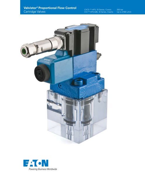
Valvistor ® <strong>Proportional</strong> <strong>Flow</strong> <strong>Control</strong><br />
Cartridge Valves<br />
CVCS-**-HFV, 10 Series, Covers<br />
CVI-**-HFV-A/B, 10 Series, Inserts<br />
350 bar<br />
Up to 2160 L/min
Table of Contents<br />
General Description ........................................................................................................................................................................ 2<br />
Valvistor Technology ........................................................................................................................................................................ 2<br />
Basic characteristics ....................................................................................................................................................................... 2<br />
Features and Benefits ..................................................................................................................................................................... 3<br />
Functional Symbols ......................................................................................................................................................................... 4<br />
Model Codes .................................................................................................................................................................................. 5<br />
Operating Data ............................................................................................................................................................................... 6<br />
Pivot Valve Electrical Data ............................................................................................................................................................... 6<br />
<strong>Flow</strong> Pressure Drop Charts............................................................................................................................................................. 7<br />
Pressure Drop ................................................................................................................................................................................. 9<br />
Hydraulic Fluids .............................................................................................................................................................................10<br />
Filtration Requirements .................................................................................................................................................................10<br />
Temperature Limits ........................................................................................................................................................................10<br />
Mounting Bolts and Assembly Torques .........................................................................................................................................11<br />
Seal Kits .........................................................................................................................................................................................11<br />
Ordering Procedure .......................................................................................................................................................................11<br />
Installation Dimensions .................................................................................................................................................................12<br />
Valvistor Line Extension (High performance and OBE options) .....................................................................................................13<br />
Released Part Numbers .................................................................................................................................................................14<br />
1 EATON Valvistor Cartridge Valve V-VLPO-MC011-E April 2009
1<br />
3<br />
Inlet A<br />
6<br />
7<br />
General Description<br />
<strong>Eaton</strong>’s Vickers ® HFV (Hydraulic Feedback Valvistor ® ) range of<br />
slip-in cartridge valves uses a self-regulating hydraulic design<br />
for the control of flow rate by a current-controlled PWM signal.<br />
The design achieves servo-type control of the main poppet<br />
without using an electrical feedback transducer.<br />
The construction and features of these valves open up a wide<br />
range of applications with hydraulic cylinders and motors.<br />
Such applications include ie casting, deep drawn presses,<br />
injection molding, container handling, shovel loaders, forestry<br />
and dump trucks. With the addition of HFV valves to the<br />
established ISO 7368 (DIN 24342) cartridge valves, <strong>Eaton</strong> has<br />
further enhanced an already comprehensive range.<br />
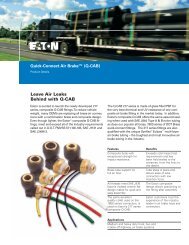
Valvistor Technology<br />
In “Valvistor” designs a main poppet amplifies a small flow<br />
through the pilot circuit, comparable to a transistor. Thus<br />
the name “Valvistor”, derived from “valve” and “transistor”.<br />
Figures 1 and 2 show the construction of proportional<br />
throttles to ISO 7368. In both cases a Vickers type KTG4V-3S<br />
proportional valve is used as the pilot control valve. Hydraulic<br />
position feedback is obtained by providing the main poppet<br />
with a longitudinal slot (5) in its cylindrical surface. This slot,<br />
together with a metering edge inside the sleeve, forms<br />
a variable orifice between the inlet of the valve and the volume<br />
above the main poppet (3). When the valve is closed<br />
and the main poppet is seated, the variable orifice area is<br />
almost closed.<br />
Figure 1<br />
Construction for flow direction A to B; poppet in the closed<br />
(no flow) condition. (Note: For flow A-B, poppet drilled from<br />
A.)<br />
Figure 2<br />
Construction for flow direction B to A; poppet partially open.<br />
(Note: For flow B-A, poppet drilled from B.)<br />
2<br />
Outlet B<br />
5<br />
4<br />
4<br />
2<br />
1<br />
Inlet A<br />
3<br />
3<br />
Outlet A<br />
6<br />
7<br />
6<br />
7<br />
2<br />
Outlet B<br />
1<br />
Inlet B<br />
4<br />
2<br />
3<br />
Outlet A<br />
6<br />
7<br />
Basic Characteristics<br />
Nominal Sizes:<br />
ISO 7368 DIN 24342<br />
06 NG16<br />
08 NG25<br />
09 NG32<br />
10 NG40<br />
11 NG50<br />
12 NG63<br />
Maximum operating pressure ......................350 bar (5000 psi)<br />
<strong>Flow</strong> ratings ............................. up to 2160 L/min (571 USgpm)<br />
Catalog data based on pilot valve KTG4V-3S-EN427.<br />
As the main poppet opens, the variable orifice area increases.<br />
The slot is a part of one leg of a hydraulic bridge circuit and<br />
provides an internal position feedback. With the pilot throttle<br />
valve closed (figure 1), there is no pilot flow through the<br />
closed-off slot in the seated poppet. The pressure above the<br />
main poppet (3) is equal to the pressure at the valve inlet (1),<br />
due to the controlled small opening at the variable orifice. As<br />
the upper area of the poppet is greater than the area facing<br />
the inlet (1), the poppet is held against its seat (6) by a force<br />
proportional to the difference between valve inlet and outlet<br />
pressures.<br />
Opening the pilot throttle valve (figure 2) lowers the pressure<br />
in volume (3) allowing the main poppet to move off its seat.<br />
As this occurs the slot passes the metering edge (7), opening<br />
the variable orifice and allowing flow through the pilot<br />
circuit. Initially the flow through the pilot valve equals the<br />
flow through the slot plus the volume displaced by the opening<br />
movement of the main poppet. The main poppet moves<br />
upwards until the pressure drops across the slot and the pilot<br />
effects a force balance on the poppet. The poppet is then<br />
held in a steady-state condition with equal flow across the<br />
slot and the pilot.<br />
If the flow through the pilot valve is reduced (by reducing the<br />
command current to the solenoid), the force balance of the<br />
main poppet is again disturbed and the main poppet moves<br />
downwards reducing the slot area and decreasing flow to the<br />
1<br />
upper chamber until the force balance is restored. Thus by<br />
Inlet B<br />
controlling flow through the pilot valve, the main poppet can<br />
be controlled in any position from fully closed to fully open. In<br />
this manner a very simple, effective servo-control of the main<br />
poppet is obtained. If the outlet pressure exceeds inlet pressure<br />
when the pilot valve is closed, the main poppet allows<br />
reverse flow (see CVCS model code). The main valve function<br />
is determined by the type of pilot fitted.<br />
If pressure compensation is added to the pilot stage, the<br />
complete valve is pressure compensated. If a pilot relief valve<br />
is fitted, the main stage operates as a relief valve. As the pilot<br />
flow is returned to the valve outlet (i.e. no “drain” connection)<br />
the valve is energy efficient. Therefore the position of<br />
the main poppet is controlled by a closed-loop system with<br />
a variable orifice in the poppet acting as the internal position<br />
feedback element. The command signal in this feedback system<br />
is pilot flow, as set at the proportional pilot throttle valve<br />
(4).<br />
EATON Valvistor Cartridge Valve V-VLPO-MC011-E April 2009 2
Features and Benefits<br />
The HFV range with its simplicity, cost effectiveness and performance<br />
level can be applied in almost all applications from<br />
high performance industrial areas such as injection molding<br />
to those applications just requiring proportional functionality.<br />
3 EATON Valvistor Cartridge Valve V-VLPO-MC011-E April 2009<br />
The data in this catalog is based on the specially developed<br />
proportional pilot KTG4V-3S-60-EN427. The functional flexibility<br />
of the Valvistor may be extended by the use of different<br />
pilots. Contact <strong>Eaton</strong> for application assistance.<br />
In addition, the HFV range offers:<br />
Unequalled simplicity No inner electrical feedback loop and associated electronics<br />
Two models: for flow direction A to B or B to A Provides system design options and flexibility<br />
Free flow in reverse direction Provides system design options and flexibility<br />
Poppet valve construction Provides tight shut-off and load holding<br />
Internal pilot flow Simple installation and energy efficient<br />
Very fast response Provides the system designer with high dynamic<br />
acceleration/velocity/deceleration profiles for demanding performance<br />
requirements such as:<br />
• Cylinder position control including lift/lower<br />
• Rotary actuator dynamic control<br />
• Velocity profile control<br />
Smooth closing and opening Shock-free start-up and shut-off allow high velocities to be maintained<br />
for longer periods, thus reducing cycle times<br />
Low hysteresis 8% to 1% depending on pilot valve used<br />
Integral feedback Internal hydraulic feedback provides effective, low-cost position control<br />
of main poppet<br />
Repeatability Provides repeatable and accurate actuator velocity to a given operator<br />
command input<br />
Electrical operation Current-controlled PWM signal<br />
Pressure compensation Can be achieved by pressure compensating pilot stage only<br />
Cost-effective design Provides multiple functions such as pressure compensation, flow control<br />
and reverse free flow check valve<br />
Optional manual override Pin design<br />
Compatible with antiwear hydraulic oils and phosphate esters (non alkyl) Flexible application for broad range of installations<br />
Electrical connections DIN or conduit box Provides design flexibility to meet OEM or user preference<br />
Inherent benefits of <strong>Eaton</strong> cartridge valve technology are applicable to the Valvistor range.
Functional Symbols<br />
<strong>Valvistor®</strong> <strong>Proportional</strong><br />
Throttle Valves<br />
Complete valve assembly comprises<br />
insert, cover and proportional solenoid<br />
operated pilot valve (pilot valve to be<br />
specified and ordered separately).<br />
Models without free reverse flow capability<br />
Use cover type CVCS-**-HFV*-W-<br />
*2(9)-1*<br />
Simplified symbol<br />
Models with free reverse flow capability<br />
Use cover type CVCS-**-HFV*-*2(9)-1*<br />
Note: Omit W from model code<br />
position 6<br />
Simplified symbol<br />
Direction of controlled flow<br />
A to B<br />
Use insert type CVI-**-HFV-20-A-***-1*<br />
P A B T<br />
Z 2<br />
X Y<br />
Z 1<br />
A<br />
P T<br />
A<br />
B<br />
B<br />
Z 2<br />
B<br />
P A B T<br />
Z 2<br />
Y<br />
X AP<br />
Y<br />
Y<br />
Z 1<br />
A<br />
B<br />
A<br />
AP1AP2 A<br />
A<br />
B<br />
P T<br />
Z 2<br />
B<br />
B to A<br />
Use insert type CVI-**-HFV-20-B-***-1*<br />
P A B T<br />
Z 2<br />
X Y<br />
Z 1<br />
A<br />
B<br />
P T<br />
EATON Valvistor Cartridge Valve V-VLPO-MC011-E April 2009 4<br />
A<br />
A<br />
B<br />
B<br />
Z 2<br />
P A B T<br />
Z 2<br />
Y<br />
Z 1<br />
A<br />
AP1AP2 A<br />
B<br />
P T<br />
X AP<br />
Y<br />
Y<br />
B<br />
A<br />
Z 2<br />
B
Model Codes <strong>Valvistor®</strong> <strong>Proportional</strong><br />
Throttle Valves<br />
1 Seal Material<br />
F3 - Seals for phosphate<br />
esters or chlorinated hydrocarbons.<br />
Omit for all other<br />
fluid types.<br />
2 Model<br />
CVI - Cartridge valve insert<br />
3 Nominal size to ISO<br />
7368 (DIN 24342)<br />
16 - 06 (NG16)<br />
25 - 08 (NG25)<br />
32 - 09 (NG32)<br />
40 - 10 (NG40)<br />
50 - 11 (NG50)<br />
63 - 12 (NG63)<br />
1 Fluid compatibility<br />
F3 - Seals for phosphate<br />
esters or chlorinated hydrocarbons.<br />
Omit for all other<br />
fluid types.<br />
2 Model<br />
CVI - Cartridge valve cover to<br />
ISO 7368<br />
3 Nominal size to ISO 7368<br />
(DIN 24342)<br />
16 - 06 (NG16)<br />
25 - 08 (NG25)<br />
32 - 09 (NG32)<br />
40 - 10 (NG40)<br />
50 - 11 (NG50)<br />
63 - 12 (NG63)<br />
5 EATON Valvistor Cartridge Valve V-VLPO-MC011-E April 2009<br />
(F3-) CVI - ** - HFV - 20 - * - *** - 1*<br />
1<br />
2<br />
4 <strong>Flow</strong> direction<br />
HFV - Hydraulic feedback,<br />
Valvistor<br />
5 Area ratio<br />
20 - 1:2 area ratio<br />
6 <strong>Flow</strong> direction<br />
A - For flow A to B<br />
B - For flow B to A<br />
3 4 5 6<br />
Valvistor Throttle Covers (Suitable for flows A to B and B to A)<br />
Pilot Valve<br />
For operation with 12V control system:<br />
KTG4V-3S2B 08N-(V)M-*** ***<br />
*(1)G5-60-EN427<br />
7 8<br />
(F3-) CVCS - ** - HFV - * - * - * 2 (9) - 1*<br />
1 2 3 4 5 6 7 8 9<br />
4 Type<br />
HFV - Hydraulic feedback,<br />
Valvistor<br />
5 Size 3 pilot valve mounting<br />
bolts<br />
1 - Imperial threads<br />
3 - Metric threads<br />
6 <strong>Control</strong> option<br />
W - Mainstage Valvistor without<br />
free reverse flow.<br />
Omit for standard mainstage<br />
Valvistor with free reverse<br />
flow capability<br />
7 <strong>Flow</strong> capacity at Δp = 10 bar (145 psi)<br />
Size/<strong>Flow</strong> Direction Code L/min USgpm<br />
16A 21 210 55<br />
16B 21 210 55<br />
25A 40 405 107<br />
25B 32 320 107<br />
32A 63 630 166<br />
32B 63 630 166<br />
40A 90 900 238<br />
40B 81 900 238<br />
50A 130 1305 345<br />
50B 130 1305 345<br />
63A 216 2160 571<br />
63B 216 2160 571<br />
10<br />
7 Thread/seal combination<br />
B - G (BSPF) threads for<br />
gage ports; metric<br />
threads for orifices (only<br />
available when ‘‘3’’ specified<br />
at position 5 )<br />
S - SAE O-ring gage; inch<br />
threads for orifices (only<br />
available when ‘‘1’’ specified<br />
at position 5 )<br />
For operation with 24V control system:<br />
KTG4V-3S2B 08N-(V)M-*** ***<br />
*(1)H5-60-EN427<br />
8 Seals<br />
2 - Inch O-ring seals to ISO<br />
3601<br />
9 Mounting bolts<br />
Sizes 16-40 only<br />
9 - Metric mounting bolts<br />
supplied as standard when<br />
‘‘B’’ (BSPF threads) specified<br />
at position 7 Omit for sizes<br />
50 and 63<br />
10 Design number, 1*<br />
series<br />
Subject to change. Installation<br />
dimensions unaltered for<br />
design numbers 10 to 19.<br />
For full technical details of this valve<br />
including types of electrical connections,<br />
see <strong>Eaton</strong>’s Vickers Slip-in Cartridge<br />
Valve Catalog.
Operating Data<br />
Data is typical with fluid at 36 cSt (168 SUS) and 50C (122F).<br />
Maximum pressure 350 bar (5000 psi)<br />
<strong>Flow</strong> ratings See model code (CVI)<br />
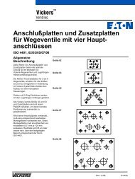
<strong>Control</strong>led flow characteristics See graphs on pages 7 and 8<br />
Pressure drop, free return flow See graphs on page 9<br />
Dynamic performance: 06 08 09 10 11 12<br />
Step input ▲ response at Δp = 10 bar (145 psi) (NG16) (NG25) (NG32) (NG40) (NG50) (NG63)<br />
Opening time (ms) 50 85 130 240 280 340<br />
Closing time (ms) 40 60 85 130 200 300<br />
Hysteresis ▲
<strong>Flow</strong>/Pressure Drop vs Solenoid Current<br />
(% of max.)<br />
<strong>Flow</strong>/Pressure Drop vs Solenoid Current (% of max.) 2.<br />
Size 16<br />
Size 25<br />
Size 32<br />
<strong>Flow</strong> rate<br />
<strong>Flow</strong> rate<br />
<strong>Flow</strong> rate<br />
USgpm<br />
70<br />
60<br />
50<br />
40<br />
30<br />
20<br />
10<br />
0<br />
L/min<br />
250<br />
200<br />
150<br />
100<br />
50<br />
USgpm L/min<br />
140<br />
120<br />
100<br />
80<br />
60<br />
40<br />
20<br />
0<br />
500<br />
400<br />
300<br />
200<br />
100<br />
0<br />
0<br />
0<br />
USgpm L/min<br />
200<br />
150<br />
100<br />
50<br />
0<br />
800<br />
700<br />
600<br />
500<br />
400<br />
300<br />
200<br />
100<br />
0<br />
100%<br />
75%<br />
<strong>Flow</strong> A<br />
0 10<br />
00<br />
2000 3000 4000<br />
10<br />
0%<br />
0<br />
0<br />
100%<br />
7 EATON Valvistor Cartridge Valve V-VLPO-MC011-E April 2009<br />
B<br />
50 100 150 200 250 300<br />
75%<br />
75%<br />
Pressure drop<br />
50 100 150 200 250 300<br />
0 10<br />
00<br />
2000 3000 4000<br />
Pressure drop<br />
50 100 150 200 250 300<br />
0 10<br />
00<br />
2000 3000 4000<br />
Pressure drop<br />
50%<br />
44%<br />
38%<br />
32%<br />
50<br />
00<br />
50%<br />
44%<br />
38%<br />
32%<br />
50<br />
00<br />
63%<br />
50%<br />
38%<br />
50<br />
00<br />
<strong>Flow</strong> rate<br />
USgpm L/min<br />
140<br />
120<br />
100<br />
80<br />
60<br />
40<br />
20<br />
0<br />
500<br />
400<br />
300<br />
200<br />
100<br />
0<br />
0<br />
F low<br />
B<br />
0 0<br />
bar 0 50 100 150 200 250 300<br />
bar<br />
psi<br />
bar<br />
psi<br />
bar<br />
psi<br />
<strong>Flow</strong> rate<br />
<strong>Flow</strong> rate<br />
USgpm<br />
70<br />
60<br />
50<br />
40<br />
30<br />
20<br />
10<br />
L/min<br />
250<br />
200<br />
150<br />
100<br />
50<br />
USgpm L/min<br />
200<br />
150<br />
100<br />
50<br />
0<br />
800<br />
700<br />
600<br />
500<br />
400<br />
300<br />
200<br />
100<br />
0<br />
100%<br />
10<br />
0%<br />
50 100 150 200 250 300<br />
0 1<br />
0<br />
0<br />
0<br />
2000<br />
3000<br />
4000<br />
100%<br />
50%<br />
0 10<br />
00<br />
2000 3000 4000<br />
0<br />
75%<br />
A<br />
Pressure drop<br />
Pressure drop<br />
75%<br />
50 100 150 200 250 300<br />
0 10<br />
00<br />
2000 3000 4000<br />
Pressure drop<br />
44%<br />
38%<br />
50<br />
00<br />
44%<br />
38%<br />
5<br />
0<br />
0<br />
0<br />
63%<br />
50%<br />
38%<br />
50<br />
00<br />
psi<br />
bar<br />
psi<br />
bar<br />
psi
<strong>Flow</strong>/Pressure Drop vs Solenoid Current<br />
(% of max.)<br />
Size 40<br />
Size 50<br />
Size 63<br />
<strong>Flow</strong> rate<br />
<strong>Flow</strong> rate<br />
<strong>Flow</strong> rate<br />
USgpm L/min<br />
400<br />
300<br />
200<br />
100<br />
0<br />
1500<br />
1250<br />
1000<br />
750<br />
500<br />
250<br />
USgpm L/min<br />
500<br />
400<br />
300<br />
200<br />
100<br />
0<br />
2000<br />
1750<br />
1500<br />
1000<br />
500<br />
USgpm L/min<br />
700<br />
600<br />
500<br />
400<br />
300<br />
200<br />
100<br />
0<br />
1250<br />
750<br />
250<br />
2500<br />
2000<br />
1500<br />
1000<br />
500<br />
0<br />
0<br />
<strong>Flow</strong> A B <strong>Flow</strong> B A<br />
50 100 150 200 250 300<br />
0 1 0 0 0 2000 3000 4000<br />
0<br />
0<br />
Pressure drop<br />
50 100 150 200 250 300<br />
0 1 0 0 0 2000 3000 4000<br />
0<br />
0<br />
100%<br />
94% 82%<br />
100% 88%<br />
100% 82%<br />
Pressure drop<br />
50 100 150 200 250 300<br />
0 1 0 0 0 2000 3000 4000<br />
Pressure drop<br />
75%<br />
69%<br />
57%<br />
0 0<br />
bar 0 50 100 150 200 250 300 bar<br />
5 0 0 0<br />
75%<br />
63%<br />
50%<br />
38%<br />
bar<br />
5 0 0 0<br />
75%<br />
69%<br />
63%<br />
50%<br />
bar<br />
5 0 0 0<br />
psi<br />
psi<br />
psi<br />
<strong>Flow</strong> rate<br />
<strong>Flow</strong> rate<br />
<strong>Flow</strong> rate<br />
USgpm L/min<br />
400<br />
300<br />
200<br />
100<br />
200<br />
1500<br />
1250<br />
1000<br />
750<br />
500<br />
250<br />
USgpm L/min<br />
500<br />
400<br />
300<br />
100<br />
USgpm<br />
700<br />
600<br />
500<br />
400<br />
300<br />
200<br />
100<br />
0<br />
0<br />
2000<br />
1750<br />
1500<br />
1250<br />
1000<br />
750<br />
500<br />
250<br />
L/min<br />
2500<br />
2000<br />
1500<br />
1000<br />
500<br />
0<br />
0<br />
0 1 0 0 0 2000 3000 4000<br />
Pressure drop<br />
50 100 150 200 250 300<br />
0 1 0 0 0 2000 3000 4000<br />
0<br />
0<br />
100%<br />
100% 94%<br />
100% 88%<br />
Pressure drop<br />
88%<br />
50 100 150 200 250 300<br />
0 1 0 0 0 2000 3000 4000<br />
Pressure drop<br />
82%<br />
75%<br />
63%<br />
57%<br />
5 0 0 0<br />
75%<br />
63%<br />
50%<br />
38%<br />
5 0 0 0<br />
82%<br />
75%<br />
69%<br />
57%<br />
50%<br />
EATON Valvistor Cartridge Valve V-VLPO-MC011-E April 2009 8<br />
bar<br />
bar<br />
5 0 0 0<br />
psi<br />
psi<br />
psi
Pressure Drops - Free Return <strong>Flow</strong><br />
Size 16<br />
Pressure drop<br />
Size 32<br />
Size 50<br />
psi bar<br />
80<br />
70<br />
60<br />
50<br />
40<br />
30<br />
20<br />
10<br />
6<br />
5<br />
4<br />
3<br />
2<br />
1<br />
0 0<br />
Pressure drop<br />
Pressure drop<br />
0 50 100 150 200<br />
0 10 20 30 40 50<br />
psi bar<br />
140 10<br />
9<br />
120<br />
8<br />
100 7<br />
80<br />
6<br />
5<br />
60 4<br />
40<br />
3<br />
2<br />
20<br />
1<br />
0 0<br />
psi bar<br />
<strong>Flow</strong> rate<br />
0 100 200 300 400<br />
500 600 700 800<br />
0 50 100 150 200 250<br />
<strong>Flow</strong> rate<br />
140<br />
10<br />
9<br />
120<br />
8<br />
100 7<br />
80<br />
6<br />
5<br />
60 4<br />
40<br />
3<br />
2<br />
20<br />
1<br />
0 0<br />
0 500 1000 1500<br />
0 100 200<br />
<strong>Flow</strong> rate<br />
300 400<br />
9 EATON Valvistor Cartridge Valve V-VLPO-MC011-E April 2009<br />
L/min<br />
USgpm<br />
L/min<br />
USgpm<br />
L/min<br />
USgpm<br />
Size 25<br />
Size 40<br />
Size 63<br />
Pressure drop<br />
Pressure drop<br />
Pressure drop<br />
psi bar<br />
140 10<br />
9<br />
120<br />
8<br />
100 7<br />
80<br />
6<br />
5<br />
60 4<br />
40<br />
3<br />
2<br />
20<br />
1<br />
0 0<br />
0 100 200 300 400<br />
psi bar<br />
140 10<br />
9<br />
120<br />
8<br />
100 7<br />
80<br />
6<br />
5<br />
60 4<br />
40<br />
3<br />
2<br />
20<br />
1<br />
0 0<br />
psi bar<br />
140<br />
10<br />
9<br />
120 8<br />
100 7<br />
80<br />
6<br />
5<br />
60 4<br />
40 3<br />
2<br />
20<br />
1<br />
0 0<br />
0 20 40 60 80100 120<br />
<strong>Flow</strong> rate<br />
0 250 500 750 1000<br />
0 50100 150<br />
<strong>Flow</strong> rate<br />
200 250<br />
0 500 1000 1500 2000<br />
0 100 200 300 400 500 600<br />
<strong>Flow</strong> rate<br />
450<br />
2500<br />
L/min<br />
USgpm<br />
L/min<br />
USgpm<br />
L/min<br />
USgpm
Hydraulic Fluids<br />
All cartridge valves can be used with antiwear hydraulic oils,<br />
and certain low viscosity fluids. Add prefix “F3” to model<br />
designations when phosphate esters (not alkyl-based) or chlorinated<br />
hydrocarbons are to be used. The extreme viscosity<br />
range is from 500 to 5 cSt (2270 to 42 SUS) but the recommended<br />
running range is from 54 to 13 cSt (245 to 70 SUS).<br />
Filtration Requirements<br />
Essential information on the correct methods for treating<br />
hydraulic fluid is included in the <strong>Eaton</strong>’s Vickers publication<br />
561 “Vickers Guide to Systemic Contamination <strong>Control</strong>”, available<br />
from your local <strong>Eaton</strong> distributor.<br />
Recommendations on filtration and the selection of products<br />
to control fluid condition are also included in <strong>Eaton</strong>’s Vickers<br />
publication 561.<br />
Recommended Fluid Cleanliness Level (ISO Code)<br />
Temperature Limits<br />
Ambient min ............................................................– 20C (–4F)<br />
Ambient max .......................................................+70C (+158F)<br />
Fluid temperatures<br />
Petroleum oil Wateroil containing<br />
Min. –20C +10C<br />
(–4F) (+50F)<br />
Max. +80C +54C<br />
(+176F) (+130F)<br />
Recommended cleanliness levels using petroleum oil under<br />
common conditions is based on the highest fluid pressure<br />
levels in the system. In referencing the table below, the bolded<br />
numbers highlight the recommended cleanliness level for<br />
Valvistor proportional throttles.<br />
Fluids other than petroleum, severe service cycles or temperature<br />
extremes are cause for adjustment of these cleanliness<br />
codes. See <strong>Eaton</strong>’s Vickers publication 561 for exact details.<br />
System Pressure Level System Pressure Level System Pressure Level<br />
Product 69 bar (1000 psi) 138 bar (2000 psi) 210+ bar (3000 psi)<br />
Vane Pumps – Fixed 20/18/15 19/17/14 18/16/13<br />
Vane Pumps – Variable 18/16/14 17/15/13<br />
Piston Pumps – Fixed 19/17/15 18/16/14 17/15/13<br />
Piston Pumps – Variable 18/16/14 17/15/13 16/14/12<br />
Directional Valves 20/18/15 20/18/15 19/17/14<br />
Pressure/<strong>Flow</strong> <strong>Control</strong> Valves 19/17/14 19/17/14 19/17/14<br />
Servo Valves 16/14/11 16/14/11 16/13/10<br />
<strong>Proportional</strong> Valves 17/15/12 17/15/12 15/13/11<br />
Cylinders 20/18/15 20/18/15 20/18/15<br />
Vane Motors 20/18/15 19/17/14 18/16/13<br />
Axial Piston Pumps 19/17/14 18/16/13 17/15/12<br />
Radial Piston Pumps 20/18/14 19/17/13 18/16/13<br />
EATON Valvistor Cartridge Valve V-VLPO-MC011-E April 2009 10
Mounting Bolts and Assembly Torques<br />
As noted in CVCS model code position , cover types CVCS-<br />
**-HFV1-(W)-B29-1*, sizes 16 to 40 inclusive, are supplied<br />
Inch threads<br />
Seal Kits<br />
For CVI-**-HFV inserts<br />
Nominal Seal Kit Type, See<br />
Size Model Code Standard F3-<br />
16 456173 02-157617<br />
25 456926 02-157618<br />
32 479449 02-157619<br />
40 478732 514808<br />
50 478733 02-157620<br />
63 456798 02-157621<br />
For CVCS-**-HFV covers<br />
Nominal Seal Kit Type, See<br />
Size Model Code Standard F3-<br />
16 02-157672 02-157671<br />
25 02-157674 02-157673<br />
32 02-157905 02-157906<br />
40 02-157712 02-157713<br />
50 02-310971 02-310973<br />
63 02-310975 02-310976<br />
Weights<br />
Nominal CVI-**-HFV CVCS-**-HFV<br />
Size Insert Cover<br />
16 0,13 kg (0.29lb) 1,2 kg (2.6 lb) 1,2 (2.6)<br />
25 0,33 (0.73) 1,9 (4.2)<br />
32 0,9 (1.98) 3,3 (7.3)<br />
40 1,35 (3.0) 6,3 (13.9)<br />
50 2,2 (4.8) 9,6 (21.0)<br />
63 5,4 (11.9) 19,4 (42.7)<br />
11 EATON Valvistor Cartridge Valve V-VLPO-MC011-E April 2009<br />
complete with metric mounting bolts. For correct installation<br />
of all other CVCS-**-HFV* cover types, the following <strong>Eaton</strong><br />
bolt kits are recommended.<br />
Nominal Size Bolt Size Bolt Kit Model Code Recommended Assembly Torque, lbf ft■<br />
16 5/16”-18 x 1.50 BKDNG16-700 26<br />
25 1/2”-13 x 1.50 BKDPNG25-704 81<br />
32 5/8”-11 x 2.00 BKDNG32-713 210<br />
40 3/4”-10 x 2.25 BKDPNG40-706 370<br />
50 3/4”-10 x 3.00 BKDNG50-708 429<br />
63 1 1/4”-7 x 3.50 BKDNG63-710 888<br />
Metric threads<br />
Nominal Size Bolt Size Bolt Kit Model Code Recommended Assembly Torque, Nms<br />
16 ♦ – 35<br />
25 ♦ – 110<br />
32 ♦ – 285<br />
40 ♦ – 500<br />
50 M20 x 80 BKDNG50-709M 580<br />
63 M30 x 90 BKDNG63-711M 1200<br />
■ With threads lubricated. ♦ See installation drawing, next page. For Pilot Valve<br />
See Slip-in Cartridge Valve Catalog.<br />
Ordering Procedure<br />
The component parts of the Valvistor proportional throttle<br />
assembly, including the pilot control valve, must be ordered<br />
individually. In addition there is a choice of electronics: typically<br />
a Vickers Eurocard drive amplifier, alternatively a Vickers<br />
12V DC or 24V DC proportional power plug. The full model<br />
code must be specified in all cases.<br />
Typical Valvistor Component Selection<br />
1 x CVI-**-HFV-20-*-**-10 insert, see this catalog<br />
1 x CVCS-**-HFV**-*2*-10 cover, see this catalog<br />
1 x cover mounting bolt kit u, see this catalog<br />
1 x KTG4V-3S- - - 60-EN427, see product catalog Slip-in<br />
Cartridge.<br />
1 x pilot valve mounting bolt kit, product catalog Valve<br />
Catalog.<br />
Plus:<br />
Drive Electronics for 24V DC System<br />
1 x EEA-PAM-523-A-32 Eurocard amplifier, see catalog 2464<br />
or<br />
1 x EHH-AMP-702-*-10 proportional power plug, see catalog<br />
2115<br />
Drive Electronics for 12V DC System<br />
1 x EHH-AMP-712-*-10 proportional power plug, catalog 2282
Installation Dimensions in mm (inches)<br />
CVCS-**-HFV*<br />
Port Y<br />
Profile of<br />
size 16 only<br />
Datum bolt hole for<br />
size 03 mounting face<br />
G min. for removal<br />
of cover assembly<br />
C<br />
C<br />
89,6 (3.53)<br />
B<br />
Port Z 1<br />
J<br />
Port Z2 A E<br />
T<br />
P<br />
(CVCS-**-HFV*-W only)<br />
Port X<br />
A D<br />
Location pin<br />
4 holes thru Ø K<br />
Metric mounting bolts, M<br />
supplied with sizes 16-40 only<br />
when -B29- specified<br />
at model code positions 5 and 6<br />
H<br />
G<br />
S<br />
3rd angle<br />
projection<br />
Valve A sq. B C max. D E max. G H J Ø K M S<br />
Size (K dia.) Mounting Bolts (supplied)<br />
16 66,0 85,5 4,5 68,5 14,5 8,0 36,0 32,50 8,75/9,25 M8 x 50 cap hd. screw 48,0<br />
(2.6) (3.36) (0.18) (2.7) (0.57) (0.32) (1.42) (1.28) (0.344/0.364) (1.89)<br />
25 86,0 – 3,5 88,5 13,5 10,5 25,0 20,75 13,75/14,25 M12 x 40 cap hd. screw 39,0<br />
(3.38) (0.14) (3.5) (0.53) (0.42) (0.98) (0.82) (0.541/0.561) (1.54)<br />
32 102,5 – 3,5 104,5 13,5 13,0 30,0 21,50 17,75/18,25 M16 x 55 cap hd. screw 48,0<br />
(4.0) (0.14) (4.2) (0.53) (0.52) (1.18) (0.85) (0.699/0.718) (1.89)<br />
40 126,0 – 2,0 128,5 11,0 15,0 35,0 21,50 21,75/22,25 M20 x 60 cap hd. screw 58,0<br />
(5.0) (0.08) (5.1) (0.43) (0.59) (1.38) (0.85) (0.856/0.875) (2.28)<br />
50 142,5 – 4,5 145,0 0 18,0 42,0 21,50 21,75/22,25 – 68,0<br />
(5.6) (0.18) (5.7) (0) (0.71) (1.66) (0.85) (0.856/0.875) (2.68)<br />
63 183,0 – 4,5 185,5 0 20,0 48,0 21,50 32,75/33,25 – 83,0<br />
(7.2) (0.18) (7.3) (0) (0.79) (1.89) (0.85) (1.289/1.309) (3.27)<br />
EATON Valvistor Cartridge Valve V-VLPO-MC011-E April 2009 12
<strong>Valvistor®</strong> Line Extension<br />
<strong>Proportional</strong> Slip-in Cartridge Valve, <strong>Flow</strong> <strong>Control</strong><br />
K(B)TG4V-3 Pilot Stage K(B)FTG4V-3 Pilot Stage<br />
<strong>Eaton</strong>’s Vickers ® line is now extended with the addition of K(B)<br />
TG4V-3 and K(B)FTG4V-3 pilot stage proportional valves. The<br />
new features and benefits of the higher performance and onboard<br />
electronics (OBE) open up new applications and markets.<br />
The valves piloted with K(B)FTG4V-3 offer performance<br />
that is close to conventional feedback valves. As its name<br />
implies, the Valvistor design has a main poppet valve that<br />
amplifies a low flow rate through the pilot circuit, similar to a<br />
transistor. This innovative design achieves servo-type control<br />
of the main poppet, without using an electrical main poppet<br />
position feedback transducer on the Slip-in cartridge valve.<br />
Features and benefits of the new valves include:<br />
• Integral hydraulic feedback on main stage — Closed loop,<br />
main-stage performance is achieved without using a mainstage<br />
LVDT.<br />
• Pilot stage selected to meet specific requirements — Costeffective<br />
design results in design flexibility.<br />
• Pilot flow is directed to the load — Higher flow efficiency is<br />
achieved since the flow is not wasted to the tank.<br />
• IP65 and IP67 environmental protection rated best in class<br />
— More reliable performance in harsh environments.<br />
• On board ramp adjustment on KBTG pilot.<br />
Applications include injection and blow molding, rubber molding,<br />
press, die-casting, offshore, civil engineering, marine, primary<br />
metal, and mobile applications. The tables below show<br />
existing Valvistor configurations and the new extended configurations<br />
with K(B) TG4V-3 and K(B)FTG4V-3 as pilot valves.<br />
High Performance<br />
13 EATON Valvistor Cartridge Valve V-VLPO-MC011-E April 2009<br />
Extended Configuration Extended Configurations<br />
Pilot Valve Non-OBE Valve OBE Valve<br />
Model Code & Part Number KFTG4V-3-2B13N-Z-M-U-H7-10, 506834 KBFTG4V-3-2B13N-Z-M1-PE7-H7-11, 5996165-001<br />
KBFTG4V-3-2B13N-Z-M2-PE7-H7-11, 5996350-001<br />
Step Response (ms) Open Close Open Close<br />
Delta P Tested 10 bar 10bar 10bar 10bar<br />
NG16 51 33 35 25<br />
NG25 88 50 50 30<br />
NG32 135 71 70 45<br />
NG40 249 108 130 65<br />
NG50 290 167 170 100<br />
NG63 352 250 200 150<br />
Hysteresis 1% 1% 1% 1%<br />
Notes Valvistor full flow reached at around 70% command input of K(B)F with 13N spool. For M2 version, the command input range<br />
is 4-12ma, valve is fully open at 4ma, and fully closed at 12ma.
Standard Performance<br />
Extended Configuration Extended Configurations<br />
Pilot Valve Non-OBE Valve OBE Valve<br />
Model Code & Part Number KTG4V-3-2B08N-M-U-H7-60-EN427, 02-398752 KBTG4V-3-2B08N-M1-PE7-H7-10-EN427, 02-398750<br />
Other configurations available.<br />
Contact <strong>Eaton</strong><br />
KBTG4V-3-2B08N-M2-PE7-H7-10-EN427, 02-398751<br />
Step Response (ms) Open Close Open Close<br />
Delta P Tested 10 bar 10 bar 10 bar 10 bar<br />
NG16 50 40 38 24<br />
NG25 85 60 66 36<br />
NG32 130 85 101 51<br />
NG40 240 130 186 78<br />
NG50 280 200 217 120<br />
NG63 340 300 264 180<br />
Hysteresis
<strong>Eaton</strong><br />
Hydraulics Group USA<br />
14615 Lone Oak Road<br />
Eden Prairie, MN 55344<br />
USA<br />
Tel: 952-937-9800<br />
Fax: 952-294-7722<br />
www.eaton.com/hydraulics<br />
© 2009 <strong>Eaton</strong> <strong>Corporation</strong><br />
All rights reserved<br />
Printed in USA<br />
Document No. V-VLPO-MC011-E<br />
April 2009<br />
<strong>Eaton</strong><br />
Hydraulics Group Europe<br />
Route de la Longeraie 7<br />
1110 Morges<br />
Switzerland<br />
Tel: +41 (0) 21 811 4600<br />
Fax: +41 (0) 21 811 4601<br />
<strong>Eaton</strong><br />
Hydraulic Group Asia Pacific<br />
11th Floor Hong Kong New World Tower<br />
300 Huaihai Zhong Road<br />
Shanghai 200021<br />
China<br />
Tel: 86-21-6387-9988<br />
Fax: 86-21-6335-3912