Pressure Reducing Automatic Metering Valve (AMV) - Bermad
Pressure Reducing Automatic Metering Valve (AMV) - Bermad
Pressure Reducing Automatic Metering Valve (AMV) - Bermad

Create successful ePaper yourself
Turn your PDF publications into a flip-book with our unique Google optimized e-Paper software.
BERMAD Irrigation<br />
<strong>Pressure</strong> <strong>Reducing</strong><br />
<strong>Automatic</strong> <strong>Metering</strong><br />
<strong>Valve</strong> (<strong>AMV</strong>)<br />
IR-920-D2-R<br />
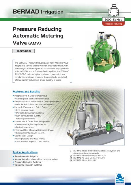
The BERMAD <strong>Pressure</strong> <strong>Reducing</strong> <strong>Automatic</strong> <strong>Metering</strong> <strong>Valve</strong><br />
integrates a vertical turbine Woltman-type water meter, with<br />
a diaphragm actuated hydraulic control valve. Equipped with<br />
a Shut-Off Pilot and a <strong>Pressure</strong> <strong>Reducing</strong> Pilot, the BERMAD<br />
IR-920-D2-R reduces higher upstream pressure to lower<br />
constant downstream pressure. It automatically shuts itself<br />
after accurately delivering a preset quantity of water.<br />
Features and Benefits<br />
■ Integrated "All-in-One" Control <strong>Valve</strong><br />
❏ Saves space, cost and maintenance<br />
■ Easy Modification to Mechanical Drive Hydrometer<br />
❏ Adaptable to future computerized systems<br />
■ Hydraulic <strong>Pressure</strong> and Batch Control<br />
❏ Line pressure driven<br />
❏ Protects downstream systems<br />
❏ Non-computerized quantity<br />
follow-up and control<br />
■ Internal Inlet & Outlet Flow Straighteners<br />
❏ Saves on straightening distances<br />
❏ Maintains accuracy<br />
■ Integrated Flow <strong>Metering</strong> Calibration Device<br />
❏ Measurement precision to ±2%<br />
■ User-Friendly Design<br />
❏ Easy pressure and dose setting<br />
❏ Simple in-line inspection and service<br />
Typical Applications<br />
■ Semi-<strong>Automatic</strong> Irrigation<br />
■ Manual Irrigation intended for computerization<br />
■ <strong>Pressure</strong> <strong>Reducing</strong> Systems<br />
■ Volumetric Irrigation Systems<br />
[4]<br />
900 Series<br />
<strong>Pressure</strong> <strong>Reducing</strong><br />
[1] BERMAD Model IR-920-D2-R protects the system and<br />
delivers precise water quantity.<br />
[2] BERMAD Relief <strong>Valve</strong> Model IR-43Q-R<br />
[3] BERMAD Air <strong>Valve</strong> Model ARC-A-P-I<br />
[4] BERMAD Model IR-310-B<br />
[3]<br />
[1]<br />
[2]
BERMAD Irrigation<br />
IR-920-D2-R<br />
For full technical details, refer to Engineering Section.<br />
Technical Specifications<br />
Dimensions and Weights<br />
Size DN<br />
Inch<br />
L<br />
H<br />
C<br />
R<br />
A; B<br />
Weight<br />
80<br />
3<br />
100<br />
4<br />
150<br />
6<br />
200<br />
8<br />
250<br />
10<br />
mm 300 350 500 600 600<br />
inch 11.8 13.8 19.7 23.6 23.6<br />
mm 405 470 625 640 640<br />
inch 15.9 18.5 24.6 25.2 25.2<br />
mm 290 340 450 465 465<br />
inch 11.4 13.4 17.7 18.3 18.3<br />
mm 123 137 216 228 228<br />
inch 4.8 5.4 8.5 9 9<br />
mm 305 325 390 390 415<br />
inch 12 12.8 15.4 15.4 16.3<br />
Kg 23 31 71 93 141<br />
Ib. 57.7 68.3 156.5 205 310.9<br />
Accuracy & Flow Data (ISO 4064-1, Class A)<br />
Size Accuracy DN<br />
inch<br />
Q min<br />
(Minimum flow)<br />
5%<br />
Qn, ISO 4064-1<br />
2%<br />
(Nominal flow)<br />
Qper=Q3<br />
(Permanent flow)<br />
Dial Options<br />
Capacity<br />
Graduation<br />
40<br />
80<br />
120<br />
150<br />
1<br />
1<br />
Technical Data<br />
Patterns and Sizes:<br />
Globe: 3-10”; DN80-250<br />
Angle 90º: 3-8”; DN80-200<br />
Angle 120º: 4”; DN100<br />
End Connections:<br />
Flanged: 3-10”; DN80-250<br />
<strong>Pressure</strong> Ratings: 16 bar; 232 psi<br />
Minimum Operating <strong>Pressure</strong>:<br />
0.5 bar; 7 psi<br />
For lower pressure requirements,<br />
consult factory<br />
Setting Range: 1-10 bar; 15-145 psi<br />
Setting ranges vary according to specific pilot<br />
spring. Please consult factory.<br />
How to Order<br />
2%<br />
2<br />
2<br />
Globe G<br />
Angle A<br />
120 (4”; DN100 only) H<br />
ISO-16 16<br />
ISO-10 10<br />
ISO-14 (ISO-10/4 Holes) 14<br />
ANSI-125 A1<br />
JIS-10 J1<br />
BST-D BD<br />
info@bermad.com • www.bermad.com<br />
�<br />
Materials:<br />
Body and Cover:<br />
Polyester Coated Cast or Ductile Iron<br />
Internals:<br />
St. St. & Glass Fiber Reinforced Nylon<br />
Impeller: Polypropylene<br />
Elastomers: Reinforced NR & NBR<br />
Pivots and Bearings: Tungsten Carbide<br />
Control Accessories: Brass<br />
Tubing and Fittings:<br />
Reinforced Plastic and Brass<br />
Plastic Tubing & Brass Fittings PB<br />
Copper Tubing & Brass Fittings CB<br />
Flow Chart<br />
The information herein is subject to change without notice. BERMAD shall not be held liable for<br />
any errors. All rights reserved. © Copyright by BERMAD.<br />
PC9AED2-20R 05<br />
�<br />
�<br />
�<br />
�<br />
�<br />
∆P<br />
psi<br />
12.5<br />
10.0<br />
7.5<br />
5.0<br />
2.5<br />
1.5<br />
1.0<br />
0.75<br />
0.5<br />
0.25<br />
0.15<br />
0.1<br />
0.08<br />
0.06<br />
0.05<br />
0.04<br />
0.03<br />
0.02<br />
0.015<br />
0.01<br />
Operation<br />
Please specify the requested valve in the following sequence: (for more options, refer to Ordering Guide.)<br />
Sector Size Primary<br />
Feature<br />
Control<br />
Categories<br />
Additional<br />
Feature<br />
3”<br />
DN80<br />
4”<br />
DN100<br />
[1]<br />
[3]<br />
12345<br />
900 Series<br />
<strong>Pressure</strong> <strong>Reducing</strong><br />
The <strong>Pressure</strong> <strong>Reducing</strong> Pilot [1] commands the <strong>AMV</strong> to<br />
throttle closed should Downstream <strong>Pressure</strong> [P2] rise above<br />
pilot setting, and modulate open when it drops below pilot<br />
setting. Upon delivering the preset quantity of water, the <strong>AMV</strong><br />
manually preset Control Head Mechanism [2] mechanically<br />
shifts the Shut-Off Pilot [3], which closes the Hydraulic Relay<br />
<strong>Valve</strong> [4]. This pressurizes the Control Chamber [5], causing<br />
the <strong>AMV</strong> to close.<br />
Pattern Construction End Coating Voltage &<br />
Materials Connections<br />
Position<br />
[2]<br />
[4]<br />
[5]<br />
[P2]<br />
6”<br />
DN150<br />
Flow<br />
m<br />
6 8 10 15 20 30 40 60 80 100 150 200 300 400 600<br />
3 /h<br />
Flow<br />
gpm 50<br />
25<br />
Tubing &<br />
Fittings<br />
40 m 3 040 6,000 m 3 6K0<br />
80 m 3 080 8,000 m 3 8K0<br />
120 m 3 120 13,000 Gal. 1G0<br />
150 m 3 150 50,000 Gal. 5G0<br />
200 m 3 200 130,000 Gal. 1KG<br />
350 m 3 350 200,000 Gal. 2KG<br />
600 m 3 600 510,000 Gal. 5KG<br />
800 m 3 800 875,000 Gal. 8KG<br />
1,200 m 3 1K0 1,300,000 Gal. 1MG<br />
2,100 m 3 2K0 2,100,000 Gal. 2MG<br />
3,500 m 3 3K0<br />
75<br />
100<br />
150<br />
200<br />
250<br />
300<br />
350<br />
400<br />
500<br />
Dial<br />
Capacity<br />
8 & 10”<br />
DN200 & 250<br />
750<br />
1000<br />
Pulse<br />
Rate<br />
1500<br />
2000<br />
2500<br />
Additonal<br />
Attributes<br />
IR 3-10" 920 D2 00 G I 16 PG - PB 800 NPS R<br />
Other sizes<br />
available on request.<br />
Cubic Meter (m 3 ) 1000 Gallon<br />
200<br />
350<br />
600<br />
800<br />
1,200<br />
2,100<br />
3,500<br />
6,000<br />
8,000<br />
13<br />
50<br />
130<br />
200<br />
500<br />
Cubic Meter (m 3 ) Gallon<br />
5<br />
10<br />
10<br />
10<br />
20<br />
50<br />
100<br />
100<br />
100<br />
100<br />
1000<br />
2,500<br />
5,000<br />
10,000<br />
870<br />
1,300<br />
2,000<br />
20,000<br />
25,000<br />
25,000<br />
3" ■ ■ ■ ■ ■ ■ ■ ■ ■ ■ ■ ■ ■ ■<br />
4" ■ ■ ■ ■ ■ ■ ■ ■ ■ ■ ■ ■ ■<br />
6" ■ ■ ■ ■ ■ ■ ■ ■ ■ ■<br />
8" & 10" ■ ■ ■ ■ ■ ■ ■ ■ ■ ■<br />
80<br />
3<br />
100<br />
4<br />
150<br />
6”<br />
200 & 250<br />
8 & 10<br />
m3 3.2 4.8 10 12<br />
gpm 14.1 21.1 44 52.8<br />
m3 40 60 150 250<br />
gpm 176 264 660 1100<br />
m3 100 160 250 400<br />
gpm 440 704 1100 1760<br />
∆P 2-Way Circuit "Added Head Loss",<br />
bar (for "V" below 2 m/s; 6.5 f/s): 0.3 bar; 4.5 psi<br />
1.0<br />
0.8<br />
0.6<br />
0.5<br />
0.4<br />
0.3<br />
0.2<br />
0.15<br />
Metal Control Accessories R<br />
Homologation Approved L<br />
Other attributes available on request