Simulink Tutorial on Digital Modulation Methods - Cengage Learning
Simulink Tutorial on Digital Modulation Methods - Cengage Learning
Simulink Tutorial on Digital Modulation Methods - Cengage Learning

Create successful ePaper yourself
Turn your PDF publications into a flip-book with our unique Google optimized e-Paper software.
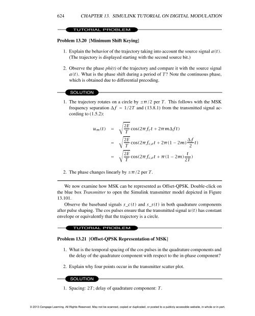
624 CHAPTER 13. SIMULINK TUTORIAL ON DIGITAL MODULATION<br />
TUTORIAL PROBLEM<br />
Problem 13.20 [Minimum Shift Keying]<br />
1. Explain the behavior of the trajectory taking into account the source signal a(t).<br />
(The trajectory is displayed starting with the sec<strong>on</strong>d source bit.)<br />
2. Observe the phase phi(t) of the trajectory and compare it with the source signal<br />
a(t). What is the phase shift during a period of T? Note the c<strong>on</strong>tinuous phase,<br />
which is obtained due to differential precoding.<br />
SOLUTION<br />
1. The trajectory rotates <strong>on</strong> a circle by ±π/2 per T. This follows with the MSK<br />
frequency separati<strong>on</strong> ∆f = 1/2T and (13.8.1) from the transmitted signal according<br />
to (1.5.2):<br />
um(t) =<br />
=<br />
�<br />
2E<br />
�<br />
2E<br />
T cos(2πfct + 2πm∆ft)<br />
2. The phase changes linearly by ±π/2 per T.<br />
=<br />
T cos(2πfc,ot + 2π(1 − 2m) ∆f<br />
2 t)<br />
�<br />
2E<br />
T cos(2πfc,ot + π(1 − 2m) t<br />
2T )<br />
We now examine how MSK can be represented as Offset-QPSK. Double-click <strong>on</strong><br />
the blue box Transmitter to open the <str<strong>on</strong>g>Simulink</str<strong>on</strong>g> transmitter model depicted in Figure<br />
13.101.<br />
Observe the baseband signals s_c(t) and s_s(t) in both quadrature comp<strong>on</strong>ents<br />
after pulse shaping. The cos pulses ensure that the transmitted signal u(t) has c<strong>on</strong>stant<br />
envelope or equivalently that the trajectory is a circle.<br />
TUTORIAL PROBLEM<br />
Problem 13.21 [Offset-QPSK Representati<strong>on</strong> of MSK]<br />
1. What is the temporal spacing of the cos pulses in the quadrature comp<strong>on</strong>ents and<br />
the delay of the quadrature comp<strong>on</strong>ent with respect to the in-phase comp<strong>on</strong>ent?<br />
2. Explain why four points occur in the transmitter scatter plot.<br />
SOLUTION<br />
1. Spacing: 2T; delay of quadrature comp<strong>on</strong>ent: T.<br />
© 2013 <strong>Cengage</strong> <strong>Learning</strong>. All Rights Reserved. May not be scanned, copied or duplicated, or posted to a publicly accessible website, in whole or in part.