Simulink Tutorial on Digital Modulation Methods - Cengage Learning
Simulink Tutorial on Digital Modulation Methods - Cengage Learning
Simulink Tutorial on Digital Modulation Methods - Cengage Learning

You also want an ePaper? Increase the reach of your titles
YUMPU automatically turns print PDFs into web optimized ePapers that Google loves.
616 CHAPTER 13. SIMULINK TUTORIAL ON DIGITAL MODULATION<br />
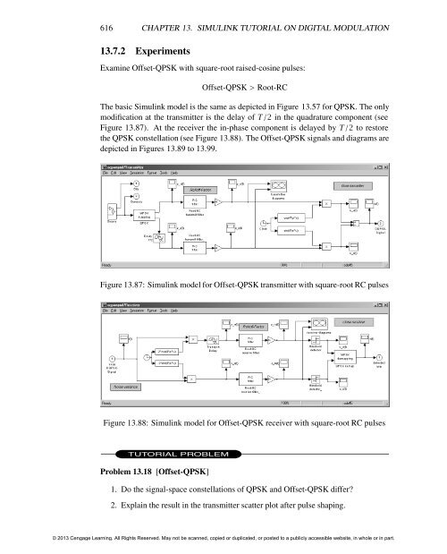
13.7.2 Experiments<br />
Examine Offset-QPSK with square-root raised-cosine pulses:<br />
Offset-QPSK > Root-RC<br />
The basic <str<strong>on</strong>g>Simulink</str<strong>on</strong>g> model is the same as depicted in Figure 13.57 for QPSK. The <strong>on</strong>ly<br />
modificati<strong>on</strong> at the transmitter is the delay of T/2 in the quadrature comp<strong>on</strong>ent (see<br />
Figure 13.87). At the receiver the in-phase comp<strong>on</strong>ent is delayed by T/2 to restore<br />
the QPSK c<strong>on</strong>stellati<strong>on</strong> (see Figure 13.88). The Offset-QPSK signals and diagrams are<br />
depicted in Figures 13.89 to 13.99.<br />
Figure 13.87: <str<strong>on</strong>g>Simulink</str<strong>on</strong>g> model for Offset-QPSK transmitter with square-root RC pulses<br />
Figure 13.88: <str<strong>on</strong>g>Simulink</str<strong>on</strong>g> model for Offset-QPSK receiver with square-root RC pulses<br />
TUTORIAL PROBLEM<br />
Problem 13.18 [Offset-QPSK]<br />
1. Do the signal-space c<strong>on</strong>stellati<strong>on</strong>s of QPSK and Offset-QPSK differ?<br />
2. Explain the result in the transmitter scatter plot after pulse shaping.<br />
© 2013 <strong>Cengage</strong> <strong>Learning</strong>. All Rights Reserved. May not be scanned, copied or duplicated, or posted to a publicly accessible website, in whole or in part.