Simulink Tutorial on Digital Modulation Methods - Cengage Learning
Simulink Tutorial on Digital Modulation Methods - Cengage Learning
Simulink Tutorial on Digital Modulation Methods - Cengage Learning

You also want an ePaper? Increase the reach of your titles
YUMPU automatically turns print PDFs into web optimized ePapers that Google loves.
13.6. QUADRATURE PHASE-SHIFT KEYING (QPSK) 613<br />
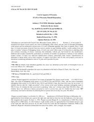
Figure 13.75: Cos carrier parameter window<br />
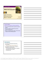
Figure 13.77: Receiver trajectory for<br />
QPSK with phase offset in cos comp<strong>on</strong>ent<br />
SOLUTION<br />
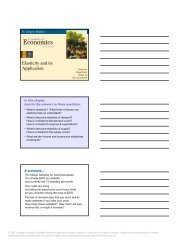
Figure 13.76: Sin carrier parameter window<br />
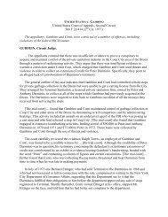
Figure 13.78: Receiver scatter plot for<br />
QPSK with phase offset in cos comp<strong>on</strong>ent<br />
At the sampling time <strong>on</strong>ly the correct values ±1 occur in the sin comp<strong>on</strong>ent. In the cos<br />
comp<strong>on</strong>ent we still observe four possible values. Therefore, the received signal-space<br />
c<strong>on</strong>stellati<strong>on</strong> is distorted.<br />
Frequency Offset<br />
In order to investigate a frequency offset, modify the demodulating carriers according<br />
to Figures 13.81 and 13.82. Figures 13.83 to 13.86 show the resulting signal-space<br />
diagrams and eye patterns.<br />
TUTORIAL PROBLEM<br />
Problem 13.17 [QPSK with Frequency Offset] Describe the eye patterns and signalspace<br />
plots. Is error-free detecti<strong>on</strong> possible?<br />
© 2013 <strong>Cengage</strong> <strong>Learning</strong>. All Rights Reserved. May not be scanned, copied or duplicated, or posted to a publicly accessible website, in whole or in part.