Quick Installation Manual CDP-66/99/133 - Matica MB doo
Quick Installation Manual CDP-66/99/133 - Matica MB doo
Quick Installation Manual CDP-66/99/133 - Matica MB doo

You also want an ePaper? Increase the reach of your titles
YUMPU automatically turns print PDFs into web optimized ePapers that Google loves.
Technical Hotline<br />
Tel +49 (0) 71 38/8 10 97-0 _ Fax -29<br />
Please retain for reference<br />
Customer number<br />
Company name<br />
Contact person<br />
Telephone number<br />
Equipment designation or serial number<br />
Fault description, "Critical Fault'' Number<br />
Safety information<br />
This quick installation manual does not replace the full operating instructions (Art. No:<br />
80-010-1500) and serve as a guide only!<br />
A good knowledge of using stud welding equipment and its components is necessary.<br />
Only persons over the age of 18 may carry out stud welding work.<br />
Before using the unit, all necessary protective measures must be taken and the safety<br />
information observed.<br />
Current directives and standards such as DIN EN ISO 14555, DVS Notices 0901 + 0903<br />
+ 0904 must also be observed.<br />
Stand 03/07<br />
Subject to technical changes without prior notice<br />
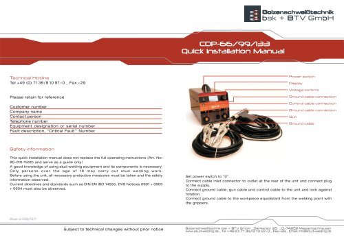
<strong>CDP</strong>-<strong>66</strong>/<strong>99</strong>/<strong>133</strong><br />
<strong>Quick</strong> <strong>Installation</strong> <strong>Manual</strong><br />
Power switch<br />
Display<br />
Voltage control<br />
Ground cable connection<br />
Control cable connection<br />
Ground cable connection<br />
Gun<br />
Ground cable<br />
Set power switch to "0".<br />
Connect cable inlet connector to outlet at the rear of the unit und connect plug<br />
to the supply.<br />
Connect ground cable, gun cable and control cable to the unit and lock against<br />
rotation.<br />
Connect ground cable to the workpiece equidistant from the welding point with<br />
the grippers.<br />
Bolzenschweißtechnik bsk + BTV GmbH _ Daimlerstr. 25 _ D-74252 Massenbachhausen<br />
www.stud-welding.de _ Tel +49 (0) 71 38/8 10 97- 0 _ Fax - 29 _ Email: info@stud-welding.de
Commissioning<br />
Stop screw<br />
Lock nut<br />
Stud collect<br />
Stud<br />
1-1,5mm<br />
Setting up stud collet<br />
// Select stud collet appropriate to welding<br />
element.<br />
// Adjust stud collet (see Fig.).<br />
// Insert stud collet in gun.<br />
// Tighten with supplied size 17 socket.<br />
Adjusting KP-B welding gun<br />
( contact )<br />
// Only the spring pressure can be adjusted on<br />
the contact gun.<br />
// Turn adjusting screw on gun using a coin to<br />
adjust the spring force to the welding task if<br />
necessary.<br />
// Turning the screw clockwise increases the<br />
spring force with a shorter welding time.<br />
// Turning the screw counter-clockwise increases<br />
the welding time.<br />
// Default setting about 20%; 1-2 scale divisions<br />
in lateral window.<br />
HPL-8 welding gun<br />
( gap or lift )<br />
// Place the gun on a flat surface and turn the<br />
setting control counter-clockwise until the pin<br />
including bolt are flat.<br />
// This setting is termed "zero lift".<br />
// Turn control in the opposite direction until the<br />
lift corresponds to the particular welding task.<br />
// Default setting for steel 1.5 - 2 mm (1.5 to 2<br />
rotations).<br />
// Default setting for aluminium 2.5 to 3.5mm<br />
Switching on the unit<br />
Set power switch to "I".<br />
After a short self-test, the main menu is<br />
automatically displayed.<br />
The charging voltage can be set with the<br />
voltage control.<br />
The charging voltage is shown enlarged<br />
within the bar graph.<br />
The stud diameter symbol serves for<br />
orientation.<br />
A tolerance range is available for all stud<br />
diameters.<br />
The Info menu can be displayed by<br />
pressing the control.<br />
>> Resettable piece counter (by pressing<br />
twice).<br />
>> Total piece counter<br />
>> Serial number
Hotline<br />
Tel +49 (0) 71 38/8 10 97-0 _ Fax -29<br />
Bitte halten Sie vorab bereit:<br />
Kundenummer<br />
Firmenname<br />
Kontaktperson<br />
Telefonnummer<br />
Gerätetypbezeichnung ggf. Seriennummer<br />
Fehlerbeschreibung, „Critical Error“ Nummer<br />
Sicherheitshinweise<br />
Diese Schnellinstallationsanleitung ersetzt nicht die ausführliche Bedienungsanleitung<br />
(Art.-Nr.: 80-010-1504). Sie dient nur zur Unterstützung!<br />
Es sind Kenntnisse im Umgang mit Bolzenschweißgeräten und deren Komponenten<br />
notwendig.<br />
Bolzenschweißarbeiten dürfen nur von Personen ausgeführt werden, die das<br />
18. Lebensjahr vollendet haben.<br />
Treffen Sie vor der Inbetriebnahme des Gerätes alle notwendigen Schutzmaßnahmen<br />
und beachten Sie unbedingt alle Sicherheitshinweise.<br />
Beachten Sie auch die aktuellen Regelwerke und Normungen, wie z.B. DIN EN ISO<br />
14555, DVS-Merkblätter 0902 + 0904.<br />
Stand 2010<br />
Technische Änderungen vorbehalten<br />
Drawn-Arc-Controller DA-800<br />
Schnellinstallationsanleitung<br />
Schalterstellung Netzschalter auf „0“<br />
Netzschalter CEE<br />
Grafik-Display<br />
Drehimpulsgeber<br />
Anschluss Massekabel<br />
Anschluss Steuerkabel<br />
Anschluss Pistolenkabel<br />
Pistole<br />
Massekabel<br />
32A CEE - Netzstecker an geeignete Steckdose anschließen (Sicherung 32A träge).<br />
Steuerleitung, Pistolen- und Massekabel am Gerät anschließen und durch Verdrehen<br />
sichern.<br />
Die zwei Grippzangen des Massekabels gleichmäßig weit von der Schweißstelle<br />
diagonal am Werkstück anbringen um magnetische Blaswirkung zu vermeiden.<br />
Bei Schutzgasanwendung:<br />
Gasanschluß an der Geräterückseite mit geeignetem Schlauch an Druckminderer<br />
einer Schutzgasflasche (82/18, Ar/CO2) anschließen und Durchflußmenge auf<br />
4-6 l/min einstellen. Achtung: Gasflasche gegen Umfallen sichern!<br />
Bolzenschweißtechnik bsk + BTV GmbH _ Daimlerstr. 25 _ D-74252 Massenbachhausen<br />
www.stud-welding.de _ Tel +49 (0) 71 38/8 10 97- 0 _ Fax - 29 _ Email: info@stud-welding.de
Pistole einrichten<br />
Anschlagschraube<br />
Kontermutter<br />
Bolzenhalter<br />
Bolzen<br />
1-1,5mm<br />
Pistole einrichten<br />
Achtung: Gas Gerät muß bei allen Einrichtarbeiten an den<br />
Pistolen ausgeschaltet sein oder zumindest die<br />
Masseverbindung getrennt werden.<br />
Bolzenschweißpistole KHP-10<br />
// Bolzenhalter zum Schweißelement passend wählen<br />
// Bolzenhalter einstellen (siehe Abbildung)<br />
// Bolzenhalter in Pistole einstecken<br />
// Mit beigefügtem Steckschlüssel SW17 fest anziehen<br />
>> Pistole ist nun einsatzbereit!<br />
Bolzenschweißpistole KHPL-12<br />
// Bolzenhalter zum Schweißelement entspr. wählen<br />
// Bolzenhalter auf Doppelnippel schrauben<br />
// Bolzenhalter mit Maulschlüssel SW14 festziehen<br />
(Achtung: Mit Maulschlüssel SW 17 am Doppelnippel kontern!)<br />
// Entsprechendes Stativ (Gas- oder Keramikringstativ) auf<br />
Pistole setzen und fixieren<br />
Keramikringstativ<br />
( entfällt bei Pistole KHP-10 )<br />
// Geeigneten Keramikringhalter in Fußplatte stecken und<br />
mit 2,5 mm Imbusschlüssel sichern<br />
// Bolzen bis zum Anschlag in den Bolzenhalter stecken<br />
// passenden Keramikring in Keramikringhalter stecken,<br />
dabei leicht drehen<br />
// Bolzenüberstand bzw. Eintauchmaß gem. Abb. einstellen<br />
(1,5 -5 mm je nach Bolzendurchmesser bzw. Form),<br />
indem das Stativ entsprechend verstellt und die Säulenklemmschrauben<br />
anschließend fest angezogen werden<br />
// Fußplatte an den Imbusschrauben ausrichten, so daß Bolzen<br />
und Keramikring zentriert sind und der Bolzen beim Anheben<br />
den Keramikring nicht berührt, ansonsten droht Eintauchbehinderung<br />
// Überstand und Leichtgängigkeit des Bewegungssystems<br />
durch manuelles Hineinschieben des Bolzens gegen die<br />
Feder in der Pistole überprüfen bzw. eingebaute<br />
Abhubtestfunktion nutzen, indem die Pistole in der Luft<br />
betätigt wird (Achtung: Es darf kein Werkstückkontakt<br />
vorhanden sein ggf. Massekabel entfernen)<br />
>> Pistole ist nun einsatzbereit!<br />
Schutzgasstativ<br />
( entfällt bei Pistole KHP-10 )<br />
// Bolzen in Gas-Bolzenhalter (115 mm lang) bis zum Anschlag<br />
einsetzen<br />
// Bolzenüberstand am Schutzgasstativ gem. Abb. einstellen<br />
// ggf. Fußplatte zentrieren<br />
// Stativ festschrauben<br />
// Überstand und Leichtgängigkeit des Bewegungssystems<br />
durch manuelles Hineinschieben des Bolzens gegen die<br />
Feder in der Pistole überprüfen bzw. eingebaute<br />
Abhubtestfunktion nutzen, indem die Pistole in der Luft<br />
betätigt wird (Achtung: Es darf kein Werkstückkontakt<br />
vorhanden sein ggf. Massekabel entfernen)<br />
>> Pistole ist nun einsatzbereit!<br />
Gerät einschalten<br />
// Netzschalter auf „I“<br />
// Nach kurzem Selbsttest automatische Umschaltung ins<br />
Hauptmenü<br />
// Mit dem Drehimpulsgeber können Sie die Schweißzeit in<br />
Millisekunden einstellen<br />
// Einstellbereich Kurzzeithubzündung: 5ms – <strong>99</strong>ms<br />
// Einstellbereich Hubzündung: 100ms – 500ms<br />
// Die Schweißzeit wird groß innerhalb des Bar-Graphen<br />
dargestellt<br />
// Das jeweilige Bolzendurchmessersymbol dient als<br />
Orientierungshilfe<br />
// Für jeden Bolzendurchmesser steht ein Toleranzbereich für<br />
die Schweißzeit zur Verfügung<br />
// Beginnen Sie immer mit der niedrigsten Einstellung<br />
des jeweiligen Durchmesserbereiches.<br />
Das Untermenü<br />
Durch einmaliges kurzes Drücken des Drehgebers gelangen Sie<br />
ins Untermenü. Dort können Sie zwischen Infomenü, Gas und Exit<br />
mittels Drehgeber wählen und durch Drücken des Drehgebers<br />
gelangen Sie ins jeweilige Menü.<br />
// Infomenü mit rücksetzbarem Stückzähler (durch 2 x kurzes<br />
Drücken), Gesamtstückzähler und Seriennummer<br />
// Gasmenü; mit dem Drehgeber gelangen Sie in den Bereich um<br />
die Gasvorströmzeit von 0 – 9 sec. Einzustellen und auch in den<br />
Bereich um die Nachströmzeit zu wählen. Nach dem Einstellen<br />
der gewünschten Zeit jeweils den Drehgeber kurz runter drücken<br />
zum Bestätigen. Im Hauptmenü erscheint oben rechts ein<br />
Gasflaschensymbol mit einer Ziffer die der vorgewählten<br />
Gasvorströmzeit entspricht. Wenn Sie ohne Gas schweißen<br />
wollen müssen Sie die Zeit auf „0“ stellen, dann verschwindet<br />
auch das Gasflaschensymbol im Hauptmenü.<br />
// Exit; gelangen Sie wieder zurück ins Hauptmenü<br />
Der Lichtbogenabriß<br />
Kann der Pilotlichtbogen aufgrund zu geringem Abhubs (Pistole<br />
hebt nicht ausreichend ab, Bolzen steht zu weit vor oder<br />
Werkstückoberfläche zu stark verunreinigt) nicht sicher zünden<br />
(Kurzschluß), wird der Schweißvorgang sicherheitshalber<br />
abgebrochen und gem. Abbildung „großes Kreuz“ visualisiert.<br />
Durch Quittieren mittels des Tasters an der Pistole wird die<br />
Fehlermeldung zurückgesetzt. Beheben Sie die Fehlerursache und<br />
setzen Sie die Arbeit fort.<br />
.
Evaluating the weld results<br />
Good welding quality<br />
Excess length<br />
and/or welding time<br />
too small/short<br />
Welding time too<br />
long<br />
Welding time too<br />
short<br />
Blowing action<br />
Impediment of<br />
insertion<br />
Safety instructions<br />
This quick installation guide is no substitute for the detailed operating instructions<br />
(article number: 80-010-1504). It is only meant to provide support!<br />
The installation requires knowledge of stud welding devices and their components.<br />
Stud welding may only be performed by persons older than 18 years.<br />
Before using the device take all required protective measures and follow all safety<br />
instructions.<br />
Also observe the current body of rules and regulations, such as DIN EN ISO 14555,<br />
DVS bulletins 0902 + 0904.<br />
Stand 01/2010<br />
A<br />
2000<br />
1800<br />
1600<br />
1400<br />
1200<br />
1000<br />
800<br />
600<br />
400<br />
Table Adjustment values<br />
for ceramic ring welding<br />
Stroke distance<br />
mm 3,0 4,0 5,0 6,0<br />
ms<br />
Eintauchmaß<br />
Bolzen<br />
Keramikring<br />
Bolzendurchmesser in mm<br />
Please retain for reference<br />
Customer number<br />
Company name<br />
Contact person<br />
Telephone number<br />
Equipment designation or serial number<br />
Fault description, "Critical Fault'' Number<br />
Lift<br />
Stud<br />
Ceramic<br />
ring<br />
200 400 600 800 1000<br />
mm<br />
3,0<br />
2,5<br />
2,0<br />
Subject to technical changes without prior notice<br />
1,5<br />
1,0<br />
Example M8:<br />
600A, 300 ms, 1,3 mm lift, 3 mm stroke distance<br />
Lift<br />
DA-1500<br />
<strong>Quick</strong> <strong>Installation</strong> <strong>Manual</strong><br />
Setting up the device<br />
>> Set power switch to „0“<br />
>> 32A or 63A CEE – connect power plug to the corresponding outlet<br />
(time-lag fuse 32/63A).<br />
>> Connect control line, gun and ground cable to device and secure by turning.<br />
>> Attach the two locking pliers or screw clamps of the ground cables diagonally<br />
an equal distance away from the welded joint on the work piece in order to<br />
avoid a magnetic blowing action.<br />
Shielding gas welding:<br />
Trolley (optional)<br />
Display<br />
Rotary pulse encoder<br />
Power switch<br />
Connection gun cable<br />
Connection control cable<br />
Connection ground cable<br />
Gun<br />
Ground cable<br />
Connect the gas supply at the front side of the device to the pressure-reducing<br />
valve of an inert gas cylinder (82/18, Ar/CO2) using a suitable hose and adjust the<br />
rate of flow to 4-8 l/min. Attention: Secure the gas cylinder against falling down!<br />
_ _
Setting up the gun<br />
Stud<br />
Ceramic<br />
ring<br />
Stop Screw<br />
Lock nut<br />
Stud holder<br />
Stud<br />
1-1,5mm<br />
Welding gun<br />
Stud holder<br />
Pillar<br />
Base plate<br />
Special covering<br />
plate<br />
Screw<br />
Ceramic<br />
Slide gauge<br />
Stroke distance<br />
(excess length)<br />
Equal distance<br />
between stud and<br />
Stud ceramic ring<br />
Ceramic<br />
Screw ring holder<br />
Ceramic ring Base plate<br />
stud<br />
holder<br />
Shielding<br />
gas hose<br />
Pillars<br />
Rubber<br />
expansion<br />
Connection<br />
on base plate<br />
for shielding<br />
gas hose<br />
shielding gas<br />
pipe<br />
Excess length of stud<br />
Setting up the gun<br />
Attention: The gas device must be turned off during the<br />
setup of the guns or at least the ground connection must be<br />
disconnected.<br />
Stud welding gun KHP-10<br />
// Select the stud holder that corresponds to welding element<br />
// Adjust stud holder (see figure)<br />
// Insert stud holder in gun<br />
// Tighten using the enclosed socket wrench SW 17<br />
>> Gun is now ready for use!<br />
Stud welding gun KHPL-12,<br />
KHPL-19/25<br />
// Select the stud holder that corresponds to welding element<br />
// Screw stud holder to double nipple<br />
// Tighten stud holder using a combination wrench (Attention:<br />
Tighten at the double nipple using a combination wrench!)<br />
// Attach the corresponding tripot (gas or ceramic ring tripod)<br />
on gun and secure<br />
Ceramic ring tripot (not applicable for gun KHP-10)<br />
// Insert suitable ceramic ring holder in base plate and secure<br />
using a 2.5 mm socket wrench<br />
// Insert stud into the stud holder as far as it will go<br />
// Insert appropriate cermanic ring into ceramic ring holder<br />
while slightly turning it<br />
// Adjust excess length of stud or stroke distance according<br />
to figure and table by adjusting the tripod correspondingly<br />
and then tightening the locking screw.<br />
// Align the base plate using the socket scews so that the stud<br />
and the ceramic ring is centered and the stud does not<br />
touch the ceramic ring when lifted. Otherwise it might inhibit<br />
the insertion<br />
// Check the excess length and the free movement of the<br />
motion system by manually pushing the stud in against the<br />
spring in the gun. Or you can use the built-in lift test function<br />
by actuating the gun in the air (Attention: There may be no<br />
contact with the work piece, if required, remove the ground cable)<br />
// KHPL-19/25 only; Adjust lift: unscrew the protective cap and<br />
adjust the appropriate lift for the stud to be welded according<br />
to the table using the turning knop.<br />
>> Gun is now ready for use!<br />
Shielding gas tripod (not applicable for gun KHP-10)<br />
// Insert stud in gas stud holder (115 mm lang) as far as it will go<br />
// Adjust excess length of stud on the shielding gas tripod<br />
according to figure<br />
// Where required, center the base plate<br />
// Tighten the tripod<br />
// Check the excess length and the free movement of the motion<br />
system by manually pushing the stud in against the spring in<br />
the gun. Or you can use the built-in lift test function by actuating<br />
the gun in the air (Attention: There may be no contact with the<br />
work piece, if required, remove the ground cable)<br />
>> Gun is now ready for use!<br />
Turning on the device<br />
Power switch to „I“<br />
The device is operational after a short self test and a display of the<br />
software version.<br />
A short press on the rotary pulse encoder allows the switch from<br />
A®t®gas®S®P®A make the settings for<br />
current (A), welding time (t), shielding gas (gas), counter (S) and<br />
program selection (P) using the rotary encoder.<br />
Adjusting the current (A)<br />
The current can be adjusted continuously between 300 and 1000<br />
A or up to 1500 A for the DA-1500. The following rule of thumb<br />
applies for adjusting the current for ceramic ring welding:<br />
A = 70-80 x Ø stud; e.g. for a stud M10 follows approx. 700-800 A.<br />
The following applies in case of short-cycle or shielded gas weldings:<br />
A = 100 x Ø stud; e.g. for flange stud M5 follows approx. 500 A.<br />
Adjusting the welding time (t)<br />
The welding time can be adjusted continuously from 5 bis 1000 ms.<br />
The following rule of thumb applies for adjusting the welding time<br />
for ceramic ring weldings: t = 30-40 x Ø stud; e.g. for one stud M10<br />
it follows approx. 300-400 ms.<br />
The following applies to short-cycle or shielded gas weldings:<br />
t = 10 x Ø stud; e.g. for flange studs M5 it follows approx. 50 ms.<br />
Adjusting the shielding gas pre-flow time (gas)<br />
The gas pre-flow time can be selected in 0.1 sec. incements to a<br />
maximum of 9.9 sec. If you want to weld without gas, i.e. with<br />
ceramic ring, then just select 0.0.<br />
For welding with shielded gas we exclusively recommend a mixed<br />
gas Ar/CO2, 82/18%, in case you selected approx. 2–4 sec.<br />
Pay attention to the correct flow rate of 4 to a maximum of 8 l/min.<br />
and secure the gas cylinder against falling down.<br />
Select program (P) and save<br />
You can save up to 10 programs individually and and access them<br />
again anytime. If you have adjusted, as previously described, the<br />
parameters current, time and gas and if the test weldings have<br />
provided good results, you can select a program number by turning<br />
the rotary pulse encoder and save the values by pressing for a<br />
longer time. The display will flash once.<br />
Error messages<br />
Errors will be displayed with F and a number and in most cases<br />
can be confirmed with the start button on the gun but sometimes<br />
only after the error has been eliminated.<br />
F1 Temp. thyristor Excess temp., let it cool down, do not switch off<br />
F2 Temp. transformer Excess temp. ,let it cool down, do not switch off<br />
F3 Phase difference Check mains fuses, if applicable, replace, higher<br />
protection for device<br />
F4 Arc breakage Lift adjustment too small , contaminated surface of<br />
work piece<br />
F5Gun Gun is not connected, defective gun or control cable
Primerjava orodij za varjenje bsk + BTV GmbH