Hardinge B160A DD100 Direct-Drive Rotary User Manual
Hardinge B160A DD100 Direct-Drive Rotary User Manual
Hardinge B160A DD100 Direct-Drive Rotary User Manual

You also want an ePaper? Increase the reach of your titles
YUMPU automatically turns print PDFs into web optimized ePapers that Google loves.
<strong>DD100</strong> <strong>Direct</strong>-<strong>Drive</strong> <strong>Rotary</strong> Table Indexer <strong>User</strong> <strong>Manual</strong> B-160A<br />
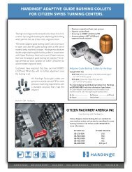
Pneumatic High-Force Collet Closer<br />
The Pneumatic High-Force Collet Closer is designed<br />
with a dual cylinder for greater available gripping<br />
force. This force can be regulated by adjusting the<br />
air pressure, but the force needs to be set according<br />
to levels below the maximum allowed for the<br />
workholding system. Much like the Fail-Safe closer,<br />
the total travel of this unit is .060"/1.5mm, but the<br />
through hole is only .311"/7.90mm. This means<br />
that the diameter variation or loading clearance of<br />
.015"/.4mm can be realized without adjustment and<br />
that the collet can be secured from the rear.<br />
2.4 Installing an Air-Actuated Collet Closer<br />
Figure 1 Figure 2<br />
5C High-Force Collet Closer<br />
FORCE CHART<br />
Air Pressure<br />
(psi)<br />
Drawbar Force<br />
(lbs)<br />
10 278<br />
20 557<br />
30 835<br />
40 1113<br />
50 1391<br />
60 1670<br />
70 1948<br />
80 2226<br />
90 2505<br />
100 2783<br />
Collet closer installation and alignment is critical if collet closers are going to be used during high-speed continuous<br />
rotation. It is recommended that collet closers are installed at the factory. However, in the event that a field installation<br />
of a closer is required, the following instructions can be used. Power down the system by first pushing the STOP<br />
button and turning off the control box or 4th-axis control. Remove any spindle tooling from the A2-4 spindle nose.<br />
Remove the button head screws holding the valve on the top of the closer adapter. Remove the snap ring from the rear<br />
of the closer and remove the slip ring and air valve as an assembly. If removing a fail-safe closer, use two dowel pins in<br />
the spanner holes on the back of the closer. These pins need to be long enough that a wrench can be placed across<br />
both pins and used to unthread the closer from the spindle. Two M10 bolts should be used in the face of the spindle<br />
to keep the spindle from rotating as the collet closer is unthreaded. If removing a high-force closer, use a strap wrench<br />
around the body of the closer to unthread it from the spindle. Replace the copper fittings with the correct size fitting<br />
for the closer you are going to install. Make sure the new collet closer has a draw bar adapter secured with lock-tite<br />
to the draw bar of the closer as seen in figure 1. Cut a piece of copper tubing to go from the closer to the valve. The<br />
fail-safe closer uses 1 /8" OD copper tubing and the high force closer uses ¼" OD copper tubing. You may have to do a<br />
couple of trial fittings to get the copper tubing the correct length. If installing a high-force closer, tighten with a strap<br />
wrench on the main body to approximately 30 ft-lbs. If installing a fail-safe closer, remove the rear slip ring by first<br />
removing the snap ring holding it on. Removing the slip ring will allow access to four spanner holes on the back face of<br />
the closer body. Insert dowel pins into the spanner holes that are long enough so that an adequate amount of the pins<br />
<strong>Hardinge</strong> Inc. One <strong>Hardinge</strong> <strong>Drive</strong>, Elmira, New York U.S.A. 14902-1507 800.843.8801 (Canada 800.468.5946) www.shophardinge.com<br />
Part No. BA -0009500-0160<br />
15