Hardinge B160A DD100 Direct-Drive Rotary User Manual
Hardinge B160A DD100 Direct-Drive Rotary User Manual
Hardinge B160A DD100 Direct-Drive Rotary User Manual

You also want an ePaper? Increase the reach of your titles
YUMPU automatically turns print PDFs into web optimized ePapers that Google loves.
<strong>DD100</strong> <strong>Direct</strong>-<strong>Drive</strong> <strong>Rotary</strong> Table Indexer <strong>User</strong> <strong>Manual</strong> B-160A<br />
Setup and Operation<br />
for the <strong>Hardinge</strong> ®<br />
<strong>DD100</strong> <strong>Direct</strong>-<strong>Drive</strong> <strong>Rotary</strong> Table Indexer<br />
Original U.S.A. Instructions<br />
<strong>Hardinge</strong> Inc. One <strong>Hardinge</strong> <strong>Drive</strong>, Elmira, New York U.S.A. 14902-1507 800.843.8801 (Canada 800.468.5946) www.shophardinge.com<br />
Part No. BA -0009500-0160<br />
1
2<br />
<strong>DD100</strong> <strong>Direct</strong>-<strong>Drive</strong> <strong>Rotary</strong> Table Indexer <strong>User</strong> <strong>Manual</strong> B-160A<br />
Thank you for purchasing a <strong>Hardinge</strong><br />
<strong>DD100</strong> <strong>Rotary</strong> Table Indexer! This <strong>User</strong>’s<br />
<strong>Manual</strong> is provided to assist you with setup<br />
procedures and to familiarize you with the<br />
features, specifications and maintenance<br />
recommendations of your unit.<br />
The mechanical indexing head can be maintained by the<br />
customer with proper cleaning and maintenance. Any<br />
necessary repairs required during the warranty period will<br />
be made at <strong>Hardinge</strong> Inc., or by a factory authorized<br />
representative.<br />
For best workholding results with this rotary table,<br />
<strong>Hardinge</strong> recommends <strong>Hardinge</strong> brand collets, 5C work-<br />
holding products, step chucks, and expanding collets.<br />
<strong>Hardinge</strong> Inc.<br />
One <strong>Hardinge</strong> <strong>Drive</strong><br />
Elmira, New York 14902-1507 U.S.A.<br />
p. 800.843.8801, or 607.378.4022<br />
p. 800.468.5946 (Canada)<br />
f. 607.734.3886<br />
<strong>Hardinge</strong> Inc. One <strong>Hardinge</strong> <strong>Drive</strong>, Elmira, New York U.S.A. 14902-1507 800.843.8801 (Canada 800.468.5946) www.shophardinge.com<br />
Part No. BA -0009500-0160
<strong>DD100</strong> <strong>Direct</strong>-<strong>Drive</strong> <strong>Rotary</strong> Table Indexer <strong>User</strong> <strong>Manual</strong> B-160A<br />
Table of Contents<br />
Safety Recommendations ........................................................................4<br />
1. Introduction<br />
1.1 Basic Description .....................................................................7<br />
1.2 High Stiffness Overall System ............................................................7<br />
1.3 Machinable Part Size ...................................................................7<br />
1.4 Spindle Clamp Option .................................................................8<br />
1.5 Features .............................................................................9<br />
1.6 Motor Thermostat ...................................................................10<br />
1.7 Specifications .......................................................................10<br />
1.8 Dimensions .........................................................................11<br />
2. Setup<br />
2.1 General Setup .......................................................................12<br />
2.2 Use of Collets, Chucks and Face Plates ...................................................13<br />
2.3 <strong>Hardinge</strong> Pneumatic High-Force and Fail-Safe Collet Closers .................................14<br />
2.4 Installing an Air-Actuated Collet Closer. . . . . . . . . . . . . . . . . . . . . . . . . . . . . . . . . . . . . . . . . . . . . . . . . . . 15<br />
2.5 Use of Collets with <strong>Hardinge</strong> Collet Closers ..............................................16<br />
2.6 Tooling Locations ....................................................................18<br />
3. Routine Maintenance<br />
3.1 Use of Oil- and Water-Soluble Coolants ..................................................19<br />
3.2 Clean Up ...........................................................................19<br />
3.3 Collet Key Replacement ...............................................................19<br />
4. One-Year Limited Warranty .................................................................19<br />
<strong>Hardinge</strong> Inc. One <strong>Hardinge</strong> <strong>Drive</strong>, Elmira, New York U.S.A. 14902-1507 800.843.8801 (Canada 800.468.5946) www.shophardinge.com<br />
Part No. BA -0009500-0160<br />
3
4<br />
<strong>DD100</strong> <strong>Direct</strong>-<strong>Drive</strong> <strong>Rotary</strong> Table Indexer <strong>User</strong> <strong>Manual</strong> B-160A<br />
Safety Recommendations<br />
READ COMPLETE INSTRUCTIONS CAREFULLY BEFORE OPERATING THIS UNIT. Note: Equipment refers to the<br />
rotary table indexer and/or machine it is used with.<br />
When this instruction book was printed, the information given was current. However, since we are constantly improving<br />
the design of our products, it is possible that the illustrations and descriptions may vary from the current unit.<br />
- WARNING -<br />
Occupational Safety and Health Administration (OSHA) Hazard Communication Standard 1910.1200, effective May<br />
25, 1986, and various state "employee right-to-know laws" require that information regarding chemicals used with this<br />
equipment be supplied to you. Refer to the applicable section of the Material Safety Data Sheets supplied with your unit<br />
when handling, storing, or disposing of chemicals.<br />
HARDINGE SAFETY RECOMMENDATIONS<br />
Your <strong>Hardinge</strong> machine is designed and built for maximum ease and safety of operation. However, some previously<br />
accepted shop practices may not reflect current safety regulations and procedures, and should be re-examined to insure<br />
compliance with the current safety and health standards.<br />
<strong>Hardinge</strong> Inc. recommends that all shop supervisors, maintenance personnel, and machine tool operators be advised<br />
of the importance of safe maintenance, setup, and operation of <strong>Hardinge</strong>-built equipment. Our recommendations are<br />
described below.<br />
READ THESE SAFETY RECOMMENDATIONS BEFORE PROCEEDING ANY FURTHER.<br />
ANYONE HAVING ACTIVE IMPLANTS (pacemakers) or having any other ferromagnetic prosthesis is not qualified<br />
to work with these kinds of devices, or to approach them. Keep at a safe distance from the motor.<br />
READ THE APPROPRIATE MANUAL OR INSTRUCTIONS before attempting operation or maintenance of the<br />
equipment. Make certain that you understand all instructions.<br />
DO NOT ALLOW the operation or repair of equipment by untrained personnel.<br />
CONSULT YOUR SUPERVISOR when in doubt as to the correct way to do a job.<br />
WEAR SAFETY GLASSES AND PROPER FOOT PROTECTION at all times. When necessary, wear respirator, helmet,<br />
gloves and ear muffs or plugs.<br />
DON’T OPERATE EQUIPMENT unless proper maintenance has been regularly performed and the equipment is known<br />
to be in good working order.<br />
WARNING or INSTRUCTION TAGS are mounted on the unit for your safety and information. Do not remove them<br />
or damage them.<br />
DO NOT ALTER THE EQUIPMENT to bypass any interlock, overload, disconnect, or other safety device.<br />
DO NOT OPERATE EQUIPMENT if unusual or excessive heat, noise, smoke or vibration occurs. Report any excessive<br />
or unusual vibration, sounds, smoke or heat as well as any damaged parts.<br />
LIFTING AND HANDLING OF THE UNIT should be done with full knowledge of the unit weight and using proper<br />
procedures.<br />
MAKE CERTAIN that the equipment is properly grounded. Consult National Electric Code and all local codes.<br />
REMOVE POWER from the unit by unplugging the power cord before attempting repair or maintenance. (Where<br />
Applicable)<br />
DON’T OPEN THE CONTROL BOX without consulting with <strong>Hardinge</strong>. (Where Applicable)<br />
DON’T TOUCH ELECTRICAL EQUIPMENT when hands are wet or when standing on a wet surface. (Where<br />
Applicable)<br />
REPLACE BLOWN FUSES with fuses of the same size and type as originally furnished. (Where Applicable)<br />
ASCERTAIN AND CORRECT the cause of a shutdown caused by overload heaters before restarting the machine.<br />
(Where Applicable)<br />
<strong>Hardinge</strong> Inc. One <strong>Hardinge</strong> <strong>Drive</strong>, Elmira, New York U.S.A. 14902-1507 800.843.8801 (Canada 800.468.5946) www.shophardinge.com<br />
Part No. BA -0009500-0160
<strong>DD100</strong> <strong>Direct</strong>-<strong>Drive</strong> <strong>Rotary</strong> Table Indexer <strong>User</strong> <strong>Manual</strong> B-160A<br />
Safety Recommendations (continued)<br />
KEEP THE AREA AROUND THE MACHINE well lit and dry.<br />
KEEP CHEMICAL AND FLAMMABLE MATERIAL away from electrical or operating equipment.<br />
HAVE THE CORRECT TYPE OF FIRE EXTINGUISHER handy when machining combustible material and keep chips<br />
clear of the work area.<br />
DON’T USE a toxic or flammable substance as a solvent cleaner or coolant.<br />
MAKE CERTAIN THAT PROPER GUARDING is in place and that all doors to the primary machine are closed and<br />
secured.<br />
DON’T OPEN GUARD DOORS of the primary machine while any machine component is in motion.<br />
MAKE SURE chucks, closers, fixture plates, and all other spindle-mounted workholding devices are properly mounted<br />
and secured before starting the unit or the machine.<br />
MAKE CERTAIN all tools are securely clamped in position before starting the unit or the machine.<br />
REMOVE ANY LOOSE PARTS OR TOOLS left on the unit or the machine or in the work area before operating<br />
the equipment. Always check the machine and work area for loose tools and parts especially after work has been<br />
completed by maintenance personnel.<br />
REMOVE CHUCK WRENCHES before starting the unit or the machine.<br />
BEFORE PRESSING THE CYCLE START PUSH BUTTON, make certain that proper functions are programmed and that<br />
all controls are set in the desired modes.<br />
KNOW WHERE ALL STOP push buttons are located in case of an emergency.<br />
MAKE CERTAIN that all guards are in good condition and are functioning properly before operating the equipment.<br />
INSPECT ALL SAFETY DEVICES AND GUARDS to make certain that they are in good condition and are functioning<br />
properly before the cycle is started.<br />
CHECK THE POSITION of any load/unload automation before pressing the Cycle Start push button.<br />
CHECK SETUP, TOOLING AND SECURITY OF THE WORKPIECE if the machine has been OFF for any length of time.<br />
DRY CYCLE a new setup to check for programming errors.<br />
MAKE CERTAIN that you are clear of any "pinch point" created by moving slides before starting the machine.<br />
DON’T OPERATE any equipment while any part of the body is in the proximity of a potentially hazardous area.<br />
DON’T REMOVE CHIPS with hands. Use a hook or similar device and make certain that all machine movements<br />
have ceased.<br />
BE CAREFUL of sharp edges when handling a newly machined workpiece.<br />
DON’T REMOVE OR LOAD a workpiece while any part of the equipment is in motion.<br />
DON’T OPERATE ANY EQUIPMENT while wearing rings, watches, jewelry, loose clothing, neckties or long hair not<br />
contained by a net or shop cap.<br />
DON’T ADJUST tooling or coolant hoses while the equipment is running.<br />
DON’T LEAVE tools, workpieces or other loose items where they can come in contact with a moving component<br />
of the equipment.<br />
DON’T CHECK finishes or dimensions of workpiece near running spindle or moving slides.<br />
DON’T JOG SPINDLE in either direction when checking threads with a thread gage.<br />
DON’T ATTEMPT to brake or slow the equipment with hands or any makeshift device.<br />
ANY ATTACHMENT, TOOL OR MACHINE MODIFICATION not obtained from <strong>Hardinge</strong> Inc. must be reviewed by<br />
a qualified safety engineer before installation.<br />
<strong>Hardinge</strong> Inc. One <strong>Hardinge</strong> <strong>Drive</strong>, Elmira, New York U.S.A. 14902-1507 800.843.8801 (Canada 800.468.5946) www.shophardinge.com<br />
Part No. BA -0009500-0160<br />
5
6<br />
<strong>DD100</strong> <strong>Direct</strong>-<strong>Drive</strong> <strong>Rotary</strong> Table Indexer <strong>User</strong> <strong>Manual</strong> B-160A<br />
Safety Recommendations (continued)<br />
USE CAUTION around exposed mechanisms and tooling especially when setting up. Be careful of sharp edges on tools.<br />
DON’T USE worn or defective hand tools. Use the proper size and type for the job being performed.<br />
USE ONLY a soft-faced hammer on tooling and fixtures.<br />
DON’T USE worn or broken tooling on machine.<br />
MAKE CERTAIN that all tool mounting surfaces are clean before mounting tools.<br />
INSPECT ALL CHUCKING DEVICES daily to make certain that they are in good operating condition. Replace any<br />
defective chuck before operating the machine.<br />
USE MAXIMUM ALLOWABLE gripping pressure on the chuck. Consider weight, shape and balance of the workpiece.<br />
DON’T EXCEED the rated capacity of the equipment.<br />
DON’T LEAVE the equipment unattended while it is operating.<br />
DON’T CLEAN the equipment with an air hose.<br />
KEEP TOTE PANS a safe distance from the machine. Don’t overfill the tote pans.<br />
DON’T LET STOCK project past the back end of the collet closer or equipment spindle without being adequately<br />
covered and properly supported.<br />
UNLESS OTHERWISE NOTED, all operating and maintenance procedures are to be performed by one person. To avoid<br />
injury to yourself and others, be sure that all personnel are clear of the equipment when opening or closing the coolant<br />
guard door and any access covers.<br />
FOR YOUR PROTECTION - WORK SAFELY<br />
DON’T OPERATE THE EQUIPMENT with damaged or worn electrical cables.<br />
VERIFY that the electrical cables are not restrained or pinched during full travel movement of the machine.<br />
<strong>Hardinge</strong> Inc. One <strong>Hardinge</strong> <strong>Drive</strong>, Elmira, New York U.S.A. 14902-1507 800.843.8801 (Canada 800.468.5946) www.shophardinge.com<br />
Part No. BA -0009500-0160
<strong>DD100</strong> <strong>Direct</strong>-<strong>Drive</strong> <strong>Rotary</strong> Table Indexer <strong>User</strong> <strong>Manual</strong> B-160A<br />
1. Introduction to the <strong>Hardinge</strong> ® <strong>DD100</strong> <strong>Direct</strong>-<strong>Drive</strong> <strong>Rotary</strong> Table Indexer<br />
1.1 Basic Description<br />
The <strong>Hardinge</strong> ® <strong>DD100</strong> <strong>Direct</strong>-<strong>Drive</strong> <strong>Rotary</strong> Table Indexer is ideal for rapid and accurate positioning of small parts in<br />
machining operations such as milling, drilling, tapping, contouring, spiral milling and grinding.<br />
The <strong>Hardinge</strong> <strong>DD100</strong> is a fully integrable, programmable, rotary positioning device. The mechanical indexing head<br />
holds the workpiece and is controlled by either the all-digital servo control or by a machine control as a true 4th axis.<br />
Positioning of the workpiece is accomplished by programming the angular movements into the memory of the servo<br />
control or by using the appropriate "G" codes and axis letter codes in the machine control just like a regular axis. It can<br />
be used as a slave to your CNC machine, as a master control unit in dedicated drilling operations, or as a true 4th axis<br />
to the machine. It can be used in the horizontal position or in some cases mounted vertically for face- and end-working<br />
applications. The <strong>DD100</strong> has a foot print similar to that of the <strong>Hardinge</strong> 5C <strong>Rotary</strong> Indexer and is mounted the same<br />
way. The rotary table indexer also has a spindle clamp option to help assist the motor for off-axis drilling and milling<br />
applications while maintaining a fixed position.<br />
Advantages of the 5C <strong>DD100</strong> <strong>Direct</strong>-<strong>Drive</strong> <strong>Rotary</strong> Table Indexer:<br />
• No Backlash<br />
• High Resolution Encoder <strong>Direct</strong>ly Mounted to Spindle<br />
• Long Life with Low Maintenance<br />
• Optimal Repeatability and Positioning Accuracy<br />
The <strong>DD100</strong> is offered with a 200 volt frameless (wraparound rare-earth) permanent magnet torque motor and meets<br />
the most rigorous industry codes. It carries the same spindle centerline (4.00"/101.6mm) and tool clearance as most<br />
other rotary products for direct replacement without program changes. It can be mounted with the spindle horizontal<br />
or in some cases vertical depending on application. Cable connectors meet the IP 65 splash code that states that they<br />
can be splashed with coolant and not leak. The spindle is hardened and ground for accuracy and has a rigid crossed<br />
roller bearing and a cylindrical roller to support heavy cutting forces. The unit is designed with a series of appropriate<br />
sealing systems including a direct bearing seal and a front cap seal with air purge to provide a longer bearing life.<br />
Positioning of the spindle is accomplished through a wraparound rare-earth permanent magnet torque motor that<br />
requires no mechanical gears. This type of motor requires no maintenance and will provide many years of smooth<br />
operating performance with zero backlash. The system is fitted with a means of liquid cooling to the motor to double<br />
the continuous torque. The high resolution encoder is mounted directly to the spindle to insure the highest available<br />
accuracy. Dependent upon the control system used, the <strong>DD100</strong> can yield a resolution of up to 655,360 counts per<br />
revolution.<br />
1.2 High Stiffness Overall System<br />
The <strong>DD100</strong> is inherently stiff due to its construction with the robust housing, crossed roller bearing in the front, and a<br />
tapered bore cylindrical roller bearing in the rear. Furthermore, the direct-drive motor offers a level of servo stiffness<br />
for the spindle that is superior to geared systems due to the elimination of gear backlash and other system compliances.<br />
The <strong>DD100</strong> servo gain is aimed more towards high-speed positioning than it is for contouring.<br />
1.3 Machinable Part Size<br />
The <strong>DD100</strong> <strong>Rotary</strong> Table Indexer is designed with a 5C spindle seat similar to the lathe spindle that <strong>Hardinge</strong> is noted<br />
for. The <strong>Hardinge</strong> <strong>DD100</strong> has been designed for those parts that can be conveniently gripped in any of the 5C gripping<br />
systems that <strong>Hardinge</strong> is also noted for. Typical parts are in the range of approximately 1"/25.4mm in diameter and generally<br />
not longer than 6"/152.4mm without the use of a tailstock. It is typical to speak in terms of the L/D ratio, which<br />
is the length divided by the part diameter. A 2"/50.8mm diameter part 6"/152.4mm long has an L/D ratio of 3:1. Part<br />
pieces with larger L/D ratios should be used with a tailstock up to a typical L/D ration of 6:1.<br />
Larger part sizes than those described above can be handled with additional support (i.e. tailstock, trunnion, etc.).<br />
When talking about machinable part size, inertia and torque play an important role. Any part and fixture combination<br />
should not exceed the maximum inertia of 0.015 kg.m 2 . This inertia should be calculated about the center of rotation<br />
<strong>Hardinge</strong> Inc. One <strong>Hardinge</strong> <strong>Drive</strong>, Elmira, New York U.S.A. 14902-1507 800.843.8801 (Canada 800.468.5946) www.shophardinge.com<br />
Part No. BA -0009500-0160<br />
7
8<br />
<strong>DD100</strong> <strong>Direct</strong>-<strong>Drive</strong> <strong>Rotary</strong> Table Indexer <strong>User</strong> <strong>Manual</strong> B-160A<br />
of the <strong>DD100</strong> because when a part's mass gets further from the center of rotation, its inertia increases. An unbalanced<br />
part should also not require a torque that exceeds the allowable torque of the motor shown in section 1.7 of this<br />
document. A part weighing 5 lbs at a distance of 6 inches from the center of the spindle would require 30 in-lbs or 2.5<br />
ft-lbs of torque to rotate. See examples below for light parts that have high inertia.<br />
Note: Larger inertial loads may require changing a few motor parameters to get the unit to run properly. If assistance<br />
is needed in calculating inertia, torque, or changing parameters, please contact your local <strong>Hardinge</strong> representative.<br />
����������������������������������������������<br />
�<br />
���������������<br />
�������������������������<br />
����������������������������������������������������������<br />
����������������������������������������<br />
����������������������������������������������������������������������<br />
Inertia vs. Weight vs. Required Torque to Spin Part<br />
Example A Example B<br />
Material: Steel<br />
Weight: 5.3 lbs/2.4 kg<br />
Material: Steel<br />
Weight: 2.5 lbs/1.1 kg<br />
Inertia about axis of Rotation: 2.7 lb-in2 Inertia about axis of Rotation: 17.8 lb-in2 /0.0008 kg-m2 /0.008 kg-m2 �����������������������������������������<br />
Torque required to turn Unbalanced Part: N/A Torque required to turn Unbalanced Part:<br />
(Balanced) 7.5 in-lbs/0.85 Nm<br />
Example A is a balanced part which is approximately twice as heavy as Example B, which is an unbalanced part. Notice<br />
that since Example A is balanced, the torque required to hold the part in position is negligible and its moment of inertia<br />
is very low. Since Example B is unbalanced, its moment of inertia is about 10 times larger than Example A even though<br />
it weighs about half as much. Also, note that torque is required to hold Example B in position.<br />
1.4 Spindle Clamp Option<br />
�������������������������������������������������<br />
AXIS OF ROTATION<br />
������������������������������������������������������������<br />
�<br />
���������������<br />
������������������������<br />
�����������������������������������������������������������<br />
�������������������������������������������������������������������������������<br />
The <strong>Hardinge</strong> ® <strong>DD100</strong> <strong>Direct</strong>-<strong>Drive</strong> <strong>Rotary</strong> Table Indexer is available with an optional fail-safe spindle clamp. This clamp<br />
allows the spindle to handle cutting forces equal to 100 ft-lb/136 Nm, allowing for greater cutting forces in the non-<br />
contouring mode of operation. The unit contains a pressure sensor that will prevent indexing in the event that air<br />
pressure drops below 85 psi to the clamp so that damage is prevented. Air is supplied to the clamp through the cable<br />
conduit and is either connected to the back of the control box or the machine air supply in the machine canopy wireway.<br />
When equipped with the <strong>Hardinge</strong> servo control, the clamp can be controlled automatically so that the clamp is<br />
engaged when the <strong>Rotary</strong> Table Indexer arrives at its programmed destination or it can be controlled with "G" codes.<br />
For ease of use, a "C" will appear on the display of the control whenever the clamp is engaged. There is a potential for<br />
a drop in air pressure if the air line supplying the <strong>Rotary</strong> Table Indexer is also supplying something else with air. If you<br />
receive a low pressure alarm, the first thing you should check is the air pressure supplied to the <strong>Rotary</strong> Table Indexer.<br />
Please note that even a momentary drop in air pressure can create an alarm situation.<br />
<strong>Hardinge</strong> Inc. One <strong>Hardinge</strong> <strong>Drive</strong>, Elmira, New York U.S.A. 14902-1507 800.843.8801 (Canada 800.468.5946) www.shophardinge.com<br />
�2.0<br />
0.6<br />
AXIS OF ROTATION<br />
�1.0<br />
3.5<br />
Part No. BA -0009500-0160
<strong>DD100</strong> <strong>Direct</strong>-<strong>Drive</strong> <strong>Rotary</strong> Table Indexer <strong>User</strong> <strong>Manual</strong> B-160A<br />
CAUTION: Never attempt to defeat the clamp protection logic as this may result in an opportunity for the system to<br />
rotate when the clamp is engaged. This will cause an overload fault and repeated attempts to operate in this manner<br />
may damage the clamp. The clamp requires a minimum of 85psi OF DRY FILTERED AIR to fully release the spindle and<br />
must be supplied to the unit even if the clamp is not going to be used.<br />
1.5 Features<br />
RIGID DESIGN<br />
Precision cross-roller bearing coupled with a tapered-bore cylindrical roller bearing will support heavy cutting forces<br />
on medium or small parts<br />
HARDENED AND GROUND SPINDLE<br />
Typical of the accurate long-life <strong>Hardinge</strong> lathe spindle<br />
WRAPAROUND RARE-EARTH PERMANENT MAGNET TORQUE MOTOR<br />
For very precise high-speed indexing with no backlash and high repeatability<br />
AUTOMATIC CIRCLE DIVISION (With <strong>Hardinge</strong> Servo Control)<br />
You can program a step that automatically divides a circle into any number of equal parts between 2 and 999<br />
STOP/FEED-HOLD (With <strong>Hardinge</strong> Servo Control)<br />
You can use the STOP to feed-hold spindle movement without losing position on restart<br />
INTERFACING (With <strong>Hardinge</strong> Servo Control)<br />
Most CNC mills can be interfaced quickly and easily by using a spare "M" function which provides a switch-closer as<br />
a signal between your mill and the control. The <strong>Hardinge</strong> servo control will provide a finish set of contacts to send a<br />
response back to the mill.<br />
LINEAR & SPIRAL MILLING (With <strong>Hardinge</strong> Servo Control)<br />
For semi 4th-axis capability<br />
MEMORY (With <strong>Hardinge</strong> Servo Control)<br />
A nonvolatile memory retains your program even when power is turned off, and remembers the current spindle<br />
position and step number<br />
PROGRAM STORAGE (With <strong>Hardinge</strong> Servo Control)<br />
Store and recall up to fifty different programs<br />
USER PARAMETERS (With <strong>Hardinge</strong> Servo Control)<br />
Some of the parameters can be changed by the user to alter a few of the basic features of the servo control.<br />
PROGRAMMING (With <strong>Hardinge</strong> Servo Control)<br />
Program to rotate the spindle clockwise or counterclockwise with step sizes from .001 to 9999.99 degrees.<br />
Using G83 & G84, continuous rotation is allowed. Contact <strong>Hardinge</strong> for maximum speeds based on duty cycle.<br />
ABSOLUTE OR INCREMENTAL PROGRAMMING (With <strong>Hardinge</strong> Servo Control)<br />
Up to 1000 different steps can be stored in memory and each step can be repeated (looped) 999 times<br />
RS-232 INTERFACE (With <strong>Hardinge</strong> Servo Control)<br />
For computer control of sending and receiving programs and controlling the rotary table indexer via the CNC control<br />
of host machine capable of RS-232 communication<br />
RESOLUTION<br />
Standard resolution of .001 degrees<br />
SIMPLE EDITING (With <strong>Hardinge</strong> Servo Control)<br />
Edit a program by simply writing over existing steps, or inserting or deleting a line (or several lines) between steps,<br />
with automatic program line renumbering<br />
<strong>Hardinge</strong> Inc. One <strong>Hardinge</strong> <strong>Drive</strong>, Elmira, New York U.S.A. 14902-1507 800.843.8801 (Canada 800.468.5946) www.shophardinge.com<br />
Part No. BA -0009500-0160<br />
9
10<br />
<strong>DD100</strong> <strong>Direct</strong>-<strong>Drive</strong> <strong>Rotary</strong> Table Indexer <strong>User</strong> <strong>Manual</strong> B-160A<br />
SUBROUTINES (With <strong>Hardinge</strong> Servo Control)<br />
Allows repeated sequences up to 999 times, saving programming time and memory space<br />
VARIABLE FEED RATES<br />
Variable from .001 deg./sec. to 4200 deg./sec. with <strong>Hardinge</strong> Servo Control up to 3600 deg/sec as true 4th axis<br />
ZERO RETURN (With <strong>Hardinge</strong> Servo Control)<br />
An "automatic home" position can be programmed to return the spindle to its original starting position from any point<br />
ONE-YEAR WARRANTY<br />
The <strong>Hardinge</strong> <strong>DD100</strong> <strong>Rotary</strong> Table System is provided with a 12-month, one-year warranty against any defects in<br />
material and workmanship.<br />
1.6 Motor Thermostat<br />
The motor is equipped with a thermostat that monitors the internal temperature in the motor windings. The<br />
thermostat is set to open at 85 degrees Celsius, which is well below the maximum temperature allowed in the<br />
motor windings.<br />
1.7 Specifications<br />
Spindle:<br />
Clamping Torque (ft-lb/Nm) 100/136<br />
Runout Max. (TIR) 0.0002"<br />
Backlash (arc/sec) 0<br />
Maximum RPM 450 with Servo Control @ 120 volt single phase<br />
700 with Servo Control @ 220 volt single phase<br />
600 as 4th Axis with 20 amp Fanuc <strong>Drive</strong>/Amplifier<br />
Rotational Speed (degrees/sec) 0.001 to 4200 with Servo Control<br />
0.001 to 3600 as Fanuc 4th Axis<br />
Spindle Nose A2-4, 5C<br />
Collets Standard 5C<br />
Spindle center-to-base (inch) 4.000" ± 0.001<br />
Indexing:<br />
Accuracy (arc/sec) ±3<br />
Repeatability (arc/sec) ±2<br />
Resolution (arc/sec) ±.077<br />
Max Rotation/Step (degree) 9999.99 or Continuous Using G83 or G84<br />
in the Servo Control<br />
Motor:<br />
Rare-Earth Permanent Magnet Torque Motor<br />
Maximum Torque (ft-lb/Nm) 28/38<br />
Continuous Air-Cooled 1 (ft-lb/Nm) 3.8/5.2<br />
Continuous Water-Cooled 1 (ft-lb/Nm) 7.5/10.2<br />
Operating Specifications:<br />
Duty Cycle 100% at full speed<br />
Operating Temperature (max. ambient) 104°F/40°C<br />
Power Rating 115±5% @ 10 amps 2<br />
Oil Requirements No Oil<br />
Air Requirements 85psi Minimum dry air for Optional Clamp<br />
85psi Maximum dry air for Optional Collet Closer<br />
Weight:<br />
<strong>Rotary</strong> Table Indexer (lb/kg) 65/29.48<br />
Control (lb/kg) 9.54/4.34<br />
1 - continuous torque available 24/7, 365 days, 2 - will vary according to motor requirements of the 4th-axis interface<br />
<strong>Hardinge</strong> Inc. One <strong>Hardinge</strong> <strong>Drive</strong>, Elmira, New York U.S.A. 14902-1507 800.843.8801 (Canada 800.468.5946) www.shophardinge.com<br />
Part No. BA -0009500-0160
<strong>DD100</strong> <strong>Direct</strong>-<strong>Drive</strong> <strong>Rotary</strong> Table Indexer <strong>User</strong> <strong>Manual</strong> B-160A<br />
Workholding:<br />
Collets-round (max. capacity) in/mm 1 1 /16"/26.98<br />
Collets-Hex (max. capacity) in/mm 29 /32"/23.01<br />
Collets-Square (max. capacity) in/mm ¾"/19.05<br />
Step Chucks (max. capacity) in/mm up to 4"/101.6<br />
3-Jaw Chucks (diameter) in/mm 4"/101.6<br />
Sure-Grip ® Expanding Collets in/mm 1 /8"-3"/3.17-76.20<br />
Fixture Plate-Collet Style (diameter) 3 3 /8"/85.72, 4 3 /8"/111.12<br />
Face Plate-Slotted with Angle Mounts (dia.) 6"/170mm<br />
Collet Stops (part positioning) YES<br />
1.8 Dimensions<br />
<strong>DD100</strong> <strong>Rotary</strong> Table Indexer Unit<br />
6 (152.3)<br />
9.38 (238)<br />
7.2<br />
(182.9)<br />
3.38 (86)<br />
14.35 (364.5)<br />
4±.001<br />
(101.6±.025)<br />
3±.0003<br />
(76.2±.007)<br />
5/8” OR 18MM (REMOVABLE LOCATING BUTTONS)<br />
9.99 (253.7)<br />
7.2 (183.8)<br />
12.90 (327.7)<br />
Side View with High-Force Collet Closer Side View with Fail-Safe Collet Closer<br />
FITTINGS FOR<br />
LIQUID COOLING<br />
THE MOTOR<br />
1.29 (32.8)<br />
9.09<br />
(229)<br />
<strong>Hardinge</strong> Inc. One <strong>Hardinge</strong> <strong>Drive</strong>, Elmira, New York U.S.A. 14902-1507 800.843.8801 (Canada 800.468.5946) www.shophardinge.com<br />
Part No. BA -0009500-0160<br />
11
12<br />
<strong>DD100</strong> <strong>Direct</strong>-<strong>Drive</strong> <strong>Rotary</strong> Table Indexer <strong>User</strong> <strong>Manual</strong> B-160A<br />
2. Set Up<br />
2.1 General Setup<br />
1. Fill out the warranty information by visiting "www.hardinge.com/rotarywarranty" on the internet.<br />
2. Place the rotary table indexer on the machine. Route the cable from the head so that it avoids tool changers and<br />
table edges. Cable slack must be provided for your machine’s movements. If the cable is cut, the motor or feed<br />
back system could fail prematurely. Replace a damaged cable immediately. Secure the rotary table to the machine’s<br />
T-slot table as shown below (upright or on its back). A special mounting plate will be needed to mount the unit on<br />
its back if using a high-force collet closer. T-nut packages are available for purchase for various T-slot tables.<br />
Kit includes (2) T-nuts, (2) bolts and (2) flat washers. Check to verify that all clearances are satisfied in full machine<br />
axis’ movements, and that there is no possibility of a collision.<br />
NOTE: End user is responsible for properly routing the cable. <strong>Hardinge</strong> accepts no responsibility for damages in<br />
cabling resulting from improper installation.<br />
3. Place the rotary table indexer in an area free from chips and coolant where air can circulate freely. Do not let<br />
chips pile up over the motor enclosure, as this would prevent proper cooling.<br />
4. Connect the <strong>DD100</strong> using one of the techniques as described in the <strong>Hardinge</strong> servo control or <strong>Hardinge</strong> 4th-axis<br />
manual which will be included with the mechanical unit.<br />
5. If adding a rotary table indexer to a <strong>Hardinge</strong> mill using a remote CNC cable or as a true 4th axis, refer to the<br />
instructions in the <strong>Hardinge</strong> 4th-axis manual or call your <strong>Hardinge</strong> service representative.<br />
6. If using the <strong>Hardinge</strong> servo control, secure it in its required placement. Do not cover any surface of the control,<br />
as it will quickly overheat. Do not place the unit on top of other hot electronic controls.<br />
a. The <strong>DD100</strong> is wired directly to the <strong>Hardinge</strong> servo control. For control box placement and cable routing,<br />
the cable will need to be disconnected and reconnected according to the instructions in the <strong>Hardinge</strong> Servo<br />
control manual.<br />
CAUTION: Never connect or disconnect these cables with the power on. Instant failure will result.<br />
b. Connect the AC line cord to a 120V AC grounded receptacle. The cord is a three-wire ground type and<br />
the ground must be connected. Power is 120VAC. The power service must supply a minimum of 15 amps<br />
continuously. Conduit wire must be 12 gauge or larger and fused for at least 20 amps. If an extension cord is<br />
to be used, use a three-wire ground type and the ground line must be connected. Avoid outlets that have large<br />
electric motors connected to them. Use only heavy-duty 12 gauge extension cords capable of 20 amp load. Do<br />
not exceed a length of 30 feet. Permanent installations should be hard-wired or installed with locking plugs.<br />
c. Semi-Fourth Axis: Connect the remote interface cable. See separate <strong>Hardinge</strong> Servo Control manual.<br />
<strong>Hardinge</strong> Inc. One <strong>Hardinge</strong> <strong>Drive</strong>, Elmira, New York U.S.A. 14902-1507 800.843.8801 (Canada 800.468.5946) www.shophardinge.com<br />
Part No. BA -0009500-0160
<strong>DD100</strong> <strong>Direct</strong>-<strong>Drive</strong> <strong>Rotary</strong> Table Indexer <strong>User</strong> <strong>Manual</strong> B-160A<br />
7. Connect air to the quick disconnect fitting on the back of the control box if unit is equipped with the spindle<br />
clamp option.<br />
CAUTION! If unit is equipped with the spindle clamp option, make sure air line connected to the control box is<br />
at least 85psi of dry filtered air.<br />
8. Connect air to the quick disconnect fitting on top of the rotary table if unit is equipped with a pneumatic<br />
collet closer. This will supply both the Collet Closer and Air Purge with air.<br />
Shown with<br />
Pneumatic<br />
Collet closer<br />
Caution! Never use more than 85psi with the fail-safe collet closer.<br />
9. If NOT using a pneumatic closer, connect air to the quick disconnect fitting on the side of the rotary table indexer<br />
for the air purge.<br />
10. Save the packing materials in case you need to ship the unit.<br />
11. At the end of the workday or shift, it is important to clean the rotary table indexer. The unit should be free of<br />
any chips or grime. Clean with a chip brush and apply a coat of rust preventative.<br />
CAUTION! Do not use an air gun around the front or rear seals. Chips may damage the seal if blown in with<br />
an air gun.<br />
NOTE: Prior to powering on the unit, read and understand the entire servo control or 4th axis manual.<br />
12. Initialization and homing of the unit is explained in the servo control and the 4th axis manuals.<br />
2.2 Use of Collets, Chucks, and Face Plates<br />
Quick<br />
Disconnect<br />
Fitting<br />
The unit accepts standard <strong>Hardinge</strong> ® 5C collets, step chucks, ID gripping collets, manual chucks, face plates and fixture<br />
plates. When inserting the collets, align the keyway on the collet with the pin inside the spindle. Push the collet in and<br />
turn the collet drawbar clockwise until proper collet tightness is obtained. Detailed collet installation instructions for<br />
pneumatic collet closers are provided later in this section. <strong>Manual</strong> chucks and face plates utilize the A2-4 tapered nose<br />
on the spindle. We recommend using chucks that are 4"/101.6mm diameter or smaller and weigh less than 20 pounds.<br />
Pay special attention when installing manual chucks. Always make sure that the tapered nose and the outside diameter<br />
of the spindle are free of dirt and chips.<br />
<strong>Hardinge</strong> Inc. One <strong>Hardinge</strong> <strong>Drive</strong>, Elmira, New York U.S.A. 14902-1507 800.843.8801 (Canada 800.468.5946) www.shophardinge.com<br />
Part No. BA -0009500-0160<br />
13
14<br />
<strong>DD100</strong> <strong>Direct</strong>-<strong>Drive</strong> <strong>Rotary</strong> Table Indexer <strong>User</strong> <strong>Manual</strong> B-160A<br />
2.3 <strong>Hardinge</strong> Pneumatic High-Force and Fail-Safe Collet Closers<br />
The <strong>DD100</strong> is NOT provided with a collet closer as standard. However, a collet closer assembly can be ordered for the<br />
rotary table indexer that utilizes one of the available pneumatic closers. <strong>Hardinge</strong> offers two pneumatic collet closers,<br />
the Pneumatic Fail-Safe and the Pneumatic High-Force. Both of these closers provide an opportunity for operational<br />
improvements by reducing operator fatigue and allowing for possible automation arrangements. Both closers utilize<br />
an original <strong>Hardinge</strong> concept of force amplification that has been historically proven to provide long life and effective<br />
operation even under demanding applications. The <strong>Hardinge</strong> force amplifier, which is an integral part of the design, is<br />
a simple approach that allows high actuation forces with shop air pressure. The fail-safe design is spring-close, air-toopen<br />
allowing it to grip a part if air is lost in the shop, which is why it is called a "fail-safe." The High-Force Closer is<br />
air-to-close and is spring return, so it does not grip a part without air, but has higher available gripping forces.<br />
The High-Force Pneumatic Closer design can be set for varying gripping force levels by simply adjusting the incoming air<br />
pressure within the specified operating range. The following closers will accommodate the complete range of <strong>Hardinge</strong><br />
5C tooling including step chucks and internal Sure-Grip ® expanding collet systems.<br />
Pneumatic Fail-Safe Collet Closer<br />
Fail-Safe Collet Closer High-Force Collet Closer<br />
The Pneumatic Fail-Safe Collet Closer is a spring-close, air-to-open design for fail-safe operation. The part will remain<br />
clamped at an optimum 5C draw bar force of 1760 lbs/7829 N even if loss of air occurs. To release the part piece, apply<br />
maximum air pressure of 85 psi. A draw bar travel of .060"/1.5mm allows varying part diameter of .015"/.4mm.<br />
The 1.08"/27.4mm through-hole accommodates long parts and thru-coolant. The collet closer is designed so that the<br />
<strong>Rotary</strong> Table Indexer can be positioned vertically without the use of a spacer.<br />
CAUTION! Don’t exceed 85 psi while operating Fail-Safe Collet Closer as it my cause fatal damage to the closer and<br />
may cause injury to operator. Increasing air pressure will not aid in gripping of part piece as gripping forces come from<br />
internal springs.<br />
<strong>Hardinge</strong> Inc. One <strong>Hardinge</strong> <strong>Drive</strong>, Elmira, New York U.S.A. 14902-1507 800.843.8801 (Canada 800.468.5946) www.shophardinge.com<br />
Part No. BA -0009500-0160
<strong>DD100</strong> <strong>Direct</strong>-<strong>Drive</strong> <strong>Rotary</strong> Table Indexer <strong>User</strong> <strong>Manual</strong> B-160A<br />
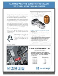
Pneumatic High-Force Collet Closer<br />
The Pneumatic High-Force Collet Closer is designed<br />
with a dual cylinder for greater available gripping<br />
force. This force can be regulated by adjusting the<br />
air pressure, but the force needs to be set according<br />
to levels below the maximum allowed for the<br />
workholding system. Much like the Fail-Safe closer,<br />
the total travel of this unit is .060"/1.5mm, but the<br />
through hole is only .311"/7.90mm. This means<br />
that the diameter variation or loading clearance of<br />
.015"/.4mm can be realized without adjustment and<br />
that the collet can be secured from the rear.<br />
2.4 Installing an Air-Actuated Collet Closer<br />
Figure 1 Figure 2<br />
5C High-Force Collet Closer<br />
FORCE CHART<br />
Air Pressure<br />
(psi)<br />
Drawbar Force<br />
(lbs)<br />
10 278<br />
20 557<br />
30 835<br />
40 1113<br />
50 1391<br />
60 1670<br />
70 1948<br />
80 2226<br />
90 2505<br />
100 2783<br />
Collet closer installation and alignment is critical if collet closers are going to be used during high-speed continuous<br />
rotation. It is recommended that collet closers are installed at the factory. However, in the event that a field installation<br />
of a closer is required, the following instructions can be used. Power down the system by first pushing the STOP<br />
button and turning off the control box or 4th-axis control. Remove any spindle tooling from the A2-4 spindle nose.<br />
Remove the button head screws holding the valve on the top of the closer adapter. Remove the snap ring from the rear<br />
of the closer and remove the slip ring and air valve as an assembly. If removing a fail-safe closer, use two dowel pins in<br />
the spanner holes on the back of the closer. These pins need to be long enough that a wrench can be placed across<br />
both pins and used to unthread the closer from the spindle. Two M10 bolts should be used in the face of the spindle<br />
to keep the spindle from rotating as the collet closer is unthreaded. If removing a high-force closer, use a strap wrench<br />
around the body of the closer to unthread it from the spindle. Replace the copper fittings with the correct size fitting<br />
for the closer you are going to install. Make sure the new collet closer has a draw bar adapter secured with lock-tite<br />
to the draw bar of the closer as seen in figure 1. Cut a piece of copper tubing to go from the closer to the valve. The<br />
fail-safe closer uses 1 /8" OD copper tubing and the high force closer uses ¼" OD copper tubing. You may have to do a<br />
couple of trial fittings to get the copper tubing the correct length. If installing a high-force closer, tighten with a strap<br />
wrench on the main body to approximately 30 ft-lbs. If installing a fail-safe closer, remove the rear slip ring by first<br />
removing the snap ring holding it on. Removing the slip ring will allow access to four spanner holes on the back face of<br />
the closer body. Insert dowel pins into the spanner holes that are long enough so that an adequate amount of the pins<br />
<strong>Hardinge</strong> Inc. One <strong>Hardinge</strong> <strong>Drive</strong>, Elmira, New York U.S.A. 14902-1507 800.843.8801 (Canada 800.468.5946) www.shophardinge.com<br />
Part No. BA -0009500-0160<br />
15
16<br />
<strong>DD100</strong> <strong>Direct</strong>-<strong>Drive</strong> <strong>Rotary</strong> Table Indexer <strong>User</strong> <strong>Manual</strong> B-160A<br />
stick out to put a wrench across them. Use a wrench to contact both dowel pins and turn the collet closer clockwise<br />
until tight.<br />
CAUTION! The High-Force Collet Closer relies on air pressure to maintain clamping force and will release if the air<br />
supply is accidentally removed. If this presents a fail-safe problem, then an air switch should be installed in-line to stop<br />
machining operations if the air supply should fail or purchase a fail-safe collet closer.<br />
2.5 Use of Collets With <strong>Hardinge</strong> Collet Closers<br />
NOTE: All collets must be free from burrs and in good condition.<br />
Collet Installation for High-Force Collet Closer<br />
To install a collet, align the collet keyway with the spindle key and insert the collet. Insert a 5 /16" hex wrench into the hex<br />
in the back of the draw tube, and turn the draw tube to engage the collet. Turn the draw tube until the collet grips the<br />
part, and then back off approximately 1 /4 turn. This will be a good starting point for fine tuning the grip range. If using a<br />
collet larger than the 5 /16" hex wrench, then the wrench can be inserted in the drawtube through the front of the collet<br />
for adjustment as well.<br />
<strong>Hardinge</strong> Inc. One <strong>Hardinge</strong> <strong>Drive</strong>, Elmira, New York U.S.A. 14902-1507 800.843.8801 (Canada 800.468.5946) www.shophardinge.com<br />
Part No. BA -0009500-0160
<strong>DD100</strong> <strong>Direct</strong>-<strong>Drive</strong> <strong>Rotary</strong> Table Indexer <strong>User</strong> <strong>Manual</strong> B-160A<br />
If the Collet is Sticking<br />
NOTE: To prevent excessive wear and collet sticking, make sure collets are in good condition and free from burrs.<br />
A light coat of Molybdenum grease on the collet wear surfaces will extend the life of the spindle and/or collet and<br />
help prevent sticking, especially when operating dry. Emergency collets are soft and are not recommended for long<br />
production runs. These collets will stick after prolonged use.<br />
When using the High-Force Collet Closer, releasing a collet is accomplished by removing the air supply. It is then<br />
pushed out by a heavy spring inside the collet closer.<br />
The High-Force Collet Closer uses shop air to pull the drawtube in and a heavy internal spring to push the draw<br />
tube out and release the collet. If, after repeated use, the spring will not push the collet out, use one of the following<br />
methods to remove the collet and lubricate the outside of the collet with a light grease film before reinserting:<br />
1. If the optional three-way air valve provided with the unit becomes clogged with contaminates, the exhaust airflow<br />
may be restricted, which may cause the collet to stick in the taper. If this situation arises, leave the valve in the<br />
clamped position, then connect and disconnect the air supply several times in rapid succession.<br />
2. If the above procedure does not free the collet, switch the valve to the unclamped position, then gently tap the<br />
back end of the drawtube with a plastic-faced mallet.<br />
<strong>Hardinge</strong> Inc. One <strong>Hardinge</strong> <strong>Drive</strong>, Elmira, New York U.S.A. 14902-1507 800.843.8801 (Canada 800.468.5946) www.shophardinge.com<br />
Part No. BA -0009500-0160<br />
17
18<br />
<strong>DD100</strong> <strong>Direct</strong>-<strong>Drive</strong> <strong>Rotary</strong> Table Indexer <strong>User</strong> <strong>Manual</strong> B-160A<br />
Collet Installation for Fail-Safe Collet Closer<br />
To install a collet, align the collet keyway with the spindle key and insert the collet. Use the provided knurled tool to<br />
turn the back of the collet closer drawtube. Turn the drawtube several times to get the collet started in the drawtube.<br />
Actuate the air valve to put air in the closer and move the drawtube to the forward position, or open position.<br />
Continue to turn the drawtube until the collet grips the part and back the collet out of the drawtube ¼ to ½ of a turn<br />
so that the part easily slips in and out of the collet. Never try to turn the drawtube while the collet is gripping a part<br />
as the friction is too high inside the closer to allow the drawtube to turn. Never under any circumstances should<br />
a wrench be put on the drawtube knurled tool to aid in tightening or loosening a collet. Any method of<br />
adjusting a collet other than by hand can break the closer and void any warranty by <strong>Hardinge</strong> Inc. If at any time the<br />
drawtube is too hard to turn by hand, call <strong>Hardinge</strong> for assistance, do not use other tools to try and break it free.<br />
2.6 Tooling Locations<br />
The <strong>DD100</strong> is equipped with tooling points in order to speed<br />
setups. One of the most time-consuming procedures in setup<br />
is aligning the head with the table. On the mounting surfaces<br />
there are two 0.500"/12.7mm bored holes on 3.000"/76.2mm<br />
centers. The holes on the bottom surface are parallel to the<br />
spindle within 0.001"/0.025mm per 6 inches/152.5mm and on<br />
center within ±0.001"/0.025mm. By boring machine holes in<br />
your tooling plate, setups become routine. Using the tooling<br />
holes will also prevent the head from shifting on the mill table<br />
when the part is subjected to heavy cutting forces. On CNC<br />
mills, a machined stepped plug of 0.500"/12.7mm diameter one<br />
side and 0.625"/15.9mm on the other comes with the <strong>Hardinge</strong><br />
head. The 0.625"/15.9mm diameter fits into the T-slot of the<br />
mill table. This will give quick parallel alignment that will be<br />
close enough for most jobs.<br />
NOTE: 0.625"/15.9mm and 18mm plugs are supplied as<br />
standard. Plugs can be turned down to another diameter to<br />
accommodate tables with different slot dimensions.<br />
6.61<br />
(168)<br />
<strong>Hardinge</strong> Inc. One <strong>Hardinge</strong> <strong>Drive</strong>, Elmira, New York U.S.A. 14902-1507 800.843.8801 (Canada 800.468.5946) www.shophardinge.com<br />
Part No. BA -0009500-0160
<strong>DD100</strong> <strong>Direct</strong>-<strong>Drive</strong> <strong>Rotary</strong> Table Indexer <strong>User</strong> <strong>Manual</strong> B-160A<br />
3. ROUTINE MAINTENANCE<br />
3.1 Use of Oil- and Water-Soluble Coolants<br />
For the use of oil- and water-soluble coolants, the following guidelines should be observed:<br />
3.2 Clean Up<br />
• DO NOT SUBMERGE THE UNIT IN COOLANTS. To the extent possible, direct the coolant lines to the<br />
work piece as opposed to directly upon the spindle seal area. Avoid high-pressure coolant applications<br />
where the pressure is above 200 psi. Some machining centers provide flood coolant at enormous rates so<br />
that the head is practically submerged. Throttle the flow back to appropriately match the application.<br />
• Inspect the cables and gaskets regularly for cuts or swelling. Damage must be repaired immediately.<br />
At the end of the workday or shift, it is important to clean the rotary table indexer. The head should be free of any<br />
chips or grime. Clean with a chip brush and apply a coat of rust preventative. Do not use an air gun around front or<br />
rear seals. Chips may damage seal if blown in with an air gun.<br />
3.3 Collet Key Replacement<br />
Remove the set screw in the collet key access hole located on the spindle and then remove the old collet key from the<br />
face of the spindle with a 3mm Allen wrench. Replace the collet key with <strong>Hardinge</strong> P/N RT-0000283K only using pipe<br />
sealant or thread locker/sealer when installing. Screw the collet key into the spindle until it begins to protrude into the<br />
inside diameter and turn it until the flat on the bottom of key is parallel to spindle centerline. Place a new <strong>Hardinge</strong><br />
collet into the spindle to test that key depth is adequate and then replace the set screw back into the key access hole<br />
using pipe sealant.<br />
NOTE: When using collet type workholding, never run the spindle without the collet key having been properly<br />
installed. Failure to do this may cause the collet to rotate in the spindle and possibly cause damage.<br />
4. One-Year Limited Warranty<br />
The <strong>Hardinge</strong> <strong>Direct</strong>-<strong>Drive</strong> <strong>DD100</strong> <strong>Rotary</strong> Table Indexer is provided with a 12-month, one-year warranty against any<br />
defects in material and workmanship. Specific details of the warranty can be found in the <strong>Hardinge</strong> Terms and<br />
Conditions document associated with the purchase agreement.<br />
<strong>Hardinge</strong> Inc. One <strong>Hardinge</strong> <strong>Drive</strong>, Elmira, New York U.S.A. 14902-1507 800.843.8801 (Canada 800.468.5946) www.shophardinge.com<br />
Part No. BA -0009500-0160<br />
19
<strong>Hardinge</strong> Inc. One <strong>Hardinge</strong> <strong>Drive</strong> | P.O. Box 1507 | Elmira, New York 14902-1507 USA<br />
USA: 800-843-8801 | Canada: 800-468-5946 | Fax: 607-734-3886<br />
To Order Online: www.shophardinge.com | Corporate Homepage: www.hardinge.com | E-mail: info@shophardinge.com | Live Online Support: www.shophardinge.com<br />
All specifications are subject to change without notice due to ongoing continuous improvement. All marks indicated by ® and are trademarks of <strong>Hardinge</strong> Inc.<br />
Instruction <strong>Manual</strong> B-160A • Litho in USA • ©<strong>Hardinge</strong> Inc. 2012