GD160LP Low-Profile Rotary Table - Hardinge Inc.
GD160LP Low-Profile Rotary Table - Hardinge Inc.
GD160LP Low-Profile Rotary Table - Hardinge Inc.

Create successful ePaper yourself
Turn your PDF publications into a flip-book with our unique Google optimized e-Paper software.
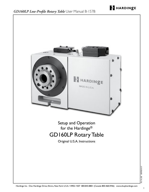
<strong>GD160LP</strong> <strong>Low</strong>-<strong>Profile</strong> <strong>Rotary</strong> <strong>Table</strong> User Manual B-157B<br />
Setup and Operation<br />
for the <strong>Hardinge</strong> ®<br />
<strong>GD160LP</strong> <strong>Rotary</strong> <strong>Table</strong><br />
Original U.S.A. Instructions<br />
<strong>Hardinge</strong> <strong>Inc</strong>. One <strong>Hardinge</strong> Drive, Elmira, New York U.S.A. 14902-1507 800.843.8801 (Canada 800.468.5946) www.shophardinge.com<br />
Part No. BB -0009500-0157<br />
1
2<br />
<strong>GD160LP</strong> <strong>Low</strong>-<strong>Profile</strong> <strong>Rotary</strong> <strong>Table</strong> User Manual B-157B<br />
Thank you for purchasing a <strong>Hardinge</strong><br />
<strong>GD160LP</strong> <strong>Low</strong>-<strong>Profile</strong> <strong>Rotary</strong> <strong>Table</strong>!<br />
This User’s Manual is provided to assist<br />
you with setup procedures and to<br />
familiarize you with the features, specifi-<br />
cations and maintenance recommenda-<br />
tions of your unit.<br />
The mechanical indexing head can be maintained by the<br />
customer with proper cleaning, lubrication, and maintenance.<br />
Any necessary repairs required during the warranty<br />
period will be made at <strong>Hardinge</strong> <strong>Inc</strong>. or by a factory<br />
authorized representative.<br />
<strong>Hardinge</strong> supplies a complete array of workholding<br />
products including manual chucks, fixture plates, face<br />
plates and Sjogren chucks. Custom-manufacturing is also<br />
available.<br />
<strong>Hardinge</strong> <strong>Inc</strong>.<br />
One <strong>Hardinge</strong> Drive<br />
Elmira, New York 14902-1507 U.S.A.<br />
p. 800.843.8801, or 607.378.4022<br />
p. 800.468.5946 (Canada)<br />
f. 607.734.3886<br />
<strong>Hardinge</strong> <strong>Inc</strong>. One <strong>Hardinge</strong> Drive, Elmira, New York U.S.A. 14902-1507 800.843.8801 (Canada 800.468.5946) www.shophardinge.com<br />
Part No. BB -0009500-0157
<strong>GD160LP</strong> <strong>Low</strong>-<strong>Profile</strong> <strong>Rotary</strong> <strong>Table</strong> User Manual B-157B<br />
<strong>Table</strong> of Contents<br />
Safety Recommendations ........................................................................4<br />
1. Introduction<br />
1.1 Description ...........................................................................7<br />
1.2 High Stiffness Overall System .............................................................7<br />
1.3 Machinable Part Size ....................................................................7<br />
1.4 Standard Spindle Clamp .................................................................8<br />
1.5 Features ..............................................................................9<br />
1.6 Specifications and General Requirements ..................................................10<br />
1.7 Dimensions ..........................................................................11<br />
2. Set Up<br />
2.1 General Setup ........................................................................12<br />
2.2 Use of the <strong>GD160LP</strong> Collet Closer .......................................................14<br />
2.3 Use of Collets, Manual Chucks, Face and Fixture Plates .......................................14<br />
2.4 Use of Collets with the <strong>Hardinge</strong> Collet Closer .............................................15<br />
2.5 Tooling Locations .....................................................................16<br />
3. Backlash Adjustment<br />
3.1 Measuring Backlash ....................................................................16<br />
3.2 Adjusting Backlash .....................................................................17<br />
4. Routine Maintenance<br />
4.1 Use of Oil- and Water-Soluble Coolants ...................................................19<br />
4.2 Lubrication ..........................................................................19<br />
4.3 Clean Up ............................................................................20<br />
5. One-Year Limited Warranty. . . . . . . . . . . . . . . . . . . . . . . . . . . . . . . . . . . . . . . . . . . . . . . . . . . . . . . . . . . . . . . . . . . 20<br />
<strong>Hardinge</strong> <strong>Inc</strong>. One <strong>Hardinge</strong> Drive, Elmira, New York U.S.A. 14902-1507 800.843.8801 (Canada 800.468.5946) www.shophardinge.com<br />
Part No. BB -0009500-0157<br />
3
4<br />
<strong>GD160LP</strong> <strong>Low</strong>-<strong>Profile</strong> <strong>Rotary</strong> <strong>Table</strong> User Manual B-157B<br />
Safety Recommendations<br />
READ COMPLETE INSTRUCTIONS CAREFULLY BEFORE OPERATING THIS UNIT. NOTE: Equipment refers to<br />
the rotary table and/or machine it is used with.<br />
When this instruction book was printed, the information given was current. However, since we are constantly improving<br />
the design of our products, it is possible that the illustrations and descriptions may vary from the system.<br />
- WARNING -<br />
Occupational Safety and Health Administration (OSHA) Hazard Communication Standard 1910.1200, effective May<br />
25, 1986, and various state "employee right-to-know laws" require that information regarding chemicals used with this<br />
equipment be supplied to you. Refer to the applicable section of the Material Safety Data Sheets supplied with your unit<br />
when handling, storing or disposing of chemicals.<br />
HARDINGE SAFETY RECOMMENDATIONS<br />
Your <strong>Hardinge</strong> rotary table is designed and built for maximum ease and safety of operation. However, some previously<br />
accepted shop practices may not reflect current safety regulations and procedures, and should be re-examined to<br />
insure compliance with the current safety and health standards.<br />
<strong>Hardinge</strong> <strong>Inc</strong>. recommends that all shop supervisors, maintenance personnel, and machine tool operators be advised<br />
of the importance of safe maintenance, setup and operation of <strong>Hardinge</strong>-built equipment. Our recommendations are<br />
described below.<br />
READ THESE SAFETY RECOMMENDATIONS BEFORE PROCEEDING ANY FURTHER.<br />
READ THE APPROPRIATE MANUAL OR INSTRUCTIONS before attempting operation or maintenance of the<br />
equipment. Make certain that you understand all instructions.<br />
DO NOT ALLOW the operation or repair of equipment by untrained personnel.<br />
CONSULT YOUR SUPERVISOR when in doubt as to the correct way to do a job.<br />
WEAR SAFETY GLASSES AND PROPER FOOT PROTECTION at all times. When necessary, wear respirator, helmet,<br />
gloves and ear muffs or plugs.<br />
DO NOT OPERATE EQUIPMENT unless proper maintenance has been regularly performed and the equipment is<br />
known to be in good working order.<br />
WARNING or INSTRUCTION TAGS are mounted on the unit for your safety and information. Do not remove them<br />
or damage them.<br />
DO NOT ALTER THE EQUIPMENT to bypass any interlock, overload, disconnect or other safety device.<br />
DO NOT OPERATE EQUIPMENT if unusual or excessive heat, noise, smoke, or vibration occurs. Report any excessive<br />
or unusual vibration, sounds, smoke or heat as well as any damaged parts.<br />
LIFTING AND HANDLING OF THE UNIT should be done with full knowledge of the unit weight and using proper<br />
procedures.<br />
MAKE CERTAIN that the equipment is properly grounded. Consult National Electric Code and all local codes.<br />
Remove power from the unit by unplugging the power cord before attempting repair or maintenance.<br />
(Where Applicable)<br />
DON’T OPEN THE CONTROL BOX without consulting with <strong>Hardinge</strong>. (Where Applicable)<br />
DON’T TOUCH ELECTRICAL EQUIPMENT when hands are wet or when standing on a wet surface.<br />
(Where Applicable)<br />
REPLACE BLOWN FUSES with fuses of the same size and type as originally furnished. (Where Applicable)<br />
<strong>Hardinge</strong> <strong>Inc</strong>. One <strong>Hardinge</strong> Drive, Elmira, New York U.S.A. 14902-1507 800.843.8801 (Canada 800.468.5946) www.shophardinge.com<br />
Part No. BB -0009500-0157
<strong>GD160LP</strong> <strong>Low</strong>-<strong>Profile</strong> <strong>Rotary</strong> <strong>Table</strong> User Manual B-157B<br />
Safety Recommendations (continued)<br />
ASCERTAIN AND CORRECT the cause of a shutdown caused by overload heaters before restarting the machine.<br />
(Where Applicable)<br />
KEEP THE AREA AROUND THE MACHINE well lit and dry.<br />
KEEP CHEMICAL AND FLAMMABLE MATERIAL away from electrical or operating equipment.<br />
HAVE THE CORRECT TYPE OF FIRE EXTINGUISHER handy when machining combustible material and keep chips<br />
clear of the work area.<br />
DON’T USE a toxic or flammable substance as a solvent cleaner or coolant.<br />
MAKE CERTAIN THAT PROPER GUARDING is in place and that all doors to the primary machine are closed<br />
and secured.<br />
DON’T OPEN GUARD DOORS of the primary machine while any machine component is in motion.<br />
MAKE SURE chucks, closers, fixture plates and all other spindle-mounted workholding devices are properly mounted<br />
and secured before starting the unit or the machine.<br />
MAKE CERTAIN all tools are securely clamped in position before starting the unit or the machine.<br />
REMOVE ANY LOOSE PARTS OR TOOLS left on the unit or the machine or in the work area before operating the<br />
equipment. Always check the machine and work area for loose tools and parts especially after work has been completed<br />
by maintenance personnel.<br />
REMOVE CHUCK WRENCHES before starting the unit or the machine.<br />
BEFORE PRESSING THE CYCLE START PUSH BUTTON, make certain that proper functions are programmed and that<br />
all controls are set in the desired modes.<br />
KNOW WHERE ALL STOOP push buttons are located in case of an emergency.<br />
CHECK THE LUBRICATION OIL LEVEL before operating the machine.<br />
MAKE CERTAIN that all guards are in good condition and are functioning properly before operating the equipment.<br />
INSPECT ALL SAFETY DEVICES AND GUARDS to make certain that they are in good condition and are functioning<br />
properly before the cycle is started.<br />
CHECK THE POSITION of any load/unload automation before pressing the CYCLE START push button.<br />
CHECK SETUP, TOOLING, AND SECURITY OF THE WORKPIECE if the machine has been OFF for any length<br />
of time.<br />
DRY CYCLE a new setup to check for programming errors.<br />
MAKE CERTAIN that you are clear of any "pinch point" created by moving slides before starting the machine.<br />
DON’T OPERATE any equipment while any part of the body is in the proximity of a potentially hazardous area.<br />
DON’T REMOVE CHIPS with hands. Use a hook or similar device and make certain that all machine movements have<br />
ceased.<br />
BE CAREFUL of sharp edges when handling a newly machined workpiece.<br />
DON’T REMOVE OR LOAD a workpiece while any part of the equipment is in motion.<br />
DON’T OPERATE ANY EQUIPMENT while wearing rings, watches, jewelry, loose clothing, neckties or long hair not<br />
contained by a net or shop cap.<br />
DON’T ADJUST tooling or coolant hoses while the equipment is running.<br />
DON’T LEAVE tools, workpieces or other loose items where they can come in contact with a moving component<br />
of the equipment.<br />
DON’T CHECK finishes or dimensions of workpiece near running spindle or moving slides.<br />
DON’T JOG SPINDLE in either direction when checking threads with a thread gage.<br />
<strong>Hardinge</strong> <strong>Inc</strong>. One <strong>Hardinge</strong> Drive, Elmira, New York U.S.A. 14902-1507 800.843.8801 (Canada 800.468.5946) www.shophardinge.com<br />
Part No. BB -0009500-0157<br />
5
6<br />
<strong>GD160LP</strong> <strong>Low</strong>-<strong>Profile</strong> <strong>Rotary</strong> <strong>Table</strong> User Manual B-157B<br />
Safety Recommendations (continued)<br />
DON’T ATTEMPT to brake or slow the equipment with hands or any makeshift device.<br />
ANY ATTACHMENT, TOOL OR MACHINE MODIFICATION not obtained from <strong>Hardinge</strong> <strong>Inc</strong>. must be reviewed by<br />
a qualified safety engineer before installation.<br />
USE CAUTION around exposed mechanisms and tooling especially when setting up. Be careful of sharp edges on tools.<br />
DON’T USE worn or defective hand tools. Use the proper size and type for the job being performed.<br />
USE ONLY a soft-faced hammer on tooling and fixtures.<br />
DON’T USE worn or broken tooling on machine.<br />
MAKE CERTAIN that all tool mounting surfaces are clean before mounting tools.<br />
INSPECT ALL CHUCKING DEVICES daily to make certain that they are in good operating condition. Replace any<br />
defective chuck before operating the machine.<br />
USE MAXIMUM ALLOWABLE gripping pressure on the chuck. Consider weight, shape and balance of the workpiece.<br />
DON’T EXCEED the rated capacity of the equipment.<br />
DON’T LEAVE the equipment unattended while it is operating.<br />
DON’T CLEAN the equipment with an air hose.<br />
KEEP TOTE PANS a safe distance from the machine. Don’t overfill the tote pans.<br />
DON’T LET STOCK project past the back end of the collet closer or equipment spindle without being adequately<br />
covered and properly supported.<br />
UNLESS OTHERWISE NOTED, all operating and maintenance procedures are to be performed by one person.<br />
To avoid injury to yourself and others, be sure that all personnel are clear of the equipment when opening or closing<br />
the coolant guard door and any access covers.<br />
FOR YOUR PROTECTION - WORK SAFELY<br />
DON’T OPERATE THE EQUIPMENT with damaged or worn electrical cables.<br />
VERIFY that the electrical cables are not restrained or pinched during full travel movement of the machine.<br />
<strong>Hardinge</strong> <strong>Inc</strong>. One <strong>Hardinge</strong> Drive, Elmira, New York U.S.A. 14902-1507 800.843.8801 (Canada 800.468.5946) www.shophardinge.com<br />
Part No. BB -0009500-0157
<strong>GD160LP</strong> <strong>Low</strong>-<strong>Profile</strong> <strong>Rotary</strong> <strong>Table</strong> User Manual B-157B<br />
1. Introduction<br />
1.1 Description<br />
The <strong>Hardinge</strong> ® <strong>GD160LP</strong> <strong>Rotary</strong> <strong>Table</strong> provides accurate and dependable positioning of small and medium parts in<br />
machining operations such as milling, drilling, tapping, contouring and spiral milling.<br />
The <strong>GD160LP</strong> is a fully integrable, programmable rotary positioning device that saves on workspace without sacrificing<br />
performance. The mechanical head holds the workpiece, which is positioned by programming angular movements into<br />
the all-digital servo control as a slave to a CNC machine or directly into a CNC control in a true 4th-axis setup. The<br />
mechanical head features an A2-4 spindle nose for spindle tooling compatibility with A2-4 spindle CNC lathes coupled<br />
with a precision ground 160mm slotted face plate. The spindle also houses a 5C collet seat, which accepts a variety of<br />
the 5C tooling that <strong>Hardinge</strong> is noted for.<br />
The <strong>Hardinge</strong> Spindle<br />
The <strong>GD160LP</strong> <strong>Rotary</strong> <strong>Table</strong> spindle is based on the industry standard A2-4 spindle design that has been used in<br />
<strong>Hardinge</strong> lathe production for over a century. The <strong>Hardinge</strong>-engineered mechanical elements guarantee the spindle will<br />
be accurate, repeatable, reliable and flexible to suit many different machining applications. The spindle carries a centerline<br />
from the machine bed of 5.00"/127mm, which keeps the unit small enough to fit on many machines.<br />
The spindle is hardened and ground for accuracy and has a rigid design with two large deep groove ball bearings to<br />
support heavy cutting forces. Positioning of the spindle is accomplished through a self-locking gear set and timing belt.<br />
1.2 High Stiffness Overall System<br />
The <strong>Hardinge</strong> <strong>GD160LP</strong> <strong>Rotary</strong> <strong>Table</strong> uses a high-quality hardened gear system with a 90:1 ratio achieved through<br />
gear and timing belt reduction. This type of gearing allows for an efficient transmission of high torque driving capability<br />
through the worm. The bearing set for this system consists of two large deep-groove ball bearings located on either<br />
side of the gear set. The bearings have been separated by the gear to increase the distance between the pivot points of<br />
the spindle, which greatly decreases the amount of system deflection caused by machining forces. This spindle is also<br />
equipped with a high-torque pneumatic fail-safe clamp, which prevents back driving and adds a considerable amount of<br />
stiffness. Stiffness or rigidity is one of the more important features of any system employed in the activity of machining<br />
operations and is the driving force for <strong>Hardinge</strong>-engineered rotary systems.<br />
1.3 Machinable Part Size<br />
The <strong>Hardinge</strong> <strong>GD160LP</strong> <strong>Rotary</strong> <strong>Table</strong> has been designed for those parts that can be conveniently clamped to the slotted<br />
face plate or conveniently gripped in any of the 5C gripping systems. Typical parts are in the range of approximately<br />
2"/50.8mm in diameter and generally not longer than 6"/152.4mm without the use of a tailstock. It is typical to speak<br />
in terms of the L/D ratio, which is the length divided by the part diameter. A 2"/50.8mm diameter part 6"/152.4mm<br />
long has an L/D ratio of 3:1. Part pieces with larger L/D ratios should be used with a tailstock up to a typical L/D<br />
ratio of 6:1.<br />
Larger part sizes than those described above can be handled with certain restrictions but should not exceed<br />
50lb/22.7kg in weight.<br />
<strong>Hardinge</strong> <strong>Inc</strong>. One <strong>Hardinge</strong> Drive, Elmira, New York U.S.A. 14902-1507 800.843.8801 (Canada 800.468.5946) www.shophardinge.com<br />
Part No. BB -0009500-0157<br />
7
8<br />
<strong>GD160LP</strong> <strong>Low</strong>-<strong>Profile</strong> <strong>Rotary</strong> <strong>Table</strong> User Manual B-157B<br />
1.4 Standard Spindle Clamp<br />
The <strong>GD160LP</strong> comes with a fail-safe spindle clamp that is standard from the factory. This clamp allows the spindle to<br />
handle cutting forces equal to 150 ft-lb/203 Nm, allowing for greater cutting forces in the non-contouring mode of<br />
operation. The unit contains an air sensor that will prevent rotation in the event that air pressure drops below 85 psi<br />
to the clamp so that damage is prevented. Air is supplied to the clamp via a quick-disconnect fitting on top of the<br />
motor cover. When operated with the <strong>Hardinge</strong> servo control, the clamp can be controlled automatically so that the<br />
clamp is engaged when the rotary table arrives at its programmed destination or it can be controlled with "G" codes.<br />
For ease of use, a "C" will appear on the display of the control whenever the clamp is engaged.<br />
There is a potential for a drop in air pressure if the air line supplying the rotary table with air is also supplying something<br />
else with air. If you receive a low pressure alarm, the first thing you should check is the air pressure supplied to<br />
the rotary table. Please note that even a momentary drop in air pressure can create an alarm situation.<br />
CAUTION: Never attempt to defeat the clamp protection logic, as this may result in an opportunity for the system to<br />
rotate when the clamp is engaged. This will cause an overload fault and repeated attempts to operate in this manner<br />
may damage the clamp. Clamp requires a minimum of 85psi and a maximum of 100psi of dry filtered air to fully release<br />
the spindle.<br />
<strong>Hardinge</strong> <strong>Inc</strong>. One <strong>Hardinge</strong> Drive, Elmira, New York U.S.A. 14902-1507 800.843.8801 (Canada 800.468.5946) www.shophardinge.com<br />
Part No. BB -0009500-0157
<strong>GD160LP</strong> <strong>Low</strong>-<strong>Profile</strong> <strong>Rotary</strong> <strong>Table</strong> User Manual B-157B<br />
1.5 Features<br />
RIGID DESIGN<br />
<strong>Inc</strong>reased distance between large bearings support heavy cutting forces on large or small parts<br />
HARDENED AND GROUND SPINDLE<br />
For higher accuracy<br />
DUAL DEEP GROOVE BALL BEARINGS<br />
Support heavy cutting forces<br />
AUTOMATIC CIRCLE DIVISION (With <strong>Hardinge</strong> Servo Control)<br />
You can program a step that automatically divides a circle into any number of equal parts between 2 and 999<br />
STOP/FEED-HOLD (With <strong>Hardinge</strong> Servo Control)<br />
You can use the STOP to feed-hold spindle movement without losing position on restart<br />
FAST SETUPS (With <strong>Hardinge</strong> Servo Control)<br />
All connectors are "quick-disconnect", ensuring fast and easy setups<br />
INTERFACING (With <strong>Hardinge</strong> Servo Control)<br />
Most CNC mills can be interfaced quickly and easily by using a spare "M" function, which provides a switch-closer<br />
as a signal between your mill and the control<br />
LINEAR & SPIRAL MILLING (With <strong>Hardinge</strong> Servo Control)<br />
For semi fourth-axis capability<br />
MEMORY (With <strong>Hardinge</strong> Servo Control)<br />
A nonvolatile memory retains your program even when power is turned off – and remembers the current spindle<br />
position and step number when the servo is stopped<br />
PROGRAM STORAGE (With <strong>Hardinge</strong> Servo Control)<br />
Store and recall up to fifty different programs<br />
PROGRAMMABLE PARAMETERS (With <strong>Hardinge</strong> Servo Control)<br />
You can alter many of the basic features by performing basic programming<br />
PROGRAMMING (With <strong>Hardinge</strong> Servo Control)<br />
Program to rotate the spindle clockwise or counterclockwise with step sizes from .001 to 9999.99 degrees.<br />
Using G83 & G84, continuous rotation is allowed. Contact <strong>Hardinge</strong> for maximum speeds based on duty cycle.<br />
ABSOLUTE OR INCREMENTAL PROGRAMMING (With <strong>Hardinge</strong> Servo Control)<br />
Up to 1000 different steps can be stored in memory, and each step can be repeated (looped) 999 times<br />
RS-232 INTERFACE (With <strong>Hardinge</strong> Servo Control)<br />
For computer control of sending and receiving programs, and controlling the rotary table via the CNC control of host<br />
machine capable of RS-232 communication<br />
RESOLUTION<br />
Standard resolution of .001 degrees<br />
SIMPLE EDITING (With <strong>Hardinge</strong> Servo Control)<br />
Edit a program by simply writing over existing steps, or inserting or deleting a step, (or several steps) with automatic<br />
program step renumbering<br />
SUBROUTINES (With <strong>Hardinge</strong> Servo Control)<br />
Allows repeated sequences up to 999 times, saving programming time and memory space<br />
VARIABLE FEED RATES<br />
Variable from .001 deg./sec. to 240 deg./sec.<br />
ZERO RETURN (With <strong>Hardinge</strong> Servo Control)<br />
An "automatic home" position can be programmed to return the spindle to its original starting position from any point<br />
ONE-YEAR WARRANTY<br />
The <strong>Hardinge</strong> <strong>GD160LP</strong> <strong>Low</strong>-<strong>Profile</strong> <strong>Rotary</strong> <strong>Table</strong> is provided with a one-year warranty against any defects in material<br />
and workmanship.<br />
<strong>Hardinge</strong> <strong>Inc</strong>. One <strong>Hardinge</strong> Drive, Elmira, New York U.S.A. 14902-1507 800.843.8801 (Canada 800.468.5946) www.shophardinge.com<br />
Part No. BB -0009500-0157<br />
9
10<br />
<strong>GD160LP</strong> <strong>Low</strong>-<strong>Profile</strong> <strong>Rotary</strong> <strong>Table</strong> User Manual B-157B<br />
1.6 Specifications<br />
Spindle<br />
Torque (ft-lb/Nm) 73/99<br />
Spindle Runout Max (TIR) 0.0002"<br />
Faceplate Runout Max 0.0002"<br />
Faceplate Perpendicularity 0.0002"<br />
Backlash (arc/sec) 40<br />
Speed (degrees/sec) 0.001 to 240<br />
RPM Maximum 40<br />
Load Support Dual Deep-Groove Ball Bearings<br />
Spindle Nose A2-4<br />
Spindle center to base (inch/mm) 5.000"/127 ± 0.001/.025<br />
Positioning:<br />
Accuracy (arc/sec) ± 20*<br />
Repeatability (arc/sec) ±5<br />
Resolution (degree) 0.001<br />
Max Rotation/Step (degree) Continuous<br />
Gear Diameter (inch/mm) 3.65/92.7<br />
Motor<br />
Type (hp/kW DC servo) 0.78/0.58 (with <strong>Hardinge</strong> Servo Control)<br />
Clamping Torque 150 ft-lb / 203 Nm<br />
Gear Ratio (gear set) 90:1<br />
L-pitch Timing Belt Frequency (Hz) 251-263<br />
Operating Specifications<br />
Duty Cycle 90% at full speed without tailstock<br />
Operating Temperature / Humidity 41 to 104°F / 5 to 40°C, 85% Relative Humidity<br />
Power Rating 120Vac, 60Hz, 15A or 230Vac, 50Hz, 10A<br />
Oil Requirements MOBILGEAR 600 XP 220<br />
Air Pressure Range for Clamp (psi/bar) 85min-100max/5.9min-6.9max (dry filtered air)<br />
Weight<br />
<strong>Rotary</strong> <strong>Table</strong> (lb/kg) 120/5.4<br />
Workholding 5C<br />
Collets-Round (maximum capacity) inch/mm 11 /16"/26.98<br />
Collets-Hex (maximum capacity) inch/mm<br />
29 /32"/23.01<br />
Collets-Square (maximum capacity) inch/mm<br />
3 /4"/19.05<br />
Step Chucks-Regular Depth (max. capacity) inch/mm Up to 4"/102.8<br />
Step Chucks-Extra Depth (max. capacity) inch/mm Up to 4"/102.8<br />
3-Jaw Manual Chucks (diameter) inch/mm 5"/127, 6"/152.4<br />
Sure-Grip ® Expanding Collets-Collet Style inch/mm 1 /8"-3"/3.17-76.2<br />
Slotted Face Plate (diameter) inch/mm 6.299/160<br />
Collet Stops for Part Positioning YES<br />
* Accuracies can be improved with electronic compensation<br />
<strong>Hardinge</strong> <strong>Inc</strong>. One <strong>Hardinge</strong> Drive, Elmira, New York U.S.A. 14902-1507 800.843.8801 (Canada 800.468.5946) www.shophardinge.com<br />
Part No. BB -0009500-0157
<strong>GD160LP</strong> <strong>Low</strong>-<strong>Profile</strong> <strong>Rotary</strong> <strong>Table</strong> User Manual B-157B<br />
1.7 Dimensions<br />
<strong>GD160LP</strong> <strong>Rotary</strong> <strong>Table</strong><br />
MADE IN U.S.A.<br />
6.31 (160)<br />
10.77 (273) 3.50<br />
(80)<br />
14.27 (363)<br />
.531 (13.5)<br />
5 (127)<br />
±.001 (.025)<br />
.95 (24)<br />
4.123 (104.7)<br />
.875 (22.2)<br />
1 (25.4)<br />
1.25 (33)<br />
8.40 (213)<br />
5.87 (149)<br />
2.31 (59)<br />
<strong>Hardinge</strong> <strong>Inc</strong>. One <strong>Hardinge</strong> Drive, Elmira, New York U.S.A. 14902-1507 800.843.8801 (Canada 800.468.5946) www.shophardinge.com<br />
3.45<br />
(88)<br />
10.02 (255)<br />
The <strong>GD160LP</strong> can be ordered with the motor on either side of the unit. If the unit is ordered with the motor in<br />
the standard orientation, the motor is on the left looking at the faceplate as shown above and counterclockwise is<br />
the positive direction. The drive dog will be in the 2 o’clock position when the rotary is in the zero position. If the<br />
unit is ordered with the motor on the right-hand side of the unit, then the spindle will move clockwise when<br />
programmed to move in the positive direction and the drive dog will be in the 8 o’clock position when the rotary is<br />
in the zero position.<br />
NOTE: The <strong>Hardinge</strong> servo control and most machine control parameters can be changed to make either clockwise<br />
or counter-clockwise the positive direction.<br />
Part No. BB -0009500-0157<br />
11
12<br />
<strong>GD160LP</strong> <strong>Low</strong>-<strong>Profile</strong> <strong>Rotary</strong> <strong>Table</strong> User Manual B-157B<br />
2. Set Up<br />
2.1 General Setup<br />
1. Fill out the warranty information by visiting "www.hardinge.com/rotarywarranty" on the internet.<br />
2. Place the <strong>GD160LP</strong> <strong>Rotary</strong> <strong>Table</strong> on the machine. Route the cable from the head so that it avoids tool<br />
changers and table edges. Cable slack must be provided for your machine’s movements. If the cable is cut, the<br />
motor will fail prematurely. Replace a damaged cable immediately. Use a cable retractor for excessive cable<br />
slack. Secure the rotary table to the machine’s T-slot table as shown below (upright or on its back). T-nut<br />
packages are available for purchase for various T-slot tables. Kit includes (2) T-nuts, (2) bolts and (2) flat washers.<br />
Mounting the rotary table on its back will require a special vertical mounting plate. Check to verify that<br />
all clearances are satisfied in full machine axes movements and that there is no possibility of a collision.<br />
3. Place the <strong>GD160LP</strong> in an area free from chips and coolant where air can circulate freely. Do not let chips pile<br />
up over the motor enclosure, as this would prevent proper cooling.<br />
4. Connect the <strong>GD160LP</strong> using one of the techniques as described in the <strong>Hardinge</strong> servo control or <strong>Hardinge</strong><br />
4th-axis manual, which will be included with the mechanical unit.<br />
5. Route the cable over the back of the mill sheet metal (if using <strong>Hardinge</strong> Servo Control).<br />
6. If adding a rotary table to a <strong>Hardinge</strong> mill using a remote CNC cable, or as a true 4th axis, the settings must<br />
be set for the specific unit. Refer to the instructions in the <strong>Hardinge</strong> 4th-axis manual or call the <strong>Hardinge</strong><br />
service department.<br />
7. If using the <strong>Hardinge</strong> servo control, secure it in its required placement. Do not cover any surface of the<br />
control, as it will quickly overheat. Do not place the unit on top of other hot electronic controls.<br />
<strong>Hardinge</strong> <strong>Inc</strong>. One <strong>Hardinge</strong> Drive, Elmira, New York U.S.A. 14902-1507 800.843.8801 (Canada 800.468.5946) www.shophardinge.com<br />
Part No. BB -0009500-0157
<strong>GD160LP</strong> <strong>Low</strong>-<strong>Profile</strong> <strong>Rotary</strong> <strong>Table</strong> User Manual B-157B<br />
7a. Connect the two cables from the rotary table to the controller in the appropriate locations.<br />
CAUTION: Never connect or disconnect these cables with the power on. Instant failure will result.<br />
7b. Connect the AC line cord to a 120V AC grounded receptacle. The cord is a three-wire ground type<br />
and the ground must be connected. Power is 120VAC. The power service must supply a minimum of<br />
15 amps continuously. Conduit wire must be 12 gauge or larger and fused for at least 20 amps. If using<br />
an extension cord, use a three-wire ground type and the ground line must be connected. Use only<br />
heavy-duty 12-gauge extension cords capable of 20 amp load. Avoid outlets that have large electric<br />
motors connected to them. Do not exceed a length of 30 feet. Permanent installations should be<br />
hard-wired or installed with locking plugs.<br />
7c. Semi-Fourth Axis: Connect the remote interface cable. See the separate <strong>Hardinge</strong> servo control<br />
manual for more information (included with the unit).<br />
8. Connect a minimum of 85 psi or maximum of 100psi of dry filtered air to the quick-disconnect fitting on top<br />
of the motor cover for releasing the spindle clamp.<br />
Quick-disconnect<br />
Quick-disconnect for clamp function<br />
for collet closer<br />
CAUTION: Never operate the <strong>GD160LP</strong> without a minimum of 85 psi or maximum of 100psi dry filtered air<br />
connected to the fitting or mechanical damage may occur.<br />
<strong>Hardinge</strong> <strong>Inc</strong>. One <strong>Hardinge</strong> Drive, Elmira, New York U.S.A. 14902-1507 800.843.8801 (Canada 800.468.5946) www.shophardinge.com<br />
Part No. BB -0009500-0157<br />
13
14<br />
<strong>GD160LP</strong> <strong>Low</strong>-<strong>Profile</strong> <strong>Rotary</strong> <strong>Table</strong> User Manual B-157B<br />
9. Check the oil level. If it is low, add oil. Use MOBILGEAR 600 XP 220 only.<br />
10. Save the packing materials in case you need to ship the unit.<br />
11. At the end of the workday or shift, it is important to clean the rotary table. The rotary table should be free of<br />
any chips or grime. Clean with a chip brush and apply a coat of rust preventative.<br />
CAUTION! Do not use an air gun around the front or rear seals. Chips may damage the seal if blown in<br />
with an air gun.<br />
NOTE: Prior to powering on the control, read and understand the entire control or 4th-axis manual.<br />
12. Turn on the mill (and servo control if applicable) and home the rotary table by pressing the zero return<br />
button. The rotary table homes in the counterclockwise direction as viewed from the spindle.<br />
2.2 Use of the <strong>GD160LP</strong> Collet Closer (Optional)<br />
The <strong>GD160LP</strong> collet closer has a 1.08"/27.4mm through-hole design with pneumatic open and close. The through-hole<br />
can be used for through-spindle coolant or for holding long parts or material. The pneumatic closer has a .375"/9.5mm<br />
stroke. Since the closer is actuated both forward and backwards pneumatically, the air pressure can be regulated to get<br />
different desired drawbar forces for specific gripping applications. An example of the adjusted drawbar forces is below.<br />
<strong>GD160LP</strong> Collet Closer Drawbar Force Chart<br />
Air Pressure Drawbar Pull Force Drawbar Push Force<br />
(psi) (lbs) (lbs)<br />
70 1618 1500<br />
80 1850 1713<br />
90 2080 1927<br />
100 2312 2141<br />
2.3 Use of Collets, Sure-Grip ® Expanding Collets, Manual Chucks, Face and Fixture Plates<br />
The unit accepts standard <strong>Hardinge</strong> ® 5C collets, step chucks, ID gripping collets, manual and power chucks, face and<br />
fixture plates. When inserting the collet, align the keyway on the collet with the key inside the spindle. Push the collet<br />
in and turn the collet closer drawbar clockwise until proper collet tightness is obtained.<br />
Manual chucks and face plates utilize the A2-4 nose on the spindle. We recommend using manual or power chucks that<br />
are 6"/152.4mm in diameter, or smaller, and weigh less than 20 pounds. Pay special attention when installing chucks. Always<br />
make sure that the spindle nose and face of the spindle are free of dirt and chips. Apply a thin coating of oil to the<br />
spindle. Bolt the chuck to the spindle using the supplied bolts, making sure to tighten the bolts to the specified torque.<br />
<strong>Hardinge</strong> <strong>Inc</strong>. One <strong>Hardinge</strong> Drive, Elmira, New York U.S.A. 14902-1507 800.843.8801 (Canada 800.468.5946) www.shophardinge.com<br />
Part No. BB -0009500-0157
<strong>GD160LP</strong> <strong>Low</strong>-<strong>Profile</strong> <strong>Rotary</strong> <strong>Table</strong> User Manual B-157B<br />
2.4 Use of Collets with the <strong>Hardinge</strong> Collet Closer<br />
NOTE: All collets must be free from burrs and in good condition<br />
To install a collet, first make sure the (3) three M6 bolts in the back of the drawbar are completely backed out of the<br />
piston. Align the collet keyway with the spindle key and insert the collet until the collet threads contact the end of the<br />
drawbar. If the collet goes all the way in the spindle without touching the drawbar threads, the closer may have to be<br />
actuated in the opposite direction that it is currently in. Turn the drawbar until the collet grips the part and then back<br />
the collet out ¼ turn of the drawbar until the M6 bolts on the back of the drawbar line up with the tapped holes in the<br />
piston. Tighten all (3) three of the M6 bolts back down before actuating the collet closer.<br />
Back of <strong>Rotary</strong> <strong>Table</strong> showing Optional Collet Closer<br />
Drawbar with (3)<br />
three M6 bolts<br />
NOTE: To prevent excessive wear and collet sticking, make sure collets are in good condition and free from burrs.<br />
A light coat of Molybdenum grease on the collet wear surfaces will extend the life of the spindle and/or collet and help<br />
prevent sticking, especially when operating dry.<br />
<strong>Hardinge</strong> <strong>Inc</strong>. One <strong>Hardinge</strong> Drive, Elmira, New York U.S.A. 14902-1507 800.843.8801 (Canada 800.468.5946) www.shophardinge.com<br />
Part No. BB -0009500-0157<br />
15
16<br />
<strong>GD160LP</strong> <strong>Low</strong>-<strong>Profile</strong> <strong>Rotary</strong> <strong>Table</strong> User Manual B-157B<br />
2.5 Tooling Locations<br />
MADE IN U.S.A.<br />
5 (127)<br />
±.001 (.025)<br />
The <strong>GD160LP</strong> <strong>Rotary</strong> <strong>Table</strong> is equipped with tooling points in order to speed up setups. One of the most timeconsuming<br />
procedures in setup is aligning the head with the table. On the mounting surfaces, there are two 0.500"/<br />
12.7mm bored holes on 1.250"/31.75mm 10.77 centers. (273) The holes 3.50 on the bottom .95 (24) surface are parallel<br />
1.25<br />
to<br />
(33)<br />
the spindle within 2.31 (59)<br />
(80)<br />
0.001"/0.25mm per 6 inches/152.4mm and 14.27 on the (363) center within ±0.001"/0.25mm. By boring machine holes 5.87 in your (149)<br />
tooling plate, setups become routine. Using the tooling holes will also prevent the head from shifting on the mill table<br />
when the part is subjected to heavy cutting forces. On CNC mills, a machined stepped plug of 0.500"/12.7mm diameter<br />
on one side, and 0.625"/15.87mm on the other, comes with the <strong>Hardinge</strong> rotary table. The 0.625"/15.87mm diameter<br />
fits into the T-slot of the mill table. This will give quick parallel alignment that will be adequate for most jobs.<br />
.531 (13.5)<br />
4.123 (104.7)<br />
.875 (22.2)<br />
1 (25.4)<br />
NOTE: 0.625"15.87mm and 18mm plugs are supplied as standard. Plugs can be turned down to another diameter to<br />
accommodate tables with different slot dimensions.<br />
3. Backlash Adjustment<br />
3.1 Measuring Backlash<br />
Make sure the spindle clamp is released prior to attempting<br />
to measure backlash. To measure backlash, you need the use<br />
of a .0001 inch indicator and a magnetic v-block or magnetic<br />
block. Home the rotary table, as that is where backlash is<br />
checked at the <strong>Hardinge</strong> factory. Place the magnetic block<br />
on the rotary table face plate so that the top of the block is<br />
parallel to the machine bed and in line with the spindle<br />
centerline as shown in the picture. Setup the indicator so<br />
that it is measuring the top of the magnetic block 2 inches<br />
from the center of the spindle. Use a wrench or steel bar to<br />
move the spindle by placing it in the t-slot of the face plate.<br />
Use your hand to put pressure on the wrench or bar to physically move the spindle in one direction. Move the spindle<br />
in that one direction until you measure approximately 0.001 inches on your indicator. Remove your hand from the<br />
wrench or bar so that the spindle can spring back to a nominal position. When the indicator shows that the spindle<br />
has sprung back some, zero out the indicator at this position. Put pressure on the wrench or bar to move the spindle<br />
in the opposite direction now. Again you are going to want to move the spindle at least 0.001 inches and release the<br />
wrench or bar so the spindle can spring back. Record the reading on your indicator, as this will be used to calculate<br />
gear backlash. Take the distance recorded by the indicator and divide that number by 2, because your measurement<br />
was taken 2 inches from spindle centerline. Now take the inverse tangent (tan)-1 of this calculated number, and that<br />
will be how many degrees of backlash you have in your gears. To figure out how many arcseconds that is, simply multiply<br />
the degrees you calculated by 3600. If you calculate your backlash to be 40 arcseconds or less, then no backlash<br />
adjustments are necessary. To compensate for the mechanical backlash electronically, see the control manual. A chart<br />
of various angles in arcseconds measured linearly at different radii along with a pictorial description of backlash follow.<br />
<strong>Hardinge</strong> <strong>Inc</strong>. One <strong>Hardinge</strong> Drive, Elmira, New York U.S.A. 14902-1507 800.843.8801 (Canada 800.468.5946) www.shophardinge.com<br />
Part No. BB -0009500-0157<br />
10.02 (25
<strong>GD160LP</strong> <strong>Low</strong>-<strong>Profile</strong> <strong>Rotary</strong> <strong>Table</strong> User Manual B-157B<br />
1" radius 1.625" radius 2 " radius 3 " radius 4" radius 5" radius 6" radius<br />
1 arc-sec 0.0000048" 0.000008" 0.0000097" 0.000014" 0.000019" 0.000024" 0.000029"<br />
5 arc-sec 0.000024" 0.000039" 0.000048" 0.000073" 0.000097" 0.00012" 0.00014"<br />
10 arc-sec 0.000048" 0.000079" 0.000097" 0.00014" 0.00019" 0.00024" 0.00029"<br />
20 arc-sec 0.000096" 0.000158" 0.00019" 0.00029" 0.00039" 0.00048" 0.00058"<br />
30 arc-sec 0.00014" 0.000236" 0.00029" 0.00044" 0.00058" 0.00073" 0.00087"<br />
40 arc-sec 0.00019" 0.000315" 0.00038" 0.00058" 0.00077" 0.00097" 0.0012"<br />
3.2 Adjusting Backlash<br />
NOTE: A small amount of backlash is required for the gear set.<br />
If it is determined that the backlash needs to be reduced, <strong>Hardinge</strong> highly recommends that the unit be sent back to<br />
the factory if still within the warranty period. If the customer decides to make the adjustments on their own, <strong>Hardinge</strong><br />
has included the following detailed instructions.<br />
1. The first thing needed for the<br />
adjustment of an eccentric is a special<br />
eccentric tool. This tool can be made<br />
from either steel or aluminum.<br />
Failure to make and use this tool may<br />
result in damage to the eccentric which<br />
will not be covered under warranty.<br />
SEE SPECIFICATIONS ON RIGHT.<br />
2.375<br />
(60.3)<br />
1.1875<br />
(30.2)<br />
PRESS FIT<br />
(2) PINS<br />
1 /4" x 1" LONG<br />
DRILL 9 /16" x 11 /16" DEEP<br />
<strong>Hardinge</strong> <strong>Inc</strong>. One <strong>Hardinge</strong> Drive, Elmira, New York U.S.A. 14902-1507 800.843.8801 (Canada 800.468.5946) www.shophardinge.com<br />
2.875<br />
(73.0)<br />
2.5625<br />
(65.1)<br />
2.125<br />
(54)<br />
0.375<br />
(9.5)<br />
SLIDING<br />
FIT<br />
0.5625<br />
(14.3)<br />
0.5625<br />
(14.3)<br />
1.0<br />
(25.4)<br />
8.0<br />
(203.2)<br />
Part No. BB -0009500-0157<br />
17
18<br />
<strong>GD160LP</strong> <strong>Low</strong>-<strong>Profile</strong> <strong>Rotary</strong> <strong>Table</strong> User Manual B-157B<br />
2. The eccentric that you will be adjusting is<br />
on the side of the rotary table opposite of<br />
the motor cover. Start by removing the (8)<br />
eight M5 button head screws that hold the<br />
flat piece of sheet metal to that side of the<br />
rotary table housing. Once the sheet metal<br />
plate is removed, the eccentric cap should<br />
just come right off of the eccentric.<br />
3. Remove the (4) four M6 bolts in the<br />
eccentric housing.<br />
Eccentric Cap<br />
4. Take note of the small dimple in the face<br />
of the eccentric. The eccentricity of the<br />
eccentric goes towards this dimple. Use<br />
the special tool you made to turn the<br />
eccentric to the next available hole in the<br />
direction that makes the dimple go towards<br />
the top of the rotary table housing.<br />
5. Replace the (4) four M6 bolts in the<br />
eccentric and measure the backlash again.<br />
6. Continue adjusting the eccentric one hole<br />
at a time and checking backlash until an<br />
acceptable backlash is achieved.<br />
NOTE: Make sure that when adjusting backlash,<br />
you have at least 10 arcseconds of backlash in<br />
the gear set or the gears may prematurely wear.<br />
7. Put the rotary table back together once<br />
finished adjusting backlash.<br />
DIMPLE<br />
<strong>Hardinge</strong> <strong>Inc</strong>. One <strong>Hardinge</strong> Drive, Elmira, New York U.S.A. 14902-1507 800.843.8801 (Canada 800.468.5946) www.shophardinge.com<br />
ROTATE<br />
REMOVE<br />
(4) BOLTS<br />
NOTE: Put Teflon tape on the M4 set screw and screw it in to the eccentric end cap, so that it is flush with the<br />
outside of the end cap, after you have installed the end cap back into the housing.<br />
Part No. BB -0009500-0157
<strong>GD160LP</strong> <strong>Low</strong>-<strong>Profile</strong> <strong>Rotary</strong> <strong>Table</strong> User Manual B-157B<br />
4. Routine Maintenance<br />
4.1 Use of Oil- and Water-Soluble Coolants<br />
For the use of oil- and water-soluble coolants, the following guidelines should be observed:<br />
• DO NOT SUBMERGE THE UNIT IN COOLANTS. Keep the coolant lines on the work piece spraying away<br />
from the head. Tool spraying and spatter usually will not be detrimental to the motor, but large amounts of<br />
pressurized coolant should be directed away from the head. Some machining centers provide flood coolant at<br />
enormous rates so that the head is practically submerged. Try to cut the flow down to match the job.<br />
• Inspect the cables and gaskets for cuts or swelling. Damage must be repaired immediately.<br />
4.2 Lubrication<br />
To check the lube level of the rotary table, view the level of lube visible in the lubricant window when the unit is<br />
stopped. The window is located on the side of the unit opposite the motor. The lube level should reach the middle<br />
of the window. If the unit is mounted on its back, the oil should cover the entire lubricant window. If necessary, add<br />
lubricant until the level reaches the appropriate level on the window.<br />
To add lubricant to the unit, locate and remove the pipe-plug from the lube fill port. This is located above the spindle<br />
on top of the unit. Add MOBILGEAR 600 XP 220 until the proper level is reached. Replace the fill port pipe-plug and<br />
tighten.<br />
Oil Fill – replace the oil every year<br />
<strong>Hardinge</strong> <strong>Inc</strong>. One <strong>Hardinge</strong> Drive, Elmira, New York U.S.A. 14902-1507 800.843.8801 (Canada 800.468.5946) www.shophardinge.com<br />
Part No. BB -0009500-0157<br />
19
20<br />
<strong>GD160LP</strong> <strong>Low</strong>-<strong>Profile</strong> <strong>Rotary</strong> <strong>Table</strong> User Manual B-157B<br />
4.3 Clean Up<br />
Drain oil using the drain location found on the bottom of the rotary table.<br />
Place the unit in the vertical position to completely drain the oil.<br />
At the end of the workday or shift, it is important to clean the rotary table. The head should be free of any chips or<br />
grime. Clean with a chip brush and apply a coat of rust preventative. Do not use an air gun around front or rear seals.<br />
Chips may damage seal if blown in with an air gun.<br />
5. One-Year Limited Warranty<br />
The <strong>Hardinge</strong> <strong>GD160LP</strong> <strong>Rotary</strong> <strong>Table</strong> is provided with a one-year warranty against any defects in material and workmanship.<br />
Specific details of the warranty can be found in the <strong>Hardinge</strong> Terms and Conditions document associated with<br />
the purchase agreement.<br />
<strong>Hardinge</strong> <strong>Inc</strong>. One <strong>Hardinge</strong> Drive, Elmira, New York U.S.A. 14902-1507 800.843.8801 (Canada 800.468.5946) www.shophardinge.com<br />
Part No. BB -0009500-0157
<strong>GD160LP</strong> <strong>Low</strong>-<strong>Profile</strong> <strong>Rotary</strong> <strong>Table</strong> User Manual B-157B<br />
Notes:<br />
<strong>Hardinge</strong> <strong>Inc</strong>. One <strong>Hardinge</strong> Drive, Elmira, New York U.S.A. 14902-1507 800.843.8801 (Canada 800.468.5946) www.shophardinge.com<br />
Part No. BB -0009500-0157<br />
21
<strong>Hardinge</strong> <strong>Inc</strong>. One <strong>Hardinge</strong> Drive | P.O. Box 1507 | Elmira, New York 14902-1507 USA<br />
USA: 800-843-8801 | Canada: 800-468-5946 | Fax: 607-734-3886<br />
To Order Online: www.shophardinge.com | Corporate Homepage: www.hardinge.com | E-mail: info@shophardinge.com | Live Online Support: www.shophardinge.com<br />
All specifications are subject to change without notice due to ongoing continuous improvement. All marks indicated by ® and are trademarks of <strong>Hardinge</strong> <strong>Inc</strong>.<br />
Instruction Manual B-157B • Litho in USA • ©<strong>Hardinge</strong> <strong>Inc</strong>. 2011