Controls, Start-Up, Operation, Service, and Troubleshooting
Controls, Start-Up, Operation, Service, and Troubleshooting
Controls, Start-Up, Operation, Service, and Troubleshooting

Create successful ePaper yourself
Turn your PDF publications into a flip-book with our unique Google optimized e-Paper software.
<strong>Controls</strong>, <strong>Start</strong>-<strong>Up</strong>, <strong>Operation</strong>, <strong>Service</strong>,<br />
<strong>and</strong> <strong>Troubleshooting</strong><br />
CONTENTS<br />
Page<br />
SAFETY CONSIDERATIONS .............................1,2<br />
GENERAL..................................................2<br />
MAJOR SYSTEM COMPONENTS........................2-20<br />
General ....................................................2<br />
Main Base Board (MBB)....................................2<br />
Economizer Control Board (ECB) ..........................2<br />
Integrated Gas Control (IGC) Board ........................2<br />
Low Voltage Terminal Strip.................................2<br />
Scrolling Marquee Display .................................2<br />
Board Addresses ..........................................2<br />
Control Module Communication ...........................2<br />
RED LED<br />
GREEN LED<br />
YELLOW LED<br />
Carrier Comfort Network Interface .........................3<br />
Field-Installed Accessories ...............................17<br />
SPACE TEMPERATURE SENSOR (T-55)<br />
SPACE TEMPERATURE SENSOR (T-56)<br />
SPACE TEMPERATURE SENSOR (T-58)<br />
SPACE TEMPERATURE SENSOR AVERAGING<br />
SPACE TEMPERATURE SENSOR CALIBRATION<br />
ECONOMIZER<br />
POWER EXHAUST<br />
INDOOR AIR QUALITY<br />
SMOKE DETECTORS<br />
FILTER STATUS<br />
FAN STATUS<br />
ENTHALPY SENSORS<br />
RETURN/SUPPLY AIR TEMPERATURE SENSOR<br />
SPACE HUMIDITY SENSOR<br />
ELECTRIC HEAT<br />
CONTROLS AND FUNCTIONS .........................20-35<br />
Overview..................................................20<br />
Scrolling Marquee Display <strong>Operation</strong> .....................20<br />
CCN Tables <strong>and</strong> Display ..................................20<br />
Clearing Unit Alarms......................................20<br />
<strong>Service</strong> Test ..............................................21<br />
START-UP..............................................35-68<br />
Unit Preparation ..........................................35<br />
Compressor Mounting ....................................35<br />
Refrigerant <strong>Service</strong> Ports .................................35<br />
Crankcase Heater(s) ......................................35<br />
Compressor Rotation .....................................35<br />
Internal Wiring ............................................35<br />
Evaporator Fan ...........................................35<br />
Condenser Fans <strong>and</strong> Motors ..............................36<br />
Return-Air Filters .........................................36<br />
Outdoor-Air Inlet Screens.................................36<br />
Gas Heat (48HG Only).....................................36<br />
QUICK START.............................................68<br />
Thermostat Control .......................................68<br />
Space Temperature Sensor Control —<br />
Direct Wired (T-55 or T-56) ..............................68<br />
Space Temperature Sensor Control — CCN (T-58).........68<br />
Space Temperature Control — CCN Linkage ..............68<br />
CCN Communication......................................68<br />
Accessories ..............................................68<br />
<strong>Service</strong> Test ..............................................68<br />
Control Configuration Checklist ..........................68<br />
OPERATION ...........................................68-76<br />
Unit Control Type (U.CTL).................................68<br />
Occupancy Determination ................................69<br />
Indoor Fan (DR0 Units)....................................69<br />
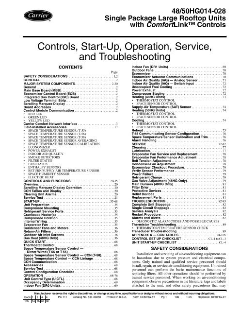
48/50HG014-028<br />
Single Package Large Rooftop Units<br />
with ComfortLink <strong>Controls</strong><br />
Indoor Fan (DR1 Units) ...................................69<br />
Outdoor Fans ............................................70<br />
Economizer ..............................................70<br />
Economizer Actuator Communications...................70<br />
Indoor Air Quality (IAQ) — Analog Sensor................71<br />
Indoor Air Quality (IAQ) — Switch Input ..................72<br />
Unoccupied Free Cooling ................................72<br />
Power Exhaust ...........................................72<br />
Compressor Staging .....................................72<br />
Heating (48HG Units) .....................................73<br />
THERMOSTAT CONTROL<br />
SPACE SENSOR CONTROL<br />
Supply-Air Temperature (SAT) Sensor ....................74<br />
Heating (50HG Units) .....................................74<br />
THERMOSTAT CONTROL<br />
SPACE SENSOR CONTROL<br />
Cooling...................................................74<br />
THERMOSTAT CONTROL<br />
SPACE SENSOR CONTROL<br />
Reheat ...................................................75<br />
T-58 Communicating Sensor Configuration...............76<br />
Space Temperature Sensor Calibration <strong>and</strong> Trim .........76<br />
Alarm H<strong>and</strong>ling...........................................76<br />
SERVICE .............................................. 77-82<br />
Cleaning .................................................77<br />
Lubrication...............................................77<br />
Evaporator Fan <strong>Service</strong> <strong>and</strong> Replacement................78<br />
Evaporator Fan Performance Adjustment ................78<br />
Belt Tension Adjustment .................................78<br />
Condenser-Fan Adjustment ..............................78<br />
Economizer Checkout Procedure.........................79<br />
Verify Sensor Performance ...............................79<br />
Power Failure.............................................79<br />
Refrigerant Charge .......................................79<br />
Gas Valve Adjustment (48HG Only).......................79<br />
Main Burners (48HG Only)................................81<br />
Filter Drier................................................81<br />
Protective Devices .......................................81<br />
Relief Devices ............................................81<br />
Replacement Parts .......................................81<br />
TROUBLESHOOTING.................................. 82-93<br />
Complete Unit Stoppage .................................82<br />
Single Circuit Stoppage ..................................82<br />
<strong>Service</strong> Analysis .........................................82<br />
Restart Procedure........................................82<br />
Alarms <strong>and</strong> Alerts ........................................82<br />
DIAGNOSTIC ALARM CODES AND POSSIBLE CAUSES<br />
Thermistor <strong>Troubleshooting</strong>..............................89<br />
THERMISTOR/TEMPERATURE SENSOR CHECK<br />
Transducer <strong>Troubleshooting</strong> .............................89<br />
APPENDIX A — CCN TABLES ........................ 94-105<br />
CONTROL SET UP CHECKLIST .................CL-1toCL-3<br />
UNIT START-UP CHECKLIST ...........................CL-4<br />
SAFETY CONSIDERATIONS<br />
Installation <strong>and</strong> servicing of air-conditioning equipment can<br />
be hazardous due to system pressure <strong>and</strong> electrical components.<br />
Only trained <strong>and</strong> qualified service personnel should<br />
install, repair, or service air-conditioning equipment. Untrained<br />
personnel can perform the basic maintenance functions of<br />
replacing filters. All other operations should be performed by<br />
trained service personnel. When working on air-conditioning<br />
equipment, observe precautions in the literature, tags <strong>and</strong> labels<br />
attached to the unit, <strong>and</strong> other safety precautions that may<br />
Manufacturer reserves the right to discontinue, or change at any time, specifications or designs without notice <strong>and</strong> without incurring obligations.<br />
Book 1 1 4 4 PC 111 Catalog No. 534-80250 Printed in U.S.A. Form 48/50HG-5T Pg 1 106 1-05 Replaces: 48/50HG-3T<br />
Tab 1a 1b 6a 6b
apply. Follow all safety codes. Wear safety glasses <strong>and</strong> work<br />
gloves. Use quenching cloth for unbrazing operations. Have<br />
fire extinguishers available for all brazing operations.<br />
GENERAL<br />
This publication contains <strong>Start</strong>-<strong>Up</strong>, <strong>Controls</strong>, <strong>Operation</strong>,<br />
<strong>and</strong> <strong>Troubleshooting</strong> information for the 48/50HG rooftop<br />
units. See Table 1. These units are equipped with<br />
ComfortLink controls.<br />
Table 1 — Unit Sizes (48/50HG)<br />
UNIT NOMINAL TONS<br />
48/50HG014 12 1/ 2<br />
48/50HG016 15<br />
48/50HG020 18<br />
48/50HG024 20<br />
48/50HG028 25<br />
Currently, 48/50HG units are being produced in two separate<br />
factories. Depending on where the unit is made, small differences<br />
are present in the units. This guide covers units made<br />
in both factories. The units are differentiated by the design revision<br />
number in the model number nomenclature (position 13).<br />
There are design revision 0 <strong>and</strong> design revision 1 HG units currently<br />
being produced. Design revision 0 units will be referred<br />
as DR0 <strong>and</strong> design revision 1 units will be referred to as DR1<br />
in this literature. Table 2 lists the major differences between<br />
DR0 <strong>and</strong> DR1 units.<br />
Table 2 — Design Revision Differences<br />
ITEM DR0 UNIT DR1 UNIT<br />
Number of Terminal<br />
Strips<br />
4or5 1or2<br />
SAT Location Underneath gas section Blower side plate<br />
Economizer section Condenser support<br />
OAT Location<br />
bracket (inboard condenser,<br />
return bend<br />
side)<br />
SAT<strong>and</strong>OATSensors5K Type 10K Type<br />
Fan Power Relay YES NO<br />
Economizer Power<br />
Relay<br />
Only with no reheat NO<br />
575 VUnit Step-down transformers All components 575 V<br />
Power Exhaust Separate fuses No additional fuses<br />
Fan Status Wires Accessory St<strong>and</strong>ard<br />
Smoke Detectors System Sensor Type Tel Aire Type<br />
Condensing<br />
Thermistor<br />
Located on hairpins Located on return bends<br />
Outdoor Fan Wiring Located far side of unit Located near side of unit<br />
MAJOR SYSTEM COMPONENTS<br />
General — The 48/50HG single package rooftop units with<br />
electric cooling <strong>and</strong> gas heating (48HG units) or electric<br />
cooling <strong>and</strong> electric heating (50HG units) contain the<br />
ComfortLink electronic control system that monitors all operations<br />
of the rooftop. The control system is composed of several<br />
components as listed in sections below. See Fig. 1A-3B for the<br />
control <strong>and</strong> power schematics. Figures 4A <strong>and</strong> 4B shows the<br />
layout of the control box, unit, <strong>and</strong> thermistor <strong>and</strong> transducer<br />
locations.<br />
Main Base Board (MBB) — See Fig. 5 <strong>and</strong> Table 3.<br />
The MBB is the center of the ComfortLink control system. It<br />
contains the major portion of the operating software <strong>and</strong> controls<br />
the operation of the unit. The MBB continuously monitors<br />
input/output channel information received from its inputs <strong>and</strong><br />
from the Economizer Control Board (ECB). The MBB receives<br />
inputs from thermistors <strong>and</strong> transducers. The MBB also<br />
receives the Current Sensor inputs for compressors A1, B1 <strong>and</strong><br />
C1 <strong>and</strong> other discrete or digital inputs. The MBB reads space<br />
temperature (SPT) from either a T-55, T-56 or T-58 device <strong>and</strong><br />
space temperature offset (SPTO) from a T-56 device. See<br />
Field-Installed Accessories section on page 17. The MBB controls<br />
11 relays.<br />
2<br />
Economizer Control Board (ECB) — The ECB<br />
(part no. 50TG500596) controls the economizer actuator. See<br />
Fig. 6 <strong>and</strong> Table 4. The control signal from the ECB uses either<br />
the Belimo communication protocol or a 4 to 20 mA output<br />
signal as defined by the configuration ECTL. The analog signal<br />
is only available on unit software 3.1 or later. The ECB has inputs<br />
for Indoor Air Quality (IAQ), Outdoor Air Quality<br />
(OAQ), <strong>and</strong> enthalpy. It also controls two power exhaust motors<br />
(PE1 <strong>and</strong> PE2).<br />
By digitally communicating with the ECB, the economizer<br />
actuator is able to provide the damper position <strong>and</strong> diagnostic<br />
information to the ComfortLink controller. The damper position<br />
is displayed as EC.AP under Outputs/Econ on the Scrolling<br />
Marquee. Diagnostic information is displayed via Alert<br />
T414. More information about these alarms is contained in the<br />
Alarms <strong>and</strong> Alerts section.<br />
On the ECB, RLY 6 can either provide power to the economizer<br />
actuator or reheat valve for Circuit B. For DR0 units, the<br />
configuration Economizer Power Relay Installed (EPR), located<br />
under Unit on the Scrolling Marquee, must be set to YES.<br />
For DR1 units this configuration must be set to NO. For DR0<br />
units, RLY 6 will control economizer actuator power unless reheat<br />
is installed. For DR1 units, RLY 6 will only control reheat<br />
as needed.<br />
Integrated Gas Control (IGC) Board — The IGC<br />
is provided on gas heat units. See Table 5. The IGC controls the<br />
direct spark ignition system <strong>and</strong> monitors the rollout switch,<br />
limit switch, <strong>and</strong> induced-draft motor Hall Effect switch. The<br />
IGC is equipped with an LED (light-emitting diode) for diagnostics.<br />
See the <strong>Troubleshooting</strong> section for more information.<br />
Low Voltage Terminal Strip — This circuit board<br />
provides a connection point between the major control boards<br />
<strong>and</strong> a majority of the field-installed accessories. See Fig. 7 <strong>and</strong><br />
Tables 6A <strong>and</strong> 6B. The circuit breakers for the low voltage<br />
control transformers, interface connection for the Carrier Comfort<br />
Network (CCN) communication, <strong>and</strong> interface connection<br />
for the Local Equipment Network (LEN) communications are<br />
also located on the low voltage terminal strip.<br />
Scrolling Marquee Display — This device is the keypad<br />
interface used to access rooftop information, read sensor<br />
values, <strong>and</strong> test the unit. See Fig. 8. The marquee display is a<br />
4-key, 4-character, 16-segment LED (light-emitting diode)<br />
display. Eleven mode LEDs are located on the display as well<br />
as an Alarm Status LED. See Scrolling Marquee Display <strong>Operation</strong><br />
section on page 20 for further details.<br />
Board Addresses — The Main Base Board (MBB) has<br />
a 3-position instance jumper that is set at the factory to “1.” Do<br />
not change this setting. The ECB has a 4-position DIP switch.<br />
Each DIP switch is set to “0” at the factory. Do not change this<br />
setting.<br />
Control Module Communication<br />
RED LED — Proper operation of the control boards can be<br />
visually checked by looking at the red status LEDs. When operating<br />
correctly, the red status LEDs should blink in unison at<br />
a rate of once every 2 seconds. If the red LEDs are not blinking<br />
in unison, verify that correct power is being supplied to all<br />
modules. Also, be sure that the Main Base Board is supplied<br />
with the current software. If necessary, reload current software.<br />
If the problem still persists, replace the MBB. A board LED<br />
that is lit continuously or blinking at a rate of once per second<br />
or faster indicates that the board should be replaced.<br />
GREEN LED — The MBB has one green LED. The Local<br />
Equipment Network (LEN) LED should always be blinking<br />
whenever power is on. All other boards have a LEN LED that<br />
will blink whenever power is on. If LEN LED is not blinking,<br />
check LEN connections for potential communication errors (J3<br />
<strong>and</strong> J4 connectors). Communication between modules is<br />
accomplished by a 3-wire sensor bus. These 3 wires run in
parallel from module to module. The J4 connector on the MBB<br />
provides both power <strong>and</strong> communication directly to the marquee<br />
display.<br />
YELLOW LED — The MBB has one yellow LED. The<br />
Carrier Comfort Network (CCN) LED will blink during times<br />
of network communication.<br />
Carrier Comfort Network Interface — The 48/<br />
50HG units can be connected to the CCN if desired. The communication<br />
bus wiring is a shielded, 3-conductor cable with<br />
drain wire <strong>and</strong> is field supplied <strong>and</strong> installed. See Table 7 for<br />
wiring information. The system elements are connected to the<br />
communication bus in a daisy chain arrangement. The positive<br />
pin of each system element communication connector must be<br />
wired to the positive pins of the system elements on either side<br />
of it. This is also required for the negative <strong>and</strong> signal ground<br />
pins of each system element. Wiring connections for CCN<br />
should be made at TB2. See Fig. 1A-2B. Consult the CCN<br />
Contractor's Manual for further information.<br />
NOTE: Conductors <strong>and</strong> drain wire must be 20 AWG (American<br />
Wire Gage) minimum str<strong>and</strong>ed, tinned copper. Individual<br />
conductors must be insulated with PVC, PVC/nylon, vinyl,<br />
Teflon, or polyethylene. An aluminum/polyester 100% foil<br />
shield <strong>and</strong> an outer jacket of PVC, PVC/nylon, chrome vinyl,<br />
or Teflon with a minimum operating temperature range of<br />
–20 C to 60 C is required. See Table 7.<br />
It is important when connecting to a CCN communication<br />
bus that a color-coding scheme be used for the entire network<br />
to simplify the installation. It is recommended that red be used<br />
for the signal positive, black for the signal negative <strong>and</strong> white<br />
3<br />
for the signal ground. Use a similar scheme for cables containing<br />
different colored wires.<br />
At each system element, the shields of its communication bus<br />
cables must be tied together. The shield screw on TB2 can be<br />
used to tie the cables together. If the communication bus is<br />
entirely within one building, the resulting continuous shield must<br />
be connected to a ground at one point only. The shield screw on<br />
TB2 is not acceptable for grounding. If the communication bus<br />
cable exits from one building <strong>and</strong> enters another, the shields<br />
must be connected to grounds at the lightning suppressor in each<br />
building where the cable enters or exits the building (one point<br />
per building only). To connect the unit to the network:<br />
1. Turn off power to the control box.<br />
2. Cut the CCN wire <strong>and</strong> strip the ends of the red (+), white<br />
(ground), <strong>and</strong> black (–) conductors. (Substitute appropriate<br />
colors for different colored cables.)<br />
3. Connect the red wire to (+) terminal on TB2 of the plug,<br />
the white wire to COM terminal, <strong>and</strong> the black wire to the<br />
(–) terminal.<br />
4. The RJ14 CCN connector on TB2 can also be used, but is<br />
only intended for temporary connection (for example, a<br />
laptop computer running <strong>Service</strong> Tool).<br />
5. Restore power to unit.<br />
IMPORTANT: A shorted CCN bus cable will prevent some<br />
routines from running <strong>and</strong> may prevent the unit from starting.<br />
If abnormal conditions occur, unplug the connector. If conditions<br />
return to normal, check the CCN connector <strong>and</strong> cable.<br />
Run new cable if necessary. A short in one section of the bus<br />
can cause problems with all system elements on the bus.
NOTES:<br />
1. Use TB5-5 <strong>and</strong> TB5-6 for remote occupancy switch.<br />
Remember to configure software; see <strong>Controls</strong> <strong>and</strong><br />
<strong>Troubleshooting</strong> Guide.<br />
2. See legend on page 10.<br />
4<br />
Fig. 1A — Low Voltage Control Schematic — 48HG Units (DR0)
NOTES:<br />
1. Use TB5-5 <strong>and</strong> TB5-6 for remote occupancy switch.<br />
Remember to configure software; see <strong>Controls</strong> <strong>and</strong><br />
<strong>Troubleshooting</strong> Guide.<br />
2. See legend on page 10.<br />
5<br />
Fig. 1B — Low Voltage Control Schematic — 48HG Units (DR1)
NOTES:<br />
1. Use TB5-5 <strong>and</strong> TB5-6 for remote occupancy switch.<br />
Remember to configure software; see <strong>Controls</strong> <strong>and</strong><br />
<strong>Troubleshooting</strong> Guide.<br />
2. See legend on page 10.<br />
6<br />
Fig. 2A — Low Voltage Control Schematic — 50HG Units (DR0)
NOTES:<br />
1. Use TB5-5 <strong>and</strong> TB5-6 for remote occupancy switch.<br />
Remember to configure software; see <strong>Controls</strong> <strong>and</strong><br />
<strong>Troubleshooting</strong> Guide.<br />
2. See legend on page 10.<br />
7<br />
Fig. 2B — Low Voltage Control Schematic — 50HG Units (DR1)
NOTE: See legend on page 10.<br />
Fig. 3A — Typical Power Schematic (DR0)<br />
8
NOTE: See legend on page 10.<br />
Fig. 3B — Typical Power Schematic (DR1)<br />
9
10<br />
LEGEND FOR FIG. 1A TO 4B<br />
NOTES:<br />
1. Factory wiring is in accordance with the National Electrical<br />
Codes. Any field modifications or additions must be in compliance<br />
with all applicable codes.<br />
2. Use 75° C min wire for field power supply. Use copper wires<br />
for all units.<br />
3. All circuit breakers Must Trip Amps are equal to or less than<br />
156% RLA.<br />
4. Compressor <strong>and</strong> fan motors are thermally protected. Threephase<br />
motors protected against primary single-phase<br />
conditions.<br />
5. Red jumper wire must be added between R <strong>and</strong> W1 for<br />
Space Temperature mode <strong>and</strong> temporarily during <strong>Service</strong><br />
Test mode when the heaters need to operate.<br />
THERMOSTAT/IGC MARKINGS<br />
BM — Blower Motor<br />
C — Common<br />
CM — Inducer Motor<br />
CS — Centrifugal Switch<br />
G — Fan<br />
IFO — Indoor Fan On<br />
L1 — Line 1<br />
R — Thermostat Power<br />
RT — Power Supply<br />
SS — Speed Sensor<br />
W — Thermostat Heat<br />
W1 — 1st Stage of Heating<br />
W2 — 2nd Stage of Heating<br />
X — Alarm Output<br />
Y1 — 1st Stage of Cooling<br />
Y2 — 2nd Stage of Cooling<br />
TB — Terminal Block<br />
TRAN — Transformer<br />
T-55 — Room Temp Device<br />
T-56 — Room Temp Device with Set<br />
Point Adjustment<br />
Terminal Block<br />
Terminal (Unmarked)<br />
Terminal (Marked)<br />
Splice<br />
Factory Wiring<br />
Field Wiring<br />
To indicate common potential<br />
only, not to represent wiring.<br />
IDM — Induced-Draft Motor<br />
IFC — Indoor-Fan Contactor<br />
IFCB — Indoor-Fan Circuit Breaker<br />
IFM — Indoor-Fan Motor<br />
IGC — Integrated Gas Controller<br />
LEN — Local Equipment Network<br />
LS — Limit Switch<br />
MBB — Main Base Board<br />
OAQ — Outdoor-Air Quality<br />
OAT — Outdoor-Air Temperature<br />
OFC — Outdoor-Fan Contactor<br />
OFM — Outdoor-Fan Motor<br />
PEC — Power Exhaust Contactor<br />
PEM — Power Exhaust Motor<br />
PL — Plug<br />
QC — Quick Connect<br />
QT — Quadruple Terminal<br />
RS — Rollout Switch<br />
SAT — Supply-Air Temperature<br />
SCT — Saturated Condensing Temp<br />
To indicate FIOP or Accessory<br />
SSP — Saturated Suction Pressure<br />
---.A — Circuit A<br />
AUX — Auxiliary Contact<br />
---.B — Circuit B<br />
---.C — Circuit C<br />
C — Compressor, Contactor<br />
CAP — Capacitor<br />
CB — Circuit Breaker<br />
CCN — Carrier Comfort Network<br />
CCH — Crankcase Heater<br />
COMP — Compressor<br />
CS — Current Sensor<br />
EC — Enthalpy Control<br />
ECB — Economizer Control Board<br />
FIOP — Factory-Installed Option<br />
FS — Flame Sensor<br />
FU — Fuse<br />
GND — Ground<br />
GV — Gas Valve<br />
HPS — High-Pressure Switch<br />
I — Ignitor<br />
IAQ — Indoor-Air Quality<br />
Fig. 4A — Typical Component Arrangement (DR0)
11<br />
Fig. 4B — Typical Component Arrangement (DR1)<br />
NOTE: See legend on page 10.
J1 J2<br />
J4<br />
J6<br />
RED LED - STATUS GREEN LED -<br />
LEN (LOCAL EQUIPMENT NETWORK)<br />
J3<br />
J5<br />
CEPL130346-01<br />
LEN<br />
CCN<br />
STATUS<br />
J7 J8 J9<br />
Fig. 5 — Main Base Board<br />
12<br />
YELLOW LED -<br />
CCN (CARRIER COMFORT NETWORK)<br />
INSTANCE JUMPER<br />
J10
Table 3 — MBB Connections<br />
DISPLAY NAME<br />
INPUTS<br />
POINT DESCRIPTION SENSOR LOCATION TYPE OF I/O<br />
CONNECTION<br />
PIN NUMBER<br />
Input power from TRAN1 control box 24 VAC J1, 1-3<br />
Indoor fan output feedback (IGC) gas section switch input J6, 4<br />
FDWN Fire shutdown switch supply/return/space switch input J6, 5-6<br />
G Thermostat G (Fan) space switch input J7, 2<br />
W2 Thermostat W2 (2nd Stage Heat) space switch input J7, 4<br />
W1 Thermostat W1 (1st Stage Heat) space switch input J7, 6<br />
Y2 Thermostat Y2 (2nd Stage Cool) space switch input J7, 8<br />
Y1 Thermostat Y1 (1st Stage Cool) space switch input J7, 10<br />
SPT Space temperature (T55/56) space 10k thermistor J8, 1-2<br />
SPTO or RAT<br />
Space temperature offset (T56) or<br />
Return air temperature<br />
space or return 10k thermistor J8, 2-3<br />
OAT Outdoor air temperature<br />
economizer section (DR0)<br />
outdoor coil support (DR1)<br />
5k thermistor (DR0)<br />
J8, 5-6<br />
10k thermistor (DR1)<br />
SAT Supply air temperature<br />
heat section (DR0)<br />
indoor fan housing, or supply<br />
duct (DR1)<br />
5k thermistor (DR0)<br />
J8, 7-8<br />
10k thermistor (DR1)<br />
SCT.A Saturated condenser temperature, circuit A<br />
A condenser hairpin (DR0)<br />
A condenser return bend (DR1)<br />
5k thermistor J8, 9-10<br />
SCT.B Saturated condenser temperature, circuit B<br />
B condenser hairpin (DR0)<br />
B condenser return bend (DR1)<br />
5k thermistor J8, 11-12<br />
SCT.C Saturated condenser temperature, circuit C<br />
C condenser hairpin (DR0)<br />
C condenser return bend (DR1)<br />
5k thermistor J8, 13-14<br />
FAN.S Fan status switch indoor fan section switch input J8, 15-16<br />
SSP.A Suction pressure, circuit A compressor A suction analog input J8, 18-20<br />
SSP.B Suction pressure, circuit B compressor B suction analog input J8, 21-23<br />
SSP.C Suction pressure, circuit C compressor C suction analog input J8, 24-26<br />
FIL.S Filter status switch indoor fan section switch input J9, 2-3<br />
CS.A1 Compressor A1 Feedback control box digital input J9, 4-6<br />
CS.B1 Compressor B1 Feedback control box digital input J9, 7-9<br />
CS.C1<br />
OUTPUTS<br />
Compressor C1 Feedback control box digital input J9, 10-12<br />
Output power to ECB 24 VAC J2, 1-2<br />
Output power to Marquee Display 24 VAC J4, 5-6<br />
IDFP Indoor Fan Power (DR0 only) relay J10, 3<br />
C1 Compressor C1 relay J10, 6<br />
B1 Compressor B1 relay J10, 9<br />
A1 Compressor A1 relay J10, 11<br />
OFC.3 Outdoor fan 3 relay J10, 13<br />
OFC.1 Outdoor fan 1 relay J10, 16<br />
OFC.2 Outdoor fan 2 relay J10, 19<br />
IDF Indoor fan relay J10, 21<br />
ALRM Alarm relay J10, 23<br />
HTR.1 Heat stage 1 relay J10, 25<br />
HTR.2<br />
COMMUNICATION<br />
Heat stage 2 relay J10, 27<br />
Local Equipment Network (LEN) communication J5, 1-3<br />
Carrier Comfort Network (CCN) communication J5, 5-7<br />
Network device power 24 VAC J5, 9-10<br />
13
Fig. 6 — Economizer Control Board<br />
Table 4 — ECB Connections<br />
DISPLAY NAME<br />
INPUTS<br />
POINT DESCRIPTION SENSOR LOCATION TYPE OF I/O<br />
CONNECTION<br />
PIN NUMBER<br />
RM.OC<br />
Input power from MBB<br />
Remote occupancy switch<br />
control box field<br />
installed<br />
24 VAC<br />
switch input<br />
J1, 1-2<br />
J4, 2<br />
ENTH or<br />
IAQ.S<br />
Outdoor enthalpy switch, or<br />
Indoor air quality switch<br />
economizer, or<br />
return/space<br />
switch input J4, 4<br />
IAQ Indoor air quality sensor return/space 4-20 mA J5, 2-3<br />
OAQ or RHS<br />
OUTPUTS<br />
Outdoor air quality sensor, or<br />
Relative humidity sensor<br />
field installed 4-20 mA J5, 3-4<br />
— Output power to enthalpy switch 24 VAC J4, 3<br />
— Output power to economizer motor 24 VAC J7, 2<br />
PE.1 Power exhaust relay 1 relay J8, 3<br />
PE.2 Power exhaust relay 2 relay J8, 6<br />
RHT.A Reheat circuit A Output relay J8, 9<br />
RHT.B<br />
ECPR<br />
Reheat circuit B Output (Reheat units or DR1)<br />
Economizer Power (DR0 without reheat)<br />
relay J8, 18<br />
EC.CP or EC.AP<br />
COMMUNICATION<br />
Economizer actuator (analog, digital) 4-20 mA J9, 1<br />
— Local Equipment Network (LEN) communication J2, 1-3<br />
EC.CP <strong>and</strong> EC.AP Economizer actuator (digital control) communication J7, 1 & 3<br />
14
Table 5 — IGC Connections<br />
TERMINAL LABEL<br />
INPUTS<br />
POINT DESCRIPTION SENSOR LOCATION TYPE OF I/O<br />
CONNECTION<br />
PIN NUMBER<br />
RT, C Input power from TRAN 2 control box 24 VAC<br />
SS Speed sensor gas section analog input J1, 1-3<br />
FS, T1 Flame sensor gas section switch input<br />
W Heat stage 1 MBB 24 VAC J2, 2<br />
RS Rollout switch gas section switch input J2, 5-6<br />
LS Limit switch gas section switch input J2, 7-8<br />
CS Centrifugal switch (not used) switch input J2, 9-10<br />
L1<br />
OUTPUTS<br />
Line power for induced draft combustion motor - line power L1<br />
CM Induced draft combustion motor gas section relay CM<br />
IFO Indoor fan MBB relay J2, 1<br />
GV Gas valve (heat stage 1) gas section relay J2, 11-12<br />
Table 6A — Field Connections for Low-Voltage Terminal Strip (TB2 to TB5 for DR0 Units)<br />
TERMINAL LABEL DISPLAY NAME POINT DESCRIPTION SENSOR LOCATION TYPE OF I/O<br />
LEN (TB2) Local Equipment Network (LEN) communication<br />
CCN (TB2) Carrier Comfort Network (CCN) communication<br />
5-6 (TB3) FDWN Fire shutdown switch supply/return/space switch input<br />
7-8 (TB3) SPT Space temperature (T55/56) space 10k thermistor<br />
8- 9 (TB3) SPTO or RAT<br />
Space temperature offset (T56) or<br />
Return air temperature<br />
space or return 10k thermistor<br />
11-12 (TB3) FAN.S Fan Status blower section 24 VAC input<br />
R (TB4) 24 VAC power 24 VAC output<br />
Y1 (TB4) Y1 Thermostat Y1 (1st stage cool) space 24 VAC input<br />
Y2 (TB4) Y2 Thermostat Y2 (2nd stage cool) space 24 VAC input<br />
W1 (TB4) W1 Thermostat W1 (1st stage heat) space 24 VAC input<br />
W2 (TB4) W2 Thermostat W2 (2nd stage heat) space 24 VAC input<br />
G (TB4) G Thermostat G (Fan) space 24 VAC input<br />
C (TB4) 24 VAC common 24 VAC output<br />
X (TB4) ALRM Alarm output (normally open) 24 VAC output<br />
2 (TB5) IAQ Indoor air quality sensor return/space 4-20 mA input<br />
3 (TB5) Indoor & outdoor air quality common 4-20 mA input<br />
4 (TB5) OAQ or RHS<br />
Outdoor air quality sensor, or<br />
Relative humidity sensor<br />
field installed 4-20 mA input<br />
5(TB5) RM.OCorHUM<br />
Remote occupancy switch, or<br />
Humidistat Input<br />
field installed 24 VAC input<br />
6 (TB5) 24V output for enthalpy switch economizer 24 VAC input<br />
7(TB5)<br />
ENTH or<br />
IAQ.S<br />
Outdoor enthalpy switch, or<br />
Indoor air quality switch<br />
economizer, or<br />
return/space<br />
24 VAC input<br />
8(TB5)<br />
EC.CP or EC.AP<br />
EC.CP<br />
Economizer actuator (digital control)<br />
Economizer actuator (analog control)<br />
economizer 2-10 VDC output<br />
9(TB5)<br />
EC.CP<br />
-<br />
Economizer actuator (digital control)<br />
Economizer actuator (analog control)<br />
economizer<br />
communication<br />
2-10 VDC output<br />
10 (TB5) Economizer signal common economizer VDC<br />
15
17<br />
J10<br />
J11<br />
SEPARATION OF CIRCUITS TO EACH 24V TRANSFORMER MUST BE MAINTAINED<br />
1 2 3 4 5 6 7 8 9 10 R Y1 Y2 W1 W2 G C X 1 2 1 2 3 1 2<br />
Table 6B — Field Connections for Low-Voltage Terminal Strip (TB2 for DR1 Units)<br />
TERMINAL LABEL DISPLAY NAME POINT DESCRIPTION SENSOR LOCATION TYPE OF I/O<br />
CONNECTION<br />
PIN NUMBER<br />
1<br />
(not used)<br />
24 VAC output J10, 17<br />
2 IAQ<br />
Indoor air quality sensor return/space 4-20 mA input J10, 16<br />
3 Indoor & outdoor air quality common 4-20 mA input J10, 15<br />
4 OAQ or RHS<br />
Outdoor air quality sensor, or<br />
Relative humidity sensor<br />
field installed 4-20 mA input J10, 14<br />
5 RM.OC or HUM<br />
Remote occupancy switch, or<br />
Humidistat Input<br />
field installed 24 VAC input J10, 13<br />
6 Outdoor enthalpy switch power economizer 24 VAC input J10, 11-12<br />
7 ENTH or IAQ.S<br />
Outdoor enthalpy switch, or<br />
Indoor air quality switch<br />
economizer, or<br />
return/space<br />
24 VAC input J10, 9-10<br />
EC.CP or EC.AP Economizer actuator (digital control)<br />
8<br />
EC.CP<br />
Economizer actuator (analog<br />
control)<br />
economizer 2-10 VDC output J10, 6-8<br />
9 Economizer signal common economizer VDC J10, 3-5<br />
EC.CP<br />
Economizer actuator (digital control)<br />
communication<br />
10<br />
-<br />
Economizer actuator (analog<br />
control)<br />
economizer<br />
2-10 VDC output J10, 1-2<br />
R 24 VAC power 24 VAC output J11, 11-14<br />
Y1 Y1 Thermostat Y1 (1st stage cool) space 24 VAC input J11,10<br />
Y2 Y2 Thermostat Y2 (2nd stage cool) space 24 VAC input J11, 9<br />
W1 W1 Thermostat W1 (1st stage heat) space 24 VAC input J11, 7-8<br />
W2 W2 Thermostat W2 (2nd stage heat) space 24 VAC input J11, 6<br />
G G Thermostat G (Fan) space 24 VAC input J11, 5<br />
C 24 VAC common 24 VAC output J11, 2-4<br />
X ALRM Alarm output (normally open) 24 VAC output J11, 1<br />
FIRE SHUTDOWN 1-2 FDWN Fire shutdown switch supply/return/space switch input J12, 6-7<br />
T55 1-2 SPT Space temperature (T55/56) space 10k thermistor J12, 4-5<br />
T55 2-3 SPTO or RAT<br />
Space temperature offset (T56) or<br />
Return air temperature<br />
space or return 10k thermistor J12, 3-4<br />
FAN STATUS 1-2 - (not used) - - J12, 1-2<br />
LEN Local Equipment Network (LEN) communication J13, 6-8, 4-5<br />
CCN Carrier Comfort Network (CCN) communication J13, 1-3, 4-5<br />
Table 7 — CCN Communication Bus Wiring<br />
MANUFACTURER PART NO.<br />
Alpha 2413 or 5463<br />
Belden 8772<br />
Carol C2528<br />
West Penn 302<br />
14<br />
16<br />
7<br />
RUN TEST<br />
FIRE SHUTDOWN<br />
Fig. 7 — Low-Voltage Terminal Strip<br />
MODE<br />
Run Status<br />
<strong>Service</strong> Test<br />
Temperature<br />
Pressures<br />
Setpoints<br />
Inputs<br />
Outputs<br />
Configuration<br />
Time Clock<br />
Operating Modes<br />
Alarms<br />
7<br />
J12<br />
T55<br />
Alarm Status<br />
ESCAPE<br />
FAN STATUS<br />
J13 8<br />
(+)<br />
ENTER<br />
(COM) (-) SHIELD<br />
CCN<br />
LEN CCN<br />
Fig. 8 — Scrolling ComfortLink Display<br />
48HG500382
Field-Installed Accessories<br />
SPACE TEMPERATURE SENSOR (T-55) — The T-55<br />
Space Temperature Sensor (part no. 33ZCT55SPT) is a fieldinstalled<br />
accessory. The sensor is installed on a building interior<br />
wall to measure room air temperature. The T-55 sensor also<br />
includes an override button on the front cover to permit occupants<br />
to override the Unoccupied Schedule (if programmed).<br />
The jumper wire in the installer’s packet or on the control box<br />
cover must be connected between R <strong>and</strong> W1 when using a<br />
T-55 device. See Fig. 9-11.<br />
SPACE TEMPERATURE SENSOR (T-56) — The T-56<br />
Space Temperature Sensor (part no. 33ZCT56SPT) is a fieldinstalled<br />
accessory. This sensor includes a sliding scale on the<br />
front cover that permits an occupant to adjust the space temperature<br />
set point remotely. The T-56 sensor also includes an override<br />
button on the front cover to allow occupants to override<br />
the unoccupied schedule (if programmed). The jumper wire in<br />
the installer’s packet must be connected between R <strong>and</strong> W1<br />
when using a T-56 device. See Fig. 9, 10, <strong>and</strong> 12.<br />
SPACE TEMPERATURE SENSOR (T-58) — The T-58<br />
Space Temperature Sensor (part no. 33ZCT58SPT) is a fieldinstalled<br />
accessory. The T-58 sensor communicates with the<br />
ComfortLink controller, providing space temperature, heating<br />
<strong>and</strong> cooling set points, <strong>and</strong> mode operation information.<br />
The jumper wire in the installer’s packet or on the control box<br />
cover must be connected between R <strong>and</strong> W1 when using a<br />
T-58 device. See Fig. 13.<br />
Refer to the T-58 installation instructions for information on<br />
installing <strong>and</strong> configuring the T-58 sensor.<br />
Each T-58 sensor must have a unique address on the CCN.<br />
Each T-58 sensor must also be configured with the address of<br />
the unit control it is communicating to.<br />
Cool<br />
Warm<br />
Fig. 9 — Space Temperature Sensor<br />
(P/N 33ZCT56SPT Shown)<br />
17<br />
NOTE: Dimensions are in inches.<br />
Fig. 10 — Space Temperature Sensor Mounting<br />
1<br />
SW1<br />
2 3 4 5 6<br />
SEN<br />
RED(+)<br />
WHT(GND)<br />
BLK(-)<br />
BLK (GND)<br />
RED (SPT)<br />
CCN COM<br />
SENSOR WIRING<br />
Fig. 11 — T-55 Space Temperature Sensor Wiring<br />
(P/N 33ZCT55SPT)
1<br />
SW1<br />
2 3 4 5 6<br />
SEN SET<br />
RED(+)<br />
WHT(GND)<br />
BLK(-)<br />
WHT<br />
(T56)<br />
BLK (GND)<br />
RED (SPT)<br />
Cool Warm<br />
CCN COM<br />
SENSOR WIRING<br />
JUMPER<br />
TERMINALS<br />
AS SHOWN<br />
Fig. 12 — T-56 Space Temperature Sensor Wiring<br />
(P/N 33ZCT56SPT)<br />
SPACE TEMPERATURE SENSOR AVERAGING — See<br />
Fig. 14 for space temperature averaging with T-55 sensors only.<br />
If the use of one T-56 sensor is required, refer to Fig. 15.<br />
SPACE TEMPERATURE SENSOR CALIBRATION — The<br />
temperature reading of the space temperature sensors can be<br />
calibrated. Refer to the Space Temperature Sensor Calibration<br />
<strong>and</strong> Trim section on page 76 for more information.<br />
ECONOMIZER — The economizer accessories (part<br />
no. CRECOMZR009E01) for size 014-024 units <strong>and</strong> part<br />
no. CRECOMZR011E01 for size 028 units) are field-installed<br />
accessories. When installing this accessory, the unit must be<br />
configured for economizer installation by setting EC.EQ to<br />
YES. The default settings for the other economizer configurations<br />
should be satisfactory. If they need to be changed, additional<br />
information about these configuration settings can be<br />
found in the Economizer section.<br />
POWER EXHAUST — The power exhaust accessories<br />
(part no. CRPWREXH018B00, CRPWREXH019B00,<br />
CRPWREXH020B00) are field-installed accessories for<br />
power exhaust for different voltages. When installing this<br />
accessory, the unit must be configured for power exhaust<br />
installation by setting PE.EN to ENBL. The default settings for<br />
the other power exhaust configurations should be satisfactory.<br />
If they need to be changed, additional information about these<br />
configurations can be found in the Power Exhaust section.<br />
INDOOR AIR QUALITY — The indoor air quality (IAQ)<br />
accessory (part no. CRCBDIOX001B00) is a field-installed accessory.<br />
This sensor measures CO 2 concentrations in the unit<br />
return. The defaults for IAQ configurations should be satisfactory;<br />
however, if they are not, additional information about these configurations<br />
can be found in the Indoor Air Quality Analog Sensor<br />
<strong>and</strong> Switch Input section.<br />
SMOKE DETECTORS — The smoke detectors are fieldinstalled<br />
accessories. These detectors can detect smoke in<br />
either the return duct (part no. CRSMKDET001D00) or supply<br />
18<br />
T-58 SENSOR<br />
VAC<br />
COM<br />
CCN-<br />
GND<br />
CCN+<br />
24 VAC<br />
BLACK (-)<br />
WHITE (GND)<br />
RED (+)<br />
BLACK (-)<br />
WHITE (GND)<br />
RED (+)<br />
CCN —<br />
LEGEND<br />
Carrier Comfort Network<br />
Fig. 13 — T-58 Communicating Space<br />
Temperature Sensor Wiring<br />
CCN<br />
COM<br />
CCN<br />
COM<br />
duct (part no. CRSMKSUP001B00). When installing either detector,<br />
the switch configuration (Configurations/Unit/FS.SW)<br />
must be configured. When only one detector is installed, the<br />
user can select between normally open (1) or normally closed<br />
(2). If both smoke detectors are installed, the user must configured<br />
FS.SW to normally open (1).<br />
FILTER STATUS — The filter status accessory (part no.<br />
CRSTATUS002B00) is a field-installed accessory. This accessory<br />
detects plugged filters. When installing this accessory, set the<br />
switch configuration to normally open or normally closed as<br />
wired (FL.SW). Normally open (1) is the preferred configuration.<br />
FAN STATUS — The fan status accessory (part no.<br />
CRSTATUS003B00) is a field-installed accessory. This accessory<br />
detects when the indoor fan is blowing air. When installing<br />
this accessory, set the switch configuration to normally open or<br />
normally closed as wired (FN.SW). Normally open (1) is the<br />
preferred configuration.<br />
ENTHALPY SENSORS — The enthalpy accessories (part no.<br />
CRENTSNG001A00 or CRDENTDIF001A00 for DR0 <strong>and</strong><br />
CRENTSNG002A00 or CRDENTDIF002A00 for DR1) are<br />
field-installed accessories. The first accessory (outdoor air<br />
only) determines when the enthalpy is low relative to a fixed<br />
reference. The second accessory (outdoor <strong>and</strong> return enthalpy<br />
are measured) compares the enthalpy between the outdoor <strong>and</strong><br />
return airstreams. In each case, the enthalpy 4 to 20 mA signals<br />
are converted to a switch output which is read by the ECB.<br />
When installing this accessory, set the switch configuration to<br />
normally open or normally closed as wired (EN.SW).<br />
Normally open (1) is the preferred configuration.<br />
RETURN/SUPPLY AIR TEMPERATURE SENSOR — The<br />
temperature sensor (part no. 33ZCSENSAT) is a field-installed<br />
accessory which may be installed on the common return air<br />
duct <strong>and</strong>/or the common supply air duct near the unit. The duct<br />
return air temperature (RAT) may be selected for display only<br />
if the space temperature offset (SPTO) is not used. When installing<br />
the sensor, the unit must be configured by setting<br />
RAT.S to YES. The duct supply air temperature (SAT) may be<br />
used to replace the SAT sensor that is internal to the unit. A<br />
supply duct SAT measurement is valid for heating mode display<br />
while the factory-st<strong>and</strong>ard internal SAT is not valid for<br />
heating due to its location upstream of the heating section<br />
(DR1 only). When installing the supply duct SAT, the unit must<br />
be configured by setting SAT.H to 1.
T55<br />
RED<br />
1<br />
BLK<br />
2<br />
TO MAIN<br />
BASE BOARD<br />
T55<br />
1<br />
2<br />
TO MAIN<br />
BASE BOARD<br />
LEGEND<br />
TB — Terminal Block<br />
Factory Wiring<br />
T55<br />
1<br />
2<br />
TO MAIN<br />
BASE<br />
BOARD<br />
T55<br />
3<br />
TO MAIN<br />
BASE<br />
BOARD<br />
Field Wiring<br />
RED<br />
BLK<br />
RED<br />
BLK<br />
SENSOR 1 SENSOR 2 SENSOR 3 SENSOR 4<br />
BLK<br />
BLK<br />
RED<br />
RED<br />
RED<br />
BLK<br />
RED<br />
BLK<br />
RED<br />
BLK<br />
RED<br />
BLK<br />
RED<br />
BLK<br />
19<br />
RED<br />
BLK<br />
SENSOR 1 SENSOR 2 SENSOR 3<br />
SENSOR 4<br />
RED<br />
BLK<br />
RED<br />
BLK<br />
RED<br />
BLK<br />
SENSOR 5<br />
RED<br />
BLK<br />
SPACE TEMPERATURE AVERAGING — 4 T-55 SENSOR APPLICATION<br />
RED<br />
BLK<br />
RED<br />
BLK<br />
SENSOR 6<br />
SENSOR 7 SENSOR 7<br />
SENSOR 9<br />
SPACE TEMPERATURE AVERAGING — 9 T-55 SENSOR APPLICATION<br />
Fig. 14 — Space Temperature Sensor Averaging<br />
T-55 SENSOR 1 T-55 SENSOR 2 T-55 SENSOR 3 T-56 SENSOR 4<br />
Fig. 15 — Space Temperature Sensor Averaging with 3 T-55 Sensors <strong>and</strong> One T-56 Sensor<br />
RED<br />
BLK<br />
RED<br />
BLK<br />
WHT
SPACE HUMIDITY SENSOR — The space relative humidity<br />
sensor is a field-installed accessory. The space relative<br />
humidity (RHS) may be selected for display only if the outdoor<br />
air quality sensor (OAQ) is not used. When installing the relative<br />
humidity sensor, the unit must be configured by setting<br />
RH.S to YES.<br />
ELECTRIC HEAT — The electric heat accessory depends on<br />
model size, voltage, <strong>and</strong> heater kW size. When field installing<br />
this accessory, the unit must be configured for electric heat by<br />
setting HT.TY to a value of 2. The number of electric heat<br />
stages must be configured by setting N.HTR per the installed<br />
heater.<br />
NOTE: Heaters have either 1 or 2 stages. Refer to electric<br />
heater accessory installation instructions for more information.<br />
CONTROLS AND FUNCTIONS<br />
Overview — The ComfortLink controls <strong>and</strong> software<br />
have a large number of features that will meet the requirements<br />
of broad range of applications. The controls are pre-configured<br />
from the factory for the various factory-installed options, but<br />
there will be field configurations required to setup the unit for<br />
particular applications <strong>and</strong> field-installed accessories.<br />
NOTE: Procedures for viewing <strong>and</strong> configuring of the<br />
48/50HG ComfortLink control inputs, outputs, <strong>and</strong> other<br />
parameters are generally described in the following sections<br />
based on display table structure <strong>and</strong> parameter names.<br />
Scrolling Marquee Display <strong>Operation</strong> — The key<br />
to the setup, operation, <strong>and</strong> diagnostics for the 48/50HG series<br />
ComfortLink Control System is the Scrolling Marquee display.<br />
All units are shipped from the factory with the Scrolling<br />
Marquee display, which is located in the main control box. See<br />
Fig. 4A <strong>and</strong> 4B.<br />
In addition, the ComfortLink control also supports the use<br />
of the h<strong>and</strong> held Navigator display which can be plugged<br />
into the LEN jack on the main terminal board of the field connection<br />
terminal strip. The Navigator display can also be<br />
plugged into the LEN jack located on the ECB board located in<br />
the control box.<br />
Both displays provide the user with an interface to the<br />
ComfortLink control system. The displays have UP <strong>and</strong> UP<br />
arrow keys, an ESCAPE key <strong>and</strong> an ENTER key. These keys<br />
are used to navigate through the different levels of the display<br />
structure. The Navigator display <strong>and</strong> the Scrolling Marquee operate<br />
in the same manner, except that the Navigator display has<br />
multiple lines of display <strong>and</strong> the Scrolling Marquee has a single<br />
line. All further discussions <strong>and</strong> examples in this document will<br />
be based on the Scrolling Marquee display.<br />
The 4 keys are used to navigate through the display<br />
structure, which is organized in a tiered mode structure as<br />
shown in Tables 8-23. If the buttons have not been used for a<br />
period, the display will default to the AUTOVIEW display<br />
category as shown under the RUN STATUS category. To show<br />
the top-level display, press the ESCAPE key until a blank<br />
display is shown. Then use the UP <strong>and</strong> UP arrow keys to<br />
scroll through the top-level categories. These are listed at the<br />
top of Table 8 <strong>and</strong> will be indicated on the Scrolling Marquee<br />
by the LED next to each mode listed on the face of the display.<br />
When a specific mode or sub-mode is located, push the<br />
ENTER key to enter the mode. Depending on the mode, there<br />
may be additional tiers of categories. Continue to use the UP<br />
<strong>and</strong> UP keys <strong>and</strong> the ENTER keys until the desired display<br />
20<br />
item is found. At any time, the user can move back a mode<br />
level by pressing the ESCAPE key. Once an item has been<br />
selected the display will flash showing the item, followed by<br />
the item value <strong>and</strong> then followed by the item units (if any).<br />
Items in the Configuration <strong>and</strong> <strong>Service</strong> Test modes are password<br />
protected. The display will flash PASS <strong>and</strong> WORD when<br />
required. Use the ENTER <strong>and</strong> arrow keys to enter the 4 digits<br />
of the password. The default password is 1111.<br />
Pressing the ESCAPE <strong>and</strong> ENTER keys simultaneously<br />
will scroll a clear language text description across the display<br />
indicating the full meaning of each display acronym. Pressing<br />
the ESCAPE <strong>and</strong> ENTER keys when the display is blank<br />
(MODE LED level) will return the display to its default menu<br />
of rotating AUTO VIEW display items. In addition the password<br />
will be disabled requiring that it be entered again before<br />
changes can be made to password-protected items.<br />
Changing item values or testing outputs is accomplished in<br />
the same manner. Locate <strong>and</strong> display the desired item. Press the<br />
ENTER key to stop the display at the item value. Press the<br />
ENTER key again so that the item value flashes. Use the<br />
arrow keys to change the value of state of an item <strong>and</strong> press the<br />
ENTER key to accept it. Press the ESCAPE key <strong>and</strong> the item,<br />
value or units display will resume. Repeat the process as<br />
required for other items. See Tables 8-23.<br />
Depending on the unit model, factory-installed options <strong>and</strong><br />
field-installed accessories, some of the items in the various<br />
Mode categories may not apply.<br />
CCN Tables <strong>and</strong> Display — In addition to the unitmounted<br />
Scrolling Marquee display, the user can also access<br />
the same information through the CCN tables by using Carrier<br />
software or other CCN programs. Details on the CCN tables<br />
are summarized in Appendix A. The variable names used for<br />
the CCN tables <strong>and</strong> the Scrolling Marquee tables may be different<br />
<strong>and</strong> more items are displayed in the CCN tables.<br />
Clearing Unit Alarms — The unit alarms can be<br />
cleared through the ComfortLink display. To check the current<br />
alarms, enter the Alarms menu. The first submenu is the CURR<br />
submenu. The CURR function displays the list of current<br />
alarms (maximum of 25). The second submenu item is the<br />
R.CUR (Reset Current Alarms) function. Press ENTER<br />
to<br />
reset the current alarms. The next submenu item, HIST,<br />
displays the list of the last 20 alarms. The HIST function can be<br />
cleared with the R.HIS function. See Tables 22 <strong>and</strong> 23.<br />
ECONOMIZER CALIBRATION — Because of a mechanical<br />
problem with the economizer, the actuator might acquire a<br />
new degree of rotation which is less than 90 degrees. If this<br />
occurs, a “T414 Economizer Damper Actuator Out of Calibration”<br />
alert will be generated. This alarm can only occur if the<br />
economizer is using digital communications (configurations/<br />
ECON/E.CTL = 1 or 2). The economizer calibration procedure<br />
(E.CAL under the INDP submenu) will reconfigure the actuator<br />
to the new fully closed <strong>and</strong> fully open positions. To implement<br />
the calibration procedure, change E.CAL from OFF to<br />
ON. E.CAL will remain ON as long as the calibration procedure<br />
is being implemented (as long as 5 minutes). During the<br />
calibration procedure the actuator will close fully <strong>and</strong> then<br />
open fully. After the calibration is complete, the degree of rotation<br />
should be greater than 90 degrees, causing the T414 alarm<br />
to clear. If the T414 alert does not clear, check the economizer<br />
damper for other mechanical problems.
<strong>Service</strong> Test — The <strong>Service</strong> Test function can be used to<br />
verify proper operation of compressors, heating stages, indoor<br />
fan, outdoor fans, power exhaust fans, economizer, <strong>and</strong> alarm<br />
relay. Use of service test is recommended at initial system start<br />
up <strong>and</strong> during troubleshooting. See Table 10.<br />
<strong>Service</strong> Test mode has the following changes from normal<br />
operation:<br />
Normal compressor timeguards <strong>and</strong> other staging delays<br />
are reduced to 30 seconds or less.<br />
Circuit alerts are limited to 1 strike (versus 3) before<br />
changing to alarm shut down state.<br />
The status of ALM.N is ignored so all alerts <strong>and</strong> alarms<br />
are broadcast on CCN. The words “SERVICE TEST” are<br />
inserted into every alarm message.<br />
<strong>Service</strong> test can only be turned ON/OFF at the unit display.<br />
Once turned ON, other entries may be made with the display or<br />
through CCN.<br />
NOTE: <strong>Service</strong> Test mode may be password protected. Refer<br />
to Scrolling Marquee Display <strong>Operation</strong> section for more<br />
information.<br />
To turn service test on, change the value of TEST to ON. To<br />
turn service test off, change the value of TEST to OFF.<br />
The independent (INDP) submenu is used to change output<br />
status for the economizer, power exhaust stages, <strong>and</strong> alarm relay.<br />
These independent outputs can operate simultaneously<br />
with other <strong>Service</strong> Test modes. All outputs return to normal operation<br />
when <strong>Service</strong> Test is turned off. When the economizer<br />
is using the factory default Digital Control Type (E.CTL is 1 or<br />
2) then the Economizer Calibration feature may be used to<br />
RUN<br />
STATUS<br />
Auto<br />
Display<br />
(VIEW)<br />
Software<br />
Version<br />
(VERS)<br />
Run Hours<br />
(HRS)<br />
Component<br />
Cycles<br />
(CYCS)<br />
Comp/Heater<br />
Timeguard<br />
(TMGD)<br />
SERVICE<br />
TEST<br />
Manual<br />
Mode<br />
On/Off<br />
(TEST)<br />
Test<br />
Independent<br />
Outputs<br />
(INDP)<br />
Test Fans<br />
(FANS)<br />
Test Cooling<br />
(COOL)<br />
Test Reheat<br />
(REHT)<br />
Test Heating<br />
(HEAT)<br />
TEMPERATURES PRESSURES<br />
Unit<br />
Temperatures<br />
(UNIT)<br />
Circuit<br />
Temperatures<br />
(CIRC)<br />
Calibrate<br />
Temperatures<br />
(CALB)<br />
Table 8 — Marquee Display Menu Structure<br />
SET<br />
POINTS<br />
Cooling<br />
(COOL)<br />
Heating<br />
(HEAT)<br />
Supply Air<br />
(SAT)<br />
Heat-Cool<br />
Set Point<br />
Gap<br />
(HC.SG)<br />
SPT Offset<br />
Range<br />
(STO.R)<br />
Space RH<br />
Setpoint<br />
(RH.SP)<br />
Space RH<br />
Setpnt<br />
Deadb<strong>and</strong><br />
(RH.DB)<br />
21<br />
automatically check <strong>and</strong> reset the economizer actuator range of<br />
motion.<br />
The fans (FANS) submenu is used to change output status<br />
for the indoor fan <strong>and</strong> outdoor fan stages.<br />
The cooling (COOL) submenu is used to change output status<br />
for the individual compressors. Compressor starts are staggered<br />
by 15 seconds. The fans (FANS) <strong>and</strong> heating (HEAT)<br />
service test outputs are reset to OFF for the cooling service test.<br />
Indoor fans <strong>and</strong> outdoor fans are controlled normally to maintain<br />
proper unit operation. All normal cooling alarms <strong>and</strong> alerts<br />
are functional.<br />
The REHT submode is used to test the reheat valves. Turning<br />
on RH.A or RH.B will only turn on the valve, not the compressor<br />
<strong>and</strong> fans.<br />
The heating (HEAT) submenu is used to change output status<br />
for the individual heat stages, gas or electric. The fans<br />
(FANS) <strong>and</strong> cooling (COOL) service test outputs are reset to<br />
OFF for the heating service test. Indoor <strong>and</strong> outdoor fans are<br />
controlled normally to maintain proper unit operation. All normal<br />
heating alarms <strong>and</strong> alerts are functional.<br />
NOTE: Field terminal strip terminal R must be connected to<br />
W1 for the heat to operate in service test. Alert number T410<br />
will occur as a reminder if not done. If the normal unit control<br />
mode is thermostat mode, then remove the R-W1 jumper after<br />
completing service test.<br />
INPUTS OUTPUTS<br />
Thermostat<br />
Inputs<br />
(STAT)<br />
Switch<br />
Inputs<br />
(SW.IN)<br />
IAQ Inputs<br />
(AQ.IN)<br />
Compressor<br />
Current<br />
Sensor<br />
(CS.IN)<br />
Fans<br />
(FANS)<br />
Compressor<br />
(CMPR)<br />
Reheat<br />
Outputs<br />
(REHT)<br />
Heat<br />
(HEAT)<br />
Economizer<br />
(ECON)<br />
CONFIGURA-<br />
TION<br />
Unit<br />
Configuration<br />
(UNIT)<br />
Cooling<br />
Configuration<br />
(COOL)<br />
Reheat<br />
Configuration<br />
(REHT)<br />
Heating<br />
Configuration<br />
(HEAT)<br />
Economizer<br />
Configuration<br />
(ECON)<br />
IAQ<br />
Configuration<br />
(IAQ)<br />
CCN<br />
Configuration<br />
(CCN)<br />
Display<br />
Configuration<br />
(DISP)<br />
Alarm Output<br />
Control (ALRM)<br />
TIME<br />
CLOCK<br />
Time<br />
(TIME)<br />
Date<br />
(DATE)<br />
Daylight<br />
Savings<br />
Config<br />
(DST)<br />
Occupancy<br />
Schedule<br />
Number<br />
(SCH.N)<br />
SPT<br />
Override<br />
Enabled?<br />
(OVR.E)<br />
Override<br />
Time<br />
Limit<br />
(OTL)<br />
Local<br />
Occupancy<br />
Schedule<br />
(SCH.L)<br />
Accept<br />
Global<br />
Holidays<br />
(HOL.G)<br />
Local<br />
Holiday<br />
Schedule<br />
(HOL.L)<br />
OPERATING<br />
MODES<br />
System<br />
(SYS)<br />
HVAC<br />
(HVAC)<br />
ALARMS<br />
Current<br />
Alarms<br />
(CURR)<br />
Reset<br />
Current<br />
Alarms<br />
(R.CUR)<br />
Alarm<br />
History<br />
(HIST)<br />
Reset<br />
Alarm<br />
History<br />
(R.HIS)
Table 9 — “Run Status” Mode <strong>and</strong> Submode Directory<br />
SUBMODE KEYPAD ENTRY ITEM DISPLAY ITEM EXPANSION COMMENT<br />
VIEW ENTER<br />
Auto View of Run Status<br />
SAT XXX.X Supply Air Temperature<br />
OCC YES/NO Currently Occupied<br />
ALRM XX Current Alarms & Alerts<br />
TIME XX.XX Time of Day 00.00 to 23.59<br />
VERS ENTER<br />
Software Version Numbers<br />
MBB CESR131248-XX-XX<br />
ECB CESR131249-XX-XX<br />
MARQ CESR131171-XX-XX<br />
HRS ENTER<br />
Component Run Hours<br />
A1 XXXX Comp A1 Run Hours<br />
B1 XXXX Comp B1 Run Hours<br />
C1 XXXX Comp C1 Run Hours<br />
RH.A XXXX Reheat A Run Hours<br />
RH.B XXXX Reheat B Run Hours<br />
IDF XXXX Indoor Fan Run Hours<br />
OFC.1 XXXX OD Fan Cont. 1 Run Hours<br />
OFC.2 XXXX OD Fan Cont. 2 Run Hours<br />
OFC.3 XXXX OD Fan Cont. 3 Run Hours<br />
HTR.1 XXXX Heat Stage 1 Run Hours<br />
HTR.2 XXXX Heat Stage 2 Run Hours<br />
PE.1 XXXX Power Exhaust1 Run Hours<br />
PE.2 XXXX Power Exhaust2 Run Hours<br />
E.PWR XXXX Economizer Pwr Run Hours<br />
ALM XXXX Alarm Output Run Hours<br />
CYCS ENTER<br />
Component Cycles<br />
A1 XXXX Compressor A1 Cycles<br />
B1 XXXX Compressor B1 Cycles<br />
C1 XXXX Compressor C1 Cycles<br />
RH.A XXXX Reheat Circuit A Cycles<br />
RH.B XXXX Reheat Circuit B Cycles<br />
IDF XXXX Indoor Fan Cycles<br />
OFC.1 XXXX OD Fan Contact. 1 Cycles<br />
OFC.2 XXXX OD Fan Contact. 2 Cycles<br />
OFC.3 XXXX OD Fan Contact. 3 Cycles<br />
HTR.1 XXXX Heat Stage 1 Cycles<br />
HTR.2 XXXX Heat Stage 2 Cycles<br />
PE.1 XXXX Power Exhaust 1 Cycles<br />
PE.2 XXXX Power Exhaust 2 Cycles<br />
E.PWR XXXX Economizer Power Cycles<br />
ALM XXXX Alarm Output Cycles<br />
TMGD ENTER<br />
Comp/Heater Timeguards<br />
TG.A1 XXX A1 Timeguard (secs)<br />
TG.B1 XXX B1 Timeguard (secs)<br />
TG.C1 XXX C1 Timeguard (secs)<br />
TG.RA XX Reheat A Timeguard (secs)<br />
TG.RB XX Reheat B Timeguard (secs)<br />
TG.H1 XXX Heat 1 Timeguard (secs)<br />
TG.H2 XXX Heat 2 Timeguard (secs)<br />
22
Table 10 — “<strong>Service</strong> Test” Mode <strong>and</strong> Submode Directory<br />
SUBMODE<br />
KEYPAD<br />
ENTRY<br />
ITEM DISPLAY ITEM EXPANSION COMMENT<br />
TEST ENTER<br />
ON/OFF Field <strong>Service</strong> Test Mode Use to Enable/Disable Manual Mode<br />
INDP Test Independent Outputs<br />
ECON XXX Economizer Position Test %<br />
E.PWR ON/OFF Economizer Power Test DR0 units without reheat only<br />
E.CAL ON/OFF Calibrate Economizer<br />
PE.1 ON/OFF Power Exhaust 1 Test<br />
PE.2 ON/OFF Power Exhaust 2 Test<br />
ALM ON/OFF Alarm Relay Test<br />
FANS ENTER<br />
Test Fans<br />
IDF ON/OFF Indoor Fan Test<br />
IDFP ON/OFF Indoor Fan Power Test DR0 units only<br />
OFC.1 ON/OFF Outdoor Fan Cntr 1 Test<br />
OFC.2 ON/OFF Outdoor Fan Cntr 2 Test<br />
OFC.3 ON/OFF Outdoor Fan Cntr 3 Test<br />
COOL ENTER<br />
Test Cooling<br />
A1 ON/OFF Compressor A1 Test<br />
RH.A ON/OFF Reheat Circuit A Test<br />
B1 ON/OFF Compressor B1 Test<br />
RH.B ON/OFF Reheat Circuit B Test<br />
C1 ON/OFF Compressor C1 Test<br />
REHT ENTER<br />
Test Reheat Valves<br />
RH.A ON/OFF Reheat Valve A Test<br />
RH.B ON/OFF Reheat Valve B Test<br />
HEAT ENTER<br />
Test Heating<br />
HTR.1 ON/OFF Heat Stage 1 Test<br />
HTR.2 ON/OFF Heat Stage 2 Test<br />
Table 11 — “Temperatures” Mode <strong>and</strong> Submode Directory<br />
SUBMODE<br />
KEYPAD<br />
ENTRY<br />
ITEM DISPLAY ITEM EXPANSION COMMENT<br />
UNIT ENTER<br />
Unit Temperatures<br />
SAT XXX.X Supply Air Temperature<br />
OAT XXX.X Outdoor Air Temperature<br />
SPT XXX.X Space Temperature<br />
SPTO X.X Space Temperature Offset<br />
CIRC ENTER<br />
Circuit Temperatures<br />
SST.A XXX.X Saturated Suct Temp A Temperature is calculated<br />
SCT.A XXX.X Saturated Cond Temp A<br />
SST.B XXX.X Saturated Suct Temp B Temperature is calculated<br />
SCT.B XXX.X Saturated Cond Temp B<br />
SST.C XXX.X Saturated Suct Temp C Temperature is calculated<br />
SCT.C XXX.X Saturated Cond Temp C<br />
CALB ENTER<br />
Calibrate Temperatures<br />
SPT.C XXX.X Space Sensor Calibration<br />
SPT.T XXX.X Space Temperature Trim<br />
23<br />
Enter either temperature or<br />
trim but not both<br />
Enter either temperature or<br />
trim but not both
SUBMODE<br />
KEYPAD<br />
ENTRY<br />
Table 12 — “Pressures” Mode <strong>and</strong> Submode Directory<br />
ITEM DISPLAY ITEM EXPANSION COMMENT<br />
SSP.A XXX.X Saturated Suct Press A<br />
SCP.A XXX.X Saturated Cond Press A Pressure is calculated<br />
SSP.B XXX.X Saturated Suct Press B<br />
SCP.B XXX.X Saturated Cond Press B Pressure is calculated<br />
SSP.C XXX.X Saturated Suct Press C<br />
SCP.C XXX.X Saturated Cond Press C Pressure is calculated<br />
Table 13 — “Set Points” Mode <strong>and</strong> Submode Directory<br />
SUBMODE<br />
KEYPAD<br />
ENTRY<br />
ITEM DISPLAY ITEM EXPANSION COMMENT<br />
COOL ENTER<br />
Cooling Set points<br />
OCSP XX Occupied Cool Set point Default: 78<br />
UCSP XX Unoccupied Cool Set point Default: 85<br />
HEAT ENTER<br />
Heating Set points<br />
OHSP XX Occupied Heat Set point Default: 68<br />
UHSP XX Unoccupied Heat Set point Default: 60<br />
SAT ENTER<br />
Supply Air Set points<br />
LCSP XX Low Cool SAT Set point Default: 65<br />
HCSP XX High Cool SAT Set point Default: 55<br />
MIN.L XX.X Minimum SAT Lower Level Default: 48.0<br />
MIN.H XX.X Minimum SAT <strong>Up</strong>per Level Default: 58.0<br />
HC.SG ENTER HC.SG XX Heat-Cool Set Point Gap Default: 5<br />
STO.R ENTER STO.R X SPT Offset Range (+/–) Default: 5<br />
RH.SP ENTER RH.SP XX Space RH Setpoint Default: 50<br />
RH.DB ENTER RH.DB XX Space RH Setpnt Deadb<strong>and</strong> Default: 5<br />
Table 14 — Reading <strong>and</strong> Changing Cooling Occupied Set Point<br />
SUBMODE<br />
KEYPAD<br />
ENTRY<br />
ITEM DISPLAY ITEM EXPANSION COMMENT<br />
COOL ENTER OCSP 78 Occupied Cool Set point Default: 78<br />
ENTER<br />
ENTER<br />
ENTER<br />
ESCAPE<br />
78 Scrolling Stops<br />
78 Value flashes<br />
24<br />
Select 75<br />
75 Change accepted<br />
OCSP 75 Occupied Cool Set point Item/Value/Units scroll again
Table 15 — “Inputs” Mode <strong>and</strong> Submode Directory<br />
SUBMODE KEYPAD ENTRY ITEM DISPLAY ITEM EXPANSION<br />
STAT ENTER<br />
Thermostat Inputs<br />
Y1 ON/OFF Thermostat Y1 Input<br />
Y2 ON/OFF Thermostat Y2 Input<br />
W1 ON/OFF Thermostat W1 Input<br />
W2 ON/OFF Thermostat W2 Input<br />
G ON/OFF Thermostat G Input<br />
SW.IN ENTER<br />
Switch Inputs<br />
FIL.S DRT/CLN Filter Status<br />
FAN.S ON/OFF Fan Status<br />
FDWN ON/OFF Unit Shutdown Input<br />
ENTH HIGH/LOW Enthalpy Switch Input<br />
IAQ.S HIGH/LOW IAQ Level (Switch Input)<br />
RM.OC ON/OFF Remote Occupancy Input<br />
HUM ON/OFF Humidistat Input<br />
AQ.IN ENTER<br />
IAQ Inputs<br />
IAQ XXXX Indoor Air Quality<br />
IAQ.S HIGH/LOW IAQ Level (Switch Input)<br />
OAQ XXXX Outdoor Air Quality<br />
SPRH XXX Space Relative Humidity<br />
CS.IN ENTER<br />
Current Sensor Inputs<br />
CS.A1 ON/OFF A1 Current Sensor<br />
CS.B1 ON/OFF B1 Current Sensor<br />
CS.C1 ON/OFF C1 Current Sensor<br />
Table 16 — “Outputs” Mode <strong>and</strong> Submode Directory<br />
SUBMODE KEYPAD ENTRY ITEM DISPLAY ITEM EXPANSION<br />
FANS ENTER<br />
Fan Outputs<br />
IDF ON/OFF Indoor Fan<br />
IDFP ON/OFF Indoor Fan Power (DR0 Only)<br />
OFC.1 ON/OFF Outdoor Fan Contactor 1<br />
OFC.2 ON/OFF Outdoor Fan Contactor 2<br />
OFC.3 ON/OFF Outdoor Fan Contactor 3<br />
CMPR ENTER<br />
Compressor Outputs<br />
A1 ON/OFF Compressor A1<br />
B1 ON/OFF Compressor B1<br />
C1 ON/OFF Compressor C1<br />
ENTER<br />
Enter Reheat Outputs<br />
REHT<br />
RHT.A ON/OFF Reheat Cir. A Output<br />
RHT.B ON/OFF Reheat Cir. B Output<br />
HEAT ENTER<br />
Heat Outputs<br />
HTR.1 ON/OFF Heat Stage 1<br />
HTR.2 ON/OFF Heat Stage 2<br />
ECON ENTER<br />
Economizer Outputs<br />
EC.AP XXX Economizer Position<br />
EC.CP XXX Economizer Comm<strong>and</strong>ed Pos<br />
E.PWR ON/OFF Economizer Power (DR0 units without reheat only)<br />
PE.1 ON/OFF Power Exhaust Relay 1<br />
PE.2 ON/OFF Power Exhaust Relay 2<br />
25
Table 17 — “Configuration” Mode <strong>and</strong> Submode Directory<br />
SUBMODE<br />
KEYPAD<br />
ENTRY<br />
ITEM DISPLAY ITEM EXPANSION COMMENT<br />
UNIT ENTER<br />
Unit Configuration<br />
U.CTL X Unit Control Type<br />
Default: 1<br />
1 = Auto Select<br />
2 = Thermostat<br />
3 = Space Sensor<br />
Default: 0<br />
T.CTL X Thermostat Control Type<br />
0 = Adaptive<br />
1 = 1StageY1<br />
2 = 2StageY1<br />
OC.FN YES/NO Fan On When Occupied Default: YES<br />
S.DLY XXX <strong>Start</strong> <strong>Up</strong> Delay Default: 30 sec<br />
IDF.F YES/NO Shut Down On IDF Failure Default: YES<br />
Default: 0<br />
FN.SW X Fan Status Input<br />
0 = No Switch<br />
1 = Normally Open<br />
2 = Normally Closed<br />
Default: 0<br />
FL.SW X Filter Status Input<br />
0 = No Switch<br />
1 = Normally Open<br />
2 = Normally Closed<br />
Default: 0<br />
FS.SW X Fire Shutdown Input<br />
0 = No Switch<br />
1 = Normally Open<br />
2 = Normally Closed<br />
Default: 0<br />
RM.SW X Remote Occupancy Switch<br />
0 = No Switch<br />
1 = Normally Open<br />
2 = Normally Closed<br />
SAT.T XXX SAT Settling Time (Secs) Default: 240 sec<br />
Default:<br />
0 For Horizontal Discharge DR0 units<br />
<strong>and</strong> all DR1 units<br />
SAT.H X SAT Sensor Heat Config 2 For Vertical Discharge DR0 units<br />
0 = Invalid<br />
1 = Accurate<br />
2 = Approximate<br />
RAT.S YES/NO RAT Sensor On SPTO Input Default: NO<br />
RH.S YES/NO RH Sensor on OAQ Input Default: NO<br />
Default:<br />
1: DR0 Units<br />
THER X Air Temp Thermistor Type 2: DR1 Units<br />
1 = 5K<br />
2 = 10K<br />
Default:<br />
FPR YES/NO Fan Pwr Relay Installed YES: DR0 Units<br />
NO: DR1 Units<br />
Default:<br />
EPR YES/NO Econ Pwr Relay Installed YES: DR0 Units<br />
NO: DR1 Units<br />
COOL ENTER<br />
Cooling Configuration<br />
N.CMP X Number of Compressors Default: 3 (016-024), 2 (014,028)<br />
MC.LO XX Compressor Lockout Temp Default: 0° F<br />
MRT.C XXX Compressor Min On Time Default: 180 sec<br />
MOT.C XXX Compressor Min Off Time Default: 300 sec<br />
CL.PD X.X SPT Cool Dem<strong>and</strong> (+) Level Default: 1.0 ∆F<br />
CL.ND X.X SPT Cool Dem<strong>and</strong> (–) Level Default: –1.0 ∆F<br />
C.LAG X.X Cool Thermal Lag Factor Default: 1.0 min<br />
SA.PD X.X SAT Cool Dem<strong>and</strong> (+) Level Default: 1.0 ∆F<br />
SA.ND X.X SAT Cool Dem<strong>and</strong> (–) Level Default: –1.0 ∆F<br />
C.INC XXX Cool Stage Increase Secs Default: 450 sec<br />
C.DEC XXX Cool Stage Decrease Secs Default: 300 sec<br />
A.NOW YES/NO Alert Each Strike Default: YES<br />
26
SUBMODE<br />
COOL<br />
(cont)<br />
KEYPAD<br />
ENTRY<br />
Table 17 — “Configuration” Mode <strong>and</strong> Submode Directory (cont)<br />
ITEM DISPLAY ITEM EXPANSION COMMENT<br />
INV.E YES/NO Invert Evaporators Default: YES<br />
A1.CS YES/NO A1 Current Sensing Default: YES<br />
B1.CS YES/NO B1 Current Sensing Default: YES<br />
C1.CS YES/NO C1 Current Sensing Default: YES<br />
REHT ENTER<br />
Reheat Configuration<br />
RHT.E YES/NO Reheat Equipped Unit Default: NO<br />
N.RHT X Number of Reheat Cirs. Default 2<br />
RH.HB X.X Reheat Heat SP Deadb<strong>and</strong> Default: 2 ∆F<br />
MOT.R XXX Reheat Minimum Off Time Default 30 secs<br />
H.CTL X Humidistat Control Type<br />
Default 4<br />
1: 1-Stage Y1<br />
2: 2-Stage Y1<br />
3: Digital<br />
4: Exclusive<br />
Default: 0<br />
HM.SW X Humidistat Input<br />
0: No Switch<br />
1: Normal Open<br />
2: Normal Closed<br />
RHF.E YES/NO Flush Reheat Circuits Default: NO<br />
RHT.T XXXX Runtime Between RH Flush Default: 10 hr<br />
RHT.D XXX RH Flush Duration (Secs) Default: 120<br />
L2.UP XXX Lev 2 ON Reheat Offset Default: 10 psig<br />
L2.DN XXX Lev 2 OFF Reheat Delta Default: 50 psig<br />
L2.TM XXXX Lev 2 Reheat Eval Time Default: 60 sec<br />
HEAT ENTER<br />
Heating Configuration<br />
HT.TY X Type of Heat Installed<br />
Default: 0<br />
0: No Heat<br />
1: Gas<br />
2: Electric<br />
N.HTR X Number of Heat Stages Default: 2<br />
HT.LO XX Heating Lockout Temp Default: 75 F<br />
MRT.H XXX Heat Minimum On Time Default: 120 sec<br />
MOT.H XXX Heat Minimum Off Time Default: 120 sec<br />
HT.PD X.X SPT Heat Dem<strong>and</strong> (+) Level Default: 1.0 ∆F<br />
HT.ND X.X SPT Heat Dem<strong>and</strong> (–) Level Default: –1.0 ∆F<br />
H.LAG X.X Heat Thermal Lag Factor Default: 1.0 min<br />
H.INC XXX Heat Stage Increase Secs Default: 450 sec<br />
H.DEC XXX Heat Stage Decrease Secs Default: 300 sec<br />
ECON ENTER<br />
Economizer Configuration<br />
EC.EQ YES/NO Economizer Equipped Unit Default: NO<br />
E.CTL X Economizer Control Type<br />
Default: 3<br />
1 = Digital/Position<br />
2 = Digital/Comm<strong>and</strong><br />
3 = Analog Control<br />
MIN.P XXX Economizer Min Position Default: 30 %<br />
ECL.H XX Econ High Temp Lockout Default: 65 F<br />
ECL.L XX Econ Low Temp Lockout Default: 0° F<br />
UEFC X Unoccupied Free Cooling<br />
Default: 2<br />
0 = Disabled<br />
1 = Unoccupied<br />
2 = Preoccupancy<br />
FC.TM XXX Free Cooling Preoccupancy Time Default: 120 sec<br />
FC.LL XX Free Cooling Low Temperature Limit Default: 50 F<br />
EN.SW X Enthalpy Switch Input<br />
27<br />
Default: 0<br />
0: No Switch<br />
1: Normal Open<br />
2: Normal Close
SUBMODE<br />
ECON<br />
(cont)<br />
KEYPAD<br />
ENTRY<br />
Table 17 — “Configuration” Mode <strong>and</strong> Submode Directory (cont)<br />
ITEM DISPLAY ITEM EXPANSION COMMENT<br />
PE.EN ENBL/DSBL Power Exhaust Control<br />
Default: DSBL (ENBL if equipped with power<br />
exhaust)<br />
PE1.P XXX PE Stage1 Econo Position Default: 40 %<br />
PE2.P XXX PE Stage2 Econo Position Default: 75 %<br />
IAQ ENTER<br />
IAQ Configuration<br />
IA.CF X IAQ Input Configuration<br />
Default:<br />
0 if no IAQ sensor installed<br />
1 if IAQ sensor installed<br />
0 = No IAQ<br />
1 = Dem<strong>and</strong> Control Ventilation (DCV)<br />
2 = Override IAQ<br />
3 = Control Minimum Position<br />
Default: 0<br />
IA.FN X Fan Enable for IAQ Input<br />
0 = Never<br />
1 = Occupied<br />
2 = Always<br />
Default: 0<br />
0 = Not Switch<br />
II.CF X IAQ Level (Switch Input)<br />
1 = DCV NO<br />
2 = DCV NC<br />
3 = Override NO<br />
4 = Override NC<br />
Default: 0<br />
II.FN X IAQ Switch Input Fan CFG<br />
0 = Never<br />
1 = Only When Occupied<br />
2 = Always<br />
AQ.MP XXX Minimum IAQ Position Default: 10 %<br />
MIN.P XXX Economizer Min Position Default: 30 %<br />
OVR.P XXX Econo Override Position Default: 100%<br />
OA.CF X OAQ Sensor <strong>Operation</strong><br />
Default: 0<br />
0 = No OAQ<br />
1 = DCV OAQ<br />
2 = Lockout OAQ<br />
OAQ.L XXXX OAQ Lockout Valve Default: 600 ppm<br />
AQD.L XXX AQ Differential Low Default: 100 ppm<br />
AQD.H XXXX AQ Differential High Default: 700 ppm<br />
DF.ON XXX Fan On AQ Differential Default: 600 ppm<br />
DF.OF XXX Fan Off AQ Differential Default: 200 ppm<br />
I.4M XXXX IAQ Sensor Value at 4MA Default: 0 ppm<br />
I.20M XXXX IAQ Sensor Value at 20MA Default: 2000 ppm<br />
O.4M XXXX OAQ Sensor Value at 4MA Default: 0 ppm<br />
O.20M XXXX OAQ Sensor Value at 20MA Default: 2000 ppm<br />
H.4M XXX RH Sensor Value at 4 mA<br />
H.20M XXX RH Sensor Value at 20 mA<br />
RH.SP XX Space RH Setpoint<br />
RH.DB XX Space RH SetPnt Deadb<strong>and</strong><br />
ENTER<br />
CCN CCN Configuration<br />
28<br />
Default: 0%<br />
Range: 0-100%<br />
Default: 100%<br />
Range: 0-100%<br />
Default: 50%<br />
Range: 30-95%<br />
Default: 5%<br />
Range: 2-20%<br />
CCN.A XXX CCN Address<br />
Default: 1<br />
Range: 1 to 239<br />
CCN.B XXX CCN Bus Number<br />
Default: 0<br />
Range: 1 to 239<br />
Default: 3<br />
1 = 2400<br />
BAUD X CCN Baud Rate<br />
2 = 4800<br />
3 = 9600<br />
4 = 19,200<br />
5 = 38,400<br />
B.TIM ON/OFF CCN Time/Date Broadcast Default: OFF<br />
B.OAT ON/OFF CCN OAT Broadcast Default: OFF<br />
B.GS ON/OFF Global Schedule Broadcast Default: OFF<br />
B.ACK ON/OFF CCN Broadcast Ack’R Default: OFF
Table 17 — “Configuration” Mode <strong>and</strong> Submode Directory (cont)<br />
SUBMODE<br />
KEYPAD<br />
ENTRY<br />
ITEM DISPLAY ITEM EXPANSION COMMENT<br />
DISP ENTER<br />
Display Configuration<br />
METR YES/NO Metric Display<br />
Default: NO<br />
YES = Metric<br />
NO = English<br />
Default: 0<br />
0 = English<br />
LANG X Language Selection<br />
1 = Espanol<br />
2 = Francais<br />
3 = Portuguese<br />
PROT ENBL/DSBL Password Protection Default: Disabled<br />
PSWD XXXX User Password Default: 1111<br />
TEST ON/OFF Test Display LEDs<br />
ALRM ENTER<br />
Alarm Output Control<br />
A.SPC YES/NO SPT/SPRH Sensor Failure Default: YES<br />
A.SRT YES/NO SAT/RAT Thermistor Failure Default: YES<br />
A.OAT YES/NO OAT Thermistor Failure Default: YES<br />
A.CS YES/NO Current Sensor Failure Default: YES<br />
A.CMP YES/NO Compressor Failure Default: YES<br />
A.CKT YES/NO Refrig Circuit Failure Default: YES<br />
A.SSP YES/NO SSP Transducer Failure Default: YES<br />
A.SCT YES/NO SCT Thermistor Failure Default: YES<br />
A.FAN YES/NO Indoor Fan Failure Default: YES<br />
A.FIL YES/NO Plugged Filter Default: YES<br />
A.TST YES/NO Thermostat Failure Default: YES<br />
A.ECO YES/NO Economizer Failure Default: YES<br />
LEGEND<br />
AQ — Air Quality PE — Power Exhaust<br />
CCN — Carrier Comfort Network RAT — Return Air Temperature<br />
DCV — Dem<strong>and</strong> Control Ventilation RH — Relative Humidity<br />
IAQ — Indoor-Air Quality SAT — Supply Air Temperature<br />
IDF — Indoor Fan SCT — Saturated Condensing Temperature<br />
OAQ — Outdoor-Air Quality SPT — Space Temperature<br />
OAT — Outdoor-Air Temperature SSP — Saturated Suction Pressure<br />
Table 18 — Example of Changing the CCN Configuration<br />
SUBMODE<br />
KEYPAD<br />
ENTRY<br />
ITEM DISPLAY ITEM EXPANSION COMMENT<br />
CCN ENTER CCN.A 1 CCN Address Default: 1<br />
ENTER<br />
ENTER<br />
ENTER<br />
ESCAPE<br />
ENTER<br />
ENTER<br />
ENTER<br />
ESCAPE<br />
1 Scrolling Stops<br />
Value flashes<br />
Select 2<br />
Change accepted<br />
CCN.A Item/Value/Units scroll again<br />
CCN.B CCN Bus Number No change<br />
BAUD CCN Baud Rate Default: 3 = 9600<br />
3 Scrolling Stops<br />
3 Value flashes<br />
Select 5 = 38,400<br />
5 Change accepted<br />
BAUD 5 CCN Baud Rate Item/Value/Units scroll again<br />
29
SUBMODE SUB-SUB<br />
MODE<br />
KEYPAD<br />
ENTRY<br />
Table 19 — “Time Clock” Mode <strong>and</strong> Submode Directory<br />
ITEM DISPLAY ITEM EXPANSION COMMENT<br />
ENTER<br />
TIME TIME XX.XX Hour <strong>and</strong> Minute Military (00.00 to 23.59)<br />
DATE ENTER<br />
Current Date<br />
MNTH XX Month of Year 1=Jan, 2=Feb, etc.<br />
DOM XX Day of Month Range: 1 to 31<br />
YEAR XXXX Year<br />
DAY XX Day of Week 1=Mon, 2=Tue, etc.<br />
DST ENTER<br />
Daylight Savings Config.<br />
STR.M XX DST <strong>Start</strong> Month Default: 4<br />
STR.W X DST <strong>Start</strong> Week Default: 1<br />
STR.D X DST <strong>Start</strong> Day Default: 7<br />
M.ADD XX DST Minutes to Add Default: 60<br />
STP.M XX DST Stop Month Default: 10<br />
STP.W X DST Stop Week Default: 5<br />
STP.D X DST Stop Day Default: 7<br />
M.SUB XX DST Minutes to Subtract Default: 60<br />
SCH.N ENTER SCH.N XX Occupancy Schedule Num.<br />
0 = Always Occupied<br />
1to64= Local Schedule<br />
65 to 99 = Global Schedule<br />
OVR.E ENTER OVR.E YES/NO SPT Override Enabled Default: YES<br />
OTL ENTER OTL X Override Time Limit Default: 4<br />
SCH.L ENTER<br />
Local Occupancy Schedule<br />
PER.1 ENTER<br />
Occupancy Period 1<br />
OCC.1 XX.XX Period Occupied Time Range: 00.00 to 23.59; Default: 00.00<br />
UNC.1 XX.XX Period Unoccupied Time Range: 00.00 to 23.59; Default: 00.00<br />
MON.1 YES/NO Monday In Period Default = No<br />
TUE.1 YES/NO Tuesday In Period Default = No<br />
WED.1 YES/NO Wednesday In Period Default = No<br />
THU.1 YES/NO Thursday In Period Default = No<br />
FRI.1 YES/NO Friday In Period Default = No<br />
SAT.1 YES/NO Saturday In Period Default = No<br />
SUN.1 YES/NO Sunday In Period Default = No<br />
ESCAPE<br />
HOL.1 YES/NO Holiday In Period Default = No<br />
PER.2 ENTER<br />
Occupancy Period 2<br />
OCC.2 XX.XX Period Occupied Time Range: 00.00 to 23.59; Default: 00.00<br />
UNC.2 XX.XX Period Unoccupied Time Range: 00.00 to 23.59; Default: 00.00<br />
30
SUBMODE SUB-SUB<br />
MODE<br />
SCH.L<br />
(cont)<br />
PER.2<br />
(cont)<br />
Table 19 — “Time Clock” Mode <strong>and</strong> Submode Directory (cont)<br />
KEYPAD<br />
ENTRY<br />
ESCAPE<br />
ITEM DISPLAY ITEM EXPANSION COMMENT<br />
MON.2 YES/NO Monday In Period Default: No<br />
TUE.2 YES/NO Tuesday In Period Default: No<br />
WED.2 YES/NO Wednesday In Period Default: No<br />
THU.2 YES/NO Thursday In Period Default: No<br />
FRI.2 YES/NO Friday In Period Default: No<br />
SAT.2 YES/NO Saturday In Period Default: No<br />
SUN.2 YES/NO Sunday In Period Default: No<br />
HOL.2 YES/NO Holiday In Period Default: No<br />
PER.3 ENTER<br />
Occupancy Period 3<br />
OCC.3 XX.XX Period Occupied Time Range: 00.00 to 23.59; Default: 00.00<br />
UNC.3 XX.XX Period Unoccupied Time Range: 00.00 to 23.59; Default: 00.00<br />
MON.3 YES/NO Monday In Period Default: No<br />
TUE.3 YES/NO Tuesday In Period Default: No<br />
WED.3 YES/NO Wednesday In Period Default: No<br />
THU.3 YES/NO Thursday In Period Default: No<br />
FRI.3 YES/NO Friday In Period Default: No<br />
SAT.3 YES/NO Saturday In Period Default: No<br />
SUN.3 YES/NO Sunday In Period Default: No<br />
ESCAPE<br />
HOL.3 YES/NO Holiday In Period Default: No<br />
PER.4 ENTER<br />
Occupancy Period 4<br />
OCC.4 XX.XX Period Occupied Time Range: 00.00 to 23.59; Default: 00.00<br />
UNC.4 XX.XX Period Unoccupied Time Range: 00.00 to 23.59; Default: 00.00<br />
MON.4 YES/NO Monday In Period Default: No<br />
TUE.4 YES/NO Tuesday In Period Default: No<br />
WED.4 YES/NO Wednesday In Period Default: No<br />
THU.4 YES/NO Thursday In Period Default: No<br />
FRI.4 YES/NO Friday In Period Default: No<br />
SAT.4 YES/NO Saturday In Period Default: No<br />
SUN.4 YES/NO Sunday In Period Default: No<br />
ESCAPE<br />
HOL.4 YES/NO Holiday In Period Default: No<br />
PER.5 ENTER<br />
Occupancy Period 5<br />
OCC.5 XX.XX Period Occupied Time Range: 00.00 to 23.59; Default: 00.00<br />
UNC.5 XX.XX Period Unoccupied Time Range: 00.00 to 23.59; Default: 00.00<br />
MON.5 YES/NO Monday In Period Default: No<br />
TUE.5 YES/NO Tuesday In Period Default: No<br />
WED.5 YES/NO Wednesday In Period Default: No<br />
THU.5 YES/NO Thursday In Period Default: No<br />
FRI.5 YES/NO Friday In Period Default: No<br />
ESCAPE<br />
SAT.5 YES/NO Saturday In Period Default: No<br />
SUN.5 YES/NO Sunday In Period Default: No<br />
HOL.5 YES/NO Holiday In Period Default: No<br />
31
SUBMODE SUB-SUB<br />
MODE<br />
SCH.L<br />
(cont)<br />
Table 19 — “Time Clock” Mode <strong>and</strong> Submode Directory (cont)<br />
KEYPAD<br />
ENTRY<br />
ITEM DISPLAY ITEM EXPANSION COMMENT<br />
PER.6 ENTER<br />
Occupancy Period 6<br />
OCC.6 XX.XX Period Occupied Time Range: 00.00 to 23.59; Default: 00.00<br />
UNC.6 XX.XX Period Unoccupied Time Range: 00.00 to 23.59; Default: 00.00<br />
MON.6 YES/NO Monday In Period Default: No<br />
TUE.6 YES/NO Tuesday In Period Default: No<br />
WED.6 YES/NO Wednesday In Period Default: No<br />
THU.6 YES/NO Thursday In Period Default: No<br />
FRI.6 YES/NO Friday In Period Default: No<br />
SAT.6 YES/NO Saturday In Period Default: No<br />
SUN.6 YES/NO Sunday In Period Default: No<br />
ESCAPE<br />
HOL.6 YES/NO Holiday In Period Default: No<br />
PER.7 ENTER<br />
Occupancy Period 7<br />
OCC.7 XX.XX Period Occupied Time Range: 00.00 to 23.59; Default: 00.00<br />
UNC.7 XX.XX Period Unoccupied Time Range: 00.00 to 23.59; Default: 00.00<br />
MON.7 YES/NO Monday In Period Default: No<br />
TUE.7 YES/NO Tuesday In Period Default: No<br />
WED.7 YES/NO Wednesday In Period Default: No<br />
THU.7 YES/NO Thursday In Period Default: No<br />
FRI.7 YES/NO Friday In Period Default: No<br />
SAT.7 YES/NO Saturday In Period Default: No<br />
SUN.7 YES/NO Sunday In Period Default: No<br />
ESCAPE<br />
HOL.7 YES/NO Holiday In Period Default: No<br />
PER.8 ENTER<br />
Occupancy Period 8<br />
OCC.8 XX.XX Period Occupied Time Range: 00.00 to 23.59; Default: 00.00<br />
UNC.8 XX.XX Period Unoccupied Time Range: 00.00 to 23.59; Default: 00.00<br />
MON.8 YES/NO Monday In Period Default: No<br />
TUE.8 YES/NO Tuesday In Period Default: No<br />
WED.8 YES/NO Wednesday In Period Default: No<br />
THU.8 YES/NO Thursday In Period Default: No<br />
FRI.8 YES/NO Friday In Period Default: No<br />
SAT.8 YES/NO Saturday In Period Default: No<br />
SUN.8 YES/NO Sunday In Period Default: No<br />
ESCAPE<br />
HOL.8 YES/NO Holiday In Period Default: No<br />
32
SUBMODE SUB-SUB<br />
MODE<br />
Table 19 — “Time Clock” Mode <strong>and</strong> Submode Directory (cont)<br />
KEYPAD<br />
ENTRY<br />
ITEM DISPLAY ITEM EXPANSION COMMENT<br />
HOL.G ENTER HOL.G YES/NO Accept Global Holidays Default: YES<br />
HOL.L ENTER<br />
Local Holiday Schedule<br />
HOL.1 ENTER<br />
Holiday 1<br />
MTH.1 XX Holiday <strong>Start</strong> Month Default: 0<br />
DAY.1 X Holiday <strong>Start</strong> Day Default: 0<br />
ESCAPE<br />
LEN.1 XX Holiday Duration (Days) Default: 0<br />
HOL.2 ENTER<br />
Holiday 2<br />
MTH.2 XX Holiday <strong>Start</strong> Month Default: 0<br />
DAY.2 X Holiday <strong>Start</strong> Day Default: 0<br />
ESCAPE<br />
LEN.2 XX Holiday Duration (Days) Default: 0<br />
HOL.3 ENTER<br />
Holiday 3<br />
MTH.3 XX Holiday <strong>Start</strong> Month Default: 0<br />
DAY.3 X Holiday <strong>Start</strong> Day Default: 0<br />
ESCAPE<br />
LEN.3 XX Holiday Duration (Days) Default: 0<br />
HOL.4 ENTER<br />
Holiday 4<br />
MTH.4 XX Holiday <strong>Start</strong> Month Default: 0<br />
DAY.4 X Holiday <strong>Start</strong> Day Default: 0<br />
ESCAPE<br />
LEN.4 XX Holiday Duration (Days) Default: 0<br />
HOL.5 ENTER<br />
Holiday 5<br />
MTH.5 XX Holiday <strong>Start</strong> Month Default: 0<br />
DAY.5 X Holiday <strong>Start</strong> Day Default: 0<br />
ESCAPE<br />
LEN.5 XX Holiday Duration (Days) Default: 0<br />
HOL.6 ENTER<br />
Holiday 6<br />
MTH.6 XX Holiday <strong>Start</strong> Month Default: 0<br />
DAY.6 X Holiday <strong>Start</strong> Day Default: 0<br />
ESCAPE<br />
LEN.6 XX Holiday Duration (Days) Default: 0<br />
HOL.7 ENTER<br />
Holiday 7<br />
MTH.7 XX Holiday <strong>Start</strong> Month Default: 0<br />
DAY.7 X Holiday <strong>Start</strong> Day Default: 0<br />
ESCAPE<br />
LEN.7 XX Holiday Duration (Days) Default: 0<br />
HOL.8 ENTER<br />
Holiday 8<br />
MTH.8 XX Holiday <strong>Start</strong> Month Default: 0<br />
DAY.8 X Holiday <strong>Start</strong> Day Default: 0<br />
ESCAPE<br />
LEN.8 XX Holiday Duration (Days) Default: 0<br />
HOL.9 ENTER<br />
Holiday 9<br />
MTH.9 XX Holiday <strong>Start</strong> Month Default: 0<br />
DAY.9 X Holiday <strong>Start</strong> Day Default: 0<br />
ESCAPE<br />
LEN.9 XX Holiday Duration (Days) Default: 0<br />
33
SUBMODE<br />
Table 20 — Setting an Occupied Time Schedule – Weekdays Only for 7:30 to22:30<br />
SUB-SUB<br />
MODE<br />
KEYPAD<br />
ENTRY<br />
ITEM DISPLAY ITEM EXPANSION COMMENT<br />
SCH.L ENTER<br />
Local Occupancy Schedule<br />
PER.1 ENTER OCC.1 Period Occupied Time<br />
ENTER<br />
00.00 Scrolling stops<br />
ENTER<br />
00.00 Hours Flash<br />
07.00 Select 7<br />
ENTER<br />
07.00 Change accepted, minutes flash<br />
07.30 Select 30<br />
ENTER<br />
07.30 Change accepted<br />
ESCAPE<br />
ENTER<br />
ENTER<br />
ENTER<br />
ENTER<br />
ESCAPE<br />
ENTER<br />
ENTER<br />
ESCAPE<br />
ENTER<br />
ENTER<br />
ESCAPE<br />
ENTER<br />
ENTER<br />
ESCAPE<br />
ENTER<br />
ENTER<br />
ESCAPE<br />
ENTER<br />
ENTER<br />
ESCAPE<br />
ESCAPE<br />
ESCAPE<br />
OCC.1 07.30 Period Occupied Time Item/Value/Units scrolls again<br />
UNC.1 00.00 Period Unoccupied Time<br />
00.00 Scrolling stops<br />
00.00 Hours Flash<br />
22.00 Select 22<br />
22.00 Change accepted, minutes flash<br />
22.30 Select 30<br />
22.30 Change accepted<br />
UNC.1 22.30 Period Unoccupied Time Item/Value/Units scrolls again<br />
MON.1 NO Monday In Period<br />
NO Scrolling stops<br />
YES Select YES<br />
YES Changed accepted<br />
MON.1 YES Monday In Period Item/Value/Units scrolls again<br />
TUE.1 NO Tuesday In Period<br />
NO Scrolling stops<br />
YES Select YES<br />
YES Changed accepted<br />
TUE.1 YES Tuesday In Period Item/Value/Units scrolls again<br />
WED.1 NO Wednesday In Period<br />
NO Scrolling stops<br />
YES Select YES<br />
YES Changed accepted<br />
WED.1 YES Wednesday In Period Item/Value/Units scrolls again<br />
THU.1 NO Thursday In Period<br />
NO Scrolling stops<br />
YES Select YES<br />
YES Changed accepted<br />
THU.1 YES Thursday In Period Item/Value/Units scrolls again<br />
FRI.1 NO Friday In Period<br />
NO Scrolling stops<br />
YES Select YES<br />
YES Changed accepted<br />
FRI.1 YES Friday In Period Item/Value/Units scrolls again<br />
34
Table 21 — “Operating Modes” Mode <strong>and</strong> Submode Directory<br />
SUBMODE<br />
KEYPAD<br />
ENTRY<br />
ITEM DISPLAY COMMENT<br />
SYS Item expansion changes as a function of system status<br />
HVAC Item expansion changes as a function of the HVAC status.<br />
SUBMODE<br />
KEYPAD<br />
ENTRY<br />
START-UP<br />
Use the following information <strong>and</strong> <strong>Start</strong>-<strong>Up</strong> Checklist on<br />
page CL-4 to check out unit PRIOR to start-up.<br />
Unit Preparation — Check that unit has been installed in<br />
accordance with installation instructions <strong>and</strong> all applicable<br />
codes.<br />
Compressor Mounting — Compressors are internally<br />
spring mounted. Do not loosen or remove compressor holddown<br />
bolts.<br />
Refrigerant <strong>Service</strong> Ports — Each refrigerant system<br />
has a total of 3 Schrader-type service gage ports per circuit.<br />
One port is located on the suction line, one on the compressor<br />
discharge line, <strong>and</strong> one on the liquid line. Be sure that caps on<br />
the ports are tight.<br />
Crankcase Heater(s) — Crankcase heaters are energized<br />
as long as there is power to the unit <strong>and</strong> the compressor is<br />
not operating.<br />
Compressor Rotation<br />
Table 22 — “Alarms” Mode <strong>and</strong> Submode Directory<br />
ITEM ITEM EXPANSION COMMENT<br />
ENTER<br />
CURR AXXX or TXXX Currently Active Alarms<br />
ENTER<br />
R.CUR YES/NO Reset All Current Alarms<br />
HIST ENTER<br />
AXXX or TXXX Alarm History<br />
ENTER<br />
R.HIS YES/NO Reset Alarm History<br />
SUBMODE<br />
KEYPAD<br />
ENTRY<br />
CURR ENTER<br />
AXXX or TXXX<br />
CURR<br />
ESCAPE<br />
Table 23 — Example of Reading <strong>and</strong> Clearing Alarms<br />
35<br />
Alarms are shown as AXXX<br />
Alerts are shown as TXXX<br />
Alarms are shown as AXXX<br />
Alerts are shown as TXXX<br />
ITEM ITEM EXPANSION COMMENT<br />
Active Alarms (AXXX) or Alerts (TXXX)<br />
displayed<br />
R.CUR NO Use to clear active alarms/alerts<br />
ENTER<br />
NO NO Flashes<br />
YES Select YES<br />
ENTER<br />
NO Alarms/alerts clear, YES changes to NO<br />
IMPORTANT: Unit power must be on for 24 hours<br />
prior to start-up. Otherwise, damage to compressor may<br />
result.<br />
Improper wiring will cause compressor stoppage <strong>and</strong> alarm.<br />
Correct wiring by switching leads as indicated below.<br />
It is important to be certain the compressors are rotating in<br />
the proper direction. To determine whether or not compressors<br />
are rotating in the proper direction perform the following<br />
procedure:<br />
1. Use the <strong>Service</strong> Test feature to energize a compressor (see<br />
<strong>Service</strong> Test section for details).<br />
2. If the compressor is rotating in the wrong direction, the<br />
control will stop the compressor <strong>and</strong> an alarm will be<br />
displayed.<br />
NOTE: The evaporator fan is probably also rotating in the<br />
wrong direction.<br />
3. Turn off power to the unit <strong>and</strong> lock out the power.<br />
4. Reverse any two of the incoming power leads.<br />
5. Turn on power to the unit.<br />
6. Repeat the procedure to energize each compressor <strong>and</strong><br />
check the evaporator fan rotation.<br />
Internal Wiring — Check all electrical connections in<br />
unit control boxes; tighten as required.<br />
Evaporator Fan — Fan belt <strong>and</strong> variable pulleys are<br />
factory-installed. Remove tape from the fan pulley. See<br />
Tables 24-54 for Fan Performance Data. Be sure that fans rotate<br />
in the proper direction. See Table 55 for air quantity limits.<br />
See Table 56 for Evaporator Fan Motor Specifications. See<br />
Tables 57 <strong>and</strong> 58 for Accessory (FIOP) Static Pressure. See<br />
Table 59 for fan rpm at various motor pulley settings. To alter<br />
fan performance, see Evaporator Fan Performance Adjustment<br />
sectiononpage78.
Condenser-Fans <strong>and</strong> Motors — Condenser fans <strong>and</strong><br />
motors are factory set. Refer to Condenser-Fan Adjustment<br />
section (page 78) as required.<br />
Return-Air Filters — Check that correct filters are installed<br />
in filter tracks. Do not operate unit without return-air<br />
filters.<br />
NOTE: For units with 4-in. filter option, units are shipped with<br />
st<strong>and</strong>ard 2-in. filters. To install 4-in. filters, the filter spacers<br />
must be removed <strong>and</strong> discarded.<br />
Outdoor-Air Inlet Screens — Outdoor-air inlet screens<br />
must be in place before operating unit.<br />
Gas Heat (48HG Only) — Verify gas pressures before<br />
turning on heat as follows:<br />
1. Turn off field-supplied manual gas stop, located external<br />
to unit.<br />
2. Connect pressure gage to supply gas tap, located on fieldsupplied<br />
manual shutoff valve.<br />
3. Connect pressure gage to manifold pressure tap on unit<br />
gas valve.<br />
AIRFLOW<br />
(cfm)<br />
36<br />
4. Turn on field-supplied manual gas stop. Enter <strong>Service</strong><br />
Test Mode by setting TEST to “YES” using the<br />
ComfortLink Scrolling Marquee (see Control <strong>and</strong><br />
<strong>Troubleshooting</strong> manual). Temporarily install the jumper<br />
wire, found in the installer’s packet, between “R” <strong>and</strong><br />
“W1” on TB4. Use the <strong>Service</strong> Test feature to energize<br />
HTR.1 (first stage of heat) using the Scrolling Marquee.<br />
5. After the unit has run for several minutes, verify the supply<br />
gas pressure is between 5.5 in. wg to 13.0 in. wg, <strong>and</strong><br />
the manifold pressure is 2.95 in. wg on horizontal discharge<br />
applications or 3.0 in. wg on vertical discharge applications.<br />
If manifold pressure must be adjusted, refer to<br />
Gas Valve Adjustment section.<br />
NOTE: Supply gas pressure must not exceed 13.0 in. wg.<br />
6. Turn off HTR.1 using ComfortLink Scrolling Marquee.<br />
7. Remove jumper wire if the unit will be operating under<br />
thermostat mode. The jumper must remain if a space temperature<br />
sensor (T55 or T56) will control the unit.<br />
8. Exit <strong>Service</strong> Test mode by setting TEST to “NO” using<br />
the ComfortLink Scrolling Marquee.<br />
Table 24 — Fan Performance — 48HGD/K014 (Low Heat Units) — Vertical Discharge Units*<br />
AVAILABLE EXTERNAL STATIC PRESSURE (in. wg)<br />
0.2 0.4 0.6 0.8 1.0<br />
Rpm Watts Bhp Rpm Watts Bhp Rpm Watts Bhp Rpm Watts Bhp Rpm Watts Bhp<br />
3500 460 591 0.68 548 774 0.89 623 951 1.09 692 1126 1.29 755 1301 1.50<br />
4000 499 774 0.89 581 976 1.12 653 1170 1.35 717 1361 1.56 777 1551 1.78<br />
4500 538 990 1.14 617 1212 1.39 685 1423 1.64 746 1630 1.88 803 1835 2.11<br />
5000 579 1243 1.43 654 1485 1.71 719 1715 1.97 778 1938 2.23 832 2158 2.48<br />
5500 621 1536 1.77 693 1798 2.07 755 2045 2.35 811 2285 2.63 864 2520 2.90<br />
6000 664 1871 2.15 732 2152 2.48 792 2417 2.78 846 2673 3.07 897 2925 3.36<br />
6500 707 2250 2.59 772 2550 2.93 830 2834 3.26 883 3106 3.57 932 3373 3.88<br />
7000 751 2676 3.08 813 2994 3.44 869 3295 3.79 920 3585 4.12 967 3868 4.45<br />
7500 795 3150 3.62 855 3487 4.01 909 3805 4.38 958 4112 4.73 1004 4411 5.07<br />
8000 839 3676 4.23 897 4029 4.63 949 4366 5.02 997 4689 5.39 1042 5004 5.75<br />
8500 884 4253 4.89 940 4625 5.32 990 4978 5.73 — — — — — —<br />
AIRFLOW<br />
(cfm)<br />
AVAILABLE EXTERNAL STATIC PRESSURE (in. wg)<br />
1.2 1.4 1.6 1.8 2.0<br />
Rpm Watts Bhp Rpm Watts Bhp Rpm Watts Bhp Rpm Watts Bhp Rpm Watts Bhp<br />
3500 814 1476 1.70 871 1650 1.90 924 1825 2.10 975 1999 2.30 1023 2173 2.50<br />
4000 834 1740 2.00 888 1930 2.22 939 2119 2.44 988 2308 2.65 1035 2497 2.87<br />
4500 857 2039 2.35 909 2243 2.58 958 2446 2.81 1005 2650 3.05 1051 2853 3.28<br />
5000 884 2376 2.73 933 2594 2.98 980 2811 3.23 1026 3028 3.48 1070 3244 3.73<br />
5500 913 2753 3.17 960 2984 3.43 1006 3215 3.70 1049 3445 3.96 1092 3674 4.23<br />
6000 945 3172 3.65 990 3417 3.93 1034 3662 4.21 1076 3905 4.49 1117 4147 4.77<br />
6500 978 3636 4.18 1022 3895 4.48 1064 4153 4.78 1104 4409 5.07 1144 4665 5.37<br />
7000 1012 4145 4.77 1055 4419 5.08 1095 4691 5.39 1135 4960 5.70 — — —<br />
7500 1047 4703 5.41 1089 4992 5.74 — — — — — — — — —<br />
8000 — — — — — — — — — — — — — — —<br />
8500 — — — — — — — — — — — — — — —<br />
Bhp —<br />
LEGEND<br />
Brake Horsepower Input to Fan<br />
Watts — Input Watts to Motor<br />
*For st<strong>and</strong>ard motor with st<strong>and</strong>ard drive, the drive range is 485 to<br />
613 rpm (208/230 <strong>and</strong> 460-v units) or 472 to 619 (575-v units).<br />
For st<strong>and</strong>ard motor with alternate drive, the drive range is 618 to<br />
789 rpm (208/230 <strong>and</strong> 460-v units) or 609 to 778 (575-v units).<br />
For alternate motor with st<strong>and</strong>ard drive, the drive range is 778 to<br />
1021 rpm. For alternate motor with alternate drive, the drive range<br />
is 1000 to 1227 rpm. All other rpms require a field-supplied drive.<br />
NOTES:<br />
1. Maximum continuous Bhp for the st<strong>and</strong>ard motor is 4.25 (for<br />
208/230 <strong>and</strong> 460-v units) or 3.45 (for 575-v units). Maximum<br />
continuous Bhp for the alternate motor is 5.75. The maximum<br />
continuous watts for the st<strong>and</strong>ard motor is 3171 (for 208/230 <strong>and</strong><br />
460-v units) or 2574 (for 575-v units). The maximum continuous<br />
watts for the alternate motor is 4290. Do not adjust motor rpm<br />
such that motor maximum Bhp <strong>and</strong>/or watts is exceeded at the<br />
maximum operating cfm.<br />
2. Static pressure losses must be added to external static pressure<br />
before entering fan performance table.<br />
3. Interpolation is permissible. Do not extrapolate.<br />
4. Fan performance is based on filters, unit casing, <strong>and</strong> wet coil<br />
losses.<br />
5. Extensive motor <strong>and</strong> electrical testing on these units ensures that<br />
the full range of the motor can be utilized with confidence. Using<br />
your fan motors up to the wattage ratings shown will not result<br />
in nuisance tripping or premature motor failure. Unit warranty<br />
will not be affected. See Table 58 on page 67 for additional<br />
information.<br />
6. Use of a field-supplied motor may affect wire sizing. Contact your<br />
Carrier representative for details.
AIRFLOW<br />
(cfm)<br />
Table 25 — Fan Performance — 48HGF/M014 (High Heat Units) — Vertical Discharge Units*<br />
AVAILABLE EXTERNAL STATIC PRESSURE (in. wg)<br />
0.2 0.4 0.6 0.8 1.0<br />
Rpm Watts Bhp Rpm Watts Bhp Rpm Watts Bhp Rpm Watts Bhp Rpm Watts Bhp<br />
3500 470 611 0.70 556 791 0.91 630 967 1.11 697 1141 1.31 760 1314 1.51<br />
4000 511 802 0.92 591 1001 1.15 661 1194 1.37 725 1383 1.59 784 1572 1.81<br />
4500 553 1029 1.18 629 1248 1.44 695 1458 1.68 756 1663 1.91 812 1866 2.15<br />
5000 597 1297 1.49 669 1534 1.76 732 1761 2.03 789 1982 2.28 843 2201 2.53<br />
5500 641 1606 1.85 709 1862 2.14 770 2106 2.42 825 2343 2.70 876 2577 2.96<br />
6000 686 1961 2.26 751 2234 2.57 809 2495 2.87 862 2749 3.16 911 2997 3.45<br />
6500 732 2363 2.72 794 2653 3.05 849 2931 3.37 900 3201 3.68 948 3465 3.99<br />
7000 779 2815 3.24 837 3122 3.59 891 3416 3.93 940 3702 4.26 986 3981 4.58<br />
7500 826 3320 3.82 882 3642 4.19 933 3953 4.55 980 4254 4.89 1025 4549 5.23<br />
8000 873 3879 4.46 926 4217 4.85 975 4542 5.22 1021 4860 5.59 — — —<br />
8500 921 4495 5.17 972 4847 5.57 — — — — — — — — —<br />
AIRFLOW<br />
(cfm)<br />
AVAILABLE EXTERNAL STATIC PRESSURE (in. wg)<br />
1.2 1.4 1.6 1.8 2.0<br />
Rpm Watts Bhp Rpm Watts Bhp Rpm Watts Bhp Rpm Watts Bhp Rpm Watts Bhp<br />
3500 818 1488 1.71 874 1661 1.91 927 1835 2.11 978 2008 2.31 1026 2182 2.51<br />
4000 840 1760 2.02 893 1948 2.24 943 2136 2.46 992 2324 2.67 1039 2512 2.89<br />
4500 865 2068 2.38 915 2270 2.61 964 2472 2.84 1011 2673 3.07 1056 2876 3.31<br />
5000 893 2417 2.78 942 2632 3.03 988 2848 3.28 1033 3063 3.52 1076 3278 3.77<br />
5500 925 2808 3.23 971 3037 3.49 1016 3266 3.76 1059 3494 4.02 1100 3721 4.28<br />
6000 958 3243 3.73 1003 3486 4.01 1045 3728 4.29 1087 3970 4.57 1127 4210 4.84<br />
6500 993 3725 4.28 1036 3982 4.58 1077 4238 4.87 1117 4492 5.17 1156 4745 5.46<br />
7000 1029 4256 4.90 1071 4528 5.21 1111 4797 5.52 — — — — — —<br />
7500 1067 4838 5.56 — — — — — — — — — — — —<br />
8000 — — — — — — — — — — — — — — —<br />
8500 — — — — — — — — — — — — — — —<br />
Bhp —<br />
LEGEND<br />
Brake Horsepower Input to Fan<br />
Watts — Input Watts to Motor<br />
*For st<strong>and</strong>ard motor with st<strong>and</strong>ard drive, the drive range is 485 to<br />
613 rpm (208/230 <strong>and</strong> 460-v units) or 472 to 619 (575-v units).<br />
For st<strong>and</strong>ard motor with alternate drive, the drive range is 618 to<br />
789 rpm (208/230 <strong>and</strong> 460-v units) or 609 to 778 (575-v units).<br />
For alternate motor with st<strong>and</strong>ard drive, the drive range is 778 to<br />
1021 rpm. For alternate motor with alternate drive, the drive range<br />
is 1000 to 1227 rpm. All other rpms require a field-supplied drive.<br />
NOTES:<br />
1. Maximum continuous Bhp for the st<strong>and</strong>ard motor is 4.25 (for<br />
208/230 <strong>and</strong> 460-v units) or 3.45 (for 575-v units). Maximum<br />
continuous Bhp for the alternate motor is 5.75. The maximum<br />
continuous watts for the st<strong>and</strong>ard motor is 3171 (for 208/230 <strong>and</strong><br />
460-v units) or 2574 (for 575-v units). The maximum continuous<br />
37<br />
watts for the alternate motor is 4290. Do not adjust motor rpm<br />
such that motor maximum Bhp <strong>and</strong>/or watts is exceeded at the<br />
maximum operating cfm.<br />
2. Static pressure losses must be added to external static pressure<br />
before entering fan performance table.<br />
3. Interpolation is permissible. Do not extrapolate.<br />
4. Fan performance is based on filters, unit casing, <strong>and</strong> wet coil<br />
losses.<br />
5. Extensive motor <strong>and</strong> electrical testing on these units ensures that<br />
the full range of the motor can be utilized with confidence. Using<br />
your fan motors up to the wattage ratings shown will not result<br />
in nuisance tripping or premature motor failure. Unit warranty<br />
will not be affected. See Table 58 on page 67 for additional<br />
information.<br />
6. Use of a field-supplied motor may affect wire sizing. Contact your<br />
Carrier representative for details.
AIRFLOW<br />
(cfm)<br />
Table 26 — Fan Performance — 48HGD/K016 (Low Heat Units) — Vertical Discharge Units*<br />
AVAILABLE EXTERNAL STATIC PRESSURE (in. wg)<br />
0.2 0.4 0.6 0.8 1.0<br />
Rpm Watts Bhp Rpm Watts Bhp Rpm Watts Bhp Rpm Watts Bhp Rpm Watts Bhp<br />
3500 460 591 0.68 548 774 0.89 623 951 1.09 692 1126 1.29 755 1301 1.50<br />
4000 499 774 0.89 581 976 1.12 653 1170 1.35 717 1361 1.56 777 1551 1.78<br />
4500 538 990 1.14 617 1212 1.39 685 1423 1.64 746 1630 1.88 803 1835 2.11<br />
5000 579 1243 1.43 654 1485 1.71 719 1715 1.97 778 1938 2.23 832 2158 2.48<br />
5500 621 1536 1.77 693 1798 2.07 755 2045 2.35 811 2285 2.63 864 2520 2.90<br />
6000 664 1871 2.15 732 2152 2.48 792 2417 2.78 846 2673 3.07 897 2925 3.36<br />
6500 707 2250 2.59 772 2550 2.93 830 2834 3.26 883 3106 3.57 932 3373 3.88<br />
7000 751 2676 3.08 813 2994 3.44 869 3295 3.79 920 3585 4.12 967 3868 4.45<br />
7500 795 3150 3.62 855 3487 4.01 909 3805 4.38 958 4112 4.73 1004 4411 5.07<br />
8000 839 3676 4.23 897 4029 4.63 949 4366 5.02 997 4689 5.39 1042 5004 5.75<br />
8500 884 4253 4.89 940 4625 5.32 990 4978 5.73 — — — — — —<br />
AIRFLOW<br />
(cfm)<br />
AVAILABLE EXTERNAL STATIC PRESSURE (in. wg)<br />
1.2 1.4 1.6 1.8 2.0<br />
Rpm Watts Bhp Rpm Watts Bhp Rpm Watts Bhp Rpm Watts Bhp Rpm Watts Bhp<br />
3500 814 1476 1.70 871 1650 1.90 924 1825 2.10 975 1999 2.30 1023 2173 2.50<br />
4000 834 1740 2.00 888 1930 2.22 939 2119 2.44 988 2308 2.65 1035 2497 2.87<br />
4500 857 2039 2.35 909 2243 2.58 958 2446 2.81 1005 2650 3.05 1051 2853 3.28<br />
5000 884 2376 2.73 933 2594 2.98 980 2811 3.23 1026 3028 3.48 1070 3244 3.73<br />
5500 913 2753 3.17 960 2984 3.43 1006 3215 3.70 1049 3445 3.96 1092 3674 4.23<br />
6000 945 3172 3.65 990 3417 3.93 1034 3662 4.21 1076 3905 4.49 1117 4147 4.77<br />
6500 978 3636 4.18 1022 3895 4.48 1064 4153 4.78 1104 4409 5.07 1144 4665 5.37<br />
7000 1012 4145 4.77 1055 4419 5.08 1095 4691 5.39 1135 4960 5.70 — — —<br />
7500 1047 4703 5.41 1089 4992 5.74 — — — — — — — — —<br />
8000 — — — — — — — — — — — — — — —<br />
8500 — — — — — — — — — — — — — — —<br />
Bhp —<br />
LEGEND<br />
Brake Horsepower Input to Fan<br />
Watts — Input Watts to Motor<br />
*For st<strong>and</strong>ard motor with st<strong>and</strong>ard drive, the drive range is 618 to<br />
789 rpm (208/230 <strong>and</strong> 460-v units) or 609 to 778 (575-v units).<br />
For st<strong>and</strong>ard motor with alternate drive, the drive range is 485 to<br />
613 rpm (208/230 <strong>and</strong> 460-v units) or 472 to 619 (575-v units).<br />
For alternate motor with st<strong>and</strong>ard drive, the drive range is 778 to<br />
1021 rpm. For alternate motor with alternate drive, the drive range<br />
is 1000 to 1227 rpm. All other rpms require a field-supplied drive.<br />
NOTES:<br />
1. Maximum continuous Bhp for the st<strong>and</strong>ard motor is 4.25 (for 208/<br />
230 <strong>and</strong> 460-v units) or 3.45 (for 575-v units). Maximum continuous<br />
Bhp for the alternate motor is 5.75. The maximum continuous<br />
watts for the st<strong>and</strong>ard motor is 3171 (for 208/230 <strong>and</strong><br />
460-v units) or 2574 (for 575-v units). The maximum continuous<br />
38<br />
watts for the alternate motor is 4290. Do not adjust motor rpm<br />
such that motor maximum Bhp <strong>and</strong>/or watts is exceeded at the<br />
maximum operating cfm.<br />
2. Static pressure losses must be added to external static pressure<br />
before entering fan performance table.<br />
3. Interpolation is permissible. Do not extrapolate.<br />
4. Fan performance is based on filters, unit casing, <strong>and</strong> wet coil<br />
losses.<br />
5. Extensive motor <strong>and</strong> electrical testing on these units ensures that<br />
the full range of the motor can be utilized with confidence. Using<br />
your fan motors up to the wattage ratings shown will not result<br />
in nuisance tripping or premature motor failure. Unit warranty<br />
will not be affected. See Table 58 on page 67 for additional<br />
information.<br />
6. Use of a field-supplied motor may affect wire sizing. Contact your<br />
Carrier representative for details.
Table 27 — Fan Performance — 48HGE/F/L/M016 (Medium <strong>and</strong> High Heat Units) — Vertical Discharge Units*<br />
AIRFLOW<br />
(cfm)<br />
AVAILABLE EXTERNAL STATIC PRESSURE (in. wg)<br />
0.2 0.4 0.6 0.8 1.0<br />
Rpm Watts Bhp Rpm Watts Bhp Rpm Watts Bhp Rpm Watts Bhp Rpm Watts Bhp<br />
3500 470 611 0.70 556 791 0.91 630 967 1.11 697 1141 1.31 760 1314 1.51<br />
4000 511 802 0.92 591 1001 1.15 661 1194 1.37 725 1383 1.59 784 1572 1.81<br />
4500 553 1029 1.18 629 1248 1.44 695 1458 1.68 756 1663 1.91 812 1866 2.15<br />
5000 597 1297 1.49 669 1534 1.76 732 1761 2.03 789 1982 2.28 843 2201 2.53<br />
5500 641 1606 1.85 709 1862 2.14 770 2106 2.42 825 2343 2.70 876 2577 2.96<br />
6000 686 1961 2.26 751 2234 2.57 809 2495 2.87 862 2749 3.16 911 2997 3.45<br />
6500 732 2363 2.72 794 2653 3.05 849 2931 3.37 900 3201 3.68 948 3465 3.99<br />
7000 779 2815 3.24 837 3122 3.59 891 3416 3.93 940 3702 4.26 986 3981 4.58<br />
7500 826 3320 3.82 882 3642 4.19 933 3953 4.55 980 4254 4.89 1025 4549 5.23<br />
8000 873 3879 4.46 926 4217 4.85 975 4542 5.22 1021 4860 5.59 — — —<br />
8500 921 4495 5.17 972 4847 5.57 — — — — — — — — —<br />
AIRFLOW<br />
(cfm)<br />
AVAILABLE EXTERNAL STATIC PRESSURE (in. wg)<br />
1.2 1.4 1.6 1.8 2.0<br />
Rpm Watts Bhp Rpm Watts Bhp Rpm Watts Bhp Rpm Watts Bhp Rpm Watts Bhp<br />
3500 818 1488 1.71 874 1661 1.91 927 1835 2.11 978 2008 2.31 1026 2182 2.51<br />
4000 840 1760 2.02 893 1948 2.24 943 2136 2.46 992 2324 2.67 1039 2512 2.89<br />
4500 865 2068 2.38 915 2270 2.61 964 2472 2.84 1011 2673 3.07 1056 2876 3.31<br />
5000 893 2417 2.78 942 2632 3.03 988 2848 3.28 1033 3063 3.52 1076 3278 3.77<br />
5500 925 2808 3.23 971 3037 3.49 1016 3266 3.76 1059 3494 4.02 1100 3721 4.28<br />
6000 958 3243 3.73 1003 3486 4.01 1045 3728 4.29 1087 3970 4.57 1127 4210 4.84<br />
6500 993 3725 4.28 1036 3982 4.58 1077 4238 4.87 1117 4492 5.17 1156 4745 5.46<br />
7000 1029 4256 4.90 1071 4528 5.21 1111 4797 5.52 — — — — — —<br />
7500 1067 4838 5.56 — — — — — — — — — — — —<br />
8000 — — — — — — — — — — — — — — —<br />
8500 — — — — — — — — — — — — — — —<br />
Bhp —<br />
LEGEND<br />
Brake Horsepower Input to Fan<br />
Watts — Input Watts to Motor<br />
*For st<strong>and</strong>ard motor with st<strong>and</strong>ard drive, the drive range is 618 to<br />
789 rpm (208/230 <strong>and</strong> 460-v units) or 609 to 778 (575-v units).<br />
For st<strong>and</strong>ard motor with alternate drive, the drive range is 485 to<br />
613 rpm (208/230 <strong>and</strong> 460-v units) or 472 to 619 (575-v units).<br />
For alternate motor with st<strong>and</strong>ard drive, the drive range is 778 to<br />
1021 rpm. For alternate motor with alternate drive, the drive range<br />
is 1000 to 1227 rpm. All other rpms require a field-supplied drive.<br />
NOTES:<br />
1. Maximum continuous Bhp for the st<strong>and</strong>ard motor is 4.25 (for 208/<br />
230 <strong>and</strong> 460-v units) or 3.45 (for 575-v units). Maximum continuous<br />
Bhp for the alternate motor is 5.75. The maximum continuous<br />
watts for the st<strong>and</strong>ard motor is 3171 (for 208/230 <strong>and</strong><br />
460-v units) or 2574 (for 575-v units). The maximum continuous<br />
39<br />
watts for the alternate motor is 4290. Do not adjust motor rpm<br />
such that motor maximum Bhp <strong>and</strong>/or watts is exceeded at the<br />
maximum operating cfm.<br />
2. Static pressure losses must be added to external static pressure<br />
before entering fan performance table.<br />
3. Interpolation is permissible. Do not extrapolate.<br />
4. Fan performance is based on filters, unit casing, <strong>and</strong> wet coil<br />
losses.<br />
5. Extensive motor <strong>and</strong> electrical testing on these units ensures that<br />
the full range of the motor can be utilized with confidence. Using<br />
your fan motors up to the wattage ratings shown will not result<br />
in nuisance tripping or premature motor failure. Unit warranty<br />
will not be affected. See Table 58 on page 67 for additional<br />
information.<br />
6. Use of a field-supplied motor may affect wire sizing. Contact your<br />
Carrier representative for details.
AIRFLOW<br />
(cfm)<br />
Table 28 — Fan Performance — 48HGD/K020 (Low Heat Units) — Vertical Discharge Units*<br />
AVAILABLE EXTERNAL STATIC PRESSURE (in. wg)<br />
0.2 0.4 0.6 0.8 1.0<br />
Rpm Watts Bhp Rpm Watts Bhp Rpm Watts Bhp Rpm Watts Bhp Rpm Watts Bhp<br />
3500 460 591 0.68 548 774 0.89 623 951 1.09 692 1126 1.29 755 1301 1.50<br />
4000 499 774 0.89 581 976 1.12 653 1170 1.35 717 1361 1.56 777 1551 1.78<br />
4500 538 990 1.14 617 1212 1.39 685 1423 1.64 746 1630 1.88 803 1835 2.11<br />
5000 579 1243 1.43 654 1485 1.71 719 1715 1.97 778 1938 2.23 832 2158 2.48<br />
5500 621 1536 1.77 693 1798 2.07 755 2045 2.35 811 2285 2.63 864 2520 2.90<br />
6000 664 1871 2.15 732 2152 2.48 792 2417 2.78 846 2673 3.07 897 2925 3.36<br />
6500 707 2250 2.59 772 2550 2.93 830 2834 3.26 883 3106 3.57 932 3373 3.88<br />
7000 751 2676 3.08 813 2994 3.44 869 3295 3.79 920 3585 4.12 967 3868 4.45<br />
7500 795 3150 3.62 855 3487 4.01 909 3805 4.38 958 4112 4.73 1004 4411 5.07<br />
8000 839 3676 4.23 897 4029 4.63 949 4366 5.02 997 4689 5.39 1042 5004 5.75<br />
8500 884 4253 4.89 940 4625 5.32 990 4978 5.73 1037 5318 6.12 1080 5649 6.50<br />
AIRFLOW<br />
(cfm)<br />
AVAILABLE EXTERNAL STATIC PRESSURE (in. wg)<br />
1.2 1.4 1.6 1.8 2.0<br />
Rpm Watts Bhp Rpm Watts Bhp Rpm Watts Bhp Rpm Watts Bhp Rpm Watts Bhp<br />
3500 814 1476 1.70 871 1650 1.90 924 1825 2.10 975 1999 2.30 1023 2173 2.50<br />
4000 834 1740 2.00 888 1930 2.22 939 2119 2.44 988 2308 2.65 1035 2497 2.87<br />
4500 857 2039 2.35 909 2243 2.58 958 2446 2.81 1005 2650 3.05 1051 2853 3.28<br />
5000 884 2376 2.73 933 2594 2.98 980 2811 3.23 1026 3028 3.48 1070 3244 3.73<br />
5500 913 2753 3.17 960 2984 3.43 1006 3215 3.70 1049 3445 3.96 1092 3674 4.23<br />
6000 945 3172 3.65 990 3417 3.93 1034 3662 4.21 1076 3905 4.49 1117 4147 4.77<br />
6500 978 3636 4.18 1022 3895 4.48 1064 4153 4.78 1104 4409 5.07 1144 4665 5.37<br />
7000 1012 4145 4.77 1055 4419 5.08 1095 4691 5.39 1135 4960 5.70 1173 5229 6.01<br />
7500 1047 4703 5.41 1089 4992 5.74 1128 5277 6.07 1167 5561 6.40 1204 5842 6.72<br />
8000 1084 5311 6.11 1124 5615 6.46 1163 5915 6.80 1200 6211 7.14 1236 6506 7.48<br />
8500 1121 5972 6.87 1160 6290 7.23 1198 6604 7.60 1234 6914 7.95 1269 7223 8.31<br />
Bhp —<br />
LEGEND<br />
Brake Horsepower Input to Fan<br />
Watts — Input Watts to Motor<br />
*For st<strong>and</strong>ard motor with st<strong>and</strong>ard drive, the drive range is 658 to<br />
808 rpm. For st<strong>and</strong>ard motor with alternate drive, the drive range is<br />
794 to 974 rpm. For alternate motor with st<strong>and</strong>ard drive, the drive<br />
range is 949 to 1145 rpm. For alternate motor with alternate drive,<br />
the drive range is 1126 to 1328 rpm. All other rpms require a fieldsupplied<br />
drive.<br />
NOTES:<br />
1. Maximum continuous Bhp for the st<strong>and</strong>ard motor is 5.75. Maximum<br />
continuous Bhp for the alternate motor is 8.63. The maximum<br />
continuous watts for the st<strong>and</strong>ard motor is 4290. The<br />
maximum continuous watts for the alternate motor is 6438. Do<br />
40<br />
not adjust motor rpm such that motor maximum Bhp <strong>and</strong>/or watts<br />
is exceeded at the maximum operating cfm.<br />
2. Static pressure losses must be added to external static pressure<br />
before entering fan performance table.<br />
3. Interpolation is permissible. Do not extrapolate.<br />
4. Fan performance is based on filters, unit casing, <strong>and</strong> wet coil<br />
losses.<br />
5. Extensive motor <strong>and</strong> electrical testing on these units ensures that<br />
the full range of the motor can be utilized with confidence. Using<br />
your fan motors up to the wattage ratings shown will not result<br />
in nuisance tripping or premature motor failure. Unit warranty<br />
will not be affected. See Table 58 on page 67 for additional<br />
information.<br />
6. Use of a field-supplied motor may affect wire sizing. Contact your<br />
Carrier representative for details.
Table 29 — Fan Performance — 48HGE/F/L/M020 (Medium <strong>and</strong> High Heat Units) — Vertical Discharge Units*<br />
AIRFLOW<br />
(cfm)<br />
AVAILABLE EXTERNAL STATIC PRESSURE (in. wg)<br />
0.2 0.4 0.6 0.8 1.0<br />
Rpm Watts Bhp Rpm Watts Bhp Rpm Watts Bhp Rpm Watts Bhp Rpm Watts Bhp<br />
3500 470 611 0.70 556 791 0.91 630 967 1.11 697 1141 1.31 760 1314 1.51<br />
4000 511 802 0.92 591 1001 1.15 661 1194 1.37 725 1383 1.59 784 1572 1.81<br />
4500 553 1029 1.18 629 1248 1.44 695 1458 1.68 756 1663 1.91 812 1866 2.15<br />
5000 597 1297 1.49 669 1534 1.76 732 1761 2.03 789 1982 2.28 843 2201 2.53<br />
5500 641 1606 1.85 709 1862 2.14 770 2106 2.42 825 2343 2.70 876 2577 2.96<br />
6000 686 1961 2.26 751 2234 2.57 809 2495 2.87 862 2749 3.16 911 2997 3.45<br />
6500 732 2363 2.72 794 2653 3.05 849 2931 3.37 900 3201 3.68 948 3465 3.99<br />
7000 779 2815 3.24 837 3122 3.59 891 3416 3.93 940 3702 4.26 986 3981 4.58<br />
7500 826 3320 3.82 882 3642 4.19 933 3953 4.55 980 4254 4.89 1025 4549 5.23<br />
8000 873 3879 4.46 926 4217 4.85 975 4542 5.22 1021 4860 5.59 1065 5169 5.95<br />
8500 921 4495 5.17 972 4847 5.57 1019 5189 5.97 1063 5521 6.35 1105 5846 6.72<br />
AIRFLOW<br />
(cfm)<br />
AVAILABLE EXTERNAL STATIC PRESSURE (in. wg)<br />
1.2 1.4 1.6 1.8 2.0<br />
Rpm Watts Bhp Rpm Watts Bhp Rpm Watts Bhp Rpm Watts Bhp Rpm Watts Bhp<br />
3500 818 1488 1.71 874 1661 1.91 927 1835 2.11 978 2008 2.31 1026 2182 2.51<br />
4000 840 1760 2.02 893 1948 2.24 943 2136 2.46 992 2324 2.67 1039 2512 2.89<br />
4500 865 2068 2.38 915 2270 2.61 964 2472 2.84 1011 2673 3.07 1056 2876 3.31<br />
5000 893 2417 2.78 942 2632 3.03 988 2848 3.28 1033 3063 3.52 1076 3278 3.77<br />
5500 925 2808 3.23 971 3037 3.49 1016 3266 3.76 1059 3494 4.02 1100 3721 4.28<br />
6000 958 3243 3.73 1003 3486 4.01 1045 3728 4.29 1087 3970 4.57 1127 4210 4.84<br />
6500 993 3725 4.28 1036 3982 4.58 1077 4238 4.87 1117 4492 5.17 1156 4745 5.46<br />
7000 1029 4256 4.90 1071 4528 5.21 1111 4797 5.52 1150 5064 5.82 1187 5330 6.13<br />
7500 1067 4838 5.56 1107 5124 5.89 1146 5407 6.22 1184 5688 6.54 1220 5967 6.86<br />
8000 1106 5474 6.30 1145 5774 6.64 1182 6071 6.98 1219 6365 7.32 1254 6657 7.66<br />
8500 1145 6165 7.09 1183 6479 7.45 1220 6790 7.81 1255 7098 8.16 1290 7403 8.51<br />
Bhp —<br />
LEGEND<br />
Brake Horsepower Input to Fan<br />
Watts — Input Watts to Motor<br />
*For st<strong>and</strong>ard motor with st<strong>and</strong>ard drive, the drive range is 658 to<br />
808 rpm. For st<strong>and</strong>ard motor with alternate drive, the drive range is<br />
794 to 974 rpm. For alternate motor with st<strong>and</strong>ard drive, the drive<br />
range is 949 to 1145 rpm. For alternate motor with alternate drive,<br />
the drive range is 1126 to 1328 rpm. All other rpms require a fieldsupplied<br />
drive.<br />
NOTES:<br />
1. Maximum continuous Bhp for the st<strong>and</strong>ard motor is 5.75. Maximum<br />
continuous Bhp for the alternate motor is 8.63. The maximum<br />
continuous watts for the st<strong>and</strong>ard motor is 4290. The<br />
maximum continuous watts for the alternate motor is 6438. Do<br />
41<br />
not adjust motor rpm such that motor maximum Bhp <strong>and</strong>/or watts<br />
is exceeded at the maximum operating cfm.<br />
2. Static pressure losses must be added to external static pressure<br />
before entering fan performance table.<br />
3. Interpolation is permissible. Do not extrapolate.<br />
4. Fan performance is based on filters, unit casing, <strong>and</strong> wet coil<br />
losses.<br />
5. Extensive motor <strong>and</strong> electrical testing on these units ensures that<br />
the full range of the motor can be utilized with confidence. Using<br />
your fan motors up to the wattage ratings shown will not result<br />
in nuisance tripping or premature motor failure. Unit warranty<br />
will not be affected. See Table 58 on page 67 for additional<br />
information.<br />
6. Use of a field-supplied motor may affect wire sizing. Contact your<br />
Carrier representative for details.
Table 30 — Fan Performance — 48HGD/K024 (Low Heat Units) — Vertical Discharge Units*<br />
AVAILABLE EXTERNAL STATIC PRESSURE (in. wg)<br />
AIRFLOW<br />
(cfm)<br />
Rpm<br />
0.2<br />
Watts Bhp Rpm<br />
0.4<br />
Watts Bhp Rpm<br />
0.6<br />
Watts Bhp Rpm<br />
0.8<br />
Watts Bhp Rpm<br />
1.0<br />
Watts Bhp<br />
5,000 590 1276 1.47 663 1516 1.74 727 1745 2.01 786 1968 2.26 840 2189 2.52<br />
5,500 633 1579 1.82 703 1838 2.11 764 2084 2.40 820 2324 2.67 872 2560 2.94<br />
6,000 677 1925 2.21 744 2203 2.53 803 2467 2.84 857 2723 3.13 907 2974 3.42<br />
6,500 722 2317 2.67 786 2614 3.01 842 2896 3.33 894 3167 3.64 942 3434 3.95<br />
7,000 767 2758 3.17 828 3073 3.53 883 3371 3.88 933 3660 4.21 979 3942 4.53<br />
7,500 813 3250 3.74 871 3582 4.12 924 3897 4.48 972 4202 4.83 1017 4500 5.18<br />
8,000 859 3795 4.36 915 4143 4.77 966 4475 5.15 1012 4797 5.52 1056 5110 5.88<br />
8,500 906 4394 5.05 959 4759 5.47 1008 5107 5.87 1053 5445 6.26 1096 5774 6.64<br />
9,000 952 5051 5.81 1004 5432 6.25 1051 5797 6.67 1095 6150 7.07 1136 6494 7.47<br />
9,500 999 5767 6.63 1049 6163 7.09 1094 6544 7.53 1137 6913 7.95 1177 7272 8.36<br />
10,000 1047 6544 7.53 1094 6956 8.00 1138 7352 8.46 — — — — — —<br />
AVAILABLE EXTERNAL STATIC PRESSURE (in. wg)<br />
AIRFLOW<br />
(cfm)<br />
Rpm<br />
1.2<br />
Watts Bhp Rpm<br />
1.4<br />
Watts Bhp Rpm<br />
1.6<br />
Watts Bhp Rpm<br />
1.8<br />
Watts Bhp Rpm<br />
2.0<br />
Watts Bhp<br />
5,000 891 2408 2.77 940 2625 3.02 987 2843 3.27 1032 3060 3.52 1076 3277 3.77<br />
5,500 921 2792 3.21 968 3024 3.48 1014 3255 3.74 1057 3485 4.01 1099 3716 4.27<br />
6,000 954 3221 3.70 999 3467 3.99 1042 3711 4.27 1084 3955 4.55 1125 4198 4.83<br />
6,500 988 3696 4.25 1032 3956 4.55 1073 4214 4.85 1114 4470 5.14 1153 4726 5.44<br />
7,000 1024 4219 4.85 1066 4493 5.17 1106 4764 5.48 1145 5034 5.79 1183 5303 6.10<br />
7,500 1060 4792 5.51 1101 5080 5.84 1140 5365 6.17 1178 5649 6.50 1215 5930 6.82<br />
8,000 1098 5417 6.23 1138 5719 6.58 1176 6018 6.92 1213 6315 7.26 1249 6610 7.60<br />
8,500 1137 6096 7.01 1175 6413 7.38 1212 6726 7.74 1248 7036 8.09 1283 7344 8.45<br />
9,000 1176 6831 7.86 1214 7163 8.24 1250 7490 8.61 — — — — — —<br />
9,500 — — — — — — — — — — — — — — —<br />
10,000 — — — — — — — — — — — — — — —<br />
Bhp —<br />
LEGEND<br />
Brake Horsepower Input to Fan<br />
Watts — Input Watts to Motor<br />
*For st<strong>and</strong>ard motor with st<strong>and</strong>ard drive, the drive range is 658 to<br />
808 rpm. For st<strong>and</strong>ard motor with alternate drive, the drive range is<br />
794 to 974 rpm. For alternate motor with st<strong>and</strong>ard drive, the drive<br />
range is 949 to 1145 rpm. For alternate motor with alternate drive,<br />
the drive range is 1126 to 1328 rpm. All other rpms require a fieldsupplied<br />
drive.<br />
NOTES:<br />
1. Maximum continuous Bhp for the st<strong>and</strong>ard motor is 5.75. Maximum<br />
continuous Bhp for the alternate motor is 8.63. The maximum<br />
continuous watts for the st<strong>and</strong>ard motor is 4290. The<br />
maximum continuous watts for the alternate motor is 6438. Do<br />
42<br />
not adjust motor rpm such that motor maximum Bhp <strong>and</strong>/or watts<br />
is exceeded at the maximum operating cfm.<br />
2. Static pressure losses must be added to external static pressure<br />
before entering fan performance table.<br />
3. Interpolation is permissible. Do not extrapolate.<br />
4. Fan performance is based on filters, unit casing, <strong>and</strong> wet coil<br />
losses.<br />
5. Extensive motor <strong>and</strong> electrical testing on these units ensures that<br />
the full range of the motor can be utilized with confidence. Using<br />
your fan motors up to the wattage ratings shown will not result<br />
in nuisance tripping or premature motor failure. Unit warranty<br />
will not be affected. See Table 58 on page 67 for additional<br />
information.<br />
6. Use of a field-supplied motor may affect wire sizing. Contact your<br />
Carrier representative for details.
Table 31 — Fan Performance — 48HGE/F/L/M024 (Medium <strong>and</strong> High Heat Units) — Vertical Discharge Units*<br />
AVAILABLE EXTERNAL STATIC PRESSURE (in. wg)<br />
AIRFLOW<br />
(cfm)<br />
Rpm<br />
0.2<br />
Watts Bhp Rpm<br />
0.4<br />
Watts Bhp Rpm<br />
0.6<br />
Watts Bhp Rpm<br />
0.8<br />
Watts Bhp Rpm<br />
1.0<br />
Watts Bhp<br />
5,000 607 1329 1.53 677 1565 1.80 740 1791 2.06 797 2013 2.31 850 2231 2.57<br />
5,500 652 1648 1.90 719 1902 2.19 779 2145 2.47 833 2382 2.74 884 2616 3.01<br />
6,000 699 2013 2.32 763 2285 2.63 819 2545 2.93 872 2798 3.22 921 3046 3.50<br />
6,500 746 2428 2.79 807 2716 3.12 861 2993 3.44 911 3262 3.75 958 3525 4.05<br />
7,000 794 2895 3.33 851 3198 3.68 904 3491 4.02 952 3776 4.34 998 4055 4.66<br />
7,500 842 3415 3.93 897 3735 4.30 947 4043 4.65 994 4343 5.00 1038 4637 5.33<br />
8,000 891 3992 4.59 943 4327 4.98 991 4650 5.35 1036 4966 5.71 1079 5274 6.07<br />
8,500 940 4628 5.32 990 4977 5.72 1036 5316 6.11 1080 5646 6.49 1121 5970 6.87<br />
9,000 990 5325 6.12 1037 5688 6.54 1082 6042 6.95 1124 6386 7.35 1163 6724 7.73<br />
9,500 1039 6085 7.00 1085 6462 7.43 1128 6829 7.85 1168 7188 8.27 — — —<br />
10,000 1089 6911 7.95 1133 7301 8.40 — — — — — — — — —<br />
AIRFLOW<br />
(cfm)<br />
AVAILABLE EXTERNAL STATIC PRESSURE (in. wg)<br />
1.2 1.4 1.6 1.8 2.0<br />
Rpm Watts Bhp Rpm Watts Bhp Rpm Watts Bhp Rpm Watts Bhp Rpm Watts Bhp<br />
5,000 900 2448 2.82 949 2664 3.06 995 2879 3.31 1040 3095 3.56 1083 3310 3.81<br />
5,500 933 2847 3.27 979 3077 3.54 1023 3305 3.80 1066 3534 4.06 1108 3762 4.33<br />
6,000 967 3292 3.79 1011 3535 4.07 1054 3778 4.35 1095 4019 4.62 1135 4260 4.90<br />
6,500 1003 3785 4.35 1046 4043 4.65 1087 4298 4.94 1127 4553 5.24 1165 4806 5.53<br />
7,000 1041 4330 4.98 1082 4601 5.29 1122 4870 5.60 1160 5138 5.91 1197 5404 6.22<br />
7,500 1079 4926 5.67 1119 5212 5.99 1158 5495 6.32 1195 5776 6.64 1231 6055 6.96<br />
8,000 1119 5578 6.42 1158 5878 6.76 1195 6174 7.10 1231 6468 7.44 1267 6761 7.78<br />
8,500 1160 6288 7.23 1198 6601 7.59 1234 6912 7.95 1269 7219 8.30 — — —<br />
9,000 1202 7056 8.12 1238 7384 8.49 — — — — — — — — —<br />
9,500 — — — — — — — — — — — — — — —<br />
10,000 — — — — — — — — — — — — — — —<br />
Bhp —<br />
LEGEND<br />
Brake Horsepower Input to Fan<br />
Watts — Input Watts to Motor<br />
*For st<strong>and</strong>ard motor with st<strong>and</strong>ard drive, the drive range is 658 to<br />
808 rpm. For st<strong>and</strong>ard motor with alternate drive, the drive range is<br />
794 to 974 rpm. For alternate motor with st<strong>and</strong>ard drive, the drive<br />
range is 949 to 1145 rpm. For alternate motor with alternate drive,<br />
the drive range is 1126 to 1328 rpm. All other rpms require a fieldsupplied<br />
drive.<br />
NOTES:<br />
1. Maximum continuous Bhp for the st<strong>and</strong>ard motor is 5.75. Maximum<br />
continuous Bhp for the alternate motor is 8.63. The maximum<br />
continuous watts for the st<strong>and</strong>ard motor is 4290. The<br />
maximum continuous watts for the alternate motor is 6438. Do<br />
43<br />
not adjust motor rpm such that motor maximum Bhp <strong>and</strong>/or watts<br />
is exceeded at the maximum operating cfm.<br />
2. Static pressure losses must be added to external static pressure<br />
before entering fan performance table.<br />
3. Interpolation is permissible. Do not extrapolate.<br />
4. Fan performance is based on filters, unit casing, <strong>and</strong> wet coil<br />
losses.<br />
5. Extensive motor <strong>and</strong> electrical testing on these units ensures that<br />
the full range of the motor can be utilized with confidence. Using<br />
your fan motors up to the wattage ratings shown will not result<br />
in nuisance tripping or premature motor failure. Unit warranty<br />
will not be affected. See Table 58 on page 67 for additional<br />
information.<br />
6. Use of a field-supplied motor may affect wire sizing. Contact your<br />
Carrier representative for details.
AIRFLOW<br />
(cfm)<br />
Table 32 — Fan Performance — 48HGD/K028 (Low Heat Units) — Vertical Discharge Units*<br />
AVAILABLE EXTERNAL STATIC PRESSURE (in. wg)<br />
0.2 0.4 0.6 0.8 1.0<br />
Rpm Watts Bhp Rpm Watts Bhp Rpm Watts Bhp Rpm Watts Bhp Rpm Watts Bhp<br />
6,500 750 2468 2.84 806 2767 3.18 854 3031 3.49 898 3298 3.79 943 3584 4.12<br />
7,000 797 2942 3.38 853 3276 3.77 899 3557 4.09 941 3832 4.41 982 4118 4.74<br />
7,500 845 3468 3.99 900 3840 4.42 945 4142 4.76 985 4430 5.09 1024 4721 5.43<br />
8,000 892 4045 4.65 948 4462 5.13 991 4789 5.51 1030 5092 5.86 1067 5391 6.20<br />
8,500 939 4677 5.38 995 5141 5.91 1038 5497 6.32 1076 5818 6.69 1112 6129 7.05<br />
9,000 986 5364 6.17 1042 5882 6.76 1085 6269 7.21 1122 6611 7.60 1157 6936 7.98<br />
9,500 1033 6108 7.03 1090 6684 7.69 1132 7105 8.17 1169 7470 8.59 1203 7813 8.99<br />
10,000 1079 6911 7.95 1137 7550 8.68 1180 8007 9.21 1216 8399 9.66 1249 8761 10.08<br />
10,500 1126 7773 8.94 1184 8480 9.75 1227 8978 10.33 1263 9399 10.81 1296 9782 11.25<br />
11,000 1172 8696 10.00 1232 9475 10.90 — — — — — — — — —<br />
11,500 1219 9681 11.13 — — — — — — — — — — — —<br />
12,000 — — — — — — — — — — — — — — —<br />
12,500 — — — — — — — — — — — — — — —<br />
AIRFLOW<br />
(cfm)<br />
AVAILABLE EXTERNAL STATIC PRESSURE (in. wg)<br />
1.2 1.4 1.6 1.8 2.0<br />
Rpm Watts Bhp Rpm Watts Bhp Rpm Watts Bhp Rpm Watts Bhp Rpm Watts Bhp<br />
6,500 988 3900 4.49 1035 4250 4.89 1082 4634 5.33 1130 5053 5.81 1177 5499 6.32<br />
7,000 1024 4426 5.09 1066 4760 5.48 1109 5126 5.90 1153 5524 6.35 1197 5953 6.85<br />
7,500 1063 5026 5.78 1101 5351 6.15 1141 5702 6.56 1181 6081 6.99 1222 6490 7.46<br />
8,000 1104 5698 6.55 1140 6020 6.92 1176 6361 7.32 1213 6727 7.74 1251 7118 8.19<br />
8,500 1146 6443 7.41 1180 6765 7.78 1214 7103 8.17 1249 7459 8.58 1283 7837 9.01<br />
9,000 1190 7259 8.35 1222 7586 8.73 1255 7925 9.11 1287 8276 9.52 1319 8645 9.94<br />
9,500 1235 8148 9.37 1266 8483 9.76 1296 8824 10.15 1327 9176 10.55 1357 9541 10.97<br />
10,000 1280 9111 10.48 1310 9456 10.88 1340 9804 11.28 — — — — — —<br />
10,500 — — — — — — — — — — — — — — —<br />
11,000 — — — — — — — — — — — — — — —<br />
11,500 — — — — — — — — — — — — — — —<br />
12,000 — — — — — — — — — — — — — — —<br />
12,500 — — — — — — — — — — — — — — —<br />
Bhp —<br />
LEGEND<br />
Brake Horsepower Input to Fan<br />
Watts — Input Watts to Motor<br />
*For st<strong>and</strong>ard motor with st<strong>and</strong>ard drive, the drive range is 799 to<br />
965 rpm. For st<strong>and</strong>ard motor with alternate drive, the drive range is<br />
939 to 1152 rpm. For alternate motor with st<strong>and</strong>ard drive, the drive<br />
range is 945 to 1187 rpm. For alternate motor with alternate drive,<br />
the drive range is 1152 to 1366 rpm. All other rpms require a fieldsupplied<br />
drive.<br />
NOTES:<br />
1. Maximum continuous Bhp for the st<strong>and</strong>ard motor is 8.63. Maximum<br />
continuous Bhp for the alternate motor is 11.50. The maximum<br />
continuous watts for the st<strong>and</strong>ard motor is 6438. The<br />
maximum continuous watts for the alternate motor is 8579. Do<br />
44<br />
not adjust motor rpm such that motor maximum Bhp <strong>and</strong>/or watts<br />
is exceeded at the maximum operating cfm.<br />
2. Static pressure losses must be added to external static pressure<br />
before entering fan performance table.<br />
3. Interpolation is permissible. Do not extrapolate.<br />
4. Fan performance is based on filters, unit casing, <strong>and</strong> wet coil<br />
losses.<br />
5. Extensive motor <strong>and</strong> electrical testing on these units ensures that<br />
the full range of the motor can be utilized with confidence. Using<br />
your fan motors up to the wattage ratings shown will not result<br />
in nuisance tripping or premature motor failure. Unit warranty<br />
will not be affected. See Table 58 on page 67 for additional<br />
information.<br />
6. Use of a field-supplied motor may affect wire sizing. Contact your<br />
Carrier representative for details.
Table 33 — Fan Performance — 48HGE/F/L/M028 (Medium <strong>and</strong> High Heat Units) — Vertical Discharge Units*<br />
AIRFLOW<br />
(cfm)<br />
AVAILABLE EXTERNAL STATIC PRESSURE (in. wg)<br />
0.2 0.4 0.6 0.8 1.0<br />
Rpm Watts Bhp Rpm Watts Bhp Rpm Watts Bhp Rpm Watts Bhp Rpm Watts Bhp<br />
6,500 775 2600 2.99 825 2872 3.30 871 3130 3.60 915 3400 3.91 959 3692 4.25<br />
7,000 826 3115 3.58 875 3408 3.92 918 3679 4.23 959 3954 4.55 1000 4245 4.88<br />
7,500 878 3690 4.24 925 4006 4.61 966 4292 4.94 1005 4575 5.26 1043 4868 5.60<br />
8,000 929 4326 4.98 975 4667 5.37 1015 4970 5.72 1052 5265 6.06 1088 5564 6.40<br />
8,500 981 5029 5.78 1026 5395 6.20 1064 5717 6.58 1100 6025 6.93 1134 6332 7.28<br />
9,000 1033 5799 6.67 1076 6191 7.12 1114 6533 7.51 1148 6856 7.89 1181 7173 8.25<br />
9,500 1085 6640 7.64 1128 7058 8.12 1164 7421 8.54 1198 7761 8.93 1229 8091 9.31<br />
10,000 1137 7553 8.69 1179 8000 9.20 1214 8385 9.64 1247 8741 10.05 1278 9086 10.45<br />
10,500 1190 8542 9.82 1230 9016 10.37 1265 9424 10.84 1297 9799 11.27 — — —<br />
11,000 1242 9609 11.05 — — — — — — — — — — — —<br />
11,500 — — — — — — — — — — — — — — —<br />
12,000 — — — — — — — — — — — — — — —<br />
12,500 — — — — — — — — — — — — — — —<br />
AVAILABLE EXTERNAL STATIC PRESSURE (in. wg)<br />
1.2 1.4 1.6 1.8 2.0<br />
Rpm Watts Bhp Rpm Watts Bhp Rpm Watts Bhp Rpm Watts Bhp Rpm Watts Bhp<br />
6,500 1004 4016 4.62 1050 4374 5.03 1098 4,769 5.48 1145 5,195 5.97 1192 5646 6.49<br />
7,000 1041 4559 5.24 1083 4902 5.64 1126 5,277 6.07 1170 5,685 6.54 1214 6122 7.04<br />
7,500 1081 5179 5.96 1120 5512 6.34 1159 5,872 6.75 1199 6,261 7.20 1240 6680 7.68<br />
8,000 1124 5875 6.76 1160 6203 7.13 1196 6,553 7.54 1233 6,928 7.97 1270 7329 8.43<br />
8,500 1168 6647 7.64 1202 6974 8.02 1235 7,318 8.42 1269 7,684 8.84 1304 8071 9.28<br />
9,000 1214 7495 8.62 1245 7825 9.00 1277 8,168 9.39 1309 8,527 9.81 1341 8905 10.24<br />
9,500 1260 8421 9.69 1290 8756 10.07 1320 9,100 10.47 1351 9,457 10.88 1381 9830 11.31<br />
AIRFLOW<br />
(cfm)<br />
10,000 1308 9425 10.84 1337 9768 11.23 1365 10,116 11.63 1394 10,474 12.05 — — —<br />
10,500 — — — — — — — — — — — — — — —<br />
11,000 — — — — — — — — — — — — — — —<br />
11,500 — — — — — — — — — — — — — — —<br />
12,000 — — — — — — — — — — — — — — —<br />
12,500 — — — — — — — — — — — — — — —<br />
Bhp —<br />
LEGEND<br />
Brake Horsepower Input to Fan<br />
Watts — Input Watts to Motor<br />
*For st<strong>and</strong>ard motor with st<strong>and</strong>ard drive, the drive range is 799 to<br />
965 rpm. For st<strong>and</strong>ard motor with alternate drive, the drive range is<br />
939 to 1152 rpm. For alternate motor with st<strong>and</strong>ard drive, the drive<br />
range is 945 to 1187 rpm. For alternate motor with alternate drive,<br />
the drive range is 1152 to 1366 rpm. All other rpms require a fieldsupplied<br />
drive.<br />
NOTES:<br />
1. Maximum continuous Bhp for the st<strong>and</strong>ard motor is 8.63. Maximum<br />
continuous Bhp for the alternate motor is 11.50. The maximum<br />
continuous watts for the st<strong>and</strong>ard motor is 6438. The<br />
maximum continuous watts for the alternate motor is 8579. Do<br />
not adjust motor rpm such that motor maximum Bhp <strong>and</strong>/or watts<br />
is exceeded at the maximum operating cfm.<br />
45<br />
2. Static pressure losses must be added to external static pressure<br />
before entering fan performance table.<br />
3. Interpolation is permissible. Do not extrapolate.<br />
4. Fan performance is based on filters, unit casing, <strong>and</strong> wet coil<br />
losses.<br />
5. Extensive motor <strong>and</strong> electrical testing on these units ensures that<br />
the full range of the motor can be utilized with confidence. Using<br />
your fan motors up to the wattage ratings shown will not result<br />
in nuisance tripping or premature motor failure. Unit warranty<br />
will not be affected. See Table 58 on page 67 for additional<br />
information.<br />
6. Use of a field-supplied motor may affect wire sizing. Contact your<br />
Carrier representative for details.
Table 34 — Fan Performance — 48HGD/K014 (Low Heat Units) — Horizontal Discharge Units*<br />
AVAILABLE EXTERNAL STATIC PRESSURE (in. wg)<br />
AIRFLOW<br />
(Cfm)<br />
Rpm<br />
0.2<br />
Watts Bhp Rpm<br />
0.4<br />
Watts Bhp Rpm<br />
0.6<br />
Watts Bhp Rpm<br />
0.8<br />
Watts Bhp Rpm<br />
1.0<br />
Watts Bhp<br />
3,500 635 1064 1.22 709 1278 1.47 776 1492 1.72 838 1708 1.96 896 1924 2.21<br />
4,000 707 1402 1.61 773 1627 1.87 835 1853 2.13 892 2080 2.39 947 2307 2.65<br />
4,500 780 1802 2.07 840 2037 2.34 897 2273 2.61 950 2510 2.89 1001 2465 2.84<br />
5,000 853 2264 2.60 909 2510 2.89 961 2756 3.17 1011 2710 3.12 1059 3015 3.47<br />
5,500 928 2794 3.21 979 3049 3.51 1028 3012 3.46 1075 3333 3.83 1120 3661 4.21<br />
6,000 1003 3047 3.50 1051 3376 3.88 1096 3714 4.27 1140 4059 4.67 1182 4411 5.07<br />
6,500 1079 3812 4.38 1123 4166 4.79 1166 4529 5.21 1207 4898 5.63 — — —<br />
7,000 1155 4697 5.40 — — — — — — — — — — — —<br />
7,500 — — — — — — — — — — — — — — —<br />
8,000 — — — — — — — — — — — — — — —<br />
8,500 — — — — — — — — — — — — — — —<br />
9,000 — — — — — — — — — — — — — — —<br />
9,500 — — — — — — — — — — — — — — —<br />
10,000 — — — — — — — — — — — — — — —<br />
AVAILABLE EXTERNAL STATIC PRESSURE (in. wg)<br />
AIRFLOW<br />
(Cfm)<br />
Rpm<br />
1.2<br />
Watts Bhp Rpm<br />
1.4<br />
Watts Bhp Rpm<br />
1.6<br />
Watts Bhp Rpm<br />
1.8<br />
Watts Bhp Rpm<br />
2.0<br />
Watts Bhp<br />
3,500 951 2143 2.46 1003 2120 2.44 1052 2387 2.75 1100 2662 3.06 1146 2944 3.39<br />
4,000 998 2535 2.92 1048 2548 2.93 1095 2835 3.26 1141 3129 3.60 1184 3432 3.95<br />
4,500 1050 2756 3.17 1097 3055 3.51 1142 3363 3.87 1185 3678 4.23 1227 4001 4.60<br />
5,000 1105 3329 3.83 1150 3651 4.20 1192 3979 4.58 1234 4315 4.96 1274 4658 5.36<br />
5,500 1163 3997 4.60 1205 4342 4.99 1246 4692 5.40 — — — — — —<br />
6,000 1224 4771 5.49 — — — — — — — — — — — —<br />
6,500 — — — — — — — — — — — — — — —<br />
7,000 — — — — — — — — — — — — — — —<br />
7,500 — — — — — — — — — — — — — — —<br />
8,000 — — — — — — — — — — — — — — —<br />
8,500 — — — — — — — — — — — — — — —<br />
9,000 — — — — — — — — — — — — — — —<br />
9,500 — — — — — — — — — — — — — — —<br />
10,000 — — — — — — — — — — — — — — —<br />
Bhp —<br />
LEGEND<br />
Brake Horsepower Input to Fan<br />
Watts — Input Watts to Motor<br />
*For st<strong>and</strong>ard motor with st<strong>and</strong>ard drive, the drive range is 485 to<br />
613 rpm (208/230 <strong>and</strong> 460-v units) or 472 to 619 (575-v units). For<br />
st<strong>and</strong>ard motor with alternate drive, the drive range is 618 to<br />
789 rpm (208/230 <strong>and</strong> 460-v units) or 609 to 778 (575-v units). For<br />
alternate motor with st<strong>and</strong>ard drive, the drive range is 778 to<br />
1021 rpm. For alternate motor with optional drive, the drive range<br />
is 1000 to 1227 rpm. All other rpms require a field-supplied drive.<br />
NOTES:<br />
1. Maximum continuous Bhp for the st<strong>and</strong>ard motor is 4.25 (for 208/<br />
230 <strong>and</strong> 460-v units) or 3.45 (for 575-v units). Maximum continuous<br />
Bhp for the alternate motor is 5.75. The maximum continuous<br />
watts for the st<strong>and</strong>ard motor is 3171 (for 208/230 <strong>and</strong> 460-v<br />
46<br />
units) or 2574 (for 575-v units). The maximum continuous watts<br />
for the alternate motor is 4290. Do not adjust motor rpm such that<br />
motor maximum Bhp <strong>and</strong>/or watts is exceeded at the maximum<br />
operating cfm.<br />
2. Static pressure losses must be added to external static pressure<br />
before entering fan performance table.<br />
3. Interpolation is permissible. Do not extrapolate.<br />
4. Fan performance is based on baffles, filters, unit casing, <strong>and</strong> wet<br />
coil losses.<br />
5. Extensive motor <strong>and</strong> electrical testing on these units ensures that<br />
the full range of the motor can be utilized with confidence. Using<br />
your fan motors up to the wattage ratings shown will not result in<br />
nuisance tripping or premature motor failure. Unit warranty will<br />
not be affected. See Table 58 for additional information.<br />
6. Use of a field-supplied motor may affect wire sizing. Contact your<br />
Carrier representative for details.
AIRFLOW<br />
(Cfm)<br />
Table 35 — Fan Performance — 48HGF/M014 (High Heat Units) — Horizontal Discharge Units*<br />
AVAILABLE EXTERNAL STATIC PRESSURE (in. wg)<br />
0.2 0.4 0.6 0.8 1.0<br />
Rpm Watts Bhp Rpm Watts Bhp Rpm Watts Bhp Rpm Watts Bhp Rpm Watts Bhp<br />
3500 635 1064 1.22 709 1278 1.47 776 1492 1.72 838 1708 1.96 896 1924 2.21<br />
4000 707 1402 1.61 773 1627 1.87 835 1853 2.13 892 2080 2.39 947 2307 2.65<br />
4500 780 1802 2.07 840 2037 2.34 897 2273 2.61 950 2510 2.89 1001 2465 2.84<br />
5000 853 2264 2.60 909 2510 2.89 961 2756 3.17 1011 2710 3.12 1059 3015 3.47<br />
5500 928 2794 3.21 979 3049 3.51 1028 3012 3.46 1075 3333 3.83 1120 3661 4.21<br />
6000 1003 3047 3.50 1051 3376 3.88 1096 3714 4.27 1140 4059 4.67 1182 4411 5.07<br />
6500 1079 3812 4.38 1123 4166 4.79 1166 4529 5.21 1207 4898 5.63 — — —<br />
7000 1155 4697 5.40 — — — — — — — — — — — —<br />
7500 — — — — — — — — — — — — — — —<br />
8000 — — — — — — — — — — — — — — —<br />
8500 — — — — — — — — — — — — — — —<br />
AIRFLOW<br />
(Cfm)<br />
AVAILABLE EXTERNAL STATIC PRESSURE (in. wg)<br />
1.2 1.4 1.6 1.8 2.0<br />
Rpm Watts Bhp Rpm Watts Bhp Rpm Watts Bhp Rpm Watts Bhp Rpm Watts Bhp<br />
3500 951 2143 2.46 1003 2120 2.44 1052 2387 2.75 1100 2662 3.06 1146 2944 3.39<br />
4000 998 2535 2.92 1048 2548 2.93 1095 2835 3.26 1141 3129 3.60 1184 3432 3.95<br />
4500 1050 2756 3.17 1097 3055 3.51 1142 3363 3.87 1185 3678 4.23 1227 4001 4.60<br />
5000 1105 3329 3.83 1150 3651 4.20 1192 3979 4.58 1234 4315 4.96 1274 4658 5.36<br />
5500 1163 3997 4.60 1205 4342 4.99 1246 4692 5.40 — — — — — —<br />
6000 1224 4771 5.49 — — — — — — — — — — — —<br />
6500 — — — — — — — — — — — — — — —<br />
7000 — — — — — — — — — — — — — — —<br />
7500 — — — — — — — — — — — — — — —<br />
8000 — — — — — — — — — — — — — — —<br />
8500 — — — — — — — — — — — — — — —<br />
Bhp —<br />
LEGEND<br />
Brake Horsepower Input to Fan<br />
Watts — Input Watts to Motor<br />
*For st<strong>and</strong>ard motor with st<strong>and</strong>ard drive, the drive range is 485 to<br />
613 rpm (208/230 <strong>and</strong> 460-v units) or 472 to 619 (575-v units). For<br />
st<strong>and</strong>ard motor with alternate drive, the drive range is 618 to<br />
789 rpm (208/230 <strong>and</strong> 460-v units) or 609 to 778 (575-v units). For<br />
alternate motor with st<strong>and</strong>ard drive, the drive range is 778 to<br />
1021 rpm. For alternate motor with optional drive, the drive range<br />
is 1000 to 1227 rpm. All other rpms require a field-supplied drive.<br />
NOTES:<br />
1. Maximum continuous Bhp for the st<strong>and</strong>ard motor is 4.25 (for<br />
208/230 <strong>and</strong> 460-v units) or 3.45 (for 575-v units). Maximum<br />
continuous Bhp for the alternate motor is 5.75. The maximum<br />
continuous watts for the st<strong>and</strong>ard motor is 3171 (for 208/230 <strong>and</strong><br />
47<br />
460-v units) or 2574 (for 575-v units). The maximum continuous<br />
watts for the alternate motor is 4290. Do not adjust motor rpm<br />
such that motor maximum Bhp <strong>and</strong>/or watts is exceeded at the<br />
maximum operating cfm.<br />
2. Static pressure losses must be added to external static pressure<br />
before entering fan performance table.<br />
3. Interpolation is permissible. Do not extrapolate.<br />
4. Fan performance is based on baffles, filters, unit casing, <strong>and</strong> wet<br />
coil losses.<br />
5. Extensive motor <strong>and</strong> electrical testing on these units ensures that<br />
the full range of the motor can be utilized with confidence. Using<br />
your fan motors up to the wattage ratings shown will not result in<br />
nuisance tripping or premature motor failure. Unit warranty will<br />
not be affected. See Table 58 for additional information.<br />
6. Use of a field-supplied motor may affect wire sizing. Contact your<br />
Carrier representative for details.
Table 36 — Fan Performance — 48HGD/K016 (Low Heat Units) — Horizontal Discharge Units*<br />
AVAILABLE EXTERNAL STATIC PRESSURE (in. wg)<br />
AIRFLOW<br />
(Cfm)<br />
Rpm<br />
0.2<br />
Watts Bhp Rpm<br />
0.4<br />
Watts Bhp Rpm<br />
0.6<br />
Watts Bhp Rpm<br />
0.8<br />
Watts Bhp Rpm<br />
1.0<br />
Watts Bhp<br />
3,500 635 1064 1.22 709 1278 1.47 776 1492 1.72 838 1708 1.96 896 1924 2.21<br />
4,000 707 1402 1.61 773 1627 1.87 835 1853 2.13 892 2080 2.39 947 2307 2.65<br />
4,500 780 1802 2.07 840 2037 2.34 897 2273 2.61 950 2510 2.89 1001 2465 2.84<br />
5,000 853 2264 2.60 909 2510 2.89 961 2756 3.17 1011 2710 3.12 1059 3015 3.47<br />
5,500 928 2794 3.21 979 3049 3.51 1028 3012 3.46 1075 3333 3.83 1120 3661 4.21<br />
6,000 1003 3047 3.50 1051 3376 3.88 1096 3714 4.27 1140 4059 4.67 1182 4411 5.07<br />
6,500 1079 3812 4.38 1123 4166 4.79 1166 4529 5.21 1207 4898 5.63 — — —<br />
7,000 1155 4697 5.40 — — — — — — — — — — — —<br />
7,500 — — — — — — — — — — — — — — —<br />
8,000 — — — — — — — — — — — — — — —<br />
8,500 — — — — — — — — — — — — — — —<br />
9,000 — — — — — — — — — — — — — — —<br />
9,500 — — — — — — — — — — — — — — —<br />
10,000 — — — — — — — — — — — — — — —<br />
AVAILABLE EXTERNAL STATIC PRESSURE (in. wg)<br />
AIRFLOW<br />
(Cfm)<br />
Rpm<br />
1.2<br />
Watts Bhp Rpm<br />
1.4<br />
Watts Bhp Rpm<br />
1.6<br />
Watts Bhp Rpm<br />
1.8<br />
Watts Bhp Rpm<br />
2.0<br />
Watts Bhp<br />
3,500 951 2143 2.46 1003 2120 2.44 1052 2387 2.75 1100 2662 3.06 1146 2944 3.39<br />
4,000 998 2535 2.92 1048 2548 2.93 1095 2835 3.26 1141 3129 3.60 1184 3432 3.95<br />
4,500 1050 2756 3.17 1097 3055 3.51 1142 3363 3.87 1185 3678 4.23 1227 4001 4.60<br />
5,000 1105 3329 3.83 1150 3651 4.20 1192 3979 4.58 1234 4315 4.96 1274 4658 5.36<br />
5,500 1163 3997 4.60 1205 4342 4.99 1246 4692 5.40 — — — — — —<br />
6,000 1224 4771 5.49 — — — — — — — — — — — —<br />
6,500 — — — — — — — — — — — — — — —<br />
7,000 — — — — — — — — — — — — — — —<br />
7,500 — — — — — — — — — — — — — — —<br />
8,000 — — — — — — — — — — — — — — —<br />
8,500 — — — — — — — — — — — — — — —<br />
9,000 — — — — — — — — — — — — — — —<br />
9,500 — — — — — — — — — — — — — — —<br />
10,000 — — — — — — — — — — — — — — —<br />
Bhp —<br />
LEGEND<br />
Brake Horsepower Input to Fan<br />
Watts — Input Watts to Motor<br />
*For st<strong>and</strong>ard motor with st<strong>and</strong>ard drive, the drive range is 618 to<br />
789 rpm (208/230 <strong>and</strong> 460-v units) or 609 to 778 (575-v units). For<br />
st<strong>and</strong>ard motor with alternate drive, the drive range is 485 to<br />
613 rpm (208/230 <strong>and</strong> 460-v units) or 472 to 619 (575-v units). For<br />
alternate motor with st<strong>and</strong>ard drive, the drive range is 778 to<br />
1021 rpm. For alternate motor with optional drive, the drive range<br />
is 1000 to 1227 rpm. All other rpms require a field-supplied drive.<br />
NOTES:<br />
1. Maximum continuous Bhp for the st<strong>and</strong>ard motor is 4.25 (for<br />
208/230 <strong>and</strong> 460-v units) or 3.45 (for 575-v units). Maximum<br />
continuous Bhp for the alternate motor is 5.75. The maximum<br />
continuous watts for the st<strong>and</strong>ard motor is 3171 (for 208/230 <strong>and</strong><br />
48<br />
460-v units) or 2574 (for 575-v units). The maximum continuous<br />
watts for the alternate motor is 4290. Do not adjust motor rpm<br />
such that motor maximum Bhp <strong>and</strong>/or watts is exceeded at the<br />
maximum operating cfm.<br />
2. Static pressure losses must be added to external static pressure<br />
before entering fan performance table.<br />
3. Interpolation is permissible. Do not extrapolate.<br />
4. Fan performance is based on baffles, filters, unit casing, <strong>and</strong> wet<br />
coil losses.<br />
5. Extensive motor <strong>and</strong> electrical testing on these units ensures that<br />
the full range of the motor can be utilized with confidence. Using<br />
your fan motors up to the wattage ratings shown will not result in<br />
nuisance tripping or premature motor failure. Unit warranty will<br />
not be affected. See Table 58 for additional information.<br />
6. Use of a field-supplied motor may affect wire sizing. Contact your<br />
Carrier representative for details.
Table 37 — Fan Performance — 48HGE/F/L/M016 (Medium <strong>and</strong> High Heat Units) —<br />
Horizontal Discharge Units*<br />
AVAILABLE EXTERNAL STATIC PRESSURE (in. wg)<br />
AIRFLOW<br />
(Cfm)<br />
Rpm<br />
0.2<br />
Watts Bhp Rpm<br />
0.4<br />
Watts Bhp Rpm<br />
0.6<br />
Watts Bhp Rpm<br />
0.8<br />
Watts Bhp Rpm<br />
1.0<br />
Watts Bhp<br />
3,500 645 1105 1.27 720 1329 1.53 788 1549 1.78 851 1767 2.03 910 1982 2.28<br />
4,000 718 1454 1.67 785 1692 1.95 848 1926 2.22 906 2158 2.48 962 2388 2.75<br />
4,500 792 1866 2.15 853 2117 2.43 911 2364 2.72 965 2609 3.00 1017 2583 2.97<br />
5,000 867 2343 2.69 923 2605 3.00 977 2865 3.30 1027 2845 3.27 1076 3163 3.64<br />
5,500 943 2889 3.32 995 3162 3.64 1044 3158 3.63 1092 3497 4.02 1138 3843 4.42<br />
6,000 1019 3177 3.65 1067 3532 4.06 1113 3892 4.48 1158 4259 4.90 1201 4631 5.33<br />
6,500 1096 3973 4.57 1141 4354 5.01 1184 4742 5.45 — — — — — —<br />
7,000 1173 4894 5.63 — — — — — — — — — — — —<br />
7,500 — — — — — — — — — — — — — — —<br />
8,000 — — — — — — — — — — — — — — —<br />
8,500 — — — — — — — — — — — — — — —<br />
9,000 — — — — — — — — — — — — — — —<br />
9,500 — — — — — — — — — — — — — — —<br />
10,000 — — — — — — — — — — — — — — —<br />
AVAILABLE EXTERNAL STATIC PRESSURE (in. wg)<br />
AIRFLOW<br />
(Cfm)<br />
Rpm<br />
1.2<br />
Watts Bhp Rpm<br />
1.4<br />
Watts Bhp Rpm<br />
1.6<br />
Watts Bhp Rpm<br />
1.8<br />
Watts Bhp Rpm<br />
2.0<br />
Watts Bhp<br />
3,500 965 2195 2.53 1018 2181 2.51 1068 2442 2.81 1116 2708 3.11 1162 2979 3.43<br />
4,000 1014 2364 2.72 1064 2644 3.04 1112 2930 3.37 1158 3221 3.70 1202 3517 4.05<br />
4,500 1067 2882 3.31 1114 3187 3.67 1160 3498 4.02 1204 3814 4.39 1246 4135 4.76<br />
5,000 1123 3489 4.01 1168 3820 4.39 1211 4156 4.78 1253 4497 5.17 1294 4844 5.57<br />
5,500 1182 4194 4.82 1224 4551 5.23 1266 4913 5.65 — — — — — —<br />
6,000 — — — — — — — — — — — — — — —<br />
6,500 — — — — — — — — — — — — — — —<br />
7,000 — — — — — — — — — — — — — — —<br />
7,500 — — — — — — — — — — — — — — —<br />
8,000 — — — — — — — — — — — — — — —<br />
8,500 — — — — — — — — — — — — — — —<br />
9,000 — — — — — — — — — — — — — — —<br />
9,500 — — — — — — — — — — — — — — —<br />
10,000 — — — — — — — — — — — — — — —<br />
Bhp —<br />
LEGEND<br />
Brake Horsepower Input to Fan<br />
Watts — Input Watts to Motor<br />
*For st<strong>and</strong>ard motor with st<strong>and</strong>ard drive, the drive range is 618 to<br />
789 rpm (208/230 <strong>and</strong> 460-v units) or 609 to 778 (575-v units). For<br />
st<strong>and</strong>ard motor with alternate drive, the drive range is 485 to<br />
613 rpm (208/230 <strong>and</strong> 460-v units) or 472 to 619 (575-v units). For<br />
alternate motor with st<strong>and</strong>ard drive, the drive range is 778 to<br />
1021 rpm. For alternate motor with optional drive, the drive range<br />
is 1000 to 1227 rpm. All other rpms require a field-supplied drive.<br />
NOTES:<br />
1. Maximum continuous Bhp for the st<strong>and</strong>ard motor is 4.25 (for<br />
208/230 <strong>and</strong> 460-v units) or 3.45 (for 575-v units). Maximum<br />
continuous Bhp for the alternate motor is 5.75. The maximum<br />
continuous watts for the st<strong>and</strong>ard motor is 3171 (for 208/230 <strong>and</strong><br />
49<br />
460-v units) or 2574 (for 575-v units). The maximum continuous<br />
watts for the alternate motor is 4290. Do not adjust motor rpm<br />
such that motor maximum Bhp <strong>and</strong>/or watts is exceeded at the<br />
maximum operating cfm.<br />
2. Static pressure losses must be added to external static pressure<br />
before entering fan performance table.<br />
3. Interpolation is permissible. Do not extrapolate.<br />
4. Fan performance is based on baffles, filters, unit casing, <strong>and</strong> wet<br />
coil losses.<br />
5. Extensive motor <strong>and</strong> electrical testing on these units ensures that<br />
the full range of the motor can be utilized with confidence. Using<br />
your fan motors up to the wattage ratings shown will not result in<br />
nuisance tripping or premature motor failure. Unit warranty will<br />
not be affected. See Table 58 for additional information.<br />
6. Use of a field-supplied motor may affect wire sizing. Contact your<br />
Carrier representative for details.
Table 38 — Fan Performance — 48HGD/K020 (Low Heat Units) — Horizontal Discharge Units*<br />
AVAILABLE EXTERNAL STATIC PRESSURE (in. wg)<br />
AIRFLOW<br />
(Cfm)<br />
Rpm<br />
0.2<br />
Watts Bhp Rpm<br />
0.4<br />
Watts Bhp Rpm<br />
0.6<br />
Watts Bhp Rpm<br />
0.8<br />
Watts Bhp Rpm<br />
1.0<br />
Watts Bhp<br />
3,500 635 1064 1.22 709 1278 1.47 776 1492 1.72 838 1708 1.96 896 1924 2.21<br />
4,000 707 1402 1.61 773 1627 1.87 835 1853 2.13 892 2080 2.39 947 2307 2.65<br />
4,500 780 1802 2.07 840 2037 2.34 897 2273 2.61 950 2510 2.89 1001 2465 2.84<br />
5,000 853 2264 2.60 909 2510 2.89 961 2756 3.17 1011 2710 3.12 1059 3015 3.47<br />
5,500 928 2794 3.21 979 3049 3.51 1028 3012 3.46 1075 3333 3.83 1120 3661 4.21<br />
6,000 1003 3047 3.50 1051 3376 3.88 1096 3714 4.27 1140 4059 4.67 1182 4411 5.07<br />
6,500 1079 3812 4.38 1123 4166 4.79 1166 4529 5.21 1207 4898 5.63 1247 5274 6.07<br />
7,000 1155 4697 5.40 1196 5078 5.84 1236 5465 6.29 1275 5859 6.74 1313 6260 7.20<br />
7,500 1231 5714 6.57 1270 6120 7.04 1308 6533 7.51 1345 6952 8.00 1381 7378 8.49<br />
8,000 1308 6871 7.90 1344 7303 8.40 — — — — — — — — —<br />
8,500 — — — — — — — — — — — — — — —<br />
9,000 — — — — — — — — — — — — — — —<br />
9,500 — — — — — — — — — — — — — — —<br />
10,000 — — — — — — — — — — — — — — —<br />
AVAILABLE EXTERNAL STATIC PRESSURE (in. wg)<br />
AIRFLOW<br />
(Cfm)<br />
Rpm<br />
1.2<br />
Watts Bhp Rpm<br />
1.4<br />
Watts Bhp Rpm<br />
1.6<br />
Watts Bhp Rpm<br />
1.8<br />
Watts Bhp Rpm<br />
2.0<br />
Watts Bhp<br />
3,500 951 2143 2.46 1003 2120 2.44 1052 2387 2.75 1100 2662 3.06 1146 2944 3.39<br />
4,000 998 2535 2.92 1048 2548 2.93 1095 2835 3.26 1141 3129 3.60 1184 3432 3.95<br />
4,500 1050 2756 3.17 1097 3055 3.51 1142 3363 3.87 1185 3678 4.23 1227 4001 4.60<br />
5,000 1105 3329 3.83 1150 3651 4.20 1192 3979 4.58 1234 4315 4.96 1274 4658 5.36<br />
5,500 1163 3997 4.60 1205 4342 4.99 1246 4692 5.40 1286 5051 5.81 1324 5415 6.23<br />
6,000 1224 4771 5.49 1263 5138 5.91 1302 5511 6.34 1340 5892 6.78 1377 6278 7.22<br />
6,500 1286 5658 6.51 1324 6048 6.96 1361 6445 7.41 1397 6847 7.87 — — —<br />
7,000 1350 6668 7.67 1386 7081 8.14 — — — — — — — — —<br />
7,500 — — — — — — — — — — — — — — —<br />
8,000 — — — — — — — — — — — — — — —<br />
8,500 — — — — — — — — — — — — — — —<br />
9,000 — — — — — — — — — — — — — — —<br />
9,500 — — — — — — — — — — — — — — —<br />
10,000 — — — — — — — — — — — — — — —<br />
Bhp —<br />
LEGEND<br />
Brake Horsepower Input to Fan<br />
Watts — Input Watts to Motor<br />
*For st<strong>and</strong>ard motor with st<strong>and</strong>ard drive, the drive range is 658 to<br />
808 rpm. For st<strong>and</strong>ard motor with alternate drive, the drive range is<br />
794 to 974 rpm. For alternate motor with st<strong>and</strong>ard drive, the drive<br />
range is 949 to 1145 rpm. For alternate motor with optional drive,<br />
the drive range is 1126 to 1328 rpm. All other rpms require a fieldsupplied<br />
drive.<br />
NOTES:<br />
1. Maximum continuous Bhp for the st<strong>and</strong>ard motor is 5.75. Maximum<br />
continuous Bhp for the alternate motor is 8.63. The maximum<br />
continuous watts for the st<strong>and</strong>ard motor is 4290. The<br />
maximum continuous watts for the alternate motor is 6438. Do<br />
50<br />
not adjust motor rpm such that motor maximum Bhp <strong>and</strong>/or watts<br />
is exceeded at the maximum operating cfm.<br />
2. Static pressure losses must be added to external static pressure<br />
before entering fan performance table.<br />
3. Interpolation is permissible. Do not extrapolate.<br />
4. Fan performance is based on baffles, filters, unit casing, <strong>and</strong> wet<br />
coil losses.<br />
5. Extensive motor <strong>and</strong> electrical testing on these units ensures that<br />
the full range of the motor can be utilized with confidence. Using<br />
your fan motors up to the wattage ratings shown will not result in<br />
nuisance tripping or premature motor failure. Unit warranty will<br />
not be affected. See Table 58 for additional information.<br />
6. Use of a field-supplied motor may affect wire sizing. Contact your<br />
Carrier representative for details.
Table 39 — Fan Performance — 48HGE/F/L/M020 (Medium <strong>and</strong> High Heat Units) —<br />
Horizontal Discharge Units*<br />
AVAILABLE EXTERNAL STATIC PRESSURE (in. wg)<br />
AIRFLOW<br />
(Cfm)<br />
Rpm<br />
0.2<br />
Watts Bhp Rpm<br />
0.4<br />
Watts Bhp Rpm<br />
0.6<br />
Watts Bhp Rpm<br />
0.8<br />
Watts Bhp Rpm<br />
1.0<br />
Watts Bhp<br />
3,500 645 1105 1.27 720 1329 1.53 788 1549 1.78 851 1767 2.03 910 1982 2.28<br />
4,000 718 1454 1.67 785 1692 1.95 848 1926 2.22 906 2158 2.48 962 2388 2.75<br />
4,500 792 1866 2.15 853 2117 2.43 911 2364 2.72 965 2609 3.00 1017 2583 2.97<br />
5,000 867 2343 2.69 923 2605 3.00 977 2865 3.30 1027 2845 3.27 1076 3163 3.64<br />
5,500 943 2889 3.32 995 3162 3.64 1044 3158 3.63 1092 3497 4.02 1138 3843 4.42<br />
6,000 1019 3177 3.65 1067 3532 4.06 1113 3892 4.48 1158 4259 4.90 1201 4631 5.33<br />
6,500 1096 3973 4.57 1141 4354 5.01 1184 4742 5.45 1226 5136 5.91 1267 5535 6.37<br />
7,000 1173 4894 5.63 1215 5304 6.10 1256 5719 6.58 1295 6140 7.06 1334 6567 7.55<br />
7,500 1250 5952 6.85 1290 6389 7.35 1328 6832 7.86 1366 7281 8.37 — — —<br />
8,000 1328 7153 8.23 — — — — — — — — — — — —<br />
8,500 — — — — — — — — — — — — — — —<br />
9,000 — — — — — — — — — — — — — — —<br />
9,500 — — — — — — — — — — — — — — —<br />
10,000 — — — — — — — — — — — — — — —<br />
AVAILABLE EXTERNAL STATIC PRESSURE (in. wg)<br />
AIRFLOW<br />
(Cfm)<br />
Rpm<br />
1.2<br />
Watts Bhp Rpm<br />
1.4<br />
Watts Bhp Rpm<br />
1.6<br />
Watts Bhp Rpm<br />
1.8<br />
Watts Bhp Rpm<br />
2.0<br />
Watts Bhp<br />
3,500 965 2195 2.53 1018 2181 2.51 1068 2442 2.81 1116 2708 3.11 1162 2979 3.43<br />
4,000 1014 2364 2.72 1064 2644 3.04 1112 2930 3.37 1158 3221 3.70 1202 3517 4.05<br />
4,500 1067 2882 3.31 1114 3187 3.67 1160 3498 4.02 1204 3814 4.39 1246 4135 4.76<br />
5,000 1123 3489 4.01 1168 3820 4.39 1211 4156 4.78 1253 4497 5.17 1294 4844 5.57<br />
5,500 1182 4194 4.82 1224 4551 5.23 1266 4913 5.65 1306 5280 6.07 1345 5652 6.50<br />
6,000 1243 5008 5.76 1283 5391 6.20 1323 5779 6.65 1361 6172 7.10 1398 6569 7.56<br />
6,500 1306 5939 6.83 1345 6349 7.30 1382 6763 7.78 — — — — — —<br />
7,000 1371 6997 8.05 — — — — — — — — — — — —<br />
7,500 — — — — — — — — — — — — — — —<br />
8,000 — — — — — — — — — — — — — — —<br />
8,500 — — — — — — — — — — — — — — —<br />
9,000 — — — — — — — — — — — — — — —<br />
9,500 — — — — — — — — — — — — — — —<br />
10,000 — — — — — — — — — — — — — — —<br />
Bhp —<br />
LEGEND<br />
Brake Horsepower Input to Fan<br />
Watts — Input Watts to Motor<br />
*For st<strong>and</strong>ard motor with st<strong>and</strong>ard drive, the drive range is 658 to<br />
808 rpm. For st<strong>and</strong>ard motor with alternate drive, the drive range is<br />
794 to 974 rpm. For alternate motor with st<strong>and</strong>ard drive, the drive<br />
range is 949 to 1145 rpm. For alternate motor with optional drive,<br />
the drive range is 1126 to 1328 rpm. All other rpms require a fieldsupplied<br />
drive.<br />
NOTES:<br />
1. Maximum continuous Bhp for the st<strong>and</strong>ard motor is 5.75. Maximum<br />
continuous Bhp for the alternate motor is 8.63. The maximum<br />
continuous watts for the st<strong>and</strong>ard motor is 4290. The<br />
maximum continuous watts for the alternate motor is 6438. Do<br />
51<br />
not adjust motor rpm such that motor maximum Bhp <strong>and</strong>/or watts<br />
is exceeded at the maximum operating cfm.<br />
2. Static pressure losses must be added to external static pressure<br />
before entering fan performance table.<br />
3. Interpolation is permissible. Do not extrapolate.<br />
4. Fan performance is based on baffles, filters, unit casing, <strong>and</strong> wet<br />
coil losses.<br />
5. Extensive motor <strong>and</strong> electrical testing on these units ensures that<br />
the full range of the motor can be utilized with confidence. Using<br />
your fan motors up to the wattage ratings shown will not result in<br />
nuisance tripping or premature motor failure. Unit warranty will<br />
not be affected. See Table 58 for additional information.<br />
6. Use of a field-supplied motor may affect wire sizing. Contact your<br />
Carrier representative for details.
Table 40 — Fan Performance — 48HGD/K024 (Low Heat Units) — Horizontal Discharge Units*<br />
AVAILABLE EXTERNAL STATIC PRESSURE (in. wg)<br />
AIRFLOW<br />
(Cfm)<br />
Rpm<br />
0.2<br />
Watts Bhp Rpm<br />
0.4<br />
Watts Bhp Rpm<br />
0.6<br />
Watts Bhp Rpm<br />
0.8<br />
Watts Bhp Rpm<br />
1.0<br />
Watts Bhp<br />
3,500 642 1082 1.24 714 1296 1.49 781 1510 1.74 843 1726 1.98 901 1943 2.23<br />
4,000 714 1426 1.64 780 1651 1.90 841 1877 2.16 898 2103 2.42 952 2330 2.68<br />
4,500 787 1831 2.11 847 2067 2.38 904 2303 2.65 957 2540 2.92 1008 2501 2.88<br />
5,000 862 2301 2.65 917 2547 2.93 969 2793 3.21 1019 2755 3.17 1066 3062 3.52<br />
5,500 937 2838 3.26 988 3094 3.56 1036 3067 3.53 1083 3390 3.90 1127 3719 4.28<br />
6,000 1013 3113 3.58 1060 3445 3.96 1105 3783 4.35 1149 4130 4.75 1191 4484 5.16<br />
6,500 1089 3893 4.48 1133 4250 4.89 1175 4615 5.31 1216 4986 5.73 1256 5364 6.17<br />
7,000 1166 4798 5.52 1207 5181 5.96 1247 5570 6.41 1285 5965 6.86 1323 6369 7.32<br />
7,500 1243 5837 6.71 1282 6244 7.18 1319 6658 7.66 1355 7080 8.14 1391 7507 8.63<br />
8,000 1320 7017 8.07 1356 7450 8.57 — — — — — — — — —<br />
8,500 — — — — — — — — — — — — — — —<br />
9,000 — — — — — — — — — — — — — — —<br />
9,500 — — — — — — — — — — — — — — —<br />
10,000 — — — — — — — — — — — — — — —<br />
AVAILABLE EXTERNAL STATIC PRESSURE (in. wg)<br />
AIRFLOW<br />
(Cfm)<br />
Rpm<br />
1.2<br />
Watts Bhp Rpm<br />
1.4<br />
Watts Bhp Rpm<br />
1.6<br />
Watts Bhp Rpm<br />
1.8<br />
Watts Bhp Rpm<br />
2.0<br />
Watts Bhp<br />
3,500 955 2160 2.48 1007 2142 2.46 1056 2409 2.77 1104 2684 3.09 1149 2968 3.41<br />
4,000 1004 2299 2.64 1053 2578 2.96 1100 2865 3.29 1145 3160 3.63 1189 3463 3.98<br />
4,500 1056 2793 3.21 1103 3093 3.56 1147 3402 3.91 1191 3718 4.28 1233 4041 4.65<br />
5,000 1112 3376 3.88 1156 3699 4.25 1199 4029 4.63 1240 4366 5.02 1280 4710 5.42<br />
5,500 1171 4057 4.67 1212 4402 5.06 1253 4754 5.47 1292 5114 5.88 1331 5480 6.30<br />
6,000 1232 4845 5.57 1271 5213 6.00 1310 5588 6.43 1348 5970 6.87 1384 6358 7.31<br />
6,500 1295 5749 6.61 1333 6141 7.06 1369 6538 7.52 — — — — — —<br />
7,000 1360 6778 7.80 1396 7193 8.27 — — — — — — — — —<br />
7,500 — — — — — — — — — — — — — — —<br />
8,000 — — — — — — — — — — — — — — —<br />
8,500 — — — — — — — — — — — — — — —<br />
9,000 — — — — — — — — — — — — — — —<br />
9,500 — — — — — — — — — — — — — — —<br />
10,000 — — — — — — — — — — — — — — —<br />
Bhp —<br />
LEGEND<br />
Brake Horsepower Input to Fan<br />
Watts — Input Watts to Motor<br />
*For st<strong>and</strong>ard motor with st<strong>and</strong>ard drive, the drive range is 658 to<br />
808 rpm. For st<strong>and</strong>ard motor with alternate drive, the drive range is<br />
794 to 974 rpm. For alternate motor with st<strong>and</strong>ard drive, the drive<br />
range is 949 to 1145 rpm. For alternate motor with optional drive,<br />
the drive range is 1126 to 1328 rpm. All other rpms require a fieldsupplied<br />
drive.<br />
NOTES:<br />
1. Maximum continuous Bhp for the st<strong>and</strong>ard motor is 5.75. Maximum<br />
continuous Bhp for the alternate motor is 8.63. The maximum<br />
continuous watts for the st<strong>and</strong>ard motor is 4290. The<br />
maximum continuous watts for the alternate motor is 6438. Do<br />
52<br />
not adjust motor rpm such that motor maximum Bhp <strong>and</strong>/or watts<br />
is exceeded at the maximum operating cfm.<br />
2. Static pressure losses must be added to external static pressure<br />
before entering fan performance table.<br />
3. Interpolation is permissible. Do not extrapolate.<br />
4. Fan performance is based on baffles, filters, unit casing, <strong>and</strong> wet<br />
coil losses.<br />
5. Extensive motor <strong>and</strong> electrical testing on these units ensures that<br />
the full range of the motor can be utilized with confidence. Using<br />
your fan motors up to the wattage ratings shown will not result in<br />
nuisance tripping or premature motor failure. Unit warranty will<br />
not be affected. See Table 58 for additional information.<br />
6. Use of a field-supplied motor may affect wire sizing. Contact your<br />
Carrier representative for details.
Table 41 — Fan Performance — 48HGE/F/L/M024 (Medium <strong>and</strong> High Heat Units) —<br />
Horizontal Discharge Units*<br />
AVAILABLE EXTERNAL STATIC PRESSURE (in. wg)<br />
AIRFLOW<br />
(Cfm)<br />
Rpm<br />
0.2<br />
Watts Bhp Rpm<br />
0.4<br />
Watts Bhp Rpm<br />
0.6<br />
Watts Bhp Rpm<br />
0.8<br />
Watts Bhp Rpm<br />
1.0<br />
Watts Bhp<br />
3,500 652 1123 1.29 726 1347 1.55 793 1567 1.80 856 1784 2.05 914 2000 2.30<br />
4,000 725 1479 1.70 792 1716 1.97 854 1950 2.24 912 2182 2.51 967 2412 2.77<br />
4,500 800 1897 2.18 861 2148 2.47 918 2395 2.75 972 2639 3.04 1024 2620 3.01<br />
5,000 875 2383 2.74 931 2645 3.04 984 2904 3.34 1035 2892 3.33 1083 3212 3.69<br />
5,500 952 2937 3.38 1003 2883 3.32 1053 3217 3.70 1100 3558 4.09 1145 3905 4.49<br />
6,000 1029 3249 3.74 1077 3605 4.15 1123 3966 4.56 1167 4334 4.98 1210 4707 5.41<br />
6,500 1106 4061 4.67 1151 4445 5.11 1194 4834 5.56 1236 5229 6.01 1276 5629 6.47<br />
7,000 1184 5003 5.75 1226 5414 6.23 1266 5831 6.71 1306 6253 7.19 1344 6681 7.68<br />
7,500 1262 6083 7.00 1302 6522 7.50 1340 6967 8.01 1377 7417 8.53 — — —<br />
8,000 1341 7312 8.41 — — — — — — — — — — — —<br />
8,500 — — — — — — — — — — — — — — —<br />
9,000 — — — — — — — — — — — — — — —<br />
9,500 — — — — — — — — — — — — — — —<br />
10,000 — — — — — — — — — — — — — — —<br />
AVAILABLE EXTERNAL STATIC PRESSURE (in. wg)<br />
AIRFLOW<br />
(Cfm)<br />
Rpm<br />
1.2<br />
Watts Bhp Rpm<br />
1.4<br />
Watts Bhp Rpm<br />
1.6<br />
Watts Bhp Rpm<br />
1.8<br />
Watts Bhp Rpm<br />
2.0<br />
Watts Bhp<br />
3,500 970 2213 2.55 1022 2203 2.53 1072 2464 2.83 1120 2730 3.14 1166 3002 3.45<br />
4,000 1019 2393 2.75 1069 2673 3.07 1117 2959 3.40 1163 3251 3.74 1207 3548 4.08<br />
4,500 1073 2920 3.36 1120 3226 3.71 1165 3537 4.07 1209 3854 4.43 1252 4176 4.80<br />
5,000 1130 3537 4.07 1174 3870 4.45 1218 4207 4.84 1259 4549 5.23 1300 4896 5.63<br />
5,500 1189 4257 4.90 1232 4614 5.31 1273 4977 5.72 1313 5345 6.15 1352 5719 6.58<br />
6,000 1251 5086 5.85 1292 5469 6.29 1331 5859 6.74 1369 6253 7.19 — — —<br />
6,500 1315 6035 6.94 1354 6446 7.41 1391 6861 7.89 — — — — — —<br />
7,000 1381 7114 8.18 — — — — — — — — — — — —<br />
7,500 — — — — — — — — — — — — — — —<br />
8,000 — — — — — — — — — — — — — — —<br />
8,500 — — — — — — — — — — — — — — —<br />
9,000 — — — — — — — — — — — — — — —<br />
9,500 — — — — — — — — — — — — — — —<br />
10,000 — — — — — — — — — — — — — — —<br />
Bhp —<br />
LEGEND<br />
Brake Horsepower Input to Fan<br />
Watts — Input Watts to Motor<br />
*For st<strong>and</strong>ard motor with st<strong>and</strong>ard drive, the drive range is 658 to<br />
808 rpm. For st<strong>and</strong>ard motor with alternate drive, the drive range is<br />
794 to 974 rpm. For alternate motor with st<strong>and</strong>ard drive, the drive<br />
range is 949 to 1145 rpm. For alternate motor with optional drive,<br />
the drive range is 1126 to 1328 rpm. All other rpms require a fieldsupplied<br />
drive.<br />
NOTES:<br />
1. Maximum continuous Bhp for the st<strong>and</strong>ard motor is 5.75. Maximum<br />
continuous Bhp for the alternate motor is 8.63. The maximum<br />
continuous watts for the st<strong>and</strong>ard motor is 4290. The<br />
maximum continuous watts for the alternate motor is 6438. Do<br />
53<br />
not adjust motor rpm such that motor maximum Bhp <strong>and</strong>/or watts<br />
is exceeded at the maximum operating cfm.<br />
2. Static pressure losses must be added to external static pressure<br />
before entering fan performance table.<br />
3. Interpolation is permissible. Do not extrapolate.<br />
4. Fan performance is based on baffles, filters, unit casing, <strong>and</strong> wet<br />
coil losses.<br />
5. Extensive motor <strong>and</strong> electrical testing on these units ensures that<br />
the full range of the motor can be utilized with confidence. Using<br />
your fan motors up to the wattage ratings shown will not result in<br />
nuisance tripping or premature motor failure. Unit warranty will<br />
not be affected. See Table 58 for additional information.<br />
6. Use of a field-supplied motor may affect wire sizing. Contact your<br />
Carrier representative for details.
AIRFLOW<br />
(cfm)<br />
Table 42 — Fan Performance — 48HGD/K028 (Low Heat Units) — Horizontal Discharge Units*<br />
AVAILABLE EXTERNAL STATIC PRESSURE (in. wg)<br />
0.2 0.4 0.6 0.8 1.0<br />
Rpm Watts Bhp Rpm Watts Bhp Rpm Watts Bhp Rpm Watts Bhp Rpm Watts Bhp<br />
6,500 786 2658 3.06 819 2835 3.26 857 3052 3.51 899 3304 3.80 943 3586 4.12<br />
7,000 842 3208 3.69 871 3386 3.89 905 3599 4.14 943 3847 4.42 983 4123 4.74<br />
7,500 898 3827 4.40 925 4006 4.61 955 4217 4.85 989 4460 5.13 1026 4733 5.44<br />
8,000 955 4518 5.20 979 4699 5.40 1007 4908 5.65 1037 5148 5.92 1070 5416 6.23<br />
8,500 1012 5284 6.08 1034 5466 6.29 1059 5675 6.53 1087 5912 6.80 1117 6176 7.10<br />
9,000 1069 6127 7.05 1090 6312 7.26 1113 6521 7.50 1138 6757 7.77 1165 7017 8.07<br />
9,500 1127 7050 8.11 1146 7238 8.32 1167 7448 8.57 1190 7682 8.84 1215 7940 9.13<br />
10,000 1184 8057 9.27 1202 8247 9.49 1221 8460 9.73 1243 8693 10.00 1266 8948 10.29<br />
10,500 1242 9149 10.52 1258 9344 10.75 1276 9557 10.99 1296 9791 11.26 — — —<br />
11,000 — — — — — — — — — — — — — — —<br />
11,500 — — — — — — — — — — — — — — —<br />
12,000 — — — — — — — — — — — — — — —<br />
12,500 — — — — — — — — — — — — — — —<br />
AIRFLOW<br />
(cfm)<br />
AVAILABLE EXTERNAL STATIC PRESSURE (in. wg)<br />
1.2 1.4 1.6 1.8 2.0<br />
Rpm Watts Bhp Rpm Watts Bhp Rpm Watts Bhp Rpm Watts Bhp Rpm Watts Bhp<br />
6,500 988 3900 4.49 1035 4248 4.89 1082 4632 5.33 1129 5050 5.81 1177 5499 6.32<br />
7,000 1024 4428 5.09 1066 4760 5.48 1109 5124 5.89 1153 5521 6.35 1197 5950 6.84<br />
7,500 1063 5031 5.79 1102 5354 6.16 1141 5703 6.56 1181 6081 6.99 1221 6487 7.46<br />
8,000 1105 5709 6.57 1140 6025 6.93 1176 6364 7.32 1213 6729 7.74 1250 7116 8.18<br />
8,500 1149 6465 7.44 1181 6777 7.79 1215 7109 8.18 1249 7463 8.58 1283 7838 9.02<br />
9,000 1194 7302 8.40 1225 7608 8.75 1256 7935 9.13 1287 8282 9.53 1319 8649 9.95<br />
9,500 1242 8222 9.46 1270 8524 9.80 1298 8847 10.17 1328 9189 10.57 1358 9548 10.98<br />
10,000 1290 9227 10.61 1316 9525 10.96 1343 9845 11.32 — — — — — —<br />
10,500 — — — — — — — — — — — — — — —<br />
11,000 — — — — — — — — — — — — — — —<br />
11,500 — — — — — — — — — — — — — — —<br />
12,000 — — — — — — — — — — — — — — —<br />
12,500 — — — — — — — — — — — — — — —<br />
Bhp —<br />
LEGEND<br />
Brake Horsepower Input to Fan<br />
Watts — Input Watts to Motor<br />
*For st<strong>and</strong>ard motor with st<strong>and</strong>ard drive, the drive range is 799 to<br />
965 rpm. For st<strong>and</strong>ard motor with alternate drive, the drive range is<br />
939 to 1152 rpm. For alternate motor with st<strong>and</strong>ard drive, the drive<br />
range is 945 to 1187 rpm. For alternate motor with alternate drive,<br />
the drive range is 1152 to 1366 rpm. All other rpms require a fieldsupplied<br />
drive.<br />
NOTES:<br />
1. Maximum continuous Bhp for the st<strong>and</strong>ard motor is 8.63. Maximum<br />
continuous Bhp for the alternate motor is 11.50. The maximum<br />
continuous watts for the st<strong>and</strong>ard motor is 6438. The<br />
maximum continuous watts for the alternate motor is 8579. Do<br />
54<br />
not adjust motor rpm such that motor maximum Bhp <strong>and</strong>/or watts<br />
is exceeded at the maximum operating cfm.<br />
2. Static pressure losses must be added to external static pressure<br />
before entering fan performance table.<br />
3. Interpolation is permissible. Do not extrapolate.<br />
4. Fan performance is based on filters, unit casing, <strong>and</strong> wet coil<br />
losses.<br />
5. Extensive motor <strong>and</strong> electrical testing on these units ensures that<br />
the full range of the motor can be utilized with confidence. Using<br />
your fan motors up to the wattage ratings shown will not result<br />
in nuisance tripping or premature motor failure. Unit warranty<br />
will not be affected. See Table 58 on page 67 for additional<br />
information.<br />
6. Use of a field-supplied motor may affect wire sizing. Contact your<br />
Carrier representative for details.
AIRFLOW<br />
(cfm)<br />
Table 43 — Fan Performance — 48HGE/F/L/M028 (Medium <strong>and</strong> High Heat Units) —<br />
Horizontal Discharge Units*<br />
AVAILABLE EXTERNAL STATIC PRESSURE (in. wg)<br />
0.2 0.4 0.6 0.8 1.0<br />
Rpm Watts Bhp Rpm Watts Bhp Rpm Watts Bhp Rpm Watts Bhp Rpm Watts Bhp<br />
6,500 799 2730 3.14 833 2914 3.35 872 3135 3.61 914 3392 3.90 958 3687 4.24<br />
7,000 856 3294 3.79 887 3481 4.00 921 3699 4.25 958 3950 4.54 999 4235 4.87<br />
7,500 913 3929 4.52 941 4118 4.74 972 4335 4.99 1006 4582 5.27 1042 4860 5.59<br />
8,000 971 4637 5.33 996 4829 5.55 1024 5046 5.80 1055 5290 6.08 1088 5562 6.40<br />
8,500 1029 5421 6.24 1052 5617 6.46 1078 5835 6.71 1106 6077 6.99 1136 6345 7.30<br />
9,000 1087 6285 7.23 1108 6484 7.46 1132 6703 7.71 1158 6946 7.99 1185 7211 8.29<br />
9,500 1145 7231 8.32 1165 7433 8.55 1187 7655 8.80 1211 7898 9.08 1236 8161 9.39<br />
10,000 1203 8262 9.50 1222 8468 9.74 1243 8693 10.00 1265 8936 10.28 1288 9199 10.58<br />
10,500 1261 9381 10.79 1279 9592 11.03 1299 9820 11.29 — — — — — —<br />
11,000 — — — — — — — — — — — — — — —<br />
11,500 — — — — — — — — — — — — — — —<br />
12,000 — — — — — — — — — — — — — — —<br />
12,500 — — — — — — — — — — — — — — —<br />
AVAILABLE EXTERNAL STATIC PRESSURE (in. wg)<br />
1.2 1.4 1.6 1.8 2.0<br />
Rpm Watts Bhp Rpm Watts Bhp Rpm Watts Bhp Rpm Watts Bhp Rpm Watts Bhp<br />
6,500 1005 4020 4.62 1052 4390 5.05 1100 4791 5.51 1148 5221 6.00 1195 5673 6.52<br />
7,000 1041 4555 5.24 1084 4908 5.64 1128 5294 6.09 1172 5710 6.57 1217 6153 7.08<br />
7,500 1080 5168 5.94 1119 5508 6.33 1160 5878 6.76 1201 6279 7.22 1242 6708 7.71<br />
8,000 1122 5862 6.74 1158 6190 7.12 1195 6548 7.53 1233 6934 7.97 1272 7347 8.45<br />
8,500 1167 6638 7.63 1200 6959 8.00 1234 7305 8.40 1269 7677 8.83 1304 8076 9.29<br />
9,000 1214 7499 8.63 1244 7813 8.99 1275 8149 9.37 1308 8511 9.79 1340 8896 10.23<br />
9,500 1262 8447 9.72 1290 8754 10.07 1319 9084 10.45 1349 9437 10.85 1379 9812 11.28<br />
AIRFLOW<br />
(cfm)<br />
10,000 1312 9482 10.91 1338 9785 11.25 — — — — — — — — —<br />
10,500 — — — — — — — — — — — — — — —<br />
11,000 — — — — — — — — — — — — — — —<br />
11,500 — — — — — — — — — — — — — — —<br />
12,000 — — — — — — — — — — — — — — —<br />
12,500 — — — — — — — — — — — — — — —<br />
Bhp —<br />
LEGEND<br />
Brake Horsepower Input to Fan<br />
Watts — Input Watts to Motor<br />
*For st<strong>and</strong>ard motor with st<strong>and</strong>ard drive, the drive range is 799 to<br />
965 rpm. For st<strong>and</strong>ard motor with alternate drive, the drive range is<br />
939 to 1152 rpm. For alternate motor with st<strong>and</strong>ard drive, the drive<br />
range is 945 to 1187 rpm. For alternate motor with alternate drive,<br />
the drive range is 1152 to 1366 rpm. All other rpms require a fieldsupplied<br />
drive.<br />
NOTES:<br />
1. Maximum continuous Bhp for the st<strong>and</strong>ard motor is 8.63. Maximum<br />
continuous Bhp for the alternate motor is 11.50. The maximum<br />
continuous watts for the st<strong>and</strong>ard motor is 6438. The<br />
maximum continuous watts for the alternate motor is 8579. Do<br />
not adjust motor rpm such that motor maximum Bhp <strong>and</strong>/or watts<br />
is exceeded at the maximum operating cfm.<br />
55<br />
2. Static pressure losses must be added to external static pressure<br />
before entering fan performance table.<br />
3. Interpolation is permissible. Do not extrapolate.<br />
4. Fan performance is based on filters, unit casing, <strong>and</strong> wet coil<br />
losses.<br />
5. Extensive motor <strong>and</strong> electrical testing on these units ensures that<br />
the full range of the motor can be utilized with confidence. Using<br />
your fan motors up to the wattage ratings shown will not result<br />
in nuisance tripping or premature motor failure. Unit warranty<br />
will not be affected. See Table 58 on page 67 for additional<br />
information.<br />
6. Use of a field-supplied motor may affect wire sizing. Contact your<br />
Carrier representative for details.
AIRFLOW<br />
(Cfm)<br />
Bhp —<br />
LEGEND<br />
Brake Horsepower Input to Fan<br />
Watts — Input Watts to Motor<br />
Table 44 — Fan Performance — 50HG014 — Vertical Discharge Units*<br />
AVAILABLE EXTERNAL STATIC PRESSURE (in. wg)<br />
0.2 0.4 0.6 0.8 1.0<br />
Rpm Watts Bhp Rpm Watts Bhp Rpm Watts Bhp Rpm Watts Bhp Rpm Watts Bhp<br />
3500 423 522 0.60 521 715 0.82 605 906 1.04 679 1093 1.26 747 1278 1.47<br />
4000 454 675 0.78 545 884 1.02 625 1093 1.26 697 1299 1.49 762 1502 1.73<br />
4500 487 859 0.99 572 1082 1.24 648 1307 1.50 717 1529 1.76 780 1750 2.01<br />
5000 522 1077 1.24 601 1311 1.51 673 1550 1.78 739 1789 2.06 800 2026 2.33<br />
5500 559 1330 1.53 632 1573 1.81 700 1826 2.10 763 2080 2.39 822 2332 2.68<br />
6000 598 1621 1.86 664 1873 2.15 729 2137 2.46 789 2405 2.77 846 2671 3.07<br />
6500 637 1953 2.25 698 2212 2.54 759 2486 2.86 817 2766 3.18 871 3046 3.50<br />
7000 677 2327 2.68 734 2593 2.98 791 2876 3.31 846 3167 3.64 898 3459 3.98<br />
7500 718 2745 3.16 770 3018 3.47 824 3309 3.81 876 3609 4.15 926 3913 4.50<br />
8000 759 3209 3.69 808 3489 4.01 858 3787 4.36 907 4095 4.71 956 4410 5.07<br />
8500 801 3722 4.28 846 4007 4.61 893 4311 4.96 940 4628 5.32 986 4952 5.69<br />
AIRFLOW<br />
(Cfm)<br />
AVAILABLE EXTERNAL STATIC PRESSURE (in. wg)<br />
1.2 1.4 1.6 1.8 2.0<br />
Rpm Watts Bhp Rpm Watts Bhp Rpm Watts Bhp Rpm Watts Bhp Rpm Watts Bhp<br />
3500 810 1461 1.68 868 1642 1.89 923 1821 2.09 975 1999 2.30 1024 2176 2.50<br />
4000 823 1703 1.96 880 1902 2.19 934 2100 2.42 985 2296 2.64 1034 2490 2.86<br />
4500 839 1969 2.26 894 2185 2.51 947 2400 2.76 997 2613 3.01 1045 2826 3.25<br />
5000 857 2261 2.60 911 2494 2.87 962 2726 3.14 1011 2956 3.40 1058 3185 3.66<br />
5500 877 2583 2.97 930 2832 3.26 979 3080 3.54 1027 3326 3.83 1073 3570 4.11<br />
6000 899 2937 3.38 950 3202 3.68 999 3465 3.98 1045 3726 4.29 1090 3986 4.58<br />
6500 923 3327 3.83 972 3606 4.15 1020 3883 4.47 1065 4159 4.78 1108 4434 5.10<br />
7000 948 3753 4.32 996 4045 4.65 1042 4337 4.99 1086 4627 5.32 1128 4917 5.65<br />
7500 975 4219 4.85 1021 4525 5.20 1066 4829 5.55 — — — — — —<br />
8000 1002 4727 5.44 — — — — — — — — — — — —<br />
8500 — — — — — — — — — — — — — — —<br />
*For st<strong>and</strong>ard motor with st<strong>and</strong>ard drive, the drive range is 485 to<br />
613 rpm (208/230 <strong>and</strong> 460-v units) or 472 to 619 (575-v units). For<br />
st<strong>and</strong>ard motor with alternate drive, the drive range is 618 to<br />
789 rpm (208/230 <strong>and</strong> 460-v units) or 609 to 778 (575-v units). For<br />
alternate motor with st<strong>and</strong>ard drive, the drive range is 778 to<br />
1021 rpm. For alternate motor with alternate drive, the drive range<br />
is 1000 to 1227 rpm. All other rpms require a field-supplied drive.<br />
NOTES:<br />
1. Maximum continuous Bhp for the st<strong>and</strong>ard motor is 4.25 (for<br />
208/230 <strong>and</strong> 460-v units) or 3.45 (for 575-v units). Maximum continuous<br />
Bhp for the alternate motor is 5.75. The maximum continuous<br />
watts for the st<strong>and</strong>ard motor is 3171 (for 208/230 <strong>and</strong> 460-v<br />
units) or 2574 (for 575-v units). The maximum continuous watts<br />
56<br />
for the alternate motor is 4290. Do not adjust motor rpm such that<br />
motor maximum Bhp <strong>and</strong>/or watts is exceeded at the maximum<br />
operating cfm.<br />
2. Static pressure losses must be added to external static pressure<br />
before entering fan performance table.<br />
3. Interpolation is permissible. Do not extrapolate.<br />
4. Fan performance is based on filters, unit casing, <strong>and</strong> wet coil<br />
losses.<br />
5. Extensive motor <strong>and</strong> electrical testing on these units ensures that<br />
the full range of the motor can be utilized with confidence. Using<br />
your fan motors up to the wattage ratings shown will not result in<br />
nuisance tripping or premature motor failure. Unit warranty will<br />
not be affected. See Tables 57 <strong>and</strong> 58 on page 67 for additional<br />
information.<br />
6. Use of a field-supplied motor may affect wire sizing. Contact your<br />
Carrier representative for details.
AIRFLOW<br />
(Cfm)<br />
Bhp —<br />
LEGEND<br />
Brake Horsepower Input to Fan<br />
Watts — Input Watts to Motor<br />
Table 45 — Fan Performance — 50HG016 — Vertical Discharge Units*<br />
AVAILABLE EXTERNAL STATIC PRESSURE (in. wg)<br />
0.2 0.4 0.6 0.8 1.0<br />
Rpm Watts Bhp Rpm Watts Bhp Rpm Watts Bhp Rpm Watts Bhp Rpm Watts Bhp<br />
3500 423 522 0.60 521 715 0.82 605 906 1.04 679 1093 1.26 747 1278 1.47<br />
4000 454 675 0.78 545 884 1.02 625 1093 1.26 697 1299 1.49 762 1502 1.73<br />
4500 487 859 0.99 572 1082 1.24 648 1307 1.50 717 1529 1.76 780 1750 2.01<br />
5000 522 1077 1.24 601 1311 1.51 673 1550 1.78 739 1789 2.06 800 2026 2.33<br />
5500 559 1330 1.53 632 1573 1.81 700 1826 2.10 763 2080 2.39 822 2332 2.68<br />
6000 598 1621 1.86 664 1873 2.15 729 2137 2.46 789 2405 2.77 846 2671 3.07<br />
6500 637 1953 2.25 698 2212 2.54 759 2486 2.86 817 2766 3.18 871 3046 3.50<br />
7000 677 2327 2.68 734 2593 2.98 791 2876 3.31 846 3167 3.64 898 3459 3.98<br />
7500 718 2745 3.16 770 3018 3.47 824 3309 3.81 876 3609 4.15 926 3913 4.50<br />
8000 759 3209 3.69 808 3489 4.01 858 3787 4.36 907 4095 4.71 956 4410 5.07<br />
8500 801 3722 4.28 846 4007 4.61 893 4311 4.96 940 4628 5.32 986 4952 5.69<br />
AIRFLOW<br />
(Cfm)<br />
AVAILABLE EXTERNAL STATIC PRESSURE (in. wg)<br />
1.2 1.4 1.6 1.8 2.0<br />
Rpm Watts Bhp Rpm Watts Bhp Rpm Watts Bhp Rpm Watts Bhp Rpm Watts Bhp<br />
3500 810 1461 1.68 868 1642 1.89 923 1821 2.09 975 1999 2.30 1024 2176 2.50<br />
4000 823 1703 1.96 880 1902 2.19 934 2100 2.42 985 2296 2.64 1034 2490 2.86<br />
4500 839 1969 2.26 894 2185 2.51 947 2400 2.76 997 2613 3.01 1045 2826 3.25<br />
5000 857 2261 2.60 911 2494 2.87 962 2726 3.14 1011 2956 3.40 1058 3185 3.66<br />
5500 877 2583 2.97 930 2832 3.26 979 3080 3.54 1027 3326 3.83 1073 3570 4.11<br />
6000 899 2937 3.38 950 3202 3.68 999 3465 3.98 1045 3726 4.29 1090 3986 4.58<br />
6500 923 3327 3.83 972 3606 4.15 1020 3883 4.47 1065 4159 4.78 1108 4434 5.10<br />
7000 948 3753 4.32 996 4045 4.65 1042 4337 4.99 1086 4627 5.32 1128 4917 5.65<br />
7500 975 4219 4.85 1021 4525 5.20 1066 4829 5.55 — — — — — —<br />
8000 1002 4727 5.44 — — — — — — — — — — — —<br />
8500 — — — — — — — — — — — — — — —<br />
*For st<strong>and</strong>ard motor with st<strong>and</strong>ard drive, the drive range is 618 to<br />
789 rpm (208/230 <strong>and</strong> 460-v units) or 609 to 778 (575-v units). For<br />
st<strong>and</strong>ard motor with alternate drive, the drive range is 485 to<br />
613 rpm (208/230 <strong>and</strong> 460-v units) or 472 to 619 (575-v units). For<br />
alternate motor with st<strong>and</strong>ard drive, the drive range is 778 to<br />
1021 rpm. For alternate motor with alternate drive, the drive range<br />
is 1000 to 1227 rpm. All other rpms require a field-supplied drive.<br />
NOTES:<br />
1. Maximum continuous Bhp for the st<strong>and</strong>ard motor is 4.25 (for<br />
208/230 <strong>and</strong> 460-v units) or 3.45 (for 575-v units). Maximum continuous<br />
Bhp for the alternate motor is 5.75. The maximum continuous<br />
watts for the st<strong>and</strong>ard motor is 3171 (for 208/230 <strong>and</strong><br />
460-v units) or 2574 (for 575-v units). The maximum continuous<br />
57<br />
watts for the alternate motor is 4290. Do not adjust motor rpm<br />
such that motor maximum Bhp <strong>and</strong>/or watts is exceeded at the<br />
maximum operating cfm.<br />
2. Static pressure losses must be added to external static pressure<br />
before entering fan performance table.<br />
3. Interpolation is permissible. Do not extrapolate.<br />
4. Fan performance is based on filters, unit casing, <strong>and</strong> wet coil<br />
losses.<br />
5. Extensive motor <strong>and</strong> electrical testing on these units ensures that<br />
the full range of the motor can be utilized with confidence. Using<br />
your fan motors up to the wattage ratings shown will not result in<br />
nuisance tripping or premature motor failure. Unit warranty will<br />
not be affected. See Tables 57 <strong>and</strong> 58 on page 67 for additional<br />
information.<br />
6. Use of a field-supplied motor may affect wire sizing. Contact your<br />
Carrier representative for details.
AIRFLOW<br />
(Cfm)<br />
Bhp —<br />
LEGEND<br />
Brake Horsepower Input to Fan<br />
Watts — Input Watts to Motor<br />
Table 46 — Fan Performance — 50HG020 — Vertical Discharge Units*<br />
AVAILABLE EXTERNAL STATIC PRESSURE (in. wg)<br />
0.2 0.4 0.6 0.8 1.0<br />
Rpm Watts Bhp Rpm Watts Bhp Rpm Watts Bhp Rpm Watts Bhp Rpm Watts Bhp<br />
3500 423 522 0.60 521 715 0.82 605 906 1.04 679 1093 1.26 747 1278 1.47<br />
4000 454 675 0.78 545 884 1.02 625 1093 1.26 697 1299 1.49 762 1502 1.73<br />
4500 487 859 0.99 572 1082 1.24 648 1307 1.50 717 1529 1.76 780 1750 2.01<br />
5000 522 1077 1.24 601 1311 1.51 673 1550 1.78 739 1789 2.06 800 2026 2.33<br />
5500 559 1330 1.53 632 1573 1.81 700 1826 2.10 763 2080 2.39 822 2332 2.68<br />
6000 598 1621 1.86 664 1873 2.15 729 2137 2.46 789 2405 2.77 846 2671 3.07<br />
6500 637 1953 2.25 698 2212 2.54 759 2486 2.86 817 2766 3.18 871 3046 3.50<br />
7000 677 2327 2.68 734 2593 2.98 791 2876 3.31 846 3167 3.64 898 3459 3.98<br />
7500 718 2745 3.16 770 3018 3.47 824 3309 3.81 876 3609 4.15 926 3913 4.50<br />
8000 759 3209 3.69 808 3489 4.01 858 3787 4.36 907 4095 4.71 956 4410 5.07<br />
8500 801 3722 4.28 846 4007 4.61 893 4311 4.96 940 4628 5.32 986 4952 5.69<br />
AIRFLOW<br />
(Cfm)<br />
AVAILABLE EXTERNAL STATIC PRESSURE (in. wg)<br />
1.2 1.4 1.6 1.8 2.0<br />
Rpm Watts Bhp Rpm Watts Bhp Rpm Watts Bhp Rpm Watts Bhp Rpm Watts Bhp<br />
3500 810 1461 1.68 868 1642 1.89 923 1821 2.09 975 1999 2.30 1024 2176 2.50<br />
4000 823 1703 1.96 880 1902 2.19 934 2100 2.42 985 2296 2.64 1034 2490 2.86<br />
4500 839 1969 2.26 894 2185 2.51 947 2400 2.76 997 2613 3.01 1045 2826 3.25<br />
5000 857 2261 2.60 911 2494 2.87 962 2726 3.14 1011 2956 3.40 1058 3185 3.66<br />
5500 877 2583 2.97 930 2832 3.26 979 3080 3.54 1027 3326 3.83 1073 3570 4.11<br />
6000 899 2937 3.38 950 3202 3.68 999 3465 3.98 1045 3726 4.29 1090 3986 4.58<br />
6500 923 3327 3.83 972 3606 4.15 1020 3883 4.47 1065 4159 4.78 1108 4434 5.10<br />
7000 948 3753 4.32 996 4045 4.65 1042 4337 4.99 1086 4627 5.32 1128 4917 5.65<br />
7500 975 4219 4.85 1021 4525 5.20 1066 4829 5.55 1109 5134 5.90 1150 5436 6.25<br />
8000 1002 4727 5.44 1047 5045 5.80 1091 5362 6.17 1133 5680 6.53 1173 5995 6.90<br />
8500 1031 5280 6.07 1075 5609 6.45 1117 5938 6.83 1158 6268 7.21 1197 6596 7.59<br />
*For st<strong>and</strong>ard motor with st<strong>and</strong>ard drive, the drive range is 658 to<br />
808 rpm. For st<strong>and</strong>ard motor with alternate drive, the drive range is<br />
794 to 974 rpm. For alternate motor with st<strong>and</strong>ard drive, the drive<br />
range is 949 to 1145 rpm. For alternate motor with alternate drive,<br />
the drive range is 1126 to 1328 rpm. All other rpms require a fieldsupplied<br />
drive.<br />
NOTES:<br />
1. Maximum continuous Bhp for the st<strong>and</strong>ard motor is 5.75. Maximum<br />
continuous Bhp for the alternate motor is 8.63. The maximum<br />
continuous watts for the st<strong>and</strong>ard motor is 4290. The<br />
maximum continuous watts for the alternate motor is 6438. Do<br />
58<br />
not adjust motor rpm such that motor maximum Bhp <strong>and</strong>/or watts<br />
is exceeded at the maximum operating cfm.<br />
2. Static pressure losses must be added to external static pressure<br />
before entering fan performance table.<br />
3. Interpolation is permissible. Do not extrapolate.<br />
4. Fan performance is based on filters, unit casing, <strong>and</strong> wet coil<br />
losses.<br />
5. Extensive motor <strong>and</strong> electrical testing on these units ensures that<br />
the full range of the motor can be utilized with confidence. Using<br />
your fan motors up to the wattage ratings shown will not result in<br />
nuisance tripping or premature motor failure. Unit warranty will<br />
not be affected. See Tables 57 <strong>and</strong> 58 on page 67 for additional<br />
information.<br />
6. Use of a field-supplied motor may affect wire sizing. Contact your<br />
Carrier representative for details.
Bhp —<br />
LEGEND<br />
Brake Horsepower Input to Fan<br />
Watts — Input Watts to Motor<br />
Table 47 — Fan Performance — 50HG024 — Vertical Discharge Units*<br />
AVAILABLE EXTERNAL STATIC PRESSURE (in. wg)<br />
AIRFLOW<br />
(Cfm)<br />
Rpm<br />
0.2<br />
Watts Bhp Rpm<br />
0.4<br />
Watts Bhp Rpm<br />
0.6<br />
Watts Bhp Rpm<br />
0.8<br />
Watts Bhp Rpm<br />
1.0<br />
Watts Bhp<br />
5,000 533 1106 1.27 611 1342 1.54 682 1582 1.82 748 1822 2.10 808 2059 2.37<br />
5,500 571 1366 1.57 643 1613 1.86 711 1867 2.15 773 2121 2.44 832 2374 2.73<br />
6,000 610 1666 1.92 676 1922 2.21 740 2188 2.52 800 2456 2.82 857 2724 3.13<br />
6,500 650 2007 2.31 712 2271 2.61 772 2548 2.93 829 2829 3.25 883 3110 3.58<br />
7,000 691 2391 2.75 748 2663 3.06 805 2949 3.39 859 3242 3.73 911 3536 4.07<br />
7,500 732 2820 3.24 786 3100 3.57 839 3395 3.91 891 3698 4.25 941 4004 4.61<br />
8,000 775 3297 3.79 824 3585 4.12 874 3887 4.47 924 4200 4.83 972 4516 5.19<br />
8,500 817 3823 4.40 863 4118 4.74 911 4428 5.09 958 4749 5.46 1003 5075 5.84<br />
9,000 860 4400 5.06 904 4702 5.41 948 5019 5.77 993 5347 6.15 1036 5683 6.54<br />
9,500 903 5031 5.79 944 5339 6.14 986 5663 6.51 1028 5998 6.90 1070 6343 7.29<br />
10,000 947 5715 6.57 985 6030 6.93 1025 6360 7.32 1065 6703 7.71 1105 7055 8.11<br />
AVAILABLE EXTERNAL STATIC PRESSURE (in. wg)<br />
AIRFLOW<br />
(Cfm)<br />
Rpm<br />
1.2<br />
Watts Bhp Rpm<br />
1.4<br />
Watts Bhp Rpm<br />
1.6<br />
Watts Bhp Rpm<br />
1.8<br />
Watts Bhp Rpm<br />
2.0<br />
Watts Bhp<br />
5,000 865 2294 2.64 918 2527 2.91 969 2760 3.17 1018 2990 3.44 1065 3219 3.70<br />
5,500 886 2625 3.02 938 2875 3.31 988 3123 3.59 1035 3369 3.87 1081 3614 4.16<br />
6,000 910 2990 3.44 960 3254 3.74 1008 3518 4.05 1054 3779 4.35 1099 4040 4.65<br />
6,500 935 3391 3.90 984 3670 4.22 1030 3948 4.54 1075 4224 4.86 1118 4499 5.18<br />
7,000 961 3830 4.40 1008 4123 4.74 1054 4415 5.08 1098 4706 5.41 1140 4996 5.75<br />
7,500 989 4311 4.96 1035 4617 5.31 1079 4922 5.66 1122 5227 6.01 1163 5530 6.36<br />
8,000 1018 4835 5.56 1062 5153 5.93 1105 5472 6.29 1147 5790 6.66 1187 6106 7.02<br />
8,500 1048 5405 6.22 1091 5735 6.60 1133 6065 6.98 1173 6396 7.36 1212 6725 7.73<br />
9,000 1079 6022 6.93 1121 6364 7.32 1161 6706 7.71 1201 7048 8.11 1239 7390 8.50<br />
9,500 1112 6691 7.70 1152 7042 8.10 1191 7395 8.51 — — — — — —<br />
10,000 1145 7412 8.52 — — — — — — — — — — — —<br />
*For st<strong>and</strong>ard motor with st<strong>and</strong>ard drive, the drive range is 658 to<br />
808 rpm. For st<strong>and</strong>ard motor with alternate drive, the drive range is<br />
794 to 974 rpm. For alternate motor with st<strong>and</strong>ard drive, the drive<br />
range is 949 to 1145 rpm. For alternate motor with alternate drive,<br />
the drive range is 1126 to 1328 rpm. All other rpms require a fieldsupplied<br />
drive.<br />
NOTES:<br />
1. Maximum continuous Bhp for the st<strong>and</strong>ard motor is 5.75. Maximum<br />
continuous Bhp for the alternate motor is 8.63. The maximum<br />
continuous watts for the st<strong>and</strong>ard motor is 4290. The<br />
maximum continuous watts for the alternate motor is 6438. Do<br />
59<br />
not adjust motor rpm such that motor maximum Bhp <strong>and</strong>/or watts<br />
is exceeded at the maximum operating cfm.<br />
2. Static pressure losses must be added to external static pressure<br />
before entering fan performance table.<br />
3. Interpolation is permissible. Do not extrapolate.<br />
4. Fan performance is based on filters, unit casing, <strong>and</strong> wet coil<br />
losses.<br />
5. Extensive motor <strong>and</strong> electrical testing on these units ensures that<br />
the full range of the motor can be utilized with confidence. Using<br />
your fan motors up to the wattage ratings shown will not result in<br />
nuisance tripping or premature motor failure. Unit warranty will<br />
not be affected. See Tables 57 <strong>and</strong> 58 on page 67 for additional<br />
information.<br />
6. Use of a field-supplied motor may affect wire sizing. Contact your<br />
Carrier representative for details.
Bhp —<br />
LEGEND<br />
Brake Horsepower Input to Fan<br />
Watts — Input Watts to Motor<br />
Table 48 — Fan Performance — 50HG028 — Vertical Discharge Units*<br />
AVAILABLE EXTERNAL STATIC PRESSURE (in. wg)<br />
0.2 0.4 0.6 0.8 1.0<br />
Rpm Watts Bhp Rpm Watts Bhp Rpm Watts Bhp Rpm Watts Bhp Rpm Watts Bhp<br />
6,500 734 2,384 2.74 752 2,482 2.85 803 2,752 3.16 848 2,998 3.45 891 3,250 3.74<br />
7,000 728 2,506 2.88 792 2,911 3.35 844 3,220 3.70 887 3,484 4.01 928 3,742 4.30<br />
7,500 746 2,738 3.15 831 3,375 3.88 884 3,734 4.29 927 4,023 4.63 966 4,293 4.94<br />
8,000 786 3,148 3.62 869 3,868 4.45 925 4,292 4.94 968 4,612 5.30 1006 4,901 5.64<br />
8,500 827 3,611 4.15 905 4,384 5.04 964 4,891 5.63 1008 5,251 6.04 1046 5,564 6.40<br />
9,000 870 4,125 4.74 940 4,921 5.66 1003 5,529 6.36 1049 5,939 6.83 1086 6,281 7.22<br />
9,500 913 4,691 5.40 975 5,480 6.30 1042 6,202 7.13 1089 6,674 7.68 1127 7,053 8.11<br />
AIRFLOW<br />
(Cfm)<br />
10,000 957 5,312 6.11 1010 6,073 6.98 1079 6,906 7.94 1128 7,453 8.57 1167 7,876 9.06<br />
10,500 1002 5,988 6.89 1047 6,715 7.72 1115 7,635 8.78 1167 8,275 9.52 1207 8,751 10.06<br />
11,000 1047 6,719 7.73 1086 7,416 8.53 1150 8,388 9.65 1205 9,133 10.50 1247 9,674 11.13<br />
11,500 1092 7,507 8.63 1126 8,180 9.41 1185 9,163 10.54 — — — — — —<br />
12,000 1137 8,356 9.61 1168 9,009 10.36 1220 9,975 11.47 — — — — — —<br />
12,500 1182 9,264 10.65 1210 9,903 11.39 — — — — — — — — —<br />
AVAILABLE EXTERNAL STATIC PRESSURE (in. wg)<br />
1.2 1.4 1.6 1.8 2.0<br />
Rpm Watts Bhp Rpm Watts Bhp Rpm Watts Bhp Rpm Watts Bhp Rpm Watts Bhp<br />
6,500 934 3,521 4.05 978 3,822 4.40 1023 4,160 4.78 1071 4,540 5.22 1119 4,961 5.71<br />
7,000 967 4,010 4.61 1007 4,297 4.94 1048 4,612 5.30 1090 4,960 5.70 1134 5,344 6.15<br />
7,500 1003 4,565 5.25 1040 4,847 5.57 1078 5,148 5.92 1116 5,474 6.30 1155 5,830 6.71<br />
8,000 1041 5,181 5.96 1076 5,465 6.29 1111 5,762 6.63 1146 6,076 6.99 1181 6,412 7.37<br />
8,500 1081 5,859 6.74 1114 6,150 7.07 1147 6,448 7.42 1179 6,756 7.77 1212 7,081 8.14<br />
9,000 1121 6,595 7.59 1153 6,899 7.93 1184 7,202 8.28 1215 7,512 8.64 1246 7,832 9.01<br />
9,500 1161 7,390 8.50 1193 7,710 8.87 1223 8,025 9.23 1253 8,340 9.59 1282 8,660 9.96<br />
AIRFLOW<br />
(Cfm)<br />
10,000 1202 8,244 9.48 1233 8,584 9.87 1263 8,913 10.25 1291 9,237 10.62 1319 9,563 11.00<br />
10,500 1242 9,154 10.53 1273 9,519 10.95 1303 9,866 11.35 — — — — — —<br />
11,000 — — — — — — — — — — — — — — —<br />
11,500 — — — — — — — — — — — — — — —<br />
12,000 — — — — — — — — — — — — — — —<br />
12,500 — — — — — — — — — — — — — — —<br />
*For st<strong>and</strong>ard motor with st<strong>and</strong>ard drive, the drive range is 799 to<br />
965 rpm. For st<strong>and</strong>ard motor with alternate drive, the drive range is<br />
939 to 1152 rpm. For alternate motor with st<strong>and</strong>ard drive, the drive<br />
range is 945 to 1187 rpm. For alternate motor with alternate drive,<br />
the drive range is 1152 to 1366 rpm. All other rpms require a fieldsupplied<br />
drive.<br />
NOTES:<br />
1. Maximum continuous Bhp for the st<strong>and</strong>ard motor is 8.63. Maximum<br />
continuous Bhp for the alternate motor is 11.50. The maximum<br />
continuous watts for the st<strong>and</strong>ard motor is 6438. The<br />
maximum continuous watts for the alternate motor is 8579. Do<br />
not adjust motor rpm such that motor maximum Bhp <strong>and</strong>/or watts<br />
is exceeded at the maximum operating cfm.<br />
60<br />
2. Static pressure losses must be added to external static pressure<br />
before entering fan performance table.<br />
3. Interpolation is permissible. Do not extrapolate.<br />
4. Fan performance is based on filters, unit casing, <strong>and</strong> wet coil<br />
losses.<br />
5. Extensive motor <strong>and</strong> electrical testing on these units ensures that<br />
the full range of the motor can be utilized with confidence. Using<br />
your fan motors up to the wattage ratings shown will not result in<br />
nuisance tripping or premature motor failure. Unit warranty will<br />
not be affected. See Tables 57 <strong>and</strong> 58 on page 67 for additional<br />
information.<br />
6. Use of a field-supplied motor may affect wire sizing. Contact your<br />
Carrier representative for details.
AIRFLOW<br />
(Cfm)<br />
Bhp —<br />
LEGEND<br />
Brake Horsepower Input to Fan<br />
Watts — Input Watts to Motor<br />
Table 49 — Fan Performance — 50HG014 — Horizontal Discharge Units*<br />
AVAILABLE EXTERNAL STATIC PRESSURE (in. wg)<br />
0.2 0.4 0.6 0.8 1.0<br />
Rpm Watts Bhp Rpm Watts Bhp Rpm Watts Bhp Rpm Watts Bhp Rpm Watts Bhp<br />
3500 445 546 0.63 526 712 0.82 603 892 1.03 681 1102 1.27 761 1346 1.55<br />
4000 484 718 0.83 559 896 1.03 627 1079 1.24 694 1280 1.47 763 1505 1.73<br />
4500 524 923 1.06 596 1116 1.28 658 1308 1.50 717 1508 1.73 777 1724 1.98<br />
5000 566 1166 1.34 634 1373 1.58 692 1576 1.81 747 1781 2.05 800 1996 2.30<br />
5500 608 1450 1.67 672 1667 1.92 729 1884 2.17 780 2099 2.41 829 2318 2.67<br />
6000 651 1777 2.04 712 2002 2.30 766 2232 2.57 815 2459 2.83 862 2686 3.09<br />
6500 695 2152 2.47 753 2381 2.74 805 2623 3.02 852 2863 3.29 897 3100 3.57<br />
7000 740 2576 2.96 794 2807 3.23 844 3059 3.52 890 3312 3.81 933 3561 4.10<br />
7500 785 3051 3.51 836 3282 3.77 885 3544 4.08 929 3807 4.38 971 4069 4.68<br />
8000 831 3581 4.12 878 3810 4.38 925 4077 4.69 969 4352 5.01 1009 4625 5.32<br />
8500 878 4167 4.79 922 4394 5.05 966 4664 5.36 1008 4948 5.69 — — —<br />
AIRFLOW<br />
(Cfm)<br />
AVAILABLE EXTERNAL STATIC PRESSURE (in. wg)<br />
1.2 1.4 1.6 1.8 2.0<br />
Rpm Watts Bhp Rpm Watts Bhp Rpm Watts Bhp Rpm Watts Bhp Rpm Watts Bhp<br />
3500 † † † † † † † † † † † † † † †<br />
4000 833 1759 2.02 † † † † † † † † † † † †<br />
4500 838 1961 2.26 900 2223 2.56 962 2507 2.88 † † † † † †<br />
5000 854 2226 2.56 909 2473 2.84 964 2740 3.15 1020 3029 3.48 † † †<br />
5500 878 2546 2.93 927 2787 3.21 976 3042 3.50 1026 3315 3.81 1077 3606 4.15<br />
6000 907 2918 3.36 952 3158 3.63 996 3408 3.92 1041 3672 4.22 1087 3950 4.54<br />
6500 939 3339 3.84 981 3583 4.12 1022 3834 4.41 1063 4094 4.71 1105 4364 5.02<br />
7000 974 3809 4.38 1013 4059 4.67 1052 4314 4.96 1090 4575 5.26 1128 4843 5.57<br />
7500 1010 4328 4.98 1047 4587 5.28 1084 4848 5.58 — — — — — —<br />
8000 1047 4896 5.63 — — — — — — — — — — — —<br />
8500 — — — — — — — — — — — — — — —<br />
*For st<strong>and</strong>ard motor with st<strong>and</strong>ard drive, the drive range is 485 to<br />
613 rpm (208/230 <strong>and</strong> 460-v units) or 472 to 619 (575-v units). For<br />
st<strong>and</strong>ard motor with alternate drive, the drive range is 618 to<br />
789 rpm (208/230 <strong>and</strong> 460-v units) or 609 to 778 (575-v units). For<br />
alternate motor with st<strong>and</strong>ard drive, the drive range is 778 to<br />
1021 rpm. For alternate motor with alternate drive, the drive range<br />
is 1000 to 1227 rpm. All other rpms require a field-supplied drive.<br />
†Contact Carrier Applications Engineering for operation in this<br />
region.<br />
NOTES:<br />
1. Maximum continuous Bhp for the st<strong>and</strong>ard motor is 4.25 (for<br />
208/230 <strong>and</strong> 460-v units) or 3.45 (for 575-v units). Maximum continuous<br />
Bhp for the alternate motor is 5.75. The maximum continuous<br />
watts for the st<strong>and</strong>ard motor is 3171 (for 208/230 <strong>and</strong><br />
61<br />
460-v units) or 2574 (for 575-v units). The maximum continuous<br />
watts for the alternate motor is 4290. Do not adjust motor rpm<br />
such that motor maximum Bhp <strong>and</strong>/or watts is exceeded at the<br />
maximum operating cfm.<br />
2. Static pressure losses must be added to external static pressure<br />
before entering fan performance table.<br />
3. Interpolation is permissible. Do not extrapolate.<br />
4. Fan performance is based on filters, unit casing, <strong>and</strong> wet coil<br />
losses.<br />
5. Extensive motor <strong>and</strong> electrical testing on these units ensures that<br />
the full range of the motor can be utilized with confidence. Using<br />
your fan motors up to the wattage ratings shown will not result in<br />
nuisance tripping or premature motor failure. Unit warranty will<br />
not be affected. See Tables 57 <strong>and</strong> 58 on page 67 for additional<br />
information.<br />
6. Use of a field-supplied motor may affect wire sizing. Contact your<br />
Carrier representative for details.
AIRFLOW<br />
(Cfm)<br />
Bhp —<br />
LEGEND<br />
Brake Horsepower Input to Fan<br />
Watts — Input Watts to Motor<br />
Table 50 — Fan Performance — 50HG016 — Horizontal Discharge Units*<br />
AVAILABLE EXTERNAL STATIC PRESSURE (in. wg)<br />
0.2 0.4 0.6 0.8 1.0<br />
Rpm Watts Bhp Rpm Watts Bhp Rpm Watts Bhp Rpm Watts Bhp Rpm Watts Bhp<br />
3500 445 546 0.63 526 712 0.82 603 892 1.03 681 1102 1.27 761 1346 1.55<br />
4000 484 718 0.83 559 896 1.03 627 1079 1.24 694 1280 1.47 763 1505 1.73<br />
4500 524 923 1.06 596 1116 1.28 658 1308 1.50 717 1508 1.73 777 1724 1.98<br />
5000 566 1166 1.34 634 1373 1.58 692 1576 1.81 747 1781 2.05 800 1996 2.30<br />
5500 608 1450 1.67 672 1667 1.92 729 1884 2.17 780 2099 2.41 829 2318 2.67<br />
6000 651 1777 2.04 712 2002 2.30 766 2232 2.57 815 2459 2.83 862 2686 3.09<br />
6500 695 2152 2.47 753 2381 2.74 805 2623 3.02 852 2863 3.29 897 3100 3.57<br />
7000 740 2576 2.96 794 2807 3.23 844 3059 3.52 890 3312 3.81 933 3561 4.10<br />
7500 785 3051 3.51 836 3282 3.77 885 3544 4.08 929 3807 4.38 971 4069 4.68<br />
8000 831 3581 4.12 878 3810 4.38 925 4077 4.69 969 4352 5.01 1009 4625 5.32<br />
8500 878 4167 4.79 922 4394 5.05 966 4664 5.36 1008 4948 5.69 — — —<br />
AIRFLOW<br />
(Cfm)<br />
AVAILABLE EXTERNAL STATIC PRESSURE (in. wg)<br />
1.2 1.4 1.6 1.8 2.0<br />
Rpm Watts Bhp Rpm Watts Bhp Rpm Watts Bhp Rpm Watts Bhp Rpm Watts Bhp<br />
3500 † † † † † † † † † † † † † † †<br />
4000 833 1759 2.02 † † † † † † † † † † † †<br />
4500 838 1961 2.26 900 2223 2.56 962 2507 2.88 † † † † † †<br />
5000 854 2226 2.56 909 2473 2.84 964 2740 3.15 1020 3029 3.48 † † †<br />
5500 878 2546 2.93 927 2787 3.21 976 3042 3.50 1026 3315 3.81 1077 3606 4.15<br />
6000 907 2918 3.36 952 3158 3.63 996 3408 3.92 1041 3672 4.22 1087 3950 4.54<br />
6500 939 3339 3.84 981 3583 4.12 1022 3834 4.41 1063 4094 4.71 1105 4364 5.02<br />
7000 974 3809 4.38 1013 4059 4.67 1052 4314 4.96 1090 4575 5.26 1128 4843 5.57<br />
7500 1010 4328 4.98 1047 4587 5.28 1084 4848 5.58 — — — — — —<br />
8000 1047 4896 5.63 — — — — — — — — — — — —<br />
8500 — — — — — — — — — — — — — — —<br />
*For st<strong>and</strong>ard motor with st<strong>and</strong>ard drive, the drive range is 618 to<br />
789 rpm (208/230 <strong>and</strong> 460-v units) or 609 to 778 (575-v units). For<br />
st<strong>and</strong>ard motor with alternate drive, the drive range is 485 to<br />
613 rpm (208/230 <strong>and</strong> 460-v units) or 472 to 619 (575-v units). For<br />
alternate motor with st<strong>and</strong>ard drive, the drive range is 778 to<br />
1021 rpm. For alternate motor with alternate drive, the drive range<br />
is 1000 to 1227 rpm. All other rpms require a field-supplied drive.<br />
†Contact Carrier Applications Engineering for operation in this<br />
region.<br />
NOTES:<br />
1. Maximum continuous Bhp for the st<strong>and</strong>ard motor is 4.25 (for<br />
208/230 <strong>and</strong> 460-v units) or 3.45 (for 575-v units). Maximum continuous<br />
Bhp for the alternate motor is 5.75. The maximum continuous<br />
watts for the st<strong>and</strong>ard motor is 3171 (for 208/230 <strong>and</strong><br />
62<br />
460-v units) or 2574 (for 575-v units). The maximum continuous<br />
watts for the alternate motor is 4290. Do not adjust motor rpm<br />
such that motor maximum Bhp <strong>and</strong>/or watts is exceeded at the<br />
maximum operating cfm.<br />
2. Static pressure losses must be added to external static pressure<br />
before entering fan performance table.<br />
3. Interpolation is permissible. Do not extrapolate.<br />
4. Fan performance is based on filters, unit casing, <strong>and</strong> wet coil<br />
losses.<br />
5. Extensive motor <strong>and</strong> electrical testing on these units ensures that<br />
the full range of the motor can be utilized with confidence. Using<br />
your fan motors up to the wattage ratings shown will not result in<br />
nuisance tripping or premature motor failure. Unit warranty will<br />
not be affected. See Tables 57 <strong>and</strong> 58 on page 67 for additional<br />
information.<br />
6. Use of a field-supplied motor may affect wire sizing. Contact your<br />
Carrier representative for details.
AIRFLOW<br />
(Cfm)<br />
Bhp —<br />
LEGEND<br />
Brake Horsepower Input to Fan<br />
Watts — Input Watts to Motor<br />
Table 51 — Fan Performance — 50HG020 — Horizontal Discharge Units*<br />
AVAILABLE EXTERNAL STATIC PRESSURE (in. wg)<br />
0.2 0.4 0.6 0.8 1.0<br />
Rpm Watts Bhp Rpm Watts Bhp Rpm Watts Bhp Rpm Watts Bhp Rpm Watts Bhp<br />
3500 445 546 0.63 526 712 0.82 603 892 1.03 681 1102 1.27 761 1346 1.55<br />
4000 484 718 0.83 559 896 1.03 627 1079 1.24 694 1280 1.47 763 1505 1.73<br />
4500 524 923 1.06 596 1116 1.28 658 1308 1.50 717 1508 1.73 777 1724 1.98<br />
5000 566 1166 1.34 634 1373 1.58 692 1576 1.81 747 1781 2.05 800 1996 2.30<br />
5500 608 1450 1.67 672 1667 1.92 729 1884 2.17 780 2099 2.41 829 2318 2.67<br />
6000 651 1777 2.04 712 2002 2.30 766 2232 2.57 815 2459 2.83 862 2686 3.09<br />
6500 695 2152 2.47 753 2381 2.74 805 2623 3.02 852 2863 3.29 897 3100 3.57<br />
7000 740 2576 2.96 794 2807 3.23 844 3059 3.52 890 3312 3.81 933 3561 4.10<br />
7500 785 3051 3.51 836 3282 3.77 885 3544 4.08 929 3807 4.38 971 4069 4.68<br />
8000 831 3581 4.12 878 3810 4.38 925 4077 4.69 969 4352 5.01 1009 4625 5.32<br />
8500 878 4167 4.79 922 4394 5.05 966 4664 5.36 1008 4948 5.69 1048 5233 6.02<br />
AIRFLOW<br />
(Cfm)<br />
AVAILABLE EXTERNAL STATIC PRESSURE (in. wg)<br />
1.2 1.4 1.6 1.8 2.0<br />
Rpm Watts Bhp Rpm Watts Bhp Rpm Watts Bhp Rpm Watts Bhp Rpm Watts Bhp<br />
3500 † † † † † † † † † † † † † † †<br />
4000 833 1759 2.02 † † † † † † † † † † † †<br />
4500 838 1961 2.26 900 2223 2.56 962 2507 2.88 † † † † † †<br />
5000 854 2226 2.56 909 2473 2.84 964 2740 3.15 1020 3029 3.48 † † †<br />
5500 878 2546 2.93 927 2787 3.21 976 3042 3.50 1026 3315 3.81 1077 3606 4.15<br />
6000 907 2918 3.36 952 3158 3.63 996 3408 3.92 1041 3672 4.22 1087 3950 4.54<br />
6500 939 3339 3.84 981 3583 4.12 1022 3834 4.41 1063 4094 4.71 1105 4364 5.02<br />
7000 974 3809 4.38 1013 4059 4.67 1052 4314 4.96 1090 4575 5.26 1128 4843 5.57<br />
7500 1010 4328 4.98 1047 4587 5.28 1084 4848 5.58 1120 5112 5.88 1156 5382 6.19<br />
8000 1047 4896 5.63 1083 5165 5.94 1118 5435 6.25 1153 5706 6.56 1187 5980 6.88<br />
8500 1085 5515 6.34 1120 5795 6.66 1154 6074 6.99 1187 6353 7.31 1220 6634 7.63<br />
*For st<strong>and</strong>ard motor with st<strong>and</strong>ard drive, the drive range is 658 to<br />
808 rpm. For st<strong>and</strong>ard motor with alternate drive, the drive range is<br />
794 to 974 rpm. For alternate motor with st<strong>and</strong>ard drive, the drive<br />
range is 949 to 1145 rpm. For alternate motor with alternate drive,<br />
the drive range is 1126 to 1328 rpm. All other rpms require a fieldsupplied<br />
drive.<br />
†Contact Carrier Applications Engineering for operation in this<br />
region.<br />
NOTES:<br />
1. Maximum continuous Bhp for the st<strong>and</strong>ard motor is 5.75. Maximum<br />
continuous Bhp for the alternate motor is 8.63. The maximum<br />
continuous watts for the st<strong>and</strong>ard motor is 4290. The<br />
maximum continuous watts for the alternate motor is 6438. Do<br />
63<br />
not adjust motor rpm such that motor maximum Bhp <strong>and</strong>/or watts<br />
is exceeded at the maximum operating cfm.<br />
2. Static pressure losses must be added to external static pressure<br />
before entering fan performance table.<br />
3. Interpolation is permissible. Do not extrapolate.<br />
4. Fan performance is based on filters, unit casing, <strong>and</strong> wet coil<br />
losses.<br />
5. Extensive motor <strong>and</strong> electrical testing on these units ensures that<br />
the full range of the motor can be utilized with confidence. Using<br />
your fan motors up to the wattage ratings shown will not result in<br />
nuisance tripping or premature motor failure. Unit warranty will<br />
not be affected. See Tables 57 <strong>and</strong> 58 on page 67 for additional<br />
information.<br />
6. Use of a field-supplied motor may affect wire sizing. Contact your<br />
Carrier representative for details.
Bhp —<br />
LEGEND<br />
Brake Horsepower Input to Fan<br />
Watts — Input Watts to Motor<br />
Table 52 — Fan Performance — 50HG024 — Horizontal Discharge Units*<br />
AVAILABLE EXTERNAL STATIC PRESSURE (in. wg)<br />
AIRFLOW<br />
(Cfm)<br />
Rpm<br />
0.2<br />
Watts Bhp Rpm<br />
0.4<br />
Watts Bhp Rpm<br />
0.6<br />
Watts Bhp Rpm<br />
0.8<br />
Watts Bhp Rpm<br />
1.0<br />
Watts Bhp<br />
5,000 575 1193 1.37 642 1400 1.61 700 1603 1.84 754 1810 2.08 808 2028 2.33<br />
5,500 619 1483 1.71 682 1702 1.96 737 1918 2.21 788 2134 2.45 837 2355 2.71<br />
6,000 663 1817 2.09 723 2046 2.35 776 2276 2.62 825 2503 2.88 871 2731 3.14<br />
6,500 708 2198 2.53 765 2435 2.80 816 2677 3.08 863 2916 3.35 906 3155 3.63<br />
7,000 753 2629 3.02 807 2871 3.30 857 3125 3.59 902 3377 3.88 944 3626 4.17<br />
7,500 800 3112 3.58 850 3357 3.86 898 3621 4.16 942 3885 4.47 982 4146 4.77<br />
8,000 847 3650 4.20 894 3897 4.48 940 4169 4.80 982 4445 5.11 1022 4717 5.43<br />
8,500 894 4244 4.88 939 4491 5.17 982 4770 5.49 1024 5056 5.82 1062 5340 6.14<br />
9,000 941 4896 5.63 983 5145 5.92 1025 5428 6.24 1065 5723 6.58 1103 6018 6.92<br />
9,500 989 5610 6.45 1029 5858 6.74 1069 6145 7.07 1108 6447 7.41 1144 6753 7.77<br />
10,000 1037 6386 7.34 1075 6634 7.63 1113 6923 7.96 1150 7231 8.32 — — —<br />
AVAILABLE EXTERNAL STATIC PRESSURE (in. wg)<br />
AIRFLOW<br />
(Cfm)<br />
Rpm<br />
1.2<br />
Watts Bhp Rpm<br />
1.4<br />
Watts Bhp Rpm<br />
1.6<br />
Watts Bhp Rpm<br />
1.8<br />
Watts Bhp Rpm<br />
2.0<br />
Watts Bhp<br />
5,000 862 2260 2.60 917 2510 2.89 972 2781 3.20 1028 3073 3.53 1084 3384 3.89<br />
5,500 886 2586 2.97 935 2829 3.25 985 3089 3.55 1035 3365 3.87 1086 3660 4.21<br />
6,000 916 2965 3.41 960 3207 3.69 1005 3461 3.98 1050 3728 4.29 1096 4009 4.61<br />
6,500 949 3395 3.90 990 3641 4.19 1032 3894 4.48 1073 4157 4.78 1114 4430 5.10<br />
7,000 984 3875 4.46 1023 4127 4.75 1062 4383 5.04 1100 4647 5.34 1139 4918 5.66<br />
7,500 1021 4406 5.07 1059 4666 5.37 1095 4928 5.67 1131 5195 5.98 1167 5468 6.29<br />
8,000 1059 4988 5.74 1095 5258 6.05 1130 5528 6.36 1165 5800 6.67 1199 6077 6.99<br />
8,500 1099 5623 6.47 1133 5903 6.79 1167 6182 7.11 1200 6463 7.43 1232 6745 7.76<br />
9,000 1138 6312 7.26 1172 6603 7.59 1205 6893 7.93 1237 7182 8.26 1268 7472 8.59<br />
9,500 1179 7057 8.12 1212 7359 8.46 — — — — — — — — —<br />
10,000 — — — — — — — — — — — — — — —<br />
*For st<strong>and</strong>ard motor with st<strong>and</strong>ard drive, the drive range is 658 to<br />
808 rpm. For st<strong>and</strong>ard motor with alternate drive, the drive range is<br />
794 to 974 rpm. For alternate motor with st<strong>and</strong>ard drive, the drive<br />
range is 949 to 1145 rpm. For alternate motor with alternate drive,<br />
the drive range is 1126 to 1328 rpm. All other rpms require a fieldsupplied<br />
drive.<br />
NOTES:<br />
1. Maximum continuous Bhp for the st<strong>and</strong>ard motor is 5.75. Maximum<br />
continuous Bhp for the alternate motor is 8.63. The maximum<br />
continuous watts for the st<strong>and</strong>ard motor is 4290. The<br />
maximum continuous watts for the alternate motor is 6438. Do<br />
64<br />
not adjust motor rpm such that motor maximum Bhp <strong>and</strong>/or watts<br />
is exceeded at the maximum operating cfm.<br />
2. Static pressure losses must be added to external static pressure<br />
before entering fan performance table.<br />
3. Interpolation is permissible. Do not extrapolate.<br />
4. Fan performance is based on filters, unit casing, <strong>and</strong> wet coil<br />
losses.<br />
5. Extensive motor <strong>and</strong> electrical testing on these units ensures that<br />
the full range of the motor can be utilized with confidence. Using<br />
your fan motors up to the wattage ratings shown will not result in<br />
nuisance tripping or premature motor failure. Unit warranty will<br />
not be affected. See Tables 57 <strong>and</strong> 58 on page 67 for additional<br />
information.<br />
6. Use of a field-supplied motor may affect wire sizing. Contact your<br />
Carrier representative for details.
Bhp —<br />
LEGEND<br />
Brake Horsepower Input to Fan<br />
Watts — Input Watts to Motor<br />
Table 53 — Fan Performance — 50HG028 — Horizontal Discharge Units*<br />
AVAILABLE EXTERNAL STATIC PRESSURE (in. wg)<br />
0.2 0.4 0.6 0.8 1.0<br />
Rpm Watts Bhp Rpm Watts Bhp Rpm Watts Bhp Rpm Watts Bhp Rpm Watts Bhp<br />
6,500 759 2517 2.89 804 2753 3.17 844 2975 3.42 883 3202 3.68 922 3445 3.96<br />
7,000 810 3020 3.47 853 3274 3.77 891 3509 4.04 928 3743 4.30 964 3986 4.58<br />
7,500 862 3581 4.12 903 3856 4.43 939 4105 4.72 974 4348 5.00 1008 4596 5.29<br />
8,000 913 4206 4.84 953 4500 5.18 988 4765 5.48 1021 5019 5.77 1053 5274 6.07<br />
8,500 965 4894 5.63 1003 5209 5.99 1037 5491 6.32 1069 5758 6.62 1100 6022 6.93<br />
9,000 1017 5651 6.50 1054 5988 6.89 1087 6285 7.23 1118 6567 7.55 1147 6841 7.87<br />
9,500 1069 6477 7.45 1105 6834 7.86 1137 7150 8.22 1167 7446 8.56 1195 7733 8.89<br />
AIRFLOW<br />
(Cfm)<br />
10,000 1121 7376 8.48 1156 7755 8.92 1187 8089 9.30 1216 8400 9.66 1243 8699 10.01<br />
10,500 1173 8350 9.60 1207 8751 10.06 1238 9103 10.47 1266 9430 10.85 1292 9744 11.21<br />
11,000 1226 9401 10.81 1259 9823 11.30 — — — — — — — — —<br />
11,500 — — — — — — — — — — — — — — —<br />
12,000 — — — — — — — — — — — — — — —<br />
12,500 — — — — — — — — — — — — — — —<br />
AVAILABLE EXTERNAL STATIC PRESSURE (in. wg)<br />
1.2 1.4 1.6 1.8 2.0<br />
Rpm Watts Bhp Rpm Watts Bhp Rpm Watts Bhp Rpm Watts Bhp Rpm Watts Bhp<br />
6,500 962 3710 4.27 1003 4005 4.61 1045 4334 4.98 1090 4701 5.41 1135 5103 5.87<br />
7,000 1000 4245 4.88 1037 4527 5.21 1075 4836 5.56 1115 5174 5.95 1155 5547 6.38<br />
7,500 1041 4854 5.58 1075 5129 5.90 1110 5424 6.24 1145 5744 6.61 1182 6091 7.01<br />
8,000 1085 5535 6.37 1116 5808 6.68 1148 6096 7.01 1180 6403 7.36 1214 6733 7.74<br />
8,500 1129 6289 7.23 1159 6563 7.55 1189 6849 7.88 1219 7149 8.22 1249 7467 8.59<br />
9,000 1175 7115 8.18 1204 7394 8.50 1232 7681 8.83 1260 7978 9.18 1288 8289 9.53<br />
9,500 1222 8016 9.22 1249 8301 9.55 1276 8591 9.88 1302 8890 10.22 1329 9198 10.58<br />
AIRFLOW<br />
(Cfm)<br />
10,000 1270 8993 10.34 1296 9286 10.68 1321 9582 11.02 1346 9884 11.37 — — —<br />
10,500 — — — — — — — — — — — — — — —<br />
11,000 — — — — — — — — — — — — — — —<br />
11,500 — — — — — — — — — — — — — — —<br />
12,000 — — — — — — — — — — — — — — —<br />
12,500 — — — — — — — — — — — — — — —<br />
*For st<strong>and</strong>ard motor with st<strong>and</strong>ard drive, the drive range is 799 to<br />
965 rpm. For st<strong>and</strong>ard motor with alternate drive, the drive range is<br />
939 to 1152 rpm. For alternate motor with st<strong>and</strong>ard drive, the drive<br />
range is 945 to 1187 rpm. For alternate motor with alternate drive,<br />
the drive range is 1152 to 1366 rpm. All other rpms require a fieldsupplied<br />
drive.<br />
NOTES:<br />
1. Maximum continuous Bhp for the st<strong>and</strong>ard motor is 8.63. Maximum<br />
continuous Bhp for the alternate motor is 11.50. The maximum<br />
continuous watts for the st<strong>and</strong>ard motor is 6438. The<br />
maximum continuous watts for the alternate motor is 8579. Do<br />
AIRFLOW<br />
(Cfm)<br />
ESP — External Static Pressure<br />
Table 54 — Power Exhaust Fan Performance<br />
65<br />
not adjust motor rpm such that motor maximum Bhp <strong>and</strong>/or watts<br />
is exceeded at the maximum operating cfm.<br />
2. Static pressure losses must be added to external static pressure<br />
before entering fan performance table.<br />
3. Interpolation is permissible. Do not extrapolate.<br />
4. Fan performance is based on filters, unit casing, <strong>and</strong> wet coil<br />
losses.<br />
5. Extensive motor <strong>and</strong> electrical testing on these units ensures that<br />
the full range of the motor can be utilized with confidence. Using<br />
your fan motors up to the wattage ratings shown will not result in<br />
nuisance tripping or premature motor failure. Unit warranty will<br />
not be affected. See Tables 57 <strong>and</strong> 58 on page 67 for additional<br />
information.<br />
6. Use of a field-supplied motor may affect wire sizing. Contact your<br />
Carrier representative for details.<br />
LOW SPEED MEDIUM SPEED HIGH SPEED<br />
208 V 230,460,575 V 208 V 230,460,575 V 208 V 230,460,575 V<br />
ESP Bhp Watts ESP Bhp Watts ESP Bhp Watts ESP Bhp Watts ESP Bhp Watts ESP Bhp Watts<br />
3250 0.32 1.41 1580 0.70 1.49 1670 — — — — — — — — — — — —<br />
3350 0.23 1.44 1610 0.63 1.52 1700 0.60 1.51 1690 0.82 1.62 1810 — — — — — —<br />
3450 0.17 1.46 1635 0.59 1.55 1730 0.55 1.54 1720 0.78 1.64 1840 — — — — — —<br />
3550 0.13 1.47 1645 0.56 1.56 1745 0.49 1.56 1750 0.73 1.67 1870 — — — — — —<br />
3650 0.09 1.49 1665 0.53 1.58 1765 0.43 1.59 1780 0.68 1.70 1900 — — — — — —<br />
3750 — — — 0.51 1.60 1790 0.39 1.62 1815 0.64 1.72 1930 — — — — — —<br />
3850 — — — 0.48 1.62 1810 0.33 1.64 1835 0.59 1.74 1950 0.60 1.85 2070 0.73 1.99 2230<br />
3950 — — — 0.45 1.64 1835 0.27 1.66 1860 0.54 1.76 1975 0.56 1.87 2095 0.69 2.01 2255<br />
4050 — — — 0.40 1.67 1865 0.22 1.68 1885 0.49 1.79 2000 0.51 1.89 2120 0.65 2.04 2280<br />
4250 — — — — — — 0.17 1.74 1945 0.40 1.84 2060 0.41 1.92 2145 0.56 2.06 2310<br />
4450 — — — — — — 0.00 1.79 2005 0.30 1.89 2115 0.31 1.97 2205 0.47 2.12 2370<br />
4650 — — — — — — — — — 0.22 1.94 2170 0.20 2.04 2280 0.37 2.19 2450<br />
4850 — — — — — — — — — 0.16 1.98 2215 0.11 2.09 2335 0.30 2.24 2505<br />
5050 — — — — — — — — — 0.12 2.02 2260 0.04 2.13 2385 0.23 2.28 2555<br />
5250 — — — — — — — — — — — — — — — 0.17 2.33 2610<br />
5450 — — — — — — — — — — — — — — — 0.12 2.38 2665<br />
5650 — — — — — — — — — — — — — — — 0.07 2.40 2690<br />
5850 — — — — — — — — — — — — — — — 0.04 2.42 2710
48/50HG<br />
Minimum<br />
CFM<br />
Table 55 — <strong>Operation</strong> Air Quantity Limits<br />
*7,000 cfm recommended for operation above 1.0 in. wg external static pressure.<br />
LEGEND<br />
BkW — Brake kilowatts<br />
COOLING<br />
Maximum<br />
CFM<br />
014 3,750 6,250<br />
016 4,500 7,500<br />
020 5,400 9,000<br />
024 5,500 10,000<br />
028 6,000 11,500<br />
UNIT<br />
48/50HG<br />
014<br />
016<br />
020<br />
024<br />
028<br />
GAS<br />
HEAT<br />
High Heat<br />
(6 Cell)<br />
Medium Heat<br />
(N/A)<br />
Low Heat<br />
(5 Cell)<br />
High Heat<br />
(8 Cell)<br />
Medium Heat<br />
(8 Cell)<br />
Low Heat<br />
(5 Cell)<br />
High Heat<br />
(8 Cell)<br />
Medium Heat<br />
(8 Cell)<br />
Low Heat<br />
(5 Cell)<br />
High Heat<br />
(8 Cell)<br />
Medium Heat<br />
(8 Cell)<br />
Low Heat<br />
(5 Cell)<br />
High Heat<br />
(8 Cell)<br />
Medium Heat<br />
(8 Cell)<br />
Low Heat<br />
(5 Cell)<br />
HEATING<br />
(Nat. Gas,<br />
Vertical)<br />
MINIMUM<br />
CFM<br />
HEATING<br />
(Natural Gas,<br />
Horizontal)<br />
MINIMUM<br />
CFM<br />
Table 56 — Evaporator Fan Motor Specifications<br />
66<br />
HEATING<br />
(Propane,<br />
Vertical)<br />
MINIMUM<br />
CFM<br />
HEATING<br />
(Propane,<br />
Horizontal)<br />
MINIMUM<br />
CFM<br />
4,218 4,218 3,964 3,678<br />
N/A N/A N/A N/A<br />
4,086 4,086 4,218 3,796<br />
5,522 5,522 5,522 4,920<br />
4,977 4,977 4,480 4,480<br />
4,218 4,218 4,218 3,796<br />
5,522 5,522 5,522 4,920<br />
4,977 4,777 4,480 4,480<br />
4,218 4,218 4,218 3,796<br />
5,522 5,522 5,522 4,920<br />
4,977 4,977 4,480 4,480<br />
4,218 4,218 4,218 3,796<br />
5,522 5,470* 5,522 4,920*<br />
4,977 4,977 4,480 4,480*<br />
4,218 4,218 4,218 3,796<br />
ELECTRIC<br />
HEAT<br />
High Heat<br />
(50 kW)<br />
Medium Heat<br />
(25 kW)<br />
Low Heat<br />
(15 kW)<br />
High Heat<br />
(75 kW)<br />
Medium Heat<br />
(50 kW)<br />
Low Heat<br />
(25 kW)<br />
High Heat<br />
(75 kW)<br />
Medium Heat<br />
(50 kW)<br />
Low Heat<br />
(25 kW)<br />
High Heat<br />
(75 kW)<br />
Medium Heat<br />
(50 kW)<br />
Low Heat<br />
(25 kW)<br />
High Heat<br />
(75 kW)<br />
Medium Heat<br />
(50 kW)<br />
Low Heat<br />
(25 kW)<br />
ELECTRIC<br />
HEAT<br />
(Vertical)<br />
MINIMUM<br />
CFM<br />
ELECTRIC<br />
HEAT<br />
(Horizontal)<br />
MINIMUM<br />
CFM<br />
3,750 4,800<br />
3,750 3,750<br />
3,750 3,750<br />
4,500 5,400<br />
3,750 4,800<br />
3,750 3,750<br />
4,500 5,400<br />
3,750 4,800<br />
3,750 3,750<br />
4,500 5,400<br />
3,750 4,800<br />
3,750 3,750<br />
4,500 5,400<br />
3,750 4,800<br />
3,750 3,750<br />
OPTION MOTOR P/N<br />
NOMINAL<br />
HP<br />
VOLTAGE<br />
MAX<br />
WATTS<br />
EFFICIENCY<br />
%<br />
MAX<br />
BHP<br />
MAX<br />
BkW<br />
MAX<br />
AMPS<br />
FACTORY SPEED<br />
SETTING<br />
Std Alt<br />
Drive Drive<br />
HD60FK651 3.7 208 3698 85.8 4.25 3.17 10.6 549 704<br />
STD MOTOR<br />
HD60FK651<br />
HD60FK651<br />
3.7<br />
3.7<br />
230<br />
460<br />
3698<br />
3698<br />
85.8<br />
85.8<br />
4.25<br />
4.25<br />
3.17<br />
3.17<br />
9.6<br />
4.8<br />
549<br />
549<br />
704<br />
704<br />
HD58DL575 3.0 575 3149 81.7 3.45 2.57 3.9 546 694<br />
HD60L650 5.0 208 4900 87.5 5.75 4.29 16.7 900 1114<br />
ALT MOTOR<br />
HD60L650<br />
HD60L650<br />
5.0<br />
5.0<br />
230<br />
460<br />
4900<br />
4900<br />
87.5<br />
87.5<br />
5.75<br />
5.75<br />
4.29<br />
4.29<br />
15.2<br />
7.6<br />
900<br />
900<br />
1114<br />
1114<br />
HD60L575 5.0 575 4900 87.5 5.75 4.29 6.1 900 1114<br />
HD60FK651 3.7 208 3698 85.8 4.25 3.17 10.6 704 549<br />
STD MOTOR<br />
HD60FK651<br />
HD60FK651<br />
3.7<br />
3.7<br />
230<br />
460<br />
3698<br />
3698<br />
85.8<br />
85.8<br />
4.25<br />
4.25<br />
3.17<br />
3.17<br />
9.6<br />
4.8<br />
704<br />
704<br />
549<br />
549<br />
HD58DL575 3.0 575 3149 81.7 3.45 2.57 3.9 694 546<br />
HD60L650 5.0 208 4900 87.5 5.75 4.29 16.7 900 1114<br />
ALT MOTOR<br />
HD60L650<br />
HD60L650<br />
5.0<br />
5.0<br />
230<br />
460<br />
4900<br />
4900<br />
87.5<br />
87.5<br />
5.75<br />
5.75<br />
4.29<br />
4.29<br />
15.2<br />
7.6<br />
900<br />
900<br />
1114<br />
1114<br />
HD60L575 5.0 575 4900 87.5 5.75 4.29 6.1 900 1114<br />
HD60L650 5.0 208 4900 87.5 5.75 4.29 16.7 733 884<br />
STD MOTOR<br />
HD60L650<br />
HD60L650<br />
5.0<br />
5.0<br />
230<br />
460<br />
4900<br />
4900<br />
87.5<br />
87.5<br />
5.75<br />
5.75<br />
4.29<br />
4.29<br />
15.2<br />
7.6<br />
733<br />
733<br />
884<br />
884<br />
HD60L575 5.0 575 4900 87.5 5.75 4.29 6.1 733 884<br />
HD62L650 7.5 208 7267 88.5 8.63 6.43 24.2 1047 1227<br />
ALT MOTOR<br />
HD62L650<br />
HD62L650<br />
7.5<br />
7.5<br />
230<br />
460<br />
7267<br />
7267<br />
88.5<br />
88.5<br />
8.63<br />
8.63<br />
6.43<br />
6.43<br />
22.0<br />
11.0<br />
1047<br />
1047<br />
1227<br />
1227<br />
HD62L575 7.5 575 7267 88.5 8.63 6.43 9.0 1047 1227<br />
HD62L650 7.5 208 7267 88.5 8.63 6.43 24.2 882 1046<br />
STD MOTOR<br />
HD62L650<br />
HD62L650<br />
7.5<br />
7.5<br />
230<br />
460<br />
7267<br />
7267<br />
88.5<br />
88.5<br />
8.63<br />
8.63<br />
6.43<br />
6.43<br />
22.0<br />
11.0<br />
882<br />
882<br />
1046<br />
1046<br />
HD62L575 7.5 575 7267 88.5 8.63 6.43 9.0 882 1046<br />
HD64L650 10.0 208 9582 89.5 11.50 8.58 30.8 1066 1259<br />
ALT MOTOR<br />
HD64L650<br />
HD64L650<br />
10.0<br />
10.0<br />
230<br />
460<br />
9582<br />
9582<br />
89.5<br />
89.5<br />
11.50<br />
11.50<br />
8.58<br />
8.58<br />
28.0<br />
14.0<br />
1066<br />
1066<br />
1259<br />
1259<br />
HD64L575 10.0 575 9582 89.5 11.50 8.58 11.0 1066 1259
UNIT<br />
50HG<br />
014<br />
016,020,<br />
024,028<br />
Table 57 — Accessory/FIOP Electrical Heater Static Pressure (in. wg) — 50HG014-028 Units<br />
Unit<br />
Voltages<br />
208/240-3-60<br />
480-3-60<br />
575-3-60<br />
208/240-3-60<br />
480-3-60<br />
575-3-60<br />
Cfm<br />
Table 58 — Accessory/FIOP Static Pressure<br />
(in. wg)* — 48/50HG014-028<br />
FIOP —<br />
LEGEND<br />
Factory-Installed Option<br />
Nominal<br />
Heater Size<br />
(kW)<br />
*The static pressure must be added to the external static pressure.<br />
The sum <strong>and</strong> the evaporator entering-air cfm should then be used<br />
in conjunction with the Fan Performance tables to determine blower<br />
rpm <strong>and</strong> watts.<br />
†Four-inch filters are field-supplied.<br />
ELECTRIC HEATERS<br />
Pressure Drop<br />
(in. wg)<br />
67<br />
Nominal<br />
Heater Size<br />
(kW)<br />
Pressure Drop<br />
(in. wg)<br />
Nominal<br />
Heater Size<br />
(kW)<br />
Pressure Drop<br />
(in. wg)<br />
4,000<br />
0.01<br />
0.01<br />
0.01<br />
5,000 0.01 0.01 0.02<br />
6,000 0.02 0.02 0.04<br />
6,250 0.02 0.02 0.04<br />
4,000 0.01 0.01 0.01<br />
5,000<br />
6,000<br />
15<br />
0.02<br />
0.02<br />
25<br />
0.01<br />
0.02<br />
50<br />
0.02<br />
0.04<br />
6,250 0.02 0.02 0.04<br />
4,000 0.01 0.01 0.01<br />
5,000 0.01 0.01 0.02<br />
6,000 0.02 0.02 0.04<br />
6,250 0.02 0.02 0.04<br />
4,800<br />
0.01<br />
0.02<br />
0.03<br />
5,000 0.01 0.02 0.04<br />
6,000 0.02 0.04 0.06<br />
7,000 0.03 0.06 0.08<br />
8,000 0.04 0.08 0.12<br />
9,000 0.05 0.10 0.15<br />
10,000 0.06 0.13 0.20<br />
11,500 0.09 0.18 0.27<br />
4,800 0.01 0.02 0.03<br />
5,000 0.01 0.02 0.04<br />
6,000 0.02 0.04 0.06<br />
7,000<br />
8,000<br />
25<br />
0.03<br />
0.04<br />
50<br />
0.06<br />
0.08<br />
75<br />
0.08<br />
0.12<br />
9,000 0.05 0.10 0.15<br />
10,000 0.06 0.13 0.20<br />
11,500 0.09 0.18 0.27<br />
4,800 0.01 0.02 0.03<br />
5,000 0.01 0.02 0.04<br />
6,000 0.02 0.04 0.06<br />
7,000 0.03 0.06 0.08<br />
8,000 0.04 0.08 0.12<br />
9,000 0.05 0.10 0.15<br />
10,000 0.06 0.13 0.20<br />
11,500 0.09 0.18 0.27<br />
CFM<br />
COMPONENT<br />
4,000 4,500 5,000 5,500 6,000 6,500 7,000 7,500 8,000<br />
Economizer 0.02 0.03 0.04 0.05 0.06 0.07 0.08 0.09 0.10<br />
4-in. Filters† 0.00 0.02 0.03 0.05 0.06 0.08 0.09 0.11 0.12<br />
CFM<br />
COMPONENT<br />
8,500 9,000 9,500 10,000 10,500 11,000 11,500 12,000<br />
Economizer 0.11 0.12 0.13 0.15 0.16 0.17 0.19 0.20<br />
4-in. Filters† 0.14 0.15 0.17 0.18 0.20 0.21 0.23 0.24
*Approximate rpm shown.<br />
QUICK START<br />
The following information will provide a quick guide to<br />
setting up <strong>and</strong> configuring the 48/50HG series units with<br />
ComfortLink controls. Unit controls are pre-configured at<br />
the factory for factory-installed options. Field-installed accessories<br />
will require configuration at start-up. Additionally,<br />
specific job requirements may require changes to default<br />
configuration values. See the CCN <strong>and</strong> Display parameter<br />
tables <strong>and</strong> other sections of these instructions for more details.<br />
Thermostat Control — Wire accessory thermostat to<br />
the corresponding R, Y1, Y2, W1, W2, <strong>and</strong> G terminals on the<br />
field connection terminal board located at the unit control box.<br />
The Unit Control Type configuration, U.CTL, default value<br />
is for Thermostat (2) so there is no need to configure this item.<br />
Space Temperature Sensor Control — Direct<br />
Wired (T-55 or T-56) — Wire accessory space temperature<br />
sensor(s) to the T-55 terminals on the field connection<br />
terminal board located at the unit control box. Refer to Field-<br />
Installed Accessories section.<br />
The Unit Control Type configuration, U.CTL, must be set to<br />
Space Sensor (3). The jumper wire in the installer’s packet must<br />
be connected between R <strong>and</strong> W1 for heating mode to operate.<br />
Space Temperature Sensor Control — CCN<br />
(T-58) — Install the T-58 communicating thermostat. Connect<br />
the CCN communication bus from the T-58 to the CCN<br />
terminals on the field connection terminal board located at the<br />
unit control box. Configure the 48/50HG unit CCN communication<br />
element number (see below). Configure the T-58 thermostat<br />
CCN communication element number <strong>and</strong> also configure<br />
the T-58 with the 48/50HG unit element number.<br />
The Unit Control Type configuration, U.CTL, must be set to<br />
Space Sensor (3). The jumper wire in the installer’s packet must<br />
be connected between R <strong>and</strong> W1 for heating mode to operate.<br />
Space Temperature Control — CCN Linkage<br />
— The CCN communication must be properly configured<br />
for the 48/50HG unit <strong>and</strong> all devices. Linkage configuration is<br />
automatically done by the supervisory CCN Linkage device.<br />
The Unit Control Type configuration, U.CTL, must be set to<br />
Space Sensor (3). The jumper wire in the installer’s packet must<br />
be connected between R <strong>and</strong> W1 for heating mode to operate.<br />
Table 59 — Fan Rpm at Motor Pulley Settings*<br />
48/50HG MOTOR AND DRIVE<br />
0 0.5 1 1.5 2<br />
TURNS OPEN<br />
2.5 3 3.5 4 4.5 5 5.5 6<br />
Std. Motor/Std. Drive 613 602 592 581 570 560 549 538 528 517 506 496 485<br />
014<br />
Std. Motor/Alt. Drive 789 775 761 746 732 718 704 689 675 661 647 632 618<br />
(except 575 v) Alt. Motor/Std. Drive 1021 1001 981 960 940 920 900 879 859 839 819 798 778<br />
Alt. Motor/Alt. Drive 1227 1208 1189 1170 1151 1132 1114 1095 1076 1057 1038 1019 1000<br />
Std. Motor/Std. Drive 619 607 595 582 570 558 546 533 521 509 497 484 472<br />
014<br />
Std. Motor/Alt. Drive 778 764 750 736 722 708 694 679 665 651 637 623 609<br />
(575 v)<br />
Alt. Motor/Std. Drive 1021 1001 981 960 940 920 900 879 859 839 819 798 778<br />
Alt. Motor/Alt. Drive 1227 1208 1189 1170 1151 1132 1114 1095 1076 1057 1038 1019 1000<br />
Std. Motor/Std. Drive 789 775 761 746 732 718 704 689 675 661 647 632 618<br />
016<br />
Std. Motor/Alt. Drive 613 602 592 581 570 560 549 538 528 517 506 496 485<br />
(except 575 v) Alt. Motor/Std. Drive 1021 1001 981 960 940 920 900 879 859 839 819 798 778<br />
Alt. Motor/Alt. Drive 1227 1208 1189 1170 1151 1132 1114 1095 1076 1057 1038 1019 1000<br />
Std. Motor/Std. Drive 778 764 750 736 722 708 694 679 665 651 637 623 609<br />
016<br />
Std. Motor/Alt. Drive 619 607 595 582 570 558 546 533 521 509 497 484 472<br />
(575 v)<br />
Alt. Motor/Std. Drive 1021 1001 981 960 940 920 900 879 859 839 819 798 778<br />
Alt. Motor/Alt. Drive 1227 1208 1189 1170 1151 1132 1114 1095 1076 1057 1038 1019 1000<br />
Std. Motor/Std. Drive 808 796 783 771 758 746 733 721 708 696 683 671 658<br />
020, 024<br />
Std. Motor/Alt. Drive<br />
Alt. Motor/Std. Drive<br />
974<br />
1145<br />
959<br />
1129<br />
944<br />
1112<br />
929<br />
1096<br />
914<br />
1080<br />
899<br />
1063<br />
884<br />
1047<br />
869<br />
1031<br />
854<br />
1014<br />
839<br />
998<br />
824<br />
982<br />
809<br />
965<br />
794<br />
949<br />
Alt. Motor/Alt. Drive 1328 1311 1294 1278 1261 1244 1227 1210 1193 1177 1160 1143 1126<br />
Std. Motor/Std. Drive 965 951 937 924 910 896 882 868 854 841 827 813 799<br />
028<br />
Std. Motor/Alt. Drive<br />
Alt. Motor/Std. Drive<br />
1152<br />
1187<br />
1134<br />
1167<br />
1117<br />
1147<br />
1099<br />
1127<br />
1081<br />
1106<br />
1063<br />
1086<br />
1046<br />
1066<br />
1028<br />
1046<br />
1010<br />
1026<br />
992<br />
1006<br />
975<br />
985<br />
957<br />
965<br />
939<br />
945<br />
Alt. Motor/Alt. Drive 1366 1348 1330 1313 1295 1277 1259 1241 1223 1206 1188 1170 1152<br />
68<br />
CCN Communication — Configure CCN.A to desired<br />
element number. (Default is 1.) Configure CCN.B to desired<br />
bus number. (Default is 0.) Configure BAUD to desired code<br />
number for baud rate. (Default is 3 = 9600 baud.)<br />
Accessories — See the Field-Installed Accessories section,<br />
control connection tables, <strong>and</strong> CCN or Display parameter<br />
tables for required connections <strong>and</strong> configurations.<br />
<strong>Service</strong> Test — The <strong>Service</strong> Test function can be used to<br />
verify proper operation of compressors, heating stages, indoor<br />
fan, outdoor fans, power exhaust fans, economizer, <strong>and</strong> alarm<br />
relay. Use of <strong>Service</strong> Test is recommended at initial system<br />
start-up <strong>and</strong> during troubleshooting.<br />
Control Configuration Checklist — Refer to Control<br />
Set <strong>Up</strong> checklist for recording site specific unit control<br />
configurations.<br />
OPERATION<br />
Unit Control Type (U.CTL) — The control method is<br />
determined by Unit Control Type, which can be found in<br />
UNIT, a submode of Configuration. There are three available<br />
options that can be set from the Scrolling Marquee.<br />
1. Auto (U.CTL = 1) — This mode selects the active mode<br />
by evaluating the devices connected to the unit. If a valid<br />
space temperature probe is connected to the unit, the unit<br />
will operate in Space Sensor mode. If not, the unit will<br />
operate in Thermostat mode.<br />
2. Thermostat (U.CTL = 2) — The unit determines cooling<br />
<strong>and</strong> heating dem<strong>and</strong> by the state of G, Y1, Y2, W1 <strong>and</strong><br />
W2.<br />
3. Space Sensor (U.CTL = 3) — The unit determines cooling<br />
or heating dem<strong>and</strong> based on the space temperature<br />
<strong>and</strong> the appropriate set point.<br />
The available set points are Occupied Cool Set Point<br />
(OCSP), Unoccupied Cool Set Point (UCSP), Occupied Heat<br />
Set Point (OHSP), <strong>and</strong> Unoccupied Heat Set Point (UHSP).<br />
The occupied or unoccupied heating set point should always be<br />
a minimum of 5° F below the corresponding cooling set point.<br />
This ensures that the unit does not switch from cooling to heating<br />
unnecessarily. The cooling <strong>and</strong> heating set point deadb<strong>and</strong><br />
can be changed (HC.SG).
Occupancy Determination — Many factors determine<br />
whether the unit considers the building occupied or unoccupied.<br />
If the unit is operating with a space temperature probe<br />
(T-55, T-56 or T-58), occupancy affects the unit set points <strong>and</strong><br />
the operation of the economizer. If the unit is operating under<br />
thermostat control, occupancy only affects the operation of the<br />
economizer. The factors affecting occupancy are listed below<br />
from highest to lowest priority.<br />
1. The CCN point OCCUPIED is forced via an external device<br />
such as a ComfortID controller: When OCCU-<br />
PIED is forced to YES, the unit is considered occupied.<br />
When OCCUPIED is forced to NO, the unit is considered<br />
unoccupied. If OCCUPIED is not being forced, proceed<br />
to the level 2 priority.<br />
2. Remote Occupancy Switch is configured as Normally<br />
Open or Normally Closed — This switch should be configured<br />
to either Normally Open or Normally Closed<br />
when the user would like to control the occupancy with an<br />
external switch. This switch is field-supplied (24-V,<br />
SPST). There are three possible configurations for the remote<br />
occupancy switch: No Switch (0), Normally Open<br />
(1) or Normally Closed (2). This configuration is accessible<br />
on the display at Configuration/Unit/RM.SW. If the<br />
switch is configured to No Switch (0), the switch input<br />
value will be ignored <strong>and</strong> software will proceed to the level<br />
3 priority. For each type of switch, the appropriate configuration<br />
<strong>and</strong> states are listed in the table below.<br />
NOTE: To perform remote occupancy, an Economizer<br />
Control Board must be installed in the unit.<br />
TYPE OF SWITCH<br />
Occupied when<br />
closed or Unoccupied<br />
when open<br />
Occupied when<br />
open or Unoccupied<br />
when closed<br />
SWITCH<br />
CONFIGURATION<br />
Normal Open (1)<br />
Normal Close (2)<br />
STATE OF<br />
SWITCH AND STATE<br />
OF OCCUPANCY<br />
Open <strong>and</strong> Unoccupied<br />
Closed <strong>and</strong> Occupied<br />
Open <strong>and</strong> Occupied<br />
Closed <strong>and</strong> Unoccupied<br />
3. The following occupancy options are determined by the<br />
state of Occupancy Schedule Number (SCH.N) <strong>and</strong> the<br />
Global Schedule Broadcast (B.GS). The Schedule Number<br />
is a submode of Time Clock on the Scrolling Marquee<br />
<strong>and</strong> Global Schedule Broadcast can be found on the<br />
Scrolling Marquee under Configuration/CCN.<br />
a. SCH.N = 0: The unit is always considered occupied<br />
<strong>and</strong> the programmed schedule is ignored. This<br />
is the factory default.<br />
b. SCN.N = 1-64: Follow the local programmed<br />
schedule. Schedules 1 to 64 are local within the<br />
controller. The 48/50HG unit can only store one<br />
local schedule <strong>and</strong> therefore changing this number<br />
only changes the title of the schedule table.<br />
c. SCH.N = 65-99: Follow the global programmed<br />
schedule. If the 48/50HG unit is configured as a<br />
Global Schedule broadcaster (B.GS = YES), the<br />
unit will follow the unit’s programmed schedule<br />
<strong>and</strong> broadcast the schedule so that other devices<br />
programmed to follow this schedule number can<br />
receive the schedule. If the 48/50HG unit is not<br />
programmed as a Global Schedule broadcaster<br />
(B.GS = NO), the unit will receive its information<br />
from the unit programmed to broadcast this schedule<br />
number.<br />
While using a programmed schedule, occupancy can<br />
be temporarily switch from unoccupied to occupied<br />
by pressing the override button for approximately<br />
3 seconds on a T-55, T-56, or T-58 device. Override<br />
will only occur if OVR.E is set to YES. The length of<br />
the override period is determined by the setting of<br />
69<br />
OTL. Both configurations are under the Time Clock<br />
mode on the Scrolling Marquee.<br />
Indoor Fan (DR0 Units)<br />
48HG UNITS — The indoor fan is controlled by three independent<br />
relays on a 48HG unit. The MBB fan relay is located<br />
on the MBB <strong>and</strong> signals the IGC to turn on the indoor fan. The<br />
IGC fan relay is located on the IGC <strong>and</strong> can operate independently<br />
of the MBB relay. When the IGC receives a request<br />
from the MBB relay, the IGC will turn on its relay. The IGC<br />
will also turn on its relay when it determines that the indoor fan<br />
should be on for gas heating. The IGC fan relay supplies<br />
24 volts to the final relay known as indoor fan power relay<br />
(IDFP), located on the MBB. This final relay supplies 24V to<br />
the indoor fan contactor <strong>and</strong> to the indoor fan feedback input.<br />
Unless there is a problem, this relay will be closed. When the<br />
unit needs to shut down immediately because of a smoke problem,<br />
this relay will open. This allows the Centurion unit to turn<br />
off the indoor fan immediately even when the IGC is controlling<br />
the indoor fan. The fan feedback input allows the MBB to<br />
determine when the IGC has turned on the indoor fan. For indoor<br />
fan operation, see Indoor-Fan Control section below.<br />
50HG UNITS — Because a 50HG unit does not have an IGC,<br />
the indoor fan is controlled by the indoor fan relay (IDF) <strong>and</strong><br />
the indoor fan power (IDFP) relay on the MBB. The IGC fan<br />
relay is replaced by a jumper wire on the 50HG unit. The indoor<br />
fan will operate whenever the IDF <strong>and</strong> the IDFP relay are<br />
closed. For indoor fan operation, see the Indoor-Fan Control<br />
section below. Unless there is a problem, the IDFP relay will be<br />
closed. When the unit needs to shut down immediately because<br />
of a smoke problem, this relay will open.<br />
INDOOR-FAN CONTROL (48HG AND 50HG<br />
UNITS) — In Space Temperature mode, the IDF relay will be<br />
on in the following situations. If the unit is in Occupied mode<br />
<strong>and</strong> the indoor fan is configured to always run while occupied<br />
(OC.FN = YES), the indoor fan will be ON. If OC.FN equals<br />
NO or the unit is unoccupied, the indoor fan will operate only<br />
when heating or cooling is necessary.<br />
In Thermostat mode, the IDF relay will be on in the following<br />
situations. If G is On, then the IDF will be On. If the unit is<br />
in the Cool mode, the IDF will be on. If the unit is in the Heat<br />
mode for a 50HG unit, the IDF will be On. The unit will not<br />
turn on the IDF on a 48HG unit while in Heat mode (unless G<br />
is On) because the IGC is capable of controlling the indoor fan<br />
in this situation.<br />
Indoor Fan (DR1 Units) — The indoor fan is controlled<br />
by the indoor fan relay output (IDF) on the MBB control,<br />
which then operates the indoor fan contactor. The indoor<br />
fan may operate during cooling with compressors mode, free<br />
cooling with outdoor air mode, heating mode, or for ventilation<br />
with outdoor air mode.<br />
The indoor fan operation can be affected by configurations<br />
for thermostat control type (T.CTL), the occupancy fan configuration<br />
(OC.FN), the indoor air quality sensor fan configuration<br />
(IA.FN), the indoor air quality switch fan configuration<br />
(II.FN), <strong>and</strong> the fan status switch configuration (FN.SW). For<br />
48HG gas heating units, the IGC control fan output is also<br />
monitored by the MBB control. This can result in additional<br />
modification of fan delays or other operation due to safety<br />
functions of the IGC control. See the Indoor Air Quality Analog<br />
Input <strong>and</strong> Switch Input sections if using IAQ accessory<br />
sensors.<br />
THERMOSTAT MODE — In thermostat mode, the IDF relay<br />
will be on in the following situations:<br />
If fan request G in ON, the IDF will be ON.<br />
If cooling request Y1 or Y2 is ON, the IDF will be ON.<br />
If heating request W1 or W2 is ON, the IDF will be ON.
SPACE TEMPERATURE MODE — In Space Temperature<br />
mode, the IDF relay will be on in the following situations. If<br />
the unit is in Occupied mode <strong>and</strong> the indoor fan is configured<br />
to always run while occupied (OC.FN = YES), the indoor fan<br />
will be ON. If OC.FN equals NO or the unit is unoccupied,<br />
the indoor fan will operate only when heating or cooling is<br />
necessary.<br />
Outdoor Fans — The operation of the outdoor fans<br />
depends on the on/off status <strong>and</strong> discharge pressure, measured<br />
by the condensing temperature thermistors, of each circuit.<br />
Depending upon these values, the “fan level” for each circuit<br />
will be either 0, 1, or 2 as defined by Table 60. Fan level will<br />
increment when the discharge pressure is greater than the “On”<br />
level <strong>and</strong> decrement when the discharge pressure is less than<br />
the “Off” level. For example, if the discharge pressure starts at<br />
90 psig for Circuit A, the fan level for Circuit A will be 0.<br />
When the pressure rises above 150 psig, the fan level will<br />
change from 0 to 1. Later, if the pressure drops below 0 psig,<br />
the fan level will return to 0. However, since the pressure cannot<br />
drop below 0 once the circuit is level 1, it will remain at<br />
least level 1 until the corresponding compressor is turned off.<br />
If a circuit is operating as a reheat circuit, the effective<br />
LEV2ON value will be increased by the configuration “Lev 2<br />
ON Reheat Offset” (L2.UP) which is accessible via the Scrolling<br />
Marquee at Configurations/REHT/L2.UP. In addition, if a<br />
circuit is operating as a reheat circuit, the effective LEV2OFF<br />
value will be recalculated once per reheat/compressor cycle.<br />
The new effective LEV2OFF value equals the effective<br />
LEV2ON value minus the configuration “Lev 2 OFF Reheat<br />
Delta” (Configurations/REHT/L2.DN). Therefore, the effective<br />
LEV2OFF value is equal to LEV2ON + L2.UP – L2.DN.<br />
This adjustment will only take place after the reheat valve has<br />
been open “Lev 2 Reheat Eval Time” seconds (Configurations/<br />
REHT/L2.TM).<br />
Depending upon the fan level of each circuit, the unit will<br />
control the three outdoor-fan contactors as specified in<br />
Table 61. If any circuit requires an outdoor-fan contactor to be<br />
ON, then it will be ON even if another circuit does not require<br />
it to be ON. As shown in Fig. 3A or 3B, OFC1 controls OFM1;<br />
OFC2 controls OFM2 (028 only), OFM3, OFM5 (028 only)<br />
<strong>and</strong> OFM6; <strong>and</strong> OFC3 controls OFM4. For example, if the fan<br />
levels for Circuits A <strong>and</strong> B are 0 <strong>and</strong> the fan level for Circuit C<br />
is 1, OFC1 <strong>and</strong> OFC3 will be energized.<br />
Economizer — If an economizer is installed, then Economizer<br />
Equipped configuration should be set to YES (EC.EQ).<br />
If the indoor fan is off or the building is unoccupied, the economizer<br />
position is zero. If in Occupied mode <strong>and</strong> the unit is heating<br />
or cooling <strong>and</strong> the economizer cannot provide free cooling,<br />
the economizer position is the Economizer Min Position<br />
(MIN.P) or the position specified by the IAQ algorithm. If in<br />
Unoccupied mode, the position is 0% open.<br />
In cooling, the economizer will be allowed to help with<br />
cooling if the outdoor air temperature (OAT) is less than the<br />
economizer high temperature lockout (ECL.H). If an enthalpy<br />
sensor is installed, the outdoor temperature must be below the<br />
economizer high temperature lockout temperature <strong>and</strong> enthalpy<br />
must be low. If the outdoor temperature is less than<br />
economizer low temperature lockout (ECL.L), the economizer<br />
will not provide free cooling. In addition, the economizer cannot<br />
provide cooling if the unit has a reheat dem<strong>and</strong>.<br />
If the unit is in cooling, operating under thermostat control,<br />
Y1 = ON, <strong>and</strong> the economizer is available for cooling, the<br />
economizer will control the supply-air temperature to the low<br />
cool set point (LCSP). When Y2 = ON, the economizer<br />
will control the supply air temperature to high cool set point<br />
(HCSP).<br />
If the unit is in cooling, operating under space temperature<br />
control, the economizer is available for cooling, <strong>and</strong> no compressors<br />
are operating, the economizer will control the SAT to<br />
106<br />
70<br />
either LCSP or HCSP (see Table 62). If a compressor is ON,<br />
the economizer will try to position itself at 100%.<br />
If at any time there is a low suction pressure problem while<br />
the economizer is cooling, the maximum allowable economizer<br />
position will be reduced. The maximum values are 50, 25<br />
<strong>and</strong> 0% for circuits A, B <strong>and</strong> C respectively. The maximum<br />
value will remain in effect until the compressor “in trouble”<br />
turns off. The effective maximum economizer position must<br />
always be higher than the current minimum position.<br />
Table 60 — Outdoor Fan Level Transitions<br />
FAN LEVEL<br />
CIRCUIT (PRESSURE) (psig)<br />
A B C<br />
Lev1Off 0 0 0<br />
Lev1On 150 150 150<br />
Lev2Off 100 100 100<br />
Lev2On 200 200 200<br />
Table 61 — Fan Level Control of<br />
Outdoor-Fan Contactors (1,2,3)<br />
FAN LEVEL<br />
A<br />
CIRCUIT<br />
B C<br />
0 — — —<br />
1 1 3 1, 3<br />
2 1, 2 2, 3 1, 2, 3<br />
Table 62 — LCSP <strong>and</strong> HCSP Transitions for<br />
Space Temperature Mode<br />
CURRENT SAT COOL DEMAND NEXT SAT<br />
SET POINT<br />
(∆F)<br />
SET POINT<br />
LCSP >0.5 HCSP<br />
HCSP
signal is converted to a 2 to 10-v signal that is accessible via<br />
TB5-8 <strong>and</strong> TB5-10 for DR0 units <strong>and</strong> TB2-8 <strong>and</strong> TB2-9 for<br />
DR1 units. However, before this signal can be read, the violet<br />
wire that connects the actuator to TB5-8 must be<br />
→<br />
removed for DR0 units <strong>and</strong> TB2-J10-8 for DR1 units.<br />
E.CTL = 3 (Analog Control) — When E.CTL is set to 3, the<br />
ECB will communicate with the economizer actuator using<br />
the 4 to 20 mA analog signal along with the 500-ohm resistor<br />
producing a 2 to 10-v signal for the actuator. While in<br />
this mode, the actuator’s built-in 2 to 10-v feedback signal<br />
is accessible via TB5-9 <strong>and</strong> TB5-10 for DR0 units <strong>and</strong><br />
TB2-9 <strong>and</strong> TB2-10 for DR1 units.<br />
Indoor Air Quality (IAQ) — Analog Sensor —<br />
Indoor air quality (IAQ) is measured using a CO2 sensor<br />
whose measurements are displayed in parts per million (ppm).<br />
The IAQ sensor can be field or factory installed in the return<br />
duct. If IAQ must be measured directly in the space instead of<br />
the unit return duct, a wall-mounted accessory can be field<br />
installed. Four different IAQ algorithms are available as<br />
configured by IA.CF (IAQ Input Configuration). All IAQ<br />
configurations are accessible via the Scrolling Marquee at<br />
Configurations/IAQ.<br />
IAQ ANALOG SENSOR INPUT CONFIGURATION<br />
IA.CF = 0 (No IAQ) — IA.CF = 0 signifies that there is no<br />
IAQ sensor installed. The damper will operate at the MIN.P<br />
position when the space is occupied <strong>and</strong> the indoor fan is on.<br />
IA.CF = 1 (DCV) — When IA.CF = 1, the IAQ algorithm is<br />
set for Dem<strong>and</strong> Control Ventilation (DCV). During DCV, the<br />
damper modulates between two user configurations depending<br />
upon the relationship between the IAQ <strong>and</strong> the Outdoor Air<br />
Quality (OAQ). The lower of these two positions is referred to<br />
as the Minimum IAQ Damper Position (AQ.MP) while the<br />
higher is referred to as Economizer Minimum Position<br />
(MIN.P). The AQ.MP should be set to an economizer position<br />
that brings in enough fresh air to remove contaminants <strong>and</strong><br />
CO2 generated by sources other than people. The MIN.P<br />
ECONOMIZER<br />
MINIMUM<br />
DAMPER<br />
POSITION<br />
(MIN. P)<br />
MINIMUM<br />
IAQ<br />
DAMPER<br />
POSITION<br />
(AQ.MP)<br />
INCREASING VENTILATION<br />
VENTILATION FOR PEOPLE<br />
VENTILATION FOR SOURCES<br />
100<br />
500<br />
AQ<br />
DIFFERENTIAL<br />
LOW (AQD.L)<br />
71<br />
should be set to an economizer position that brings in enough<br />
fresh air to remove contaminants <strong>and</strong> CO 2 generated by all<br />
sources including people. The MIN.P value is the design value<br />
for maximum occupancy.<br />
The ComfortLink control will begin to open the damper<br />
from the AQ.MP position when the IAQ level begins to exceed<br />
the Outdoor Air Quality (OAQ) level by a configurable<br />
amount. This amount is referred to as AQ Differential Low<br />
(AQD.L). When the differential between IAQ <strong>and</strong> OAQ reaches<br />
AQ Differential High (AQD.H), the economizer position<br />
will be MIN.P. When the IAQ/OAQ differential is between<br />
AQD.L <strong>and</strong> AQD.H, the control will modulate the damper<br />
between AQ.MP <strong>and</strong> MIN.P in a linear manner as shown in<br />
Fig. 16. The damper position will never exceed the bounds<br />
specified by AQ.MP <strong>and</strong> MIN.P during IAQ control.<br />
IA.CF = 2 (Override IAQ) — When IA.CF = 2, the IAQ<br />
algorithm maintains the damper at MIN.P until the override<br />
condition triggers. The override triggers when the IAQ/OAQ<br />
differential is greater than AQD.H. The override position is<br />
OVR.P (Economizer Override Position). The economizer position<br />
will return to MIN.P when the IAQ/OAQ differential is<br />
less than AQD.L.<br />
The Override algorithm will operate whenever the building<br />
is occupied <strong>and</strong> the indoor fan is operating or whenever the<br />
IAQ algorithm has caused the indoor fan to operate. The configuration<br />
IA.FN determines whether or not the IAQ algorithm<br />
can turn on the indoor fan.<br />
If the indoor fan is not operating, the economizer position<br />
will be zero. If the override is not active <strong>and</strong> the building is<br />
unoccupied, the economizer position will be zero. The damper<br />
position may exceed MIN.P or OVR.P to provide economizer<br />
cooling.<br />
IA.CF = 3 (Control Minimum Position) —WhenIA.CF=3,<br />
an external 4 to 20 mA source is used to set the minimum position.<br />
The 4 mA signal corresponds to 0% <strong>and</strong> the 20 mA signal<br />
corresponds to 100%. In this mode, configurations such as<br />
MIN.P <strong>and</strong> AQ.MP are not used.<br />
700<br />
1100<br />
AQ<br />
DIFFERENTIAL<br />
HIGH (AQD.H)<br />
Fig. 16 — IAQ Control<br />
INSIDE/OUTSIDE CO 2 DIFFERENTIAL<br />
INSIDE CO 2 CONCENTRATION<br />
106
If the indoor fan is not operating, the economizer position<br />
will be zero. The damper position may exceed the economizer<br />
minimum position to provide economizer cooling.<br />
OAQ LEVEL — The OAQ level is determined by the configuration<br />
OA.CF. When OA.CF equals 0, there is no OAQ<br />
sensor <strong>and</strong> therefore the default value for the OAQ level is<br />
400 ppm. When OA.CF = 1, the OAQ level is determined<br />
by the OAQ sensor value. When OA.CF = 2, there is an OAQ<br />
sensor reading; however, it is only used to lock out the outdoor<br />
air <strong>and</strong> therefore the OAQ Level is set to 400 ppm.<br />
OAQ LOCKOUT — If OAQ exceeds the OAQ Lockout Value<br />
(OAQ.L), the economizer will position will be set to 0. Economizer<br />
cooling will also be disabled.<br />
FAN ENABLE (Analog Sensor) — The DCV algorithm will<br />
operate whenever the building is occupied <strong>and</strong> the indoor fan is<br />
operating or whenever the IAQ algorithm has caused the indoor<br />
fan to operate. The configuration IA.FN (Fan Enable for IAQ),<br />
determines whether or not the IAQ algorithm can turn on the<br />
indoor fan. If the indoor fan is not operating, the economizer<br />
position will be zero. The damper position may exceed MIN.P to<br />
provide economizer cooling.<br />
IA.FN = 0 (Never) — When IA.FN = 0, the IAQ algorithm<br />
can never turn on the fan.<br />
IA.FN = 1 (Occupied) — When IA.FN = 1, the IAQ algorithm<br />
will turn on the indoor fan whenever the building is occupied<br />
<strong>and</strong> IAQ/OAQ differential is greater than the configuration<br />
DF.ON (Fan On AQ Differential). The indoor fan will turn off<br />
when the IAQ/OAQ differential is less than the configuration<br />
DF.OF (Fan Off AQ Differential).<br />
IA.FN = 2 (Always) — The indoor fan performance for<br />
IA.FN = 2 is the same as the performance when IA.FN = 1<br />
except the algorithm is not limited to occupied periods only.<br />
The fan can be triggered on when the space is occupied or<br />
unoccupied.<br />
IAQ SENSOR — The ComfortLink control is configured<br />
for air quality sensors which provide 4 mA at 0 ppm <strong>and</strong><br />
20 mA at 2000 ppm. If a sensor has a different range, these<br />
bounds must be reconfigured. The values for I.4M, I.20M,<br />
O.4M <strong>and</strong> O.20M on the display represent the ppm corresponding<br />
to 4 mA <strong>and</strong> 20 mA for IAQ <strong>and</strong> OAQ, respectively.<br />
Indoor Air Quality (IAQ) — Switch Input — Indoor<br />
air quality can also be measured using a switch input. For<br />
the purpose of specifying the type of switch input, low CO 2<br />
levels are considered “normal”. The IAQ switch input is defined<br />
by the configuration by II.CF (IAQ Level Switch Input)<br />
which is accessible via the Scrolling Marquee at Configurations/IAQ.<br />
Enthalpy <strong>and</strong> IAQ are controlled by the same<br />
switch input <strong>and</strong> therefore they cannot be used simultaneously.<br />
IAQ SWITCH INPUT CONFIGURATION<br />
II.CF = 0 (No IAQ) — The configuration II.CF = 0 signifies<br />
that there is no IAQ switch input. The damper will operate at<br />
the MIN.P position when the space is occupied <strong>and</strong> the indoor<br />
fan is on.<br />
II.CF = 1 (DCV NO) or II.CF = 2 (DCV NC) — Dem<strong>and</strong><br />
Control Ventilation (DCV) allows the economizer minimum<br />
position to be decreased when there is no IAQ problem. If IAQ<br />
is low, the economizer minimum position is Minimum IAQ<br />
Damper Position (AQ.MP). If IAQIN is high, the economizer<br />
minimum position is the Economizer Minimum Position<br />
(MIN.P). See the Indoor Air Quality (IAQ) — Analog Sensor<br />
section for more details. Enthalpy is always LOW for this<br />
configuration.<br />
II.CF = 3 (Override NO) or II.CF = 4 (Override NC) —The<br />
damper override function permits absolute positioning of the<br />
economizer damper for ventilation purposes. The override is<br />
active when IAQ is high <strong>and</strong> inactive when IAQ is low. The<br />
override position is configurable by the configuration by<br />
72<br />
OVR.P (Economizer Override Position). Enthalpy is always<br />
LOW for this configuration.<br />
FAN ENABLE — IAQ SWITCH INPUT — The DCV algorithm<br />
will operate whenever the building is occupied <strong>and</strong> the<br />
indoor fan is operating or the whenever the IAQ algorithm has<br />
caused the indoor fan to operate. The configuration II.FN (IAQ<br />
Switch Input Fan CFG) determines whether or not the IAQ<br />
algorithm can turn on the indoor fan. If the indoor fan is not<br />
operating, the economizer position will be zero. The damper<br />
position may exceed MIN.P to provide economizer cooling.<br />
II.FN = 0 (Never) — When II.FN = 0, the IAQ algorithm<br />
cannot turn on the fan.<br />
II.FN = 1 (Occupied) — When II.FN = 1, the IAQ algorithm<br />
will turn on the indoor fan whenever the building is occupied<br />
<strong>and</strong> IAQ is high. The indoor fan will turn off if IAQ returns to<br />
normal.<br />
II.FN = 2 (Always) — The indoor fan performance for II.FN<br />
= 2 is the same as the performance when II.FN = 1 except the<br />
algorithm is not limited to occupied periods only. The fan can<br />
be triggered on when the space is occupied or unoccupied.<br />
Unoccupied Free Cooling — The unoccupied free<br />
cooling algorithm attempts to maintain the building space at the<br />
occupied cooling set point during unoccupied periods if the conditions<br />
in the building <strong>and</strong> the outdoors are suitable. Three different<br />
configurations define this algorithm: Unoccupied Free Cooling<br />
(UEFC), Free Cooling Preoccupancy Time (FC.TM) <strong>and</strong> Free<br />
Cool Low Temp Limit (FC.LL). All three configurations are accessible<br />
via Configurations/Econ on the Scrolling Marquee.<br />
UNOCCUPIED FREE COOLING CONFIGURATION<br />
UEFC = 0 (Disabled) — When UEFC = 0, unoccupied free<br />
cooling is disabled.<br />
UEFC = 1 (Unoccupied) — When UEFC = 1, unoccupied<br />
free cooling can occur whenever the building is unoccupied.<br />
UEFC = 2 (Preoccupancy) — When UEFC = 2, unoccupied<br />
free cooling can only occur when the time to the next occupied<br />
period is less than FC.TM minutes.<br />
FREE COOLING PREOCCUPANCY TIME<br />
FC.TM — FC.TM is the configuration that determines how<br />
many minutes before occupancy that free cooling can occur.<br />
FREE COOL LOW TEMPERATURE LIMIT<br />
FC.LL — Unoccupied free cooling cannot occur if the<br />
Outdoor Air Temperature (OAT) is less than FC.LL.<br />
Power Exhaust — To enable power exhaust, PE.EN<br />
must be set to ENBL. If power exhaust is enabled, Power<br />
Exhaust 1 will turn on when the economizer position is greater<br />
than PE1.P. If power exhaust is enabled, Power Exhaust 2 will<br />
turn on when the economizer position is greater than PE2.P.<br />
There are small time delays to ensure that rapid cycling does<br />
not occur.<br />
Compressor Staging — The electronic controls determine<br />
the number of cooling stages needed at any given time<br />
as specified in the Cooling section. However, which specific<br />
cooling stage operates at any given time depends on compressor<br />
staging order <strong>and</strong> compressor status.<br />
COMPRESSOR STAGING ORDER — The 48/50HG016-024<br />
units have three stages of cooling (Circuits A, B <strong>and</strong> C).<br />
The 48/50HG014 <strong>and</strong> 028 units have two stages of cooling (Circuits<br />
A <strong>and</strong> B). The position of the evaporators for Circuits A, B<br />
<strong>and</strong> C are bottom, middle <strong>and</strong> top (see Fig. 4A <strong>and</strong> 4B) for a<br />
3-circuit unit. The position of the evaporators is bottom <strong>and</strong> top<br />
for Circuits A <strong>and</strong> B on a 2-circuit unit. Depending on conditions<br />
listed below, circuits will either stage from the bottom<br />
evaporator to the top evaporator (BtoT) or from the top evaporator<br />
to the bottom evaporator (TtoB). When the unit is staging<br />
TtoB, the unit is stated to be inverted. Inverting is never allowed<br />
if the unit has reheat (RHT.E=YES).
If inverting is not allowed as determined by the configuration<br />
(INV.E = NO), the unit will always stage BtoT. However,<br />
if INV.E = YES, then the unit will invert if the outdoor temperatureasmeasuredbyOATisgreaterthan80Ffor15minutes<br />
continuously. Inverting will continue until either INV.E is set to<br />
NO or the OAT drops below 75 F for 1 minute.<br />
COMPRESSOR STATUS — Having determined whether<br />
staging will occur as either BtoT or TtoB, the unit controls will<br />
determine the final order of compressor staging. If all circuits<br />
are functioning properly, the compressor staging will always<br />
follow either BtoT or TtoB. Therefore if the staging method is<br />
BtoT, then Circuit A must turn On before Circuit B <strong>and</strong><br />
Circuit B before Circuit C. Likewise when removing stages,<br />
the stages must be removed in the opposite order. In all cases,<br />
the minimum on-time of 3 minutes (MRT.C) <strong>and</strong> the minimum<br />
off-time of 5 minutes (MOT.C) must be honored. Therefore, if<br />
the staging order is BtoT <strong>and</strong> Circuit A was shut down two<br />
minutes previously, no circuits will turn on until the minimum<br />
off-time for Circuit A has expired; no matter how many circuits<br />
are requested.<br />
The rules are different if a circuit has shut down because of<br />
an alarm such as low refrigerant pressure. When a circuit<br />
is unavailable because it is not functioning properly, it will<br />
be replaced immediately by another circuit. Therefore, if Circuit<br />
A <strong>and</strong> B are operating because two circuits have been<br />
requested, the staging is BtoT, <strong>and</strong> then Circuit A shuts down<br />
because of low refrigerant pressure, the control will turn off<br />
Circuit A <strong>and</strong> replace it with Circuit C. Later if Circuit A is<br />
allowed to restart (see Alarm H<strong>and</strong>ling on page 76) <strong>and</strong> BtoT is<br />
still active with two requested stages, Circuit A will attempt to<br />
restart. If Circuit A has run for 1 minute without sensing any<br />
problems, it will be deemed acceptable, causing Circuit C to<br />
shut down. Circuit C will shut down because only two circuits<br />
are needed <strong>and</strong> Circuit A <strong>and</strong> B are functioning properly.<br />
Heating (48HG Units)<br />
NOTE: The 48HG units have 2 stages of heat.<br />
For 48HG units, the heat type will automatically be set to 1<br />
for gas units (HT.TY). Heat will not operate if the outdoor temperature<br />
is greater than the heat lockout temperature (HT.LO).<br />
THERMOSTAT CONTROL — When the thermostat calls<br />
for heating, the MBB senses that W1 is On <strong>and</strong> closes the<br />
HTR.1 relay. When the relay is closed, it sends power to W on<br />
the IGC (integrated gas unit controller) board. An LED (lightemitting<br />
diode) on the IGC board will be on during normal<br />
operation. A check is made to ensure that the rollout switch <strong>and</strong><br />
limit switch are closed. The induced-draft motor is then<br />
energized. When speed is proven with the Hall Effect sensor on<br />
the motor, the ignition activation period begins.<br />
The burners will ignite within 5 seconds. If the burners do<br />
not light, there is a 22-second delay before another 5-second<br />
attempt. If the burners still do not light, this sequence is repeated<br />
for 15 minutes. After the 15 minutes have elapsed, if the<br />
burners still have not ignited, heating is locked out. The control<br />
will reset when the request for heat is temporarily removed.<br />
When ignition occurs, the IGC board will continue to monitor<br />
the condition of the rollout switch, limit switches, Hall<br />
Effect sensor, <strong>and</strong> the flame sensor. If the unit is controlled<br />
through a room thermostat set for fan auto, 45 seconds after<br />
ignition occurs the indoor-fan motor will be energized (<strong>and</strong> the<br />
outdoor-air dampers will open to their minimum position). If<br />
for some reason the overtemperature limit opens prior to the<br />
start of the indoor fan blower, on the next attempt, the<br />
45-second delay will be shortened to 5 seconds less than the<br />
time from initiation of heat to when the limit tripped. Gas will<br />
not be interrupted to the burners <strong>and</strong> heating will continue.<br />
Once modified, the fan on delay will not change back to<br />
45 seconds unless power is reset to the control.<br />
73<br />
When additional heat is required <strong>and</strong> the MBB senses that<br />
W2 is On, the MBB closes the HTR.2 relay <strong>and</strong> sends power to<br />
the second stage of the main gas valve. If the thermostat<br />
removes the call for W2, the unit will turn off HTR.2<br />
(minimum on-time 2 minutes [MRT.H], minimum off-time<br />
2 minutes [MOT.H]). If W1 is satisfied, the main base board<br />
will open HTR.1 (minimum on-time 2 minutes <strong>and</strong> minimum<br />
off-time 2 minutes), interrupting the flow of gas to the main<br />
burners. The IGC also has a minimum on-time of 1 minute.<br />
Therefore, in modes such as <strong>Service</strong> Test where the long minimum<br />
on-time <strong>and</strong> off-times are not enforced, the one minute<br />
minimum on-time for the IGC will still be followed. If the unit<br />
is controlled through a room thermostat set for fan auto, the<br />
indoor-fan motor will continue to operate for an additional<br />
45 seconds then stop. If the overtemperature limit opens<br />
after the indoor motor is stopped within 10 minutes of W becoming<br />
inactive, on the next cycle the time will be extended by<br />
15 seconds. The maximum delay is 3 minutes. Once modified,<br />
the fan off delay will not change back to 45 seconds unless<br />
power is reset to the control.<br />
An LED indicator is provided on the IGC to monitor operation.<br />
The IGC is located by removing the heat section side<br />
panel. See Fig. 4A <strong>and</strong> 4B. During normal operation, the LED<br />
is continuously on. See Table 63 for error codes.<br />
If the user has selected Adaptive (see Cooling section) for<br />
its thermostat mode, the algorithm will follow the configurable<br />
delays for adding <strong>and</strong> removing stages. When adding additional<br />
heat stages, the delay is measured from when the last stage<br />
was added (H.INC). When removing stages, the delay is measured<br />
from when the last stage was removed (H.DEC). Therefore,<br />
if W1 <strong>and</strong> W2 turn on simultaneously, the second stage<br />
will turn on after a H.INC delay.<br />
NOTE: If the mode is not Adaptive, then there are no delays<br />
for adding <strong>and</strong> removing stages.<br />
SPACE SENSOR CONTROL — During Space Sensor control,<br />
the electronic control uses information from the space sensor<br />
to determine the number of heat stages. Once the number of<br />
stages needed for heating is determined, this information is<br />
passed to the IGC by turning on either HTR.1 or HTR.1 <strong>and</strong><br />
HTR.2. See Thermostat Control section for description of IGC<br />
operation.<br />
NOTE: The jumper wire in the installer’s packet must be connected<br />
between R <strong>and</strong> W1 when using a T-55, T-56, or T-58<br />
device. See Fig. 1A-2B.<br />
During Space Sensor control, two methods are used to add<br />
stages of heat <strong>and</strong> two methods are used to subtract stages of<br />
heat. The first method of adding <strong>and</strong> subtracting stages causes<br />
the unit to operate around its configured steady state number of<br />
stages. For example, if the correct number of stages is between<br />
0 <strong>and</strong> 1, this method will cause the first stage to cycle. If the<br />
correct number of stages is between 1 <strong>and</strong> 2, this method will<br />
cause the second stage to cycle.<br />
The second method of adding <strong>and</strong> subtracting stages causes<br />
the unit to find the steady state number of stages. The first<br />
method will not add or remove a stage of heating unless the<br />
current Heat Dem<strong>and</strong> (set point – SPT), corrected by the rate of<br />
change in the Heat Dem<strong>and</strong>, is greater than Heat Dem<strong>and</strong><br />
Positive Level (HT.PD) or less than Heat Dem<strong>and</strong> Negative<br />
Level (HT.ND). The correction term is the Heat Thermal Lag<br />
(H.LAG) multiplied by the change in the Heat Dem<strong>and</strong>. Therefore,<br />
if the corrected current dem<strong>and</strong> is in between –1.0 <strong>and</strong><br />
1.0, the number of stages will not change no matter how long<br />
there has been a positive error. Because the corrected heat<br />
dem<strong>and</strong> incorporates the rate of change in heat dem<strong>and</strong>, it will<br />
have a tendency to add or remove stages earlier when the<br />
temperature in the space is moving very rapidly, thereby<br />
reducing overshoot.
Because the first method of adding or removing a stage of<br />
heat is used to operate around the steady number of stages, this<br />
method can not be used to add an additional stage until a stage<br />
has been subtracted. Likewise, if this method has subtracted a<br />
stage, it can not be used again to subtract another stage until a<br />
stage has been added.<br />
The second method will add additional stages of heat whenever<br />
Heat Dem<strong>and</strong> is greater than HT.PD + 0.5 <strong>and</strong> the heat dem<strong>and</strong><br />
is increasing at rate greater than 0.3 F per min. Additional<br />
stages of heat will be removed whenever the Heat Dem<strong>and</strong> is<br />
less than HT.ND – 0.5 <strong>and</strong> the heat dem<strong>and</strong> is decreasing at<br />
rate less than 0.3 F per min.<br />
Table 63 — IGC LED Indications<br />
ERROR CODE LED INDICATION<br />
Normal <strong>Operation</strong> On<br />
Hardware Failure Off<br />
Fan On/Off Delay Modified 1Flash<br />
Limit Switch Fault 2 Flashes<br />
Flame Sense Fault 3 Flashes<br />
Five Consecutive Limit Switch Faults 4 Flashes<br />
Ignition Lockout Fault 5 Flashes<br />
Inducer Switch Fault 6 Flashes<br />
Rollout Switch Fault 7 Flashes<br />
Internal Control Fault 8 Flashes<br />
Software Lockout 9 Flashes<br />
IGC<br />
LEGEND<br />
— Integrated Gas Unit Controller<br />
LED — Light-Emitting Diode<br />
NOTES:<br />
1. There is a 3-second pause between error code displays.<br />
2. If more than one error code exists, all applicable error codes will<br />
be displayed in numerical sequence.<br />
3. Error codes on the IGC will be lost if power to the unit is<br />
interrupted.<br />
Supply-Air Temperature (SAT) Sensor — The SAT<br />
Sensor Heat Configuration affects the SAT value displayed on<br />
the Scrolling Marquee <strong>and</strong> the generation of SAT sensor<br />
alarms. SAT Sensor Heat (SAT.H) Configuration is accessible<br />
via the Scrolling Marquee at Configurations/Unit/SAT.H.<br />
SAT.H = 0 (Invalid) — For all horizontal discharge DR0<br />
units <strong>and</strong> all DR1 units, SAT.H should be set to 0. This eliminates<br />
any false SAT sensor alarms that might occur because<br />
of very high temperatures. When SAT.H = 0, a SAT sensor<br />
alarm will not be generated when either heater is on or for<br />
five minutes after a heater has been on. During this time<br />
period, the SAT value on the Scrolling Marquee will be set<br />
to zero. This ensures that a user cannot be misled by the<br />
high SAT readings that are sometimes recorded during heating<br />
operation for horizontal units. During all other times,<br />
the SAT will read correctly <strong>and</strong> is displayed correctly on the<br />
Scrolling Marquee. SAT sensor alarms can be generated.<br />
The SAT value that is accessible via <strong>Service</strong> Tool or the<br />
CCN network will always read the temperature being<br />
sensed by the SAT sensor.<br />
SAT.H = 1 (Accurate) OR SAT.H = 2 (Approximate) — For<br />
all vertical discharge DR0 units, SAT.H should be set to 2.<br />
When SAT.H = 2, the software will allow SAT sensor<br />
alarms to be generated at all times <strong>and</strong> the SAT value displayed<br />
on the display will also be the current value read by<br />
the sensor. Unit behavior when SAT.H = 1 is identical to the<br />
unit behavior when SAT.H = 2.<br />
Heating (50HG Units)<br />
NOTE: The 50HG units have 2 stages of heat.<br />
For 50HG units, the heat type will automatically be set to 2<br />
for electric heat units if the electric heat was installed in the factory<br />
(HT.TY). If electric heat is being installed in the field, the<br />
74<br />
user must change HT.TY from 0 to 2. If a 15-kW heater is<br />
installed, N.HTR must be changed from 2 to 1.<br />
Heat will not operate if the outdoor temperature is greater<br />
than the heat lockout temperature (HT.LO).<br />
THERMOSTAT CONTROL — The first stage of electric<br />
heat (HTR.1) will follow the W1 input <strong>and</strong> the second stage<br />
(HTR.2) of heat will follow the W2 input. During auto fan, the<br />
indoor fan will follow the HTR.1 output. During continuous<br />
fan, the indoor fan will follow the G input.<br />
If the user has selected Adaptive (see Cooling section) for<br />
thermostat mode, the algorithm will follow the configurable<br />
delays for adding <strong>and</strong> removing stages. When adding additional<br />
heat stages, the delay is measured from when the last stage<br />
was added (H.INC). When removing stages, the delay is measured<br />
from when the last stage was removed (H.DEC). Therefore,<br />
if W1 <strong>and</strong> W2 turn on simultaneously, the second stage<br />
will turn on after a H.INC delay.<br />
NOTE: If the mode is not Adaptive, then there are no delays<br />
for adding <strong>and</strong> removing stages.<br />
SPACE SENSOR CONTROL — During Space Sensor control,<br />
the electronic control uses information from the space<br />
sensor to determine the number of heat stages. Once, the number<br />
of stages needed for heating is determined, either HTR.1 or<br />
W1 <strong>and</strong> W2 outputs will be turned on. See Space Sensor<br />
Control section for 48HG units.<br />
NOTE: The jumper wire in the installer's packer must be connected<br />
between R <strong>and</strong> W1 when using a T-55, T-56, or T-58<br />
device. See Fig. 1A-2B.<br />
Cooling — If the outdoor temperature is less than the Compressor<br />
Lockout Temperature (MC.LO), then compressors will<br />
not operate.<br />
THERMOSTAT CONTROL — There are four types of thermostat<br />
control as defined by thermostat control type<br />
(T.CTL): 0 is referred to as Adaptive control, 1 is referred to<br />
as 1-stageY1, 2 as 2-stage Y1 <strong>and</strong> 3 as Digital. The preferred<br />
method of control is Adaptive.<br />
For 1-stage Y1, 2-stage Y1 <strong>and</strong> Digital control methods,<br />
the adaptive control method is used whenever the economizer<br />
can provide cooling, regardless of the selected control<br />
method. This will ensure proper time delays <strong>and</strong> SAT control<br />
when the economizer is cooling. If the economizer<br />
cannot provide cooling, then the 1-stage Y1, 2-stage Y1,<br />
<strong>and</strong> Digital control methods follow the thermostat inputs<br />
directly.<br />
On two-compressor units (size 014 <strong>and</strong> 028 units), the<br />
1-stage Y1 <strong>and</strong> 2-stage Y1 control methods are identical<br />
<strong>and</strong> the compressor outputs follow the thermostat inputs<br />
directly, obeying the compressor minimum on-time<br />
(MRT.C) <strong>and</strong> minimum off-time (MOT.C) (equal to 3 <strong>and</strong><br />
5 minutes, respectively).<br />
For 3-compressor units (size 016 to 024 units), Y1 will<br />
turn on one stage when configured for 1-stage Y1, <strong>and</strong> two<br />
stages when configured for 2-stage Y1. When Y2 is On, all<br />
three stages will operate, The compressor must follow the<br />
minimum on-time <strong>and</strong> off-time requirements. If multiple<br />
compressor are requested on or off simultaneously, the compressor<br />
will be staged at a 5-second interval.<br />
The Digital control method is identical for all number of<br />
compressors. Y1 turns on the first compressor, Y2 by itself<br />
turns on the second compressor <strong>and</strong> Y1 <strong>and</strong> Y2 turn on the<br />
third compressor.<br />
In Adaptive mode, thermostat cooling begins when the Y1<br />
input is energized. If the economizer is available for cooling,<br />
the economizer will try to provide cooling as discussed in<br />
the Economizer section. If the economizer is not available for<br />
cooling or the economizer has been at 100% for 5 minutes,<br />
compressor staging will begin when Y1 is energized.
For size 014 <strong>and</strong> 028 units, the compressor stages will follow<br />
the Y1 <strong>and</strong> Y2 inputs directly with a configurable delay<br />
when adding stages (C.INC) <strong>and</strong> when removing stages<br />
(C.DEC). Therefore, if Y1 <strong>and</strong> Y2 turn on simultaneously, the<br />
second stage will turn on after a C.INC delay. In Adaptive<br />
mode, a stage of compression cannot be turned on if the<br />
Supply-Air Temperature (SAT) is less than Minimum Supply<br />
Air Temperature <strong>Up</strong>per Level (MIN.H). In addition, a stage of<br />
compression will be removed if SAT is less than the Minimum<br />
Supply Air Temperature Lower Level (MIN.L). If MIN.H <strong>and</strong><br />
MIN.L are configured so that they are close together, the last<br />
stage of compressor might cycle rapidly, slowed only by its<br />
minimum on-time <strong>and</strong> off-time requirements.<br />
For size 016 to 024 units, the algorithm must decide how to<br />
map a two-stage thermostat to three stages of compression. The<br />
staging algorithm uses information from Y1, Y2, <strong>and</strong> the<br />
supply-air temperature to determine the number of stages. If<br />
Y1 = OFF, then no compressors will operate unless they are<br />
being forced to run in order to status their minimum on-time. If<br />
Y1 = ON, then either 1 or 2 stages will operate. Finally, if<br />
Y2 = ON, then after the C.INC delay times, the maximum<br />
number of stages will operate. When only Y1 is ON, the unit<br />
will decide to operate 1 or 2 stages of compression using the<br />
following logic. When Y1 turns ON, the first stage of compressor<br />
will turn on immediately. The algorithms begin to count the<br />
number of seconds since the last change in the number of<br />
compressors (in this case, from 0 to 1). After the compressor<br />
settling time (SAT.T) is reached, a reference value for SAT is<br />
stored. If, while operating with only one compressor on, the<br />
return temperature begins to rise, <strong>and</strong> therefore the SAT<br />
temperature rises also, the second compressor will be added<br />
when SAT is greater the SAT reference plus SAT positive<br />
dem<strong>and</strong> (SA.PD). After the second compressor has been added,<br />
another SAT reference value will be taken. The second<br />
stage will be turned off when SAT is less than SAT reference<br />
plus SAT negative dem<strong>and</strong> (SA.ND). If at any time Y2 is<br />
turned ON, then the algorithm would immediately try to reach<br />
3 stages following the C.INC requirement. If Y1 turns OFF,<br />
then all the compressors will turn off after their minimum ontime<br />
has been met.<br />
SPACE SENSOR CONTROL — To operate the unit in<br />
Space Sensor mode, Unit Control Type must be set to Space<br />
Sensor (3) <strong>and</strong> a wire must be added between R <strong>and</strong> W1 on<br />
TB4. See Fig. 1A-2B.<br />
While in space sensor control mode, the unit tries to maintain<br />
the Space Temperature (SPT) at one of 4 different set<br />
points: the Occupied Cool Set Point (OCSP), the Unoccupied<br />
Cool Set Point (UCSP), the Occupied Heat Set Point (OHSP),<br />
or the Unoccupied Heat Set Point (UHSP). The building’s<br />
occupancy is affected by a number of different factors. See<br />
Occupancy Determination section on page 69. When the building<br />
is occupied, the occupied set points are active. When the<br />
building is unoccupied, the unoccupied set points are active.<br />
Because Space Sensor mode is an “Auto” mode, the control<br />
will switch between cooling <strong>and</strong> heating to maintain temperature.<br />
However, to minimize unnecessary cool to heat <strong>and</strong> heat<br />
to cool changes, there is a 10-minute delay after the last stage<br />
turns off before the control will switch modes.<br />
To maintain temperature while cooling, the unit will turn on<br />
compressors as needed when the economizer is either unavailable<br />
or not providing enough cooling. Information from the<br />
space sensor <strong>and</strong> the supply temperature sensor is used to<br />
determine the number of necessary stages. The minimum<br />
on-time for each compressor is 3 minutes (MRT.C). The minimum<br />
off-time is 5 minutes (MOT.C).<br />
Because the unit contains 3 compressors, each with its own<br />
circuit, there are 3 stages of cooling (the economizer is not<br />
considered a stage of cooling even though it can provide cooling<br />
in certain situations). In general, the minimum time<br />
between increasing stages is a configurable delay (C.INC). The<br />
75<br />
minimum time between decreasing stages is a configurable<br />
delay (C.DEC).<br />
The unit will request a stage of cooling whenever the Cool<br />
Dem<strong>and</strong> (SPT – set point) is greater than the SPT Cool<br />
Dem<strong>and</strong> Positive Level (CL.PD) plus the change in Cool<br />
Dem<strong>and</strong> times the Cool Thermal Lag (C.LAG).<br />
Consider the following values: Cool Dem<strong>and</strong> = 0.9, change<br />
in Cool Dem<strong>and</strong> = 0.2, Cool Thermal Lag = 1.0, <strong>and</strong> Cool<br />
Dem<strong>and</strong> Positive Level = 1.0. Because 0.9 + 0.2*1.0 is greater<br />
than 1.0, a stage of cooling would be added. This method of<br />
adding a stage can only be used after the compressor settling<br />
time has expired (SAT.T) <strong>and</strong> trend in SAT is increasing or<br />
slowly decreasing. This method of adding a stage of cooling<br />
can not be used again until a stage of cooling has been<br />
removed. Additional stages of cooling can be added whenever<br />
Cool Dem<strong>and</strong> is greater than CL.PD + 0.5 <strong>and</strong> the SAT is<br />
decreasing at rate greater than –0.3° F/min.<br />
The unit will remove a stage of cooling whenever the Cool<br />
Dem<strong>and</strong> (SPT – set point) is less than the SPT Cool Dem<strong>and</strong><br />
Negative Level (CL.ND) plus the change in Cool Dem<strong>and</strong><br />
times the Cool Thermal Lag (C.LAG). Consider the following<br />
values: Cool Dem<strong>and</strong> = –0.9, change in Cool Dem<strong>and</strong> = –0.2,<br />
Cool Thermal Lag = 1.0, <strong>and</strong> Cool Dem<strong>and</strong> Negative Level =<br />
–1.0. Because –0.9 + –0.2*1.0 is less than –1.0, a stage of cooling<br />
would be removed. This method of removing a stage can<br />
only be used after the compressor settling time has expired<br />
(SAT.T) <strong>and</strong> the trend in SAT is decreasing or slowly increasing.<br />
This method of removing a stage of cooling cannot be used<br />
again until a stage of cooling has been added. Additional stages<br />
of cooling can be removed whenever the Cool Dem<strong>and</strong> is less<br />
than CL.ND – 0.5 <strong>and</strong> the SAT is increasing at rate less than<br />
0.2° F/min.<br />
Reheat — Reheat is a factory-installed option. For twocircuit<br />
units with reheat, the A circuit has a reheat coil <strong>and</strong> a reheat<br />
valve. For three-circuit units with reheat, both the A <strong>and</strong> B<br />
circuits have a reheat coil <strong>and</strong> a reheat valve. The humidistat<br />
input, which is part of the ECB, is used to trigger reheat.<br />
The majority of reheat units will not have a check valve in<br />
the refrigerant circuit. However, some units have a check<br />
valve. If the unit is equipped with a check valve, the reheat circuit<br />
must be flushed periodically. This will occur automatically<br />
if the following configurations are set (all of these configurations<br />
can be found at Configurations/REHT on the Scrolling<br />
Marquee). The configuration Flush Reheat Circuits (RHT.E)<br />
must be set to YES to enable the flushing of the reheat circuits.<br />
The configuration Runtime Between RH Flush (RHT.T) determines<br />
after how many compressor run hours, a flush must be<br />
initiated. The flush will last for RH Flush Duration (Secs)<br />
(RHT.D).<br />
REHEAT — HUMIDISTAT CONTROL — Four different<br />
control methods are available for reheat as defined by the configuration<br />
Humidistat Control Type (Configurations/REHT/<br />
H.CTLontheScrollingMarquee).Option1isreferredtoas<br />
1-stage Y1, option 2 as 2-stage Y1, option 3 as Digital <strong>and</strong><br />
option 4 as Exclusive. Tables 64-67 define the number of<br />
desired cooling <strong>and</strong> reheat stages for each control type. A<br />
refrigerant circuit will only operate in reheat mode if the<br />
HUMSTAT is ON. Tables 64-67 assume that HUMSTAT is<br />
ON.InallmodesexceptDigital,Y2=ON<strong>and</strong>Y1=OFF<br />
cause an alarm. The Humidistat Input (HW.SW) allows the<br />
user to define the humidistat input as normally open or normally<br />
closed. Normal refers to no reheat. Control methods 1-<br />
Stage Y1, 2-Stage Y1 <strong>and</strong> Digital can be used with a smart<br />
thermostat that is programmed when to signal for cooling <strong>and</strong><br />
when to signal for reheat. The Exclusive control method is<br />
used when the thermostat <strong>and</strong> the humidistat do not interact.<br />
Table 67 shows that if either Y1 or Y2 in ON when using the<br />
Exclusive control method, the unit will operate in cooling as<br />
specified by thermostat control type (T.CTL). If a circuit is
malfunctioning <strong>and</strong> the desired number of cooling <strong>and</strong> reheat<br />
stages cannot be met, the algorithm will turn off reheat<br />
requests to satisfy the cooling request.<br />
Reheat will terminate if W1 or W2 call for heating while<br />
operating in thermostat mode or if the space temperature<br />
comes within the Reheat Heat SP Deadb<strong>and</strong> (RH.HB) while<br />
operating in space temperature mode.<br />
REHEAT — RELATIVE HUMIDITY CONTROL — A relative<br />
humidity sensor can be used to control reheat. Reheat<br />
works with a thermostat or a space temperature sensor. The<br />
UNIT configuration RH.S must be set to YES. This signifies<br />
that a relative humidity sensor has been wired to the input that<br />
is typically used as the Outdoor Air Quality (OAQ) sensor<br />
input. The unit will initiate reheat when the relative humidity is<br />
greater than the Space RH Setpoint (RH.SP) <strong>and</strong> the space<br />
temperature is greater than the heat setpoint by Reheat Heat SP<br />
Deadb<strong>and</strong> (RH.HB). Reheat will continue until the space relative<br />
humidity reaches the set point minus the Reheat Deadb<strong>and</strong><br />
(RH.DB) or until the space temperature comes within the<br />
deadb<strong>and</strong> Reheat Heat SP Deadb<strong>and</strong> (RH.HB). This configuration<br />
can be set to a negative value which would allow reheat<br />
to dehumidify below the heat set point. This feature ensures<br />
that the unit will not overcool the space. When reheating, the<br />
unit will run all available reheat stages.<br />
Table 64 — Reheat Thermostat Table<br />
(H.CTL = 1-STAGE Y1)<br />
Y2 Y1<br />
NUM_COMP = 2<br />
COOL REHT<br />
NUM_COMP =3<br />
COOL REHT<br />
0 0 0 0 0 0<br />
0 1 0 1 0 1<br />
1 0 1 1 1 2<br />
1 1 1 1 1 2<br />
Table 65 — Reheat Thermostat Table<br />
(H.CTL = 2-STAGE Y1)<br />
Y2 Y1<br />
NUM_COMP = 2<br />
COOL REHT<br />
NUM_COMP =3<br />
COOL REHT<br />
0 0 0 0 0 0<br />
0 1 0 1 0 2<br />
1 0 1 1 1 2<br />
1 1 1 1 1 2<br />
Table 66 — Reheat Thermostat Table<br />
(H.CTL = DIGITAL)<br />
Y2 Y1<br />
NUM_COMP = 2<br />
COOL REHT<br />
NUM_COMP =3<br />
COOL REHT<br />
0 0 0 1 0 1<br />
0 1 1 1 1 1<br />
1 0 1 1 0 2<br />
1 1 1 1 1 2<br />
Table 67 — Reheat Thermostat Table<br />
(H.CTL = EXCLUSIVE)<br />
Y2 Y1<br />
NUM_COMP = 2<br />
COOL REHT<br />
NUM_COMP =3<br />
COOL REHT<br />
0 0 0 1 0 2<br />
0 1 T.CTL 0 T.CTL 0<br />
1 0 T.CTL 0 T.CTL 0<br />
1 1 T.CTL 0 T.CTL 0<br />
T-58 Communicating Sensor Configuration —<br />
Refer to the T-58 installation instructions for information on<br />
installing <strong>and</strong> configuring the T-58 sensor.<br />
Each T-58 sensor must have a unique address on the CCN.<br />
Each T-58 sensor must be configured with the address it is<br />
communicating to (unit controller) <strong>and</strong> the unit must be configured<br />
with the address of the sensor.<br />
76<br />
Space Temperature Sensor Calibration <strong>and</strong><br />
Trim — The space temperature sensor (SPT) can be calibrated.<br />
The sensor can be calibrated by entering data using either<br />
the ComfortLink display or by using <strong>Service</strong> Tool. The SPT<br />
calibration information is found under CALB submenu of<br />
Temperatures when using the Scrolling Marquee, or under the<br />
maintenance table SENS_CAL when using <strong>Service</strong> Tool.<br />
When using either method, the user can calibrate the sensor by<br />
entering the correct space temperature at SPT.C (display) or<br />
SPT_CAL (<strong>Service</strong> Tool). The software will automatically calculate<br />
the trim value SPT.T (display) or SPT_OFF (<strong>Service</strong><br />
Tool). The space temperature should be measured with an accurate<br />
temperature measuring device. The user can also calibrate<br />
the sensor by entering the trim value directly. The trim<br />
value should be positive when the SPT sensor is reading low<br />
<strong>and</strong> it should be negative when the SPT is reading high.<br />
If SPT if forced (T-58 sensors) or failed, the sensor cannot<br />
be calibrated. In general, the SPT should be calibrated only<br />
when the space is near its expected operating temperature. If<br />
the calibration value is refused by either the Scrolling Marquee<br />
or its CCN table, calibration is currently not being allowed by<br />
the software. The SPT Trim can be set at any time.<br />
Alarm H<strong>and</strong>ling — There are a variety of different alerts<br />
<strong>and</strong> alarms in the system. Alerts are indicated by TXXX<br />
(where XXX is the alert number) on the display <strong>and</strong> generally<br />
signify that the improperly functioning circuit can restart without<br />
human interaction. If an alarm occurs, indicated by AXXX<br />
(where XXX is the alarm number), the damaged circuit will<br />
generally not restart without an alarm reset via the Scrolling<br />
Marquee display or CCN.<br />
The response of the control system to various alerts <strong>and</strong><br />
alarms depends on the seriousness of the particular alert or<br />
alarm. In the mildest case, an alert does not affect the operation<br />
of the unit in any manner. An alert can also cause a “strike.” A<br />
“striking” alert will cause the circuit to shut down for 15 minutes.<br />
This feature reduces the likelihood of false alarms causing<br />
a properly working system to be shutdown incorrectly. If three<br />
strikes occur before the circuit has an opportunity to show that<br />
it can function properly, the circuit will strike out, causing the<br />
shutdown alarm for that particular circuit. Once activated, the<br />
shutdown alarm can only be cleared via an alarm reset.<br />
However, circuits with strikes will be given an opportunity<br />
to reset their strike counter to zero. As discussed above, a strike<br />
typically causes the circuit to shut down. Fifteen minutes later,<br />
that circuit will once again be allowed to run. If the circuit is<br />
able to run for 1 minute, its replacement circuit will be allowed<br />
to shut down (if not required to run to satisfy requested stages).<br />
However, the “troubled” circuit must run continuously for<br />
5 minutes with no detectable problems before the strike counter<br />
will be reset to zero.<br />
Operators with CCN networks might not want to be notified<br />
of “striking” alerts until a circuit has been shut down because<br />
of three alerts. If the operator sets A.NOW (Alarm Now) to<br />
NO, alerts will not be announced until a circuit is permanently<br />
shut down. This implies that alarm will not be broadcast on the<br />
CCN network or listed on the display until a permanent shutdown<br />
alarm occurs.<br />
The status of A.NOW is ignored during <strong>Service</strong> Test mode<br />
because it is presumed that the service technician will want to<br />
be notified of any alerts or alarms immediately. So as not to<br />
confuse a monitor center, the words “SERVICE TEST” are<br />
inserted into every alarm message while the unit is operating in<br />
<strong>Service</strong> Test mode. The alarm output relay can be configured<br />
using the Scrolling Marquee under ALRM in the configuration<br />
menu or by using the ALARMOUT table via <strong>Service</strong> Tool.<br />
This configuration allows the user to decide whether or not the<br />
alarm output will activate when a particular set of alarms occurs.<br />
(See Appendix A, ALARMOUT table.)
SERVICE<br />
Before performing service or maintenance operations on<br />
unit, turn off main power switch to unit. Electrical shock<br />
could cause personal injury.<br />
Cleaning — Inspect unit interior at beginning of each heating<br />
<strong>and</strong> cooling season <strong>and</strong> as operating conditions require. Remove<br />
unit top panel <strong>and</strong>/or side panels for access to unit interior.<br />
EVAPORATOR COIL — Clean as required with commercial<br />
coil cleaner.<br />
REHEAT COIL — Clean as required with commercial coil<br />
cleaner.<br />
CONDENSER COIL — Clean condenser coil annually <strong>and</strong><br />
as required by location <strong>and</strong> outdoor-air conditions. Inspect coil<br />
monthly; clean as required.<br />
CONDENSATE DRAIN — Check <strong>and</strong> clean each year at the<br />
start of the cooling season. In winter, keep drains <strong>and</strong> traps dry.<br />
An access panel is located above the condensate connection to<br />
allow easy clean out of the condensate pan. The first time the<br />
panel is removed, the insulation behind the access panel will<br />
need to be cut away. Carefully cut the insulation with a knife or<br />
blade on three sides so the insulation can be folded out of the<br />
way during cleaning. Be careful not to damage components behind<br />
the insulation while cutting. Once cleaning is completed,<br />
fold the insulation back into place <strong>and</strong> secure the access panel<br />
in the original position.<br />
FILTERS — Clean or replace at start of each heating <strong>and</strong> cooling<br />
season, or more often if operating conditions require. Refer<br />
to unit installation instructions for type <strong>and</strong> size.<br />
OUTDOOR-AIR INLET SCREENS — Clean screens with<br />
steam or hot water <strong>and</strong> a mild detergent. Do not use throwaway<br />
filters in place of screens. See unit installation instructions for<br />
quantity <strong>and</strong> size.<br />
MAIN BURNER (48HG Only) — At the beginning of each<br />
heating season, inspect for deterioration or blockage due to corrosion<br />
or other causes. Observe the main burner flames. Refer<br />
to Main Burners section on page 81.<br />
FLUE GAS PASSAGEWAYS (48HG Only) — The flue collector<br />
box <strong>and</strong> heat exchanger cells may be inspected by<br />
removing heat section access panel (Fig. 4A <strong>and</strong> 4B), flue box<br />
cover, <strong>and</strong> main burner assembly (Fig. 17). Refer to Main<br />
Burners section on page 81 for burner removal sequence. If<br />
cleaning is required, clean tubes with a wire brush.<br />
Use caution with ceramic heat exchanger baffles. When installing<br />
retaining clip, be sure the center leg of the clip extends<br />
inward toward baffle. See Fig. 18.<br />
COMBUSTION-AIR BLOWER (48HG Only) — Clean periodically<br />
to assure proper airflow <strong>and</strong> heating efficiency. Inspect<br />
blower wheel every fall <strong>and</strong> periodically during heating<br />
season. For the first heating season, inspect blower wheel bimonthly<br />
to determine proper cleaning frequency.<br />
To inspect blower wheel, remove heat section panel. Using<br />
an inspection mirror <strong>and</strong> flashlight, look into the flue exhaust<br />
duct to inspect the wheel. If cleaning is required, remove motor<br />
<strong>and</strong> wheel assembly by removing the screws holding the flue<br />
box cover to the flue box. See Fig. 17. Remove the screws<br />
holding the inducer housing to the inlet plate. The wheel can<br />
then be removed from the motor shaft <strong>and</strong> cleaned with a detergent<br />
or solvent. Replace the wheel onto the motor shaft in the<br />
correct position <strong>and</strong> reassemble the flue cover onto the flue<br />
box.<br />
Lubrication<br />
COMPRESSORS — Each compressor is charged with the<br />
correct amount of oil at the factory. Conventional white oil<br />
77<br />
(Zerol 150T or Sontex SA32) is used. White oil is compatible<br />
with 3GS oil, <strong>and</strong> 3GS oil may be used if the addition of oil is<br />
required. See compressor nameplate for original oil charge. Oil<br />
recharge amount is shown in unit installation instructions.<br />
When a compressor is exchanged in the field it is possible that<br />
a major portion of the oil from the replaced compressor may<br />
still be in the system. While this will not affect the reliability of<br />
the replacement compressor, the extra oil will add rotor drag<br />
<strong>and</strong> increase power usage. To remove this excess oil, an access<br />
valve may be added to the lower portion of the suction line at<br />
the inlet of the compressor. The compressor should then be run<br />
for 10 minutes, shut down <strong>and</strong> the access valve opened until no<br />
oil flows. This should be repeated twice to make sure the proper<br />
oil level has been achieved.<br />
FAN SHAFT BEARINGS — Lubricate bearings at least every<br />
6 months with suitable bearing grease. Typical lubricants<br />
are given below:<br />
MANUFACTURER LUBRICANT<br />
Texaco Regal AFB-2*<br />
Mobil Mobilplex EP No. 1<br />
Sunoco Prestige 42<br />
Texaco Multifak 2<br />
*Preferred lubricant because it contains rust <strong>and</strong> oxidation inhibitors.<br />
CONDENSER AND EVAPORATOR-FAN MOTOR<br />
BEARINGS — The condenser-fan <strong>and</strong> evaporator-fan<br />
motors have permanently-sealed bearings, so no field lubrication<br />
is necessary.<br />
HEAT<br />
EXCHANGER<br />
SECTION<br />
IGC BOARD<br />
(HIDDEN)<br />
CERAMIC<br />
BAFFLE<br />
CLIP<br />
MAIN BURNER<br />
SECTION<br />
COMBUSTION<br />
FAN HOUSING<br />
INDUCED<br />
DRAFT<br />
MOTOR<br />
MAIN GAS<br />
VALVE<br />
IGC — Integrated Gas<br />
Controller<br />
Fig. 17 — Typical Gas Heating Section<br />
NOTE: One baffle <strong>and</strong> clip will be in each upper tube of the heat<br />
exchanger.<br />
Fig. 18 — Removing Heat Exchanger Ceramic<br />
Baffles <strong>and</strong> Clips
Evaporator Fan <strong>Service</strong> <strong>and</strong> Replacement — The<br />
48/50HG units feature a slide-out fan deck for easy servicing of<br />
the indoor-fan motor, pulleys, belt, <strong>and</strong> bearings. To service<br />
components in this section, perform the following procedure:<br />
1. Turn off unit power.<br />
2. Open the fan section access panel.<br />
3. Remove three no. 10 screws at front of slide-out fan deck.<br />
Save screws. See Fig. 19.<br />
4. Disconnect the electrical plugs <strong>and</strong> wires connected to the<br />
slide-out fan deck (evaporator fan plug, supply air thermistor,<br />
<strong>and</strong> fan status switch if installed). Wires may be<br />
damaged if not disconnected.<br />
5. Fan deck can now be slid out to access serviceable<br />
components.<br />
DO NOT SLIDE FAN DECK OUT PAST THE STOP<br />
BRACKET. If further access is required, the fan deck must<br />
be supported. Make sure plugs <strong>and</strong> wiring are not pinched<br />
between fan housing <strong>and</strong> unit center post. Damage to unit<br />
may result.<br />
6. To replace fan deck to operating position, slide fan deck<br />
back into the unit. Secure with the three no. 10 screws<br />
removedinStep3.<br />
7. Re-attach electrical plugs <strong>and</strong> wires.<br />
8. Close fan section access door.<br />
9. Restore power to unit.<br />
Evaporator Fan Performance Adjustment<br />
(Fig. 19 <strong>and</strong> 20) — Fan motor pulleys are factory set<br />
for speed shown in Table 56.<br />
To change fan speeds:<br />
1. Shut off unit power supply.<br />
2. Loosen nuts on the 4 carriage bolts in the mounting base.<br />
Using adjusting bolts <strong>and</strong> plate, slide motor <strong>and</strong> remove<br />
belt.<br />
3. Loosen movable-pulley flange setscrew (see Fig. 20).<br />
4. Screw movable flange toward fixed flange to increase<br />
speed <strong>and</strong> away from fixed flange to decrease speed.<br />
Increasing fan speed increases load on motor. Do not<br />
exceed maximum speed specified in unit Installation<br />
Instructions.<br />
See Table 55 for air quantity limits.<br />
5. Set movable flange at nearest keyway of pulley hub <strong>and</strong><br />
tighten setscrew. (See Table 59 for speed change for each<br />
full turn of pulley flange.)<br />
6. Replace <strong>and</strong> tighten belts (see Belt Tension Adjustment<br />
section below).<br />
7. Restore power to unit.<br />
To align fan <strong>and</strong> motor pulleys:<br />
1. Loosen fan pulley setscrews.<br />
2. Slide fan pulley along fan shaft.<br />
3. Make angular alignment by loosening motor from<br />
mounting plate.<br />
Belt Tension Adjustment — To adjust belt tension:<br />
1. Turn off unit power.<br />
2. Slide out fan deck to service position as shown in Evaporator<br />
Fan <strong>Service</strong> <strong>and</strong> Replacement section above.<br />
3. Loosen fan motor bolts.<br />
4. Move motor mounting plate to adjust to proper belt tension.<br />
See Table 68. Motor adjuster bolts may be used to<br />
tighten belts. See Fig. 19.<br />
5. Check for proper belt alignment. Adjust if necessary.<br />
78<br />
6. Tighten motor mounting plate bolts to lock motor in<br />
proper position.<br />
7. Return fan deck back into operating position.<br />
8. Restore power to unit.<br />
Condenser-Fan Adjustment (Fig. 21)<br />
1. Shut off unit power supply.<br />
2. Remove condenser-fan assembly (grille, motor, motor<br />
cover, <strong>and</strong> fan) <strong>and</strong> loosen fan hub setscrews.<br />
3. Adjust fan height as shown in Fig. 21.<br />
4. Tighten setscrews <strong>and</strong> replace condenser-fan assembly.<br />
5. Turn on power to unit.<br />
FAN<br />
PULLEY<br />
MOTOR<br />
PULLEY<br />
(HIDDEN)<br />
MOTOR<br />
MOUNTING<br />
BASE<br />
SLIDE-OUT<br />
FAN DECK<br />
Fig. 19 — Evaporator-Fan Motor Adjustment<br />
Fig. 20 — Evaporator-Fan Alignment <strong>and</strong><br />
Adjustment<br />
Fig. 21 — Condenser-Fan Adjustment
UNIT SIZE<br />
48/50HG<br />
014<br />
016<br />
020<br />
024<br />
028<br />
Table 68 — Belt Tension Adjustment<br />
VOLTAGE<br />
BELT TENSION — lb<br />
Unit Model Number Position 10<br />
— A B C<br />
230 4.6 3.8 5.6 4.5<br />
460 4.6 3.8 5.6 4.5<br />
575 4.2 3.3 5.6 4.5<br />
230 3.8 4.6 5.6 4.5<br />
460 3.8 4.6 5.6 4.5<br />
575 3.3 4.2 5.6 4.5<br />
230 5.1 4.9 5.5 5.7<br />
460 5.1 4.9 5.5 5.7<br />
575 5.1 4.9 5.5 5.7<br />
230 5.1 4.9 5.5 5.7<br />
460 5.1 4.9 5.5 5.7<br />
575 5.1 4.9 5.5 5.7<br />
230 4.2 5.8 4.6 3.7<br />
460 4.2 5.8 4.6 3.7<br />
575 4.2 5.8 4.6 3.7<br />
Economizer Checkout Procedure — For units<br />
equipped with economizers, the unit software provides a test<br />
to determine if the economizer is working properly. The following<br />
steps specify how to test the economizer using the<br />
ComfortLink display. Refer to Scrolling Marquee Display<br />
<strong>Operation</strong> section on page 20 for more information.<br />
1. Enterthe<strong>Service</strong>Testmainmenuonthedisplay.<br />
2. Enter the TEST submenu <strong>and</strong> turn ON test mode. If the<br />
password has not already been entered, the password<br />
must be entered in order to turn on <strong>Service</strong> Test. The default<br />
password is 1111.<br />
3. Return to the main level of <strong>Service</strong> Test.<br />
4. Enter the FANS submenu <strong>and</strong> turn on the IDF (indoor<br />
fan).<br />
5. Exit the FANS menu <strong>and</strong> enter the INDP submenu <strong>and</strong><br />
enter an initial value for ECON. This will drive the economizer<br />
damper to the specified position. Continue to adjust<br />
the ECON value to make sure the economizer opens<br />
<strong>and</strong> closes.<br />
6. For DR0 units without Reheat, the economizer spring<br />
return can be checked by setting E.PWR in the INDP<br />
menu to NO. Be sure to change the E.PWR value back<br />
to YES before exiting in order to restore power to the<br />
economizer.<br />
7. Return to the TEST submenu <strong>and</strong> turn OFF test mode.<br />
This will cause the economizer to close <strong>and</strong> the indoor<br />
fan to turn off. Verify that the economizer damper moves<br />
as directed.<br />
Verify Sensor Performance — Verify that the OAT<br />
<strong>and</strong> SAT sensors are reading correctly. The OAT <strong>and</strong> SAT values<br />
can be accessed through the ComfortLink display in the<br />
Temperatures menu <strong>and</strong> UNIT submenu.<br />
Power Failure — Dampers have a spring return. In event<br />
of power failure, dampers will return to fully closed position<br />
until power is restored. Do not manually operate damper<br />
motor.<br />
79<br />
Refrigerant Charge — Amount of refrigerant charge is<br />
listed on unit nameplate. Refer to Carrier GTAC II; Module 5;<br />
Charging, Recovery, Recycling, <strong>and</strong> Reclamation section for<br />
charging methods <strong>and</strong> procedures. Unit panels must be in place<br />
when unit is operating during charging procedure.<br />
NOTE: Do not use recycled refrigerant as it may contain<br />
contaminants.<br />
NO CHARGE — Use st<strong>and</strong>ard evacuating techniques.<br />
After evacuating system, weigh in the specified amount of<br />
refrigerant.<br />
LOW CHARGE COOLING — Using cooling charging chart<br />
(see Fig. 22-26), add or remove refrigerant until conditions of<br />
the chart are met. An accurate pressure gage <strong>and</strong> temperaturesensing<br />
device is required. Charging is accomplished by ensuring<br />
the proper amount of liquid subcooling. Measure liquid line<br />
pressure at the liquid line service valve using pressure gage.<br />
Connect temperature sensing device to the liquid line near the<br />
liquid line service valve <strong>and</strong> insulate it so that outdoor ambient<br />
temperature does not affect reading.<br />
TO USE THE COOLING CHARGING CHART — Use the<br />
above temperature <strong>and</strong> pressure readings, <strong>and</strong> find the intersection<br />
point on the cooling charging chart. If intersection point on<br />
chart is above line, add refrigerant. If intersection point on<br />
chart is below line, carefully recover some of the charge. Recheck<br />
suction pressure as charge is adjusted.<br />
NOTE: Indoor-air cfm must be within normal operating range<br />
of unit. All outdoor fans must be operating.<br />
The TXV (thermostatic expansion valve) is set to maintain<br />
between 10 <strong>and</strong> 15 degrees of superheat at the compressors.<br />
The valves are factory set <strong>and</strong> should not require re-adjustment.<br />
Gas Valve Adjustment (48HG Only)<br />
NATURAL GAS — The gas valve opens <strong>and</strong> closes in response<br />
to the thermostat or limit control.<br />
When power is supplied to valve terminals W2 (High Fire)<br />
<strong>and</strong> C1, the main valve opens to its preset position.<br />
The regular factory setting is stamped on the valve body.<br />
The setting is 3.00 in. wg for vertical supply/discharge units.<br />
The setting is 2.95 in. wg for horizontal supply/discharge units.<br />
To adjust regulator:<br />
1. Set unit at setting for no call for heat.<br />
2. Turn main gas valve to OFF position.<br />
3. Remove 1 / 8-in. pipe plug from manifold or gas valve<br />
pressure tap connection. Install a suitable pressuremeasuring<br />
device.<br />
4. Set main gas valve to ON position.<br />
5. Set thermostat at setting to call for heat.<br />
6. Remove screw cap covering regulator adjustment screw<br />
(See Fig. 27).<br />
7. Turn adjustment screw clockwise to increase pressure or<br />
counterclockwise to decrease pressure.<br />
8. Once desired pressure is established, set unit setting<br />
for no call for heat, turn off main gas valve, remove<br />
pressure-measuring device, <strong>and</strong> replace 1 / 8-in. pipe<br />
plug <strong>and</strong> screw cap.
Fig. 22 — Cooling Charging Chart —<br />
48/50HG014 Units<br />
Fig. 23 — Cooling Charging Chart —<br />
48/50HG016 Units<br />
Fig. 24 — Cooling Charging Chart —<br />
48/50HG020 Units<br />
80<br />
ON<br />
OFF<br />
INLET PRESSURE TAP<br />
(PLUGGED)<br />
1/8 - 27 N.P.T. THDS.<br />
Fig. 25 — Cooling Charging Chart —<br />
48/50HG024 Units<br />
Fig. 26 — Cooling Charging Chart —<br />
48/50HG028 Units<br />
2 LEADS, #18 WIRE 1/32 INSULATION,<br />
600V. MAX., 105°C<br />
D-1 D-2<br />
W-1 C1<br />
PILOT<br />
ADJ.<br />
W-2<br />
C2<br />
RECEPTACLE TERMINAL<br />
REGULATOR<br />
ADJUSTMENT SCREW<br />
(REMOVE COVER)<br />
Fig. 27 — Gas Valve (48HG Only)<br />
OUTLET PRESSURE<br />
TAP (PLUGGED)<br />
1/8-27 N.P.T. THDS.<br />
RECEPTACLE AND<br />
TAB COMBINATION<br />
TERMINAL<br />
PILOT CONNECTION<br />
FOR 1/4” O.D. TUBING<br />
(PLUGGED)
Main Burners (48HG Only) — For all applications,<br />
main burners are factory set <strong>and</strong> should require no adjustment.<br />
MAIN BURNER REMOVAL<br />
1. Shut off (field-supplied) manual main gas valve.<br />
2. Shut off power to unit.<br />
3. Remove gas section access panel.<br />
4. Disconnect gas piping from gas valve inlet.<br />
5. Remove wires from gas valve.<br />
6. Remove wires from rollout switch.<br />
7. Remove sensor wire <strong>and</strong> ignitor cable from IGC board.<br />
8. Remove 2 screws securing manifold bracket to basepan.<br />
9. Remove 2 screws that hold the burner assembly to vestibule<br />
plate.<br />
10. Lift burner/manifold assembly out of unit.<br />
CLEANING AND ADJUSTMENT<br />
1. Remove burner rack from unit as described in Main<br />
Burner Removal section above.<br />
2. Inspect burners, <strong>and</strong> if dirty, remove burners from rack.<br />
3. Using a soft brush, clean burners <strong>and</strong> crossover port as<br />
required.<br />
4. Adjust spark gap. See Fig. 28.<br />
5. Reinstall burners on rack.<br />
6. To reinstall burner rack, reverse steps of Main Burner Removal<br />
section above.<br />
Filter Drier — Replace whenever refrigerant system is exposed<br />
to atmosphere.<br />
Protective Devices<br />
COMPRESSOR PROTECTION<br />
Overcurrent — Each compressor has internal line break motor<br />
protection.<br />
Overtemperature — Each compressor has an internal protector<br />
to protect it against excessively high discharge gas temperatures.<br />
SEE DETAIL “C”<br />
Fig. 28 — Spark Gap Adjustment (48HG Only)<br />
81<br />
High-Pressure Switch — If the high-pressure switch trips, the<br />
compressor will shut down <strong>and</strong> the current sensor will not detect<br />
current. See the Current Sensor section below for more<br />
information.<br />
Current Sensor (CS) — The purpose of the CS is to detect<br />
losses in compressor power. After detecting a loss in compressor<br />
power, unit control locks out the compressor for 15 minutes.<br />
After 15 minutes, the alarm will automatically reset. If<br />
this alarm occurs 3 times consecutively, the compressor will remain<br />
locked out until an alarm reset is initiated via CCN or<br />
manually via the ComfortLink display (see Alarms <strong>and</strong> Alerts<br />
sectiononpage82formoredetails).<br />
EVAPORATOR FAN MOTOR PROTECTION — A manual<br />
reset, calibrated trip, magnetic circuit breaker protects<br />
against overcurrent. Do not bypass connections or increase the<br />
size of the breaker to correct trouble. Determine the cause <strong>and</strong><br />
correct it before resetting the breaker.<br />
CONDENSER-FAN MOTOR PROTECTION — Each<br />
condenser-fan motor is internally protected against<br />
overtemperature.<br />
Fuses are also located in the control box <strong>and</strong> feed power to<br />
the condenser fan motors. Always replace blown fuses with the<br />
correct size fuse as indicated on the unit fuse label.<br />
SATURATED SUCTION PRESSURE (SSP) — If the SSP<br />
for a particular circuit is reading below the alarm set point for<br />
an extended period of time, that circuit will be shut down. After<br />
15 minutes, the alarm will automatically reset. If this alarm occurs<br />
3 times consecutively, the circuit will remain locked out<br />
until an alarm reset is initiated via CCN or manually via the<br />
ComfortLink display (see Alarms <strong>and</strong> Alerts section on<br />
page 82 for more details).<br />
Relief Devices — All units have relief devices to protect<br />
against damage from excessive pressures (i.e., fire). These<br />
devices protect the high <strong>and</strong> low side.<br />
Replacement Parts — A complete list of replacement<br />
parts may be obtained from any Carrier distributor upon<br />
request.
TROUBLESHOOTING<br />
The Scrolling Marquee display shows the actual operating<br />
conditions of the unit while it is running. If there are alarms or<br />
there have been alarms, they will be displayed in either the<br />
current alarm list or the history alarm list. See Tables 22 <strong>and</strong><br />
69. The <strong>Service</strong> Test mode allows proper operation of the<br />
compressors, fans, <strong>and</strong> other components to be checked while<br />
the unit is not operating. See <strong>Service</strong> Test on page 21.<br />
Complete Unit Stoppage — There are several conditions<br />
that can cause the unit not to provide heating or cooling:<br />
If an alarm is active which causes the unit to shut down,<br />
diagnose the problem using the information provided in<br />
Alarms <strong>and</strong> Alerts section below.<br />
Cooling <strong>and</strong> heating loads are satisfied.<br />
Programmed schedule.<br />
General power failure.<br />
Tripped CB1, CB2 or CB3 (24-volt transformer circuit<br />
breakers).<br />
Blown fuse (1 or 2).<br />
Unit is turned off through the CCN network.<br />
If unit cannot cool, supply-air temperature may be less<br />
than variable MIN.L (Default = 48 F).<br />
Single Circuit Stoppage — If a single circuits stops<br />
incorrectly, there are several possible causes. The problem<br />
should be investigated using information from the alarm list.<br />
See Table 69.<br />
<strong>Service</strong> Analysis — Detailed service analysis can be<br />
found in Tables 70, 71, <strong>and</strong> 72 <strong>and</strong> in Fig. 29.<br />
Restart Procedure — Before attempting to restart the<br />
machine, check the alarm list to determine the cause of the<br />
shutdown. If the shutdown alarm for a particular circuit has<br />
occurred, determine <strong>and</strong> correct the cause before allowing the<br />
unit to run under its own control again. When there is problem,<br />
the unit should be diagnosed in <strong>Service</strong> Test mode. The alarms<br />
must be reset before the circuit can operate in either Normal<br />
mode or <strong>Service</strong> Test mode.<br />
Alarms <strong>and</strong> Alerts — Alarms <strong>and</strong> alerts are warnings of<br />
abnormal or fault conditions, <strong>and</strong> may cause either one circuit<br />
or the entire unit to shut down. They are assigned code<br />
numbers <strong>and</strong> descriptions as described below. The description<br />
for an alarm can be viewed from the Scrolling Marquee display<br />
by pressing ESCAPE <strong>and</strong> ENTER<br />
keys simultaneously<br />
while displaying the alarm code number. Be sure to exp<strong>and</strong> the<br />
description for each alert <strong>and</strong> alarm, because in some cases,<br />
there are different possible descriptions for each number.<br />
Table 69 contains a detailed description of each alarm <strong>and</strong> alert<br />
code error <strong>and</strong> possible cause. Possible actions taken by the<br />
electronic controls are:<br />
nothing<br />
adding a “strike” to the strike counter for a particular<br />
circuit<br />
shutting down a circuit<br />
shutting down the unit.<br />
When a “strike” is added, the circuit is shut down for<br />
15 minutes. After 3 strikes, the circuit will be permanently shut<br />
down until the alarms are reset via the Scrolling Marquee<br />
display. More information concerning alarm h<strong>and</strong>ling can be<br />
found in Alarm H<strong>and</strong>ling on page 76.<br />
DIAGNOSTIC ALARM CODES AND POSSIBLE<br />
CAUSES<br />
Alert Codes 51, 55 <strong>and</strong> 59 (Compressor Safety) — Alert<br />
codes 51, 55, <strong>and</strong> 59 are for compressors A1, B1, <strong>and</strong> C1,<br />
respectively. These alerts occur when the Current Sensor<br />
(CS) does not detect compressor current during compressor<br />
82<br />
operation. When this occurs, the control turns off the compressor<br />
<strong>and</strong> logs a strike for the respective circuit. These alerts reset<br />
automatically.<br />
The possible causes are:<br />
1. High-pressure switch (HPS) open. The HPS is wired in<br />
series with compressor relays on the MBB. If the highpressure<br />
switch opens during compressor operation, the<br />
compressor stops, <strong>and</strong> the CS no longer detects current,<br />
causing the control to activate this alert.<br />
2. Compressor internal protection is open.<br />
3. Wiring error. A wiring error might not allow the compressor<br />
to start.<br />
To check out alerts 51, 55 <strong>and</strong> 59:<br />
1. Turn on the compressor in question using <strong>Service</strong> Test<br />
mode. If the compressor does not start, then most likely<br />
the problem is one of the following: HPS open, open internal<br />
protection, incorrect safety wiring, or incorrect<br />
compressor wiring.<br />
2. If the compressor starts, verify that the indoor <strong>and</strong> outdoor<br />
fans are operating properly.<br />
3. If the CS is always detecting current, then verify that the<br />
compressor is on. If the compressor is on, check the contactor<br />
<strong>and</strong> the relay on the MBB. If the compressor is off<br />
<strong>and</strong> there is no current, verify CS wiring <strong>and</strong> replace if<br />
necessary.<br />
4. Return to Normal mode <strong>and</strong> observe compressor operation<br />
to verify that compressor current sensor is working<br />
<strong>and</strong> condenser fans are energized after compressor starts.<br />
Alert Codes 51, 55 <strong>and</strong> 59 (Current Detected After Turnoff)<br />
— Alert codes 51, 55, <strong>and</strong> 59 are for compressors A1, B1, <strong>and</strong><br />
C1, respectively. These alerts occur when the Current Sensor<br />
(CS) detects current when the compressor should be off. When<br />
this occurs, the control turns off all of the compressors. Use the<br />
Scrolling Marquee to reset the alert.<br />
The possible causes are<br />
1. Welded contactor.<br />
2. Frozen compressor relay on MBB.<br />
To check out alerts 51, 55 <strong>and</strong> 59:<br />
1. Place the unit in <strong>Service</strong> Test Mode. All compressors<br />
should be Off.<br />
2. Verify that there is not 24 v at the contactor coil. If there is<br />
24 v at the contactor, check relay on MBB <strong>and</strong> wiring.<br />
3. Check for welded contactor.<br />
4. Verify CS wiring.<br />
5. Return to Normal mode <strong>and</strong> observe compressor operation<br />
to verify that compressor current sensor is working<br />
<strong>and</strong> condenser fans are energized after compressor starts.<br />
Alert Codes 64, 65 <strong>and</strong> 80 (Condensing Temp. Failure) —<br />
Alert codes 64, 65, <strong>and</strong> 80 are for circuits A, B <strong>and</strong> C, respectively.<br />
These alerts occur when the temperature is outside the<br />
range –40 to 240 F (–40 to 116 C). When this occurs, the<br />
control uses the outdoor temperature to control the outdoor<br />
fans. If the outdoor temperature is greater than 40 F, the circuit<br />
will run at Fan Level 2. If the outdoor temperature is less than<br />
35 F, the circuits will run at Fan Level 1. If the outdoor-air sensor<br />
is also faulty, the circuit will be locked out, otherwise this<br />
alert resets automatically.<br />
The cause of the alert is usually a faulty thermistor, a<br />
shorted or open thermistor caused by a wiring error, or a loose<br />
connection.<br />
Alert Code 73 (Outside Air Temp. Failure) — This alert occurs<br />
when the temperature is outside the range –40 to 240 F (–40 to<br />
116 C). This alert resets automatically. The cause of the alert is<br />
usually a faulty thermistor, a shorted or open thermistor caused<br />
by a wiring error, or a loose connection.
Alert Code 74 (Space Temp. Failure) — This alert occurs<br />
when the temperature is outside the range –40 to 240 F (–40 to<br />
116 C). This alert will only occur if the unit is in Space Sensor<br />
mode. The unit will shut down if this alert occurs while in<br />
Space Sensor mode. This alert resets automatically. The cause<br />
of the alert is usually a faulty thermistor in the T-55, T-56, or<br />
T-58 device, a shorted or open thermistor caused by a wiring<br />
error, or a loose connection.<br />
Alert Code 75 (Supply Air Temp. Failure) — This alert occurs<br />
when the temperature is outside the range –40 to 240 F (–40 to<br />
116 C). This alert resets automatically. The cause of the alert is<br />
usually a faulty thermistor, a shorted or open thermistor caused<br />
by a wiring error, or a loose connection.<br />
Alert Code 76 (Return Air Temperature Failure) — This<br />
alert occurs when the temperature is outside the range –40 to<br />
240 F (–40 to 116 C) <strong>and</strong> the sensor is configured as installed<br />
(RAT.S = YES). This alert resets automatically. RAT.S must be<br />
set to YES for this alert to occur. The cause of the alert is usually<br />
a faulty thermistor, a shorted or open thermistor caused by a<br />
wire error or a loose connection.<br />
Alert Code 77 (Space Relative Humidity Sensor Failure —<br />
This alert occurs when the SPRH input is less than 3.5 mA <strong>and</strong><br />
the sensor is configured as installed. Check sensor <strong>and</strong> wiring.<br />
This alert clears automatically.<br />
Alert Code 80 (Condensing Temp. Failure) — See Alert 64.<br />
Alert Codes 92, 93, 101 (Suction Pres. Trans. Failure) —Alert<br />
codes 92, 93, <strong>and</strong> 101 are for circuits A, B <strong>and</strong> C, respectively.<br />
These alerts occur when the pressure is outside the range 0.5 to<br />
134.5 psig. A circuit cannot run when this alert is active. Use<br />
the Scrolling Marquee to reset the alarm. The cause of the alert<br />
is usually a faulty transducer, faulty 5-v power supply, or a<br />
loose connection.<br />
Alert Codes 102, 103, 104 (Current Sensor Failure) —Alert<br />
codes 102, 103, <strong>and</strong> 104 are for compressors A1, B1, <strong>and</strong> C1,<br />
respectively. These alerts occur when the output of the current<br />
sensor (CS) is a constant high value. These alerts reset automatically.<br />
The cause of the alert is a wiring error or a loose connection.<br />
If the problem cannot be resolved <strong>and</strong> the CS board<br />
must be replaced, the CS board can be temporarily disabled<br />
while securing a replaced board. A CS board is disabled by setting<br />
the corresponding configuration to DISABLE (CS.A1,<br />
CS.B1 or CS.C1).<br />
Alert Codes 110, 111, 140 (Loss of Charge) — Alert codes<br />
110, 111, <strong>and</strong> 140 are for circuits A, B <strong>and</strong> C, respectively.<br />
These alerts occur when the compressor is OFF <strong>and</strong> the suction<br />
pressure < 5 psig <strong>and</strong> OAT > –5 F for 1 continuous minute. Use<br />
the Scrolling Marquee to reset the alert. The cause of the alert<br />
is usually low refrigerant pressure or a faulty suction pressure.<br />
These alerts only occur when the compressor is OFF because<br />
the low refrigerant pressure alarms (alerts 133, 134 <strong>and</strong> 141)<br />
h<strong>and</strong>le this situation when the compressor is operating.<br />
Alert Codes 126, 127, 142 (High Refrigerant Pressure) —Alert<br />
codes 126, 127, <strong>and</strong> 142 are for circuits A, B, <strong>and</strong> C, respectively.<br />
These alerts occur when alerts 51, 55, or 59 are active<br />
while the appropriate condensing temperature is greater than<br />
150 F. These alerts reset automatically. The cause of the alert is<br />
usually an overcharged system, high outdoor ambient temperature<br />
coupled with dirty outdoor coil, plugged filter drier, or a<br />
faulty high-pressure switch. See Alerts 51, 55 <strong>and</strong> 59 for diagnostic<br />
procedure.<br />
Alert Codes 133, 134, 141 (Low Refrigerant Pressure) —Alert<br />
codes 133, 134, <strong>and</strong> 141 are for circuits A, B <strong>and</strong> C, respectively.<br />
These alerts occur when the compressor is operating <strong>and</strong> the<br />
evaporating temperature (converted from the suction pressure)<br />
is less than 20 F for 5 minutes, 15 F for 3 minutes, or 10 F for<br />
1.5 minutes. When the outdoor temperature is less than 40 F, the<br />
above values are reduced by an offset that scales between 0 <strong>and</strong><br />
10 as the outdoor temperature goes from 40 to 0° F. These alerts<br />
cause a strike for the respective circuit. These alerts will activate<br />
83<br />
when the coil becomes frosted. However, during the 15-minute<br />
reset period, the coils will thaw <strong>and</strong> strike should clear at restart<br />
if there is nothing else wrong with the circuit. The alert resets<br />
automatically. The cause of the alert is usually low refrigerant<br />
charge, dirty filters, evaporator fan operating backwards, loose<br />
or broken belt, plugged filter drier, faulty transducer, excessively<br />
cold return air, or stuck open economizer when the ambient<br />
temperature is low.<br />
Alert Code 140 (Loss of Charge) — See Alert 110.<br />
Alert Code 141 (Low Refrigerant Pressure) — See Alert 133.<br />
Alert Code 142 (High Refrigerant Pressure) — See Alert 126.<br />
Alert Codes 143, 144, 145 (Failure to Pressurize) — Alert<br />
codes 143, 144, <strong>and</strong> 145 are for circuits A, B, <strong>and</strong> C, respectively.<br />
These alerts occur when the compressor turns on <strong>and</strong> the<br />
suction pressure does not drop 5 psig during the first 15 seconds<br />
<strong>and</strong> the condensing temperature does not rise 5 F during<br />
the first minute. These alerts cause a strike for the respective<br />
circuit. The alert resets automatically. The cause of the alert is<br />
usually compressor wiring causing reverse rotation or a faulty<br />
compressor.<br />
Alert Code 153 (Real Time Clock Hardware Failure) —This<br />
alert occurs when the real time clock is malfunctioning. The<br />
real time clock enables the unit to track time. If the problem<br />
does not reset after setting the time <strong>and</strong> the data via the Scrolling<br />
Marquee, replace the MBB.<br />
Alarm Codes 163, 164, 165 (Circuit Failure) — Alarm codes<br />
163, 164, <strong>and</strong> 165 are for circuits A, B, <strong>and</strong> C, respectively.<br />
These alarms occur when a circuit has 3 strikes. Use the<br />
Scrolling Marquee display to reset the alarm. Investigate the<br />
alarm that caused the strikes to occur.<br />
Alert Code 179 (Com. Failure with ECB) — This alert occurs<br />
when the MBB cannot communicate with the ECB. This is<br />
usually caused by a wiring problem. Investigate using the Low<br />
Voltage Schematic.<br />
Alert Codes 180 (Com. Failure with Economizer Actuator) —<br />
This alert occurs when the MBB cannot communicate with the<br />
Belimo Actuator. This is usually caused by a wiring problem.<br />
Investigate using the Low Voltage Schematic.<br />
Alarm Code 404 (Fire Shutdown) — This alarm occurs when<br />
the shutdown input is either open or closed depending upon its<br />
configuration. This alarm is usually caused by an auxiliary<br />
device that is trying to shut down the unit, e.g., smoke detector.<br />
The configuration for this switch input can be found at variable<br />
FS.SW. Verify that the configuration is set correct, verify the<br />
wiring <strong>and</strong> auxiliary device. This alarm resets automatically.<br />
Alert Code 408 (Dirty Air Filter) — This alert occurs when<br />
the Filter Status switch senses a plugged filter for 120 continuous<br />
seconds after the indoor fan has been running for 10 seconds.<br />
Because the Dirty Air Filter switch can be configured<br />
normally opened or closed, the switch might be open or closed.<br />
The configuration for this switch input can be found at variable<br />
FL.SW. Verify that the configuration is set correct, verify the<br />
wiring <strong>and</strong> filter status switch. The hose should be connected to<br />
the low side of the switch. This alert resets automatically.<br />
Alert Code 409 (Fan Status Switch On, Fan Contactor<br />
Off) — This alarm occurs when the fan status switch has<br />
sensed that the indoor fan has been on for 10 seconds <strong>and</strong> the<br />
indoor fan feedback has determined that the indoor fan should<br />
be off. Because the Fan Status switch can be configured normally<br />
opened or closed, the switch might be open or closed.<br />
The configuration for this switch input can be found at Scrolling<br />
Marquee: Configuration mode, UNIT submode, FN.SW.<br />
Verify that the configuration is set correctly. Verify the wiring<br />
<strong>and</strong> fan status switch. The hose should be connected to the high<br />
side of the switch. If the IDF is configured to shut down the<br />
unit when this alarm occurs (Scrolling Marquee: Configuration<br />
mode, UNIT submode, IDF.F = YES), then this alarm can only<br />
be reset manually <strong>and</strong> the unit is shut down. If the IDF is not
configured to shut the unit down when this alarm occurs<br />
(Scrolling Marquee: Configuration mode, UNIT submode,<br />
IDF.F = NO), then this alarm resets automatically <strong>and</strong> no specific<br />
control action is taken.<br />
Alert Code 409 (Fan Status Switch Off, Fan Contactor<br />
On) — This alert occurs when the fan status switch has sensed<br />
that the indoor fan has been off for 10 seconds <strong>and</strong> the indoor<br />
fan feedback has determined that the indoor fan should be on.<br />
Because the Fan Status switch can be configured normally<br />
opened or closed, the switch might be open or closed. The configuration<br />
for this switch input can be found at Scrolling Marquee:<br />
Configuration mode, UNIT submode, FN.SW. Verify<br />
that the configuration is set correctly. Verify the wiring <strong>and</strong> fan<br />
status switch. The hose should be connected to the high side of<br />
the switch. If the IDF is configured to shut down the unit down<br />
when this alert occurs (Scrolling Marquee: Configuration<br />
mode, UNIT submode, IDF.F = YES), then this alarm can only<br />
be reset manually <strong>and</strong> the unit is shut down. If the IDF is not<br />
configured to shut the unit down when this alert occurs (Scrolling<br />
Marquee: Configuration mode, UNIT submode, IDF.F =<br />
NO), then this alert resets automatically <strong>and</strong> no specific control<br />
action is taken.<br />
Alert Code 409 (Fan Feedback On When Not Expected) —<br />
This alert occurs when the Fan Feedback signal has been On<br />
for more than 5 seconds yet the Fan Power relay is Off. Verify<br />
wiring. This alert occurs on DR0 units only.<br />
Alert Code 409 (Fan Feedback Off When Not Expected) —<br />
This alert occurs when the IDF has been on for more than<br />
15 seconds yet the Fan Feedback is Off. Verify wiring.<br />
Compressors will not be allowed to run until this alert clears.<br />
Check for errors on the IGC which might have caused the IDF<br />
to turn off. This alert occurs on DR0 units only.<br />
Alert Code 410 (R-W1 Jumper Not Installed in Spare Temp<br />
Mode) — This alert occurs when the control mode is Space<br />
Temperature Mode via Auto Select or Space Temp Select yet<br />
there is no power to W1. Verify that space temperature mode is<br />
the desired mode or add jumper between R <strong>and</strong> W1. This alert<br />
resets automatically.<br />
Alert Code 410 (R-W1 Jumper Must be Installed to Run<br />
Heat in <strong>Service</strong> Test) — This alert occurs when a request for a<br />
heat output has occurred yet the W1 input is not high. A jumper<br />
must be installed between R <strong>and</strong> W1 when trying to test heat in<br />
<strong>Service</strong> Test. The alert will clear when <strong>Service</strong> Test is exited or<br />
if another <strong>Service</strong> Test mode is selected. Remove jumper when<br />
done using <strong>Service</strong> Test if the unit is operating with a Thermostat.<br />
The jumper should only be left in place if the unit is operating<br />
with a Space Temperature Probe.<br />
Alert Code 411 (Y2 without Y1) — This alert occurs in<br />
Thermostat Mode when Y2 is energized <strong>and</strong> Y1 is not <strong>and</strong> the<br />
thermostat type is not Digital, or Reheat is NO <strong>and</strong> Humidistat<br />
Type is not Digital. Verify thermostat <strong>and</strong> thermostat wiring.<br />
When Y2 turns On, the software will behave as if Y1 <strong>and</strong> Y2<br />
are both On. When Y2 turns Off, the software will behave as if<br />
Y1 <strong>and</strong> Y2 are both Off. This alert resets automatically when<br />
Y1 is turned On or when the configuration changes so that an<br />
alert would not have occurred.<br />
84<br />
Alert Code 412 (W2 without W1) — This alert occurs in<br />
Thermostat Mode when W2 is energized <strong>and</strong> W1 is not <strong>and</strong> the<br />
thermostat type is not Digital, or Reheat is NO <strong>and</strong> Humidistat<br />
Type is not Digital. Verify thermostat <strong>and</strong> thermostat wiring.<br />
When W2 turns On, the software will behave as if W1 <strong>and</strong> W2<br />
are both On. When W2 turns Off, the software will behave as if<br />
W1 <strong>and</strong> W2 are both Off. This alert resets automatically when<br />
W1 is turned On.<br />
Alert Code 413 (Y <strong>and</strong> W Simultaneously) — This alert<br />
occurs in Thermostat Mode when Y1 or Y2 is energized simultaneously<br />
with W1 or W2. Verify thermostat <strong>and</strong> thermostat<br />
wiring. The software will enter either the cooling or heating<br />
mode depending upon which input turned on first. This alert<br />
resets automatically when Y1 <strong>and</strong> Y2 are not on simultaneously<br />
with W1 <strong>and</strong> W2.<br />
Alert Code 414 (Economizer Damper Actuator Out of Calibration)<br />
— This alert occurs when the economizer range of<br />
motion is less than 90 degrees. Initiate economizer calibration<br />
(E.CAL) using the <strong>Service</strong> Test menu. The economizer calibration<br />
procedure will try to find new maximum open <strong>and</strong> closed<br />
positions. If the alert does not clear automatically after the calibration<br />
procedure is complete, investigate what is limiting<br />
economizer rotation. This alert resets automatically.<br />
Alert Code 414 (Economizer Damper Actuator Torque<br />
Above Load Limit) — This alert occurs when the actuator<br />
load is too high. Investigate to determine what is increasing<br />
damper load. This alert resets automatically.<br />
Alert Code 414 (Economizer Damper Actuator Hunting<br />
Excessively) — This alert occurs when the comm<strong>and</strong>ed<br />
damper position is changing too rapidly. This alert resets<br />
automatically.<br />
Alert Code 414 (Economizer Damper Stuck or Jammed) —<br />
This alarm occurs when the actuator senses it can no longer<br />
move. Investigate what is stopping the rotation of the actuator<br />
<strong>and</strong> fix. This alert resets automatically.<br />
Alert Code 414 (Economizer Damper Actuator Mechanical<br />
Failure) — This alert occurs when the actuator senses a catastrophic<br />
failure. Investigate actuator <strong>and</strong> replace if necessary.<br />
This alert resets automatically.<br />
Alert Code 414 (Economizer Damper Actuator Direction<br />
Switch Wrong) — This alert occurs when the economizer<br />
damper direction switch is in the wrong position. The direction<br />
switch should be in the clockwise position <strong>and</strong> the actuator<br />
should be mounted so that the CW face of the actuator is accessible.<br />
Correct if necessary. This alert clears automatically.<br />
Alert Code 415 (IAQ Input Out of Range) — This alert occurs<br />
when the IAQ input is less than 3.5 mA <strong>and</strong> the sensor is<br />
configured as installed. Check sensor <strong>and</strong> wiring. This alert<br />
clears automatically.<br />
Alert Code 416 (OAQ Input Out of Range) — This alert occurs<br />
when the OAQ input is less than 3.5 mA <strong>and</strong> the sensor is<br />
configured as installed. Check sensor <strong>and</strong> wiring. This alert<br />
clears automatically.
ALARM OR<br />
ALERT<br />
NUMBER<br />
DESCRIPTION<br />
LEGEND<br />
ECB — Economizer Control Board MBB — Main Base Board<br />
IGC — Integrated Gas Controller OAT — Outdoor-Air Thermistor<br />
Table 69 — Alarm Codes<br />
ACTION TAKEN<br />
BY CONTROL<br />
85<br />
RESET<br />
METHOD<br />
PROBABLE CAUSE<br />
T051 Compressor A1 Safety Trip Add Strike for Circuit A Automatic High-pressure switch open. Check for T126 Compressor internal<br />
protection open. Wiring error<br />
Compressor A1 Current Detected After Turnoff Turn off all compressors Automatic Welded contactor<br />
T055 Compressor B1 Safety Trip Add Strike for Circuit B Automatic High-pressure switch open. Check for T127 Compressor internal<br />
protection open. Wiring error<br />
Compressor B1 Current Detected After Turnoff Turn off all compressors Automatic Welded contactor<br />
T059 Compressor C1 Safety Trip Add Strike for Circuit C Automatic High-pressure switch open. Check for T142 Compressor internal<br />
protection open. Wiring error<br />
Compressor C1 Current Detected After Turnoff Turn off all compressors Automatic Welded contactor<br />
T064 Circuit A Saturated Condensing Temp Thermistor Failure Use OAT to control Outdoor Automatic Faulty, shorted, or open thermistor caused by wiring error or loose<br />
fans<br />
connection.<br />
T065 Circuit B Saturated Condensing Temp Thermistor Failure Use OAT to control Outdoor Automatic Faulty, shorted, or open thermistor caused by wiring error or loose<br />
fans<br />
connection.<br />
T073 Outdoor Air Temperature Thermistor Failure — Automatic Faulty, shorted, or open thermistor caused by wiring error or loose<br />
connection.<br />
T074 Space Temperature Thermistor Failure Unit shutdown Automatic Faulty, shorted, or open thermistor caused by wiring error or loose<br />
connection.<br />
T075 Supply Air Temperature Thermistor Failure — Automatic Faulty, shorted, or open thermistor caused by wiring error or loose<br />
connection.<br />
T076<br />
Return Air Temperature Failure<br />
— Automatic<br />
Faulty, shorted or open thermistor caused by wire error or loose connection.<br />
Sensor configured incorrectly.<br />
T077 Space Relative Humidity Sensor Failure — Automatic Faulty sensor, bad wiring, or sensor configured incorrectly.<br />
T080 Circuit C Saturated Condensing Temp Thermistor Failure Use OAT to control Outdoor Automatic Faulty, shorted, or open thermistor caused by wiring error or loose<br />
fans<br />
connection.<br />
T092 Circuit A Suction Pressure Transducer Failure Shutdown Circuit A Manual Faulty transducer, faulty 5-V power supply, or loose connection<br />
T093 Circuit B Suction Pressure Transducer Failure Shutdown Circuit B Manual Faulty transducer, faulty 5-V power supply, or loose connection<br />
T101 Circuit C Suction Pressure Transducer Failure Shutdown Circuit C Manual Faulty transducer, faulty 5-V power supply, or loose connection<br />
T102 Compressor A1 Current Sensor Failure — Automatic Faulty current sensor caused by wiring error or loose connection<br />
T103 Compressor B1 Current Sensor Failure — Automatic Faulty current sensor caused by wiring error or loose connection<br />
T104 Compressor C1 Current Sensor Failure — Automatic Faulty current sensor caused by wiring error or loose connection<br />
T110 Circuit A Loss of Charge Shutdown Circuit A Manual Low refrigerant or faulty suction pressure transducer<br />
T111 Circuit B Loss of Charge Shutdown Circuit B Manual Low refrigerant or faulty suction pressure transducer<br />
T126 Circuit A High Refrigerant Pressure Shutdown Circuit A Automatic An overcharged system, high outdoor ambient temperature coupled with<br />
dirty outdoor coil, plugged filter drier, or a faulty high-pressure switch.<br />
T127 Circuit B High Refrigerant Pressure Shutdown Circuit B Automatic An overcharged system, high outdoor ambient temperature coupled with<br />
dirty outdoor coil, plugged filter drier, or a faulty high-pressure switch.<br />
T133 Circuit A Low Refrigerant Pressure Add Strike for Circuit A Automatic Low refrigerant charge, dirty filters, evaporator fan turning backwards,<br />
loose or broken fan belt, plugged filter drier, faulty transducer, excessively<br />
cold return air, or stuck open economizer when the ambient temperature<br />
is low.<br />
T134 Circuit B Low Refrigerant Pressure Add Strike for Circuit B Automatic Low refrigerant charge, dirty filters, evaporator fan turning backwards,<br />
loose or broken fan belt, plugged filter drier, faulty transducer, excessively<br />
cold return air, or stuck open economizer when the ambient temperature<br />
is low.<br />
T140 Circuit C Loss of Charge Shutdown Circuit C Manual Low refrigerant or faulty suction pressure transducer<br />
T141 Circuit C Low Refrigerant Pressure Add Strike for Circuit C Automatic Low refrigerant charge, dirty filters, evaporator fan turning backwards,<br />
loose or broken fan belt, plugged filter drier, faulty transducer, excessively<br />
cold return air, or stuck open economizer when the ambient temperature<br />
is low.<br />
T142 Circuit C High Refrigerant Pressure Shutdown Circuit C Automatic An overcharged system, high outdoor ambient temperature coupled with<br />
dirty outdoor coil, plugged filter drier, or a faulty high-pressure switch.<br />
T143 Circuit A Failure To Pressurize Add Strike for Circuit A Automatic Wiring causing reverse rotation or faulty compressor<br />
T144 Circuit B Failure To Pressurize Add Strike for Circuit B Automatic Wiring causing reverse rotation or faulty compressor<br />
T145 Circuit C Failure To Pressurize Add Strike for Circuit C Automatic Wiring causing reverse rotation or faulty compressor<br />
T153 Real Time Clock Hardware Failure — Automatic Faulty MBB. Set time <strong>and</strong> date to check.<br />
A163 Circuit A Down Due to Failure Shutdown Circuit A Manual Circuit has 3 strikes or has been locked out by another alarm<br />
A164 Circuit B Down Due to Failure Shutdown Circuit B Manual Circuit has 3 strikes or has been locked out by another alarm<br />
A165 Circuit C Down Due to Failure Shutdown Circuit C Manual Circuit has 3 strikes or has been locked out by another alarm<br />
T179 Loss of communication with the Economizer<br />
Control Board<br />
— Automatic Communication wiring problem with ECB or faulty MBB or ECB<br />
T180 Loss of communication with the Economizer<br />
Actuator<br />
— Automatic Communication wiring problem with actuator.<br />
A404 Fire Shutdown Unit Shutdown Automatic Smoke detected by smoke detector<br />
T408 Dirty Filter — Automatic Dirty Filter<br />
T409 Fan Status Switch ON, Contactor OFF If IDF.F = Yes,<br />
then Unit Shutdown<br />
Fan Status Switch OFF, Contactor ON If IDF.F = Yes,<br />
then Unit Shutdown<br />
If IDF.F = YES, Faulty Fan Status Switch.<br />
then Automatic, Configuration incorrect.<br />
otherwise<br />
manual<br />
If IDF.F = YES, Tripped Circuit Breaker.<br />
then Automatic, Broken belt.<br />
otherwise Faulty indoor fan motor.<br />
manual Configuration incorrect. Faulty fan status switch.<br />
Fan Feedback ON when not Expected — Automatic Faulty relay.<br />
Fan Feedback OFF when not Expected Compressors will not operate Automatic Faulty IGC, wiring problem, or bad MBB relays.<br />
T410 R-W1 Jumper Not Installed in Space Temp Mode Unable to run heat Automatic Missing jumper wire<br />
R-W1 Jumper Must Be Installed to Run Heat In <strong>Service</strong><br />
Test<br />
Unable to Test Heat Outputs Automatic Missing jumper wire.<br />
T411 Thermostat Y2 Input Activated without Y1<br />
Run unit as if Y2 <strong>and</strong> Y1 are Automatic Faulty thermostat or thermostat wiring<br />
Activated<br />
On<br />
T412 Thermostat W2 Input Activated without W1<br />
RununitasifW2<strong>and</strong>W1are Automatic Faulty thermostat or thermostat wiring<br />
Activated<br />
On<br />
T413 Thermostat Y <strong>and</strong> W Inputs Activated<br />
Rununitinmodeactivated Automatic Faulty thermostat or thermostat wiring<br />
Simultaneously<br />
first<br />
T414 Economizer Damper Actuator Out of Calibration Alert Generated Automatic Calibrate economizer (E.CAL). If problem still exist then determine what<br />
is limiting economizer rotation.<br />
Economizer Damper Actuator Torque Above Load Limit Alert Generated Automatic Actuator load too high. Check damper load.<br />
Economizer Damper Actuator Hunting Excessively Alert Generated Automatic Damper position changing too quickly.<br />
Economizer Damper Stuck or Jammed Alert Generated Automatic No economizer motion. Check actuator.<br />
Economizer Damper Actuator Mechanical Failure Alert Generated Automatic Check actuator <strong>and</strong> replace if necessary.<br />
Economizer Damper Actuator Direction Switch Wrong Alert Generated Automatic Switch wired incorrect direction.<br />
T415 IAQ Input Out of Range Alert Generated Automatic Faulty sensor, faulty wiring, or sensor configured incorrectly.<br />
T416 OAQ Input Out of Range Alert Generated Automatic Faulty sensor, faulty wiring, or sensor configured incorrectly.
LEGEND<br />
CB — Circuit Breaker<br />
TXV — Thermostatic Expansion Valve<br />
Table 70 — Cooling <strong>Service</strong> Analysis<br />
PROBLEM CAUSE REMEDY<br />
Compressor <strong>and</strong> Fan Will Not Power failure. Call power company.<br />
<strong>Start</strong>.<br />
Fuse blown or circuit breaker tripped. Check CB1,<br />
CB2, <strong>and</strong> CB3.<br />
Replace fuse or reset circuit breaker.<br />
Disconnect off. Power disconnect.<br />
Compressor time guard to prevent short cycling. Check using ComfortLink Scrolling Marquee.<br />
Thermostat or occupancy schedule set point not calling<br />
for Cooling.<br />
Check using ComfortLink Scrolling Marquee.<br />
Outdoor temperature too low. Check Compressor Lockout Temperature (MC.LO)<br />
using ComfortLink Scrolling Marquee.<br />
Active alarm. Check active alarms using ComfortLink Scrolling<br />
Marquee.<br />
Compressor Cycles (Other than Insufficient line voltage. Determine cause <strong>and</strong> correct.<br />
Normally Satisfying Thermostat). Active alarm. Check active alarms using ComfortLink Scrolling<br />
Marquee.<br />
Compressors Operates<br />
Unit undersized for load. Decrease load or increase of size of unit.<br />
Continuously.<br />
Thermostat or occupancy schedule set point too low. Reset thermostat or schedule set point.<br />
Dirty air filters. Replace filters.<br />
Low refrigerant charge. Check pressure, locate leak, repair evacuate, <strong>and</strong><br />
recharge.<br />
Condenser coil dirty or restricted. Clean coil or remove restriction.<br />
Excessive Head Pressures. Loose condenser thermistors. Tighten thermistors.<br />
Dirty condenser coil. Clean coil.<br />
Refrigerant overcharge. Recover excess refrigerant.<br />
Faulty TXV. 1. Check TXV bulb mounting <strong>and</strong> secure tightly to<br />
suction line <strong>and</strong> insulate.<br />
2. Replace TXV (<strong>and</strong> filter drier) if stuck open or<br />
closed.<br />
Condenser air restricted or air short cycling. Determine cause <strong>and</strong> correct.<br />
Restriction in liquid tube. Remove restriction.<br />
Condenser Fans Not Operating. No Power to contactors. Fuse blown or plug at motor loose.<br />
Excessive Suction Pressure. High heat load. Check for sources <strong>and</strong> eliminate<br />
Faulty TXV. 1. Check TXV bulb mounting <strong>and</strong> secure tightly to<br />
suction line <strong>and</strong> insulate.<br />
2. Replace TXV (<strong>and</strong> filter drier) if stuck open or<br />
closed.<br />
Refrigerant overcharged. Recover excess refrigerant.<br />
Suction Pressure Too Low. Dirty air filters. Replace air filters.<br />
Low refrigerant charge. Check for leaks, repair, <strong>and</strong> recharge.<br />
Faulty TXV. 1. Check TXV bulb mounting <strong>and</strong> secure tightly to<br />
suction line <strong>and</strong> insulate.<br />
2. Replace TXV (<strong>and</strong> filter drier) if stuck open or<br />
closed.<br />
Insufficient evaporator airflow. Check belt tension. Check for other restrictions.<br />
Temperature too low in conditioned area (low returnair<br />
temperature).<br />
Reset thermostat or occupancy schedule.<br />
86
Table 71 —GasHeating<strong>Service</strong>Analysis<br />
PROBLEM CAUSE REMEDY<br />
Burners Will Not Ignite. Active alarm. Check active alarms using ComfortLink Scrolling<br />
Marquee.<br />
No power to unit. Check power supply, fuses, wiring, <strong>and</strong> circuit breakers.<br />
No power to IGC (Integrated Gas Control). Check fuses <strong>and</strong> plugs.<br />
Heaters off due to time guard to prevent short<br />
cycling.<br />
Check using ComfortLink Scrolling Marquee.<br />
Thermostat or occupancy schedule set point not<br />
calling for Cooling.<br />
Check using ComfortLink Scrolling Marquee.<br />
No gas at main burners. Check gas line for air <strong>and</strong> purge as necessary. After purging<br />
gas line of air, allow gas to dissipate for at least 5 minutes<br />
before attempting to re-light unit.<br />
Water in gas line. Drain water <strong>and</strong> install drip.<br />
Inadequate Heating. Dirty air filters. Replace air filters.<br />
Gas input too low. Check gas pressure at manifold. Refer to gas valve adjustment<br />
in Installation, <strong>Start</strong>-up, <strong>and</strong> <strong>Service</strong> Manual.<br />
Thermostat or occupancy schedule set point only<br />
calling for W1.<br />
Allow time for W2 to energize.<br />
Unit undersized for load. Decrease load or increase of size of unit.<br />
Restricted airflow. Remove restriction.<br />
Too much outdoor air. Check economizer position <strong>and</strong> configuration. Adjust minimum<br />
position using ComfortLink Scrolling Marquee.<br />
Limit switch cycles main burners. Check rotation of blower, thermostat heat anticipator settings,<br />
<strong>and</strong> temperature rise of unit. Adjust as needed.<br />
Poor Flame Characteristics. Incomplete combustion (lack of combustion air)<br />
results in: Aldehyde odors, CO, sooting flame, or<br />
floating flame.<br />
Table 72 — Electric Heating <strong>Service</strong> Analysis<br />
87<br />
Check all screws around flue outlets <strong>and</strong> burner compartment.<br />
Tighten as necessary.<br />
Cracked heat exchanger, replace.<br />
Unit is over-fired, reduce input. Adjust gas line or manifold<br />
pressure.<br />
Check vent for restriction. Clean as necessary.<br />
Check orifice to burner alignment.<br />
Burners Will Not Turn Off. Unit is in minimum on-time. Check using ComfortLink Scrolling Marquee.<br />
Unit running in <strong>Service</strong> Test Mode. Check using ComfortLink Scrolling Marquee.<br />
PROBLEM CAUSE REMEDY<br />
No Heat. Power failure. Call power company.<br />
Fuse blown or circuit breaker tripped. Check CB1,<br />
CB2, <strong>and</strong> CB3.<br />
Replace fuse or reset circuit breaker.<br />
Thermostat occupancy schedule set point not calling<br />
for Heating.<br />
Check using ComfortLink Scrolling Marquee.<br />
No 24 vac at primary contactor. Check transformer <strong>and</strong> circuit breaker.<br />
No power (high voltage) to L2 of primary contactor. Check safety switches “one-shot” backup <strong>and</strong> auto limit.<br />
Bad electrical elements. Power off unit <strong>and</strong> remove high voltage wires. Check resistance<br />
of heater, replace if open.
IDM —<br />
LEGEND<br />
Induced-Draft Motor<br />
IGC — Integrated Gas Unit Controller<br />
NOTE: Thermostat Fan Switch in the<br />
“AUTO” position.<br />
Fig. 29 — IGC Control (Heating <strong>and</strong> Cooling)<br />
88
Thermistor <strong>Troubleshooting</strong> — The electronic control<br />
uses 5K <strong>and</strong> 10K thermistors to sense temperatures used to<br />
control operation of the unit. See Fig. 1A-2B <strong>and</strong> Table 73.<br />
Resistances at various temperatures are listed in Tables 74-77.<br />
Thermistor pin connection points are shown in Tables 3 <strong>and</strong><br />
6B. The locations of the thermistors are shown on Fig. 4A <strong>and</strong><br />
4B.<br />
The T-55, T-56, <strong>and</strong> T-58 space temperature sensors use<br />
10K thermistors. Resistances at various temperatures are listed<br />
in Tables 76 <strong>and</strong> 77.<br />
THERMISTOR/TEMPERATURE SENSOR CHECK — A<br />
high quality digital volt-ohmmeter is required to perform this<br />
check.<br />
1. Connect the digital voltmeter across the appropriate thermistor<br />
terminals at the J8 terminal strip on the Main Base<br />
Board (see Fig. 1A-2B).<br />
2. Using the voltage reading obtained, read the sensor temperature<br />
from Tables 74-77.<br />
3. To check thermistor accuracy, measure temperature at<br />
probe location with an accurate thermocouple-type<br />
temperature-measuring instrument. Insulate thermocouple<br />
to avoid ambient temperatures from influencing reading.<br />
Temperature measured by thermocouple <strong>and</strong> temperature<br />
determined from thermistor voltage reading should<br />
be within 5° F (3° C) if care was taken in applying thermocouple<br />
<strong>and</strong> taking readings.<br />
89<br />
Table 73 — Thermistor Type<br />
FUNCTION DR0 UNITS DR1 UNITS<br />
SAT 5K 10K<br />
OAT 5K 10K<br />
SCT.A 5K 5K<br />
SCT.B 5K 5K<br />
SCT.C 5K 5K<br />
OAT —<br />
LEGEND<br />
Outdoor-Air Thermistor<br />
SAT — Supply-Air Thermistor<br />
SCT — Saturated Condensing Temperature Thermistor<br />
If a more accurate check is required, unit must be shut down<br />
<strong>and</strong> thermistor removed <strong>and</strong> checked at a known temperature<br />
(freezing point or boiling point of water) using either voltage<br />
drop measured across thermistor at the J8 terminal, or by determining<br />
the resistance with unit shut down <strong>and</strong> thermistor disconnected<br />
from J8. Compare the values determined with the<br />
value read by the control in the Temperatures mode using the<br />
Scrolling Marquee display.<br />
Transducer <strong>Troubleshooting</strong> — The electronic control<br />
uses 3 suction pressure transducers to measure the suction<br />
pressure of circuits A, B, <strong>and</strong> C. The pressure/voltage characteristics<br />
of these transducers are in shown in Table 78. The<br />
accuracy of these transducers can be verified by connecting an<br />
accurate pressure gage to the second refrigerant port in the<br />
suction line.
TEMP<br />
(F)<br />
VOLTAGE<br />
DROP<br />
(V)<br />
Table 74 — Thermistor Temperature (F) vs Resistance/Voltage Drop Values for<br />
5K Thermistors (5K at 25 C Resistors)<br />
RESISTANCE<br />
(Ohms)<br />
–25 3.699 98,010<br />
–24 3.689 94,707<br />
–23 3.679 91,522<br />
–22 3.668 88,449<br />
–21 3.658 85,486<br />
–20 3.647 82,627<br />
–19 3.636 79,871<br />
–18 3.624 77,212<br />
–17 3.613 74,648<br />
–16 3.601 72,175<br />
–15 3.588 69,790<br />
–14 3.576 67,490<br />
–13 3.563 65,272<br />
–12 3.550 63,133<br />
–11 3.536 61,070<br />
–10 3.523 59,081<br />
–9 3.509 57,162<br />
–8 3.494 55,311<br />
–7 3.480 53,526<br />
–6 3.465 51,804<br />
–5 3.450 50,143<br />
–4 3.434 48,541<br />
–3 3.418 46,996<br />
–2 3.402 45,505<br />
–1 3.386 44,066<br />
0 3.369 42,679<br />
1 3.352 41,339<br />
2 3.335 40,047<br />
3 3.317 38,800<br />
4 3.299 37,596<br />
5 3.281 36,435<br />
6 3.262 35,313<br />
7 3.243 34,231<br />
8 3.224 33,185<br />
9 3.205 32,176<br />
10 3.185 31,202<br />
11 3.165 30,260<br />
12 3.145 29,351<br />
13 3.124 28,473<br />
14 3.103 27,624<br />
15 3.082 26,804<br />
16 3.060 26,011<br />
17 3.038 25,245<br />
18 3.016 24,505<br />
19 2.994 23,789<br />
20 2.972 23,096<br />
21 2.949 22,427<br />
22 2.926 21,779<br />
23 2.903 21,153<br />
24 2.879 20,547<br />
25 2.856 19,960<br />
26 2.832 19,393<br />
27 2.808 18,843<br />
28 2.784 18,311<br />
29 2.759 17,796<br />
30 2.735 17,297<br />
31 2.710 16,814<br />
32 2.685 16,346<br />
33 2.660 15,892<br />
34 2.634 15,453<br />
35 2.609 15,027<br />
36 2.583 14,614<br />
37 2.558 14,214<br />
38 2.532 13,826<br />
39 2.506 13,449<br />
40 2.480 13,084<br />
41 2.454 12,730<br />
42 2.428 12,387<br />
43 2.402 12,053<br />
44 2.376 11,730<br />
45 2.349 11,416<br />
46 2.323 11,112<br />
47 2.296 10,816<br />
48 2.270 10,529<br />
49 2.244 10,250<br />
50 2.217 9,979<br />
51 2.191 9,717<br />
52 2.165 9,461<br />
53 2.138 9,213<br />
54 2.112 8,973<br />
55 2.086 8,739<br />
56 2.060 8,511<br />
57 2.034 8,291<br />
58 2.008 8,076<br />
TEMP<br />
(F)<br />
VOLTAGE<br />
DROP<br />
(V)<br />
90<br />
RESISTANCE<br />
(Ohms)<br />
59 1.982 7,866<br />
60 1.956 7,665<br />
61 1.930 7,468<br />
62 1.905 7,277<br />
63 1.879 7,091<br />
64 1.854 6,911<br />
65 1.829 6,735<br />
66 1.804 6,564<br />
67 1.779 6,399<br />
68 1.754 6,238<br />
69 1.729 6,081<br />
70 1.705 5,929<br />
71 1.681 5,781<br />
72 1.656 5,637<br />
73 1.632 5,497<br />
74 1.609 5,361<br />
75 1.585 5,229<br />
76 1.562 5,101<br />
77 1.538 4,976<br />
78 1.516 4,855<br />
79 1.493 4,737<br />
80 1.470 4,622<br />
81 1.448 4,511<br />
82 1.426 4,403<br />
83 1.404 4,298<br />
84 1.382 4,196<br />
85 1.361 4,096<br />
86 1.340 4,000<br />
87 1.319 3,906<br />
88 1.298 3,814<br />
89 1.278 3,726<br />
90 1.257 3,640<br />
91 1.237 3,556<br />
92 1.217 3,474<br />
93 1.198 3,395<br />
94 1.179 3,318<br />
95 1.160 3,243<br />
96 1.141 3,170<br />
97 1.122 3,099<br />
98 1.104 3,031<br />
99 1.086 2,964<br />
100 1.068 2,898<br />
101 1.051 2,835<br />
102 1.033 2,773<br />
103 1.016 2,713<br />
104 0.999 2,655<br />
105 0.983 2,597<br />
106 0.966 2,542<br />
107 0.950 2,488<br />
108 0.934 2,436<br />
109 0.918 2,385<br />
110 0.903 2,335<br />
111 0.888 2,286<br />
112 0.873 2,239<br />
113 0.858 2,192<br />
114 0.843 2,147<br />
115 0.829 2,103<br />
116 0.815 2,060<br />
117 0.801 2,018<br />
118 0.787 1,977<br />
119 0.774 1,937<br />
120 0.761 1,898<br />
121 0.748 1,860<br />
122 0.735 1,822<br />
123 0.723 1,786<br />
124 0.710 1,750<br />
125 0.698 1,715<br />
126 0.686 1,680<br />
127 0.674 1,647<br />
128 0.663 1,614<br />
129 0.651 1,582<br />
130 0.640 1,550<br />
131 0.629 1,519<br />
132 0.618 1,489<br />
133 0.608 1,459<br />
134 0.597 1,430<br />
135 0.587 1,401<br />
136 0.577 1,373<br />
137 0.567 1,345<br />
138 0.557 1,318<br />
139 0.548 1,291<br />
140 0.538 1,265<br />
141 0.529 1,240<br />
142 0.520 1,214<br />
TEMP<br />
(F)<br />
VOLTAGE<br />
DROP<br />
(V)<br />
RESISTANCE<br />
(Ohms)<br />
143 0.511 1,190<br />
144 0.502 1,165<br />
145 0.494 1,141<br />
146 0.485 1,118<br />
147 0.477 1,095<br />
148 0.469 1,072<br />
149 0.461 1,050<br />
150 0.453 1,029<br />
151 0.445 1,007<br />
152 0.438 986<br />
153 0.430 965<br />
154 0.423 945<br />
155 0.416 925<br />
156 0.408 906<br />
157 0.402 887<br />
158 0.395 868<br />
159 0.388 850<br />
160 0.381 832<br />
161 0.375 815<br />
162 0.369 798<br />
163 0.362 782<br />
164 0.356 765<br />
165 0.350 750<br />
166 0.344 734<br />
167 0.339 719<br />
168 0.333 705<br />
169 0.327 690<br />
170 0.322 677<br />
171 0.317 663<br />
172 0.311 650<br />
173 0.306 638<br />
174 0.301 626<br />
175 0.296 614<br />
176 0.291 602<br />
177 0.286 591<br />
178 0.282 581<br />
179 0.277 570<br />
180 0.272 561<br />
181 0.268 551<br />
182 0.264 542<br />
183 0.259 533<br />
184 0.255 524<br />
185 0.251 516<br />
186 0.247 508<br />
187 0.243 501<br />
188 0.239 494<br />
189 0.235 487<br />
190 0.231 480<br />
191 0.228 473<br />
192 0.224 467<br />
193 0.220 461<br />
194 0.217 456<br />
195 0.213 450<br />
196 0.210 445<br />
197 0.206 439<br />
198 0.203 434<br />
199 0.200 429<br />
200 0.197 424<br />
201 0.194 419<br />
202 0.191 415<br />
203 0.188 410<br />
204 0.185 405<br />
205 0.182 401<br />
206 0.179 396<br />
207 0.176 391<br />
208 0.173 386<br />
209 0.171 382<br />
210 0.168 377<br />
211 0.165 372<br />
212 0.163 367<br />
213 0.160 361<br />
214 0.158 356<br />
215 0.155 350<br />
216 0.153 344<br />
217 0.151 338<br />
218 0.148 332<br />
219 0.146 325<br />
220 0.144 318<br />
221 0.142 311<br />
222 0.140 304<br />
223 0.138 297<br />
224 0.135 289<br />
225 0.133 282
TEMP<br />
(C)<br />
VOLTAGE<br />
DROP<br />
(V)<br />
Table 75 — Thermistor Temperature (C) vs Resistance/Voltage Drop Values for<br />
5K Thermistors (5K at 25 C Resistors)<br />
RESISTANCE<br />
(Ohms)<br />
–32 3.705 100,260<br />
–31 3.687 94,165<br />
–30 3.668 88,480<br />
–29 3.649 83,170<br />
–28 3.629 78,125<br />
–27 3.608 73,580<br />
–26 3.586 69,250<br />
–25 3.563 65,205<br />
–24 3.539 61,420<br />
–23 3.514 57,875<br />
–22 3.489 54,555<br />
–21 3.462 51,450<br />
–20 3.434 48,536<br />
–19 3.406 45,807<br />
–18 3.376 43,247<br />
–17 3.345 40,845<br />
–16 3.313 38,592<br />
–15 3.281 38,476<br />
–14 3.247 34,489<br />
–13 3.212 32,621<br />
–12 3.177 30,866<br />
–11 3.140 29,216<br />
–10 3.103 27,633<br />
–9 3.065 26,202<br />
–8 3.025 24,827<br />
–7 2.985 23,532<br />
–6 2.945 22,313<br />
–5 2.903 21,163<br />
–4 2.860 20,079<br />
–3 2.817 19,058<br />
–2 2.774 18,094<br />
–1 2.730 17,184<br />
0 2.685 16,325<br />
1 2.639 15,515<br />
2 2.593 14,749<br />
3 2.547 14,026<br />
4 2.500 13,342<br />
5 2.454 12,696<br />
6 2.407 12,085<br />
7 2.360 11,506<br />
8 2.312 10,959<br />
9 2.265 10,441<br />
10 2.217 9,949<br />
11 2.170 9,485<br />
12 2.123 9,044<br />
13 2.076 8,627<br />
14 2.029 8,231<br />
TEMP<br />
(C)<br />
VOLTAGE<br />
DROP<br />
(V)<br />
91<br />
RESISTANCE<br />
(Ohms)<br />
15 1.982 7,855<br />
16 1.935 7,499<br />
17 1.889 7,161<br />
18 1.844 6,840<br />
19 1.799 6,536<br />
20 1.754 6,246<br />
21 1.710 5,971<br />
22 1.666 5,710<br />
23 1.623 5,461<br />
24 1.580 5,225<br />
25 1.538 5,000<br />
26 1.497 4,786<br />
27 1.457 4,583<br />
28 1.417 4,389<br />
29 1.378 4,204<br />
30 1.340 4,028<br />
31 1.302 3,861<br />
32 1.265 3,701<br />
33 1.229 3,549<br />
34 1.194 3,404<br />
35 1.160 3,266<br />
36 1.126 3,134<br />
37 1.093 3,008<br />
38 1.061 2,888<br />
39 1.030 2,773<br />
40 0.999 2,663<br />
41 0.969 2,559<br />
42 0.940 2,459<br />
43 0.912 2,363<br />
44 0.885 2,272<br />
45 0.858 2,184<br />
46 0.832 2,101<br />
47 0.807 2,021<br />
48 0.782 1,944<br />
49 0.758 1,871<br />
50 0.735 1,801<br />
51 0.713 1,734<br />
52 0.691 1,670<br />
53 0.669 1,609<br />
54 0.649 1,550<br />
55 0.629 1,493<br />
56 0.610 1,439<br />
57 0.591 1,387<br />
58 0.573 1,337<br />
59 0.555 1,290<br />
60 0.538 1,244<br />
61 0.522 1,200<br />
TEMP<br />
(C)<br />
VOLTAGE<br />
DROP<br />
(V)<br />
RESISTANCE<br />
(Ohms)<br />
62 0.506 1,158<br />
63 0.490 1,118<br />
64 0.475 1,079<br />
65 0.461 1,041<br />
66 0.447 1,006<br />
67 0.433 971<br />
68 0.420 938<br />
69 0.407 906<br />
70 0.395 876<br />
71 0.383 836<br />
72 0.371 805<br />
73 0.360 775<br />
74 0.349 747<br />
75 0.339 719<br />
76 0.329 693<br />
77 0.319 669<br />
78 0.309 645<br />
79 0.300 623<br />
80 0.291 602<br />
81 0.283 583<br />
82 0.274 564<br />
83 0.266 547<br />
84 0.258 531<br />
85 0.251 516<br />
86 0.244 502<br />
87 0.237 489<br />
88 0.230 477<br />
89 0.223 466<br />
90 0.217 456<br />
91 0.211 446<br />
92 0.204 436<br />
93 0.199 427<br />
94 0.193 419<br />
95 0.188 410<br />
96 0.182 402<br />
97 0.177 393<br />
98 0.172 385<br />
99 0.168 376<br />
100 0.163 367<br />
101 0.158 357<br />
102 0.154 346<br />
103 0.150 335<br />
104 0.146 324<br />
105 0.142 312<br />
106 0.138 299<br />
107 0.134 285
TEMP<br />
(F)<br />
Table 76 — Thermistor Temperature (°F) vs Resistance/Voltage Drop Values for<br />
10K Thermistors <strong>and</strong> Sensors (10K at 25 C Resistors)<br />
VOLTAGE<br />
DROP (V)<br />
RESISTANCE<br />
(Ohms)<br />
–25 4.758 196,453<br />
–24 4.750 189,692<br />
–23 4.741 183,300<br />
–22 4.733 177,000<br />
–21 4.724 171,079<br />
–20 4.715 165,238<br />
–19 4.705 159,717<br />
–18 4.696 154,344<br />
–17 4.686 149,194<br />
–16 4.676 144,250<br />
–15 4.665 139,443<br />
–14 4.655 134,891<br />
–13 4.644 130,402<br />
–12 4.633 126,183<br />
–11 4.621 122,018<br />
–10 4.609 118,076<br />
–9 4.597 114,236<br />
–8 4.585 110,549<br />
–7 4.572 107,006<br />
–6 4.560 103,558<br />
–5 4.546 100,287<br />
–4 4.533 97,060<br />
–3 4.519 94,020<br />
–2 4.505 91,019<br />
–1 4.490 88,171<br />
0 4.476 85,396<br />
1 4.461 82,729<br />
2 4.445 80,162<br />
3 4.429 77,662<br />
4 4.413 75,286<br />
5 4.397 72,940<br />
6 4.380 70,727<br />
7 4.363 68,542<br />
8 4.346 66,465<br />
9 4.328 64,439<br />
10 4.310 62,491<br />
11 4.292 60,612<br />
12 4.273 58,781<br />
13 4.254 57,039<br />
14 4.235 55,319<br />
15 4.215 53,693<br />
16 4.195 52,086<br />
17 4.174 50,557<br />
18 4.153 49,065<br />
19 4.132 47,627<br />
20 4.111 46,240<br />
21 4.089 44,888<br />
22 4.067 43,598<br />
23 4.044 42,324<br />
24 4.021 41,118<br />
25 3.998 39,926<br />
26 3.975 38,790<br />
27 3.951 37,681<br />
28 3.927 36,610<br />
29 3.903 35,577<br />
30 3.878 34,569<br />
31 3.853 33,606<br />
32 3.828 32,654<br />
33 3.802 31,752<br />
34 3.776 30,860<br />
35 3.750 30,009<br />
36 3.723 29,177<br />
37 3.697 28,373<br />
38 3.670 27,597<br />
39 3.654 26,838<br />
40 3.615 26,113<br />
41 3.587 25,396<br />
42 3.559 24,715<br />
43 3.531 24,042<br />
44 3.503 23,399<br />
45 3.474 22,770<br />
46 3.445 22,161<br />
47 3.416 21,573<br />
48 3.387 20,998<br />
49 3.357 20,447<br />
50 3.328 19,903<br />
51 3.298 19,386<br />
52 3.268 18,874<br />
53 3.238 18,384<br />
54 3.208 17,904<br />
55 3.178 17,441<br />
56 3.147 16,991<br />
57 3.117 16,552<br />
58 3.086 16,131<br />
59 3.056 15,714<br />
60 3.025 15,317<br />
TEMP<br />
(F)<br />
VOLTAGE<br />
DROP (V)<br />
92<br />
RESISTANCE<br />
(Ohms)<br />
61 2.994 14,925<br />
62 2.963 14,549<br />
63 2.932 14,180<br />
64 2.901 13,824<br />
65 2.870 13,478<br />
66 2.839 13,139<br />
67 2.808 12,814<br />
68 2.777 12,493<br />
69 2.746 12,187<br />
70 2.715 11,884<br />
71 2.684 11,593<br />
72 2.653 11,308<br />
73 2.622 11,031<br />
74 2.592 10,764<br />
75 2.561 10,501<br />
76 2.530 10,249<br />
77 2.500 10,000<br />
78 2.470 9,762<br />
79 2.439 9,526<br />
80 2.409 9,300<br />
81 2.379 9,078<br />
82 2.349 8,862<br />
83 2.319 8,653<br />
84 2.290 8,448<br />
85 2.260 8,251<br />
86 2.231 8,056<br />
87 2.202 7,869<br />
88 2.173 7,685<br />
89 2.144 7,507<br />
90 2.115 7,333<br />
91 2.087 7,165<br />
92 2.059 6,999<br />
93 2.030 6,838<br />
94 2.003 6,683<br />
95 1.975 6,530<br />
96 1.948 6,383<br />
97 1.921 6,238<br />
98 1.894 6,098<br />
99 1.867 5,961<br />
100 1.841 5,827<br />
101 1.815 5,698<br />
102 1.789 5,571<br />
103 1.763 5,449<br />
104 1.738 5,327<br />
105 1.713 5,210<br />
106 1.688 5,095<br />
107 1.663 4,984<br />
108 1.639 4,876<br />
109 1.615 4,769<br />
110 1.591 4,666<br />
111 1.567 4,564<br />
112 1.544 4,467<br />
113 1.521 4,370<br />
114 1.498 4,277<br />
115 1.475 4.185<br />
116 1.453 4,096<br />
117 1.431 4,008<br />
118 1.409 3,923<br />
119 1.387 3,840<br />
120 1.366 3,759<br />
121 1.345 3,681<br />
122 1.324 3,603<br />
123 1.304 3,529<br />
124 1.284 3,455<br />
125 1.264 3,383<br />
126 1.244 3,313<br />
127 1.225 3,244<br />
128 1.206 3,178<br />
129 1.187 3,112<br />
130 1.168 3,049<br />
131 1.150 2,986<br />
132 1.132 2,926<br />
133 1.114 2,866<br />
134 1.096 2,809<br />
135 1.079 2,752<br />
136 1.062 2,697<br />
137 1.045 2,643<br />
138 1.028 2,590<br />
139 1.012 2,539<br />
140 0.996 2,488<br />
141 0.980 2,439<br />
142 0.965 2,391<br />
143 0.949 2,343<br />
144 0.934 2,297<br />
145 0.919 2,253<br />
146 0.905 2,209<br />
TEMP<br />
(F)<br />
VOLTAGE<br />
DROP (V)<br />
RESISTANCE<br />
(Ohms)<br />
147 0.890 2,166<br />
148 0.876 2,124<br />
149 0.862 2,083<br />
150 0.848 2,043<br />
151 0.835 2,003<br />
152 0.821 1,966<br />
153 0.808 1,928<br />
154 0.795 1,891<br />
155 0.782 1,855<br />
156 0.770 1,820<br />
157 0.758 1,786<br />
158 0.745 1,752<br />
159 0.733 1,719<br />
160 0.722 1,687<br />
161 0.710 1,656<br />
162 0.699 1,625<br />
163 0.687 1,594<br />
164 0.676 1,565<br />
165 0.666 1,536<br />
166 0.655 1,508<br />
167 0.645 1,480<br />
168 0.634 1,453<br />
169 0.624 1,426<br />
170 0.614 1,400<br />
171 0.604 1,375<br />
172 0.595 1,350<br />
173 0.585 1,326<br />
174 0.576 1,302<br />
175 0.567 1,278<br />
176 0.558 1,255<br />
177 0.549 1,233<br />
178 0.540 1,211<br />
179 0.532 1,190<br />
180 0.523 1,169<br />
181 0.515 1,148<br />
182 0.507 1,128<br />
183 0.499 1,108<br />
184 0.491 1,089<br />
185 0.483 1,070<br />
186 0.476 1,052<br />
187 0.468 1,033<br />
188 0.461 1,016<br />
189 0.454 998<br />
190 0.447 981<br />
191 0.440 964<br />
192 0.433 947<br />
193 0.426 931<br />
194 0.419 915<br />
195 0.413 900<br />
196 0.407 885<br />
197 0.400 870<br />
198 0.394 855<br />
199 0.388 841<br />
200 0.382 827<br />
201 0.376 814<br />
202 0.370 800<br />
203 0.365 787<br />
204 0.359 774<br />
205 0.354 762<br />
206 0.349 749<br />
207 0.343 737<br />
208 0.338 725<br />
209 0.333 714<br />
210 0.328 702<br />
211 0.323 691<br />
212 0.318 680<br />
213 0.314 670<br />
214 0.309 659<br />
215 0.305 649<br />
216 0.300 639<br />
217 0.296 629<br />
218 0.292 620<br />
219 0.288 610<br />
220 0.284 601<br />
221 0.279 592<br />
222 0.275 583<br />
223 0.272 574<br />
224 0.268 566<br />
225 0.264 557
TEMP<br />
(C)<br />
PRESSURE<br />
(PSIG)<br />
Table 77 — Thermistor Temperatures (°C) vs Resistance/Voltage Drop Values for<br />
10K Thermistors <strong>and</strong> Sensors (10K at 25 C Resistors)<br />
VOLTAGE<br />
DROP (V)<br />
Table 78 — Suction Pressure Transducer Pressure (PSIG) vs Voltage Drop Values for<br />
SSP-A, SSP-B, <strong>and</strong> SSP-C<br />
VOLTAGE<br />
DROP (V)<br />
RESISTANCE<br />
(Ohms)<br />
–32 4.762 200,510<br />
–31 4.748 188,340<br />
–30 4.733 177,000<br />
–29 4.716 166,342<br />
–28 4.700 156,404<br />
–27 4.682 147,134<br />
–26 4.663 138,482<br />
–25 4.644 130,402<br />
–24 4.624 122,807<br />
–23 4.602 115,710<br />
–22 4.580 109,075<br />
–21 4.557 102,868<br />
–20 4.533 97,060<br />
–19 4.508 91,588<br />
–18 4.482 86,463<br />
–17 4.455 81,662<br />
–16 4.426 77,162<br />
–15 4.397 72,940<br />
–14 4.367 68,957<br />
–13 4.335 65,219<br />
–12 4.303 61,711<br />
–11 4.269 58,415<br />
–10 4.235 55,319<br />
–9 4.199 52,392<br />
–8 4.162 49,640<br />
–7 4.124 47,052<br />
–6 4.085 44,617<br />
–5 4.044 42,324<br />
–4 4.003 40,153<br />
–3 3.961 38,109<br />
–2 3.917 36,182<br />
–1 3.873 34,367<br />
0 3.828 32,654<br />
1 3.781 31,030<br />
2 3.734 29,498<br />
3 3.686 28,052<br />
4 3.637 26,686<br />
5 3.587 25,396<br />
6 3,537 24,171<br />
7 3.485 23,013<br />
8 3.433 21,918<br />
9 3.381 20,883<br />
10 3.328 19,903<br />
11 3.274 18,972<br />
12 3.220 18,090<br />
13 3.165 17,255<br />
14 3.111 16,474<br />
PRESSURE<br />
(PSIG)<br />
TEMP<br />
(C)<br />
VOLTAGE<br />
DROP (V)<br />
VOLTAGE<br />
DROP (V)<br />
93<br />
RESISTANCE<br />
(Ohms)<br />
15 3.056 15,714<br />
16 3.000 15,000<br />
17 2.944 14,323<br />
18 2.889 13,681<br />
19 2.833 13,071<br />
20 2.777 12,493<br />
21 2.721 11,942<br />
22 2.666 11,418<br />
23 2.610 10,921<br />
24 2.555 10,449<br />
25 2.500 10,000<br />
26 2.445 9,571<br />
27 2.391 9,164<br />
28 2.337 8,776<br />
29 2.284 8,407<br />
30 2.231 8,056<br />
31 2.178 7,720<br />
32 2.127 7,401<br />
33 2.075 7,096<br />
34 2.025 6,806<br />
35 1.975 6,530<br />
36 1.926 6,266<br />
37 1.878 6,014<br />
38 1.830 5,774<br />
39 1.784 5,546<br />
40 1.738 5,327<br />
41 1.692 5,117<br />
42 1.648 4,918<br />
43 1.605 4,727<br />
44 1.562 4,544<br />
45 1.521 4,370<br />
46 1.480 4,203<br />
47 1.439 4,042<br />
48 1.400 3,889<br />
49 1.362 3,743<br />
50 1.324 3,603<br />
51 1.288 3,469<br />
52 1.252 3,340<br />
53 1.217 3,217<br />
54 1.183 3,099<br />
55 1.150 2,986<br />
56 1.117 2,878<br />
57 1.086 2,774<br />
58 1.055 2,675<br />
59 1.025 2,579<br />
60 0.996 2,488<br />
61 0.968 2,400<br />
PRESSURE<br />
(PSIG)<br />
VOLTAGE<br />
DROP (V)<br />
PRESSURE<br />
(PSIG)<br />
VOLTAGE<br />
DROP (V)<br />
0 0.290 34 1.436 68 2.582 102 3.728<br />
1 0.324 35 1.470 69 2.615 103 3.761<br />
2 0.357 36 1.503 70 2.649 104 3.795<br />
3 0.391 37 1.537 71 2.683 105 3.829<br />
4 0.425 38 1.571 72 2.717 106 3.862<br />
5 0.458 39 1.604 73 2.750 107 3.896<br />
6 0.492 40 1.638 74 2.784 108 3.930<br />
7 0.526 41 1.672 75 2.818 109 3.964<br />
8 0.560 42 1.705 76 2.851 110 3.997<br />
9 0.593 43 1.739 77 2.885 111 4.031<br />
10 0.627 44 1.773 78 2.919 112 4.065<br />
11 0.661 45 1.807 79 2.952 113 4.098<br />
12 0.694 46 1.840 80 2.986 114 4.132<br />
13 0.728 47 1.874 81 3.020 115 4.166<br />
14 0.762 48 1.908 82 3.054 116 4.200<br />
15 0.795 49 1.941 83 3.087 117 4.233<br />
16 0.829 50 1.975 84 3.121 118 4.267<br />
17 0.863 51 2.009 85 3.155 119 4.301<br />
18 0.897 52 2.042 86 3.188 120 4.334<br />
19 0.930 53 2.076 87 3.222 121 4.368<br />
20 0.964 54 2.110 88 3.256 122 4.402<br />
21 0.998 55 2.144 89 3.290 123 4.435<br />
22 1.031 56 2.177 90 3.323 124 4.469<br />
23 1.065 57 2.211 91 3.357 125 4.503<br />
24 1.099 58 2.245 92 3.391 126 4.537<br />
25 1.132 59 2.278 93 3.424 127 4.570<br />
26 1.166 60 2.312 94 3.458 128 4.604<br />
27 1.200 61 2.346 95 3.492 129 4.638<br />
28 1.234 62 2.380 96 3.525 130 4.671<br />
29 1.267 63 2.413 97 3.559 131 4.705<br />
30 1.301 64 2.447 98 3.593 132 4.739<br />
31 1.335 65 2.481 99 3.627 133 4.772<br />
32 1.368 66 2.514 100 3.660 134 4.806<br />
33 1.402 67 2.548 101 3.694 135 4.840<br />
TEMP<br />
(C)<br />
VOLTAGE<br />
DROP (V)<br />
RESISTANCE<br />
(Ohms)<br />
62 0.940 2,315<br />
63 0.913 2,235<br />
64 0.887 2,157<br />
65 0.862 2,083<br />
66 0.837 2,011<br />
67 0.813 1,943<br />
68 0.790 1,876<br />
69 0.767 1,813<br />
70 0.745 1,752<br />
71 0.724 1,693<br />
72 0.703 1,637<br />
73 0.683 1,582<br />
74 0.663 1,530<br />
75 0.645 1,480<br />
76 0.626 1,431<br />
77 0.608 1,385<br />
78 0.591 1,340<br />
79 0.574 1,297<br />
80 0.558 1,255<br />
81 0.542 1,215<br />
82 0.527 1,177<br />
83 0.512 1,140<br />
84 0.497 1,104<br />
85 0.483 1,070<br />
86 0.470 1,037<br />
87 0.457 1,005<br />
88 0.444 974<br />
89 0.431 944<br />
90 0.419 915<br />
91 0.408 889<br />
92 0.396 861<br />
93 0.386 836<br />
94 0.375 811<br />
95 0.365 787<br />
96 0.355 764<br />
97 0.345 742<br />
98 0.336 721<br />
99 0.327 700<br />
100 0.318 680<br />
101 0.310 661<br />
102 0.302 643<br />
103 0.294 626<br />
104 0.287 609<br />
105 0.279 592<br />
106 0.272 576<br />
107 0.265 561
APPENDIX A — CCN TABLES<br />
UNIT (General Unit Configurations) — CONFIGURATION<br />
DESCRIPTION STATUS DEFAULT UNITS POINT<br />
Number of Compressors 1 – 3 2: 12.5, 25 ton<br />
3: 15, 18, 20 ton<br />
NUM_COMP<br />
Compressor Min On Time 120 – 999 180 sec MIN_ON<br />
Compressor Min Off Time 300 – 999 300 sec MIN_OFF<br />
Runtime to Reset Strikes 120 – 999 300 sec MIN_ON_S<br />
Cool Stage Decrease Rate 120 – 999 300 sec STAGEDEC<br />
Cool Stage Increase Rate 120 – 999 450 sec STAGEINC<br />
Fan-off Delay, Mech Cool 0 – 600 60 sec COOL_FOD<br />
Invert Evaporators Yes/No Yes INVERT_E<br />
Alert Each Strike Yes/No Yes ALM_NOW<br />
Suction OK Temperature 10 – 50 18 dF SSTOK<br />
Low Suction — Level 1 10 – 50 20 dF SSTLEV1<br />
Low Suction — Level 2 5 – 50 15 dF SSTLEV2<br />
Low Suction — Level 3 0 – 50 10 dF SSTLEV3<br />
Type of Heat Installed 0 = No Heat<br />
1 = Gas<br />
2 = Electric<br />
1: 48 Series<br />
2: 50 Series with electric heat<br />
0: 50 Series with no electric heat<br />
94<br />
HEATTYPE<br />
Number of Heat Stages 1 – 2 2 (All units except 50HG014 with low heat)<br />
1 (50HG014 with low heat)<br />
NUM_HEAT<br />
Heat Minimum On Time 60 – 999 120 sec HMIN_ON<br />
Heat Minimum Off Time 60 – 999 120 sec HMIN_OFF<br />
Heat Stage Decrease Rate 120 – 999 300 sec HSTAGDEC<br />
Heat Stage Increase Rate 120 – 999 450 sec HSTAGINC<br />
Fan-off Delay, Elec Heat 10 – 600 30 sec ELEC_FOD<br />
Fan-off Delay, Gas Heat 45 – 600 45 sec GAS_FOD<br />
SAT Sensor Heat Config 0 = Invalid for Heat<br />
1 = Accurate for Heat<br />
2 = Approximate for Heat<br />
0: Horizontal Discharge<br />
2: Vertical Discharge<br />
SAT_HEAT<br />
SAT Cool Dem<strong>and</strong> (+) Level 0.5 – 10.0 1.0 ^F SAT_POS<br />
SAT Cool Dem<strong>and</strong> (–) Level -10.0 – -0.5 -1.0 ^F SAT_NEG<br />
SATSettlingTime 10 – 900 240 sec SAT_SET<br />
MinimumSAT<strong>Up</strong>perLevel 35.0 – 65.0 58.0 dF SATMIN_H<br />
Minimum SAT Lower Level 35.0 – 65.0 48.0 dF SATMIN_L<br />
A1 Current Sensing Enable/Disable Enable A1_SENSE<br />
Circuit A Level 1 Fans 1–7 1 CIR_A_1<br />
A Fan Lev1 ON Pressure 0 – 500.0 150.0 PSIG ALEV1ON<br />
A Fan Lev1 OFF Pressure 0 – 500.0 0.0 PSIG ALEV1OFF<br />
Circuit A Level 2 Fans 1–7 3 CIR_A_2<br />
A Fan Lev2 ON Pressure 0 – 500.0 200.0 PSIG ALEV2ON<br />
A Fan Lev2 OFF Pressure 0 – 500.0 100.0 PSIG ALEV2OFF<br />
B1 Current Sensing Enable/Disable Enable B1_SENSE<br />
Circuit B Level 1 Fans 1–7 4 CIR_B_1<br />
B Fan Lev1 ON Pressure 0 – 500.0 150.0 PSIG BLEV1ON<br />
B Fan Lev1 OFF Pressure 0 – 500.0 0.0 PSIG BLEV1OFF<br />
Circuit B Level 2 Fans 1–7 6 CIR_B_2<br />
B Fan Lev2 ON Pressure 0 – 500.0 200.0 PSIG BLEV2ON<br />
B Fan Lev2 OFF Pressure 0 – 500.0 100.0 PSIG BLEV2OFF<br />
C1 Current Sensing Enable/Disable Enable C1_SENSE<br />
Circuit C Level 1 Fans 1–7 5 CIR_C_1<br />
C Fan Lev1 ON Pressure 0 – 500.0 150.0 PSIG CLEV1ON<br />
C Fan Lev1 OFF Pressure 0 – 500.0 0.0 PSIG CLEV1OFF<br />
Circuit C Level 2 Fans 1–7 7 CIR_C_2<br />
C Fan Lev2 ON Pressure 0 – 500.0 200.0 PSIG CLEV2ON<br />
C Fan Lev2 OFF Pressure 0 – 500.0 100.0 PSIG CLEV2OFF
APPENDIX A — CCN TABLES (cont)<br />
OPTIONS1 (Option Configurations) — CONFIGURATION<br />
DESCRIPTION STATUS DEFAULT UNITS POINT<br />
<strong>Start</strong>up Delay (seconds) 0 – 600 30 sec STARTDLY<br />
Unit Control Type 1 = AutoSelect<br />
2 = Thermostat<br />
3 = Space Sensor<br />
2 CTL_TYPE<br />
Thermostat Control Type 0 = Adaptive<br />
1 = 1 Stage Y1<br />
2 = 2 Stage Y1<br />
0 STATTYPE<br />
Fan On When Occupied Yes/No Yes OCC_FAN<br />
Shut Down on IDF Failure Yes/No Yes FATALFAN<br />
Economizer Equipped Unit Yes/No Yes ECONO<br />
Fan Status Switch 0 = Not Installed<br />
1 = Normally Open<br />
2 = Normally Closed<br />
0 FANSTCFG<br />
Filter Status Switch 0 = Not Installed<br />
0: No FIOP<br />
FILSTCFG<br />
1 = Normally Open<br />
2 = Normally Closed<br />
1: FIOP<br />
Fire Shutdown Switch 0 = Not Installed<br />
0: No FIOP<br />
SHTDNCFG<br />
1 = Normally Open<br />
2 = Normally Closed<br />
2: FIOP<br />
Remote Occupancy Switch 0 = Not Installed<br />
1 = Normally Open<br />
2 = Normally Closed<br />
0 REMOCCFG<br />
RAT Sensor on SPTO Input Yes/No No RAT_SPTO<br />
RH Sensor on OAQ Input Yes/No No RH_OAQ<br />
IAQ (Indoor Air Quality Configurations) — CONFIGURATION<br />
DESCRIPTION STATUS DEFAULT UNITS POINT<br />
IAQ Analog<br />
Input Configuration<br />
0 = Not Used<br />
1 = Dem<strong>and</strong> Ventilation<br />
2 = Econ Position Override<br />
3 = Econ Min Position Ctrl<br />
0: No CO2 sensor<br />
1: CO2 sensor<br />
IAQANCFG<br />
IAQ Analog<br />
Input Fan Cfg<br />
0 = Never<br />
1 = Only While Occupied<br />
2 = Always<br />
0 IAQANFAN<br />
IAQ Switch Input<br />
Config<br />
IAQ Switch Input Fan CFG<br />
0 = Not Switch<br />
1 = DCV NO<br />
2 = DCV NC<br />
3 = Override NO<br />
4 = Override NC<br />
0 = Never<br />
1 = Only When Occupied<br />
2 = Always<br />
95<br />
0 IAQINCFG<br />
0 IAQINFAN<br />
Minimum IAQ Position 0 – 100 10 % IAQMINP<br />
Economizer Min Position 0 – 100 30 % ECONOMIN<br />
Econo Override Position 0 – 100 100 % IAQOVPOS<br />
OAQ Sensor <strong>Operation</strong><br />
0 = Not used<br />
1 = Dem<strong>and</strong> Ventilation<br />
2 = Outdoor Air Lockout<br />
0 OAQANCFG<br />
OAQ Lockout 600 OAQLOCK<br />
AQ Differential Low 0 – 5000 100 DAQ_LOW<br />
AQ Differential High 0 – 5000 700 DAQ_HIGH<br />
FanOnAQDifferential 0 – 5000 600 DAQFNON<br />
Fan Off AQ Differential 0 – 5000 200 DAQFNOFF<br />
IAQ Sensor Value at 4mA 0 – 5000 0 IAQ_4MA<br />
IAQ Sensor Value at 20mA 0 – 5000 2000 IAQ_20MA<br />
OAQ Sensor Value at 4mA 0 – 5000 0 QAQ_4MA<br />
OAQ Sensor Value at 20mA 0 – 5000 2000 OAQ_20MA<br />
RH Sensor Value at 4mA 0 – 100 0 % RH_4MA<br />
RH Sensor Value at 20mA 0 – 100 100 % RH_20MA<br />
Space RH Setpoint 30 – 95 50 % SPRH_SP<br />
Space RH SetPnt Deadb<strong>and</strong> 2–20 5 % SPRH_DB
APPENDIX A — CCN TABLES (cont)<br />
SEN_CAL (Space Temperature Sensor Calibration) — MAINTENANCE<br />
DESCRIPTION STATUS DEFAULT UNITS POINT<br />
Space Temperature Calibration –30 – 130 F SPT_CAL<br />
Space Temperature Trim –30 – 30 0 ^F SPT_OFF<br />
ECONOCFG (Economizer Configurations) — CONFIGURATION<br />
DESCRIPTION STATUS DEFAULT UNITS POINT<br />
Economizer Control Type 1 = Digital/Position Feedback<br />
2 = Digital/Comm<strong>and</strong> Feedback<br />
3 = Analog Control<br />
1 ECON_CTL<br />
Economizer Min Position 0 – 100 30 % ECONOMIN<br />
Econ High Temp Lockout 55 – 75 65 dF OATLECLH<br />
Econ Low Temp Lockout 0 – 50 0 dF OATLECLL<br />
Unocc Econ Free Cooling 0 = Disabled<br />
1 = Entire Unoccupied Per.<br />
2 = PreOccupancy (Timed)<br />
2 UEFC_CFG<br />
Free Cooling PreOcc Time 1 – 9999 120 Minutes UEFCTIME<br />
Free Cool Low Temp Limit 0 – 70 50 dF OATLUEFC<br />
Power Exhaust Control Enable/Disable Disable : NO FIOP<br />
Enable: FIOP<br />
PE_ENABL<br />
PE Stage1 Econo Position 0 – 100 40 % PE1_POS<br />
PE Stage2 Econo Position 0 – 100 75 % PE2_POS<br />
Enthalpy Switch 0 = Not Installed<br />
1 = Normally Open<br />
2 = Normally Closed<br />
REHTCFG (Reheat Configurations) — CONFIGURATION<br />
96<br />
0 ENTHLCFG<br />
Economizer Travel Time 5 – 300 150 sec ECONOTRV<br />
Bottom Stage Max Econmzr 0 – 100 50 % ECONMAXB<br />
Middle Stage Max Econmzr 0 – 100 25 % ECONMAXM<br />
Top Stage Max Econmzr 0 – 100 0 % ECONMAXT<br />
Economizer PID Deadb<strong>and</strong> 0–25 3 % ECONBAND<br />
Economizer PID – kP 0.0 – 99.9 2.5 ECONO_P<br />
Economizer PID – kI 0.0 – 99.9 0.1 ECONO_I<br />
Economizer PID – kD 0.0 – 99.9 1.0 ECONO_D<br />
Economizer PID – rate 0.0 – 99.9 15.0 sec ECONO_DT<br />
DESCRIPTION STATUS DEFAULT UNITS POINT<br />
Reheat Equipped Unit Yes/No No REHEAT<br />
Number of Reheat Cirs. 0 – 2 2 NUM_REHT<br />
Reheat Heat SP Deadb<strong>and</strong> –5.0 – 5.0 2.0 F RH_HSPDB<br />
Reheat Minimum Off Time 10 – 300 30 sec RMIN_OFF<br />
Humidistat Control Type 1 = 1-Stage Y1<br />
2 = 2-Stage Y1<br />
3 = Digital<br />
4 = Exclusive<br />
Humidistat Input 0 = No Switch<br />
1 = Normally Open<br />
2 = Normally Closed<br />
4 HUMTYPE<br />
0 HUMSTCFG<br />
Flush Reheat Circuits Yes/No NO RHFLUSH<br />
Runtime Between RH Flush 0 – 99.9 10.0 hr FLUSH_T<br />
RH Flush Duration (Secs) 15 – 900 120 sec FLUSH_D<br />
Lev 2 ON Reheat Offset 0 – 100 10 PSIG LEV2UPRH<br />
Lev 2 OFF Reheat Delta 20 – 200 50 PSIG LEV2DNRH<br />
Lev 2 Reheat Eval Time 0 – 9999 60 sec LEV2TMRH
APPENDIX A — CCN TABLES (cont)<br />
SET_PNT (Unit Set Points) — SET POINT SCHEDULE<br />
DESCRIPTION STATUS DEFAULT UNITS POINT<br />
Occupied Cool Set Point 55 – 80 78 dF OCSP<br />
Occupied Heat Set Point 55 – 80 68 dF OHSP<br />
Unoccupied Cool Set Point 75 – 95 85 dF UCSP<br />
Unoccupied Heat Set Point 40 – 80 60 dF HCSP<br />
Heat-Cool Set Point Gap 2–10 5 ^F HCSP_GAP<br />
SPT Offset Range (+/–) 1–5 5 dF SPTO_RNG<br />
Space RH Setpoint 30.0 – 95.0 50.0 % SPRH_SP<br />
Space RH Setpoint Deadb<strong>and</strong> 2.0 –20.0 2.0 % SPRH_DB<br />
Heating Lockout Temp 55 – 90 75 dF OATLHEAT<br />
Compressor Lockout Temp 0 – 75 0 dF OATLCOMP<br />
Econ High Temp Lockout 40 – 75 65 dF OATLECLH<br />
Econ Low Temp Lockout 0 – 50 0 dF OATLECLL<br />
Free Cool Low Temp Limit 0 – 70 50 dF OATLUEFC<br />
Minimum SAT <strong>Up</strong>per Level 35.0 – 65.0 58.0 dF SATMIN_H<br />
Minimum SAT Lower Level 35.0 – 65.0 48.0 dF SATMIN_L<br />
Low Cool SAT Set Point 55 – 75 65 dF LCSASP<br />
High Cool SAT Set Point 50 – 70 55 dF HCSASP<br />
97
APPENDIX A — CCN TABLES (cont)<br />
GENERAL — POINTS<br />
DESCRIPTION STATUS UNITS POINT FORCIBLE<br />
UNIT:<br />
Currently Occupied Yes/No OCCUPIED Y<br />
Supply Air Temperature snnn.n dF SAT N<br />
Return Air Temperature snnn.n dF RAT Y<br />
Outdoor Air Temperature snnn.n dF OAT Y<br />
Space Temperature snnn.n dF SPACE_T Y<br />
Space Temperature Offset sn.n dF SPTO Y<br />
Space Relative Humidity nnn.n % SPRH Y<br />
Cooling Dem<strong>and</strong> snn.n ^F COOL_DMD N<br />
Heating Dem<strong>and</strong> snn.n ^F HEAT_DMD N<br />
Unit Shutdown Input On/Off FIREDOWN Y<br />
Fan Status On/Off FAN_STAT N<br />
Filter Status Dirty/Clean FILTSTAT N<br />
Remote Occupancy Input On/Off REM_OCC Y<br />
Indoor Fan On/Off IDF N<br />
Indoor Fan Feedback On/Off IDF_FDBK N<br />
Indoor Fan Power On/Off IDFPWR N<br />
Outdoor Fan Contactor 1 On/Off OFC_1 N<br />
Outdoor Fan Contactor 2 On/Off OFC_2 N<br />
Outdoor Fan Contactor 3 On/Off OFC_3 N<br />
Heat Stage 1 On/Off HEAT_1 N<br />
Heat 1 Timeguard (secs) nnn TIMGD_H1 N<br />
Heat Stage 2 On/Off HEAT_2 N<br />
Heat 2 Timeguard (secs) nnn TIMGD_H2 N<br />
CIRCUIT A:<br />
SaturatedSuctTempA snnn.n dF SST_A N<br />
Saturated Suct Press A nnn.n PSIG SSP_A N<br />
SaturatedCondTempA snnn.n dF SCT_A N<br />
SaturatedCondPressA nnn.n PSIG SCP_A N<br />
Compressor A1 On/Off COMP_A1 N<br />
A1 Current Sensor On/Off CS_A1 N<br />
A1 Timeguard (secs) nnn TIMGD_A1 N<br />
Circuit A Fan Level n A_FANLEV N<br />
Circuit A Strikes n ASTRIKES N<br />
CIRCUIT B:<br />
SaturatedSuctTempB snnn.n dF SST_B N<br />
Saturated Suct Press B nnn.n PSIG SSP_B N<br />
SaturatedCondTempB snnn.n dF SCT_B N<br />
SaturatedCondPressB nnn.n PSIG SCP_B N<br />
Compressor B1 On/Off COMP_B1 N<br />
B1 Current Sensor On/Off CS_B1 N<br />
B1 Timeguard (secs) nnn TIMGD_B1 N<br />
Circuit B Fan Level n B_FANLEV N<br />
Circuit B Strikes n BSTRIKES N<br />
CIRCUIT C:<br />
SaturatedSuctTempC snnn.n dF SST_C N<br />
Saturated Suct Press C nnn.n PSIG SSP_C N<br />
SaturatedCondTempC snnn.n dF SCT_C N<br />
SaturatedCondPressC nnn.n PSIG SCP_C N<br />
Compressor C1 On/Off COMP_C1 N<br />
C1 Current Sensor On/Off CS_C1 N<br />
C1 Timeguard (secs) nnn TIMGD_C1 N<br />
Circuit C Fan Level n C_FANLEV N<br />
Circuit C Strikes n CSTRIKES N<br />
98
APPENDIX A — CCN TABLES (cont)<br />
TSTAT (Thermostat) — POINTS<br />
DESCRIPTION STATUS UNITS POINT FORCIBLE<br />
Thermostat Y1 Input On/Off Y1 Y<br />
Thermostat Y2 Input On/Off Y2 Y<br />
Thermostat W1 Input On/Off W1 Y<br />
Thermostat W2 Input On/Off W2 Y<br />
Thermostat G Input On/Off G Y<br />
LON_DATA — POINTS<br />
DESCRIPTION STATUS UNITS POINT FORCIBLE<br />
nviSpacetemp nnn.n dF NVI_SPT Y<br />
nviSetPoint nnn.n dF NVI_SP Y<br />
nvoSpaceTemp nnn.n dF NVO_SPT Y<br />
nvoUnitStatus.mode nnnn NVO_MODE Y<br />
nvoUnitStatus.heat_out_p nnn.n % NVO_HPRI Y<br />
nvoUnitStatus.heat_out_s nnn.n % NVO_HSEC Y<br />
nvoUnitStatus.cool_out nnn.n % NVO_COOL Y<br />
nvoUnitStatus.econ_out nnn.n % NVO_ECON Y<br />
nvoUnitStatus.fan_out nnn % NVO_FAN Y<br />
nvoUnitStatus.in_alarm nnn NVO_ALRM Y<br />
nviSetPtOffset nnn.n ^F NVI_SPTO Y<br />
nviOutsideTemp nnn.n dF NVI_OAT Y<br />
nviOutsideRH nnnn.n % NVI_OARH Y<br />
nvoEffectSetPt nnn.n dF NVO_EFSP Y<br />
nvoOutsideTemp nnnn.n dF NVO_OAT Y<br />
nvoOutsideRH nnn.n % NVO_OARH Y<br />
nviSpaceRH nnn.n % NVI_SPRH Y<br />
nviCO2 nnnnn NVI_CO2 Y<br />
nvoCO2 nnnnn NVO_CO2 Y<br />
nvoTEMP1 nnn.n dF NVO_SAT Y<br />
nvoTEMP2 nnn.n dF NVO_RAT Y<br />
nviPCT1 nnn.n % NVI_RHSP Y<br />
nvoPCT1 nnn.n % NVO_SPRH Y<br />
nviDISCRETE1 Off/On NVI_FSD Y<br />
nviDISCRETE2 no/Yes NVI_OCC Y<br />
nviDISCRETE3 Off/On NVI_IAQD Y<br />
nvoDISCRETE1 Off/On NVO_FSD Y<br />
nvoDISCRETE2 no/Yes NVO_OCC Y<br />
nvoDISCRETE3 Off/On NVO_IAQD Y<br />
nciCO2Limit nnnnn NCI_CO2 Y<br />
nciSetPnts.occupied_cool nnn.n dF NCI_OCSP Y<br />
nciSetPnts.st<strong>and</strong>by_cool nnn.n dF NCI_SCSP Y<br />
nciSetPnts.unoccupd_cool nnn.n dF NCI_UCSP Y<br />
nciSetPnts.occupied_heat nnn.n dF NCI_OHSP Y<br />
nciSetPnts.st<strong>and</strong>by_heat nnn.n dF NCI_SHSP Y<br />
nciSetPnts.unoccupd_heat nnn.n dF NCI_UHSP Y<br />
99
APPENDIX A — CCN TABLES (cont)<br />
ECONOMZR (Economizer) — POINTS<br />
DESCRIPTION STATUS UNITS POINT FORCIBLE<br />
Economizer Power On/Off ECON_PWR N<br />
Economizer Comm<strong>and</strong>ed Pos nn % ECONOCMD N<br />
Economizer Position nn % ECONOPOS N<br />
Minimum Position in Effect nnn % MIN_POS N<br />
Supply Air Temperature snnn.n dF SAT N<br />
Supply Air Temp Dem<strong>and</strong> snn.n ^F SAT_DMD N<br />
Enthalpy High/Low ENTHALPY Y<br />
IAQ Level (Switch Input) High/Low IAQIN Y<br />
Indoor Air Quality nnnn IAQ Y<br />
Outdoor Air Quality nnnn OAQ Y<br />
Power Exhaust Relay 1 On/Off PE_1 N<br />
Power Exhaust Relay 2 On/Off PE_2 N<br />
REHEAT (Reheat) — POINTS<br />
DESCRIPTION STATUS UNITS POINT FORCIBLE<br />
Humidistat Input On/Off HUM_STAT Y<br />
Thermostat Y1 Input On/Off Y1 Y<br />
Thermostat Y2 Input On/Off Y2 Y<br />
Reheat Cir. A Output On/Off REHEAT_A N<br />
ReheatA Timeguard (secs) nnn TIMGD_RA N<br />
Reheat Cir. B Output On/Off REHEAT_B N<br />
ReheatB Timeguard (secs) nnn TIMGD_RB N<br />
Circuit A:<br />
Saturated Suct Temp A snnn.n dF SST_A N<br />
Saturated Suct Press A nnn.n PSIG SSP_A N<br />
Saturated Cond Temp A snnn.n dF SCT_A N<br />
Saturated Cond Press A nnn.n PSIG SCP_A N<br />
Compressor A1 On/Off COMP_A1 N<br />
A1 Current Sensor On/Off CS_A1 N<br />
A1 Timeguard (secs) nnn TIMGD_A1 N<br />
Circuit A Fan Level n A_FANLEV N<br />
Circuit A Strikes n ASTRIKES N<br />
Circuit B:<br />
Saturated Suct Temp B snnn.n dF SST_B N<br />
Saturated Suct Press B nnn.n PSIG SSP_B N<br />
Saturated Cond Temp B snnn.n dF SCT_B N<br />
Saturated Cond Press B nnn.n PSIG SCP_B N<br />
Compressor B1 On/Off COMP_B1 N<br />
B1 Current Sensor On/Off CS_B1 N<br />
B1 Timeguard (secs) nnn TIMGD_B1 N<br />
Circuit B Fan Level n B_FANLEV N<br />
Circuit B Strikes n BSTRIKES N<br />
Circuit C:<br />
Saturated Suct Temp C snnn.n dF SST_C N<br />
Saturated Suct Press C nnn.n PSIG SSP_C N<br />
Saturated Cond Temp C snnn.n dF SCT_C N<br />
Saturated Cond Press C nnn.n PSIG SCP_C N<br />
Compressor C1 On/Off COMP_C1 N<br />
C1 Current Sensor On/Off CS_C1 N<br />
C1 Timeguard (secs) nnn TIMGD_C1 N<br />
Circuit C Fan Level n C_FANLEV N<br />
Circuit C Strikes n CSTRIKES N<br />
100
APPENDIX A — CCN TABLES (cont)<br />
STATUS (Status of Modes) — POINTS<br />
SYSTEM MODE: Level 1 Description<br />
Level 2 Description<br />
Level 3 Description<br />
HVAC MODE: Level 1 Description<br />
Level 2 Description<br />
Level 3 Description<br />
COOLING — MAINTENANCE<br />
DESCRIPTION STATUS UNITS POINT FORCIBLE<br />
In Cooling Mode? Yes/No IN_COOL N<br />
Outdoor Air is Cool Yes/No OAT_COOL N<br />
OK to Use Compressors Yes/No MECHCOOL N<br />
Available Cooling Stages n AVLCSTGS N<br />
Requested Cooling Stages n REQCSTGS N<br />
Actual Cooling Stages n ACTCSTGS N<br />
Compressor A1 On/Off COMP_A1 N<br />
Compressor B1 On/Off COMP_B1 N<br />
Compressor C1 On/Off COMP_C1 N<br />
Available Reheat Stages n AVLRSTGS N<br />
Requested Reheat Stages n REQRSTGS N<br />
Actual Reheat Stages n ACTRSTGS N<br />
Reheat Cir. A Output On/Off REHEAT_A N<br />
Reheat Cir. B Output On/Off REHEAT_B N<br />
Space Temperature snnn.n dF SPT Y<br />
Cooling Dem<strong>and</strong> snn.n ^F COOL_DMD N<br />
Cool Dem<strong>and</strong> d/dt (F/min) snnn.n CLDTREND N<br />
Supply Air Temperature snnn.n dF SAT N<br />
Supply Air Temp Dem<strong>and</strong> snn.n ^F SAT_DMD N<br />
Supply Air d/dt (F/min) snnn.n SATTREND N<br />
SAT Delta Reference Temp snnn.n dF SAT_REF N<br />
Economizer Position nnn % ECONOPOS N<br />
Cool Thermal Lag Factor n.n COOL_LAG Y<br />
SPT Cool Dem<strong>and</strong>(+) Level n.n ^F DEM_POS Y<br />
SPT Cool Dem<strong>and</strong>(-) Level sn.n ^F DEM_NEG Y<br />
SAT Cool Dem<strong>and</strong>(+) Level n.n ^F SAT_POS Y<br />
SAT Cool Dem<strong>and</strong>(-) Level sn.n ^F SAT_NEG Y<br />
MET2Add SAT Trend Level sn.n ^F M2ADC.T Y<br />
101
APPENDIX A — CCN TABLES (cont)<br />
HEATING — MAINTENANCE<br />
DESCRIPTION STATUS UNITS POINT FORCIBLE<br />
in Heating Mode? Yes/No IN_HEAT N<br />
OK to Use Heat Yes/No OKTOHEAT N<br />
Available Heating Stages n AVLHSTGS N<br />
Requested Heating Stages n REQHSTGS N<br />
Actual Heating Stages n ACTHSTGS N<br />
Heat Stage 1 On/Off HEAT_1 N<br />
Heat Stage 2 On/Off HEAT_2 N<br />
Space Temperature snnn.n dF SPT Y<br />
Heating Dem<strong>and</strong> snn.n ^F HEAT_DMD N<br />
Heat Dem<strong>and</strong> d/dt (F/min) snnn.n HTDTREND N<br />
Supply Air Temperature snnn.n dF SAT N<br />
Supply Air d/dt (F/min) snnn.n SATTREND N<br />
Heat Thermal Lag Factor n.n HEAT_LAG Y<br />
SPT Heat Dem<strong>and</strong> (+) Level n.n ^F HDEM_POS Y<br />
SPT Heat Dem<strong>and</strong> (-) Level sn.n ^F HDEM_NEG Y<br />
ALARMOUT — CONFIGURATION<br />
DESCRIPTION STATUS DEFAULT UNITS POINT<br />
ALARM OUTPUT ACTIVE FOR:<br />
SPT/SPRH Sensor Failure Yes/No Yes SPACE_AL<br />
SAT/RAT Sensor Failure Yes/No Yes SATRATAL<br />
OAT Thermistor Failure Yes/No Yes OAT_AL<br />
Current Sensor Failure Yes/No Yes CS_AL<br />
Compressor Failure Yes/No Yes COMP_AL<br />
Refrig Circuit Failure Yes/No Yes CKT_AL<br />
SSP Transducer Failure Yes/No Yes SSP_AL<br />
SCT Thermistor Failure Yes/No Yes SCT_AL<br />
Indoor Fan Failure Yes/No Yes FAN_AL<br />
Plugged Filter Yes/No Yes FILT_AL<br />
Thermostat Failure Yes/No Yes TSTAT_AL<br />
Economizer Failure Yes/No Yes ECON_AL<br />
102
APPENDIX A — CCN TABLES (cont)<br />
STRTHOUR (Component Hours <strong>and</strong> Cycles) — MAINTENANCE<br />
DESCRIPTION STATUS UNITS POINT<br />
Compressor A1 Run Hours nnnnn.nn hours HR_A1<br />
Compressor B1 Run Hours nnnnn.nn hours HR_B1<br />
Compressor C1 Run Hours nnnnn.nn hours HR_C1<br />
Compressor A1 Cycles nnnnnn CY_A1<br />
Compressor B1 Cycles nnnnnn CY_B1<br />
Compressor C1 Cycles nnnnnn CY_C1<br />
Reheat A Run Hours nnnn.nn hours HR_RHT_A<br />
Reheat B Run Hours nnnn.nn hours HR_RHT_B<br />
Reheat Circuit A Cycles nnnnnn hours CY_RHT_A<br />
Reheat Circuit B Cycles nnnnnn CY_RHT_B<br />
Indoor Fan Run Hours nnnnn.nn hours HR_IDF<br />
Indoor Fan Cycles nnnnnn CY_IDF<br />
OD Fan Cont. 1 Run Hours nnnnn.nn hours HR_OFC_1<br />
OD Fan Cont. 2 Run Hours nnnnn.nn hours HR_OFC_2<br />
OD Fan Cont. 3 Run Hours nnnnn.nn hours HR_OFC_3<br />
OD Fan Contact. 1 Cycles nnnnnn CY_OFC_1<br />
OD Fan Contact. 2 Cycles nnnnnn CY_OFC_2<br />
OD Fan Contact. 3 Cycles nnnnnn CY_OFC_3<br />
Heat Stage 1 Run Hours nnnnn.nn hours HR_HTR_1<br />
Heat Stage 2 Run Hours nnnnn.nn hours HR_HTR_2<br />
Heat Stage 1 Cycles nnnnnn CY_HTR_1<br />
Heat Stage 2 Cycles nnnnnn CY_HTR_2<br />
Power Exhaust1 Run Hours nnnnn.nn hours HR_PE_1<br />
Power Exhaust2 Run Hours nnnnn.nn hours HR_PE_2<br />
Power Exhaust 1 Cycles nnnnnn CY_PE_1<br />
Power Exhaust 2 Cycles nnnnnn CY_PE_2<br />
Economizer Pwr Run Hours nnnnn.nn hours HR_ECPWR<br />
Economizer Power Cycles nnnnnn CY_ECPWR<br />
Alarm Output Run Hours nnnnn.nn hours HR_ALM<br />
Alarm Output Cycles nnnnnn CY_ALM<br />
VERSIONS — MAINTENANCE<br />
DESCRIPTION VERSION NUMBER STATUS<br />
MBB CESR131278- nn-nn<br />
ECB CESR131249- nn-nn<br />
MARQUEE CESR131171- nn-nn<br />
103
APPENDIX A — CCN TABLES (cont)<br />
BRODEFS (Broadcast POC Definition Table) — CONFIGURATION<br />
DESCRIPTION STATUS DEFAULT UNITS POINT<br />
CCN Time/Date Broadcast Yes/No No CCNBC<br />
CCN OAT Broadcast Yes/No No OATBC<br />
Global Schedule Broadcast Yes/No No GSBC<br />
CCN Broadcast Ackr<br />
Daylight Savings <strong>Start</strong><br />
Yes/No No CCNBCACK<br />
<strong>Start</strong> Month 1to12 4 STARTM<br />
<strong>Start</strong> Week 1to5 1 STARTW<br />
<strong>Start</strong> Day 1to7 7 STARTD<br />
Minutes to add<br />
Daylight Savings Stop<br />
0to60 60 min MINADD<br />
Stop Month 1to12 10 STOPM<br />
Stop Week 1to5 5 STOPW<br />
Stop Day 1to7 7 STOPD<br />
Minutes to subtract 0to60 60 min MINSUB<br />
OCCUPANCY MAINTENANCE TABLE<br />
OCCUPANCY SUPERVISORY — MAINTENANCE<br />
DESCRIPTION STATUS POINT<br />
Current Mode (1=Occup.) 0,1 MODE<br />
Current Occup. Period # 0-8 PER-NO<br />
Timed-Override in Effect Yes/No OVERLAST<br />
Time-Override Duration 0-4 hours OVR_HRS<br />
Current Occupied Time hh:mm STRTTIME<br />
Current Unoccupied Time hh:mm ENDTIME<br />
Next Occupied Day NXTOCDAY<br />
Next Occupied Time hh:mm NXTOCTIM<br />
Next Unoccupied Day NXTUNDAY<br />
Next Unoccupied Time hh:mm NXTUNTIM<br />
Previous Unoccupied Day PRVUNDAY<br />
Previous Unoccupied Time hh:mm PRVUNTIM<br />
DISPLAY (STDU SETUP) — CONFIGURATION<br />
DESCRIPTION STATUS DEFAULT UNITS POINT<br />
<strong>Service</strong> Password nnnn 1111 PASSWORD<br />
Password Enable Enable/Disable Disable PASS_EBL<br />
Metric Display Off/On Off DISPUNIT<br />
Language Selection 0 = ENGLISH<br />
1 = FRANCAIS<br />
2 = ESPANOL<br />
3 = PORTUGUES<br />
0 LANGUAGE<br />
SCHEDOVR (TIMED OVERRIDE SETUP) — CONFIGURATION<br />
DESCRIPTION STATUS DEFAULT UNITS POINT<br />
Schedule Num 0-99 0 SCHEDNUM<br />
Timed Override Yes/No Yes TIMEOVER<br />
Override Time Limit 0-4 4 hours OTL<br />
Timed Override Hours 0-4 0 hours OTL_EXT<br />
Accept Global Holidays Yes/No Yes HOLIDAYT<br />
104
APPENDIX A — CCN TABLES (cont)<br />
ALARMDEF (Alarm Definition Table) — CONFIGURATION<br />
DESCRIPTION STATUS DEFAULT UNITS POINT<br />
Alarm Routing Control 00000000 00000000 ALRM_CNT<br />
Equipment Priority 0to7 4 EQP_TYPE<br />
Comm Failure Retry Time 1 to 240 10 min RETRY_TM<br />
Re-alarm Time 1 to 255 30 min RE-ALARM<br />
Alarm System Name XXXXXXXX 48_50_HG ALRM_NAM<br />
NOTE: Alerts will displayed as Txxx.<br />
ALARMS — MAINTENANCE<br />
DESCRIPTION STATUS UNITS POINT<br />
Reset All Current Alarms No ALRESET<br />
Reset Alarm History No ALHISCLR<br />
Circuit A Strikes n ASTRIKES<br />
Circuit B Strikes n BSTRIKES<br />
Circuit C Strikes n CSTRIKES<br />
Active Alarm #1 Axxx or Txxx ALARM01C<br />
Active Alarm #2 Axxx or Txxx ALARM02C<br />
Active Alarm #3 Axxx or Txxx ALARM03C<br />
Active Alarm #4 Axxx or Txxx ALARM04C<br />
Active Alarm #5 Axxx or Txxx ALARM05C<br />
Active Alarm #6 Axxx or Txxx ALARM06C<br />
Active Alarm #7 Axxx or Txxx ALARM07C<br />
Active Alarm #8 Axxx or Txxx ALARM08C<br />
Active Alarm #9 Axxx or Txxx ALARM09C<br />
Active Alarm #10 Axxx or Txxx ALARM10C<br />
Active Alarm #11 Axxx or Txxx ALARM11C<br />
Active Alarm #12 Axxx or Txxx ALARM12C<br />
Active Alarm #13 Axxx or Txxx ALARM13C<br />
Active Alarm #14 Axxx or Txxx ALARM14C<br />
Active Alarm #15 Axxx or Txxx ALARM15C<br />
Active Alarm #16 Axxx or Txxx ALARM16C<br />
Active Alarm #17 Axxx or Txxx ALARM17C<br />
Active Alarm #18 Axxx or Txxx ALARM18C<br />
Active Alarm #19 Axxx or Txxx ALARM19C<br />
Active Alarm #20 Axxx or Txxx ALARM20C<br />
Active Alarm #21 Axxx or Txxx ALARM21C<br />
Active Alarm #22 Axxx or Txxx ALARM22C<br />
Active Alarm #23 Axxx or Txxx ALARM23C<br />
Active Alarm #24 Axxx or Txxx ALARM24C<br />
Active Alarm #25 Axxx or Txxx ALARM25C<br />
105
Copyright 2005 Carrier Corporation<br />
Manufacturer reserves the right to discontinue, or change at any time, specifications or designs without notice <strong>and</strong> without incurring obligations.<br />
Book 1 1 4 4 PC 111 Catalog No. 534-80250 Printed in U.S.A. Form 48/50HG-5T Pg 106 106 1-05 Replaces: 48/50HG-3T<br />
Tab 1a 1b 6a 6b
CONTROL SET UP CHECKLIST<br />
Model Number: ______________________________________ Software Versions: _______________________________________<br />
Serial Number: _______________________________________ MBB: CESR131278-- __ __<br />
Date: _______________________________________________ SCB/ECB: CESR131249-- __ __<br />
Technician: __________________________________________ MARQ: CESR131171-- __ __<br />
INDICATE UNIT SETTINGS BELOW<br />
Control Type: Thermostat / T-55 Space Temp. / T-56 Space Temp. / T-58 Space Temp.<br />
Set Points: Cooling Occupied: ___________ Unoccupied: ____________<br />
Heating Occupied: ___________ Unoccupied: ____________<br />
Relative Humidity________________<br />
Relative Humidity Deadb<strong>and</strong> _______<br />
Configurations SETTING Default<br />
UNIT<br />
U.CTL ________ Auto Thermostat Space Sensor<br />
T.CTL ________ Adaptive 1 Stage Y1 2 Stage Y1<br />
OC.FN ________ Y N<br />
S.DLY ________ 30 sec<br />
IDF.F ________ Y N<br />
FN.SW ________ No Switch Normal Open Normal Close<br />
FL.SW ________ No Switch Normal Open Normal Close<br />
FS.SW ________ No Switch Normal Open Normal Close<br />
RM.SW ________ No Switch Normal Open Normal Close<br />
SAT.T ________ 240 sec<br />
SAT.H ________ Invalid (Horizontal Accurate Approximate (Vertical<br />
DR0 unit or all DR1 DR0 unit)<br />
units)<br />
RAT.S ________ N Y<br />
RH.S ________ N Y<br />
THER ________ 1 (DR0) or 2 (DR1)<br />
FPR ________ Y (DR0) or N (DR1)<br />
EPR ________ Y (DR0) or N (DR1)<br />
COOL<br />
REHT<br />
N.CMP ________ 3 (016-024) or 2 (014,028)<br />
MC.LO ________ 0° F<br />
MRT.C ________ 180 sec<br />
MOT.C ________ 300 sec<br />
CL.PD ________ 1.0 ∆F<br />
CL.ND ________ –1.0 ∆F<br />
C.LAG ________ 1.0 min<br />
SA.PD ________ 1.0 ∆F<br />
SA.ND ________ –1.0 ∆F<br />
C.INC ________ 450 sec<br />
C.DEC ________ 300 sec<br />
A.NOW ________ Y N<br />
INV.E ________ Y N<br />
A1.CS ________ Y N<br />
B1.CS ________ Y N<br />
C1.CS ________ Y N<br />
RHT.E ________ N Y<br />
N.RHT ________ 2<br />
RH.HB ________ 2 ∆F<br />
MOT.R ________ 30 sec<br />
H.CTL ________ Exclusive 1 Stage Y1 2 Stage Y1 Digital<br />
HM.SW ________ No Switch Normal Open Normal Close<br />
RHF.E ________ N Y<br />
RHT.T ________ 10 hr<br />
RHT.D ________ 120 sec<br />
L2.UP ________ 10 PSIG<br />
L2.DN ________ 50 PSIG<br />
L2.TM ________ 60 sec<br />
Manufacturer reserves the right to discontinue, or change at any time, specifications or designs without notice <strong>and</strong> without incurring obligations.<br />
Book 1 1 4 4 PC 111 Catalog No. 534-80250 Printed in U.S.A. Form 48/50HG-5T Pg CL-1 106 1-05 Replaces: 48/50HG-3T<br />
Tab 1a 1b 6a 6b
HEAT<br />
ECON<br />
IAQ<br />
CCN<br />
DISP<br />
HT.TY ________ No Heat GAS ELECTRIC<br />
N.HTR ________ 2<br />
HT.LO ________ 75 F<br />
MRT.H ________ 120 sec<br />
MOT.H ________ 120 sec<br />
HT.PD ________ 1.0 ∆F<br />
HT.ND ________ –1.0 ∆F<br />
H.LAG ________ 1.0 min<br />
H.INC ________ 450 sec<br />
H.DEC ________ 300 sec<br />
EC.EQ ________ N Y<br />
E.CTL ________ Digital/Position Digital/Comm<strong>and</strong> Analog<br />
MIN.P ________ 30 %<br />
ECL.H ________ 65 F<br />
ECL.L ________ 0° F<br />
UEFC ________ Preoccupancy Disabled Unoccupied<br />
FC.TM ________ 120 Sec<br />
FC.LL ________ 50 F<br />
EN.SW ________ No Switch Normal Open Normal Close<br />
PE.EN ________ Disabled Enabled<br />
PE1.P ________ 25 %<br />
PE2.P ________ 75 %<br />
IA.CF _________ No IAQ DCV Override Override IAQ Min Pos<br />
IA.FN _________ Never Occupied Always<br />
II.CF _________ No Switch DCV N/O DCV N/C OVERRIDE OVERRIDE<br />
N/O N/C<br />
II.FN _________ Never Occupied Always<br />
AQ.MP _________ 10 %<br />
MIN.P _________ 30 %<br />
OVR.P _________ 100%<br />
OA.CF _________ No OAQ DCV OAQ Lockout OAQ<br />
OAQ.L _________ 600 ppm<br />
AQD.L _________ 100 ppm<br />
AQD.H _________ 700 ppm<br />
DF.ON _________ 600 ppm<br />
DF.OF _________ 200 ppm<br />
I.4M _________ 0 ppm<br />
I.20M _________ 2000 ppm<br />
O.4M _________ 0 ppm<br />
O.20M _________ 2000 ppm<br />
H.4M _________ 0%<br />
H.20M _________ 100%<br />
RH.SP _________ 50%<br />
RH.DB _________ 5%<br />
CCN.A _________ 1<br />
CCN.B _________ 0<br />
BAUD _________ 3 (9600 baud)<br />
B.TIM _________ OFF ON<br />
B.OAT _________ OFF ON<br />
B.GS _________ OFF ON<br />
B.ACK _________ OFF ON<br />
METR _________ N Y<br />
LANG _________ 0 (English)<br />
PROT _________ Disabled Enabled<br />
PSWD _________ 1111<br />
CL-2<br />
-------------------------------------------------------------------------------------------------------------------------------------------------------------------------------------------------<br />
CUT ALONG DOTTED LINE CUT ALONG DOTTED LINE
ALRM<br />
A.SPC _________ Y N<br />
A.SRT _________ Y N<br />
A.OAT _________ Y N<br />
A.CS _________ Y N<br />
A.CMP _________ Y N<br />
A.CKT _________ Y N<br />
A.SSP _________ Y N<br />
A.SCT _________ Y N<br />
A.FAN _________ Y N<br />
A.FIL _________ Y N<br />
A.TST _________ Y N<br />
A.ECO _________ Y N<br />
Time/Date Set Y N<br />
Occupancy Schedule Number 0 1-64 65-99<br />
Occupancy Schedules Set Y N<br />
Holiday Schedules Set Y N<br />
Correct Compressor Rotation Verified Y N<br />
Installation Checklist Completed Y N<br />
CL-3
Copyright 2005 Carrier Corporation<br />
UNIT START-UP CHECKLIST<br />
MODEL NO.:___________________________________________ SERIAL NO.:______________________________________________<br />
DATE:_________________________________________________ TECHNICIAN: ____________________________________________<br />
I. PRE-START-UP:<br />
VERIFY THAT ALL PACKING MATERIALS HAVE BEEN REMOVED FROM UNIT<br />
�<br />
VERIFY INSTALLATION OF OUTDOOR AIR HOOD<br />
�<br />
VERIFY INSTALLATION OF FLUE EXHAUST AND INLET HOOD (48HG ONLY)<br />
�<br />
VERIFY THAT CONDENSATE CONNECTION IS INSTALLED PER INSTRUCTIONS<br />
�<br />
VERIFY THAT ALL ELECTRICAL CONNECTIONS AND TERMINALS ARE TIGHT<br />
�<br />
VERIFY GAS PRESSURE TO UNIT GAS VALVE IS WITHIN SPECIFIED RANGE (48HG ONLY)<br />
�<br />
CHECK GAS PIPING FOR LEAKS (48HG ONLY)<br />
�<br />
CHECK THAT INDOOR-AIR FILTERS ARE CLEAN AND IN PLACE<br />
�<br />
CHECK THAT OUTDOOR AIR INLET SCREENS ARE IN PLACE<br />
�<br />
VERIFY THAT UNIT IS LEVEL<br />
�<br />
CHECK FAN WHEEL AND PROPELLER FOR LOCATION IN HOUSING/ORIFICE, AND VERIFY SETSCREW<br />
�<br />
IS TIGHT<br />
VERIFY THAT FAN SHEAVES ARE ALIGNED AND BELTS ARE PROPERLY TENSIONED<br />
�<br />
VERIFY THAT SCROLL COMPRESSORS ARE ROTATING IN THE CORRECT DIRECTION<br />
�<br />
VERIFY INSTALLATION OF THERMOSTAT/SPACE SENSOR<br />
�<br />
VERIFY SET UP OF ELECTRONIC CONTROLS (REFER TO CONTROLS AND TROUBLESHOOTING GUIDE)<br />
�<br />
VERIFY THAT CRANKCASE HEATERS HAVE BEEN ENERGIZED FOR AT LEAST 24 HOURS<br />
�<br />
II. START-UP<br />
ELECTRICAL<br />
SUPPLY VOLTAGE L1-L2 L2-L3 L3-L1<br />
COMPRESSOR AMPS — COMPRESSOR A1 L1 L2 L3<br />
— COMPRESSOR B1 L1 L2 L3<br />
— COMPRESSOR C1 L1 L2 L3<br />
(016-024 ONLY)<br />
SUPPLY FAN AMPS _______________<br />
ELECTRIC HEAT AMPS (IF EQUIPPED) L1 L2 L3<br />
TEMPERATURES<br />
OUTDOOR-AIR TEMPERATURE F DB (Dry Bulb)<br />
RETURN-AIR TEMPERATURE F DB F WB (Wet Bulb)<br />
COOLING SUPPLY AIR F<br />
GAS HEAT SUPPLY AIR F (48HG ONLY)<br />
ELECTRIC HEAT SUPPLY AIR F (50HG ONLY, IF EQUIPPED)<br />
PRESSURES<br />
GAS INLET PRESSURE (48HG ONLY) IN. WG<br />
GAS MANIFOLD PRESSURE STAGE NO. 1 IN. WG STAGE NO. 2 IN. WG<br />
REFRIGERANT SUCTION CIRCUIT A PSIG<br />
CIRCUIT B PSIG<br />
CIRCUIT C PSIG (016-024 ONLY)<br />
REFRIGERANT DISCHARGE CIRCUIT A PSIG<br />
CIRCUIT B PSIG<br />
CIRCUIT C PSIG (016-024 ONLY)<br />
VERIFY REFRIGERANT CHARGE USING CHARGING CHARTS ON PAGE 80<br />
�<br />
GENERAL<br />
ECONOMIZER MINIMUM VENT AND CHANGEOVER SETTINGS TO JOB REQUIREMENTS<br />
�<br />
VERIFY INSTALLATION OF ALL OPTIONS AND ACCESSORIES<br />
�<br />
Manufacturer reserves the right to discontinue, or change at any time, specifications or designs without notice <strong>and</strong> without incurring obligations.<br />
Book 1 1 4 4 PC 111 Catalog No. 534-80250 Printed in U.S.A. Form 48/50HG-5T Pg CL-4 106 1-05 Replaces: 48/50HG-3T<br />
Tab 1a 1b 6a 6b<br />
-------------------------------------------------------------------------------------------------------------------------------------------------------------------------------------------------<br />
CUT ALONG DOTTED LINE CUT ALONG DOTTED LINE