10-33: Radio Operator Handbook - GlobalSecurity.org
10-33: Radio Operator Handbook - GlobalSecurity.org
10-33: Radio Operator Handbook - GlobalSecurity.org

Create successful ePaper yourself
Turn your PDF publications into a flip-book with our unique Google optimized e-Paper software.
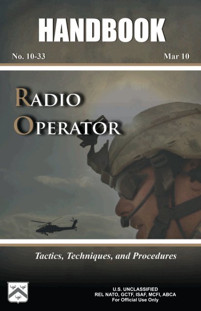
U.S. UNCLASSIFIED<br />
REL NATO, GCTF, ISAF, MCFI, ABCA<br />
For Official Use Only
Handling Instructions for CALL<br />
Electronic Media and Paper Products<br />
Center for Army Lessons Learned (CALL) authorizes official use of this CALL<br />
product for operational and institutional purposes that contribute to the overall<br />
success of U.S., coalition, and allied efforts.<br />
The information contained in this product reflects the actions of units in the field<br />
and may not necessarily be approved U.S. Army policy or doctrine.<br />
This product is designed for official use by U.S., coalition, and allied personnel and<br />
cannot be released to the public without the expressed written consent of CALL.<br />
This product has been furnished with the expressed understanding that it will be<br />
used for official defense-related purposes only and that it will be afforded the same<br />
degree of protection that the U.S. affords information marked “U.S.<br />
UNCLASSIFIED, For Official Use Only [FOUO]” in accordance with U.S. Army<br />
Regulation (AR) 380-5, section 5-2.<br />
Official military and civil service/government personnel, to include all coalition<br />
and allied partners may paraphrase; quote; or use sentences, phrases, and<br />
paragraphs for integration into official products or research. However, integration<br />
of CALL “U.S. UNCLASSIFIED, For Official Use Only [FOUO]” information into<br />
official products or research renders them FOUO, and they must be maintained and<br />
controlled within official channels and cannot be released to the public without the<br />
expressed written consent of CALL.<br />
This product may be placed on protected UNCLASSIFIED intranets within military<br />
<strong>org</strong>anizations or units, provided that access is restricted through user ID and<br />
password or other authentication means to ensure that only properly accredited<br />
military and government officials have access to these products.<br />
Regulations strictly forbid posting CALL “U.S. UNCLASSIFIED, For Official Use<br />
Only [FOUO]” documents to Department of Defense (DOD) Websites that do not<br />
restrict access to authorized personnel. AR-25-1, 15 Jul 2005, Army Knowledge<br />
Management and Information Technology, paragraph 6-4 n (2) (b) and DOD Web<br />
Site Administration Policy and Procedures (11 Jan 2002), Part II, paragraph 3.6.1<br />
require appropriate mechanisms to protect sensitive information.<br />
When no longer needed, all CALL “U.S. UNCLASSIFIED, For Official Use Only<br />
[FOUO]” paper products and electronic media will be shredded or destroyed using<br />
approved paper shredders or CDROM destroyers.<br />
To allied and coalition personnel:<br />
This information is furnished with the understanding that it is to be used for defense<br />
purposes only, that it is to be afforded essentially the same degree of security<br />
protection as such information is afforded by the United States, and that it is not to<br />
be revealed to another country or international <strong>org</strong>anization without the written<br />
consent of CALL.<br />
U.S. UNCLASSIFIED<br />
REL NATO, GCTF, ISAF, MCFI, ABCA<br />
For Official Use Only
Foreword<br />
The Signal Center of Excellence and the Center for Army Lessons Learned have<br />
jointly developed a <strong>Radio</strong> <strong>Operator</strong> <strong>Handbook</strong> for Soldiers assigned, attached, or<br />
task-<strong>org</strong>anized as radio operators. The intent of this handbook is to provide<br />
user/operator procedures, guidelines, and information that will enhance efficiency<br />
in the operation of currently fielded combat net radio systems.<br />
This handbook will assist Soldiers in developing unit training strategies that support<br />
the Army Force Generation cycle. By applying the information found in this<br />
handbook, Soldiers, leaders, and planners will be provided a solid foundation for<br />
unit radio operator training that will build individual confidence and competence<br />
while providing individuals with essential skills and knowledge related to radio<br />
operations.<br />
Like any other Soldier, a radio operator will be effective only if he is well trained<br />
and gains experience through the application of his skills. A good radio operator<br />
will enhance command and control at platoon through brigade level. This handbook<br />
is designed as a training support guide to supplement unit-level radio operator<br />
training and certification.<br />
U.S. UNCLASSIFIED<br />
REL NATO, GCTF, ISAF, MCFI, ABCA<br />
For Official Use Only<br />
RO III UPDATE<br />
i
<strong>Radio</strong> <strong>Operator</strong> <strong>Handbook</strong><br />
Table of Contents<br />
Introduction 1<br />
Chapter 1. User Information 5<br />
Chapter 2. Compromise Procedures 11<br />
Chapter 3. <strong>Radio</strong> Systems 17<br />
Chapter 4. Net Control Station Tasks 111<br />
Chapter 5. Global Positioning Systems 123<br />
Chapter 6. Controlled Cryptographic Equipment 141<br />
Appendix A. Julian Date Calendar 155<br />
Appendix B. World Time Zones and Time Conversion 157<br />
Appendix C. <strong>Radio</strong> Frequency Spectrum 161<br />
Appendix D. <strong>Radio</strong> Calls and Reports 163<br />
Appendix E. <strong>Radio</strong> Net Procedures 171<br />
Appendix F. Loss of Communication Procedures 175<br />
Appendix G. Medical Evacuation Request 177<br />
Appendix H. Glossary 181<br />
Appendix I. References 183<br />
Conclusion 185<br />
U.S. UNCLASSIFIED<br />
REL NATO, GCTF, ISAF, MCFI, ABCA<br />
For Official Use Only<br />
RO III UPDATE<br />
iii
CENTER FOR ARMY LESSONS LEARNED<br />
Center for Army Lessons Learned<br />
Director Colonel Thomas Joseph Murphy<br />
Division Chief Ge<strong>org</strong>e J. Mordica II<br />
CALL Analysts Ralph Nichols<br />
Tom Odom<br />
Marvin Decker<br />
Contributing Authors Major Craig Cardon<br />
Major Brian L. Williams<br />
Major Brian Lionberger<br />
Signal Center Author Yvonn B. Barnes<br />
Signal Center Editor Aileen Davila<br />
Production Coordinator Kristine Bell<br />
Graphic Artist Julie Gunter<br />
Distribution Manager Candice Miller<br />
The Secretary of the Army has determined that the publication of this periodical is<br />
necessary in the transaction of the public business as required by law of the<br />
Department.<br />
Unless otherwise stated, whenever the masculine or feminine gender is used, both<br />
are intended.<br />
Note: Any publications (other than CALL publications) referenced in this product,<br />
such as ARs, FMs, and TMs, must be obtained through your pinpoint distribution<br />
system.<br />
iv<br />
U.S. UNCLASSIFIED<br />
REL NATO, GCTF, ISAF, MCFI, ABCA<br />
For Official Use Only
Introduction<br />
Selecting a <strong>Radio</strong> <strong>Operator</strong><br />
Ralph D. Nichols, Senior Military Analyst, Center for Army Lessons<br />
Learned and MAJ Brian Lionberger, Center for Army Lessons Learned<br />
The unit radio operator (RO) provides platoon- to brigade-level maneuver leaders a<br />
command and control capability that is critical to mission success. The RO is more<br />
than a Soldier who carries the radio for the commander, serves as the commander’s<br />
driver, or provides the commander personal security, although he often serves in<br />
these functions. The RO is the commander’s tactical information manager. The<br />
process for selecting and training an RO varies widely and is based on the role the<br />
unit commander intends the RO to perform; however, there are common factors that<br />
every maneuver RO should possess in order to enable effective unit command and<br />
control.<br />
Unit commanders should consider the following factors when selecting, training,<br />
and employing their ROs. ROs should:<br />
Be able to competently apply the four principles of providing effective<br />
communications: plan, manage, train, and maintain.<br />
Be able to obtain and maintain a Secret security clearance.<br />
Be able to receive a message and communicate it effectively.<br />
Be proficient in both traditional analog (map and compass and azimuth<br />
and pace count) and enhanced digital-enabled (blue force tracking [BFT],<br />
Precision Lightweight Global Positioning System Receiver, and/or Force<br />
XXI battle command—brigade and below [FBCB2]) land navigation<br />
skills).<br />
Be in outstanding physical condition, especially if the unit conducts<br />
dismounted operations for any length of time. The added weight of the<br />
communication equipment and supplies increases the difficulty of<br />
movement.<br />
Be technically proficient in the operation of all required communications<br />
systems and understand the limitations of that equipment. A dismounted<br />
RO must be proficient with secure frequency modulation, tactical<br />
satellite, and high-frequency radios. The RO must also be proficient with<br />
BFT and/or FBCB2 terminals, as most command vehicles and some lift<br />
aircraft have these systems.<br />
Understand the ranges and limitations of the communication equipment.<br />
Know and apply employment techniques (such as positioning) and field<br />
expedients (such as long-wire antennas) to mitigate the limitations<br />
imposed by the environment. Operating in a dense urban environment,<br />
traversing long distances and/or mountainous terrain, or inclement<br />
weather can degrade communication range capabilities.<br />
U.S. UNCLASSIFIED<br />
REL NATO, GCTF, ISAF, MCFI, ABCA<br />
For Official Use Only<br />
RO III UPDATE<br />
1
CENTER FOR ARMY LESSONS LEARNED<br />
2<br />
Possess and sustain combat driving skills and understand unit convoy<br />
procedures in situations where the RO is also the commander’s driver.<br />
The RO should be cross-trained and able to assume the vehicle gunner’s<br />
duties in extreme situations. The RO must have the ability to engage the<br />
enemy with lethal force when required.<br />
Be a certified combat lifesaver. Understand and be able to quickly and<br />
effectively apply appropriate medical evacuation procedures when<br />
required.<br />
Be familiar with Field Manual (FM) 1-02, Terms and Graphics. ROs<br />
must understand that operational terms have specific meanings, and the<br />
terms cannot be changed or paraphrased when receiving a message. They<br />
must understand graphics so they can mark a map when receiving a spot<br />
report; situation report; or size, activity, location, unit/uniform, time, and<br />
equipment report.<br />
Be familiar with FM 6-02.53, Tactical <strong>Radio</strong> Operations. This FM serves<br />
as a reference document for tactical radio systems. It also provides<br />
doctrinal guidance for using tactical radios on the modern battlefield. The<br />
FM targets operators, supervisors, and planners to provide a common<br />
reference for tactical radios. It provides basic guidance and gives the<br />
system operator and planner the necessary steps for network planning,<br />
operations, interoperability, and equipment capabilities.<br />
Be familiar with FM 1-02.1, Brevity Codes. If operating in a joint or<br />
coalition/allied environment, ROs must be familiar with appropriate<br />
manuals and regulations.<br />
Have a general understanding of the military decisionmaking process.<br />
The RO must understand and be able to communicate the commander’s<br />
intent at all times.<br />
Be able to use a headset to monitor the commander’s communications.<br />
Headsets drown out surrounding noise and enable clearer and<br />
distraction-free communication.<br />
Be trustworthy and discreet. The RO will see and hear much more than<br />
most other junior enlisted Soldiers and is expected to maintain<br />
confidentiality.<br />
Be able to complete a call for fire. In many unit standing operating<br />
procedures (SOPs), the RO automatically submits a call for fire, “at my<br />
command,” based on a subordinate’s report of troops in contact. This<br />
technique allows for a more rapid employment of indirect fires without<br />
loss of command authority for execution.<br />
Be able to rapidly execute the unit’s SOP for assumption of command in<br />
the event the commander becomes a casualty. Some unit SOPs give the<br />
RO significant authority in continuing operations when the commander<br />
becomes a casualty and before the next leader in the chain of command<br />
assumes control. Judgment, maturity, situational awareness, and a clear<br />
U.S. UNCLASSIFIED<br />
REL NATO, GCTF, ISAF, MCFI, ABCA<br />
For Official Use Only
understanding of commander’s intent are all essential qualities for an RO<br />
in these situations.<br />
Be able to train subordinate, replacement, or additional ROs as the unit<br />
mission dictates.<br />
Possess intangible personal qualities such as sound judgment, maturity,<br />
and ability to work well with others (team player). The RO must be<br />
adaptive, flexible, and able to think and act independently. The RO must<br />
be intelligent and maintain composure under duress and have the personal<br />
courage and stamina to effectively perform and execute with little or no<br />
guidance.<br />
Use these personal characteristics and skill sets when selecting an RO. Like any<br />
Soldier, an RO will be effective only to the extent that the commander and unit<br />
leadership rigorously select, train, and sustain that Soldier for that job. A good RO<br />
will enhance command and control at the platoon through brigade levels.<br />
U.S. UNCLASSIFIED<br />
REL NATO, GCTF, ISAF, MCFI, ABCA<br />
For Official Use Only<br />
RO III UPDATE<br />
3
Chapter 1<br />
User Information<br />
This chapter provides a compendium of basic user information and references for<br />
all radio operators (ROs). It is not a complete guide to the Single-Channel Ground<br />
and Airborne <strong>Radio</strong> System (SINCGARS) or RO duties. Instead, it is a starting<br />
point and a handy reference for any Soldier who may be tasked with RO duties.<br />
Because the RO is the small-unit leader’s walking, talking, tactical operations<br />
center, this chapter also provides a similar starting point for unit leaders, from team<br />
to battalion, who must be familiar with the SINCGARS and RO duties.<br />
1. Purpose. This handbook establishes procedures, guidelines, and information on<br />
operating the various radio systems currently being used. It is designed to<br />
supplement unit-level RO training and certification and act as a quick reference for<br />
ROs when faced with a communications problem.<br />
2. General.<br />
a. SINCGARS. There are several ground unit versions of SINCGARS<br />
(RT-1523/A/B/C/D/E/F models). The integrated communications system<br />
(ICOM) version consists of RT-1523A/B, the systems improvement<br />
program (SIP) version is RT-1523C/D, and the advanced SIP (ASIP)<br />
version is RT 1523E/F.<br />
The SINCGARS ASIP is a user-owned and operated solid-state frequency<br />
modulation (FM) combat net radio (CNR) that operates in the<br />
30.000–87.995 megahertz (MHz) frequency range in the single-channel<br />
(SC) or frequency-hopping (FH) mode. The SINCGARS ASIP increases the<br />
performance of the SINCGARS SIP; it also increases its operational<br />
capability in support of the tactical Internet. The ASIP is compatible with<br />
the older SINCGARS and with North Atlantic Treaty Organization forces in<br />
SC, squelch off mode. It provides electronic warfare protection and a<br />
reduced electromagnetic signature in the FH mode. The SINCGARS ASIP<br />
radio incorporates an enhanced SIP (ESIP) waveform. The waveform<br />
includes optimizations to the algorithms of the noisy channel avoidance<br />
scheme, the time of day tracking scheme, and the end of message scheme.<br />
b. Squad radios. To meet the communication demands among squad<br />
members, the Army allows units to purchase commercial, off-the-shelf<br />
(COTS) systems. The two most commonly used COTS systems are the EF<br />
Johnson and ICOM radios. It is important to remember these radios have<br />
limited capabilities.<br />
c. AN/PSC-5C/5D (Spitfire). This radio was built to replace the AN/PSC-3.<br />
The Spitfire can scan up to five line-of-sight (LOS) or dedicated satellite<br />
communications (SATCOM) radio voice operation nets. Scanning<br />
combinations of cipher text (VINSON encryption) and plain text nets is<br />
allowed in voice mode only. The Spitfire operates in SATCOM modes. The<br />
Spitfire provides range extension for both SINCGARS and Spitfire radios.<br />
Use the AN/PSC-5 for beyond-line-of-sight (BLOS) wireless network<br />
extension of SINCGARS nets. Each net requires a SINCGARS and<br />
AN/PSC-5 terminal connected for wireless network extension. (For more<br />
U.S. UNCLASSIFIED<br />
REL NATO, GCTF, ISAF, MCFI, ABCA<br />
For Official Use Only<br />
RO III UPDATE<br />
5
CENTER FOR ARMY LESSONS LEARNED<br />
6<br />
information on the AN/PSC-5, refer to Technical Manual [TM]<br />
11-5820-1130-12&P.)<br />
d. AN/PRC-<strong>10</strong>4A. This radio consists of the RT-1209, amplifier/coupler<br />
amplitude modulation (AM)-6874, antennas, and handsets. It is a low-power<br />
radio that operates in the 2–29.999 MHz frequency range and passes secure<br />
command and control (C2) information over medium to long distances and<br />
varying degrees of terrain features that would prevent the use of very high<br />
frequency (VHF)/FM CNR. It provides 280,000 tunable channels in <strong>10</strong>0<br />
hertz (Hz) steps and has automatic antenna tuning. (Refer to TM<br />
11-5820-919-12 for more information on the AN/PRC-<strong>10</strong>4A.)<br />
e. AN/VRC-<strong>10</strong>4(V)1 and (V)3. These are vehicular radio systems that<br />
provide units with BLOS communications, without having to rely on<br />
satellite availability on a crowded communications battlefield. The systems’<br />
manpack and vehicular configurations ensure units have reliable<br />
communications while on the move and allow for rapid transmission of data<br />
and imagery.<br />
f. AN/PRC-117F. This is an advanced, multiband, multi-mission manpack<br />
radio that provides reliable tactical communications performance in a small,<br />
lightweight package that can maximize user mobility. The AN/PRC-117F is<br />
a based, fully digital, software-controlled, voice and data transceiver<br />
multiprocessor. The AN/PRC-117F is capable of providing LOS,<br />
SATCOM, electronic counter countermeasures, and FH operations<br />
(SINCGARS and HAVEQUICK) and is compatible with all tactical<br />
VHF/ultra high frequency (UHF) radios. (Note: The AN/VRC-<strong>10</strong>3 is the<br />
vehicular version of the AN/PRC-117F.)<br />
g. Falcon III AN/PRC-117G. This manpack, wideband networking radio<br />
when combined with the RF-7800B provides automatic and secure range<br />
extension, connection to out-of-range networks, and entry into the Internet<br />
by using satellite-based, wideband BLOS communications.<br />
h. AN/PRC-148 multiband inter/intra team radio. This radio is capable of<br />
operating in clear (analog), secure voice (digital), and secure data (digital)<br />
modes. It operates over a 30–512 MHz frequency rage in FM, AM, or<br />
shaped binary phase keying (SBPSK) radio frequency.<br />
i. AN/PRC-150 (Harris) I advanced high frequency(HF)/VHF tactical radio.<br />
This radio provides units with state-of-the-art HF radio capabilities in<br />
support of fast moving, wide area operations. HF signals travel longer<br />
distances over the ground than the VHF (SINCGARS) or UHF Enhanced<br />
Position Location and Reporting System signals do because they are less<br />
affected by factors such as terrain or vegetation.<br />
j. ANPRC-152. This is a Joint Tactical <strong>Radio</strong> System compliant with its<br />
software communication architecture (SCA), programmable cryptography<br />
(VINSON KY-57/58), and multiple waveform capability. It can operate in<br />
the FM and AM bands and has UHF SATCOM capability using weather<br />
narrowband or wideband channels and is able to interface with public safety<br />
communication systems within the United States.<br />
U.S. UNCLASSIFIED<br />
REL NATO, GCTF, ISAF, MCFI, ABCA<br />
For Official Use Only
k. Controlled cryptographic equipment.<br />
(1) The AN/CYZ-<strong>10</strong> automated net control device (ANCD) is a<br />
handheld device capable of receiving, storing, and transferring data<br />
between ANCDs or between an ANCD and a SINCGARS radio. The<br />
primary application for this device is to fill the SINCGARS with FH<br />
data, time, communications security (COMSEC), and loadset<br />
information. ANCDs are nonrepairable, controlled cryptographic<br />
items (CCIs) and must be stored according to Technical Bulletin<br />
340-1 (change 1). An ANCD loaded with secret information must be<br />
stored in a three-combination safe. ANCDs that are not loaded must<br />
be secured with no less than two barrier protection layers (a locked<br />
door and wall locker using a 200 series lock for example).<br />
(2) The AN/PYQ-<strong>10</strong> simple key loader (SKL) was designed as a<br />
replacement for the AN/CYZ-<strong>10</strong>, ANCD. A limited understanding of<br />
the Electronic Key Management System operating environment is<br />
helpful in understanding the operation of the SKL. The hardware<br />
platform that hosts the SKL software (including the secure library) is<br />
a vendor-supplied, ruggedized personal digital assistant device<br />
equipped with a KOV-21 personal computer memory card<br />
international association card. The SKL is not equipped with a hard<br />
drive, so all programs are stored in nonvolatile flash memory.<br />
l. Global Positioning Systems (GPSs).<br />
(1) The AN/PSN-11 Precision Lightweight GPS Receiver (PLGR) is<br />
a handheld GPS. The primary application for this device is precision<br />
position location and land navigation via programmable waypoints.<br />
The secondary application for this device is to update and verify the<br />
date and time in SINCGARS. The PLGR is a high-dollar item and<br />
should be safeguarded accordingly.<br />
(2) The Defense Advanced GPS Receiver (DAGR) is the PLGR’s<br />
replacement. The DAGR incorporates anti-jam improvements for<br />
enhanced protection and is the first U.S. handheld GPS receiver<br />
program to include the next generation security device, Selective<br />
Availability Anti-Spoofing Module. The DAGR’s dual radio<br />
frequency front end allows continuous tracking of both the L1 and<br />
L2 GPS satellite frequencies. Even when turned off, a precision time<br />
source runs continuously to allow rapid acquisition of the GPS<br />
satellites when the receiver is turned on. This system is a great<br />
improvement over the PLGR.<br />
Note: The SINCGARS radios, ANCD, and SKL are CCIs and require<br />
double-barrier protection according to Department of the Army Pamphlet 25-380-2.<br />
All unattended SINCGARS radios will be zeroed. <strong>Radio</strong>s will be reloaded when<br />
required using the ANCD/SKL.<br />
U.S. UNCLASSIFIED<br />
REL NATO, GCTF, ISAF, MCFI, ABCA<br />
For Official Use Only<br />
RO III UPDATE<br />
7
CENTER FOR ARMY LESSONS LEARNED<br />
3. Operating procedures.<br />
8<br />
a. Net synchronization time (NET).<br />
(1) SINCGARS radios have an internal master clock. Each channel<br />
also has the ability to maintain separate time. Time is primarily<br />
loaded into the radio via a GPS device or can be manually set. If the<br />
ANCD is used, ensure the time in the ANCD has accurate Zulu time<br />
stored. GPS Zulu time is the standard time zone used for all radios.<br />
(2) The Zulu time stored in a SINCGARS radio will drift<br />
significantly over time and if loaded into the ASIP will not allow<br />
communications with other net members. All ROs must verify<br />
accurate time in the ASIP after loading their radios. All ROs must<br />
also maintain accurate time (hours, minutes, and seconds) on a<br />
digital watch to quickly verify time. Time must be within + or – 4<br />
seconds to communicate with other SINCGARS. Accurate Zulu time<br />
can be obtained:<br />
By calling the atomic clock at Defense Switching Network<br />
762-1401 or commercial (202) 762-1401.<br />
Via GPS (must be + or – 1 second).<br />
Via HF radio (PRC-04) at the top of the hour on any 5<br />
kilohertz frequency.<br />
(3) The SINCGARS Julian date (JD) is the last two digits of the full<br />
JD. Refer to Appendix A for the correct JD. The JD is also<br />
automatically loaded via the ANCD. If a net member loads the<br />
incorrect JD or accidentally changes the JD, all communication with<br />
other net members will be lost.<br />
(4) The net control station (NCS) will always maintain accurate time<br />
and will operate a radio in the frequency hopping master (FH-M)<br />
mode during FH operations. The NCS for each net is the only radio<br />
authorized to operate in the FH-M mode. This procedure will ensure<br />
time accuracy throughout the net. If the NCS radio fails during any<br />
part of the mission, the alternate NCS will switch its radio to the<br />
FH-M mode.<br />
b. The battalion standard for initial net opening is a hot start net opening<br />
procedure. Chapter 3 covers this procedure in detail.<br />
c. The passive late net entry procedure allows a radio with the correct hopset<br />
and COMSEC information but inaccurate time (+ or – 59 seconds) to enter a<br />
net. Chapter 3 covers this procedure in detail.<br />
U.S. UNCLASSIFIED<br />
REL NATO, GCTF, ISAF, MCFI, ABCA<br />
For Official Use Only
d. Loadset.<br />
(1) Loadsets are comprised of the following components:<br />
Transmission security key: frequency hop data<br />
Esets: net identifications (IDs), for example, F302<br />
COMSEC keys (transmission encryption key and key<br />
encryption key): transmission encryption keys<br />
Lockout sets: restricted frequencies within the frequency<br />
hop data<br />
(2) The ANCD transfers a loadset to a SINCGARS. This loadset is<br />
transferred by a menu-driven procedure during normal loading<br />
procedures of the SINCGARS with the ANCD.<br />
(3) Net IDs are normally fixed and will follow the numbering<br />
scheme in the note below. Specific net IDs within the below listed<br />
ranges are designated in the unit’s signal operating instructions<br />
(SOI).<br />
Note<br />
The following are sample unit standards only and may change for real world<br />
contingencies or deployments:<br />
FH000–099 Theater/Joint<br />
FH<strong>10</strong>0–299 Corps/Service<br />
FH300–399 1st Brigade (BDE)<br />
FH400–499 2nd BDE<br />
FH500–599 3rd BDE<br />
FH600–699 Aviation BDE<br />
FH700–799 Fires BDE<br />
FH800–899 Division Support Command<br />
FH900–999 Division Headquarters<br />
U.S. UNCLASSIFIED<br />
REL NATO, GCTF, ISAF, MCFI, ABCA<br />
For Official Use Only<br />
RO III UPDATE<br />
9
CENTER FOR ARMY LESSONS LEARNED<br />
<strong>10</strong><br />
e. Operations security (OPSEC) is defined as any measure an operator takes<br />
to safeguard information from the enemy. OPSEC can be anything from<br />
minimizing the number of net IDs loaded into a radio to zeroing an ANCD<br />
or radio if capture by the enemy is imminent. These actions deny the enemy<br />
the ability to exploit the ANCD or radio to obtain intelligence information<br />
to use against U.S. forces. All personnel assigned to, attached to, or under<br />
the operational control of the battalion will follow these procedures to<br />
maximize OPSEC.<br />
(1) Loadsets contain only the primary net used by the operator. If the<br />
RO requires additional nets, he will manually load the radio with the<br />
required net, minimizing the number of channels used.<br />
(2) ANCDs only contain the loadset and COMSEC required by the<br />
operator.<br />
(3) New editions of the SOI and COMSEC should not be distributed<br />
below the battalion level until authorized by the BDE signal officer.<br />
(4) All ROs must know all compromise procedures and code words<br />
prescribed in Chapter 2 and understand the steps for each procedure.<br />
(5) Safeguard any radio cheat sheets that list call signs and net IDs,<br />
and account for cheat sheets according to classification such as for<br />
official use only, confidential, or secret. Whenever possible,<br />
memorize this information.<br />
f. Common prowords are words used on a regular basis while conducting<br />
radio operations. They are not interchangeable; the meanings are specific<br />
and clear to the receiver. For example, consider the prowords “say again”<br />
and “repeat.” “Say again” means to repeat the last transmission while<br />
“repeat” refers to fire support, to fire the last mission again.<br />
U.S. UNCLASSIFIED<br />
REL NATO, GCTF, ISAF, MCFI, ABCA<br />
For Official Use Only
Chapter 2<br />
Compromise Procedures<br />
Compromise of sensitive signal information is inevitable and always unwelcome.<br />
The effects of compromise can be minimized through common sense precautions<br />
and standardized corrective measures embedded in unit standing operating<br />
procedures (SOPs). The key concept in dealing with compromise is a common<br />
understanding of those SOPs based on repetitive drills. This chapter offers units a<br />
possible template for establishing compromise procedures. Like all standardized<br />
procedures, these SOPs are absolutely worthless if everyone in a unit does not<br />
practice and understand them.<br />
Note: The codewords/definitions used below are provided as examples. Actual<br />
codewords/definitions will be published in the unit’s tactical SOPs (TACSOPs) and<br />
signal operating instructions (SOI).<br />
1. Purpose. This chapter establishes the guidelines designed to standardize the<br />
process for executing compromise procedures. The compromise procedures reflect<br />
the steps used by the unit.<br />
2. General. A compromise is defined as any communications security (COMSEC)<br />
fill device or COMSEC-filled and functioning radio that falls into enemy hands<br />
before the radio operator (RO) can zero the device. The procedures listed below<br />
detail actions for ROs to take to minimize compromises, if a compromise is<br />
imminent, and after a net becomes compromised.<br />
3. Procedures.<br />
a. Minimizing compromise.<br />
(1) Effective battle tracking enables the battle staff to attain mutual<br />
situational awareness of the battlefield and the ability to track the<br />
execution of tactical operations. Battle tracking is achieved by the<br />
integration of the staff through teamwork and an interactive flow of<br />
information within the command post. Knowing what is loaded in a<br />
particular device at the battalion and brigade level mitigates the<br />
severity of a compromise.<br />
(2) Automated net control devices (ANCDs) or simple key loaders<br />
(SKLs) are not distributed below the infantry company headquarters<br />
or below antitank platoon headquarters level. Combat multipliers<br />
will not deploy with ANCDs or SKLs and will receive all radio fills<br />
from the supported maneuver element. Ensure all controlled<br />
cryptographic items are properly accounted for and secured at all<br />
times.<br />
(3) SOI data are not distributed below battalion level. The new<br />
challenge and password is announced over a secure command net<br />
daily at 0<strong>10</strong>0 hours (Zulu).<br />
U.S. UNCLASSIFIED<br />
REL NATO, GCTF, ISAF, MCFI, ABCA<br />
For Official Use Only<br />
RO III UPDATE<br />
11
CENTER FOR ARMY LESSONS LEARNED<br />
12<br />
(4) All command vehicles leaving the tactical operations center<br />
(TOC) or headquarters command post (CP) secure their ANCDs at<br />
that TOC or CP.<br />
(5) Excess ANCDs within a deployed unit are zeroed.<br />
b. Imminent compromise.<br />
(1) If carrying an ANCD, the RO immediately zeroes the ANCD by<br />
hitting the red zero key four times, then removes the COMSEC<br />
encryption key and destroys it. By destroying the ANCD’s CIK, the<br />
ANCD is inoperable.<br />
(2) If carrying an SKL, the operator needs to depress the zeroize<br />
button located on the top right of the SKL protected by a swivel cap.<br />
Depressing the zeroize button causes the KOV-21 information<br />
security (INFOSEC) card to begin a zeroization process of the SKL<br />
unmanned aircraft system mission data. Once this process is started,<br />
it cannot be stopped. To zeroize the KOV-21 INFOSEC card, swing<br />
open the swivel cap and depress and hold down the red button for<br />
more than one second—zeroization is immediate.<br />
(3) <strong>Operator</strong>s announce on the radio, “ALL STATIONS THIS NET,<br />
THIS IS (call sign) WATERGATE, WATERGATE,<br />
WATERGATE!” and then immediately zero the COMSEC by<br />
turning the function knob to Z. This message alerts other net<br />
members that you have zeroed your radio’s COMSEC because you<br />
are being captured. You may still use the radio but only in a<br />
nonsecure mode until you can receive another ANCD fill.<br />
c. Compromise confirmed. Once a compromise is confirmed or a decision is<br />
made by a commander to treat the incident as a compromise, the following<br />
actions by the net control station (NCS) will take place.<br />
(1) VENUS will be used to announce that a compromise occurred.<br />
This code word will be used as follows: “Venus, Venus, Venus.<br />
Stand by, over.”<br />
(2) JUPITER will be used to change the operating SOI to a new<br />
edition. This code word will be used as follows: “Guidons, guidons,<br />
Jupiter edition __________, (date-time group [DTG])<br />
____________, Acknowledge in sequence, over.”<br />
(3) PLUTO will be used to add two days to the existing Julian date<br />
(JD). This code word will be used as follows: “Guidons, guidons,<br />
Pluto, Pluto, Pluto ________________, Acknowledge in sequence,<br />
over.”<br />
(4) MERCURY will be used to subtract two days from the existing<br />
JD. This code word will be used as follows: “Guidons, guidons,<br />
Mercury, Mercury, Mercury, over. Respond in sequence, over.”<br />
U.S. UNCLASSIFIED<br />
REL NATO, GCTF, ISAF, MCFI, ABCA<br />
For Official Use Only
(5) NEPTUNE will be used to switch to predesignated net<br />
identifications (IDs). The code word WHEEL will be followed with<br />
the number designated to represent the predesignated net ID within<br />
the SOI. WHEEL 1 and 2 net IDs will be designated within the SOI<br />
or published with the signal annex supporting the mission. WHEEL<br />
X-RAY is used to return to the original net ID. This code word will<br />
be used as follows: “Guidons, guidons, Wheel __________, DTG<br />
__________, acknowledge, over.”<br />
(6) URANUS will be used to announce that the net should prepare to<br />
receive an automatic rekey using manual keying over the air<br />
(OTAR). This code word will be used as follows: “Guidons,<br />
guidons, Uranus, Uranus, Uranus, DTG ___________, acknowledge<br />
in sequence, over.” This procedure allows an NCS to transfer a<br />
transfer encryption key (TEK) (not a key encryption key [KEK])<br />
electronically by OTAR to other NCSs.<br />
(7) MARS will be used to announce that the net should prepare to<br />
receive an automatic rekey (OTAR). This code word will be used as<br />
follows: “Guidons, guidons, Mars, Mars, Mars, DTG ___________,<br />
acknowledge, over.” This procedure allows an NCS to transfer a<br />
TEK (not a KEK) electronically by OTAR to other NCSs.<br />
d. After a compromise.<br />
(1) If you suspect a net is compromised, do not announce “THIS<br />
NET IS COMPROMISED” over the net. Use an alternate secure net<br />
to notify your higher headquarters or announce over the net, “ALL<br />
STATIONS THIS NET, THIS IS (call sign) RED EYE, RED EYE,<br />
RED EYE.” This message alerts other net members that you suspect<br />
the net is compromised, and all classified traffic must come to a halt.<br />
(2) Compromised nets continue to operate on the compromised TEK<br />
until the NCS directs a change of the TEK or net ID. The directive<br />
will only come from the battalion signal officer.<br />
(3) Once the mission allows, the NCS directs a net ID or TEK<br />
change.<br />
Example:<br />
Net ID:<br />
RATTLESNAKE 1: Change to STRIKE NET 1<br />
RATTLESNAKE 2: Change to STRIKE NET 2<br />
RATTLESNAKE 3: Change to original NET ID<br />
U.S. UNCLASSIFIED<br />
REL NATO, GCTF, ISAF, MCFI, ABCA<br />
For Official Use Only<br />
RO III UPDATE<br />
13
CENTER FOR ARMY LESSONS LEARNED<br />
14<br />
An alternate method is to change the Julian date (JD) on the radio<br />
net using code words and leaving the net ID alone.<br />
Example:<br />
JD:<br />
WARRIOR SPIRIT 1: Change JD + 3<br />
WARRIOR SPIRIT 2: Change JD + 5<br />
WARRIOR SPIRIT 3: Change JD + 7<br />
(4) The NCS directs an OTAR using either the automatic remote<br />
keying method (AK) or manual remote keying (MK) method.<br />
Chapter 4 covers the procedures for both tasks. After execution of<br />
either method, the NCS conducts a radio check with all net<br />
members. An alternate NCS acts as a sweeper and remains on the<br />
old net ID or TEK until all members are notified and comply with<br />
the change.<br />
(5) Actual STRIKE net IDs are found in the SOI and must be<br />
memorized. Do not write down STRIKE net IDs anywhere.<br />
(6) Once the new net is established, it is clear for classified traffic<br />
again.<br />
(7) Code words used to initiate change of SOI editions are:<br />
COBRA: Change to B edition TEK/SOI<br />
PYTHON: Change to C edition TEK/SOI<br />
U.S. UNCLASSIFIED<br />
REL NATO, GCTF, ISAF, MCFI, ABCA<br />
For Official Use Only
(8) The battalion has the capability to send new SOI information<br />
electronically via the Advanced System Improvement Program and<br />
ANCD using the broadcast method. The battalion will only use this<br />
method as a last resort if other means of disseminating the SOI<br />
information prove impossible or impractical. The broadcast method<br />
is a very time-intensive process because the ANCD will only process<br />
data at 16 kilobytes per second, and normally it allows units to<br />
receive one time period at a time. The procedure includes a polling<br />
feature that allows the NCS to determine by automatic query if up to<br />
16 net members (designated by special ID numbers) did or did not<br />
receive the SOI information sent by broadcast.<br />
(a) The following list assigns polling ID numbers for each<br />
net member:<br />
Unit/Section Polling Number<br />
A Company 1<br />
B Company 2<br />
C Company 3<br />
D Company 4<br />
Administrative and logistical<br />
operations center<br />
5<br />
Combat trains 6<br />
Wireless network extension 7<br />
(b) SOI broadcasts can handle up to 16 polling numbers.<br />
Polling numbers 8–16 will only be assigned when required.<br />
Note: The codewords/definitions used in this chapter are provided as examples.<br />
Actual codewords/definitions will be published in the unit’s TACSOP and SOI.<br />
U.S. UNCLASSIFIED<br />
REL NATO, GCTF, ISAF, MCFI, ABCA<br />
For Official Use Only<br />
RO III UPDATE<br />
15
Chapter 3<br />
<strong>Radio</strong> Systems<br />
The family of combat net radios is comprised of intra-squad radios, Single-Channel<br />
Ground and Airborne <strong>Radio</strong> System (SINCGARS) radios, and single-channel<br />
tactical satellite radios. These are the essential command and control (C2) systems<br />
directly supporting the warfighter during daily operations. The most common radio<br />
systems currently being fielded are the EF Johnson, Integrated communications<br />
security (ICOM), SINCGARS, AN/PRC-148 Multiband Inter/Intra Team <strong>Radio</strong><br />
(MBITR), AN/PRC-152 (Harris), AN/PRC-117F, and the AN/PSC-5. These radios<br />
are the base components for many different configurations. There are tasks common<br />
to all radios; however, some of the newer systems such as the PRC-148 or PRC-152<br />
possess increased capabilities for radio operators (ROs). One of the added features<br />
of the newer radios is the ability to be programmed using a personal computer (PC).<br />
This handbook will focus on essential tasks that an RO must accomplish on a<br />
routine basis such as:<br />
• Set-up the radio for operation.<br />
Load a single-channel (SC) frequency (FREQ).<br />
Load communications security (COMSEC).<br />
Load SINCGARS hopset.<br />
Clone radio (EF Johnson, AN/PRC-148, and AN/PRC-152).<br />
Receive an electronic remote fill (ERF), SINCGARS advanced systems<br />
improvement program (ASIP).<br />
Receive an over-the-air re-key (OTAR).<br />
Activate emergency location beacon (AN/PRC-148 and AN/PRC-152).<br />
Change net identification (ID).<br />
Intra-squad <strong>Radio</strong>s<br />
Intra-squad radios are the simplest radios used by Soldiers today. They are small,<br />
lightweight, and have a reduced capacity when compared to most other systems.<br />
Operation is intuitive. Nonetheless, all Soldiers and ROs should be familiar with<br />
these systems. The most common types are the newer EF Johnson 5<strong>10</strong>0 ES Model 1<br />
and the older ICOM.<br />
EF Johnson 5<strong>10</strong>0 ES Model 1<br />
The EF Johnson 5<strong>10</strong>0 ES Model 1 radio is a commercial off-the-shelf (COTS)<br />
system typically used for intra-squad communication. It meets the Project 25<br />
standards for digital radio communications for use by federal, state, and local public<br />
safety agencies.<br />
U.S. UNCLASSIFIED<br />
REL NATO, GCTF, ISAF, MCFI, ABCA<br />
For Official Use Only<br />
RO III UPDATE<br />
17
CENTER FOR ARMY LESSONS LEARNED<br />
General Information<br />
Frequency range 380–470 megahertz (MHz) ultra-high frequency<br />
(UHF)<br />
Channels 48 programmable channels (3 zones with 16<br />
channels each)<br />
Channel spacing 12.5/25 MHz<br />
Power requirement 7.2 direct current (DC)<br />
Operating temperature –22° Fahrenheit (F) to +140° F<br />
Approximate range 20 miles at 4W<br />
Approximate battery life <strong>10</strong> hours<br />
Notes<br />
1. The radio’s range depends greatly on the terrain. The 20-mile approximate<br />
range assumes a clear line of sight (LOS) with little to no interference. The range<br />
will be much less in urban areas.<br />
2. Battery life is influenced by environmental conditions and the condition of the<br />
battery. Over time, a battery loses its ability to hold a charge. Batteries that no<br />
longer hold a charge for an adequate amount of time should be replaced.<br />
18<br />
Channel Switch<br />
Power On-Off/Volume Adj<br />
LED<br />
Microphone<br />
Speaker<br />
Antenna<br />
Figure 3-1. EF Johnson 5<strong>10</strong>0 ES<br />
U.S. UNCLASSIFIED<br />
REL NATO, GCTF, ISAF, MCFI, ABCA<br />
For Official Use Only
EF Johnson operator task 1. <strong>Radio</strong> setup:<br />
Subtask Action<br />
a. Install PC Configure 1. Have the unit’s information<br />
management officer load the program<br />
onto a laptop<br />
b. Conduct precombat checks 1. Inspect the radio and antenna for<br />
defects<br />
2. Attach battery to radio<br />
3. Attach antenna<br />
c. Determine the radio’s<br />
1. Open the PC Connect software on<br />
programmable options<br />
the computer<br />
2. Connect the radio to the computer<br />
3. Select the RADIO menu parameter<br />
4. Select the SERIES menu parameter<br />
5. Select 5<strong>10</strong>0 PORTABLE<br />
6. Select TRANSFER and then select<br />
READ OPTIONS FROM RADIO<br />
EF Johnson operator task 2. Load a single channel:<br />
Subtask Action Result<br />
a. Power on<br />
the radio<br />
b. Set the<br />
volume<br />
c. Set the<br />
channel<br />
d. Conduct<br />
radio check<br />
1. Turn the on/off volume<br />
switch<br />
1. Move the volume switch<br />
to the desired level<br />
1. Rotate the channel knob to<br />
the appropriate channel<br />
number<br />
Note: All channels must be<br />
preprogrammed.<br />
1. <strong>Radio</strong> performs a self-test<br />
2. A tone sounds<br />
3. The light-emitting diode<br />
comes on (amber)<br />
N/A<br />
N/A N/A<br />
U.S. UNCLASSIFIED<br />
REL NATO, GCTF, ISAF, MCFI, ABCA<br />
For Official Use Only<br />
The radio is ready for<br />
operation<br />
RO III UPDATE<br />
There will be a continuous<br />
tone if the channel was not<br />
programmed<br />
19
CENTER FOR ARMY LESSONS LEARNED<br />
EF Johnson operator task 3. Load COMSEC:<br />
Subtask Action<br />
a. Check encryption capability 1. Using the PC Connect software, select<br />
the TRANSFER option<br />
2. Select READ OPTIONS FROM RADIO<br />
3. If no entry here, delete number<br />
Note: The EF Johnson radio is capable of using DES [data encryption<br />
standard]. The manufacturer must enable this feature.<br />
ICOM <strong>Radio</strong> IC-F43 (Squad <strong>Radio</strong>)<br />
ICOMs are durable, short-range radios used at the platoon and squad levels. These<br />
simple radio systems are computer programmable. It is not complicated to set<br />
ICOM radios up for communications.<br />
General Information<br />
Frequency range 400–430 MHz and 440–470 MHz<br />
Channels 16 (on a rotary dial)<br />
Channel spacing 12.5/25 MHz<br />
Power requirement 7.2 DC<br />
Operating temperature –22° F to +140° F<br />
Approximate range 25 miles at 5W (very high frequency<br />
[VHF])<br />
Approximate battery life Eight hours<br />
Notes<br />
1. The radio’s range depends greatly on the terrain. The 20-mile approximate<br />
range assumes a clear LOS with little to no interference. The range will be much<br />
less in urban areas.<br />
2. Battery life is influenced by environmental conditions and the condition of the<br />
battery. Over time a battery loses its ability to hold a charge. Batteries that no<br />
longer hold a charge for an adequate amount of time should be replaced.<br />
20<br />
U.S. UNCLASSIFIED<br />
REL NATO, GCTF, ISAF, MCFI, ABCA<br />
For Official Use Only
Figure 3-2. ICOM radio IC-F43 (squad radio)<br />
ICOM operator task 1. <strong>Radio</strong> setup:<br />
Antenna<br />
Volume Control<br />
Channel Connector<br />
Antenna Connector<br />
TX/RX Indicator Light<br />
Push to Talk<br />
Subtask Action Result<br />
a. Assemble the radio 1. Ensure the radio is off N/A<br />
2. Connect the battery<br />
and ensure it is<br />
completely latched<br />
N/A<br />
3. Connect the antenna<br />
and ensure it is screwed<br />
on tight<br />
4. Connect the headset<br />
and adjust to desired<br />
position<br />
Jack for Optional Headset<br />
Speaker<br />
Microphone<br />
5. Rotate volume control<br />
to ON and desired<br />
volume level<br />
N/A<br />
N/A<br />
U.S. UNCLASSIFIED<br />
REL NATO, GCTF, ISAF, MCFI, ABCA<br />
For Official Use Only<br />
RO III UPDATE<br />
<strong>Radio</strong> is on and ready for<br />
the channel to be set<br />
21
CENTER FOR ARMY LESSONS LEARNED<br />
Subtask Action Result<br />
b. Set the channel 1. Rotate the channel<br />
selector switch to the<br />
desired channel<br />
2. Push the push-to-talk<br />
(PTT) button to conduct<br />
a radio check with<br />
another operator<br />
Tip: Firmly press the<br />
PTT button and wait one<br />
second before speaking<br />
Tip: Keep this radio<br />
from prolonged contact<br />
with moisture or<br />
immersion in water<br />
ICOM operator task 2. Set up the software:<br />
22<br />
N/A<br />
<strong>Radio</strong> is operational<br />
The standard software is EX-1961 2.3 for F3 series radios. This software<br />
was initially written to operate in Microsoft Disk Operating System<br />
(DOS) and functions best when used in DOS mode. It is important to<br />
make a backup of the programming on a separate disk.<br />
When initially installed, the baseline for the data is configured with the<br />
default military setup. It is very important not to overwrite this file; doing<br />
so will cause the RO to lose the military default settings.<br />
These radios are programmed by the factory with all 32 channels assigned<br />
frequencies from 136–152 MHz. Use this program to delete channels or<br />
assign different frequencies.<br />
To start the software:<br />
º Go to the START tab and select ACCESSORIES.<br />
º Select the COMMAND prompt.<br />
º Type EX1961 and press ENTER.<br />
The software will start with the baseline programming tables displayed.<br />
If running the software from the floppy drive, enter the following: [A:]<br />
press ENTER, then ex1961. Press ENTER.<br />
If running the software from the hard disk (recommended), change to the<br />
directory where the files are located:<br />
º Type cd followed by the appropriate directory and press ENTER.<br />
U.S. UNCLASSIFIED<br />
REL NATO, GCTF, ISAF, MCFI, ABCA<br />
For Official Use Only
º Type in ex1961 and press ENTER again to run the program.<br />
With the software running, the ALT key takes you to the top menu bar.<br />
The arrow keys move the cursor around in the screens. A mouse cannot<br />
be used. The F1 key provides help.<br />
Use the ALT key and the arrow keys to navigate through the software.<br />
Connect the radio to the PC with the OPC-478 cable.<br />
To start:<br />
º Go to CLONE.<br />
º Select READ to get data from the radio or go to FILE, LOAD,<br />
and select the Baseline.icf.file to load the factory default settings.<br />
(Note: If the Baseline.icf.file or other saved file is not available,<br />
the data must be read from a radio. If unable to read from a radio,<br />
go to SETUP, RS-232C and check that the port selected matches<br />
your computer.)<br />
You may edit the loadset by deleting channels or writing the new<br />
frequency over the old frequency. When editing is complete:<br />
º Select FILE and save your work using a new and unique filename.<br />
º Go to CLONE, WRITE to send the new data to the radio. Confirm<br />
correct operation of the radio.<br />
Notes<br />
1. If programming additional radios with the same data, connect the next radio<br />
using the OPC-478 cable using the steps above.<br />
2. You can also use the radio-to-radio function to program a radio from a good<br />
radio. Those steps are listed in the ICOM operator task 4.<br />
Warning<br />
Do not start the software, write frequencies in, and send to the radio. The factory<br />
default settings will be lost, and the radio will not work. If this happens, start the<br />
programming over by reading from a good radio or loading a good file. Send to<br />
the nonfunctioning radio.<br />
Note<br />
A radio with corrupt data will show a flashing display.<br />
U.S. UNCLASSIFIED<br />
REL NATO, GCTF, ISAF, MCFI, ABCA<br />
For Official Use Only<br />
RO III UPDATE<br />
23
CENTER FOR ARMY LESSONS LEARNED<br />
ICOM operator task 3. Programming an ICOM radio:<br />
Key<br />
assign<br />
Note:<br />
Keypad<br />
type<br />
only<br />
At RX<br />
only<br />
24<br />
Read the data (clone) from the radio.<br />
Save this file and designate it as factory default.<br />
Preprogrammed function keys are set as follows:<br />
º P0 locks the keypad against accidental changes.<br />
º P1 temporarily toggles output power between low/high.<br />
º P2 illuminates the display for five seconds.<br />
º P3 bank up/bank down between:<br />
� Bank 1 channels 1–16.<br />
� Bank 2 channels 17–32 or scan mode B on/off frequencies<br />
are factory programmed as follows:<br />
BASELINE.ICF<br />
Key and Display Assign 1 Key and Display Assign 2<br />
(+) Moni Mic function OFF<br />
*(
BASELINE.ICF<br />
Scan<br />
Lock<br />
out<br />
TOT RF<br />
PWR<br />
CTCSS/DTCS Text PWR<br />
Save<br />
FREQ RX MHz<br />
TX<br />
Bank 1 CH<br />
Atr<br />
RX TX<br />
1 P 136.00000
CENTER FOR ARMY LESSONS LEARNED<br />
26<br />
BASELINE.ICF<br />
Scan<br />
Lock<br />
out<br />
TOT RF<br />
PWR<br />
CTCSS/DTCS Text PWR<br />
Save<br />
FREQ RX MHz<br />
TX<br />
CH<br />
Atr<br />
Bank 1<br />
(cont.)<br />
RX TX<br />
12 141.50000
BASELINE.ICF<br />
Scan<br />
Lock<br />
out<br />
TOT RF<br />
PWR<br />
CTCSS/DTCS Text PWR<br />
Save<br />
FREQ RX MHz<br />
TX<br />
Bank 2 CH<br />
Atr<br />
RX TX<br />
1 P 144.00000
CENTER FOR ARMY LESSONS LEARNED<br />
28<br />
BASELINE.ICF<br />
Scan<br />
Lock<br />
out<br />
TOT RF<br />
PWR<br />
CTCSS/DTCS Text PWR<br />
Save<br />
FREQ RX MHz<br />
TX<br />
CH<br />
Atr<br />
Bank 2<br />
(cont.)<br />
RX TX<br />
12 P 150.00000
ICOM operator task 4. Clone the radio:<br />
Action Result<br />
1. Connect OPC-474 radio-to-radio<br />
cloning cable to the source (master)<br />
radio<br />
2. Turn on the master radio while<br />
simultaneously holding down the up<br />
arrow and P3 buttons<br />
3. Connect the OPC-474 cable to the<br />
target radio to be cloned<br />
4. Turn on the target radio (nothing<br />
else is required to enable the target<br />
radio to accept the cloning<br />
information)<br />
5. Press the PTT switch on the master<br />
radio<br />
6. Turn target radio off and back on to<br />
use it with the new programming<br />
7. Connect next target radio to the<br />
OPC-474 and turn the radio on; press<br />
PTT on the master radio again to<br />
clone the next radio<br />
N/A<br />
The radio display should read CLonE;<br />
the master radio is now ready to clone<br />
to another radio<br />
N/A<br />
The master radio will show CL oUt<br />
and the target radio will show CL In,<br />
followed by CL Good if the clone is<br />
successful<br />
N/A<br />
N/A<br />
N/A<br />
Advanced Systems Improvement Program <strong>Radio</strong> <strong>Operator</strong> Tasks<br />
Figure 3-3. Front of an ASIP radio<br />
U.S. UNCLASSIFIED<br />
REL NATO, GCTF, ISAF, MCFI, ABCA<br />
For Official Use Only<br />
RO III UPDATE<br />
29
CENTER FOR ARMY LESSONS LEARNED<br />
ASIP operator task 1. Preparation settings from menu:<br />
Subtask Action Result<br />
a. Set<br />
receiver-transmitter<br />
(RT) volume<br />
1. Press MENU Press MENU to display<br />
volume level<br />
2. Press digits (1–9) for<br />
volume setting or (0)<br />
for whisper mode<br />
b. Set RT channel 1. Press MENU (until<br />
CHAN is displayed)<br />
2. Press digits (1–6) for<br />
channel desired, (0) for<br />
MAN, or (7) for CUE<br />
c. Set RT power mode 1. Press MENU (until<br />
PWR is displayed)<br />
2. Press CHG for<br />
desired PWR setting<br />
d. Set RT mode 1. Press MENU (until<br />
MODE is displayed)<br />
2. Press CHG for<br />
desired MODE<br />
e. Set COMSEC 1. Press MENU (until<br />
MSC is displayed)<br />
2. Press CHG for<br />
desired COMSEC<br />
setting<br />
Display reads: WHSP if<br />
0 selected<br />
Display reads: (1-6) for<br />
channel, (Q) for CUE,<br />
or (M) for MAN<br />
[manual]<br />
N/A<br />
Display reads: (LO, M,<br />
HI, PA)<br />
N/A<br />
Display reads: (SC, FH,<br />
FH-M)<br />
N/A<br />
Display reads: (PT<br />
[plain text], CT [cipher<br />
text], TD, RV)<br />
N/A<br />
f. Set backlight 1. Place RT in SQ ON Backlight lights (four<br />
settings are low,<br />
medium, high, and off)<br />
2. Press<br />
FREQ/BACKLIGHT<br />
N/A<br />
3. Press CHG until<br />
desired setting is<br />
displayed<br />
N/A<br />
Default settings are: VOL (5), CHAN (1), PWR (LO), MODE (frequency hopping<br />
[FH]), and COMSEC (CT).<br />
30<br />
U.S. UNCLASSIFIED<br />
REL NATO, GCTF, ISAF, MCFI, ABCA<br />
For Official Use Only
ASIP operator task 2. Load SC frequency into ASIP:<br />
Subtask Action Result<br />
a. Prepare to perform<br />
task<br />
1. Obtain proper FREQ<br />
from ANCD<br />
2. Set RT controls:**<br />
COMSEC to plain text<br />
(PT), mode to SC<br />
FCTN to Z-FH, TST,<br />
and then to load (LD)<br />
CHAN to MAN, CUE,<br />
or 1–6<br />
(Load CUE FREQ only<br />
if directed)*<br />
RT display reads:<br />
GOOD (or see unit<br />
maintainer)<br />
b. Load SC FREQ 1. Press FREQ Display shows 00000 or<br />
30000<br />
2. Press CLR Display shows [_____]<br />
3. Enter five-digit SC<br />
FREQ<br />
c. Store SC FREQ Press STO (within<br />
seven seconds)<br />
d. Prepare to<br />
communicate<br />
1. Repeat step b-1 for<br />
each FREQ needed<br />
Display shows SC<br />
XXXXX<br />
Display blinks once<br />
(data is stored)<br />
(As directed by net<br />
control station [NCS] or<br />
unit standing operating<br />
procedure)<br />
2. Set: FCTN to SQ ON Loading of SC FREQ is<br />
complete<br />
*Only NCS and alternate NCS will load a CUE frequency.<br />
**RT settings for ASIP are set via the MENU.<br />
ASIP operator task 3. Load COMSEC/FH data/synchronize time using the ANCD:<br />
1. Select: SOI <strong>Radio</strong> Supervisor<br />
2. Send Receive Database; Set up COMSEC Time<br />
3. Send to: RADIO ANCD STU PC<br />
4. Select: ICOM NONICOM ABN RCU HAVEQUICK<br />
5. Connect to RT AUD/FILL Connector [ ]<br />
6. Set FCTN switch to LD on RT [ ]<br />
7. Do you want to include time? (Y/N)<br />
U.S. UNCLASSIFIED<br />
REL NATO, GCTF, ISAF, MCFI, ABCA<br />
For Official Use Only<br />
RO III UPDATE<br />
31
CENTER FOR ARMY LESSONS LEARNED<br />
8. Press LOAD on RT<br />
9. Transfer in progress/transfer successful<br />
The ICOM fill procedure loads the radio with COMSEC keys, FH data,<br />
and synchronizes (SYNCs) time for all six ASIP channels.<br />
Select RCU [radio control unit] to fill an RCU with COMSEC keys. The<br />
procedure is the same as that shown for ICOM.<br />
When [ ] appears in the lower right corner of a screen, you must press the<br />
down arrow on the ANCD to proceed.<br />
Load time as part of ICOM fill during net openings and hot start late net<br />
entry (LNE) only, not net updates.<br />
RT settings for ASIP are set via the MENU<br />
ASIP operator task 4. Perform hot start net opening:<br />
Subtask Action Result<br />
a. Load RT with<br />
COMSEC/FH date and<br />
time*<br />
1. See ASIP operator<br />
task 3 for ICOM fill<br />
b. Enter net 1. Call NCS in CT, FH,<br />
and request to enter net<br />
COMSEC/FH data and<br />
time load into all six<br />
channels of the RT<br />
Hot start net opening is<br />
complete<br />
*All SINCGARS radios will accept time from an ANCD as part of a loadset<br />
and from a Precision Lightweight Global Positioning System Receiver (PLGR)<br />
as a separate loading of time.<br />
ASIP operator task 5. Perform passive LNE:<br />
32<br />
Subtask Action Result<br />
a. Use passive method<br />
of LNE<br />
1. Press:<br />
FREQ<br />
SYNC<br />
2. Wait for radio traffic<br />
to be heard<br />
(Do not press PTT key)<br />
3. Call NCS and<br />
re-enter net<br />
Display shows F XXX<br />
Display shows LF XXX<br />
Display shows F XXX<br />
(L is dropped)<br />
Passive LNE is<br />
complete*<br />
*If traffic is not heard for three minutes or more after using passive LNE<br />
method, use hot start procedure or CUE and ERF method. Do not key the<br />
handset while in the passive LNE mode because it will throw your<br />
synchronization time off.<br />
U.S. UNCLASSIFIED<br />
REL NATO, GCTF, ISAF, MCFI, ABCA<br />
For Official Use Only
ASIP operator task 6. Receive net update ERF from NCS:<br />
Subtask Action Result<br />
a. Prepare to receive net<br />
update operational<br />
channel<br />
b. Receive and store net<br />
update<br />
c. Check<br />
communications<br />
1. Stay on net N/A<br />
2. Set FCTN to LD N/A<br />
1. Standby for NCS to<br />
send ERF<br />
2. Note signal display<br />
activation<br />
Press STO<br />
Enter: X (1–6)*<br />
1. Set:<br />
CHAN to X<br />
FCTN to SQ ON<br />
2. Call or respond to<br />
NCS**<br />
N/A<br />
Display shows HFXXX<br />
Display shows STO<br />
Display shows STOX<br />
and blinks<br />
N/A<br />
Net update ERF is<br />
complete**<br />
*NCS will direct the channel for ERF storage. When update becomes effective,<br />
this channel becomes the new net operational channel.<br />
**It is assumed the RO has the same COMSEC key loaded in channels 1–5.<br />
ASIP operator task 7. Perform CUE and ERF LNE:<br />
Subtask Action Result<br />
a. Use CUE and ERF<br />
method of LNE*<br />
1. Load CUE FREQ See operator task 1<br />
(and MAN if not loaded)<br />
2. Set COMSEC to PT RT must be in PT to send<br />
CUE<br />
3. Press PTT (four to Press PTT but do not talk<br />
five seconds)<br />
4. Set (at once)<br />
COMSEC to CT<br />
5. Wait for answer N/A<br />
6. Repeat every 15<br />
seconds until NCS<br />
answers<br />
U.S. UNCLASSIFIED<br />
REL NATO, GCTF, ISAF, MCFI, ABCA<br />
For Official Use Only<br />
RO III UPDATE<br />
NCS/alternate NCS will<br />
answer in CT<br />
CUE goes through only if<br />
the net is quiet<br />
<strong>33</strong>
CENTER FOR ARMY LESSONS LEARNED<br />
Subtask Action Result<br />
7. Request NCS send an<br />
ERF<br />
8. Receive and store<br />
ERF when sent<br />
Go to MAN when NCS<br />
directs<br />
See operator task 4<br />
9. Re-enter net CUE and ERF LNE is<br />
complete<br />
*A RO with a loaded ANCD and access to GPS may elect to re-enter the net<br />
using the hot start procedure.<br />
ASIP operator task 8. Change net ID:<br />
Subtask Action Result<br />
a. Set proper RT<br />
controls<br />
b. Enter new net ID in<br />
RT<br />
c. Resume normal<br />
communications<br />
1. Set FCTN to LD<br />
CHAN to 1–6 (channel<br />
in which data is<br />
stored)*<br />
1. Press:<br />
FREQ<br />
CLR<br />
ID numbers (3)<br />
STO<br />
1. Set FCTN to SQ ON<br />
CHAN to 1–6 (as<br />
desired)<br />
N/A<br />
Display shows: F XXX<br />
Display shows: F ___<br />
Display shows: F XXX<br />
Display blinks and the<br />
net ID is stored<br />
New net ID is now<br />
available for use<br />
*The ASIP radio allows changing all three digits of a net ID with the MODE<br />
switch set to FH or FH-M.<br />
The Force XXI Battle Command—Brigade and Below and Enhanced<br />
Position and Location Reporting System<br />
Force XXI battle command—brigade and below (FBCB2) is a battle command<br />
information system designed for units at the tactical level. It is a system of<br />
computers, global positioning equipment, and communication systems that work<br />
together to provide near-real-time information to combat leaders. FBCB2 provides<br />
increased situational awareness (SA) to commanders by depicting an accurate and<br />
automatic view of friendly forces, enemy forces, obstacles, and known battlefield<br />
hazards. FBCB2 provides enhanced SA to the lowest tactical level—the individual<br />
Soldier—and a seamless flow of C2 information across the battlefield. FBCB2<br />
supports operational control through the transmission and receipt of orders, reports,<br />
and data. FBCB2 uses two forms of communications: terrestrial and satellite.<br />
FBCB2 (terrestrial) uses Enhanced Position and Location Reporting System<br />
(EPLRS) and FBCB2 (satellite) uses blue force tracking (BFT). FBCB2 features the<br />
interconnection of platforms through EPLRS (terrestrial) and BFT (satellite),<br />
34<br />
U.S. UNCLASSIFIED<br />
REL NATO, GCTF, ISAF, MCFI, ABCA<br />
For Official Use Only
allowing the exchange of SA between the two systems. BFT systems share SA with<br />
EPLRS systems, and EPLRS systems share SA with BFT systems and Army Battle<br />
Command Systems (ABCSs) that use reach back tunnels found in regional<br />
operation centers.<br />
The EPLRS is also the primary data communications system for the FBCB2, which<br />
is the data traffic backbone of the tactical Internet from brigade to lower echelons.<br />
The EPLRS is used as an alternate data communications link (host-to-host) between<br />
C2 platforms at the brigade and battalion levels. The EPLRS is employed in the<br />
combat platforms of the commander, executive officer, first sergeant, platoon<br />
leaders, and platoon sergeants at the company and platoon levels. The EPLRS<br />
consists of an RT, an operator interface device (the user readout), an antenna, and a<br />
power source. The radio set provides transmission relay functions transparent to the<br />
user. The EPLRS has the following characteristics and capabilities:<br />
Operates in the 420–450 MHz UHF frequency band.<br />
Provides secure, jam-resistant digital communications and accurate<br />
position location capabilities.<br />
Uses time division multiple access (TDMA), FH (512 times per second),<br />
and spread spectrum technology (8 FREQs 420–450 MHz).<br />
Has an embedded COMSEC module, transmission security (TRANSEC),<br />
and an adjustable power output to provide secure communications with<br />
low probability of intercept and detection.<br />
Built-in test (BIT) function that is activated at power turn on.<br />
Uses an omnidirectional dipole antenna capable of covering the 420–450<br />
MHz frequency ranges.<br />
Provides wireless network extension functions that are transparent to the<br />
user. The maximum distance the EPLRS can cover is based on 3–<strong>10</strong><br />
kilometers (1.8–6.2 miles) distance between each radio and the maximum<br />
number of relays in the link.<br />
Can handle up to 30 needlines. The maximum number of needlines<br />
available is dependent on the bits per second (bps) required for each<br />
needline.<br />
U.S. UNCLASSIFIED<br />
REL NATO, GCTF, ISAF, MCFI, ABCA<br />
For Official Use Only<br />
RO III UPDATE<br />
35
CENTER FOR ARMY LESSONS LEARNED<br />
EPLRS<br />
Figure 3-4. Diagram of an EPLRS radio<br />
Note: The radio set ID (RSID) is unique to each platform. If the RSID is unknown,<br />
go to the FBCB2 OPS [operations] screen, select F6 ADMIN, select the<br />
PLATFORM SETTINGS tab, and then the MISC sub-tab to see the assigned RSID.<br />
36<br />
*SV-RV<br />
Antenna<br />
*Antenna mount<br />
Selectable<br />
Power Adapter<br />
(SPA)<br />
*Antenna<br />
cable<br />
RT<br />
*SV-RS<br />
mount<br />
*Power<br />
cable<br />
Rain<br />
shield<br />
Figure 3-5. An EPLRS radio<br />
*URO<br />
cable<br />
*URO<br />
extension<br />
cable<br />
U.S. UNCLASSIFIED<br />
REL NATO, GCTF, ISAF, MCFI, ABCA<br />
For Official Use Only<br />
URO<br />
*URO<br />
mounting<br />
bracket
EPLRS operator task 1. Perform EPLRS pre-operations checks:<br />
Subtask Action Result<br />
a. Power 1. Power light should be<br />
green<br />
b. Verify RSID 1. Send “--” command<br />
on the user readout<br />
(URO) (press 2nd then<br />
right, press “-” twice,<br />
and then press SEND<br />
2. Select RCVD until<br />
the URO response is<br />
similar<br />
3. If RSID or guard<br />
channel is not correct<br />
If off, check power cable<br />
and/or vehicle power<br />
[R][--][12348 54] where<br />
“1234” is the RSID and “5”<br />
is the guard channel<br />
Change to correct<br />
RSID/guard channel<br />
c. Alarm light 1. Should be off If on, zeroize radio and<br />
reload the CRYPTO<br />
d. Out of NET light 1. If light is blinking<br />
once every second<br />
2. If light is blinking<br />
once every four seconds<br />
Note: Do not recycle or turn off power; continue operations.<br />
EPLRS operator task 2. Loading EPLRS radio with COMSEC:<br />
<strong>Radio</strong> is searching for NCS<br />
and communications are<br />
not possible<br />
<strong>Radio</strong> is in “track net” and<br />
can communicate with<br />
other radios, but not with<br />
the NCS<br />
Subtask Action Result<br />
a. EPLRS ANCD 1. XMIT: ENTER<br />
2. EPLRS: ENTER<br />
3. RS: ENTER<br />
4. MILID: A ENTER<br />
5. BOTH: ENTER<br />
N/A<br />
6. DIVID A: ENTER See commo rep (2 if after<br />
7. SEGMENT 1:<br />
ENTER<br />
the 15th of the month)<br />
U.S. UNCLASSIFIED<br />
REL NATO, GCTF, ISAF, MCFI, ABCA<br />
For Official Use Only<br />
RO III UPDATE<br />
37
CENTER FOR ARMY LESSONS LEARNED<br />
Subtask Action Result<br />
8. Next week TEK<br />
[transmission encryption<br />
key] also? NO: ENTER<br />
9. SECRET: ENTER<br />
<strong>10</strong>. Connect ANCD to<br />
EPLRS<br />
11. When process is<br />
finished, press LOAD<br />
on EPLRS, hold for two<br />
seconds, and then press<br />
ENTER on ANCD<br />
12. When process is<br />
finished, press LOAD<br />
on EPLRS and hold for<br />
two seconds, then press<br />
ENTER on ANCD<br />
13. Check URO: Press<br />
RECEIVED on URO<br />
N/A<br />
OP [operation] in progress<br />
OP in progress<br />
@S is a good fill<br />
@1 or 4 is a bad fill, zero<br />
radio and repeat above<br />
steps<br />
FBCB2/EPLRS/SINCGARS product/process and configuration management<br />
system checklist:<br />
Warning<br />
If any cables are disconnected, attempt to reconnect. All equipment and cables<br />
should remain secured in vehicle.<br />
1. Central processing unit (CPU) Check for cracks or dents. Ensure cable<br />
connections and RAM [random access<br />
memory] ball mount are secure.<br />
2. Cable Check for missing/damaged cables, broken<br />
pins or connectors, and cracked cables. Note:<br />
Equipment must be turned off to connect or<br />
remove cables.<br />
3. Display unit (DU) Check for dents and punctures on the DU<br />
touchscreen.<br />
4. Keyboard Check for sticking or missing keys, and<br />
ensure the membrane seal is not torn. Verify<br />
the keyboard is connected to the DU.<br />
38<br />
U.S. UNCLASSIFIED<br />
REL NATO, GCTF, ISAF, MCFI, ABCA<br />
For Official Use Only
5. PLGR Remove the battery (BA5800); ensure<br />
grounding plate and cables are properly<br />
secured. (PLGR should remain locked in<br />
vehicle PLGR mount.)<br />
6. Antennas Ensure all antennas are free of condensation,<br />
present, and properly secured.<br />
FBCB2<br />
FBCB2 operator task 1. FBCB2 start up procedures:<br />
Subtask Action Result<br />
1. Initial start up<br />
Note: The sequence of<br />
these start-up<br />
procedures is critical to<br />
ensuring proper<br />
functionality.<br />
a. Start vehicle Optional<br />
b. Power on PLGR Confirm configuration<br />
according to PLGR<br />
initialization<br />
Note: Ensure the internal<br />
battery (BA 5800) is<br />
removed.<br />
c. Power on EPLRS Verify RSID and guard<br />
channel prior to loading<br />
d. Power on VAA (CB1) cryptography (crypto)<br />
e. Power on FBCB2<br />
computer<br />
f. Go online into OPS<br />
screen<br />
Verify green comms and<br />
PLGR<br />
FBCB2 operator task 2. FBCB2 immediate action procedures; system start up:<br />
Subtask Action Result<br />
a. Boot disk error<br />
message<br />
b. Page fault/panic<br />
dump error message<br />
c. PMM [Personal<br />
Memory Manager]<br />
process crash<br />
1. Power off system<br />
2. Open CPU door<br />
3. Restart system<br />
Ensure removable hard<br />
drive (RHD) is present and<br />
reseat RHD; if problem<br />
persists, contact 31U<br />
1. Bad hard drive Contact 31U for a<br />
replacement<br />
1. Exit OPS and clear<br />
logs and queues<br />
N/A<br />
U.S. UNCLASSIFIED<br />
REL NATO, GCTF, ISAF, MCFI, ABCA<br />
For Official Use Only<br />
RO III UPDATE<br />
39
CENTER FOR ARMY LESSONS LEARNED<br />
Subtask Action Result<br />
d. Frozen display screen 1. Immediately cease<br />
inputting commands<br />
2. Place cursor at the top<br />
of the frozen dialog box<br />
and drag box aside<br />
3. Close error box<br />
and/or other open<br />
message about dialog<br />
boxes<br />
4. Resume operations<br />
e. System processing 1. Clear logs and queues<br />
slows down<br />
f. Internal battery<br />
warning (V4 computer)<br />
g. Red comms at session<br />
manager screen<br />
40<br />
1. On DU if power light<br />
(upper left corner of<br />
DU) blinks or shows<br />
solid red<br />
2. Start vehicle<br />
immediately<br />
3. Shut down FBCB2<br />
according to card 4<br />
1. Ensure that role is<br />
configured for the<br />
platform<br />
2. Go to SYS ADMIN<br />
and configure role<br />
3. If still red comms,<br />
shut off power to VAA<br />
for 60 seconds, turn<br />
back on; reboot FBCB2<br />
system, and resume<br />
operations<br />
4. If still red, power<br />
down FBCB2, reset INC<br />
to default, and reboot<br />
system<br />
5. If still red, contact<br />
31U<br />
N/A<br />
U.S. UNCLASSIFIED<br />
REL NATO, GCTF, ISAF, MCFI, ABCA<br />
For Official Use Only<br />
Computer is on internal<br />
battery power<br />
(If tactical situation<br />
permits)<br />
If GENERIC APPLIQUE<br />
appears in the function bar<br />
(Non-command variant<br />
only)
Subtask Action Result<br />
h. Red comms at OPS<br />
screen<br />
i. Red GPS (at start up<br />
or OPS)<br />
1. Select status (F5) N/A<br />
2. Select LOCAL<br />
COMMS<br />
3. Select ROUTER 1<br />
(R1)<br />
4. If R1 PPP<br />
[point-to-point protocol]<br />
is NO GO, follow steps<br />
2–4 on card under red<br />
comms<br />
5. If R1 PPP is a go,<br />
select EPLRS<br />
6. If LCNS are NO GO, Take corrective action<br />
check status of EPLRS<br />
on the URO<br />
7. If RELIABLE C2 cue<br />
is NO GO, exit OPS and<br />
clear logs and queues<br />
1. Ensure that<br />
camouflage net, gear,<br />
structures, etc. do not<br />
obstruct antenna LOS<br />
2. Verify that PLGR<br />
settings are according to<br />
the PLGR initialization<br />
settings<br />
3. Ensure PLGR FOM is<br />
at 4 or less<br />
4. Check PLGR cables<br />
5. Contact 31U<br />
U.S. UNCLASSIFIED<br />
REL NATO, GCTF, ISAF, MCFI, ABCA<br />
For Official Use Only<br />
RO III UPDATE<br />
Note: PLGR must be<br />
turned off prior to<br />
connecting/disconnecting<br />
cables or damage will<br />
occur to the PLGR.<br />
Disconnect power cable<br />
first when disconnecting;<br />
connect power cable first<br />
when connecting.<br />
41
CENTER FOR ARMY LESSONS LEARNED<br />
Subtask Action Result<br />
j. Reset the INC to<br />
default<br />
k. Configure role after<br />
FBCB2 has been<br />
powered up<br />
42<br />
Note: This procedure is<br />
performed through the<br />
SINCGARS radio and is<br />
done in conjunction with<br />
FBCB2 immediate<br />
action procedures.<br />
Using SINCGARS,<br />
ensure radio is in FH<br />
mode.<br />
Warning: If the FBCB2<br />
system connects to a Cisco<br />
Systems-brand router, do<br />
not attempt to reset the INC<br />
to default.<br />
1. Switch the selector<br />
knob to LD<br />
2. Press RCU(2) key Display RT<br />
once<br />
3. Press CHG(7) key Display LDE<br />
twice<br />
4. When LDE changes<br />
to LDE-N, press STO<br />
5. Press 1, press STO Display will read DEFLT.<br />
Wait until frequency<br />
appears in display.<br />
6. Switch selector knob<br />
back to ON-SQL<br />
1. Select START<br />
(bottom left screen)<br />
2. Select LOG IN<br />
3. Type PASSWORD<br />
4. Select CONTINUE<br />
5. Select START<br />
FBCB2 CONFIGURE<br />
ROLE<br />
Note: This procedure will<br />
not affect the SINCGARS<br />
Fill, but will require a<br />
25-minute startup of the<br />
FBCB2 to reload the INC<br />
Software (INC<br />
SOFTLOAD).<br />
Do not interrupt the<br />
softload.<br />
N/A<br />
U.S. UNCLASSIFIED<br />
REL NATO, GCTF, ISAF, MCFI, ABCA<br />
For Official Use Only
Subtask Action Result<br />
6. Using down arrows,<br />
scroll until required unit<br />
is reached (DIV, BDE,<br />
or BN)<br />
7. Scroll and highlight<br />
required unit name<br />
8. Select CONFIGURE<br />
9. Select YES in<br />
verification box<br />
<strong>10</strong>. Select SHUTDOWN<br />
when complete<br />
FBCB2 operator task 3. FBCB2 shut-down procedures:<br />
Subtask Action Result<br />
a. Power down 1. Select F6 ADMIN N/A<br />
2. Select EXIT OPS N/A<br />
3. Select YES Cancel the TIMEOUT<br />
4. Go to start menu N/A<br />
5. Select SHUTDOWN N/A<br />
6. Select YES Screen displays<br />
SYNCHING FILES DONE<br />
and a blinking cursor<br />
appears<br />
7. Power off FBCB2<br />
computer<br />
N/A<br />
8. Power off VAA N/A<br />
9. Power off EPLRS N/A<br />
<strong>10</strong>. Power off PLGR N/A<br />
11. Power off vehicle<br />
(optional)<br />
N/A<br />
U.S. UNCLASSIFIED<br />
REL NATO, GCTF, ISAF, MCFI, ABCA<br />
For Official Use Only<br />
RO III UPDATE<br />
43
CENTER FOR ARMY LESSONS LEARNED<br />
BFT is an L-band satellite communications (SATCOM) tracking and<br />
communication system that provides commanders eyes on friendly forces and the<br />
ability to send and receive text messages. BFT maintains SA of location and<br />
movement of friendly forces, sometimes termed “blue force” assets. BFT provides<br />
the warfighter with a globally responsive and tailorable capability to identify and<br />
track friendly forces in assigned areas of operations (in near real time), thereby<br />
augmenting and enhancing C2 at key levels of command.<br />
BFT contains computer hardware and software, interconnecting cables, an L-band<br />
satellite transceiver, a PLGR, a mission data loader to transfer larger files, and an<br />
installation kit appropriate to the host vehicle type (if applicable).<br />
The tracking system gives detailed information on friendly and enemy units up to a<br />
range of 5,000 miles. As long as the systems are connected through the satellite<br />
network, commanders can see the activities of brigade-and-below level units. BFT<br />
supports a wide variety of joint missions and operations. BFT generates and<br />
distributes a common view of the operational environment at the tactical and<br />
operational levels, identifying and sharing that view with ground vehicles,<br />
rotary-wing aircraft, command posts, and Army and joint command centers.<br />
Integrated Waveform Operations<br />
The Defense Information Systems Agency (DISA) has developed and implemented<br />
a new enhanced military UHF satellite communications waveform called the<br />
Integrated Waveform (IW). As a requirement of the Department of Defense (DOD)<br />
Defense Standardization Program, the IW is designed to prolong the life of the<br />
UHF Demand-Assigned Multiple Access (DAMA) SATCOM System by enabling<br />
it to support new applications and higher performance that users expect from<br />
networks. DISA has revised the military specifications for the UHF SATCOM to<br />
match the need for faster, more efficient, and easier to use communications. The<br />
DOD has selected a number of user terminal types to be upgraded to IW on a<br />
priority basis. DISA has contracted with selected terminal vendors to develop<br />
software changes implementing IW in their products.<br />
The MD-1324 UHF DAMA SATCOM modem provides UHF SATCOM capability<br />
for half and full duplex radios; the A+ modifies the MD-1324A with a redesigned<br />
UHF receiver for input protection up to +30 decibels of measured power (dBm),<br />
and increases the flash memory size on the modem’s digital signal processing<br />
circuit card to support the IW and legacy DAMA operational modes. Currently the<br />
AN/PSC-5C/D and the AN/PRC-117F/G have IW capability.<br />
44<br />
U.S. UNCLASSIFIED<br />
REL NATO, GCTF, ISAF, MCFI, ABCA<br />
For Official Use Only
AN/PSC-5D(C) Spitfire<br />
General Information<br />
Frequency bands User selectable from 30–512 MHz<br />
30–89.995 MHz VHF FM SINCGARS/combat net<br />
radio band<br />
<strong>10</strong>8–173.995 MHz VHF AM air traffic control band and<br />
VHF FM public service band<br />
225–399.995 MHz UHF AM have quick<br />
I/II/ground-to-air, UHF SATCOM<br />
band<br />
403–511.995 MHz UHF FM public service band<br />
Channel bandwidth 5, 8.<strong>33</strong>, 12.5, and 25 kilohertz (kHz)<br />
Data rate FM LOS: 64 kilobits per second<br />
(kbps) (+)<br />
Non-DAMA 5 kHz: 1.2, 2.4, 9.6, 4.8,<br />
7.2, 8.0, or 9.6 kbps<br />
Non-DAMA 25 kHz: 9.6, 16.0, 19.2,<br />
28.8, 32.0, 38.4, 48.0 or, 56.0 kbps<br />
5 kHz DAMA: 75 bps–2.4 kbps<br />
25 kHz DAMA: 75 bps–16 kbps<br />
Embedded U.S. Type I encryption VINSON: Voice/Data<br />
FASCINATOR: Voice/Data<br />
ANDVT/KYV-5: Voice/Data<br />
KG-84A: Data<br />
OTAR/OTAT: Tx/Rx SARK<br />
Power requirements 21–32 Volts DC<br />
Dimensions (RT-1672D[C]) 3.26 inches (in) x<strong>10</strong>.56 in x 13 in<br />
(447.53 in 3 )<br />
Weight (RT-1672D[C]) 13 pounds (with battery box, less<br />
batteries)<br />
Batteries BB-390A/U rechargeable<br />
BB-5590/U non-rechargeable<br />
U.S. UNCLASSIFIED<br />
REL NATO, GCTF, ISAF, MCFI, ABCA<br />
For Official Use Only<br />
RO III UPDATE<br />
45
CENTER FOR ARMY LESSONS LEARNED<br />
General Information<br />
Ancillary equipment Battery box (with 2 each BB-390A/U)<br />
Handset (H-250/U)<br />
Connecting cables<br />
Antennas:<br />
LOS broadband (30–512 MHz)<br />
LOS high performance (30–88<br />
MHz)<br />
UHF SATCOM (user provided)<br />
Figure 3-6. AN/PSC-5D(C) Spitfire radio<br />
AN/PSC-5 Enhanced manpack UHF terminal (EMUT) (also known as Spitfire)<br />
radio is a man-portable, DAMA, LOS, and TACSAT communications terminal.<br />
The system has embedded security systems. The system supports VHF-UHF bands<br />
(30–400 MHz) to communicate with SINCGARS and HAVEQUICK II in LOS<br />
modes and supports UHF and DAMA services at the UHF band (225.000–399.995<br />
MHz) for narrowband SATCOM. A portion of the Army’s SPITFIRE radios<br />
(AN/PSC-5) is being upgraded to the Shadowfire (AN/PSC-5C) and will provide<br />
enhanced capability to the warfighter including improved voice recognition. The<br />
multiband multimode radio is multimission and embedded in a COMSEC radio to<br />
support special operations forces missions by providing a full range/band manpack<br />
radio with embedded COMSEC, reduced weight and volume, and full logistic<br />
support.<br />
46<br />
U.S. UNCLASSIFIED<br />
REL NATO, GCTF, ISAF, MCFI, ABCA<br />
For Official Use Only
AN/PSC-5 operator task 1. Load LOS presets:<br />
Subtask Action Result<br />
Note: The AN/PSC-5<br />
radio set gives the<br />
operator 14,800<br />
different channels<br />
(spaced 25 kHz apart)<br />
for LOS<br />
communications.<br />
Note: The AN/PSC-J<br />
radio set automatically<br />
communicates in AM or<br />
FM as required in the<br />
designated military<br />
bands.<br />
1. Press ESC key as<br />
necessary until MAIN<br />
MENU is displayed<br />
2. From the MAIN<br />
MENU press hot key #3<br />
3. Press the<br />
NEXT/PREV keys to<br />
move cursor past the<br />
fields requiring no<br />
change; the # sign<br />
indicates field data to be<br />
entered when loading<br />
presets<br />
4. With cursor resting on<br />
mode field, press arrow<br />
keys to select LOS and<br />
press ENTER key until<br />
cursor is on preset<br />
number field<br />
5. With cursor resting on<br />
preset number field<br />
(-P#), enter desired<br />
preset number (1–6)<br />
using keypad number<br />
key and press ENTER<br />
key<br />
6. With cursor resting on<br />
type modulation data<br />
field, press arrow keys<br />
to select AM or FM<br />
(select FM for frequency<br />
shift keying [FSK]) and<br />
press ENTER key<br />
MAIN MENU:<br />
CURRENT MODE<br />
DATABASE OPTIONS<br />
SET PRESETS<br />
BIT OPTIONS<br />
MAINTENANCE<br />
The display shows the last<br />
used set preset menu (LOS,<br />
SATCOM, DAMA or<br />
BEACON); the data rate<br />
field will only be displayed<br />
when mode switch is in the<br />
CT position<br />
N/A<br />
N/A<br />
N/A<br />
N/A<br />
U.S. UNCLASSIFIED<br />
REL NATO, GCTF, ISAF, MCFI, ABCA<br />
For Official Use Only<br />
RO III UPDATE<br />
47
CENTER FOR ARMY LESSONS LEARNED<br />
48<br />
Subtask Action Result<br />
7. With cursor resting on<br />
encryption type field,<br />
press arrow keys to<br />
select VINSON or<br />
KG-84 and press<br />
ENTER key<br />
8. With cursor resting on<br />
V/D field, press arrow<br />
keys to select voice (V)<br />
or data (D) mode and<br />
press ENTER key<br />
9. With cursor resting on<br />
the variant field (normal<br />
or scan), press arrow<br />
keys to select normal<br />
and press ENTER key<br />
(field is bypassed in CT<br />
position)<br />
<strong>10</strong>. With cursor resting<br />
on the TPWR field,<br />
press arrow keys (or use<br />
keypad number keys) to<br />
select desired power<br />
level (power level can<br />
be adjusted from 23–38<br />
dbm in AM or 23–39<br />
dbm in FM) and press<br />
ENTER<br />
11. With the cursor<br />
resting on the R###.##-#<br />
field, enter the desired<br />
receive operating<br />
frequency<br />
(30.000–399.975) with<br />
keypad numbers keys<br />
and press ENTER<br />
12. With the cursor<br />
resting on the<br />
T###.### field, enter the<br />
desired receive<br />
operating frequency<br />
(30.000–399.975) with<br />
the keypad numbers<br />
keys and press ENTER<br />
N/A<br />
N/A<br />
N/A<br />
N/A<br />
N/A<br />
N/A<br />
U.S. UNCLASSIFIED<br />
REL NATO, GCTF, ISAF, MCFI, ABCA<br />
For Official Use Only
Subtask Action Result<br />
13. The cursor moves<br />
back to the first data<br />
field (LOS); repeat steps<br />
1–9 to load additional<br />
presets<br />
AN/PSC-5 operator task 2. Load COMSEC:<br />
The menu now has all<br />
parameters entered and is<br />
operational<br />
Subtask Action Result<br />
a. In PT the<br />
RT-1672/TJ(C) accepts<br />
voice or data, places it<br />
onto a radio frequency<br />
(RF) carrier, and<br />
transmits it<br />
Note: The AN/PSC-5<br />
radio set can store and<br />
use COMSEC keys up<br />
to and including TOP<br />
SECRET. The<br />
AN/PSC-5 radio set can<br />
retain in its memory a<br />
total of 14 COMSEC<br />
keys.<br />
AN/PRC-<strong>10</strong>4 <strong>Radio</strong><br />
1. Press ON to activate<br />
the AN/CYZ-<strong>10</strong><br />
(ANCD)<br />
2. On the AN/CYZ-<strong>10</strong>,<br />
go to RADIO and select<br />
COMSEC; choose the<br />
key and select XMIT<br />
and press ENTER<br />
3. On the AN/CYZ-<strong>10</strong>,<br />
go to SELECT and press<br />
ENTER; scroll to QUIT<br />
and press ENTER<br />
4. Connect the<br />
AN/CYZ-<strong>10</strong> to an<br />
AN/PSC-5 and place the<br />
function knob on the<br />
AN/PSC-5 on F1<br />
SYSTEM LOADING<br />
XMIT appears on the lower<br />
right side of the screen<br />
Connect ANCD to RT<br />
appears on the screen<br />
N/A<br />
5. Load keys N/A<br />
The AN/PRC-<strong>10</strong>4, a low power, 20 watt, improved high frequency radio (IHFR)<br />
set, provides single sideband C2 communications for tactical units in the<br />
compatible AM, single side band (SSB), continuous wave (CW), and data modes.<br />
The AN/PRC-<strong>10</strong>4 is user operated and is about as complex to use as the current<br />
family of VHF FM radios.<br />
The radio uses either a nonrechargeable BA-5590 Lithium battery or a rechargeable<br />
BB-590 Nickel-Cadmium battery. The radio features automatic antenna tuning,<br />
operates in the 2–30 MHz frequency range, has a maximum bandwidth of 3 kHz,<br />
280,000 channels in <strong>10</strong>0 Hz increments, and has built-in test features. All IHFR<br />
radios will provide secure voice communications with KY-65 or future COMSEC<br />
equipment. The AN/PRC-<strong>10</strong>4B was upgraded to a digitized front panel display and<br />
frequency channel programming.<br />
U.S. UNCLASSIFIED<br />
REL NATO, GCTF, ISAF, MCFI, ABCA<br />
For Official Use Only<br />
RO III UPDATE<br />
49
CENTER FOR ARMY LESSONS LEARNED<br />
Any radios declared excess by units are being replaced by unit-to-unit transfer. The<br />
AN/PRC-150C COTS replaces the AN/PRC-<strong>10</strong>4 pending Joint Tactical <strong>Radio</strong><br />
System (JTRS) fielding.<br />
Figure 3-7. AN/PRC-<strong>10</strong>4 radio<br />
AN/PRC operator task. Put the AN/PRC-<strong>10</strong>4 into operation:<br />
Subtask Action Result<br />
a. Operating procedures 1. Turn MODE switch<br />
to V-TR<br />
2. Turn ANT SEL<br />
switch to WHIP<br />
3. Set FREQUENCY to<br />
the net operating<br />
frequency<br />
50<br />
4. Turn sideband select<br />
switch to USB<br />
[universal series bus] or<br />
LSB [lower sideband]<br />
5. Turn VOLUME<br />
control clockwise to<br />
apply power and desired<br />
listening level<br />
N/A<br />
N/A<br />
N/A<br />
N/A<br />
N/A<br />
U.S. UNCLASSIFIED<br />
REL NATO, GCTF, ISAF, MCFI, ABCA<br />
For Official Use Only
Subtask Action Result<br />
6. Press PTT button on<br />
the handset<br />
7. Press the PTT switch,<br />
transmit to another<br />
station, and release the<br />
PTT switch to the other<br />
station<br />
AN/PRC-117F <strong>Radio</strong>/Multiband <strong>Radio</strong><br />
The radio will perform its<br />
tuning procedure; press to<br />
transmit and release to<br />
listen<br />
N/A<br />
The Harris AN/PRC-117F(C) multiband, multimission radio is an advanced<br />
software-defined radio covering the entire 30–512 MHz frequency spectrum using<br />
military standard voice and data waveforms, ensuring interoperability with a wide<br />
range of equipment. The R/T 1796 (P)/PRC(C) transceiver, VHF blade antenna,<br />
and VHF/UHF flex antenna are included with the AN/PRC-117F. The TACSAT<br />
radio features advanced voice and data capabilities required to communicate on the<br />
digital battlefield and provide the warfighter with unsurpassed battle proven<br />
communications technology. The high-performance waveform (HPW) data can<br />
securely transmit and receive e-mail and transfer large files over SATCOM and<br />
LOS AM/FM nets by adapting to varying channel conditions. HPW ensures<br />
error-free data delivery using high-speed, over-the-air data rates up to 64 Kbps on<br />
LOS nets and up to 56 Kbps on wideband SATCOM nets.<br />
The AN/PRC-117F(C) has embedded COMSEC and TRANSEC and is fully<br />
compatible with VINSON, ANDVT, KYV-5, KG-84C, and 12 Kbps fascinator<br />
encryption in voice and data modes with full OTAR capability. Storing up to 75<br />
COMSEC keys, the radio supports DS-<strong>10</strong>1, DS-<strong>10</strong>2 fill, and CT3 interfaces using<br />
all common fill devices.<br />
Figure 3-8. AN/PRC-117F radio/multiband radio<br />
U.S. UNCLASSIFIED<br />
REL NATO, GCTF, ISAF, MCFI, ABCA<br />
For Official Use Only<br />
RO III UPDATE<br />
51
CENTER FOR ARMY LESSONS LEARNED<br />
AN/PRC-117F operator task 1. Put the AN/PRC-117F into operation:<br />
Subtask Action Result<br />
a. Inspect antenna and<br />
cables<br />
b. Inspect radio case,<br />
battery box, connectors,<br />
keypad, and display<br />
N/A N/A<br />
Use either<br />
two BA-559/U,<br />
two BA-5390/U,<br />
two BB-590/U,<br />
two BB-390A/U, or<br />
two BB-2590/U<br />
c. Initialize the radio 1. Pull out the function<br />
switch and turn it to PT<br />
2. Observe BIT on the<br />
display<br />
d. Set battery type<br />
Note: The radio should<br />
be set for the battery<br />
type in use; each battery<br />
provides a different<br />
operating volt range.<br />
e. Configure the squelch<br />
mode<br />
3. Switching the radio to<br />
CLR removes COMSEC<br />
and returns the radio to<br />
default settings<br />
1. Press up or down<br />
arrow keys to scroll<br />
through battery types<br />
1. Digital-only functions N/A<br />
in CT or time delay<br />
2. Analog can be set to<br />
OFF, TONE, or NOISE N/A<br />
3. Continuous<br />
N/A<br />
tone-coded squelch<br />
system (CTCSS) is used<br />
for 67.0–254.1 Hz tone<br />
Note: Use batteries of the<br />
same type, and do not<br />
attempt to recharge.<br />
The radios will start up in<br />
the last operating mode.<br />
If cleared, Warning Black<br />
Data Reset will be<br />
displayed; press any key to<br />
continue<br />
Note: If the voltage is less<br />
than 26.0, replace the<br />
batteries.<br />
Note: Setting the battery<br />
type is a status indicator<br />
and has no effect on radio<br />
operation.<br />
4. CTCSS can be used in N/A<br />
either PT or CT mode<br />
Note: Different squelch frequencies or codes can be used for transmit and<br />
receive; the squelch type must be the same for all stations in a net to be able to<br />
communicate.<br />
52<br />
U.S. UNCLASSIFIED<br />
REL NATO, GCTF, ISAF, MCFI, ABCA<br />
For Official Use Only
AN/PRC-117F operator task 2. Load COMSEC with common fill devices:<br />
Subtask Action Result<br />
a. Check for loaded<br />
COMSEC<br />
b. Prepare KYK-13,<br />
KYX-15, or KOI-18<br />
1. Check upper right<br />
corner for TEK<br />
1. Rotate function<br />
switch to LD<br />
2. Select fill device and<br />
press ENTER<br />
3. Connect fill device to<br />
J1 AUDIO/DATA/FILL<br />
connector<br />
If NO KEY is displayed,<br />
COMSEC is not loaded<br />
N/A<br />
Note: Ensure the fill device<br />
is off.<br />
N/A<br />
4. Select the CRYPTO N/A<br />
TYPE and press ENTER<br />
5. Select KEY TYPE Note: If TEK is selected,<br />
select key position.<br />
6. Turn fill device on<br />
and select key position<br />
(have KOI-18 tape<br />
ready)<br />
PRESS ENTER to<br />
INITIATE displays on the<br />
screen<br />
7. Press ENTER FILL IN PROGRESS<br />
displays (pull KOI-18<br />
tape); FILL DONE<br />
displays and press any key<br />
8. When all fill data is N/A<br />
entered, select NO<br />
9. Turn off fill device N/A<br />
and disconnect the J1<br />
connector<br />
<strong>10</strong>. Rotate switch from<br />
LD to PT, CT, or TD<br />
N/A<br />
U.S. UNCLASSIFIED<br />
REL NATO, GCTF, ISAF, MCFI, ABCA<br />
For Official Use Only<br />
RO III UPDATE<br />
53
CENTER FOR ARMY LESSONS LEARNED<br />
AN/PRC-117F operator task 3. Load COMSEC using AN/CYZ-<strong>10</strong>:<br />
Subtask Action Result<br />
a. Prepare ANCD 1. Check ANCD The upper right of the<br />
screen should read {K13};<br />
if not, seek technical<br />
assistance<br />
2. Rotate function<br />
switch to LD<br />
N/A<br />
3. Connect fill device to<br />
J1/AUDIO/DATA/FILL<br />
connector<br />
N/A<br />
54<br />
4. Select AN/CYZ-<strong>10</strong><br />
DS <strong>10</strong>1 and press<br />
ENTER<br />
5. Select KEY TYPE<br />
and key position and<br />
press ENTER<br />
6. Turn AN/CYZ-<strong>10</strong><br />
DTD [data transfer<br />
device] ON<br />
7. Press SEND on the<br />
DTD<br />
8. When all fill data is<br />
entered, select NO<br />
9. Turn off fill device<br />
and disconnect J1<br />
connector<br />
<strong>10</strong>. Rotate switch from<br />
LD to PT, CD, or TD<br />
N/A<br />
INITIATE FILL AT<br />
DEVICE displays<br />
Note: Use ISSUE<br />
command instead of FILL<br />
or the load will fail.<br />
FILL IN PROGRESS<br />
displays<br />
When FILL DONE<br />
displays, press any key on<br />
the keyboard display unit<br />
(KDU)<br />
N/A<br />
N/A<br />
U.S. UNCLASSIFIED<br />
REL NATO, GCTF, ISAF, MCFI, ABCA<br />
For Official Use Only
AN/PRC-117F operator task 4. OTAR process:<br />
Subtask Action Result<br />
a. Upon receiving<br />
notification the NCS<br />
will transmit an AK<br />
OTAR, acknowledge<br />
instructions and do not<br />
transmit again until the<br />
procedure is complete<br />
and the NCS makes<br />
another commo check<br />
1. Rotate function<br />
switch to RV<br />
2. Connect fill device to<br />
send AK or MK<br />
3. Perform update and<br />
load new key into<br />
sending radio; make<br />
sure communications are<br />
possible with all stations<br />
with the new key<br />
4. Wait for sending<br />
station to transmit AK<br />
OTAR<br />
5. Select the desired<br />
TEK location (1–25)<br />
and choose a location<br />
that will not overwrite<br />
an operational key<br />
6. If unsuccessful,<br />
coordinate with the<br />
sending station to repeat<br />
the process<br />
7. Go back to CT<br />
operations<br />
Note: Do not transmit until<br />
process is complete.<br />
A cooperative<br />
AN/PRC-117F will ask<br />
where to store key; a<br />
noncooperative will<br />
overwrite current key<br />
Note: If there is no KEK<br />
[key encryption key]<br />
loaded, the radio will<br />
display INVALID<br />
KEK—SWITCH to LD<br />
AND LOAD KEK.<br />
WAIT—CONFIGURING<br />
FOR RX AK displays<br />
followed by WAIT TO<br />
RECEIVE AK.<br />
RX [receive] AK IN<br />
PROGRESS displays<br />
followed by RX AK OK<br />
KEY STORAGE IN<br />
PROGRESS displays<br />
followed by KEK STORE<br />
OK (if successful)<br />
If the KEK is updating<br />
during the RX AK, the<br />
update count displays<br />
N/A<br />
U.S. UNCLASSIFIED<br />
REL NATO, GCTF, ISAF, MCFI, ABCA<br />
For Official Use Only<br />
RO III UPDATE<br />
55
CENTER FOR ARMY LESSONS LEARNED<br />
AN/PRC-117G and Broadband Global Area Network <strong>Radio</strong>s<br />
AN/PRC-117G<br />
The AN/PRC-117G (Falcon III) manpack networking radio has been certified by<br />
the National Security Agency, the Joint Test and Evaluation Lab, and the Joint<br />
Interoperability Test Command.<br />
The AN/PRC-117G has a capability that allows the warfighter access to secure<br />
Internet protocol (IP) data at on-air rates up to five megabits per second using its<br />
Type-1 certified, software communications architecture-compliant,<br />
software-defined architecture. This radio has reliable and secure access to<br />
data-intensive applications such as streaming video and biometrics while<br />
simultaneously meeting legacy narrowband interoperability requirements and future<br />
JTRS networking capabilities. It has significant size, weight, and power advantages<br />
over legacy radios and provides space for more sustained expeditionary operations.<br />
The AN/PRC-117G provides the capability of wideband networking through the<br />
Harris Advanced Wideband Networking Waveform (ANW2) and the Soldier <strong>Radio</strong><br />
Waveform (SRW). The radio also includes SINCGARS, HAVEQUICK II, the<br />
Harris HPW, UHF DAMA SATCOM, and programmable encryption. Because of<br />
its compact nature, the AN/PRC-117G fits into all standard SINCGARS<br />
installations.<br />
AN/PRC-117G operator task. Initial operator procedures:<br />
Subtask Action Result<br />
a. Inspect radio case,<br />
battery box, connectors,<br />
keypad, and display<br />
56<br />
Use either two<br />
BB-390B/U,<br />
two BB-590/U,<br />
two BA-/BB-5590/U,<br />
two BB-390A/U, or<br />
two BA-5390/U<br />
batteries<br />
b. Initialize the radio 1. Pull out the function<br />
switch and turn it to PT<br />
or CT<br />
U.S. UNCLASSIFIED<br />
REL NATO, GCTF, ISAF, MCFI, ABCA<br />
For Official Use Only<br />
Note: Use batteries of the<br />
same type, and do not<br />
attempt to recharge.<br />
This initializes the radio’s<br />
software and performs a<br />
power-on self-test (POST);<br />
the HARRIS logo and then<br />
the FALCON III screen are<br />
displayed followed by the<br />
initializing screen which<br />
shows the software version<br />
Note: All key functions are<br />
disabled until the process is<br />
complete.
Subtask Action Result<br />
c. BIT 1. Press OPT:<br />
TEST OPTION<br />
SELF TEST<br />
RUN SELF TEST<br />
YES<br />
d. Battery information 1. Press OPT:<br />
RADIO<br />
INFORMATION<br />
BATTERY<br />
INFORMATION<br />
e. Unlock the keypad 1. Press ENTER to lock<br />
the keypad to prevent<br />
inadvertent key presses;<br />
press 1, 3, 7, 9 to unlock<br />
f. Access mission plan 1. Press OPT:<br />
MISSION PLAN<br />
ACTIVATE MISSION<br />
PLAN<br />
g. History of a mission<br />
plan<br />
h. GPS options<br />
Note: The internal GPS<br />
uses this signal to<br />
determine accurate time<br />
and current position; an<br />
external GPS can also<br />
be connected.<br />
<strong>Radio</strong> is searching for<br />
files installed; press<br />
ENTER to select<br />
1. Press OPT:<br />
MISSION PLAN<br />
MISSION PLAN<br />
HISTORY<br />
1. Press OPT:<br />
GPS OPTIONS to view<br />
GPS information<br />
2. Press ENTER to<br />
continue<br />
Note: At least four<br />
satellites should be<br />
shown to accurately<br />
track the location.<br />
3. Press ENTER to<br />
continue<br />
If no failures occur during<br />
testing, TEST PASSED<br />
appears on the display; if<br />
failure occurs, the fault<br />
code is displayed<br />
DC voltage is shown along<br />
with the battery charge<br />
status (NOMINAL, LOW,<br />
or HIGH)<br />
N/A<br />
The display will indicate if<br />
plan activation was<br />
successful or failed<br />
N/A<br />
GPS STATUS or GPS<br />
POSITION displayed<br />
SEARCHING displayed<br />
while acquiring satellites;<br />
TRACKING displayed<br />
when GPS is locked in and<br />
ready<br />
N/A<br />
U.S. UNCLASSIFIED<br />
REL NATO, GCTF, ISAF, MCFI, ABCA<br />
For Official Use Only<br />
RO III UPDATE<br />
57
CENTER FOR ARMY LESSONS LEARNED<br />
Notes<br />
1. The AN/PRC-117G must be programmed before it can be used for radio<br />
network operation and cannot receive radio traffic while in program mode.<br />
2. Initial install screens allow the operator to view, install, or uninstall software<br />
packages and mission plans in the radio. A software package consists of basic<br />
radio operation applications. Mission plan files contain specific radio<br />
configuration settings and are used so multiple radios can be programmed with<br />
compatible communications parameters. It is recommended that the user refer to<br />
the Falcon III application programming manual (<strong>10</strong>515-0307-4<strong>10</strong>0) for full<br />
software mission plan installation instructions.<br />
3. Refer to the AN/PRC-117G Multiband Manpack <strong>Radio</strong> Reference Guide,<br />
publication number <strong>10</strong>515-0319-4<strong>10</strong>0 or <strong>10</strong>515-0319-4200, the operation<br />
manuals for VULOS, SINCGARS, HAVEQUICK, HPW, advanced networking<br />
wideband waveform (ANW2), and ROVER operations.<br />
Broadband Area Global Network<br />
The RF-7800B series of the Broadband Area Global Network (BGAN) terminals<br />
enhances the networking capabilities of the AN/PRC-117G. The RF-7800B BGAN<br />
terminals provide satellite-based, wideband beyond-line-of-sight (BLOS)<br />
communications. BGAN operates with the International Marine/Maritime<br />
Satellite-4 satellite constellation of three orbital satellites, providing wideband IP<br />
data up to 492 kbps. When combined with the AN/PRC-117G, the system provides<br />
automatic and secure range extension, connection to out-of-range networks, and<br />
entry into the Internet or remote private networks. This network provides a<br />
next-generation, portable ground base for video captured by the military’s growing<br />
fleet of unmanned aircraft systems. This is the first video receiver to deliver<br />
intelligence, surveillance, and reconnaissance video directly to the tactical edge<br />
where it can be viewed, analyzed, and acted upon immediately. The receiver is<br />
packaged in a standard, military-hardened handheld form factor, greatly increasing<br />
both portability and survivability in demanding operational environments.<br />
The operation of a BGAN terminal uses the subscriber identity module (SIM),<br />
which contains an identity that uniquely identifies a subscriber of the Universal<br />
Mobile Telecommunications System (UMTS). The UMTS SIM (USIM) card must<br />
be installed for any operation except for emergency calling.<br />
58<br />
U.S. UNCLASSIFIED<br />
REL NATO, GCTF, ISAF, MCFI, ABCA<br />
For Official Use Only
RF-7800B operator task. <strong>Operator</strong> procedures RF-7800B:<br />
Subtask Action Result<br />
a. Installing the USIM<br />
card<br />
Open the USIM plate<br />
located on back of<br />
terminal; lift the USIM<br />
card holder up and place<br />
the card in the holder,<br />
ensuring the gold<br />
contacts are facing down<br />
and the angled part of<br />
the USIM is in the upper<br />
right-hand corner, and<br />
rotate the locking<br />
mechanism and secure<br />
the plate<br />
b. Initial turn on/settings 1. Ensure the data cable<br />
is connected between<br />
the terminal and<br />
computer<br />
2. Ensure the power<br />
cable is connected to the<br />
terminal and power<br />
source<br />
3. Contact the G-6/S-6<br />
to obtain an IP address<br />
4.Turn switch to ON<br />
with pointing tones to<br />
local satellite<br />
5. Verify connection to<br />
the BGAN network<br />
Note: Do not bend or<br />
damage the USIM; cards<br />
are sensitive to electronic<br />
charges.<br />
N/A<br />
N/A<br />
N/A<br />
N/A<br />
N/A<br />
AN/PRC-148 Multiband Inter/Intra Team <strong>Radio</strong> <strong>Operator</strong> Tasks<br />
When the radio is first powered up, it performs a power-on self-test (POST) and<br />
displays TESTING. When the POST is complete, the display shows THALES<br />
MBITR and the software version. If the radio fails the POST, run the built-in test to<br />
identify the cause of failure. See Appendix F for specific codes.<br />
The MBITR has a total of <strong>10</strong>0 programmable channels. Each channel may be<br />
programmed for a different frequency (for both receive and transmit) as well as<br />
other communications parameters. Each channel is identified by a 7-character<br />
alphanumeric label or by its default channel number (00 to 99) if no label has been<br />
programmed.<br />
The MBITR programmed channels can be assigned to groups of up to 16 channels<br />
each (to correspond to the 16 positions on the channel select rotary switch). When a<br />
channel is assigned to a group, it is “mapped” to a channel select switch position.<br />
U.S. UNCLASSIFIED<br />
REL NATO, GCTF, ISAF, MCFI, ABCA<br />
For Official Use Only<br />
RO III UPDATE<br />
59
CENTER FOR ARMY LESSONS LEARNED<br />
Channels can be assigned to more than one group. If a channel is not assigned to<br />
any group, the radio cannot operate on that channel. The radio can store up to ten<br />
groups of channels. These groups may be assigned names of up to three characters.<br />
The user may select only one group at any given time for MBITR operations. This<br />
group will be referred to as the MBITR’s selected group. When compiling a list of<br />
channels to a group, channels are assigned by their default channel numbers.<br />
60<br />
General Information<br />
Frequency range 30–512 MHz<br />
Channels 999<br />
Channel spacing 12.5/25 MHz<br />
Power requirement 7.2 DC<br />
Operating temperature –22° F to +140° F<br />
Approximate range 25 miles at 5W<br />
15. Antenna/<br />
Antenna Connector<br />
14. ON/OFF Volume<br />
Control/Zeroize<br />
Switch<br />
13. Mechanical<br />
Interlock<br />
(Not Shown)<br />
12. Programmable<br />
Function Keys<br />
(Not Shown)<br />
11. PTT Switch<br />
(Not Shown)<br />
<strong>10</strong>. Squelch Disable<br />
(Not Shown)<br />
Figure 3-9. Multiband inter/intra team radio<br />
U.S. UNCLASSIFIED<br />
REL NATO, GCTF, ISAF, MCFI, ABCA<br />
For Official Use Only<br />
1. Audio/Key Fill Connector<br />
(6-Pin Urban Version Shown)<br />
2. Channel Select<br />
Switch - 16 Channels<br />
3. Internal Speaker-<br />
Microphone<br />
4. 80x32 Liquid<br />
Crystal Display (LCD)<br />
5. Side Connector<br />
6. Pressure Relief<br />
Valve<br />
7. Keypad<br />
8. Battery Latch/<br />
Release<br />
9.Battery
Initial setup:<br />
1. Attach a charged, MBITR rechargeable battery or battery cassette to the<br />
twist-on connector at the radio’s base.<br />
2. Screw the appropriate antenna (30–90 MHz or 30–512 MHz) to the<br />
threaded Neill Concealman antenna (TNC) connector.<br />
3. Use the ON/OFF/volume control/zeroize switch on top of the radio to<br />
turn on the radio.<br />
4. Press the squelch disable button on the side of the radio and adjust the<br />
volume. Press the button again to restore squelch.<br />
5. Turn the channel select switch on top of the radio to the desired operating<br />
channel.<br />
6. Use the keypad to set the desired operating settings.<br />
Key Function Alternate Function<br />
ALT Press and hold to access ALT<br />
functions<br />
N/A<br />
MODE Opens mode select screen Opens programming menus<br />
screen<br />
GR Opens group select screen Opens scan operation screen<br />
ESC Closes current screen and<br />
returns to previous screen<br />
Locks and unlocks keypad<br />
� Decrement selection or value Highlights character to the left<br />
of current selection<br />
� Increment selection or value Highlights character to the right<br />
of current selection<br />
ENT Enter confirms operation or<br />
selection<br />
Backlight on and off<br />
Operating instructions:<br />
PTT switch: By pressing the up or down arrow keys on the keypad while<br />
pressing the PTT switch, the user can change the output power-level<br />
setting. For the new setting to take effect, the user must release the PTT<br />
switch and then press it again or re-key the audio accessory (if operating<br />
with external audio).<br />
On/off/volume control/panic zeroize switch: This switch turns the radio<br />
on and off and adjusts the volume level. A mechanical interlock switch is<br />
located on the side of the radio immediately below the on/off switch that<br />
the user must slide down and hold to turn the switch to the panic zeroize<br />
position.<br />
U.S. UNCLASSIFIED<br />
REL NATO, GCTF, ISAF, MCFI, ABCA<br />
For Official Use Only<br />
RO III UPDATE<br />
61
CENTER FOR ARMY LESSONS LEARNED<br />
Sixteen-position channel-select rotary switch: The channel-select rotary<br />
switch is located on the middle of the radio toward the top. The specific<br />
channels associated with each position of the rotary switch are<br />
determined by the group selected by the operator.<br />
MBITR operator task 1. Preparation settings from menu:<br />
62<br />
Subtask Action Result<br />
a. Set the MBITR<br />
volume<br />
b. Set the MBITR<br />
channel<br />
1. Use the<br />
on/off/volume control<br />
to set the desired<br />
volume<br />
1. Use the 16-position<br />
channel-select rotary<br />
switch to select the<br />
appropriate channel<br />
c. Set the MBITR mode 1. Press MENU (until<br />
PWR is displayed)<br />
2. Press CHG for<br />
desired PWR setting<br />
d. Set the RT mode 1. Press MENU (until<br />
MODE is displayed)<br />
2. Press CHG for<br />
desired MODE<br />
e. Set COMSEC 1. Press MENU (until<br />
MSC is displayed)<br />
2. Press CHG for<br />
desired CMSC setting<br />
N/A<br />
The specific channels<br />
associated with each<br />
position of the rotary<br />
switch are determined<br />
by the group selected<br />
by the operator<br />
N/A<br />
N/A<br />
Display reads: (SC, FH,<br />
FH-M)<br />
Display reads: (PT, CT,<br />
TD, RV)<br />
f. Set backlight 1. Place RT in SQ ON Backlight lights (four<br />
settings from low to<br />
high and off)<br />
2. Press<br />
FREQ/BACKLIGHT<br />
N/A<br />
3. Press CHG until<br />
desired setting is<br />
displayed<br />
N/A<br />
U.S. UNCLASSIFIED<br />
REL NATO, GCTF, ISAF, MCFI, ABCA<br />
For Official Use Only
MBITR operator task 2. Load COMSEC:<br />
The radio must have at least one transmission encryption key (TEK) loaded for<br />
encrypted (secure or CT) operation. The radio can hold up to five TEKs and one<br />
key encryption key (KEK), which is used for OTAR.<br />
Important<br />
Do not attach the fill device until after the radio is set up for key fill.<br />
Subtasks Action Result<br />
a. Prepare the radio 1. Press the MODE<br />
and the ALT keys<br />
2. Use the � key to<br />
select KEY FILL and<br />
press ENTER<br />
3. Ensure COMSEC<br />
is selected and press<br />
ENTER<br />
Note: Ifthe<br />
crypto-alarm (steady<br />
1 kHz tone) sounds<br />
when this screen<br />
opens, press the PTT<br />
once or twice to stop<br />
the alarm and proceed<br />
with loading keys.<br />
4. To change the KEY<br />
location, press<br />
ENTER and use the<br />
� or � arrow keys to<br />
select the desired key<br />
location (1–5 and<br />
KEK)<br />
The MAIN MENU opens<br />
The KEY FILL screen is<br />
displayed with COMSEC<br />
selected<br />
The COMSEC FILL<br />
screen is displayed with<br />
KEY highlighted and the<br />
key location to be filled<br />
(TEK 1–5 or KEK)<br />
The COMSEC FILL<br />
screen is displayed with<br />
the desired key fill location<br />
Note: Do not attempt to load anything into the KEK location except a valid<br />
KEK.<br />
U.S. UNCLASSIFIED<br />
REL NATO, GCTF, ISAF, MCFI, ABCA<br />
For Official Use Only<br />
RO III UPDATE<br />
63
CENTER FOR ARMY LESSONS LEARNED<br />
64<br />
Subtasks Action Result<br />
b. Transfer COMSEC 1. Turn on the ANCD N/A<br />
2. Select APPL and<br />
press ENTER<br />
The display reads:<br />
RADIO/SOI/RDS<br />
3. Press LOCK LTR The “letter” is removed<br />
from the display<br />
4. Select RADIO and<br />
press ENTER<br />
5. Select COMSEC<br />
and press ENTER<br />
6. Select LD and press<br />
ENTER<br />
7. Select TEK and<br />
press ENTER<br />
8. Select the desired<br />
key, press ENTER<br />
and press QUIT<br />
9. Ensure the radio is<br />
still displaying the<br />
COMSEC FILL<br />
screen<br />
<strong>10</strong>. Connect ANCD to<br />
the radio audio<br />
connector<br />
11. Press the radio<br />
PTT<br />
Note: Load additional<br />
keys following the<br />
same procedure.<br />
The display reads:<br />
SEND/RECEIVE/<br />
DATABASE/SETUP/<br />
COMSEC/TIME<br />
The display reads:<br />
VG/LD/RV/AK/MK/VU<br />
The display reads: Select<br />
TEK/KEK<br />
The display will show the<br />
TEKs loaded in the ANCD<br />
The display reads: Connect<br />
ANCD to RT<br />
N/A<br />
U.S. UNCLASSIFIED<br />
REL NATO, GCTF, ISAF, MCFI, ABCA<br />
For Official Use Only<br />
The display reads: Press<br />
LOAD on RT<br />
The ANCD displays: one<br />
key transferred, and the<br />
radio display will increase<br />
the TEK number by one
MBITR operator task 3. Load SINCGARS hopset:<br />
Successful SINCGARS operation requires several related functions: one or more of<br />
the MBITR channels must be programmed for SINCGARS operation, a<br />
SINCGARS loadset must be loaded into the radio, and the MBITR clock must be<br />
synchronized with SINCGARS net time.<br />
Subtask Action Result<br />
a. Program a<br />
SINCGARS channel<br />
1. Press the MODE and<br />
ALT keys<br />
2. Select PROGRAM<br />
and press ENTER<br />
3. Select RADIO<br />
CONFIG and press<br />
ENTER<br />
4. Ensure the channel<br />
number shown is the<br />
desired channel<br />
5. Press the � key until<br />
the COMSEC mode is<br />
highlighted and press<br />
ENTER<br />
6. Press the � or �<br />
key until SECURE is<br />
displayed and press<br />
ENTER<br />
7. Press the � key to<br />
select the operating<br />
mode and press ENTER<br />
8. Press the � or �<br />
key until SINCGARS is<br />
displayed and press<br />
ENTER<br />
Main menu screen is<br />
displayed<br />
The programming menu<br />
is displayed<br />
The first screen of the<br />
channel programming<br />
menu is displayed<br />
N/A<br />
The COMSEC mode is<br />
changed from PLAIN to<br />
SECURE<br />
The mode selection<br />
screen is visible<br />
The mode is set to<br />
SINCGARS,<br />
programming screen<br />
one is displayed<br />
Programming screen<br />
two is displayed with<br />
SINCGARS highlighted<br />
9. Press the � key Settings include CUE,<br />
MAN, and 1–6<br />
U.S. UNCLASSIFIED<br />
REL NATO, GCTF, ISAF, MCFI, ABCA<br />
For Official Use Only<br />
RO III UPDATE<br />
The selected setting is<br />
displayed in<br />
programming screen<br />
two<br />
65
CENTER FOR ARMY LESSONS LEARNED<br />
66<br />
Subtask Action Result<br />
<strong>10</strong>. Press ENTER then<br />
the � or � key to<br />
select the correct<br />
channel and press<br />
ENTER<br />
11. Press the � key to<br />
highlight the electronic<br />
countercountermeasures<br />
(ECCM), press ENTER,<br />
and then press the � or<br />
� key until the<br />
appropriate setting is<br />
displayed and press<br />
ENTER<br />
12. Press the � key<br />
until FX=XX.XXX<br />
(FREQ) is highlighted<br />
and press ENTER<br />
13. Press ALT ENTER<br />
to move to the next<br />
number and use the �<br />
and � keys to select<br />
the appropriate number<br />
until the correct FREQ<br />
is displayed, and press<br />
ENTER<br />
14. Ensure the XXXXN<br />
is selected, press<br />
ENTER, scroll through<br />
the settings using the �<br />
or � key until the<br />
correct setting is<br />
highlighted, and press<br />
ENTER<br />
U.S. UNCLASSIFIED<br />
REL NATO, GCTF, ISAF, MCFI, ABCA<br />
For Official Use Only<br />
ECCM are set to FH or<br />
SC, and programming<br />
screen two is displayed<br />
The right-most number<br />
of the FREQ will be<br />
highlighted<br />
The available FREQ<br />
range is 30.000 to<br />
87.975 MHz. When the<br />
FREQ is set on<br />
programming screen<br />
two, the data rate is<br />
highlighted.<br />
The data rate settings<br />
are 600, 1,200, 2,400,<br />
4,800, and 16,000 bits<br />
per second (bps)<br />
(SINCGARS SDM),<br />
1,200N, 2,400N,<br />
4,800N, and 9,600N bps<br />
(SINCGARS EDM),<br />
and RS232<br />
After selection is made,<br />
programming screen<br />
two is displayed<br />
The TEK settings range<br />
from 1–5 and when the<br />
correct key is selected,<br />
programming screen<br />
two is displayed
Subtask Action Result<br />
15. Ensure the TEK X is<br />
highlighted and press<br />
[ENT]. Use the � and �<br />
arrows to select the correct<br />
KEY, press [ENT].<br />
(Note: A valid key must be<br />
loaded.)<br />
Programming screen<br />
three is displayed<br />
16. Press the � key Enter net ID edit mode<br />
with the right most<br />
number highlighted<br />
and when confirmed,<br />
programming screen<br />
three is displayed<br />
17. Ensure net ID = XXX<br />
is correct; if not, press<br />
ENTER and use the � and<br />
� keys to change the<br />
number; press ALT and �<br />
key to move to the next<br />
number and then press<br />
ENTER<br />
18. Ensure the OFFSET<br />
setting is correct; to change<br />
the OFFSET, press ENTER<br />
and use the � and � key<br />
to scroll through the<br />
settings and press ENTER<br />
when correct setting is<br />
highlighted<br />
19. Use the � key to select<br />
FADE = X.XS, press<br />
ENTER, and use the � and<br />
� keys until the desired<br />
setting is selected, then<br />
press ENTER again*<br />
The values for<br />
OFFSET are 0, +5,<br />
+<strong>10</strong>, -<strong>10</strong>, -5<br />
After the OFFSET is<br />
set, programming<br />
screen three is<br />
displayed<br />
N/A<br />
FADE is set and<br />
programming screen<br />
three is displayed<br />
*Note: Fade is a parameter that affects secure operation. In order for a radio<br />
operating in secure mode to decrypt an incoming signal, the encryption chip of<br />
the receiving radio must be synchronized (operating at the same clock rate)<br />
with the transmitting radio. This synchronization takes place at the beginning of<br />
a transmission and normally takes only a fraction of a second. If the signal is<br />
lost (fades out) during transmission, synchronization is usually lost<br />
immediately. Setting the fade value (zero to four seconds) forces the encryption<br />
chip to freewheel or maintain synchronization for the set period of time. When<br />
the signal is again received, the radio does not have to re-synchronize. If<br />
operating a radio in secure mode with weak signals, it may be advisable to set a<br />
fade value.<br />
U.S. UNCLASSIFIED<br />
REL NATO, GCTF, ISAF, MCFI, ABCA<br />
For Official Use Only<br />
RO III UPDATE<br />
67
CENTER FOR ARMY LESSONS LEARNED<br />
MBITR operator task 4. Clone an MBITR:<br />
You can copy (clone) programming information from one radio to another using a<br />
cloning cable (part number 3500395-501). Cloning copies all of the information<br />
included in a PC programmer configuration. Cloning does not copy COMSEC keys,<br />
SINCGARS loadsets, HAVEQUICK, time of day, or real-time clock time.<br />
68<br />
Subtask Action Result<br />
a. Enable the side<br />
connector on each radio<br />
1. Press the MODE and<br />
ALT keys<br />
2. Select PROGRAM<br />
and press ENTER<br />
3. Press the � key to<br />
select GLOBAL and<br />
press ENTER<br />
4. Ensure SIDE/MIC<br />
LVL is selected and<br />
press ENTER<br />
5. Use the � or � key<br />
to toggle to SIDE<br />
ENABLED and press<br />
ENTER<br />
b. Clone the radio 1. Ensure the radios are<br />
turned on<br />
2. Attach the SEND end<br />
of the cloning cable to a<br />
radio with the desired<br />
programming<br />
3. Attach the RECEIVE<br />
end of the cloning cable<br />
to the radio to be cloned<br />
4. Press and release the<br />
PTT button on the send<br />
radio<br />
U.S. UNCLASSIFIED<br />
REL NATO, GCTF, ISAF, MCFI, ABCA<br />
For Official Use Only<br />
Displays the main menu<br />
screen<br />
Programming screen is<br />
displayed<br />
The global screen is<br />
displayed with<br />
SIDE/MIC LVL<br />
highlighted<br />
The side option screen<br />
is displayed with SIDE<br />
ENABLED or SIDE<br />
DISABLED highlighted<br />
The screen returns to<br />
normal with the side<br />
connector enabled icon<br />
shown in the upper<br />
right-hand corner<br />
Displays are lit with the<br />
side connector enabled<br />
icon shown in the upper<br />
right-hand corner<br />
Display reads:<br />
CLONING, PTT TO<br />
SEND<br />
The display reads:<br />
CLONING, RECEIVE<br />
RDY<br />
The displays change to<br />
CLONING, SENDING<br />
DATA on the SEND<br />
radio and CLONING,<br />
RECEIVING on the<br />
RECEIVE radio<br />
Upon completion, the<br />
radios will reboot
Subtask Action Result<br />
c. Reset the side<br />
connector<br />
MBITR operator task 5. Receive ERF:<br />
5. While the RECEIVE<br />
radio is rebooting,<br />
disconnect the cloning<br />
cable<br />
1. Follow the enable<br />
side connector steps to<br />
disable the side<br />
connector<br />
N/A<br />
The side connector is<br />
disabled and the icon no<br />
longer appears on the<br />
main screen<br />
The MBITR can receive but not transmit SINCGARS ERF data. ERF is used to<br />
send additional FH data (hopsets and lockout sets) during net opening or to update<br />
FH data during net operations. The NCS initiates ERF.<br />
Subtask Action Result<br />
a. Prepare to receive ERF 1. Receive ERF<br />
notification from the<br />
NCS<br />
2. Leave the radio in<br />
current operating<br />
configuration<br />
3. Receive new hopset<br />
information<br />
4. Use the up or down<br />
arrow to select the<br />
appropriate SINCGARS<br />
channel location (1–6)<br />
and press ENTER<br />
N/A<br />
N/A<br />
U.S. UNCLASSIFIED<br />
REL NATO, GCTF, ISAF, MCFI, ABCA<br />
For Official Use Only<br />
RO III UPDATE<br />
Display reads: ERF<br />
RECEIVED, CHAN<br />
(1–6), ENT TO STORE<br />
The data is stored in the<br />
selected channel location<br />
69
CENTER FOR ARMY LESSONS LEARNED<br />
MBITR operator task 6. Receive OTAR:<br />
70<br />
Subtask Action Result<br />
a. Preparation 1. Set the MBITR to CT<br />
mode and select the<br />
same TEK that the<br />
transmitting radio is<br />
using<br />
2. Ensure there is secure<br />
communication with the<br />
transmitting radio on<br />
the old TEK<br />
3. Load the DTD with<br />
the KEK and the new<br />
TEK<br />
4. Load the MBITR<br />
with the KEK and the<br />
old TEK<br />
5. Load the SINCGARS<br />
with the old TEK and<br />
the new TEK<br />
b. Set the DTD 1. Turn on and select<br />
the fill application and<br />
if necessary use the<br />
utility function to select<br />
the appropriate DTD<br />
N/A<br />
N/A<br />
N/A<br />
N/A<br />
N/A<br />
N/A<br />
2. Press N to select the N/A<br />
net function<br />
3. Press A to select the N/A<br />
SARK-AK function<br />
4. Press CLR key N/A<br />
5. Select the KEK on N/A<br />
the DTD screen and<br />
press ENTER<br />
6. Press E DTD will briefly<br />
display 1 KEK<br />
SELECTED and then<br />
display SELECT TEK<br />
7. Press CLR N/A<br />
8. Select the new TEK N/A<br />
on the DTD screen and<br />
press ENTER<br />
U.S. UNCLASSIFIED<br />
REL NATO, GCTF, ISAF, MCFI, ABCA<br />
For Official Use Only
Subtask Action Result<br />
9. Press E twice N/A<br />
<strong>10</strong>. Connect the DTD to<br />
the SINCGARS (or<br />
other sending radio) and<br />
press SEND<br />
11. Verify that the new<br />
TEK is loaded and<br />
perform a radio check<br />
MBITR operator task 7. Activate emergency beacon:<br />
Important<br />
The new TEK is<br />
transferred<br />
N/A<br />
Do not use either 121.50000 or 243.00000 MHz unless you are in a real<br />
emergency situation. Both of these frequencies are internationally recognized<br />
swept tones constantly monitored by search and rescue <strong>org</strong>anizations worldwide.<br />
Subtask Action Result<br />
a. Activate emergency<br />
beacon<br />
1. Press MODE The mode options are<br />
displayed<br />
2. Press the � key to<br />
select the BEACON<br />
OFF and press ENTER<br />
3. Press the � or �<br />
key to the setting<br />
BEACON ON and<br />
press ENTER<br />
4. Press the � or �<br />
key to select the<br />
appropriate FREQ and<br />
press ENTER<br />
To cancel beacon<br />
activation, press ESC<br />
and not ENTER<br />
The beacon setting may<br />
be adjusted<br />
The emergency channel<br />
select screen is<br />
displayed<br />
The emergency beacon<br />
FREQ is set and begins<br />
transmitting<br />
Note: The radio is not intended to replace dedicated emergency beacon<br />
equipment such as the AN/PRC-112. The emergency beacon transmission does<br />
not contain position information, and the radio does not respond to<br />
distance-measuring equipment interrogation.<br />
U.S. UNCLASSIFIED<br />
REL NATO, GCTF, ISAF, MCFI, ABCA<br />
For Official Use Only<br />
RO III UPDATE<br />
71
CENTER FOR ARMY LESSONS LEARNED<br />
72<br />
Subtask Action Result<br />
b. Set a unique beacon<br />
FREQ<br />
1. Press MODE and<br />
ALT<br />
2. Select PROGRAM<br />
and press ENTER<br />
3. Select<br />
EMERGENCY and<br />
press ENTER<br />
4. Select BEACON and<br />
press ENTER<br />
5. Select TX<br />
[transmit]=<br />
XXX.XXXXX and<br />
press ENTER<br />
6. Press the ALT and �<br />
or � keys to select the<br />
digit to be adjusted<br />
7. Using the � or �<br />
keys, adjust the FREQ<br />
and press ENTER<br />
The main menu is<br />
displayed<br />
The programming menu<br />
is displayed<br />
The emergency menu is<br />
displayed<br />
The beacon menu is<br />
displayed<br />
The FREQ can be set<br />
The digit can be<br />
adjusted by pressing the<br />
� or � keys<br />
The emergency FREQ<br />
is set, and an<br />
emergency signal<br />
begins transmitting<br />
Note: The user-programmable parameters for the emergency beacon channel<br />
are transmit frequency and transmit on/off times. The transmit frequency is<br />
limited to the range of 116.00–149.975 MHz or 225.00–399.975 MHz. The<br />
transmit on/off times can be set to a maximum of 30 seconds each.<br />
c. Set the transmit ON<br />
TIME<br />
d. Set the transmit OFF<br />
TIME<br />
1. Select ON TIME and<br />
press ENTER<br />
2. Press the ALT and �<br />
or � keys to select the<br />
digit to be adjusted<br />
3. Using the � or �<br />
keys, adjust the FREQ<br />
and press ENTER<br />
1. Select OFF TIME<br />
and press ENTER<br />
2. Press the ALT and �<br />
or � keys to select the<br />
digit to be adjusted<br />
U.S. UNCLASSIFIED<br />
REL NATO, GCTF, ISAF, MCFI, ABCA<br />
For Official Use Only<br />
The ON TIME can be<br />
set<br />
The digit can be<br />
adjusted by pressing the<br />
� or � key (maximum<br />
time is 30 seconds)<br />
The ON TIME is set<br />
The OFF TIME can be<br />
set<br />
The digit can be<br />
adjusted by pressing the<br />
� or � keys<br />
(maximum time is 30<br />
seconds)
Subtask Action Result<br />
3. Using the � or �<br />
key, adjust the FREQ,<br />
press ENTER, and<br />
press ESC<br />
The OFF TIME is set<br />
and the emergency<br />
programming menu is<br />
displayed<br />
MBITR operator task 8. Transmit/receive situational awareness data:<br />
a. Enable the side<br />
connector<br />
Subtask Action Result<br />
b. Connect a PLGR or<br />
DAGR to the side<br />
connector<br />
c. Set the radio to<br />
SECURE mode<br />
1. Press MODE and the<br />
ALT keys<br />
2. Select PROGRAM and<br />
press ENTER<br />
3. Press the � key to<br />
select GLOBAL and<br />
press ENTER<br />
4. Ensure SIDE/MIC<br />
LVL is selected and press<br />
ENTER<br />
5. Use the � or � key to<br />
toggle to SIDE<br />
ENABLED and press<br />
ENTER<br />
1. Attach the GPS cable<br />
to the side connection<br />
port and the GPS unit<br />
1. Press MODE and the<br />
ALT keys<br />
2. Select PROGRAM and<br />
press ENTER<br />
3. Select RADIO<br />
CONFIG and press<br />
ENTER<br />
4. Pres the � key once<br />
until the COMSEC<br />
MODE PLAIN or<br />
SECURE is highlighted<br />
and press ENTER<br />
U.S. UNCLASSIFIED<br />
REL NATO, GCTF, ISAF, MCFI, ABCA<br />
For Official Use Only<br />
RO III UPDATE<br />
Main menu screen is<br />
displayed<br />
Programming screen is<br />
displayed<br />
The global screen is<br />
displayed with<br />
SIDE/MIC LVL<br />
highlighted<br />
The side option screen is<br />
displayed with SIDE<br />
ENABLED or SIDE<br />
DISABLED highlighted<br />
The screen returns to<br />
normal with the side<br />
connector enabled icon<br />
shown in the<br />
upper-right-hand corner<br />
The radio is connected to<br />
the GPS unit<br />
Main menu screen is<br />
displayed<br />
Programming screen is<br />
displayed<br />
Channel programming<br />
menu is displayed<br />
COMSEC mode<br />
selection is enabled<br />
73
CENTER FOR ARMY LESSONS LEARNED<br />
Subtask Action Result<br />
d. Activate TX SA and<br />
RX SA<br />
5. Select SECURE and<br />
press ENTER<br />
1. Press MODE and the<br />
ALT keys<br />
2. Select PROGRAM and<br />
press ENTER<br />
3. Select EMERGENCY<br />
and press ENTER<br />
4. Select SA and press<br />
ENTER<br />
5. Ensure the combat<br />
identification number<br />
(CID) is correct<br />
6. To set the CID, press<br />
ENTER and then use the<br />
ALT and ��keys to<br />
move between digits and<br />
the ��keys again to<br />
adjust the digits, press<br />
ENTER, and then press<br />
the � key<br />
7. Press ENTER, then<br />
press � or �, and press<br />
ENTER<br />
Note: You do not need to<br />
have a GPS connected to<br />
receive GPS data.<br />
The radio is set to<br />
SECURE mode<br />
Main menu screen is<br />
displayed<br />
Programming screen is<br />
displayed<br />
The emergency<br />
programming screen is<br />
displayed<br />
The SA programming<br />
screen is displayed<br />
N/A<br />
The CID is set and TX<br />
SA=OFF is highlighted<br />
TX SA=ON is displayed,<br />
and the radio is set to<br />
transmit location data<br />
from the GPS unit<br />
RX SA=OFF is<br />
highlighted<br />
8. Press the � key RX SA=ON is displayed,<br />
and the radio is set to<br />
receive GPS data from<br />
another radio<br />
9. Press ENTER, then<br />
press the � or � key,<br />
and press ENTER<br />
The main screen is<br />
displayed showing the<br />
SA as active<br />
<strong>10</strong>. Press ESC four times N/A<br />
Note: At this point your radio is transmitting its CID and Military Grid<br />
Reference System (MGRS) information from the attached GPS unit.<br />
74<br />
U.S. UNCLASSIFIED<br />
REL NATO, GCTF, ISAF, MCFI, ABCA<br />
For Official Use Only
Subtask Action Result<br />
e. View MGRS<br />
information being<br />
received or transmitted<br />
AN/PRC-150(C) <strong>Radio</strong><br />
1. Check the main screen The appearance of an RX<br />
indicates new SA<br />
information has been<br />
received<br />
2. Press MODE, press the<br />
� key to select GPS RX,<br />
and press ENTER<br />
The CID and MGRS<br />
information received is<br />
displayed<br />
3. Press ESC The MODE selection<br />
menu is displayed<br />
4. Select GPS TX and<br />
press ENTER<br />
The CID and MGRS<br />
being transmitted is<br />
displayed<br />
The AN/PRC-150(C) is an advanced HF radio which operates from 1.6–29.9999<br />
MHz using SKYWAVE (USB, LSB, CW, asynchronous modem eliminator<br />
[AME]) modulations with selectable low (1.0 watt), medium (5.0 watts), and high<br />
(20.0 watts) output power. The AN/PRC-150(C) also operates from<br />
20.0000–59.9999 MHz in FM with maximum power of <strong>10</strong>.0 watts.<br />
Communications can take place with manpack, mobile, and fixed-site radio<br />
configurations.<br />
General Information<br />
Frequency range (Manpack) 1.6–59.9999 MHz in<br />
<strong>10</strong>0-Hz steps<br />
Preset channels 200<br />
Channel spacing 12.5/25 MHz<br />
Power requirement 7.2 DC<br />
Operating temperature –22° F to +140° F<br />
Approximate range 20 miles at 4W<br />
U.S. UNCLASSIFIED<br />
REL NATO, GCTF, ISAF, MCFI, ABCA<br />
For Official Use Only<br />
RO III UPDATE<br />
Note: The range of the radio is going<br />
to depend greatly on the terrain. The<br />
20-mile range assumes a clear LOS<br />
with little to no interference. The<br />
range will be much less in urban<br />
areas.<br />
75
CENTER FOR ARMY LESSONS LEARNED<br />
76<br />
General Information<br />
Approximate battery life <strong>10</strong> hours<br />
Note: The battery life is impacted by<br />
environmental conditions and the<br />
condition of the battery. Over time,<br />
batteries lose their ability to hold a<br />
charge. Batteries that no longer hold a<br />
charge for an adequate amount of time<br />
should be replaced.<br />
Figure 3-<strong>10</strong>. An/PRC-150(C) controls, indicators, and connectors<br />
Key Control/Indicator Function<br />
1 GPS interface<br />
connector J2<br />
Serial connection for an external GPS unit<br />
2 Audio connector J1 Connection for a audio handset that uses a<br />
six-pin connector<br />
3 Liquid crystal<br />
display (LCD)<br />
Displays the operational and programming<br />
displays<br />
4 Fill J18 Used to connect Type I encryption fill devices<br />
5 Antenna connector<br />
J7<br />
Provides a 50-ohm antenna port for a whip<br />
antenna<br />
6 Ground post Grounding reference for connecting a grounding<br />
source<br />
7 Accessory connector<br />
J6<br />
8 Function switch<br />
Connector for power amplifiers, control signals,<br />
and external power<br />
OFF Turns AN/PRC-150 OFF<br />
U.S. UNCLASSIFIED<br />
REL NATO, GCTF, ISAF, MCFI, ABCA<br />
For Official Use Only
Key Control/Indicator Function<br />
8<br />
(cont.)<br />
PT Places the AN/PRC-150 in PT mode (voice or<br />
data)<br />
CT Places the AN/PRC-150 in CT secure mode<br />
(digital voice or data)<br />
CC Places the AN/PRC-150 in citadel encryption<br />
mode (citadel cover)<br />
LD Load, used to load Type I cryptographic<br />
variables<br />
RV (or A) Receive variable, permits transmission and<br />
reception of Type I COMSEC using OTAR<br />
Z Zeroizes the radio including the encryption keys<br />
(requires a pull-to-turn action)<br />
9 KDU button Volume, radio modes, operating modes, squelch,<br />
main and programming menus, clear key, and<br />
enter key<br />
<strong>10</strong> Data connector J3 Connection for a data device (RS-232)<br />
Rear<br />
panel<br />
Rear<br />
panel<br />
Battery connectors<br />
J<strong>10</strong> and J 11<br />
Accessory connector<br />
J9<br />
Battery connectors for two each<br />
BB-390/490/590 or BA-5590 type batteries<br />
D-type connector for external power amplifier<br />
control signals<br />
AN/PRC-150(C) operator task 1. Set-up the AN/PRC-150 radio:<br />
Subtask Action Result<br />
a. Initial settings and turn<br />
on<br />
1. Rotate the function<br />
switch from OFF to the<br />
PT, CC [crypto card], or<br />
CT position<br />
2. Run BIT and choose:<br />
OPT<br />
TEST<br />
BIT<br />
SYSTEM (to test<br />
everything)<br />
U.S. UNCLASSIFIED<br />
REL NATO, GCTF, ISAF, MCFI, ABCA<br />
For Official Use Only<br />
RO III UPDATE<br />
<strong>Radio</strong> software is<br />
initialized and self test is<br />
performed; when<br />
complete, the ALE, HOP,<br />
3G, or FIX preset screen<br />
is displayed<br />
TEST PASSED; if fault<br />
code appears, refer to<br />
troubleshooting<br />
information<br />
77
CENTER FOR ARMY LESSONS LEARNED<br />
Subtask Action Result<br />
3. Special ping test,<br />
choose:<br />
OPT<br />
TEST<br />
PING<br />
4. Enter the PING<br />
ADDRESS and press<br />
ENTER<br />
5. Enter the PING PKT<br />
SIZE and press enter<br />
6. Enter the number of<br />
PINGS and press<br />
ENTER<br />
7. Enter the PING<br />
TIMEOUT and press<br />
enter<br />
8. Select YES, press<br />
ENTER, to start ping<br />
AN/PRC-150(C) operator task 2. Zeroize an AN/PRC-150 radio:<br />
a. Zeroize radio<br />
The PING RESPONSE<br />
screen and status<br />
message will display<br />
either the ping response<br />
has been successfully<br />
received or the ping has<br />
timed out<br />
Subtask Action Result<br />
Note: Zeroizing the radio<br />
removes all encryption<br />
keys. It also deletes all<br />
system presets and<br />
configuration settings to<br />
default values. CT<br />
operation will not be<br />
possible until encryption<br />
keys are reloaded.<br />
78<br />
1. Pull on the knob of the<br />
function switch and turn<br />
to the Z position<br />
U.S. UNCLASSIFIED<br />
REL NATO, GCTF, ISAF, MCFI, ABCA<br />
For Official Use Only<br />
ZEROIZE IN<br />
PROGRESS window<br />
displays<br />
ZEROIZE COMPLETE<br />
message displayed
AN/PRC-150(C) operator task 3. Load COMSEC:<br />
Subtask Action Result<br />
a. Fill data of TEK and<br />
KEK with AN/CYZ-<strong>10</strong><br />
(ANCD)<br />
1. Press ON AN/CYZ-<strong>10</strong> (ANCD) is<br />
activated<br />
2. Choose:<br />
N/A<br />
APPL<br />
RDS-<br />
RADIO<br />
COMSEC<br />
LD<br />
Press ENTER<br />
3. Choose: TEK or KEK N/A<br />
4. Press ENTER; use up<br />
and down arrow keys<br />
until the desired key<br />
appears and then press<br />
enter<br />
5. Select qUit and press<br />
ENTER<br />
6. Connect AN/CYZ-<strong>10</strong><br />
to J18 FILL connector<br />
7. Press down arrow on<br />
ANCD<br />
XMT screen appears in<br />
lower-right screen<br />
Connect ANCD to RT<br />
appears<br />
N/A<br />
Message appears, ANCD<br />
is sending key; press<br />
LOAD on RT<br />
8. Press ENTER on radio IN PROCESS displays<br />
and is followed by FILL<br />
DONE PRESS ENTER<br />
9. Press ENTER Press YES to load more<br />
keys or NO<br />
<strong>10</strong>. Turn off ANCD and<br />
disconnect J18 connector<br />
Rotate switch from LD to<br />
desired operating<br />
position<br />
Note: Press ENTER after each step or change to save the programmed features.<br />
U.S. UNCLASSIFIED<br />
REL NATO, GCTF, ISAF, MCFI, ABCA<br />
For Official Use Only<br />
RO III UPDATE<br />
79
CENTER FOR ARMY LESSONS LEARNED<br />
AN/PRC-150(C) operator task 4. Program radio settings:<br />
Action<br />
1. Press PGM<br />
2. Select CONFIG<br />
3. Select RADIO a. Transmit power (HIGH, MEDIUM,<br />
or LOW)<br />
b. BFO [beat frequency oscillator]<br />
(0Hz, –4,000 Hz to + 4,0000 Hz in<br />
<strong>10</strong>-Hz steps)<br />
c. Squelch (OFF or ON)<br />
d. Squelch level (HIGH, MEDIUM, or<br />
LOW)<br />
e. FM squelch type (NOISE or TONE)<br />
f. <strong>Radio</strong> silence (OFF or ON)<br />
g. Internal coupler (ENABLED or<br />
BYPASSED)<br />
h. FM deviation (8.0 kHz, 6.5 kHz, or<br />
5.0 kHz)<br />
i. CW offset (0 Hz or 1,000 Hz)<br />
j. Rx noise blanking (OFF or ON)<br />
k. Compression (OFF or ON)<br />
l. 20W AMP coupler (MEMORY<br />
TUNE, LEARN TUNE, or<br />
DISABLED)<br />
m. <strong>Radio</strong> self ID (001–254)<br />
n. Error beeps (OFF or ON)<br />
80<br />
U.S. UNCLASSIFIED<br />
REL NATO, GCTF, ISAF, MCFI, ABCA<br />
For Official Use Only
AN/PRC-150(C) operator task 5. COMSEC CONFIG programming (Type I):<br />
The following configuration options are set prior to operation but are not needed in<br />
every installation:<br />
Subtask Action<br />
1. Erase existing key a. Press PGM<br />
b. Select COMSEC<br />
c. Select TYPE I<br />
d. Select KEYS<br />
e. Select ENTER<br />
f. Use up/down arrows to select correct<br />
crypto type to erase<br />
g. Use RIGHT/LEFT arrows to tab to<br />
cryptography key and use up/down<br />
arrows to select key to erase<br />
h. Select YES to erase<br />
2. View special keys a. Press PGM<br />
b. Select COMSEC<br />
c. Select TYPE I<br />
d. Select KEYS<br />
e. Select SPECIAL<br />
f. Use up/down arrow keys to view<br />
status of SPECIAL keys<br />
U.S. UNCLASSIFIED<br />
REL NATO, GCTF, ISAF, MCFI, ABCA<br />
For Official Use Only<br />
RO III UPDATE<br />
81
CENTER FOR ARMY LESSONS LEARNED<br />
AN/PRC-150(C) operator task 6. Program data port settings:<br />
These settings are only configured when connecting data terminal equipment<br />
(DTE). When connecting a Harris software application that uses point-to-point<br />
protocol, the port is configured automatically with the Harris application software.<br />
Action<br />
1. Press PGM<br />
2. Select CONFIG<br />
3. Select PORTS<br />
4. Select DATA a. Data rate (19.2 Kbps–75 bps) 2,400<br />
bps<br />
b. Data bits (8, 7)<br />
c. Stop bits (1, 2)<br />
d. Parity (NONE, ODD, EVEN,<br />
MARK, or SPACE)<br />
e. Flow control (NONE, XON/XOFF,<br />
or HARDWARE)<br />
f. Echo (ON or OFF)<br />
g. Level (RS232, MIL-188)<br />
h. TX clock source (INTERNAL,<br />
EXTERNAL, or RECOVERED)<br />
i. Keyline (RTS. AUX_AUDIO)<br />
AN/PRC-150(C) operator task 7. <strong>Operator</strong> task message (routing incoming data):<br />
Action<br />
1. Press PGM<br />
2. Select CONFIG<br />
3. Select MESSAGE a. Route modem data to (DTE PORT,<br />
RDP, or FILE)<br />
b. Route ARQ data to (DTE PORT,<br />
RDP, or FILE)<br />
82<br />
U.S. UNCLASSIFIED<br />
REL NATO, GCTF, ISAF, MCFI, ABCA<br />
For Official Use Only
AN/PRC-150(C) operator task 8. Set radio time of day (TOD):<br />
Action<br />
1. Press PGM<br />
2. Select CONFIG<br />
3. Select TOD a. UTC offset (use up/down arrows to<br />
select + or – offset, then use numeric<br />
keys to select correct offset value)<br />
b. Time format (12-hour or 24-hour<br />
clock)<br />
c. New TOD (press numeric keys to<br />
enter TOD)<br />
d. Date format (MM-DD-YY, DD,<br />
MM-YY, YYYY-MM-DD, or ZULU)<br />
e. New date (press numeric keys to<br />
enter new date)<br />
AN/PRC-150(C) operator task 9. Channel programming:<br />
Action<br />
1. Press PGM<br />
2. Select MODE<br />
3. Select PRESET<br />
4. Select CHANNEL a. Enter desired channel number<br />
(000–199)<br />
b. Enter desired RX FREQUENCY<br />
c. Enter desired TX FREQUENCY or<br />
press ENTER<br />
d. Modulation (USB, AME, CW, FM,<br />
or LSB)<br />
e. AGC speed (SLOW, MED, FAST,<br />
DATA, or OFF)<br />
U.S. UNCLASSIFIED<br />
REL NATO, GCTF, ISAF, MCFI, ABCA<br />
For Official Use Only<br />
RO III UPDATE<br />
83
CENTER FOR ARMY LESSONS LEARNED<br />
Action<br />
f. If bandwidth:<br />
• USB or LSB (2.0 kHz, 2.4 kHz,<br />
2.7 kHz, or 3.0 kHz)<br />
AME (3.0 kHz only)<br />
CW (.35 kHz, .5 kHz, 1.0 kHz, or<br />
1.5 kHz)<br />
Note: Options are dependent on<br />
modulation type selected.<br />
g. RX only (YES or NO)<br />
h. Enable hail TX (YES or NO)<br />
Note: Not available for channel 000.<br />
i. Maximum TX power (00000 watts is<br />
the default)<br />
j. Enable SSB scan (YES or NO)<br />
Note: Selecting YES automatically<br />
places the current channel in the scan<br />
list.<br />
5. Repeat step 4 for the remaining channels to be programmed<br />
AN/PRC-150(C) operator task <strong>10</strong>. Modem programming:<br />
The following actions are only required when sending data messages from a PC:<br />
1. Press PGM<br />
2. Select MODE<br />
3. Select PRESET<br />
4. Select MODEM<br />
Note: Different modem types have<br />
different options available, please<br />
consult the radio operations manual for<br />
a detailed explanation of settings.<br />
84<br />
Action<br />
U.S. UNCLASSIFIED<br />
REL NATO, GCTF, ISAF, MCFI, ABCA<br />
For Official Use Only<br />
a. Select the modem preset name for<br />
modification<br />
Note: In a zeroized radio, modem<br />
presets have the default names MDM1<br />
to MDM20.<br />
b. Entered desired name up to 15<br />
characters (for example, 24SERIAL)<br />
c. Select MODEM TYPE (for example,<br />
SERIAL)
Action<br />
d. Select DATA RATE (for example,<br />
2400)<br />
e. Select INTERLEAVE (for example,<br />
SHORT)<br />
f. Select MODE (ASYNC [or<br />
SYNCHRONOUS as required])<br />
g. Select DATA BITS (8)<br />
h. Select STOP BITS (1)<br />
i. Select PARITY (NONE)<br />
j. Select ENABLE? (YES)<br />
5. To program the next modem preset, press the up arrow, select modem preset<br />
name, and repeat steps a–j<br />
AN/PRC-150(C) operator task 11. Automatic link establishment programming<br />
(2G):<br />
Subtask Action<br />
1. Channel group programming a. Press PGM<br />
b. Select MODE<br />
c. Select ALE<br />
d. Select CHAN_GROUP<br />
e. Select ADD CHANNEL GROUP<br />
U.S. UNCLASSIFIED<br />
REL NATO, GCTF, ISAF, MCFI, ABCA<br />
For Official Use Only<br />
RO III UPDATE<br />
Note: At this step, to modify, review,<br />
or delete channel groups, select<br />
REVIEW or DELETE and use the<br />
up/down arrow keys to view options<br />
for each selection.<br />
f. Enter desired CHANNEL GROUP<br />
NUMBER<br />
g. Select ADD CHANNEL<br />
h. Enter desired CHANNELS for<br />
channel group<br />
85
CENTER FOR ARMY LESSONS LEARNED<br />
Subtask Action<br />
2. Self address programming a. Press PGM<br />
b. Select MODE<br />
c. Select ALE<br />
d. Select ADDRESS<br />
e. Select SELF<br />
f. Select ADD!<br />
Note: A three-character self address<br />
must be entered or ALE will not<br />
function; for example, 123 must be<br />
entered before any address containing<br />
1–15 alphanumeric characters.<br />
Note: At this step, to review or delete a<br />
self address, select REVIEW or<br />
DELETE.<br />
g. Enter operational SELF ADDRESS<br />
(for example, RAD1)<br />
h. Enter CHANNEL GROUP to<br />
associate with this address<br />
3. Individual address programming a. Press PGM<br />
b. Select MODE<br />
c. Select ALE<br />
d. Select ADDRESS<br />
e. Select INDIVIDUAL by pressing the<br />
up arrow<br />
f. Select ADD<br />
86<br />
U.S. UNCLASSIFIED<br />
REL NATO, GCTF, ISAF, MCFI, ABCA<br />
For Official Use Only<br />
Note: At this step, to review or delete<br />
individual addresses, select REVIEW<br />
or DELETE.<br />
g. Enter an INDIVIDUAL ADDRESS<br />
(for example, RAD2)<br />
h. Enter CHANNEL GROUP to<br />
associate with this address<br />
i. Select correct ASSOCIATED SELF<br />
(for example, RAD1) by pressing up<br />
arrow
Subtask Action<br />
j. Repeat steps 3e–i for remaining<br />
INDIVIDUAL ADDRESS(ES)<br />
4. Net address programming a. Press PGM<br />
b. Select MODE<br />
c. Select ALE<br />
d. Select ADDRESS<br />
e. Select NET by pressing the up arrow<br />
f. Select ADD<br />
Note: At this step, to review or delete<br />
net addresses, select REVIEW or<br />
DELETE.<br />
g. Enter a NET ADDRESS (for<br />
example, RT0)<br />
h. Enter CHANNEL GROUP to<br />
associate with this address<br />
i. Select appropriate ASSOCIATED<br />
SELF (for example, RAD1)<br />
j. ADD NET MEMBERS (ensure all<br />
net members are programmed in the<br />
same order on all radios used)<br />
5. ALE configuration programming a. Press PGM<br />
b. Select MODE<br />
c. Select ALE<br />
d. Select CONFIG<br />
e. Max scan channels<br />
U.S. UNCLASSIFIED<br />
REL NATO, GCTF, ISAF, MCFI, ABCA<br />
For Official Use Only<br />
RO III UPDATE<br />
Note: This is a critical parameter; it<br />
must be set to the number of channels<br />
programmed into the channel group to<br />
be scanned.<br />
f. Listen before TX (OFF or ON)<br />
g. Key to call (OFF or ON)<br />
87
CENTER FOR ARMY LESSONS LEARNED<br />
Subtask Action<br />
6. AMD create (TX MSG) (not<br />
available in 3G)<br />
88<br />
h. Max system tune time<br />
U.S. UNCLASSIFIED<br />
REL NATO, GCTF, ISAF, MCFI, ABCA<br />
For Official Use Only<br />
Note: This is a critical parameter; it<br />
must be set to the worst case tune time<br />
for any radio in the network.<br />
i. Link timeout (OFF or ON)<br />
j. Link to any calls (OFF or ON) when<br />
a station transmits the address ANY,<br />
any ALE-capable radio will stop<br />
scanning and automatically respond to<br />
the call<br />
k. Link to all calls (OFF or ON) when a<br />
station transmits the address ALL, any<br />
ALE-capable radio will stop scanning,<br />
but will not respond (transmit)<br />
l. AMD operation (ENABLED or<br />
DISABLED)<br />
m. AMD auto display (ENABLED or<br />
DISABLED)<br />
n. Scan rate (ASYNC, 2 or 5)<br />
a. Press PGM<br />
b. Select MODE<br />
c. Select ALE<br />
d. Select AMD<br />
e. Select TX_MSG<br />
f. Select TX_MSG (EDIT, REVIEW,<br />
or DELETE)<br />
g. Press ENTER twice<br />
h. Enter messages using KEYPAD<br />
i. Press ENTER to save<br />
j. Press CLR to escape
Subtask Action<br />
7. AMD review/delete (RX MSG) a. Press PGM<br />
b. Select MODE<br />
c. Select ALE<br />
d. Select AMD<br />
e. Select RX_MSG<br />
f. Select RX_MSG (REVIEW,<br />
DELETE, or COPY)<br />
g. Press ENTER<br />
AN/PRC-150(C) operator task 12. HOP programming narrowband, wideband, and<br />
list hopping:<br />
Subtask Action<br />
1. Narrowband HOP programming a. Press PGM<br />
b. Select MODE<br />
c. Select HOP<br />
d. Select CHANNEL<br />
e. Select ADD<br />
f. Enter channel to be added (must be<br />
in the range of 00–19)<br />
g. Hop type, select (NARROW, WIDE,<br />
or LIST)<br />
h. Enter CENTER FREQ in MHz<br />
i. Press numeric keys to enter a 1–8<br />
digit HOP CHANNEL ID<br />
j. Press alphanumeric keys to enter up<br />
to an 8 character TOD MASK<br />
k. Auto respond (YES or NO)<br />
2. Wideband HOP programming a. Press PGM<br />
b. Select MODE<br />
c. Select HOP<br />
d. Select CHANNEL<br />
e. Select ADD<br />
U.S. UNCLASSIFIED<br />
REL NATO, GCTF, ISAF, MCFI, ABCA<br />
For Official Use Only<br />
RO III UPDATE<br />
89
CENTER FOR ARMY LESSONS LEARNED<br />
Subtask Action<br />
f. Enter channel to be added (must be<br />
in the range of 00–19)<br />
g. HOP type, select WIDE<br />
h. Press numeric keys to enter LOWER<br />
FREQ in MHz<br />
i. Press numeric keys to enter UPPER<br />
FREQ in MHz<br />
j. Press numeric keys to enter a 1–8<br />
digit HOP CHANNEL ID<br />
k. Press alphanumeric keys to enter up<br />
to 8-character TOD MASK<br />
l. Auto respond (YES or NO)<br />
3. List HOP programming a. Press PGM<br />
b. Select MODE<br />
c. Select HOP<br />
d. Select CHANNEL<br />
e. Select ADD<br />
f. Enter channel to be added (must be<br />
in the range of 00–19)<br />
g. HOP type, select LIST<br />
h. Select ADD LIST MEMBERS<br />
i. Press numeric keys to enter<br />
frequencies in MHz; must enter 5<br />
frequencies minimum and 50<br />
frequencies maximum between 2 and<br />
29.000 MHz<br />
j. Press CLR to exit ADD FREQ LIST<br />
menu<br />
k. Select NO to exit ADD LIST<br />
MEMBERS menu<br />
l. Press numeric keys for 1–8 digit<br />
HOP CHANNEL ID<br />
m. Press alphanumeric keys to enter up<br />
to an 8-character TOD MASK<br />
n. Auto respond (YES or NO)<br />
90<br />
U.S. UNCLASSIFIED<br />
REL NATO, GCTF, ISAF, MCFI, ABCA<br />
For Official Use Only
Subtask Action<br />
4. HOP exclusion band programming a. Press PGM<br />
b. Select MODE<br />
c. Select HOP<br />
d. Select EXCLUDE<br />
e. Select ADD exclude band<br />
f. Press numeric keys to enter the<br />
exclude band number from 0–9<br />
g. Press numeric keys to enter the<br />
lower frequency<br />
h. Press numeric keys to enter the<br />
upper frequency<br />
5. HOP configuration programming a. Press PGM<br />
b. Select MODE<br />
c. Select HOP<br />
d. Select CONFIG using the up/down<br />
arrow keys to view available selections<br />
(shown in parenthesis with the default<br />
in bold) for each of the following:<br />
Manual sync (YES or NO)<br />
Hail RX (YES or NO)<br />
6. 3G ALE programming (no manual programming available)<br />
AN/PRC-150(C) operator task 13. System preset programming:<br />
Subtask Action<br />
1. Fix mode system preset a. Press PGM<br />
b. Select MODE<br />
c. Select PRESET<br />
d. Select SYSTEM<br />
e. To change system preset, use the<br />
up/down arrow to select the preset to<br />
change<br />
U.S. UNCLASSIFIED<br />
REL NATO, GCTF, ISAF, MCFI, ABCA<br />
For Official Use Only<br />
RO III UPDATE<br />
Note: On a zeroized radio, system<br />
presets are given default names of<br />
SYSPRE1 to SYSPRE75.<br />
91
CENTER FOR ARMY LESSONS LEARNED<br />
Subtask Action<br />
f. Preset name (press the alphanumeric<br />
keys to enter a name up to nine<br />
characters in length)<br />
g. <strong>Radio</strong> mode (Select FIX)<br />
h. Channel number (enter the channel<br />
number to associate with the preset)<br />
i. Modem preset (OFF or use the<br />
up/down arrows to enter a<br />
preconfigured modem preset)<br />
j. Select encryption TYPE (TYPE I,<br />
CITADEL, or NONE)<br />
k. Select cryptography MODE (for<br />
example, KG-84R)<br />
l. Select encryption KEY (for example,<br />
TEK01)<br />
m. Select PT VOICE MODE (CLR,<br />
CVSD, AVS, DV6, DV24, ME6, or<br />
ME24)<br />
n. Select CC/CT VOICE MODE<br />
(DV24, NONE, DV6, ME6, or ME24)<br />
o. Select ENABLE (YES or NO)<br />
2. HOP mode system preset a. Press PGM<br />
b. Select MODE<br />
c. Select PRESET<br />
d. Select SYSTEM<br />
e. To change system preset, use the<br />
up/down arrow to select the preset to<br />
change<br />
92<br />
U.S. UNCLASSIFIED<br />
REL NATO, GCTF, ISAF, MCFI, ABCA<br />
For Official Use Only<br />
Note: On a zeroized radio, system<br />
presets are given default names of<br />
SYSPRE1 to SYSPRE75.<br />
f. Preset name (press the alphanumeric<br />
keys to enter a name up to nine<br />
characters in length)<br />
g. <strong>Radio</strong> mode (select HOP)<br />
h. HOP channel (select HOP channel to<br />
associate with this preset)
Subtask Action<br />
i. Modem preset (OFF or use the<br />
up/down arrows to enter a<br />
preconfigured modem preset)<br />
j. Select encryption TYPE (TYPE I,<br />
CITADEL, or NONE)<br />
k. Select cryptography MODE (for<br />
example, KG-84R)<br />
l. Select encryption KEY (for example,<br />
TEK01)<br />
m. Select PT VOICE MODE (CLR,<br />
DV6, or ME6)<br />
n. Select CC/CT VOICE MODE (DV6<br />
or ME6)<br />
o. Select ENABLE (YES or NO)<br />
3. ALE mode system preset a. Press PGM<br />
b. Select MODE<br />
c. Select PRESET<br />
d. Select SYSTEM<br />
e. To change system preset, use the<br />
up/down arrow to select the preset to<br />
change<br />
U.S. UNCLASSIFIED<br />
REL NATO, GCTF, ISAF, MCFI, ABCA<br />
For Official Use Only<br />
RO III UPDATE<br />
Note: On a zeroized radio, system<br />
presets are given default names of<br />
SYSPRE1 to SYSPRE75.<br />
f. Preset name (press the alphanumeric<br />
keys to enter a name up to nine<br />
characters in length)<br />
g. <strong>Radio</strong> mode (Select HOP)<br />
h. Associated self (select SELF<br />
ADDRESS with this preset)<br />
i. Modem preset (OFF or use the<br />
up/down arrows to enter a<br />
preconfigured modem preset)<br />
j. Select encryption TYPE (TYPE I,<br />
CITADEL, or NONE)<br />
k. Select cryptography MODE (for<br />
example, KG-84R)<br />
93
CENTER FOR ARMY LESSONS LEARNED<br />
Subtask Action<br />
AN/PRC-150(C) operator task 14. Options programming:<br />
l. Select encryption KEY (for example,<br />
TEK01)<br />
m. Select PT VOICE MODE (CLR,<br />
AVS, DV6, DV24, ME6, or ME24)<br />
n. Select CC/CT VOICE MODE<br />
(DV24, NONE, DV6, ME6, or ME24)<br />
o. Select ENABLE (YES or NO)<br />
The option menu is selected by pressing the OPT button on the KDU while in FIX,<br />
ALE, HOP, or 3G mode. The option menu mode is more specific. The following<br />
are common to all modes of operation:<br />
Subtask Action Result<br />
1. GPS-TOD N/A Displays current GPS<br />
status<br />
2. RETUNE N/A When selected will<br />
retune currently selected<br />
channel; will not retune<br />
while scanning<br />
3. <strong>Radio</strong> options are<br />
global and affect the<br />
entire range of channels<br />
and presets<br />
94<br />
a. Press OPT N/A<br />
b. Select RADIO N/A<br />
c. TX power (LOW, N/A<br />
MED, or HIGH)<br />
d. BFO (0, +/– 4 kHz in N/A<br />
<strong>10</strong>-Hz increments)<br />
e. Squelch level (LOW, N/A<br />
MED, or HIGH)<br />
f. FM squelch type N/A<br />
(TONE or NOISE)<br />
g. <strong>Radio</strong> silence (ON or N/A<br />
OFF)<br />
h. Internal coupler N/A<br />
(ENABLED or<br />
BYPASSED)<br />
i. RX noise blanking<br />
(OFF or ON)<br />
N/A<br />
U.S. UNCLASSIFIED<br />
REL NATO, GCTF, ISAF, MCFI, ABCA<br />
For Official Use Only
Subtask Action Result<br />
j. <strong>Radio</strong> name (per<br />
communications plan)<br />
N/A<br />
4. Scan options a. Press OPT N/A<br />
b. Select SCAN N/A<br />
c. Enable SSB scan (NO<br />
or YES)<br />
N/A<br />
5. Test<br />
N/A N/A<br />
Note: Multiple tests can<br />
be performed without test<br />
equipment by using this<br />
feature. Refer to the<br />
operator’s manual for a<br />
detailed description of<br />
each test available.<br />
6. GPS_MAINT<br />
Note: Refer to operator’s<br />
manual.<br />
7. ALE options<br />
Note: This option is<br />
mode specific and is only<br />
available if the feature is<br />
installed in the radio and<br />
it is the current operating<br />
mode.<br />
N/A N/A<br />
a. Press OPT N/A<br />
b. Select ALE N/A<br />
c. Select LQA N/A<br />
d. EXCH (used to N/A<br />
perform a two-way link<br />
analysis between the<br />
RO’s radio and another<br />
radio or group of radios<br />
on all preprogrammed<br />
frequencies) or SOUND<br />
(used as a passive,<br />
one-way transmission,<br />
from the RO’s radio to<br />
another radio or group of<br />
radios)<br />
e. Scores: Select an<br />
individual or net name<br />
and scroll through the<br />
channels and available<br />
scores<br />
f. TX_MSG is used to<br />
transmit pre-entered<br />
AMD messages<br />
N/A<br />
N/A<br />
U.S. UNCLASSIFIED<br />
REL NATO, GCTF, ISAF, MCFI, ABCA<br />
For Official Use Only<br />
RO III UPDATE<br />
95
CENTER FOR ARMY LESSONS LEARNED<br />
Subtask Action Result<br />
g. RX_MSG is used to<br />
review received AMD<br />
messages<br />
N/A<br />
AN/PRC-150(C) operator task 15. <strong>Radio</strong> operations selecting radio mode:<br />
Subtask Action<br />
1. FIX/ALE/HOP/3G mode a. Press MODE (#3) button on KDU<br />
until desired mode (FIX, ALE, HOP, or<br />
3G) is displayed, and press ENTER or<br />
wait and the radio will automatically<br />
enter selected mode<br />
2. PT/CC/CT operation a. Rotate function switch to the desired<br />
position<br />
ALE operations:<br />
Subtask Action<br />
1. ALE scan operation a. Select ALE and radio begins<br />
scanning<br />
b. Press CLR to stop scan<br />
c. Press CLR again to resume scan<br />
2. Place an ALE call a. Press CALL key<br />
b. Select CALL TYPE (MANUAL or<br />
AUTOMATIC)<br />
Note: A manual call allows the RO to<br />
select a specific channel to call on and<br />
automatically starts calling on the<br />
channel with the highest LQA score.<br />
c. Select ADDRESS TYPE<br />
(INDIVIDUAL, NET, ANY, or ALL)<br />
3. Terminate ALE link a. Press CLR and the radio will display<br />
TERMINATE LINK<br />
b. Scroll to YES and press ENTER<br />
96<br />
U.S. UNCLASSIFIED<br />
REL NATO, GCTF, ISAF, MCFI, ABCA<br />
For Official Use Only
3G operations:<br />
Subtask Action<br />
1. Channel plan selection a. From the channel ### scanning<br />
screen, use the arrow keys to select the<br />
name of the current channel plan; use<br />
the up arrow to scroll to the desired<br />
channel plan and press ENTER<br />
2. TOD SYNC operation (all radios +/–<br />
seven minutes of wristwatch sync)<br />
a. If no GPS is available, ensure the<br />
radio is within seven minutes of ZULU<br />
time (refer to TOD section for more<br />
information)<br />
b. With all radios in the same channel<br />
plan, the outstation must press the<br />
CALL button and select SYNC<br />
REQUEST, or TOD base station must<br />
press the CALL button and select<br />
BROADCAST SYNC, or all radios<br />
must be connected to a GPS plugger<br />
and achieve SYNC<br />
3. Placing a 3G call a. Press CALL key<br />
b. Select CALL TYPE (MANUAL,<br />
AUTOMATIC, or BEST)<br />
Note: Manual call allows ROs to select<br />
a specific channel to call on and<br />
automatically starts calling on the<br />
channel with the highest LQA score.<br />
c. Select ADDRESS TYPE<br />
(INDIVIDUAL or NET)<br />
4. Terminating a 3G link a. Press CLR and the radio will display<br />
TERMINATE LINK<br />
b. Scroll to YES and press ENTER<br />
U.S. UNCLASSIFIED<br />
REL NATO, GCTF, ISAF, MCFI, ABCA<br />
For Official Use Only<br />
RO III UPDATE<br />
97
CENTER FOR ARMY LESSONS LEARNED<br />
HOP operations:<br />
Subtask Action<br />
1. HOP operation a. Press MODE button to select HOP<br />
b. Press PRE button to select desired<br />
HOP preset<br />
2. Manual synchronization<br />
a. Press CALL key<br />
b. Manual SYNC type (REQUEST or<br />
Note: The easiest form of sync is<br />
BROADCAST)<br />
broadcast. Only one station in the net<br />
should perform the broadcast which<br />
will sync all listening stations. If the<br />
station does not receive a sync, the RO<br />
must send a sync request by selecting<br />
REQUEST and press ENTER.<br />
AN/PRC-150(C) operator task 16. COMSEC (CITADEL keys) programming:<br />
Subtask Action<br />
1. Entering a new key a. Press PGM<br />
b. Select COMSEC<br />
c. Select CITADEL<br />
d. Select KEYS<br />
e. Select ENTER<br />
f. Key type (RF-5800 or<br />
RF-5022/PRC-138)<br />
g. Enter key name (can be up to four<br />
alphanumeric characters long) or leave<br />
as the default<br />
h. Use alphanumeric keys to enter<br />
32-character key<br />
i. Load AVS key (NO or YES); if yes,<br />
enter 12-number key<br />
2. Update existing key a. Press PGM<br />
b. Select COMSEC<br />
c. Select KEYS<br />
d. Select UPDATE<br />
e. Use up/down arrows to select correct<br />
key to be updated<br />
98<br />
U.S. UNCLASSIFIED<br />
REL NATO, GCTF, ISAF, MCFI, ABCA<br />
For Official Use Only
Subtask Action<br />
f. Select YES to update<br />
3. Erase existing key a. Press PGM<br />
b. Select COMSEC<br />
c. Select KEYS<br />
d. Select ERASE<br />
e. Use up/down arrows to select correct<br />
key to be erased<br />
f. Select YES to erase<br />
Note<br />
Twenty-five keys can be loaded into each COMSEC type fill position.<br />
Harris AN/PRC-152 <strong>Operator</strong> Tasks<br />
General Information<br />
Frequency range 30–512 MHz<br />
Channels 999<br />
Channel spacing 12.5/25 MHz<br />
Power requirement 7.2 DC<br />
Operating temperature –22° F to +140° F<br />
Approximate range 20 miles at 5W<br />
U.S. UNCLASSIFIED<br />
REL NATO, GCTF, ISAF, MCFI, ABCA<br />
For Official Use Only<br />
RO III UPDATE<br />
99
CENTER FOR ARMY LESSONS LEARNED<br />
<strong>10</strong>0<br />
Red Cable<br />
Alignment<br />
Dot<br />
Figure 3-11. Harris AN/PRC-152 radio<br />
Key Control/Indicator Function<br />
1 Squelch Toggles squelch on and off<br />
2 PTT Push-to-talk switch<br />
3 Volume control � key increases volume and � key<br />
decreases volume<br />
4 Microphone Built-in microphone<br />
5 Six-pin audio/fill<br />
connector<br />
6 Cipher switch<br />
7 Function knob<br />
8 Antenna connector<br />
9 Side connector<br />
Provides a connection for an optional<br />
H-250 handset or cryptography-fill<br />
device that uses a six-pin connector<br />
U.S. UNCLASSIFIED<br />
REL NATO, GCTF, ISAF, MCFI, ABCA<br />
For Official Use Only
Key Control/Indicator Function<br />
<strong>10</strong> Battery latch<br />
11 Keypad<br />
12 Display<br />
Harris AN/PRC-152 operator task 1. Set-up the AN/PRC-152 radio:<br />
Subtask Action Result<br />
a. Attach the battery 1. Place the battery on<br />
the bottom of the radio<br />
and twist it in a<br />
clockwise direction<br />
until it is locked into<br />
place<br />
b. Attach the antenna 1. Screw a whip or<br />
bladed antenna to the<br />
threaded N-connector<br />
located on the top of the<br />
radio<br />
c. Connect the handset<br />
or headset (optional)<br />
1. Push the headset or<br />
handset connector and<br />
twist<br />
d. Power on the radio 1. Rotate the cipher<br />
switch to PT or CT<br />
2. Set the function knob<br />
to 1–5 or F.<br />
e. Unlock the keyboard<br />
if necessary<br />
N/A<br />
N/A<br />
N/A<br />
N/A<br />
Software starts<br />
initialization and runs<br />
POST, displays the<br />
Harris logo, followed<br />
by Falcon III, and lastly<br />
the initializing screen<br />
1. Press 1, 3, 7, 9 The keyboard is<br />
unlocked<br />
U.S. UNCLASSIFIED<br />
REL NATO, GCTF, ISAF, MCFI, ABCA<br />
For Official Use Only<br />
RO III UPDATE<br />
<strong>10</strong>1
CENTER FOR ARMY LESSONS LEARNED<br />
Harris AN/PRC-152 operator task 2. Load a single channel (VHF-UHF LOS<br />
[VULOS]):<br />
Subtask Action Result<br />
a. Prepare to perform<br />
task<br />
<strong>10</strong>2<br />
1. Determine the proper<br />
FREQ<br />
2. Rotate the CIPHER<br />
knob to PT and the<br />
function knob to F<br />
b. Load an SC FREQ 1. Press PGM (the 8<br />
button on the keypad),<br />
select SYSTEM<br />
PRESETS, press<br />
ENTER, then select<br />
SYSTEM PRESETS<br />
CONFIG, and press<br />
ENTER<br />
2. Enter the appropriate<br />
number (1–99) by<br />
pressing the keypad<br />
number and press<br />
ENTER<br />
3. Use the keypad to<br />
enter a text description<br />
of the preset channel,<br />
and press ENTER<br />
N/A<br />
The radio will initialize<br />
SYSTEM PRESET<br />
NUMBER is displayed<br />
with the cursor on the<br />
preset number identifier<br />
The number is entered<br />
as the preset identifier,<br />
and the cursor is moved<br />
to the channel<br />
description<br />
The text description is<br />
saved, and the enable<br />
preset option is<br />
displayed<br />
4. Select YES Preset is enabled<br />
5. Use the ��<br />
buttons until LOS is<br />
displayed, and press<br />
ENTER<br />
6. Select FREQ and<br />
press ENTER<br />
7. Select RX FREQ and<br />
press ENTER<br />
8. Use the key pad to<br />
enter the desired FREQ,<br />
and press ENTER<br />
9. Select TX FREQ and<br />
press ENTER<br />
U.S. UNCLASSIFIED<br />
REL NATO, GCTF, ISAF, MCFI, ABCA<br />
For Official Use Only<br />
The VULOS CONFIG<br />
menu is displayed<br />
The FREQ<br />
programming screen is<br />
displayed<br />
The receive FREQ can<br />
be loaded<br />
The FREQ is loaded,<br />
and the FREQ menu is<br />
displayed<br />
N/A
Subtask Action Result<br />
<strong>10</strong>. Select USE RX and<br />
press ENTER<br />
Harris AN/PRC-152 operator task 3. Load a pre-set single channel:<br />
The SC is loaded and<br />
set for transmitting and<br />
receiving<br />
Subtask Action Result<br />
a. Prepare the radio 1. Set the cipher switch<br />
to PT<br />
2. Set the function knob<br />
to F<br />
3. Allow the radio to<br />
initialize<br />
b. Set the FREQ 1. Press the PRE + or –<br />
to select the VULOS<br />
preset FREQ<br />
c. Send and receive<br />
transmissions<br />
2. Press the 0 (NEXT)<br />
button<br />
3. Use the volume<br />
control buttons to set the<br />
volume<br />
1. Ensure the digital<br />
squelch is off<br />
2. Use the PTT button to<br />
conduct a radio check<br />
with the NCS<br />
3. Receive transmission<br />
from the NCS<br />
The radio is set for PT<br />
operation<br />
The radio is set for front<br />
panel mode<br />
N/A<br />
The radio is set to the<br />
desired FREQ<br />
Note: The AN/PRC-152<br />
radio has preprogrammed<br />
FREQs.<br />
The radio FREQ is set,<br />
and the display is<br />
returned to the main<br />
menu<br />
The radio is operational<br />
There is a PT warning<br />
tone that is heard when<br />
receiving unsecured<br />
messages<br />
N/A<br />
N/A<br />
U.S. UNCLASSIFIED<br />
REL NATO, GCTF, ISAF, MCFI, ABCA<br />
For Official Use Only<br />
RO III UPDATE<br />
<strong>10</strong>3
CENTER FOR ARMY LESSONS LEARNED<br />
Harris AN/PRC-152 operator task 4. Load single-channel COMSEC:<br />
Subtask Action Result<br />
a. Prepare the radio 1. Turn on the radio N/A<br />
2. Rotate cipher knob to<br />
LD<br />
N/A<br />
3. Select FILL on the<br />
screen<br />
N/A<br />
4. Select SINCGARS N/A<br />
5. Select the appropriate<br />
fill device and press<br />
ENTER<br />
N/A<br />
6. Connect the fill<br />
device<br />
b. Load COMSEC 1. Turn on the fill<br />
device<br />
2. Select the key<br />
position<br />
<strong>10</strong>4<br />
N/A<br />
N/A<br />
PRESS ENTER TO<br />
INITIATE is displayed<br />
3. Press ENTER FILL IN PROGRESS is<br />
displayed and then<br />
TRANSFER<br />
SUCCESSFUL is<br />
displayed<br />
4. Press ENTER N/A<br />
5. Select CRYPTO N/A<br />
MODE<br />
6. Select KEK or TEK, N/A<br />
assign TEK to slot<br />
1–25, and press ENTER<br />
7. Use the � or � key<br />
to select<br />
CLASSIFICATION<br />
and press ENTER<br />
8. Select YES to load<br />
more keys or select NO<br />
when all keys are<br />
loaded<br />
U.S. UNCLASSIFIED<br />
REL NATO, GCTF, ISAF, MCFI, ABCA<br />
For Official Use Only<br />
LOAD ANOTHER<br />
KEY is displayed<br />
N/A
Subtask Action Result<br />
c. Verify COMSEC 1. Turn off fill device N/A<br />
2. Disconnect from<br />
radio<br />
N/A<br />
3. Rotate cipher switch<br />
to CT<br />
N/A<br />
4. Conduct radio check N/A<br />
Note: To view COMSEC information, go to OPT and select VIEW KEY INFO.<br />
Harris AN/PRC-152 operator task 5. Load FH data with an AN/CYZ-<strong>10</strong> with RDS<br />
application for Mode 2/3:<br />
Subtask Action Result<br />
a. Prepare the radio 1. Turn on the radio N/A<br />
2. Rotate cipher knob to<br />
LD<br />
The radio is ready to load<br />
3. Select FILL on the<br />
screen<br />
N/A<br />
4. Select SINCGARS N/A<br />
5. Select CYZ-<strong>10</strong> MODE INITIATE FILL AT<br />
2/3 and press ENTER DEVICE is displayed<br />
6. Connect the fill device N/A<br />
b. Load COMSEC 1. Turn on the fill device N/A<br />
2. Start the RDS<br />
application on the fill<br />
device<br />
N/A<br />
3. On DTD select N/A<br />
RADIO<br />
4. On DTD select SEND N/A<br />
5. On DTD select N/A<br />
RADIO again<br />
6. On DTD select ICOM N/A<br />
7. On DTD press ENTER CONNECT TO RT<br />
AUD/FILL CONN � is<br />
displayed<br />
U.S. UNCLASSIFIED<br />
REL NATO, GCTF, ISAF, MCFI, ABCA<br />
For Official Use Only<br />
RO III UPDATE<br />
<strong>10</strong>5
CENTER FOR ARMY LESSONS LEARNED<br />
<strong>10</strong>6<br />
Subtask Action Result<br />
8. On DTD press ENTER SET FCTN SWITCH TO<br />
LD ON RT � is<br />
displayed<br />
9. On DTD select N DO YOU WANT TO<br />
INCLUDE TIME? Y/N<br />
is displayed<br />
<strong>10</strong>. Press the LOAD PTT<br />
button on the RT<br />
11. Wait until transfer is<br />
complete<br />
12. Select the key<br />
classification and press<br />
ENTER<br />
13. Turn off the DTD and<br />
disconnect it from the RT<br />
PRESS LOAD ON RT is<br />
displayed on the DTD<br />
N/A<br />
ICOM TRANSFER<br />
SUCCESSFUL displays<br />
N/A<br />
14. Verify load data N/A<br />
15. Press ENTER Load data is displayed<br />
and the loaded keys and<br />
hopsets can be scrolled<br />
through<br />
16. Select NO and press<br />
ENTER<br />
17. Rotate cipher switch<br />
to CT and conduct a<br />
radio check<br />
LOAD ANOTHER KEY<br />
is displayed<br />
N/A<br />
U.S. UNCLASSIFIED<br />
REL NATO, GCTF, ISAF, MCFI, ABCA<br />
For Official Use Only
Harris AN/PRC-152 operator task 6. Receive OTAR:<br />
Subtask Action Result<br />
a. Preparation 1. Set the cipher switch<br />
to CT and press MODE<br />
key<br />
2. Use the � or � key<br />
to select OTAR and<br />
press ENTER<br />
3. Select RECEIVE MK<br />
for manual key or<br />
RECEIVE AK for<br />
automatic key and press<br />
ENTER<br />
4. Select RECEIVE<br />
OTAR and press<br />
ENTER<br />
5. Wait for OTAR<br />
transmission to<br />
complete<br />
Mode menu is<br />
displayed<br />
OTAR menu is<br />
displayed<br />
The KEK is set.<br />
Note: In order to use<br />
AK, the KEK must be<br />
distributed prior to the<br />
sending the OTAR.<br />
OTAR RX MK,<br />
AWAITING<br />
RECEPTION is<br />
displayed.<br />
KEY RECEIVED is<br />
displayed<br />
6. Press ENTER OTAR WAVEFORM<br />
screen is displayed<br />
b. Set the waveform 1. Use the ��keys to<br />
select the proper<br />
waveform and press<br />
ENTER<br />
c. Set the crypto type 1. Use the ��keys to<br />
select the proper type of<br />
cryptography and press<br />
ENTER<br />
d. Save the TEK 1. Use the ��keys to<br />
select an empty slot<br />
(1—25) to store the<br />
TEK and press ENTER<br />
U.S. UNCLASSIFIED<br />
REL NATO, GCTF, ISAF, MCFI, ABCA<br />
For Official Use Only<br />
RO III UPDATE<br />
The waveform is set,<br />
and the CRYPTO<br />
MODE is displayed<br />
The cryptography is set,<br />
and the TEK storage<br />
number selection is<br />
displayed<br />
Status window is<br />
displayed<br />
<strong>10</strong>7
CENTER FOR ARMY LESSONS LEARNED<br />
Harris AN/PRC-152 operator task 7. Receive ERF:<br />
Subtask Action Result<br />
a. Prepare to receive<br />
ERF<br />
<strong>10</strong>8<br />
1. Receive notification<br />
from NCS needing<br />
updated hopset data<br />
2. Press CALL, select<br />
NORMAL ERF, and<br />
press ENTER<br />
N/A<br />
Awaiting data is<br />
displayed<br />
3. Receive hopset data HOPSET RX OK,<br />
STORE IN ## is<br />
displayed<br />
4. An empty<br />
N/A<br />
compartment number is<br />
selected automatically,<br />
or a compartment can<br />
be manually set by<br />
inputting 1–25<br />
5. Press ENTER Hopset data is stored<br />
and ASSIGN TO<br />
PRESET is displayed<br />
6. Select YES and press<br />
ENTER<br />
7. Use the ��keys to<br />
select to desired preset<br />
and press ENTER<br />
U.S. UNCLASSIFIED<br />
REL NATO, GCTF, ISAF, MCFI, ABCA<br />
For Official Use Only<br />
SINCGARS presets are<br />
displayed for selection<br />
The hopset data is<br />
stored in the<br />
corresponding preset
Harris AN/PRC-152 operator task 8. Enable beacon mode:<br />
Important<br />
Do not use either 121.50000 or 243.00000 MHz unless you are in a real<br />
emergency situation. Both of these frequencies are internationally recognized<br />
swept tones constantly monitored by search and rescue <strong>org</strong>anizations worldwide.<br />
Subtask Action Result<br />
a. Program beacon<br />
FREQ<br />
1. Press PGM Programming menu is<br />
displayed<br />
2. Select VULOS<br />
CONFIG followed by<br />
BEACON CONFIG<br />
3. Enter a FREQ from<br />
90.0000–511.9999<br />
MHz and press ENTER<br />
4. Select either AM or<br />
FM and press ENTER<br />
5. Select the duration<br />
for the transmission<br />
(1–99 seconds) and<br />
press ENTER<br />
6. Select the amount of<br />
time to elapse between<br />
transmissions (1–99<br />
seconds) and press<br />
ENTER<br />
U.S. UNCLASSIFIED<br />
REL NATO, GCTF, ISAF, MCFI, ABCA<br />
For Official Use Only<br />
RO III UPDATE<br />
BEACON FREQ is<br />
displayed<br />
The FREQ is set, and<br />
the beacon modulation<br />
screen is displayed<br />
The beacon modulation<br />
is set, and the beacon<br />
TX duration screen is<br />
displayed<br />
The transmit time is set,<br />
and the BEACON OFF<br />
DURATION is<br />
displayed<br />
The time between<br />
transmissions is set<br />
<strong>10</strong>9
Chapter 4<br />
Net Control Station Tasks<br />
Without an effective net control station (NCS), a radio net will degenerate rapidly<br />
into chaos under the stress of training. Actual combat only accelerates that process.<br />
The NCS must maintain net procedures and discipline. As in the case with operator<br />
tasks, an experienced NCS operator is familiar with routine tasks and will be able to<br />
perform them effortlessly. For nonroutine tasks, the standard task list contained in<br />
this chapter will provide guidance, especially to novice NCS personnel.<br />
Purpose. To provide NCS personnel a quick reference to assist with training and<br />
operations task performance. Using this radio operator handbook, properly trained<br />
NCS personnel should be able to perform without assistance the following NCS<br />
tasks.<br />
Task 1 (Conduct hot start net opening): This task represents a basic NCS<br />
requirement to open the Single-Channel Ground and Airborne <strong>Radio</strong><br />
System (SINCGARS) secure, frequency (FREQ)-hopping (FH) net.<br />
During use of the hot start net opening procedure, NCS responsibilities<br />
are primarily supervisory. Each operator loads the radio with<br />
communications security (COMSEC) keys and FH data and synchronizes<br />
time in preparation for the net opening. Upon completing the integrated<br />
COMSEC (ICOM) fill, the operator calls the NCS in secure, FH mode<br />
and requests permission to enter the net. After the hot start is complete,<br />
the NCS initiates a net call and battle tracks unit/net members that have<br />
effectively joined the net.<br />
Task 2 (Respond to CUE calls): An important feature of SINCGARS is<br />
its ability to be contacted by a non-FH radio or an FH radio lacking data<br />
or synchronization time through a process known as CUEing. To CUE,<br />
set the calling radio on the prescribed CUE frequency, press the<br />
push-to-talk switch, and wait for a response. This action causes a CUE<br />
message to appear in the receiver-transmitter (RT) display of the NCS<br />
and alternate NCS radio.<br />
Task 3 (Transmit updated FH data via net update electronic remote fill<br />
[ERF]): This task enables the NCS to electronically transmit new FH data<br />
to net operators when distribution by physical connection of automated<br />
network control device (ANCD) to ANCD is impossible or impractical.<br />
This procedure may be used to update (change) hopsets, TranSec keys<br />
(TSKs), net identifications (IDs), and SYNC time. The task involves<br />
alerting net operators, sending the ERF using the net operational channel,<br />
confirming receipt of the ERF, and conducting a communications check<br />
when the changed FH data becomes effective.<br />
Task 4 (Transfer signal operating instructions [SOI] information using<br />
broadcast mode): This procedure enables an NCS to send SOI<br />
electronically to net members when updating by physical connection of<br />
ANCD to ANCD is impossible or impractical. The broadcast mode<br />
requires approximately two minutes to transmit one time period of a<br />
battalion’s SOI extract. The procedure includes a polling feature that<br />
allows the NCS to determine by automatic query if up to 16 net operators<br />
U.S. UNCLASSIFIED<br />
REL NATO, GCTF, ISAF, MCFI, ABCA<br />
For Official Use Only<br />
RO III UPDATE<br />
111
CENTER FOR ARMY LESSONS LEARNED<br />
(designated by special ID numbers) did or did not receive the SOI<br />
information sent by broadcast mode.<br />
Task 5 (Send transmission encryption key [TEK] to other NCSs using<br />
remote manual keying [MK] method of over-the-air-re-key [OTAR]):<br />
This procedure allows an NCS to transfer a TEK (not a key encryption<br />
key [KEK]) electronically by OTAR to other NCSs. This capability is<br />
useful when the tactical situation or terrain make it impossible or<br />
impractical to pass new TEK by physical connection of ANCD to ANCD.<br />
Receiving NCSs store the new TEK in their ANCDs. The new TEK can<br />
then be passed to operators by physical transfer. NCS tasks 5 and 7 are<br />
performed together by source and target NCSs.<br />
Task 6 (Receive and store TEK sent by MK method OTAR): This task is<br />
performed by target NCSs when a source NCS electronically transmits a<br />
TEK using the MK method of OTAR. This procedure allows target NCSs<br />
to store the new TEK in their ANCDs for physical distribution to net<br />
operators. The sending NCS directs receiving NCSs to perform this task<br />
as an integral part of the MK OTAR process. This task supplements NCS<br />
task 5.<br />
Task 7 (Send TEK to net operators using the remote automatic keying<br />
[AK] method of OTAR): This procedure enables an NCS to electronically<br />
transfer a TEK (not a KEK) directly from the NCS ANCD to net member<br />
radios. In the AK method, the TEK transferred to net member radios<br />
automatically and instantaneously replaces the TEK in use. Also, the<br />
KEK in the net member radio is automatically updated (changed) during<br />
the AK procedure. After sending a TEK by AK OTAR, the source NCS<br />
must load the new TEK. While the AK method of OTAR requires no<br />
action on the part of the receiving net members, it is quite demanding of<br />
the source NCS.<br />
NCS task 1. Conduct hot start net opening:<br />
Subtask Action Result<br />
a. Prepare NCS radio<br />
for hot start net opening<br />
b. Prepare net operators<br />
for hot start net opening<br />
112<br />
1. Load CUE, manual<br />
(MAN), and<br />
single-channel (SC)<br />
FREQs, as required<br />
2. Load COMSEC/FH<br />
data and SYNC time<br />
into all 6 RT channels*<br />
1. Ensure net ANCDs<br />
or SKLs are properly<br />
loaded**<br />
2. Advise operators<br />
when net will be<br />
opened<br />
U.S. UNCLASSIFIED<br />
REL NATO, GCTF, ISAF, MCFI, ABCA<br />
For Official Use Only<br />
Perform operator<br />
preparation and primary<br />
tasks 1 and 2 (select RT<br />
settings, load FREQs<br />
and COMSEC into RT)<br />
N/A
Subtask Action Result<br />
c. Open the net 1. Respond to<br />
individual operator calls<br />
2. Admit individual<br />
operators into cipher<br />
text (CT), FH, net<br />
3. Set CHAN [channel]<br />
to MAN MODE to<br />
FH-M<br />
N/A<br />
<strong>Operator</strong> calls when<br />
ready to enter the net<br />
When all operators have<br />
called, hot start is<br />
complete<br />
*ANCD converts current date to two-digit Julian date.<br />
** Unit standing operating procedures should specify if net RTs are to be<br />
loaded by individual operators or by communications specialists and designated<br />
noncommissioned officers. Centralized loading of radios may be an attractive<br />
solution when the state of individual operator training is a consideration.<br />
NCS task 2. Respond to CUE calls:<br />
Subtask Action Result<br />
a. Note CUE in RT<br />
display<br />
1. Switch to CUE<br />
channel<br />
2. Call CUE caller on<br />
CUE frequency in CT<br />
3. Direct CUEer to go<br />
to MAN/CT<br />
4. Determine CUE<br />
caller’s requirement<br />
5. Provide ERF if<br />
required<br />
6. Return to operational<br />
channel<br />
7. Displace if enemy<br />
has direction finding<br />
(DF) capability<br />
Caller CUEs in plain<br />
text, listens in CT<br />
CUE caller receives a<br />
response<br />
Must have MAN<br />
[manual] FREQ loaded<br />
in MAN CHAN<br />
Authenticate if required<br />
If CUEer wishes to<br />
enter net<br />
N/A<br />
CUE and MAN<br />
frequencies can be<br />
DFed<br />
* Either the NCS or alternate NCS may respond to CUE calls. The preferred<br />
solution is for an alternate NCS to respond to CUE calls, leaving the NCS free<br />
to control the net.<br />
** An alternate NCS may use the FH-M position to send an ERF on the MAN<br />
channel while the NCS continues to use FH-M on the operational channel<br />
without interfering with net sync time.<br />
U.S. UNCLASSIFIED<br />
REL NATO, GCTF, ISAF, MCFI, ABCA<br />
For Official Use Only<br />
RO III UPDATE<br />
113
CENTER FOR ARMY LESSONS LEARNED<br />
NCS task 3. Transmit updated FH data via net update ERF:<br />
Subtask Action Result<br />
a. Prepare to send net<br />
update ERF<br />
b. Prepare net<br />
operations for net<br />
update ERF<br />
1. Obtain updated FH<br />
data and effective time<br />
As appropriate, obtain<br />
ANCD or SOI from<br />
signal officer<br />
2. Load new FH Perform ICOM fill or<br />
enter data into NCS<br />
radio and change ESET<br />
in one channel<br />
1. Alert net that update<br />
ERF data is to be sent<br />
2. Inform operators on<br />
what channel to store<br />
ERF data<br />
3. Inform operators<br />
when new FH data is<br />
effective<br />
c. Send net update ERF 1. Set FTCN to load<br />
(LD)<br />
d. Confirm receipt of<br />
ERF<br />
114<br />
Wait until the net is<br />
clear of operational<br />
traffic<br />
Facilitates channel<br />
change when the data<br />
sent by the ERF is to be<br />
used<br />
May be immediate or at<br />
later specified time<br />
If NCS RT is not in<br />
FH-M, set it there for<br />
sending ERF<br />
2. Press LOAD on RT RT display shows high<br />
LD (HLD)<br />
3. Enter channel where<br />
ERF data is stored<br />
4. Press ERF on RT<br />
keypad for three<br />
seconds<br />
5. Change FCTN from<br />
LD back to squelch<br />
(SQ) ON<br />
1. Allow operators to<br />
store net update ERF<br />
2. Have operators<br />
acknowledge (ACK)<br />
receipt of ERF<br />
3. Have alternate NCS<br />
repeat ERF if required<br />
U.S. UNCLASSIFIED<br />
REL NATO, GCTF, ISAF, MCFI, ABCA<br />
For Official Use Only<br />
RT display shows<br />
HFXXX, blinks, and<br />
beeps<br />
RT display shows<br />
SEND, beeps, and<br />
shows HFXXX<br />
N/A<br />
(20–30 seconds should<br />
be adequate)<br />
N/A<br />
Allows the NCS to<br />
control the net and<br />
continue net operations
Subtask Action Result<br />
e. Perform<br />
communications check<br />
1. At the proper time,<br />
change to updated ERF<br />
data<br />
2. Check<br />
communications using<br />
the updated ERF data<br />
3. Have alternate NSC<br />
follow up with<br />
nonresponsive operators<br />
N/A<br />
N/A<br />
NCS task 4. Transfer SOI information using broadcast mode:<br />
Net-updated ERF is<br />
complete<br />
Subtask Action Result<br />
a. Prepare NCS radio to<br />
send SOI by broadcast<br />
mode<br />
b. Prepare ANCD for<br />
SOI data broadcast<br />
number<br />
Note: This screen will<br />
appear only if the quick<br />
reference (QREF) file is<br />
stored in the ANCD.<br />
Prepare net operator for<br />
receipt of SOI broadcast<br />
1. Ensure RT is set to<br />
SQ ON, CT, and FH-M<br />
2. Change DATA from<br />
OFF to 1200<br />
N/A (normal NCS RT<br />
settings)<br />
Broadcast (uses data mode<br />
set to 1200 bits per second)<br />
1. Turn ANCD on Select: SOI <strong>Radio</strong><br />
Supervisor<br />
2. Enter SOI qRef Group Net sufX Pyro<br />
Tmpd Set C/s Find Memo<br />
3. Enter SET Select: CHOOSE SEND<br />
RECEIVE<br />
4. Enter SEND Scroll up/down and press<br />
ENTER to select SOI set<br />
5. Press down arrow SOI set: (name)<br />
Edn: (name)<br />
6. Press up/down to<br />
display and press<br />
ENTER to select<br />
Do you want to transfer<br />
qRef? # (Y/N)<br />
7. Respond NO Do you want to specify<br />
groups to send? (Y/N)<br />
8. Respond YES Scroll to up/down and press<br />
ENTER to select groups<br />
U.S. UNCLASSIFIED<br />
REL NATO, GCTF, ISAF, MCFI, ABCA<br />
For Official Use Only<br />
RO III UPDATE<br />
115
CENTER FOR ARMY LESSONS LEARNED<br />
Subtask Action Result<br />
c. Prepare net operator<br />
for receipt of SOI<br />
broadcast<br />
116<br />
9. Press up/down to<br />
display and press<br />
ENTER<br />
<strong>10</strong>. Enter YES to<br />
continue or NO to quit<br />
One group selected and<br />
keep selecting (Y/N)<br />
Do you want to specify a<br />
time period to send? (Y/N)<br />
11. Respond YES Enter time period<br />
(#-#)=>##<br />
12. Enter time period<br />
and press ENTER<br />
13. Respond YES to<br />
include or respond NO<br />
to exclude<br />
14. Enter<br />
BROADCAST<br />
Include suffix and<br />
smoke/pyro data? (Y/N)<br />
Send to: ANCD PC<br />
broadcast STU<br />
Enter ID for each polled<br />
ANCD and 0 when done [ ]*<br />
15. Press down arrow Polled:<br />
1234567890123456 =>##<br />
16. Enter IDs for<br />
polling (see example)<br />
and press ENTER<br />
Polled: 2*456**901*34*6=<br />
>##<br />
17. Enter 0 to quit Do you want to save this<br />
SOI set? (Y/N)<br />
18. Respond YES (to<br />
save SOI data)<br />
19. Enter SOI set name<br />
and press ENTER<br />
New SOI set name: =>???<br />
???????<br />
Connect ANCD to RT<br />
AUD/DATA<br />
20. Press down arrow Press SEND to send and<br />
then wait<br />
1. Say: “Standby for<br />
broadcast follow my<br />
instruction, ACK”<br />
2. After ACK, say:<br />
“Go to SQ ON, FH,<br />
CT, DATA-1200”<br />
3. Say: “Turn ANCD<br />
ON”<br />
Alerts net members to an<br />
immediate requirement<br />
Ensures net radios and<br />
ANCDs are properly<br />
prepared<br />
Select: SOI <strong>Radio</strong><br />
Supervisor<br />
4. Say: “Enter SOI” qRef Group Net sufX Pyro<br />
Tmpd Set C/s Find Memo<br />
5. Say: “Enter SET” Select: CHOOSE SEND<br />
RECEIVE<br />
U.S. UNCLASSIFIED<br />
REL NATO, GCTF, ISAF, MCFI, ABCA<br />
For Official Use Only
Subtask Action Result<br />
d. Send SOI info by<br />
broadcast mode<br />
6. Say: “Enter<br />
RECEIVE”<br />
7. Say: “Enter<br />
BROADCAST”<br />
8. Say: “Enter SOP<br />
broadcast ID and press<br />
ENTER”<br />
9. Say: “Press down<br />
arrow”<br />
<strong>10</strong>. Say: “Connect<br />
ANCD to RT<br />
AUD/DATA and<br />
handset to<br />
AUD/FILL”*<br />
11. Say: “When ready,<br />
press down arrow and<br />
ACK”<br />
1. Say: “Standby;<br />
broadcast will now be<br />
sent; press RCV now;<br />
press SEND now”<br />
2. Press SEND on NCS<br />
ANCD<br />
Receive from: ANCD PC<br />
Broadcast STU<br />
Enter broadcast ID (1–16):<br />
=>##<br />
Broadcast ID set to X<br />
polling: ON/OFF<br />
Connect ANCD to RT audio<br />
(AUD)/DATA [ ]<br />
Emphasize AUD/DATA for<br />
ANCD connection<br />
Press receive (RCV) to<br />
receive and then wait<br />
Alerts operators that<br />
broadcast is about to be sent<br />
and coordinates pressing of<br />
SEND and RCV<br />
Wait while processing<br />
Sending SOI data completed<br />
*ANCD connects to bottom fill port and handset is connected to top fill port.<br />
** If polling is used, the NCS ANCD will indicate which stations did and did not<br />
receive the broadcast. If polling is not used, the NCS should have net members<br />
acknowledge receipt of SOI data.<br />
*** Do not press SEND until net members are ready at your direction to press<br />
RCV. Then press SEND within 20 seconds of having operators press RCV.<br />
U.S. UNCLASSIFIED<br />
REL NATO, GCTF, ISAF, MCFI, ABCA<br />
For Official Use Only<br />
RO III UPDATE<br />
117
CENTER FOR ARMY LESSONS LEARNED<br />
NCS task 5. Send TEK to other NCSs using MK method of OTAR:<br />
Subtask Action Result<br />
a. Prepare source<br />
NCS radio to send<br />
MK OTAR<br />
b. Prepare source<br />
ANCD to send MK<br />
OTAR<br />
c. Prepare target<br />
NCSs to receive MK<br />
OTAR<br />
118<br />
1. Set FCTN to SQ ON N/A<br />
2. Set MODE to FH-M N/A<br />
3. Set COMSEC to CT N/A<br />
4. Set DATA to OFF N/A<br />
1. Turn ANCD on Select: SOI <strong>Radio</strong><br />
Supervisor<br />
2. Enter RADIO Send Receive Database<br />
Setup COMSEC Time<br />
3. Enter COMSEC Vg Ld Rv Ak Mk vU<br />
4. Enter MK Select key: QUIT<br />
(name/number)<br />
5. Press PgDn to<br />
display and press<br />
ENTER to select<br />
6. Connect source<br />
ANCD to RT using fill<br />
cable<br />
1. Say: “Standby for<br />
MK OTAR, ACK”<br />
2. After ACK, say:<br />
“Make NCS task 6<br />
preparations and ACK<br />
when ready to receive<br />
MK OTAR”<br />
3. After ACK, say:<br />
“OTAR will now be<br />
sent; after receipt of<br />
OTAR return to<br />
Channel (CHAN) 1”<br />
Connect to RT and press<br />
SEND and then wait<br />
N/A<br />
U.S. UNCLASSIFIED<br />
REL NATO, GCTF, ISAF, MCFI, ABCA<br />
For Official Use Only<br />
Target NCSs are alerted<br />
and CT contact is<br />
confirmed<br />
Readies target NCSs to<br />
receive MK OTAR<br />
Provides final coordination<br />
guidance for MK OTAR
Subtask Action Result<br />
d. Send TEK by MK<br />
OTAR<br />
1. Say: “Go to CHAN<br />
6 now; press RCV<br />
now”<br />
2. Say: “Go to CHAN<br />
6 and press SEND<br />
now”<br />
Note: Before pressing<br />
SEND, the NCS and all<br />
stations need to establish<br />
communication on channel<br />
6.<br />
Transfer in progress, 1 key<br />
transferred<br />
3. Return to CHAN 1 Prepares source NCS radio<br />
to communicate with<br />
target NCSs<br />
4. Wait 30 seconds<br />
after sending and then<br />
say: “OTAR<br />
completed; TEK ID is<br />
XXXXXXXX;<br />
effective at date-time<br />
group, ACK”<br />
NCS task 6. Receive and store TEK sent by MK method of OTAR:<br />
Informs target NCSs of<br />
TEK ID and effective<br />
time; advises source NCS<br />
which stations did and did<br />
not receive OTAR<br />
Subtask Action Result<br />
a. Prepare radio for<br />
receipt of MK OTAR<br />
b. Prepare source<br />
ANCD to send MK<br />
OTAR<br />
1. Set FCTN to SQ ON N/A<br />
2. Set COMSEC to CT N/A<br />
3. Set DATA to OFF N/A<br />
1. Turn ANCD on Select: SOI <strong>Radio</strong><br />
Supervisor<br />
2. Enter RADIO Send Receive Database<br />
Setup COMSEC Time<br />
3. Enter COMSEC Vg/Ld/Rv/Ak/Mk/vU<br />
4. Enter RV Connect to RT, press RCV<br />
and then wait<br />
5. Connect ANCD to N/A<br />
RT AUD/FILL port<br />
6. ACK to source NCS<br />
when ready to receive<br />
OTAR<br />
U.S. UNCLASSIFIED<br />
REL NATO, GCTF, ISAF, MCFI, ABCA<br />
For Official Use Only<br />
RO III UPDATE<br />
Responds to source NCS’s<br />
MK OTAR instructions<br />
119
CENTER FOR ARMY LESSONS LEARNED<br />
NCS task 7. Send TEK to net operators using AK method of OTAR:<br />
Subtask Action Result<br />
a. Prepare source<br />
NCS radio to send<br />
AK OTAR<br />
b. Prepare source<br />
ANCD to send MK<br />
OTAR<br />
1. Set FCTN to LD N/A<br />
2. Set MODE to<br />
FH-M<br />
N/A<br />
3. Set COMSEC to<br />
CT<br />
N/A<br />
4. Set DATA to OFF N/A<br />
1. Turn ANCD on Select: SOI <strong>Radio</strong><br />
Supervisor<br />
2. Enter RADIO Send Receive Database<br />
Setup COMSEC Time<br />
3. Enter COMSEC Vg Ld Rv Ak Mk vU<br />
4. Enter Ak Select key: QUIT<br />
(name/number)<br />
5. Press PgUp or<br />
PgDn to KEK desired<br />
and press ENTER<br />
Select key: QUIT<br />
(name/number) KEK<br />
6. Enter QUIT Select key: QUIT<br />
(name/number)<br />
7. Press PgDn to TEK<br />
desired and press<br />
ENTER<br />
c. Send AK OTAR 1. Say: “Standby for<br />
MK OTAR, ACK”<br />
d. Load TEK sent by<br />
AK OTAR in NCS<br />
radio<br />
120<br />
2. Press SEND on<br />
ANCD<br />
Connect to RT, press<br />
SEND, and then wait<br />
Target operations are<br />
alerted, and CT contact is<br />
confirmed<br />
Transfer in progress, 1 key<br />
transferred<br />
Vg Ld Rv Ak Mk vU<br />
1. Enter LD Select: TEK KEK<br />
2. Enter TEK Select key: QUIT<br />
(name/number)<br />
3. Press PgDn to<br />
display and press<br />
ENTER to select<br />
Select key: QUIT<br />
(name/number) XMT<br />
4. Enter QUIT Connect ANCD to RT<br />
U.S. UNCLASSIFIED<br />
REL NATO, GCTF, ISAF, MCFI, ABCA<br />
For Official Use Only
Subtask Action Result<br />
e. Update KEK used<br />
for AK OTAR<br />
5. Connect ANCD to<br />
RT AUD/FILL and<br />
press down arrow<br />
6. Press LD/STO/and<br />
X<br />
1. Set FCTN to LD<br />
and enter vU<br />
2. Press PgDn to KEK<br />
desired and then press<br />
ENTER<br />
3. Press RCV on<br />
ANCD<br />
Press LOAD on RT<br />
1 key transferred<br />
Vg Ld Rv Ak Mk vU<br />
Select key: QUIT<br />
(name/number)<br />
Connect to RT and press<br />
RCV<br />
Transfer in progress; enter<br />
text ID�???????????????<br />
4. Enter TEXT ID and Key updated successfully<br />
press ENTER<br />
5. Press down arrow Select key: QUIT (name<br />
number)<br />
6. Press ABORT until Vg Ld Rv Ak Mk vU<br />
screen show appears<br />
7. Enter LD Select: TEK KEK<br />
8. Enter KEK Select key: QUIT<br />
(name/number)<br />
9. Press PgDn to<br />
display and ENTER to<br />
select<br />
Select key: QUIT (KEK X)<br />
XMT<br />
<strong>10</strong>. Enter QUIT Connect ANCD to RT<br />
11. Press down arrow Press LOAD on RT<br />
12. Press<br />
Transfer in progress/1 key<br />
LOAD/STO/6 transferred<br />
U.S. UNCLASSIFIED<br />
REL NATO, GCTF, ISAF, MCFI, ABCA<br />
For Official Use Only<br />
RO III UPDATE<br />
121
Chapter 5<br />
Global Positioning Systems<br />
The ability for Soldiers to accurately determine their locations has always been a<br />
major problem. The Global Positioning System (GPS) revolutionized land<br />
navigation. Ideally, Soldiers should be able to determine their positions accurately<br />
to within ten meters. But before Soldiers and particularly radio operators can<br />
achieve such a standard, they must be proficient using the GPS.<br />
Note: GPS should be used as a navigational aid and not be relied upon to replace<br />
traditional map reading and land navigational skills.<br />
1. Definition. The GPS is a satellite-based, radio navigational system. It consists of<br />
a constellation with 24 active satellites interfacing with a ground-, air-, or sea-based<br />
receiver. Each satellite transmits data that enables the GPS receiver to provide<br />
precise position and time to the user. GPS receivers come in several configurations:<br />
handheld, vehicular-mounted, aircraft-mounted, and watercraft-mounted.<br />
2. Operation. The GPS is based on satellite ranging. It calculates the user’s<br />
position on earth by measuring the distance from a group of satellites in space to<br />
the user’s location. For accurate three-dimensional data, the receiver must track<br />
four or more satellites. Most GPS receivers provide the user with the number of<br />
satellites they are tracking and the signal strength. Some receivers can be manually<br />
switched to track only three satellites if the user knows his altitude. This method<br />
provides the user with accurate data much faster than data provided by tracking<br />
four or more satellites. Each type of receiver has a number of mode keys with a<br />
variety of functions. To better understand how the GPS receiver operates, refer to<br />
the operators’ manual, Technical Bulletin 11-5825-291-<strong>10</strong>-2, Soldier’s Guide for<br />
the Precision Lightweight GPS Receiver (PLGR).<br />
3. Capabilities. The GPS provides worldwide, 24-hour, all-weather, day or night<br />
coverage when the satellite constellation is complete. Ninety-five percent of the<br />
time, the GPS can locate the position of the user accurately to within 21 meters;<br />
however, the GPS has been known to accurately locate the position of the user<br />
within eight to ten meters. It can determine the distance and direction from the user<br />
to a programmed location (a waypoint [WPT]) or the distance between two WPTs.<br />
It provides the exact date and time for the time zone where the user is located. The<br />
data supplied by the GPS is helpful for missions requiring Soldiers to know their<br />
exact locations, such as:<br />
Sighting.<br />
Surveys.<br />
Tactical reconnaissance.<br />
Sensor emplacement.<br />
Artillery forward observation.<br />
Close air support.<br />
U.S. UNCLASSIFIED<br />
REL NATO, GCTF, ISAF, MCFI, ABCA<br />
For Official Use Only<br />
RO III UPDATE<br />
123
CENTER FOR ARMY LESSONS LEARNED<br />
General navigation.<br />
Mechanized maneuvers.<br />
Engineer surveys.<br />
Amphibious operations.<br />
Parachute operations.<br />
Signals intelligence.<br />
Electronic warfare.<br />
Ground-based forward air control.<br />
This data is displayed on the AN/PSN-11 PLGR and is also available from a serial<br />
data port.<br />
4. Limitations. A constellation of 24 satellites broadcasts precise signals for use by<br />
navigational sets. The satellites are arranged in six rings that orbit the earth twice<br />
daily. The GPS navigational signals are similar to light rays; anything that blocks<br />
the light will reduce or block the effectiveness of the signals. The more<br />
unobstructed the view of the sky, the better the system performs.<br />
5. Compatibility. All GPS receivers have primarily the same function, but the<br />
input and control keys vary among the different receivers. The GPS can reference<br />
and format position coordinates in any of the following systems:<br />
124<br />
Degrees, minutes, and seconds: A latitude- and longitude-based system<br />
with position expressed in degrees, minutes, and seconds.<br />
Degrees and minutes: A latitude- and longitude-based system with<br />
position expressed in degrees and minutes.<br />
Universal Traverse Mercator: A grid zone system with the northing and<br />
easting position expressed in meters.<br />
Military Grid Reference System (MGRS): MGRS can be old or new. If<br />
MGRS was selected during setup, the MGRS coordinates will be<br />
displayed on lines two and three. Characters 1–3 contain the zone number<br />
and grid zone designation. Line 3 displays values for easting and northing<br />
followed by “e” and “n,” respectively.<br />
British National Grid (BNG): This system is associated with the ordnance<br />
survey of Great Britain, 1936 (OGB-M) Map Datum Identifier. Selecting<br />
BNG causes an easting and northing format (in meters) to be displayed on<br />
lines 2 and 3 when the PLGR is physically within the British Isles.<br />
Otherwise, it displays latitude/longitude in degrees, minutes, and seconds.<br />
U.S. UNCLASSIFIED<br />
REL NATO, GCTF, ISAF, MCFI, ABCA<br />
For Official Use Only
Irish Transverse Mercator Grid (ITMG): This system is associated with<br />
the Ireland (IRL) Map Datum Identifier. Selecting IRL causes an easting<br />
and northing format (in meters) to be displayed on lines two and three<br />
when the PLGR is physically within Ireland. Otherwise, it displays<br />
latitude/longitude in degrees, minutes, and seconds.<br />
The GPS can be used to assist Soldiers in navigating and map reading for the<br />
following land navigation subjects:<br />
Grid coordinates. GPS makes determining a 4-, 6-, 8-, and <strong>10</strong>-digit grid<br />
coordinate of a location easy. On most GPS receivers, the position mode<br />
will give the user a <strong>10</strong>-digit grid coordinate to his present location.<br />
Distance and direction. The mode for determining distance and direction<br />
depends on the GPS receiver being used. One commonality shared by the<br />
different types of receivers is that to determine direction and distance the<br />
user must enter at least one WPT. When the receiver measures direction<br />
and distance from the present location or from WPT to WPT, the distance<br />
is measured in straight line only. Distance can be measured in miles,<br />
yards, feet, kilometers, meters, or nautical miles (knots). To determine<br />
direction, the user can select degrees, mils, or radians. Depending on the<br />
receiver, the user can select true north, magnetic north, or grid north.<br />
Navigational equipment and methods. Unlike the compass, a GPS<br />
receiver set on navigation (NAV) mode will guide the user to a selected<br />
WPT by telling the user how far left or right the user has drifted from the<br />
desired azimuth. With this option, the user can take the most expeditious<br />
route possible, moving around an obstacle or area without replotting and<br />
reorienting.<br />
Mounted land navigation. While in NAV mode, the user can navigate to a<br />
WPT using steering and distance, and the receiver will tell the user how<br />
far he has yet to travel and at the current speed, how long it will take to<br />
get to the WPT at the current speed.<br />
Navigation in different types of terrain. The GPS can be used in any<br />
terrain, especially open terrain like the desert.<br />
Unit sustainment. The GPS can be used to read coordinates to quickly and<br />
accurately establish and verify land navigation courses.<br />
6. Concept of operation. Army GPS devices are highly accurate, satellite-signal<br />
navigation sets. The AN/PSN-11 is designed for worldwide battlefield use. It is<br />
sealed watertight for all types of weather and day or night operation. The<br />
AN/PSN-11 is held in the left hand and operated with the thumb of the left hand.<br />
Capability is included for installation in ground facilities and air, sea, and land<br />
vehicles. The AN/PSN-11 is operated stand-alone using prime battery power and an<br />
integral antenna. It can also be used with an external power source and external<br />
antenna.<br />
A GPS provides the user with position coordinates, time, and navigation<br />
information if no obstructions block the line-of-sight satellite signal from reaching<br />
U.S. UNCLASSIFIED<br />
REL NATO, GCTF, ISAF, MCFI, ABCA<br />
For Official Use Only<br />
RO III UPDATE<br />
125
CENTER FOR ARMY LESSONS LEARNED<br />
the antenna. Valid cryptographic keys are used to protect the GPS from<br />
intentionally degraded satellite signals.<br />
Many data fields (such as elevation) display units of information. The format of the<br />
units can be changed to the most familiar format.<br />
Map coordinates are entered as a WPT. When a WPT is selected as a destination,<br />
the GPS provides steering indications, azimuth, and range information to the<br />
destination. A desired course to a WPT is entered. Offset distance from this course<br />
line is shown.<br />
Up to 999 WPTs can be entered, stored, and selected as a destination. A route is<br />
defined for navigation either start-to-end or end-to-start. The route consists of up to<br />
9 legs (<strong>10</strong> WPTs) linked together.<br />
AN/PSN-11 Precision Lightweight Global Positioning System Receiver<br />
1. Characteristics. The AN/PSN-11 is less than 9.5 inches long, 4.1 inches wide,<br />
and 2.6 inches deep. It weighs 2.75 pounds with all batteries in place. The small<br />
size and light weight make the set easy to carry and use. The durable plastic case is<br />
sealed for all-weather use. The AN/PSN-11 features also make it easy to use. These<br />
features are highlighted in Figure 5-1.<br />
126<br />
Power Battery Cover<br />
Twists off for easy field<br />
repalcement of power battery<br />
Display<br />
4-line x 16-character<br />
alphanumeric mode<br />
dependent, variable format,<br />
flashing field selection<br />
-<br />
Handle<br />
Easy one-handed operation<br />
Adjustable<br />
Facilitates thumb keying<br />
Keypad<br />
Oversized keys for ease of operation<br />
Dual modes:<br />
Control for one-handed use<br />
Numeric for quick two-handed data entry<br />
Figure 5-1. AN/PSN-11 PLGR<br />
U.S. UNCLASSIFIED<br />
REL NATO, GCTF, ISAF, MCFI, ABCA<br />
For Official Use Only<br />
KYK-13/KOI-18/SINCGARS<br />
Connector (J1)/Cover<br />
Mates with ON199138<br />
Pop-off operation<br />
Protects connector<br />
Rear Panel Connectors<br />
(J2, J3, & J4)<br />
Provides access for serial<br />
data ports, external<br />
antenna, and external power<br />
Integral Antenna<br />
Flip-up swivel compact<br />
storage facilitates optimum<br />
view angle while receiving<br />
satellite signals<br />
Memory Battery Cover<br />
Screws out for easy<br />
replacement of memory battery
2. Setup and control. Setting up the operation parameters of the PLGR is critical.<br />
This section describes the display, procedures, and principles used in setting the<br />
AN/PSN-11 displays to suit the user’s needs. This display consists of seven pages<br />
that allow the user to control the following parameters:<br />
Operating mode<br />
Type of satellites to use<br />
Coordinate system<br />
Units<br />
Magnetic variation<br />
Display customization<br />
Navigation display mode<br />
Elevation hold mode<br />
Time and error formats<br />
Datum<br />
Automatic-off timer<br />
Datum port configuration<br />
AutoMark mode<br />
To set the PLGR up for continuous operation:<br />
Turn the PLGR on. Once it has completed its built-in-test, press the<br />
MENU key and move the cursor to SETUP. Activate the SETUP<br />
function.<br />
select<br />
STATUS SETUP<br />
INIT TEST<br />
HELP P<br />
Setup<br />
U.S. UNCLASSIFIED<br />
REL NATO, GCTF, ISAF, MCFI, ABCA<br />
For Official Use Only<br />
RO III UPDATE<br />
127
CENTER FOR ARMY LESSONS LEARNED<br />
128<br />
• The first screen allows the operator to set the operating mode and sky<br />
view-(SV) type. Scroll through the operating modes and select continuous<br />
(CONT) and mixed for the SV-type.<br />
SETUP MODE: CONT<br />
Continuous POS<br />
and VEL update<br />
SV-TYPE: mixedP<br />
Operating mode and SV-type<br />
The second screen allows the operator to set up the units. Scroll through<br />
the available coordinates and select MGRS-New and Metric. For the<br />
elevation (Elev), select meter and mean sea level (MSL) and for the angle<br />
(ANGL), select degrees (Deg) and magnetic (Mag).<br />
SETUP UNITS<br />
MGRS-New Metric<br />
Elev: meter MSL<br />
ANGL: Deg Mag P<br />
Set up the units<br />
The third screen should be set for the magnetic variation (MAGVAR) or<br />
grid-magnetic (GM) angle for the area. The operator can select calculate<br />
(Calc) the degree (deg) or manually enter degrees as an easterly or<br />
westerly GM angle. (Note: The world magnetic model is updated at<br />
five-year intervals. The new WMM-20<strong>10</strong> became available 15 December<br />
2009 and should be used.)<br />
SETUP MAGVAR<br />
Type: Calc deg<br />
WMM 20<strong>10</strong><br />
Magnetic variation or grid-magnetic angle setup<br />
U.S. UNCLASSIFIED<br />
REL NATO, GCTF, ISAF, MCFI, ABCA<br />
For Official Use Only<br />
P
The fourth screen of setup allows the operator to set the elevation hold<br />
(ELHold), time, and error (ERR). The operator should set the ELHold to<br />
automatic. As for time, the operator needs to know how many hours from<br />
his present location he is ahead of or behind Coordinated Universal Time<br />
(formerly Greenwich Mean Time). To set the ERR, the operator selects<br />
–+m to let him know in meters how accurate the PLGR is operating.<br />
SETUP<br />
ELHold: automatic<br />
TIME: Loc=Z-0500<br />
ERR: +–m P<br />
Set elevation hold, time, and error<br />
The fifth screen of setup allows the operator to set the PLGR datum<br />
(DTM) to his area of operation and to set the automatic-off timer. The<br />
PLGR has 52 map DTM sets available. The operator should set the PLGR<br />
DTM to his area of operation. For example, if the map DTM is WGS-84,<br />
the operator sets the PLGR to WGS-84. If the map is 1927 North America<br />
DTM, the operator sets the DTM to NAS-C. The automatic-off timer is<br />
used to turn the PLGR off after a prescribed time once it has acquired a<br />
fixed position. The operator should set this mode to OFF.<br />
SETUP DTM: NAS-C<br />
NA27CONUS/Clk66<br />
AUTOMATIC OFF<br />
TIMER: off P<br />
Set the PLGR datum<br />
U.S. UNCLASSIFIED<br />
REL NATO, GCTF, ISAF, MCFI, ABCA<br />
For Official Use Only<br />
RO III UPDATE<br />
129
CENTER FOR ARMY LESSONS LEARNED<br />
130<br />
The sixth screen of setup is the in/out (I/O) port screen. This page allows<br />
the operator to control serial communications, HAVEQUICK, and 1PPS<br />
options. Select Standard unless otherwise directed, and select OFF for<br />
HAVEQUICK and 1PPS.<br />
SETUP I/O<br />
SERIAL: Standard<br />
HAVEQUICK: Off<br />
1PPS: Off P<br />
In/out port screen<br />
The seventh screen is setup AUTOMARK. This feature allows the<br />
operator to have the PLGR periodically wake up, acquire a position fix,<br />
and store the position as a WPT or return to its previous mode of<br />
operation. The operator should set this mode to OFF.<br />
SETUP AUTOMARK<br />
MODE: off WP002<br />
26-04-01 REPEAT 0935L<br />
00h00m P<br />
AUTOMARK setup<br />
Once the PLGR is set up, the operator can obtain a position. This<br />
procedure is accomplished by activating the position key. The position<br />
displayed is old information until the receiver collects and calculates<br />
satellite data and displays the current position. The receiver must be<br />
tracking three satellites to obtain a two-dimensional position fix and four<br />
or more satellites for a three-dimensional position fix. The third<br />
dimension is elevation.<br />
U.S. UNCLASSIFIED<br />
REL NATO, GCTF, ISAF, MCFI, ABCA<br />
For Official Use Only
3. Waypoint operations. A WPT is the location of a point on a desired course<br />
described by coordinates or a physical location. A normal mission consists of a<br />
series of WPTs. There are 999 WPTs available on the AN/PSN-11 (numbered 01<br />
through 999).<br />
The AN/PSN-11’s WPT display pages are used to perform the following<br />
operations:<br />
Enter, edit, or review WPTs.<br />
Copy WPTs.<br />
Determine the distance between WPTs.<br />
Calculate a new WPT.<br />
Clear WPTs.<br />
Define a mission route.<br />
To enter a WPT, the operator needs to press the waypoint (WP) key. When the<br />
WPT menu appears, the ENTER function flashes. The operator presses the down<br />
arrow key to activate this field. Now the operator enters a WPT name, grid zone<br />
designator, <strong>10</strong>0,000-meter grid square identifier, <strong>10</strong>-digit grid coordinate, and<br />
elevation:<br />
WP Sel<br />
ENTER EDIT COPY<br />
SR-CALC RNG CALC<br />
DIST CLEAR ROUTE<br />
Entering a WPT<br />
U.S. UNCLASSIFIED<br />
REL NATO, GCTF, ISAF, MCFI, ABCA<br />
For Official Use Only<br />
RO III UPDATE<br />
131
CENTER FOR ARMY LESSONS LEARNED<br />
First line: To enter a WPT name, the operator presses the right arrow key<br />
until the first letter of the word UNUSED (WP#) is flashing. Scroll up or<br />
down through the alphabet changing the letter U to whatever is desired.<br />
For example, if the operator wanted to name their WPT NORTH STAR,<br />
the operator scrolls down the alphabet until the letter U is changed to the<br />
letter N. The operator repeats this process for the remaining letters.<br />
WP002 UNUSED002<br />
B MGRS-New<br />
AN 00000e 00000n<br />
No EL CLR P<br />
Entering a WPT name into an unused location<br />
WP002 NORTHSTAR<br />
<strong>10</strong>T MGRS-New<br />
EG 13130e 95750n<br />
No EL CLR N<br />
Change a WPT’s name<br />
Second line: The operator enters the grid zone designator for the area of<br />
operation.<br />
Third line: The operator must enter a <strong>10</strong>-digit grid coordinate with its<br />
<strong>10</strong>0,000-meter grid square identifier. Then the operator plots the grid<br />
coordinates on the map and enters it into the PLGR.<br />
Note<br />
<strong>Operator</strong> plots 8-digit grid coordinates, however a <strong>10</strong>-digit coordinate is entered.<br />
Therefore, the fifth and tenth digits entered are zero.<br />
132<br />
Fourth line: If the WPT’s elevation is known, the operator can enter it. If<br />
the elevation is unknown, the operator can just leave the data as zero or<br />
input No EL. The operator moves the cursor until the up and down arrow<br />
symbol appears before the letter P or N in bottom right corner. When<br />
activating the down arrow key, the operator stores the WPT into the<br />
PLGR’s memory. The PLGR notifies the operator that the WPT has been<br />
stored.<br />
U.S. UNCLASSIFIED<br />
REL NATO, GCTF, ISAF, MCFI, ABCA<br />
For Official Use Only
Note<br />
When entering numbers, the number lock can be activated. The letter N appears<br />
in the bottom right corner, allowing the operator to use the numbers on the<br />
keypad rather than scrolling up and down.<br />
4. Navigation. NAV is using the AN/PSN-11 to find a present position relative to<br />
other points. The AN/PSN-11 provides azimuth, range, and steering information in<br />
a variety of formats. There are four NAV display modes that may be accessed and<br />
selected. The NAV display mode selected determines the type of information<br />
shown on the NAV displays. These NAV displays give the user the most useful<br />
information for a certain mission profile: SLOW, 2D FAST, 3D FAST, or<br />
CUSTOM.<br />
In SLOW NAV mode, the AN/PSN-11 performs two-dimensional NAV. SLOW<br />
NAV mode is used for land or sea NAV when the user cannot maintain the<br />
minimum necessary speed (about 1.5 kilometers [km] per hour).<br />
In 2D FAST NAV mode, the AN/PSN-11 performs two-dimensional NAV. 2D<br />
FAST NAV mode is used for land or sea NAV when the user can maintain the<br />
minimum necessary speed for the GPS to compute NAV parameters based on<br />
velocity.<br />
In 3D FAST NAV mode, the AN/PSN-11 performs three-dimensional NAV. 3D<br />
FAST NAV mode has an APPROACH sub-mode. 3D FAST NAV mode is used in<br />
the air when the user can travel in three dimensions and can maintain the minimum<br />
speed necessary for the GPS to compute NAV parameters based on velocity.<br />
In CUSTOM NAV mode, the AN/PSN-11 displays the user’s navigational pages as<br />
desired. It can be set up to support the individual user’s performance or mission<br />
requirements. The following custom display modes are available:<br />
Direct<br />
Course to<br />
Course from<br />
Route<br />
Approach<br />
U.S. UNCLASSIFIED<br />
REL NATO, GCTF, ISAF, MCFI, ABCA<br />
For Official Use Only<br />
RO III UPDATE<br />
1<strong>33</strong>
CENTER FOR ARMY LESSONS LEARNED<br />
To navigate with the PLGR on land in a dead-reckoning method the operator<br />
presses the NAV key, activating the NAV function. The first screen that appears is<br />
the NAV mode. For example: SLOW, 2D FAST, 3D FAST, CUSTOM, DIRECT,<br />
CRS (course) TO, and CRS FROM.<br />
134<br />
The operator selects the 2D FAST and DIRECT. The second line is the<br />
WPT to be navigated. (To choose the desired WPT, scroll through the<br />
stored WPTs.)<br />
2D FAST DIRECT<br />
WP002 NORTHSTAR002 P<br />
NAV mode<br />
To see the azimuth that the navigator should be traveling, go to the next<br />
page by pressing the down arrow key. This page tells the navigator his<br />
current azimuth (tracking [TRK]) and the correct azimuth ([AZ]). The<br />
fourth line tells the navigator steering (STR), a direction (< >), and the<br />
number of degrees the navigator needs to move to travel on the correct<br />
azimuth.<br />
NORTHSTAR002 ±30 m<br />
TRK 305.3M<br />
AZ 311.3M<br />
STR>6 P<br />
Azimuth<br />
The next screen tells the navigator the range or distance to the WPT and<br />
how much time (TTG2) it will take to reach the WPT. This page also<br />
informs the navigator what the elevation difference is from the present<br />
location to the WPT and by how much the WPT will be missed (MMD).<br />
RNG 3598.55 km<br />
TTG2AN 0036:05<br />
ELD -00050 m<br />
MMD2 30 m P<br />
Range or distance<br />
U.S. UNCLASSIFIED<br />
REL NATO, GCTF, ISAF, MCFI, ABCA<br />
For Official Use Only
AN/PSN-13 Defense Advanced Global Positioning System Receiver<br />
Satellite Signals Navigation Set<br />
Figure 5-2. Defense Advanced GPS Receive Satellite<br />
Signals Navigation Set (AN/PSN-13)<br />
The PLGR is being phased out as the Army’s position, velocity (ground speed), and<br />
time device and replaced by the Defense Advanced GPS Receiver (DAGR). The<br />
DAGR is better suited for military use because it is able to withstand harsh<br />
environmental conditions under which typical commercial receivers are<br />
compromised. Further, the DAGR is specifically designed to work during jamming<br />
operations. When jamming is present, the DAGR continues to track, while<br />
commercial receivers lose their satellite tracking Position, Velocity, and Time data.<br />
DAGR messages<br />
J4 Power<br />
Connector<br />
Keypad<br />
Integral<br />
Antenna<br />
Front View<br />
Display<br />
J3 External<br />
Antenna<br />
Connector<br />
Memory<br />
Battery<br />
Cover<br />
Primary<br />
Battery<br />
Cover<br />
J1 External<br />
Interface<br />
Connector<br />
Back View<br />
J1 Data<br />
Interface<br />
Connector<br />
RO III UPDATE<br />
This power-on status message display is immediately followed by the following<br />
messages. All messages may not be listed, as they are dependent on how the DAGR<br />
is configured. When applicable, use the up and down cursor control keys to scroll<br />
and view all display messages:<br />
Self-test: Indicates self-test results as pass (no self-test failures found) or<br />
fail (self-test failures detected). The power-on self-test performs an<br />
automatic self-test of receiver hardware (Selective Availability<br />
Anti-Spoofing Module) and does not require any input from the operator.<br />
This message is always displayed.<br />
Battery used: Indicates primary battery capacity used (the amount of time<br />
DAGR was operating using the primary battery, in hours and minutes).<br />
This message is only displayed when using internal primary battery<br />
power.<br />
U.S. UNCLASSIFIED<br />
REL NATO, GCTF, ISAF, MCFI, ABCA<br />
For Official Use Only<br />
Right Side View<br />
J4<br />
J3<br />
Left Side View<br />
135
CENTER FOR ARMY LESSONS LEARNED<br />
Battery left: Indicates primary battery capacity remaining in hours and<br />
minutes. This message is only displayed when using internal primary<br />
battery power.<br />
Power: Indicates external power is being used. This message is only<br />
displayed when using external power.<br />
Days remaining: If the cryptovariable (CV) weekly or black CV monthly<br />
key is loaded, this message indicates the number of days remaining in a<br />
mission and if there are enough CV keys loaded for the mission’s<br />
duration.<br />
Default: Indicates DAGR’s position, time, and date default values or if<br />
initialization is recommended for the DAGR.<br />
DAGR operator task 1. Prepare DAGR for operation:<br />
Subtask Action Result<br />
a. Install batteries 1. Remove battery pack<br />
from unit<br />
2. Inspect the battery<br />
pack gasket and, if<br />
necessary, lubricate or<br />
replace it<br />
3. Install new batteries in<br />
battery pack and reattach<br />
to unit<br />
b. Power on unit 1. Press and release the<br />
PWR key<br />
2. Observe the<br />
POWER-ON STATUS<br />
message and ensure the<br />
unit passes the self-test<br />
136<br />
3. If required, press the<br />
ENTER key<br />
4. Press the MENU key<br />
twice<br />
Note: Do not mix<br />
rechargeable and<br />
nonrechargeable types of<br />
batteries.<br />
N/A<br />
N/A<br />
N/A<br />
N/A<br />
N/A<br />
U.S. UNCLASSIFIED<br />
REL NATO, GCTF, ISAF, MCFI, ABCA<br />
For Official Use Only<br />
Main menu is displayed
Subtask Action Result<br />
c. Set battery information 1. Use the cursor control<br />
keys to highlight<br />
RECEIVER SET-UP and<br />
press ENTER<br />
2. Use the cursor key to<br />
highlight BATTERY and<br />
press ENTER<br />
3. Select the POWER<br />
BATTERIES<br />
INSTALLED field and<br />
press ENTER<br />
4. Use the cursor controls<br />
to change the field<br />
information to read the<br />
date and time when the<br />
batteries were installed<br />
and press ENTER<br />
5. Select the BATTERY<br />
TYPE field and press<br />
ENTER<br />
6. Select the correct type<br />
of batteries and press<br />
ENTER<br />
7. Select the<br />
RECHARGEABLE field<br />
and press ENTER<br />
8. Select the correct type<br />
of batteries and press<br />
ENTER<br />
Displays RECEIVER<br />
SETUP submenu<br />
The battery page is<br />
displayed<br />
Battery information<br />
fields are displayed<br />
Battery information is<br />
set, and the battery page<br />
is displayed again<br />
The BATTERY TYPE<br />
menu is displayed<br />
The battery type is set,<br />
and the battery page is<br />
displayed again<br />
The rechargeable field is<br />
displayed<br />
Battery recharging is set,<br />
and the battery page is<br />
displayed<br />
9. Press the MENU key The MENU page is<br />
displayed<br />
<strong>10</strong>. Select RESET<br />
BATTERY USED and<br />
press ENTER<br />
Battery use is reset to<br />
zero, and the battery page<br />
is displayed completing<br />
primary battery<br />
installation<br />
Note: Continuous is the default mode when on external power; fix is the default<br />
mode on battery power.<br />
U.S. UNCLASSIFIED<br />
REL NATO, GCTF, ISAF, MCFI, ABCA<br />
For Official Use Only<br />
RO III UPDATE<br />
137
CENTER FOR ARMY LESSONS LEARNED<br />
DAGR operator task 2. Operate DAGR:<br />
Subtask Action Result<br />
a. Turn on DAGR to find<br />
current location<br />
b. Set the mode of<br />
operation<br />
138<br />
1. Press the PWR/QUIT<br />
button<br />
2. Wait for the power-on<br />
message to clear<br />
3. If the power-on<br />
message does not clear,<br />
press WP/ENTER to<br />
acknowledge any<br />
conditions<br />
4. Wait for the present<br />
position page to appear<br />
1. From any display,<br />
push and hold the POS<br />
[position] key until the<br />
present position page is<br />
displayed<br />
The power-on message is<br />
displayed for<br />
approximately two<br />
seconds indicating the<br />
DAGR software and<br />
hardware versions<br />
Note: To determine the<br />
latest DAGR software<br />
version, refer to the GPS<br />
support Web site,<br />
<br />
(Technical Manual [TM]<br />
11-5820-1172-13,<br />
Defense Advanced GPS<br />
Receiver [DAGR]).<br />
The self-test is complete,<br />
and the DAGR does not<br />
need initialization<br />
A message stating CV<br />
key, group unique<br />
variable (GUV) key, or<br />
SV code condition will<br />
appear<br />
The SV Sky View page<br />
is displayed until the<br />
present position is<br />
acquired and displayed<br />
If a field is highlighted,<br />
press the QUIT key to<br />
unhighlight the field<br />
2. Press MENU Highlight SELECT OP<br />
MODE<br />
3. Press ENTER Highlight the desired<br />
operating mode<br />
4. Press ENTER Display returns to the<br />
present position page and<br />
displays the selected<br />
operating mode below<br />
the coordinates of the<br />
present position<br />
U.S. UNCLASSIFIED<br />
REL NATO, GCTF, ISAF, MCFI, ABCA<br />
For Official Use Only
Subtask Action Result<br />
c. Power off 1. Press and hold PWR The 30-second<br />
power-down warning is<br />
played<br />
2. Press ENTER to<br />
immediately power off<br />
the DAGR<br />
N/A<br />
d. Install map 1. Right click on the<br />
DAGR map toolkit<br />
loader link<br />
2. Open the .zip file and<br />
run setup.exe<br />
3. Go to the DAGR<br />
product library page<br />
Select SAVE TARGET<br />
AS to save the .zip file to<br />
the PC<br />
GPS map loader installs<br />
and creates a program<br />
icon on the PC<br />
Download the required<br />
map set(s)<br />
Note: Before installing map installation software, the PC must not have any<br />
previous version of the GPS map toolkit software. The following paragraphs from<br />
TM 11-5820-1172-13 will assist with the following key functions:<br />
TM 11-5820-1172-13 Paragraph Function<br />
11.2 Transfer maps and images between two<br />
DAGR units<br />
17.3.2.1 PC minimum specifications for maps<br />
installation<br />
17.3.3.1 Install maps installation software into a PC<br />
using CD<br />
17.3.4.4.2 Uninstall a previous version<br />
A common access card (CAC) and CAC personal identification number are<br />
required to access the Web site at<br />
, with maps<br />
and installation software available for download.<br />
U.S. UNCLASSIFIED<br />
REL NATO, GCTF, ISAF, MCFI, ABCA<br />
For Official Use Only<br />
RO III UPDATE<br />
139
Chapter 6<br />
Controlled Cryptographic Equipment<br />
Automated Net Control Device AN/CYZ-<strong>10</strong><br />
The Automated Net Control Device (ANCD) system replaced the paper-version<br />
signal operating instructions (SOI), the KYK-13, and MX-18290 hopset device.<br />
The ANCD was designed to load the Single-Channel Ground and Airborne <strong>Radio</strong><br />
System (SINCGARS) radio with communications security (COMSEC) and<br />
frequency-hopping (FH) data without the use of the KYK-13 and the MX-18290<br />
hopset device. The ANCD also provides operators with frequencies, call signs,<br />
suffixes, expanders, and other SOI information, except the authentication table.<br />
This chapter provides the knowledge radio operators need to transfer COMSEC<br />
keys/FH data and SOI information from ANCD to ANCD, extract SOI information<br />
from an ANCD, and load the SINCGARS radio using Mode 2 fill. This chapter also<br />
describes how to store data sent by over-the-air rekeying (OTAR) and broadcast<br />
modes.<br />
General Information<br />
Size 6.3 inches x 4.4 inches x 2.0 inches<br />
Weight Approximately 2 pounds with batteries<br />
Power source 3x3-volt lithium batteries<br />
Purpose Used to transfer and store COMSEC keys and FH data and<br />
display, transfer, and store SOI information<br />
Note<br />
The ANCD eliminates the use of the KYK-13, KYX-15, MX-18290, and paper<br />
SOI.<br />
The main menu consists of three areas:<br />
SOI pertains to SOI information.<br />
<strong>Radio</strong> pertains to COMSEC keys/FH data to be loaded into the radio.<br />
Supervisor pertains to areas performed by the supervisor only.<br />
Select main menu areas:<br />
Use the ARROW key function by pressing either the left or right arrow<br />
keys, then press the ENTER key.<br />
Press the corresponding capital letter on the keyboard to take you directly<br />
to a specific topic.<br />
U.S. UNCLASSIFIED<br />
REL NATO, GCTF, ISAF, MCFI, ABCA<br />
For Official Use Only<br />
RO III UPDATE<br />
141
CENTER FOR ARMY LESSONS LEARNED<br />
Example:<br />
S—for signal operating instructions<br />
R—for radio<br />
U—for supervisor<br />
ANCD operator task 1. Prepare to transfer COMSEC keys/FH data (ANCD to<br />
ANCD):<br />
Subtask Action<br />
(Source ANCD to transfer)<br />
a. One ANCD<br />
must be selected<br />
as the source<br />
ANCD and the<br />
other as the<br />
TARGET ANCD<br />
to transfer<br />
COMSEC<br />
keys/FH data<br />
The transfer<br />
process uses the<br />
DS-<strong>10</strong>1 protocol,<br />
which allows the<br />
transfer of the<br />
short title, edition,<br />
segment, text<br />
identification (ID),<br />
and actual key<br />
142<br />
1. Press the ON/OFF key to<br />
turn on the source ANCD<br />
2. Select RADIO; press the<br />
cursor on the keyboard and<br />
then press ENTER or press<br />
“R” for radio<br />
Result<br />
(Target ANCD to receive)<br />
1. Turn on ANCD<br />
2. Select RADIO and press<br />
ENTER<br />
3. Enter SEND 3. Select RECEIVE and<br />
press ENTER<br />
4. Select ANCD and press<br />
ENTER<br />
5. Select DATABASE and<br />
press ENTER<br />
6. ANCD will ask, “Do you<br />
want to include TIME?<br />
Y/N?” ENTER Y for yes<br />
7. Connect both ANCDs<br />
with fill cable (W4) and<br />
press SEND<br />
Note: The receiving ANCD<br />
must press RCV on the<br />
ANCD keyboard within 20<br />
seconds.<br />
U.S. UNCLASSIFIED<br />
REL NATO, GCTF, ISAF, MCFI, ABCA<br />
For Official Use Only<br />
4. Receive from—select<br />
ANCD and press ENTER<br />
5. Select DATABASE, and<br />
press ENTER<br />
6. ANCD will ask. “Do you<br />
want to delete FH and<br />
COMSEC data?” Select<br />
YES to proceed<br />
7. Connect to ANCD and<br />
press RCV [receive]<br />
Note: Do not press RCV<br />
until the source ANCD is<br />
ready because RCV must be<br />
pressed within 20 seconds<br />
after source ANCD sends<br />
data.
Subtask Action<br />
(Source ANCD to transfer)<br />
8. Display screen on the<br />
sending ANCD will read<br />
PREPARING TO<br />
TRANSFER TIME and then<br />
both ANCDs will read<br />
TRANSFER IN<br />
PROGRESS; once the<br />
transfer has been completed,<br />
the display screen will read<br />
TRANSFER SUCCESSFUL<br />
ANCD operator task 2. Transfer SOI data from ANCD to ANCD:<br />
Result<br />
(Target ANCD to receive)<br />
8. The target ANCD display<br />
screen will read<br />
TRANSFER IN<br />
PROGRESS; once transfer<br />
is complete, display screen<br />
will read TRANSFER<br />
SUCCESSFUL<br />
Subtask Action (Source ANCD) Result (Source ANCD)<br />
a. Source ANCD menu<br />
selections<br />
1. Press ON/OFF Select SOI<br />
2. Enter SOI Select SEND<br />
3. Enter SEND Scroll with up/down<br />
arrow and press ENTER<br />
to select SOI set<br />
4. Press down arrow key; SOI set (name/number)<br />
press up/down arrow key<br />
5. Press ENTER to select Edition (name/time<br />
periods); the ANCD will<br />
ask, “Do you want to<br />
specify groups to send?”<br />
6. Enter NO The ANCD will ask, “Do<br />
you want to specify a<br />
time period to send?”<br />
7. Enter NO Send to ANCD<br />
8. Enter ANCD Connect ANCD to<br />
ANCD with cable<br />
9. Press down arrow key; Press SEND<br />
wait to press SEND<br />
U.S. UNCLASSIFIED<br />
REL NATO, GCTF, ISAF, MCFI, ABCA<br />
For Official Use Only<br />
RO III UPDATE<br />
143
CENTER FOR ARMY LESSONS LEARNED<br />
Subtask Action (Target ANCD) Result (Target ANCD)<br />
b. Target ANCD menu<br />
selections<br />
Transfer data from<br />
ANCD to ANCD<br />
Simple Key Loader AN/PYQ-<strong>10</strong>(C)<br />
1. Press ON/OFF Select RECEIVE<br />
2. Enter SOI N/A<br />
3. Enter RECEIVE Receive from ANCD<br />
4. Enter ANCD Connect ANCD to<br />
ANCD with cable<br />
5. Press down arrow key; Press RCV to receive<br />
connect ANCDs with<br />
cable and press SEND The display will read<br />
and RCV<br />
PROCESSING PLEASE<br />
WAIT and shows the<br />
percentage of bytes sent<br />
When sending of SOI<br />
data is complete, the<br />
display will read<br />
RECEIVE OPERATION<br />
SUCCESSFUL<br />
The simple key loader (SKL) will significantly enhance the user’s ability to use and<br />
distribute electronic key material, electronic protection material, and SOI<br />
information. The SKL is a hand held and portable digital computer that is ruggedly<br />
designed to withstand battlefield conditions. The SKL is backward-compatible with<br />
the AN-CYZ-<strong>10</strong>, existing end cryptographic units (ECUs) and forward-compatible<br />
with future crypto-modernization equipment. The SKL provides for the receipt,<br />
display, transmission, preparation, storage, and accountability of key material and<br />
SOI information.<br />
The SKL runs a Windows CE.Net operating system hosting the core library and<br />
SKL user application software (UAS). The UAS programs interface with the local<br />
COMSEC management software, the automated communications engineering<br />
software workstations, and ECUs on the battlefield. Refer to Technical Manual<br />
(TM) 11-70<strong>10</strong>-354-12&P, <strong>Operator</strong>’s and Unit Maintenance Manual Including<br />
Repair Parts and Special Tools List for the Computer System, Digital AN PYQ-<strong>10</strong><br />
(Simple Key Loader) and TM 11-58<strong>10</strong>-4<strong>10</strong>-13&P for additional information.<br />
General Information<br />
Size 7.4 inches x 3.75 inches x 1.5 inches<br />
Weight Approximately 18.25 ounces without batteries; 27.4 ounces with<br />
Li-ion battery<br />
Power source Battery pack or 8 AA batteries<br />
144<br />
U.S. UNCLASSIFIED<br />
REL NATO, GCTF, ISAF, MCFI, ABCA<br />
For Official Use Only
General Information<br />
Fill port 6-pin<br />
connector<br />
Purpose Replace or complement the AN/CYZ-<strong>10</strong> data transfer device<br />
(DTD) currently fielded to support the Electronic Key<br />
Management System (EKMS) architecture<br />
Note: The PCMCIA KOV-21 card is can only be removed from the SKL during<br />
depot-level maintenance.<br />
SKL operator task 1. Initial power up after delivery of SKL:<br />
Subtask Action Result<br />
a. Locate the power push<br />
button at the front upper<br />
right-hand corner of the<br />
SKL.<br />
b. Observe the KOV-21<br />
light-emitting diode<br />
(LED)<br />
Note: If the LED is<br />
flashing, a log-on<br />
window indicates the<br />
default SSO account has<br />
a DEFAULTPIN as a<br />
password and the DTD<br />
2000 information<br />
security (INFOSEC) card<br />
is in an uninitialized<br />
state. When the SKL is<br />
issued to the unit it will<br />
have a default<br />
administrative account<br />
already created. The user<br />
ID for this account is<br />
SSO (case-sensitive).<br />
This window asks if the<br />
user wants to initialize<br />
the card and pair it to this<br />
host computer.<br />
Press and hold the power<br />
push button for<br />
approximately 3 seconds<br />
or until the system starts<br />
to boot and then release<br />
the button<br />
The system should boot<br />
to the window, default<br />
SSO [single sign on]<br />
login.<br />
1. Press OK External CIK window<br />
opens<br />
2. Press the OK button in<br />
the upper right-hand<br />
corner of the window<br />
Change password<br />
window opens<br />
Note: This allows the<br />
SSO to change the<br />
password from<br />
DEFAULTPIN to<br />
something else that will<br />
be associated with the<br />
KOV-21 INFOSEC card;<br />
type in the new password<br />
and confirm it.<br />
Secure SSO account<br />
password<br />
3. Press OK Password successfully<br />
updated window opens<br />
U.S. UNCLASSIFIED<br />
REL NATO, GCTF, ISAF, MCFI, ABCA<br />
For Official Use Only<br />
RO III UPDATE<br />
145
CENTER FOR ARMY LESSONS LEARNED<br />
Subtask Action Result<br />
c. Launch SKL UAS<br />
Note: Normally the user<br />
would stay in the core<br />
library and create other<br />
user accounts required by<br />
the unit. However, SKL<br />
UAS first must be<br />
launched to turn on the<br />
new database flag. Once<br />
in the SKL UAS, the user<br />
can exit back to the core<br />
library to create new<br />
users.<br />
1. Press the OK button in<br />
the upper-right-hand<br />
corner of the window<br />
2. Select<br />
Launch�Launch UAS<br />
from the core library<br />
main menu<br />
3. Make sure that SKL is<br />
highlighted and then<br />
press OK<br />
4. Press the OK button in<br />
the upper right-hand<br />
corner of the window<br />
Core library desktop<br />
window opens<br />
N/A<br />
Information window<br />
opens.<br />
Progress window opens<br />
briefly and then the<br />
startup information<br />
window opens<br />
5. Press OK SKL UAS desktop<br />
window opens<br />
SKL operator task 2. Powering up and logging onto the SKL:<br />
Subtask Action Result<br />
a. Power push button is<br />
located at the front<br />
upper- right-hand corner<br />
of the SKL<br />
b. Observe the KOV-21<br />
LED<br />
146<br />
1. Press and hold the<br />
power push button for<br />
approximately 3 seconds<br />
or until the system starts<br />
to boot and then release<br />
the push button<br />
The system should boot<br />
to the window core<br />
library logon.<br />
1. If not flashing A logon window will<br />
open indicating the user<br />
must logon to the core<br />
library to proceed<br />
2. If it is flashing, the<br />
probable fault is that the<br />
SKL has been<br />
“zeroized,” which is most<br />
likely the result of an<br />
intentional (active)<br />
zeroization; the SSO did<br />
not logon successfully<br />
after <strong>10</strong> consecutive<br />
attempts.<br />
U.S. UNCLASSIFIED<br />
REL NATO, GCTF, ISAF, MCFI, ABCA<br />
For Official Use Only<br />
Corrective actions<br />
include documenting the<br />
fault indicating the<br />
troubleshooting steps<br />
taken (and results, if any)<br />
and delivering the SKL<br />
to the SSO
Subtask Action Result<br />
c. Enter the required<br />
information in the user<br />
ID and password fields.<br />
Note: A blinking cursor<br />
will be displayed in the<br />
user ID field. To enter<br />
alphabetical upper case<br />
keyboard characters,<br />
make sure the CAP key<br />
is toggled on. Then using<br />
the stylus, select each<br />
letter of the user ID.<br />
Notice that the selected<br />
letters appear in the ID<br />
field of the logon<br />
window. Toggle the<br />
keyboard and tap the<br />
stylus on the CAP key to<br />
display numeric<br />
characters.<br />
1. Once the user ID has<br />
been entered, tap the<br />
stylus in the password<br />
field and a blinking<br />
cursor will be displayed;<br />
enter the password<br />
Tap OK with the stylus<br />
d. SKL startup 1. Using the stylus, select<br />
Launch�Launch UAS<br />
2. Select SKL by tapping<br />
the selection, if<br />
necessary, with the stylus<br />
to highlight it and then<br />
tap the OK button.<br />
3. Tap on the OK button<br />
with the stylus.<br />
U.S. UNCLASSIFIED<br />
REL NATO, GCTF, ISAF, MCFI, ABCA<br />
For Official Use Only<br />
RO III UPDATE<br />
The logon window and<br />
virtual keyboard<br />
disappears if the user ID<br />
and password are correct<br />
and then the core library<br />
desktop window appears.<br />
The launch UAS window<br />
opens<br />
The progress window,<br />
opens followed by the<br />
SKL startup information<br />
window<br />
Note: This window<br />
displays the SKL version,<br />
date of the highest SOI<br />
classification, and the<br />
highest key<br />
classification.<br />
The SKL UAS main<br />
menu window is<br />
displayed; the SKL UAS<br />
main menu is now open<br />
and ready to use<br />
147
CENTER FOR ARMY LESSONS LEARNED<br />
Subtask Action Result<br />
e. Set the equipment<br />
profile instruction mode<br />
1. Select<br />
settings�options from<br />
the main menu of the<br />
SKL UAS<br />
Note: The options menu<br />
is used to select either a<br />
detailed or condensed<br />
mode of key operation. It<br />
is highly recommended<br />
to select the detailed<br />
equipment profile<br />
instruction mode.<br />
Segment, suffix,<br />
designator, and text ID<br />
are the four selections to<br />
be selected at all times.<br />
2. When satisfied with<br />
the selections, tap the<br />
stylus on OK to close the<br />
window<br />
The SKL returns to the<br />
tab you had open when<br />
you started this final<br />
routine.<br />
N/A<br />
SKL operator task 3. Powering down the SKL from the SKL UAS:<br />
Subtask Action Result<br />
a. Exit the SKL UAS<br />
program<br />
Note: Save changes to<br />
the mission database<br />
before powering down.<br />
148<br />
1. Select File�Exit from<br />
the SKL main menu,<br />
SKL UAS file menu<br />
Note: The X button in<br />
the top right-hand corner<br />
of the SKL main menu<br />
may also be tapped with<br />
the inductive stylus to<br />
exit the application.<br />
2. Select session�logout<br />
in logout<br />
3. Press and hold the<br />
power button until the<br />
power down sequence<br />
begins<br />
U.S. UNCLASSIFIED<br />
REL NATO, GCTF, ISAF, MCFI, ABCA<br />
For Official Use Only<br />
The core library desktop<br />
is now displayed<br />
The logout selection is<br />
made and the core library<br />
desktop window returns<br />
The SKL will power<br />
down normally
SKL operator task 4. Fill to SKL transfer:<br />
Subtask Action Result<br />
a. Transfer any key<br />
present in the fill DTD to<br />
the SKL<br />
Note: A FILL DTD can<br />
transfer any key present<br />
in the DTD to the SKL<br />
such as key encryption<br />
keys (KEKs),<br />
transmission encryption<br />
keys (TEKs), transfer<br />
KEKs (TrKEKs), and<br />
transmission security<br />
keys (TSKs). This<br />
transfer process will use<br />
the DS-<strong>10</strong>1 protocol.<br />
With this protocol, the<br />
short title, edition,<br />
segment, and text ID can<br />
be transferred as well as<br />
the actual key.<br />
1. On the FILL DTD,<br />
highlight XMIT and<br />
press the ENTER button<br />
2. Highlight issue and<br />
press ENTER to issue a<br />
key<br />
3. Press the PDN button<br />
to see the keys to select<br />
the key to transfer; press<br />
ENTER<br />
4. On the FILL DTD<br />
highlight SEND and<br />
press the ENTER button<br />
5. Connect the standard<br />
FILL cable to the FILL<br />
DTD and the SKL; do<br />
not press SEND at this<br />
time<br />
On the SKL, select<br />
File�Receive�Key<br />
6. Highlight DTD<br />
DS-<strong>10</strong>1 and tap NEXT<br />
7. Make sure the devices<br />
are connected together<br />
with the standard FILL<br />
cable and tap on finish<br />
On the FILL DTD, press<br />
SEND; the transfer takes<br />
place<br />
The select a transmit<br />
mode window opens<br />
N/A<br />
U.S. UNCLASSIFIED<br />
REL NATO, GCTF, ISAF, MCFI, ABCA<br />
For Official Use Only<br />
RO III UPDATE<br />
A XMIT indication in the<br />
right-hand corner of the<br />
screen<br />
DIRECT will be<br />
highlighted, so press<br />
ENTER; the FILL DTD<br />
display reads connect to<br />
station<br />
The receive key, select<br />
key source window<br />
opens<br />
On the SKL, the receive<br />
key, profile window<br />
opens<br />
On the SKL, the receive<br />
edition DS-<strong>10</strong>1 tag<br />
window opens<br />
Note: This is the window<br />
where the effective date,<br />
supersession rate, and<br />
crypto period are set.<br />
This information can be<br />
obtained from the<br />
COMSEC custodian.<br />
149
CENTER FOR ARMY LESSONS LEARNED<br />
Subtask Action Result<br />
8. Use the virtual<br />
keyboard to enter this<br />
data and when finished<br />
tap OK<br />
Once selected, tap the<br />
OK button<br />
SKL operator task 5. SKL to fill transfer:<br />
On the FILL DTD, press<br />
the main menu button to<br />
go back to the main<br />
menu<br />
If the SKL does not<br />
recognize the key type, a<br />
status window opens<br />
allowing user to select<br />
the key type<br />
If the SKL recognizes the<br />
key, the status window<br />
will open and the display<br />
reads operation<br />
successful<br />
The transfer is complete<br />
Subtask Action Result<br />
a. An SKL can transfer<br />
any key present in the<br />
SKL to the FILL DTD<br />
such as KEKs, TEKs,<br />
TrKEKs, and TSKs; this<br />
transfer process uses the<br />
DS-<strong>10</strong>1 protocol with<br />
which the short title,<br />
edition, segment, text ID,<br />
and actual key can be<br />
transferred<br />
150<br />
1. On the SKL, tap on the<br />
keys tab to display the<br />
list of keys present in the<br />
SKL; select<br />
File�Transmit�Load<br />
selected keys<br />
2. Scroll down the list<br />
and select the key(s) to<br />
transfer to the FILL DTD<br />
and then tap OK<br />
3. Select the protocol by<br />
tapping on the down<br />
arrow and selecting<br />
DS-<strong>10</strong>1; press the down<br />
arrow on the activation<br />
mode and select DS-<strong>10</strong>1<br />
and in the mode field<br />
select issue<br />
Using the standard FILL<br />
cable connect the SKL to<br />
the FILL DTD and then<br />
tap OK<br />
U.S. UNCLASSIFIED<br />
REL NATO, GCTF, ISAF, MCFI, ABCA<br />
For Official Use Only<br />
The key load select keys,<br />
selected keys window<br />
opens<br />
Key load settings<br />
window opens<br />
On the SKL, the status<br />
window opens and the<br />
display reads attempting<br />
to connect
Subtask Action Result<br />
4. On the FILL DTD<br />
from the DS-<strong>10</strong>1 main<br />
menu, highlight RECV<br />
and press ENTER<br />
5. Press RCV; the<br />
transfer takes place<br />
SKL operator task 6. ANCD to SKL transfer:<br />
The FILL DTD the<br />
display shows connect to<br />
station; press RCV<br />
On the SKL, the status<br />
window shows transmit<br />
successful then operation<br />
successful<br />
6. Tap OK The transfer is complete<br />
7. On the FILL DTD, The transfer is complete<br />
press main menu to<br />
return to the main menu<br />
Subtask Action Result<br />
a. An ANVD DTD can<br />
transfer any key present<br />
in the SKL to the FILL<br />
DTD such as KEKs,<br />
TEKs, TrKEKs, and<br />
TSKs; this transfer<br />
process uses the DS-<strong>10</strong>1<br />
protocol with which the<br />
short title, edition,<br />
segment, text ID, and<br />
actual key can be<br />
transferred<br />
1. On the ANCD DTD,<br />
highlight XMIT and<br />
press ENTER and then<br />
highlight DTD and press<br />
ENTER<br />
2. Select key menu and<br />
the first key in the list is<br />
shown; select this key by<br />
pressing ENTER or PDN<br />
key; once you have found<br />
the key you wish to<br />
transfer, press ENTER<br />
3. On the ANCD DTD,<br />
highlight done and press<br />
ENTER<br />
The key load select keys,<br />
selected keys window<br />
opens<br />
After ENTER is pressed,<br />
there will be a *<br />
indication in the lower<br />
right-hand corner of the<br />
screen<br />
The display directs<br />
connection of the ANCD<br />
to the DTD; use a<br />
standard FILL cable to<br />
connect to the SKL<br />
4. Press ENTER The ANCD DTD display<br />
reads attempting to<br />
connect<br />
5. On the SKL select<br />
File�Receive�Key<br />
6. Highlight DTD<br />
DS-<strong>10</strong>1 and select NEXT<br />
U.S. UNCLASSIFIED<br />
REL NATO, GCTF, ISAF, MCFI, ABCA<br />
For Official Use Only<br />
RO III UPDATE<br />
The receive key, select<br />
key source window<br />
opens<br />
On the SKL, the receive<br />
key, profile window<br />
opens<br />
151
CENTER FOR ARMY LESSONS LEARNED<br />
152<br />
Subtask Action Result<br />
7. On the FILL DTD,<br />
press main menu button<br />
to return to the main<br />
menu<br />
8. Make sure the devices<br />
are connected together<br />
with the standard FILL<br />
cable and press FINISH<br />
9. Use the virtual<br />
keyboard to enter this<br />
data and when finished<br />
press OK<br />
<strong>10</strong>. Once selected, press<br />
OK<br />
11. Press OK button to<br />
complete the transfer<br />
process<br />
12. On the ANCD DTD,<br />
press the main menu<br />
button back to the main<br />
menu.<br />
On the SKL, the receive<br />
edition DS-<strong>10</strong>1 tag<br />
window opens; this is the<br />
window where the<br />
effective date,<br />
supersession rate, and<br />
crypto period are set;<br />
this information can be<br />
obtained from the<br />
COMSEC custodian<br />
If the SKL does not<br />
recognize the key type, a<br />
status window opens<br />
allowing user to select<br />
the key type<br />
N/A<br />
If the SKL recognizes the<br />
key, the status window<br />
will open and the display<br />
will read operation<br />
successful<br />
N/A<br />
The transfer is complete<br />
N/A<br />
U.S. UNCLASSIFIED<br />
REL NATO, GCTF, ISAF, MCFI, ABCA<br />
For Official Use Only
SKL operator task 7. SKL to ANCD transfer:<br />
Subtask Action Result<br />
a. A SKL can transfer<br />
any key present in the<br />
SKL to the FILL DTD<br />
such as KEKs, TEKs,<br />
TrKEKs, and TSKs; this<br />
transfer process uses the<br />
DS-<strong>10</strong>1 protocol with<br />
which the short title,<br />
edition, segment, text ID<br />
and actual key can be<br />
transferred<br />
1. On the SKL, tap on the<br />
keys tab to display the<br />
list of keys present in the<br />
SKL and select<br />
file�transmit�load<br />
selected keys<br />
2. Scroll down the list<br />
and select the TEK or<br />
KEK to transfer to the<br />
ANCD DTD; multiple<br />
keys can be selected<br />
3. Select the protocol by<br />
tapping on the down<br />
arrow and selecting<br />
DS-<strong>10</strong>1; press the down<br />
arrow on the activation<br />
mode and select DS-<strong>10</strong>1<br />
and in the mode field<br />
select issue<br />
Using the standard FILL<br />
cable, connect the SKL<br />
to the ANCD DTD and<br />
then tap the OK button<br />
4. On the ANCD DTD<br />
from the main menu,<br />
highlight RCV and press<br />
ENTER, highlight<br />
unassisted and press<br />
ENTER, press PDN until<br />
KP is displayed, and then<br />
press ENTER; make sure<br />
the two devices are<br />
connected with the<br />
standard FILL cable and<br />
press the ENTER<br />
The key load select keys,<br />
selected keys window<br />
opens<br />
Press OK and the key<br />
load settings window<br />
opens<br />
On the SKL, the status<br />
window opens displaying<br />
attempting to connect<br />
On the ANCD DTD, the<br />
display shows press<br />
LMD start button<br />
5. Press ENTER again The transfer takes place<br />
6. Once the transfer is<br />
complete, the change tag<br />
values? No/Yes opens;<br />
highlight NO and press<br />
ENTER; this window<br />
will repeat if multiple<br />
keys are being received<br />
U.S. UNCLASSIFIED<br />
REL NATO, GCTF, ISAF, MCFI, ABCA<br />
For Official Use Only<br />
RO III UPDATE<br />
The ANCD DTD display<br />
shows receive more<br />
key(s)? Yes/No<br />
153
CENTER FOR ARMY LESSONS LEARNED<br />
154<br />
Subtask Action Result<br />
7. Highlight NO and<br />
press ENTER<br />
On the SKL, the status<br />
window shows transmit<br />
successful then operation<br />
successful<br />
8. Press OK The transfer is complete<br />
9. On the ANCD DTD, The transfer is complete<br />
press the main menu<br />
button back to the main<br />
menu<br />
U.S. UNCLASSIFIED<br />
REL NATO, GCTF, ISAF, MCFI, ABCA<br />
For Official Use Only
Regular Year<br />
Appendix A<br />
Julian Date Calendar<br />
U.S. UNCLASSIFIED<br />
REL NATO, GCTF, ISAF, MCFI, ABCA<br />
For Official Use Only<br />
RO III UPDATE<br />
155
CENTER FOR ARMY LESSONS LEARNED<br />
Leap Year<br />
156<br />
U.S. UNCLASSIFIED<br />
REL NATO, GCTF, ISAF, MCFI, ABCA<br />
For Official Use Only
Zulu Time<br />
Appendix B<br />
World Time Zones and Time Conversion<br />
Zulu time is synchronized with the Naval Observatory Atomic Clock. Zulu time can<br />
be confirmed from the U.S. Naval Observatory master clock telephone voice<br />
announcer, Defense Switched Network (DSN) 762-1401, 762-<strong>10</strong>69 (Washington,<br />
D.C.), or 560-6742 (Colorado Springs, CO). You can only connect to these<br />
numbers for a brief time before the call is terminated. If DSN is not available, call<br />
(202) 762-<strong>10</strong>69 or (202) 762-1401. These are not toll-free numbers, and callers<br />
outside the local calling area are charged at regular long-distance rates. Another<br />
alternative is to go to or use the time from a Precision<br />
Lightweight Global Positioning System Receiver or Defense Advanced Global<br />
Positioning System Receiver that is tracking at least one satellite. The net control<br />
station should update and verify net time daily or according to unit standing<br />
operating procedures.<br />
Time Zone Conversions<br />
There are 25 integer world time zones from 12 through 0 to +12 Coordinated<br />
Universal Time (UTC) (formerly Greenwich Mean Time). Each is 15 degrees<br />
longitude measured east and west from the prime meridian of the earth at<br />
Greenwich, England.<br />
When UTC is 12:00, the diametrically opposed time zone is 00:00. This is indicated<br />
by the dashed line and also indicates a date change. By convention, the area to the<br />
left of the dashed line is the following day, while the area to the right is the<br />
preceding day.<br />
U.S. UNCLASSIFIED<br />
REL NATO, GCTF, ISAF, MCFI, ABCA<br />
For Official Use Only<br />
RO III UPDATE<br />
157
CENTER FOR ARMY LESSONS LEARNED<br />
Y X W V U T S R Q P O N Z A B C D<br />
E F G H I K L M<br />
Civilian Time Zones<br />
I N H A P M C E A N A W U C E B Z Z Z W C J G S I<br />
D T S S S S S S S S T A T E E T P P P A C S S B D<br />
L T D T T T T T T T C T T 4 5 6 S T T T T L<br />
W T T E<br />
1 1 1 1 1 1 1 1 2 2 2 2 2 0 0 0 0 0 0 0 0 0 1 1 1<br />
2 3 4 5 6 7 8 9 0 1 2 3 4 1 2 3 4 5 6 7 8 9 0 1 2<br />
0 0 0 0 0 0 0 0 0 0 0 0 0 0 0 0 0 0 0 0 0 0 0 0 0<br />
0 0 0 0 0 0 0 0 0 0 0 0 0 0 0 0 0 0 0 0 0 0 0 0 0<br />
Standard Time=Universal Time+Value from Table<br />
Z 0 E +5 K +<strong>10</strong> P -3 U -8<br />
A +1 F +6 L +11 Q -4 V -9<br />
B +2 G +7 M +12 R -5 W -<strong>10</strong><br />
C +3 H +8 N -1 S -6 X -11<br />
D +4 I +9 O -2 T -7 Y -12<br />
*= Today **=Yesterday<br />
AT-Azores Time AWST-Australian Western Standard Time<br />
IDLW-International Date Line West WAT-West Africa Time CCT-China Coast Time<br />
NST-Newfoundland Standard Time UTC-Coordinated Universal Time GST-Guam Standard Time<br />
HST-Hawaii Standard Time CET-Central European Time JST-Japan Standard Time<br />
EET-EasternEuropean Time IDLE-International Date Line East ASDT-Alaska Standard Time<br />
PST-Pacific Standard Time BT-Baghdad NT-Nome Time<br />
MST-Mountian Standard Time ZP-4 WAST-West Africa Time Zone<br />
CST-Central Standard Time ZP-5 AST-Atlantic Standard Time<br />
EST-Eastern Standard Time ZP-6 SBT-Solomon Island Time<br />
158<br />
Figure B-1. Time conversion table from Field Manual 6-02.53, Combat Net<br />
<strong>Radio</strong> Operations, 22 July 2008<br />
U.S. UNCLASSIFIED<br />
REL NATO, GCTF, ISAF, MCFI, ABCA<br />
For Official Use Only
Figure B-2. World time zone chart from<br />
<br />
U.S. UNCLASSIFIED<br />
REL NATO, GCTF, ISAF, MCFI, ABCA<br />
For Official Use Only<br />
RO III UPDATE<br />
159
Appendix C<br />
<strong>Radio</strong> Frequency Spectrum<br />
The Army uses several types of single-channel (SC) radios that operate in different<br />
frequencies across the radio frequency (RF) spectrum as shown in Figure C-1.<br />
Figure C-1. <strong>Radio</strong> frequency spectrum chart<br />
The Army uses the following SC radios:<br />
RF Spectrum Chart<br />
.1MHz .3 MHZ 1MHz 3MHz <strong>10</strong>MHz 30MHz <strong>10</strong>0MHz 300MHz 1GHz 3GHz<br />
Tactical<br />
FM<br />
<strong>Radio</strong><br />
surface wave<br />
AM<br />
Broadcast<br />
Tactical HF<br />
(AM) <strong>Radio</strong><br />
sky wave<br />
Tactical<br />
Satellite<br />
<strong>Radio</strong><br />
line-of -sight radio<br />
trospheric scatter<br />
LF MF HF VHF UHF<br />
RO III UPDATE<br />
Frequency modulation (FM) radio: The FM radio has a range of<br />
approximately 35 to 40 kilometers, covering a brigade or battalion<br />
maneuver area. FM radio transmissions are normally line-of-sight (LOS),<br />
and large terrain features can block transmission. FM radios can transmit<br />
data.<br />
High frequency (HF) radio: HF radios’ longer range overcomes terrain<br />
limitations for users with greater dispersion. Using the improved HF<br />
radio provides a versatile capability for short- and long-range<br />
communication. HF is the only tactical communications asset that may<br />
achieve long-range communications independent of terrestrial or satellite<br />
relays. HF communications may be either voice or secure data. HF is also<br />
useful where Soldiers cannot achieve LOS.<br />
Tactical satellite (TACSAT) radio: The use of satellite communications<br />
gives the commander the greatest range. It is useful when users such as<br />
rapid deployment forces and special operations units are separated by<br />
long distances. The SC TACSAT radio transmits in the ultra HF or very<br />
HF range, requiring the antenna to have LOS with the satellite. Satellite<br />
access time must be requested in advance. This radio has narrow and<br />
wide bandwidth and can transmit data. These radios are used in functional<br />
networks such as command, administrative, logistical, fire support, and<br />
intelligence nets.<br />
U.S. UNCLASSIFIED<br />
REL NATO, GCTF, ISAF, MCFI, ABCA<br />
For Official Use Only<br />
161
CENTER FOR ARMY LESSONS LEARNED<br />
The capabilities of the SC radio make it flexible, securable, mobile, and reliable.<br />
However, the radio is the most detectable means of electronic communications and<br />
is subject to intentional and unintentional electronic interference. Good electronic<br />
protection and remoting techniques are highly recommended.<br />
The joint spectrum interference resolution procedures replaced the Department of<br />
Defense’s meaconing, intrusion, jamming, and interference report in 1992. The<br />
component command is the lower echelon user and may prescribe reporting<br />
procedures. Reporting procedures would normally be addressed in the<br />
communications annex of the operations plan or unit standing operating procedure<br />
(SOP). If the radio operator (RO) suspects or experiences radio interference, he<br />
should first check all equipment to ensure it is in proper operating order. This<br />
includes checking radio components such as cable connections, antenna elements,<br />
and grounding. Additionally, the RO should make sure the radio system is installed<br />
properly, to include verifying operating frequency, correct azimuth for directional<br />
antennas and polarization of antennas, and distance from other radio systems or<br />
other sources of electromagnetic interference such as generators. If interference<br />
persists, the RO should follow the unit SOP on proper interference reporting<br />
procedures.<br />
If the problem cannot be resolved locally, it will be reported to a higher echelon.<br />
Reporting to higher levels typically happens through the spectrum manager because<br />
Spectrum XXI is used to send the report; however, the Defense Message System<br />
may also be used.<br />
162<br />
U.S. UNCLASSIFIED<br />
REL NATO, GCTF, ISAF, MCFI, ABCA<br />
For Official Use Only
Prowords<br />
Appendix D<br />
<strong>Radio</strong> Calls and Reports<br />
Prowords are standard calls used on the radio to ensure understanding of common<br />
terms and tasks. <strong>Radio</strong> operators should be familiar with and use these prowords.<br />
Proword Meaning<br />
ALL AFTER The portion of the message to which I<br />
have reference is all that which<br />
follows: __________.<br />
ALL BEFORE The portion of the message to which I<br />
have reference is all that which<br />
precedes: ____________.<br />
AUTHENTICATION IS The transmission authentication of<br />
this message is _______.<br />
BREAK I hereby indicate the separation of the<br />
text from other portions of the<br />
message.<br />
CORRECT You are correct, or what you have<br />
transmitted is correct.<br />
CORRECTION An error has been made in this<br />
transmission. Transmission will<br />
continue with the last word correctly<br />
transmitted.<br />
An error has been made in this<br />
transmission (or message indicated).<br />
The correct version is ___________.<br />
The following is a corrected version<br />
in answer to your request for<br />
verification.<br />
DISREGARD THIS<br />
TRANSMISSION–OUT<br />
U.S. UNCLASSIFIED<br />
REL NATO, GCTF, ISAF, MCFI, ABCA<br />
For Official Use Only<br />
RO III UPDATE<br />
This transmission is in error.<br />
Disregard it. (This proword shall not<br />
be used to cancel any message that<br />
has been completely transmitted and<br />
for which receipt or acknowledgment<br />
has been received.)<br />
163
CENTER FOR ARMY LESSONS LEARNED<br />
Proword Meaning<br />
DO NOT ANSWER Stations called are not to answer this<br />
call, indicate receipt of this message,<br />
or otherwise to transmit in connection<br />
with this transmission. When this<br />
proword is employed, the<br />
transmission shall be ended with the<br />
proword OUT.<br />
EXEMPT The addresses immediately following<br />
are exempt from the collective call.<br />
FIGURES Numerals or numbers follow<br />
(optional).<br />
FLASH Precedence FLASH is reserved for<br />
initial enemy contact reports on<br />
special emergency operational<br />
combat traffic originated by<br />
specifically designated, high<br />
commanders of units directly<br />
affected. This traffic shall be short<br />
reports of emergency situations of<br />
vital proportion. Handling is as fast as<br />
is humanly possible with an objective<br />
time of ten minutes or less.<br />
FROM The originator of this message is<br />
indicated by the address designation<br />
immediately following.<br />
GROUPS This message contains the number of<br />
groups indicated.<br />
IMMEDIATE Precedence immediate is reserved for<br />
messages relating to situations<br />
gravely affecting the security of<br />
national/allied forces or populace and<br />
which requires immediate delivery.<br />
INFO The addressees immediately<br />
following are addressed for<br />
information.<br />
I AUTHENTICATE The group that follows is the reply to<br />
your challenge to authentication.<br />
I READ BACK The following is my response to your<br />
instructions to read back.<br />
I SAY AGAIN I am repeating transmissions or<br />
specific portion indicated.<br />
164<br />
U.S. UNCLASSIFIED<br />
REL NATO, GCTF, ISAF, MCFI, ABCA<br />
For Official Use Only
Proword Meaning<br />
I VERIFY The following has been verified at<br />
your request and is repeated (to be<br />
used as a reply to verify).<br />
MESSAGE A message that requires recording is<br />
about to follow (transmission<br />
immediately after the call).<br />
MORE TO FOLLOW Transmitting station has additional<br />
traffic for the receiving station.<br />
OUT This is the end of my transmission to<br />
you and no answer is required or<br />
expected. (Since OVER and OUT<br />
have opposite meanings, they are<br />
never used together.)<br />
OVER This is the end of my transmission to<br />
you and a response is necessary. Go<br />
ahead; transmit.<br />
PRIORITY Precedence PRIORITY is reserved<br />
for important messages requiring<br />
precedence over routine traffic. This<br />
is the highest precedence that<br />
normally may be assigned to an<br />
administrative message.<br />
READ BACK Repeat this entire transmission back<br />
to me exactly as received.<br />
RELAY (TO) Transmit this message to all addresses<br />
(or addresses immediately following<br />
this password). The address<br />
component is mandatory when this<br />
proword is used.<br />
ROGER I received your last transmission<br />
satisfactorily.<br />
ROUTINE Precedence ROUTINE is reserved for<br />
all types of messages that are not<br />
sufficiently urgent to justify a higher<br />
precedence but must be delivered to<br />
the addressee without delay.<br />
SAY AGAIN Repeat all of your last transmission<br />
(followed by identification data<br />
means REPEAT _____ [portion<br />
indicated]).<br />
SERVICE The message that follows is a service<br />
message.<br />
U.S. UNCLASSIFIED<br />
REL NATO, GCTF, ISAF, MCFI, ABCA<br />
For Official Use Only<br />
RO III UPDATE<br />
165
CENTER FOR ARMY LESSONS LEARNED<br />
Proword Meaning<br />
SILENCE Cease transmission immediately.<br />
Silence will be maintained until lifted.<br />
(Transmissions imposing silence must<br />
be authenticated.)<br />
SILENCE LIFTED Silence is lifted. (When an<br />
authentication system is in force, the<br />
transmission lifting silence is to be<br />
authenticated.)<br />
SPEAK SLOWER Your transmission speed is too fast.<br />
Reduce speed of transmission.<br />
THIS IS This transmission is from the station<br />
whose designator immediately<br />
follows.<br />
TIME The following is the time or date-time<br />
group (DTG) of the message.<br />
TO The addressee(s) immediately<br />
following is (are) addressed for<br />
action.<br />
VERIFY Verify entire message (or portion<br />
indicated) with the originator and<br />
send correct version. (To be used only<br />
at the discretion of the addressee to<br />
which the questioned messages was<br />
directed.)<br />
WAIT I must pause for a few seconds.<br />
WAIT OUT I must pause for longer than a few<br />
seconds.<br />
WILCO I received your signal, understand it,<br />
and will comply. (To be used only by<br />
the addressee. Since the meaning of<br />
ROGER is included in that of<br />
WILCO, the two prowords are never<br />
used together.)<br />
WORD AFTER The word of the message referenced<br />
is the following _______.<br />
WORD BEFORE The word of the message referenced<br />
is the preceding _______.<br />
WORDS TWICE Communication is difficult. Transmit<br />
(ring) each phrase (or each code<br />
group) twice. This proword may be<br />
used as an order, request, or as<br />
information.<br />
166<br />
U.S. UNCLASSIFIED<br />
REL NATO, GCTF, ISAF, MCFI, ABCA<br />
For Official Use Only
Proword Meaning<br />
WRONG Your last transmission was incorrect.<br />
The correct version is _______.<br />
Phonetic Alphabet and Numbers<br />
Letter Word<br />
A Alpha<br />
B Bravo<br />
C Charlie<br />
D Delta<br />
E Echo<br />
F Foxtrot<br />
G Golf<br />
H Hotel<br />
I India<br />
J Juliet<br />
K Kilo<br />
L Lima<br />
M Mike<br />
N November<br />
O Oscar<br />
P Papa<br />
Q Quebec<br />
R Romeo<br />
S Sierra<br />
T Tango<br />
U Uniform<br />
V Victor<br />
W Whiskey<br />
X X-ray<br />
Y Yankee<br />
U.S. UNCLASSIFIED<br />
REL NATO, GCTF, ISAF, MCFI, ABCA<br />
For Official Use Only<br />
RO III UPDATE<br />
167
CENTER FOR ARMY LESSONS LEARNED<br />
Spot Report<br />
Letter Word<br />
Z Zulu<br />
Number Word<br />
0 Zero<br />
1 One<br />
2 Two<br />
3 Three<br />
4 Four<br />
5 Five<br />
6 Six<br />
7 Seven<br />
8 Eight<br />
9 Niner<br />
The spot report is a detailed, two-way reporting system that clarifies hazard area<br />
locations, identifies clearance priority, and identifies affected units. The spot report<br />
is the first-echelon report that is sent when an enemy is encountered. The report<br />
consists of nine lines and is sent by the fastest means available. The report is used<br />
to request help in handling a hazard influencing a unit’s mission and beyond the<br />
unit’s ability to handle. This report helps commanders set priorities based on the<br />
battlefield situation.<br />
Spot Report<br />
Line 1 DTG DTG item was discovered<br />
Line2 Unit and location Reporting activity (unit<br />
identification code) and location<br />
Line 3 Contact method <strong>Radio</strong> frequency, call sign, point<br />
of contact, and telephone number<br />
Line 4 Type of ordnance Indicate if ordnance dropped,<br />
projected, placed, or thrown. If<br />
available, supply the subgroup.<br />
Provide the size of the hazard<br />
area.<br />
Line 5 Nuclear, biological, and chemical<br />
contamination<br />
Be as specific as possible<br />
168<br />
U.S. UNCLASSIFIED<br />
REL NATO, GCTF, ISAF, MCFI, ABCA<br />
For Official Use Only
Spot Report<br />
Line 6 Resources threatened Report any equipment, facilities,<br />
or other assets threatened<br />
Line 7 Impact on mission Current tactical situation and how<br />
the presence impacts the mission<br />
Line 8 Protective measures Describe measures taken to<br />
protect personnel and equipment<br />
Line 9 Recommended priority Recommend a priority for<br />
response by explosive ordnance<br />
disposal or engineers<br />
Priority level recommendations<br />
Priority Basic<br />
Immediate Stops the unit’s maneuver and mission capability or threatens<br />
critical assets vital to the mission.<br />
Indirect Slows the unit’s maneuver and mission capability or threatens<br />
critical assets important to the mission.<br />
Minor Reduces the unit’s maneuver and mission capability or threatens<br />
noncritical assets of value.<br />
No threat Has little or no effect on the unit’s capabilities or assets.<br />
U.S. UNCLASSIFIED<br />
REL NATO, GCTF, ISAF, MCFI, ABCA<br />
For Official Use Only<br />
RO III UPDATE<br />
169
CENTER FOR ARMY LESSONS LEARNED<br />
Size, Activity, Location, Unit/Uniform, Time, and Equipment Report<br />
Size, activity, location, unit/uniform, time, and equipment (SALUTE) reports<br />
should be given in a clear, concise, and accurate manner without embellishment or<br />
exaggeration.<br />
SALUTE Report<br />
Size What is the size of the unit (number of personnel, vehicles<br />
[highway, rail, etc.], and equipment [tents, weapons, etc.])?<br />
Activity What are they doing (moving in column/mass, or setting up a<br />
defensive position or deploying, redeploying, sustainment<br />
activities, or training)?<br />
Location Where are they located? Use a map, if available. If no map is<br />
available, describe their position as accurately as possible (grid<br />
coordinates or airfield, military base, and/or terrain association).<br />
Unit/Uniform What unit do they belong to (company, battalion, brigade,<br />
division, and/or country)?<br />
What type of uniform are the soldiers wearing?<br />
Time What time of day/night unit was observed (DTG, Zulu, or local)?<br />
Equipment What type of equipment was observed (types of weapons,<br />
vehicles, aircraft, and/or other gear)?<br />
Note: All SALUTE points are important so the commander is able to determine<br />
his next course of action.<br />
170<br />
U.S. UNCLASSIFIED<br />
REL NATO, GCTF, ISAF, MCFI, ABCA<br />
For Official Use Only
Opening a Net (Nonsecure Voice)<br />
Appendix E<br />
<strong>Radio</strong> Net Procedures<br />
NET, THIS IS NCS [net control station], AUTHENTICATE ____________,<br />
OVER<br />
NCS, THIS IS 1ST SUB, I AUTHENTICATE _______, OVER<br />
NET, THIS IS NCS, I AUTHENTICATE ___________, OVER<br />
NET, THIS IS 2D SUB, I AUTHENTICATE ________, OVER<br />
NET, THIS IS 3D SUB, I AUTHENTICATE ________, OVER<br />
NET, THIS IS NCS, OUT<br />
Opening a Net (Secure Voice)<br />
NET, THIS IS NCS, OVER<br />
NCS, THIS IS 1ST SUB, OVER<br />
NCS, THIS IS 2D SUB, OVER<br />
NCS, THIS IS 3D SUB, OVER<br />
NET, THIS IS NCS, OUT (IF NCS HAS NO TRAFFIC) or<br />
NET, THIS IS NCS, THIS IS A DIRECTED NET— OF WHAT PRECEDENCE<br />
AND FOR WHOM ARE YOUR MESSAGES, OVER (NCS DESIRES CONTROL<br />
OF TRAFFIC BEING PASSED).<br />
Note<br />
The last letter of the call sign determines the answering order. The stations in a<br />
net respond alphabetically. For example, A3D will answer before A2E, and A2E<br />
will answer before BIF. If two stations in a net have the same last letter such as<br />
A1D and A2D, the answering order will be determined by numerical sequence,<br />
with the lower number, A1D, answering first.<br />
U.S. UNCLASSIFIED<br />
REL NATO, GCTF, ISAF, MCFI, ABCA<br />
For Official Use Only<br />
RO III UPDATE<br />
171
CENTER FOR ARMY LESSONS LEARNED<br />
Transmission Time Minimization<br />
To minimize transmission time, use radio checks sparingly. Transmit only when<br />
you have message traffic.<br />
NET, THIS IS NCS RADIO CHECK, OVER<br />
NCS, THIS IS 1ST SUB, ROGER OUT<br />
NCS, THIS IS 2D SUB, WEAK READABLE, OVER (2D SUB receives NCS<br />
weak)<br />
NCS, THIS IS 3D SUB, ROGER OUT<br />
NET, THIS IS NCS, ROGER OUT<br />
Station Entering Net<br />
1. The third substation was unable to answer when the net was opened and now<br />
wishes to report into the net:<br />
NCS, THIS IS 3D SUB REPORTING INTO NET, OVER<br />
3D SUB, THIS IS NCS, AUTHENTICATE _______, OVER<br />
NCS, THIS IS 3D SUB, I AUTHENTICATE ______, OVER<br />
3D SUB, THIS IS NCS, I AUTHENTICATE ______, OVER<br />
NCS THIS IS 3D SUB, ROGER OUT<br />
2. The third substation finds it necessary to enter a net in which it does not normally<br />
operate:<br />
NCS, THIS IS 3D SUB, REQUEST PERMISSION TO ENTER NET, OVER<br />
3D SUB, THIS IS NCS, IDENTIFY YOUR STATION, OVER<br />
NCS THIS IS 3D SUB, REFER TO ______ I AM PREPARED<br />
TO AUTHENTICATE, OVER<br />
3D SUB, THIS IS NCS, AUTHENTICATE ______, OVER<br />
NCS, THIS IS 3D SUB, I AUTHENTICATE _____, OVER<br />
3D SUB, THIS IS NCS, PERMISSION TO ENTER NET, OUT<br />
172<br />
U.S. UNCLASSIFIED<br />
REL NATO, GCTF, ISAF, MCFI, ABCA<br />
For Official Use Only
Station Leaving Net<br />
1. When leaving a net in which your station is a substation:<br />
NCS, THIS IS 3D SUB, REQUEST PERMISSION TO CLOSE DOWN (until<br />
____________) OVER<br />
3D SUB, THIS IS NCS, ROGER OUT<br />
2. When leaving a net in which you have entered but do not normally operate:<br />
NCS, THIS IS 3D SUB, REQUEST PERMISSION TO LEAVE NET, OVER<br />
3D SUB, THIS IS NCS, ROGER OUT<br />
Closing a Net (Nonsecure Voice)<br />
NET, THIS IS NCS, CLOSE DOWN, OVER<br />
NCS, THIS IS 1ST SUB, AUTHENTICATE ______, OVER<br />
NET, THIS IS NCS, I AUTHENTICATE _____, OVER<br />
NCS, THIS IS 1ST SUB, ROGER OUT<br />
NCS, THIS 2D SUB, ROGER OUT<br />
NCS, THIS IS 3D SUB, ROGER OUT<br />
Closing a Net (Secure Voice)<br />
NET, THIS IS NCS, CLOSE DOWN, OVER<br />
NCS, THIS IS 1ST SUB, ROGER OUT<br />
NCS, THIS IS 2D SUB, ROGER OUT<br />
NCS, THIS IS 3D SUB, ROGER OUT<br />
<strong>Radio</strong> Checks<br />
NCS radio operators (ROs) are responsible for ensuring all stations remain in their<br />
nets. This requirement is best accomplished by regular net traffic. ROs will be<br />
provided a net list of all stations to check off as stations conduct regular radio<br />
traffic. If a station fails to make a regular radio call in the period of an hour, the<br />
NCS will contact them with a radio check. During periods of low traffic, NCS ROs<br />
will conduct a net call. Stations will respond in sequence with ROGER OUT.<br />
U.S. UNCLASSIFIED<br />
REL NATO, GCTF, ISAF, MCFI, ABCA<br />
For Official Use Only<br />
RO III UPDATE<br />
173
CENTER FOR ARMY LESSONS LEARNED<br />
Example:<br />
NCS: GUIDONS, GUIDONS, GUIDONS, THIS IS NCS, RADIO CHECK,<br />
OVER.<br />
STATION 1: ROGER OUT<br />
STATION 2: ROGER OUT<br />
Once all stations respond, the NCS will call directly for any stations that failed to<br />
respond. If a station still does not reply, execute loss of communications procedures<br />
(see Appendix H). All NCS radios should have the CUE and MAN frequencies<br />
loaded to assist stations that lose the correct time or communications security to<br />
reenter the net.<br />
Global Positioning System Time Checks<br />
It is important to keep the net time exactly on Global Positioning System (GPS)<br />
Zulu time to allow stations to enter the net via hot start procedures. Left alone, net<br />
time significantly drifts. To avoid this drifting, NCS ROs must be proactive and<br />
check time regularly. First, ROs need to ensure the NCS radio is on<br />
frequency-hopping master. This will push time out to other stations. At every shift<br />
change, ROs will check their net time against a tracking GPS with a time figure of<br />
merit of at least +/– <strong>10</strong> milliseconds. If the net has drifted, attempt to bring it back<br />
in line with the correct time by making three-second corrections followed by net<br />
calls. This will keep other stations in the same net on the correct time.<br />
Remember, net time is always set to GPS Zulu time. The date is determined by the<br />
last two digits of the Julian date.<br />
174<br />
U.S. UNCLASSIFIED<br />
REL NATO, GCTF, ISAF, MCFI, ABCA<br />
For Official Use Only
Appendix F<br />
Loss of Communication Procedures<br />
If a station fails to respond to a net call or radio check during its assigned time,<br />
initiate the following procedures to restore communications:<br />
1. Attempt to raise the unit on a different net it is monitoring (for example, brigade<br />
[BDE] operations and intelligence, BDE administration and logistics, battalion<br />
Crypto Management System, signal conditioning tactical satellite, high frequency,<br />
mobile subscriber equipment, etc.).<br />
2. Ensure proper CUE frequency is loaded in the net control station radio. Attempt<br />
to contact single-channel cipher text. If this method fails, attempt to contact using<br />
plain text.<br />
3. Contact an adjacent unit and have it physically make contact with the<br />
nonresponsive unit.<br />
4. If there has been a frequency period change, attempt to reach on old CUE<br />
frequency.<br />
5. If a station still does not respond for two consecutive hours, notify the battle<br />
captain. If it is necessary to launch an aircraft to make contact with the unit, the<br />
battle captain will make a recommendation to the commander.<br />
U.S. UNCLASSIFIED<br />
REL NATO, GCTF, ISAF, MCFI, ABCA<br />
For Official Use Only<br />
RO III UPDATE<br />
175
Appendix G<br />
Medical Evacuation Request<br />
Line Item Evacuation Request Message<br />
1 Location of pickup site<br />
2 <strong>Radio</strong> frequency, call sign, and<br />
suffix<br />
3 Number of patients by<br />
precedence<br />
4 Special equipment required<br />
5 Number of patients by type<br />
6 Security of pickup site<br />
(wartime) or number and type<br />
of wound, injury, or illness<br />
(peacetime)<br />
7 Method of marking pickup site<br />
8 Patient nationality and status<br />
9 Nuclear, biological, and<br />
chemical (NBC) contamination<br />
(wartime) or terrain description<br />
(peacetime)<br />
Example of a medical evacuation (MEDEVAC) request:<br />
Line Item Evacuation Request Message<br />
1 Location of pickup site Encrypt grid coordinates. When<br />
using DRYAD Numeral Cipher,<br />
the same SET line will be used to<br />
encrypt grid zone letters and<br />
coordinates. To preclude<br />
misunderstanding, a statement is<br />
made that grid zone letters are<br />
included in the message (unless<br />
unit standing operating procedure<br />
specifies its use at all times).<br />
2 <strong>Radio</strong> frequency, call sign,<br />
and suffix<br />
U.S. UNCLASSIFIED<br />
REL NATO, GCTF, ISAF, MCFI, ABCA<br />
For Official Use Only<br />
RO III UPDATE<br />
Encrypt the frequency of the radio<br />
at the pickup site, not a relay<br />
frequency. The call sign (and<br />
suffix if used) of the person to be<br />
contacted at the pickup site may<br />
be transmitted in the clear.<br />
177
CENTER FOR ARMY LESSONS LEARNED<br />
Line Item Evacuation Request Message<br />
178<br />
3 Number of patients by<br />
precedence<br />
Report only applicable<br />
information and encrypt brevity<br />
codes. A = urgent,<br />
B = urgent–surgery, C = priority,<br />
D = routine, and E = convenience.<br />
(If two or more categories are<br />
reported in same request, insert<br />
the word BREAK between each<br />
category.)<br />
4 Special equipment required Encrypt applicable brevity codes.<br />
A = none, B = hoist,<br />
C = extraction equipment, and<br />
D = ventilator.<br />
5 Number of patients by type Report only applicable<br />
information and encrypt the<br />
brevity code. If requesting<br />
MEDEVAC for both types, insert<br />
the word BREAK between the<br />
litter entry and ambulatory entry:<br />
L + number of patients (pnt)–<br />
litter; A + number of<br />
pnt–ambulatory (sitting).<br />
6 Security of pickup site<br />
(wartime)<br />
Number and type of wound,<br />
injury, or illness (peacetime)<br />
7 Method of marking pickup<br />
site<br />
N = no enemy troops in area,<br />
P = possibly enemy troops in area<br />
(approach with caution),<br />
E = enemy troops in area<br />
(approach with caution), and<br />
X = enemy troops in area (armed<br />
escort required).<br />
Specific information regarding<br />
patient wounds by type (such as<br />
gunshot or shrapnel). Report<br />
serious bleeding along with<br />
patient blood type, if known.<br />
Encrypt the brevity codes.<br />
A = panels, B = pyrotechnic<br />
signal, C = smoke signal,<br />
D = none, and E = other.<br />
8 Patient nationality and status Number of patients in each<br />
category need not be transmitted.<br />
Encrypt only applicable brevity<br />
codes. A = U.S. military, B = U.S.<br />
civilian, C = non-U.S. military,<br />
D = non-U.S. civilian, and<br />
E = enemy prisoner of war.<br />
U.S. UNCLASSIFIED<br />
REL NATO, GCTF, ISAF, MCFI, ABCA<br />
For Official Use Only
Line Item Evacuation Request Message<br />
9 NBC contamination<br />
(wartime)<br />
References<br />
Terrain description<br />
(peacetime)<br />
Include this line only when<br />
applicable. Encrypt the applicable<br />
brevity codes. N = nuclear,<br />
B = biological, and C = chemical.<br />
Include details of terrain features<br />
in and around the proposed<br />
landing site. If possible, describe<br />
the relationship of the site to a<br />
prominent terrain feature (for<br />
example, a lake, mountain, or<br />
tower).<br />
1. Field Manual 8-<strong>10</strong>-6, Medical Evacuation in a Theater of Operation, pp. 7-7<br />
through 7-9.<br />
2. Graphic Training Aid 08-01-004, MEDEVAC Request Form.<br />
U.S. UNCLASSIFIED<br />
REL NATO, GCTF, ISAF, MCFI, ABCA<br />
For Official Use Only<br />
RO III UPDATE<br />
179
Appendix H<br />
Glossary<br />
ACADA Automatic chemical agent detector<br />
ANCD Automated net control device<br />
AO Area of operations<br />
ASIP Advanced Systems Improvement Program<br />
BFT Blue force tracking<br />
BLOS Beyond-line-of-sight<br />
CADRG Compressed ARC digitized raster graphics<br />
CCI Controlled cryptographic item<br />
CIK Communication security encryption key<br />
CODEWORD One-word notice that refers to other information<br />
COMMEX Communications exercise<br />
COMSEC Communications security<br />
COP Common operational picture<br />
CT Cipher text<br />
CUE To key the radio net<br />
DTED Digital terrain elevation data<br />
DU Display unit<br />
EPLRS Enhanced Position Location and Reporting System<br />
ERF Electronic remote fill<br />
FBCB2 Force XXI battle command—brigade and below<br />
FIPR Flash, immediate, priority, routine<br />
FM Frequency modulation<br />
GMT Greenwich Mean Time (Zulu)<br />
GPS Global Positioning System<br />
ICOM Integrated communications security<br />
ID Identification<br />
INMARSAT International Marine/Maritime Satellite<br />
IP Internet protocol<br />
JD Julian date<br />
KU Keyboard unit<br />
U.S. UNCLASSIFIED<br />
REL NATO, GCTF, ISAF, MCFI, ABCA<br />
For Official Use Only<br />
RO III UPDATE<br />
181
CENTER FOR ARMY LESSONS LEARNED<br />
182<br />
LOS Line of sight<br />
LRAS3 Long Range Advanced Scout Surveillance System<br />
Manpack Man portable radio set<br />
MDL Mission data load<br />
NCS Net control station<br />
NET Net synchronization time, also refers to a network<br />
NET ID Network identification<br />
OPORD operation order<br />
OTAR Over-the-air rekey<br />
PLGR Precision Lightweight GPS Receiver<br />
PMCS Preventive maintenance checks and services<br />
Polling <strong>Radio</strong> transmitting priority<br />
Prowords Proper words for radio transmission (not slang)<br />
PT Plain text<br />
RADIAC Radiation detection, indication, and computation<br />
RAM Random access memory<br />
RCU Remote control unit<br />
RF <strong>Radio</strong> frequency<br />
RHDDC Removable hard disk drive cartridge<br />
RT Receiver-transmitter<br />
SA Situational awareness<br />
SALT Size, activity, location, time<br />
SALUTE Size, activity, location, unit/uniform, time, equipment<br />
SIM Subscriber identity module<br />
SINCGARS Single-Channel Ground and Airborne <strong>Radio</strong> System<br />
SOI Signal operating instructions<br />
SOP Standing operating procedure<br />
TEK Transmission encryption key<br />
TIRS Tactical Information Retrieval System<br />
UMTS Universal Mobile Telecommunications System<br />
U.S. UNCLASSIFIED<br />
REL NATO, GCTF, ISAF, MCFI, ABCA<br />
For Official Use Only
Field Manuals<br />
Appendix I<br />
References<br />
Field Manual (FM) 3-25.26, Map Reading and Land Navigation<br />
FM 4-02.2, Medical Evacuation<br />
FM 6-02.53, Tactical <strong>Radio</strong> Operations<br />
Technical Manuals<br />
Technical Manual (TM) 11-5820-890-<strong>10</strong>-6, SINCGARS ICOM Ground <strong>Radio</strong>s<br />
<strong>Operator</strong>’s Pocket Guide<br />
TM 11-5820-890-<strong>10</strong>-7, SINCGARS ICOM Ground <strong>Radio</strong>s NCS Pocket Guide<br />
TM 11-5820-890-<strong>10</strong>-8, <strong>Operator</strong>’s Manual, SINCGARS Ground Combat Net<br />
<strong>Radio</strong>, ICOM<br />
TM 11-5820-919-12, <strong>Radio</strong> Set, AN/PRC-<strong>10</strong>4A, <strong>Operator</strong>’s and Organizational<br />
Manual<br />
TM 11-5820-1130-12&P, AN/PSC-5<br />
TM 11-5820-1172-13, DAGR Technical Manual<br />
TM 11-5825-291-13, Satellite Signals Navigation Sets, AN/PSN-11<br />
TM 11-70<strong>10</strong>-326-<strong>10</strong>-1, Force XXI Battle Command Brigade and Below<br />
TM 11-70<strong>10</strong>-354-12&P, TM 11-58<strong>10</strong>-4<strong>10</strong>-13&P, AN/PYQ-<strong>10</strong>(C), Simple Key<br />
Loader (SKL)<br />
Technical Bulletins<br />
Technical Bulletin (TB) 11-5820-890-12, <strong>Operator</strong> and Unit Maintenance for<br />
AN/CYZ-<strong>10</strong> (ANCD)<br />
TB 11-5825-291-13-1, Bulletin for Precision Lightweight GPS Receiver (PLGR)<br />
TB 380-41 (Change 1), Procedures for Safeguarding, Accounting and Supply<br />
Control of COMSEC Material<br />
U.S. UNCLASSIFIED<br />
REL NATO, GCTF, ISAF, MCFI, ABCA<br />
For Official Use Only<br />
RO III UPDATE<br />
183
CENTER FOR ARMY LESSONS LEARNED<br />
Harris Publications<br />
AN/PRC-117F(C), Multiband <strong>Radio</strong>, ,<br />
publication number <strong>10</strong>515-0<strong>10</strong>9-4000, July 2008, Quick Reference Guide<br />
AN/PRC-117G, Multiband <strong>Radio</strong>, publication number <strong>10</strong>515-0319-4200, June<br />
2009, Operation Manual<br />
AN/PRC-117G, Multiband <strong>Radio</strong>, publication number: <strong>10</strong>515-0319-4<strong>10</strong>0, June<br />
2009, Reference Guide<br />
AN/PRC-117G, Multiband <strong>Radio</strong>, publication number: <strong>10</strong>515-0319-4030, June<br />
2009, Operation Supplement<br />
AN/PRC-150(C), Advanced Tactical HF <strong>Radio</strong><br />
AN/PRC-152, Multiband/Multimission Handheld <strong>Radio</strong><br />
RF-7800B, Broadband Global Area Network Terminal (BGAN), publication<br />
number: <strong>10</strong>515-0365-4200, April 2009, Operation Manual<br />
Other Publications<br />
Thales Publication, AN/PRC-148, Multiband Inter/Intra Team <strong>Radio</strong> (MBITR),<br />
<br />
EFJohnson Publication, 5<strong>10</strong>0 Series Portable <strong>Radio</strong>, <br />
Integrated Waveform Operations, <br />
Chairman of the Joint Chiefs of Staff Manual <strong>33</strong>20.02B, Joint Spectrum<br />
Interference Resolution Procedures<br />
184<br />
U.S. UNCLASSIFIED<br />
REL NATO, GCTF, ISAF, MCFI, ABCA<br />
For Official Use Only
Conclusion<br />
Although this handbook’s primary audience is the radio operator (RO), a<br />
communications problem is everyone’s concern until it is resolved. Signal Corps<br />
Soldiers are all trainers. When a user has a communications problem, members of<br />
the Signal Corps try to educate the user to become self-reliant. When the Signal<br />
Corps does not effectively train others, the Corps must do its own work as well as<br />
the work of others.<br />
The Army must train as if it is going to war; it cannot accept the training standard<br />
by allowing communications assets into threat areas in advance to ensure<br />
communications are ready. In a tactical situation the Army must develop specific<br />
channels for accurate and timely intelligence, battle tracking, and environmental<br />
and situational awareness and promptly disseminate this information to the lowest<br />
levels possible. This information ensures teams understand and can support the<br />
maneuver schemes and are synchronized with other warfighting functions across<br />
the battlefield. Awareness of the enemy or threat enables Soldiers to feel secure in<br />
their surroundings. As an RO, you are tasked with great responsibility. Command<br />
and control is an essential part of operations, and you must plan for success.<br />
U.S. UNCLASSIFIED<br />
REL NATO, GCTF, ISAF, MCFI, ABCA<br />
For Official Use Only<br />
RO III UPDATE<br />
185
PROVIDE US YOUR INPUT<br />
U.S. UNCLASSIFIED<br />
REL NATO, GCTF, ISAF, MCFI, ABCA<br />
For Official Use Only<br />
RO III UPDATE<br />
To help you access information quickly and efficiently, Center for Army Lessons Learned<br />
(CALL) posts all publications, along with numerous other useful products, on the CALL Web<br />
site. The CALL Web site is restricted to U.S. government and allied personnel.<br />
PROVIDE FEEDBACK OR REQUEST INFORMATION<br />
<br />
If you have any comments, suggestions, or requests for information (RFIs), use the following<br />
links on the CALL home page: “Request for Information or a CALL Product” or “Give Us<br />
Your Feedback.”<br />
PROVIDE TACTICS, TECHNIQUES, AND PROCEDURES (TTP) OR<br />
SUBMIT AN AFTER ACTION REVIEW (AAR)<br />
If your unit has identified lessons learned or TTP or would like to submit an AAR, please<br />
contact CALL using the following information:<br />
Telephone: DSN 552-9569/95<strong>33</strong>; Commercial 913-684-9569/95<strong>33</strong><br />
Fax: DSN 552-4387; Commercial 913-684-4387<br />
NIPR e-mail address: call.rfimanager@conus.army.mil<br />
SIPR e-mail address: call.rfiagent@conus.army.smil.mil<br />
Mailing Address: Center for Army Lessons Learned, ATTN: OCC, <strong>10</strong> Meade Ave., Bldg 50,<br />
Fort Leavenworth, KS 66027-1350.<br />
TO REQUEST COPIES OF THIS PUBLICATION<br />
If you would like copies of this publication, please submit your request at:<br />
. Use the “Request for Information or a CALL Product” link. Please fill<br />
in all the information, including your unit name and official military address. Please include<br />
building number and street for military posts.<br />
187
CENTER FOR ARMY LESSONS LEARNED<br />
188<br />
PRODUCTS AVAILABLE “ONLINE”<br />
CENTER FOR ARMY LESSONS LEARNED<br />
Access and download information from CALL’s Web site. CALL also offers Web-based access<br />
to the CALL Archives. The CALL home page address is:<br />
<br />
CALL produces the following publications on a variety of subjects:<br />
• Combat Training Center Bulletins, Newsletters, and Trends<br />
• Special Editions<br />
• News From the Front<br />
• Training Techniques<br />
• <strong>Handbook</strong>s<br />
• Initial Impressions Reports<br />
You may request these publications by using the “Request for Information or a CALL Product”<br />
link on the CALL home page.<br />
The CAC home page address is:<br />
COMBINED ARMS CENTER (CAC)<br />
Additional Publications and Resources’<br />
<br />
Battle Command Knowledge System (BKS)<br />
BCKS supports the online generation, application, management, and exploitation of Army<br />
knowledge to foster collaboration among Soldiers and units in order to share expertise and<br />
experience, facilitate leader development and intuitive decision making, and support the<br />
development of <strong>org</strong>anizations and teams. Find BCKS at<br />
.<br />
Center for Army Leadership (CAL)<br />
CAL plans and programs leadership instruction, doctrine, and research. CAL integrates and<br />
synchronizes the Professional Military Education Systems and Civilian Education System.<br />
Find CAL products at .<br />
Combat Studies Institute (CSI)<br />
CSI is a military history think tank that produces timely and relevant military history and<br />
contemporary operational history. Find CSI products at<br />
.<br />
U.S. UNCLASSIFIED<br />
REL NATO, GCTF, ISAF, MCFI, ABCA<br />
For Official Use Only
Combined Arms Center-Training: The Road to Deployment<br />
U.S. UNCLASSIFIED<br />
REL NATO, GCTF, ISAF, MCFI, ABCA<br />
For Official Use Only<br />
RO III UPDATE<br />
This site provides brigade combat teams, divisions, and support brigades the latest road<br />
to deployment information. This site also includes U.S. Forces Command’s latest training<br />
guidance and most current Battle Command Training Program Counterinsurgency Seminars.<br />
Find The Road to Deployment at (requires SIPRNET<br />
password and ID).<br />
Combined Arms Doctrine Directorate (CADD)<br />
CADD develops, writes, and updates Army doctrine at the corps and division level. Find the<br />
doctrinal publications at either the Army Publishing Directorate (APD) or the Reimer Digital Library .<br />
Foreign Military Studies Office (FMSO)<br />
FMSO is a research and analysis center on Fort Leavenworth under the TRADOC G2. FMSO<br />
manages and conducts analytical programs focused on emerging and asymmetric threats,<br />
regional military and security developments, and other issues that define evolving operational<br />
environments around the world. Find FMSO products at .<br />
Military Review (MR)<br />
MR is a revered journal that provides a forum for original thought and debate on the art<br />
and science of land warfare and other issues of current interest to the U.S. Army and the<br />
Department of Defense. Find MR at .<br />
TRADOC Intelligence Support Activity (TRISA)<br />
TRISA is a field agency of the TRADOC G2 and a tenant <strong>org</strong>anization on Fort Leavenworth.<br />
TRISA is responsible for the development of intelligence products to support the policymaking,<br />
training, combat development, models, and simulations arenas. Find TRISA Threats at<br />
(requires AKO password and ID).<br />
Combined Arms Center-Capability Development Integration Directorate<br />
(CAC-CDID)<br />
CAC-CDIC is responsible for executing the capability development for a number of CAC<br />
proponent areas, such as Information Operations, Electronic Warfare, and Computer Network<br />
Operations, among others. CAC-CDID also teaches the Functional Area 30 (Information<br />
Operations) qualification course. Find CAC-CDID at<br />
.<br />
U.S. Army and Marine Corps Counterinsurgency (COIN) Center<br />
The U.S. Army and Marine Corps COIN Center acts as an advocate and integrator for COIN<br />
programs throughout the combined, joint, and interagency arena. Find the U.S. Army/U.S.<br />
Marine Corps COIN Center at: .<br />
Joint Center for International Security Force Assistance (JCISFA)<br />
JCISFA’s mission is to capture and analyze security force assistance (SFA) lessons from<br />
contemporary operations to advise combatant commands and military departments on<br />
appropriate doctrine; practices; and proven tactics, techniques, and procedures (TTP) to<br />
prepare for and conduct SFA missions efficiently. JCISFA was created to institutionalize SFA<br />
across DOD and serve as the DOD SFA Center of Excellence. Find JCISFA at<br />
.<br />
Support CAC in the exchange of information by telling us about your<br />
successes so they may be shared and become Army successes.<br />
189
Center for Army Lessons Learned (CALL)<br />
<strong>10</strong> Meade Avenue, Building 50<br />
Fort Leavenworth, KS 66027-1350<br />
Combined Arms Center (CAC) �Ft.<br />
Leavenworth, KS<br />
http://call.army.mil<br />
U.S. UNCLASSIFIED<br />
REL NATO, GCTF, ISAF, MCFI, ABCA<br />
For Official Use Only