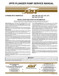
Pump service manual for 1DX, 2DX, 3DX, 3DNX, 3SP ... - Cat Pumps
Pump service manual for 1DX, 2DX, 3DX, 3DNX, 3SP ... - Cat Pumps
Pump service manual for 1DX, 2DX, 3DX, 3DNX, 3SP ... - Cat Pumps

Create successful ePaper yourself
Turn your PDF publications into a flip-book with our unique Google optimized e-Paper software.
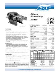
PREVENTATIVE MAINTENANCE CHECK-LIST<br />
Check Daily Weekly 50 hrs. 500 hrs.* 1000 hrs.**<br />
Clean Filters x<br />
Oil Level/Quality x<br />
Oil Leaks x<br />
Water Leaks x<br />
Plumbing x<br />
Initial Oil Change x<br />
Oil Change x<br />
Seal Change x<br />
Valve Change x<br />
Accessories x<br />
* If other than CAT PUMPS special custom blend, multi-viscosity ISO68 hydraulic<br />
oil is used, change cycle should be every 300 hours.<br />
** Each system’s maintenance cycle will be exclusive. If system per<strong>for</strong>mance<br />
decreases, check immediately. If no wear at 1000 hours, check again at<br />
1500 hours and each 500 hours until wear is observed. Valves typically<br />
require changing every other seal change.<br />
Duty cycle, temperature, quality of pumped liquid and inlet feed conditions all<br />
effect the life of pump wear parts and <strong>service</strong> cycle.<br />
** Remember to <strong>service</strong> the regulator/unloader at each seal servicing and check<br />
all system accessories and connections be<strong>for</strong>e resuming operation.<br />
TORQUE CHART<br />
Torque<br />
<strong>Pump</strong> Item Thread Tool Size [P/N] in.lbs. ft.lbs. Nm<br />
Plunger Retainer M6 M10 Hex [25082] 55 4.6 6.2<br />
Manifold Head Screws<br />
Valve Plugs<br />
M6 M5 Allen 55 4.6 6.2<br />
<strong>1DX</strong>.MIST, <strong>2DX</strong>, <strong>2DX</strong>.MIST, M20 M19 Hex 520 43 58<br />
<strong>3DX</strong>, <strong>3DNX</strong>, <strong>3SP</strong>, <strong>3SP</strong>X M22 M24 Hex [44046] 870 72.5 98<br />
Bearing Cover Screws M6 M10 Hex [25082] 50 4.0 5.4<br />
Bubble Oil Gauge M28 Oil Gauge Tool [44050] 45 3.6 5<br />
TECHNICAL BULLETIN REFERENCE CHART<br />
No. Subject Models<br />
002 Inlet Pressure VS Liquid Temperature All Models<br />
024 Lubrication of Lo-Pressure Seals All Models<br />
036 Cylinder and Plunger Reference Chart All Models<br />
043 LPS and HPS Servicing All Plunger Models<br />
055 Removing <strong>Pump</strong>s from Gas Engine or Electric Motor <strong>1DX</strong>, 2SF, 2SFX, 2X, <strong>2DX</strong>, <strong>3DX</strong>,<br />
<strong>3DNX</strong>, <strong>3SP</strong>, <strong>3SP</strong>X, 4SF, 4HP, 5DX,<br />
6DX, 66DX<br />
074 Torque Chart Piston and Plunger <strong>Pump</strong>s<br />
083 Winterizing a <strong>Pump</strong> All Models<br />
086 Ceramic Plunger <strong>2DX</strong><br />
094 Modular Unloader Valve and Seat <strong>2DX</strong> and <strong>3DX</strong><br />
INLET CONDITION CHECK-LIST<br />
Review Be<strong>for</strong>e Start-Up<br />
Inadequate inlet conditions can cause serious malfunctions in the best<br />
designed pump. Surprisingly, the simplest of things can cause the<br />
most severe problems or go unnoticed to the unfamiliar or untrained<br />
eye. REVIEW THIS CHECK-LIST BEFORE OPERATION OF ANY<br />
SYSTEM. Remember, no two systems are alike, so there can be no<br />
ONE best way to set-up a system. All factors must be carefully considered.<br />
INLET SUPPLY should exceed the maximum flow being delivered by the<br />
pump to assure proper per<strong>for</strong>mance.<br />
❏ Open inlet shut-off valve and turn on water supply to avoid starving the<br />
pump. DO NOT RUN PUMP DRY.<br />
❏ Temperatures above 130°F are permissible. Add 1/2 PSI inlet pressure per<br />
each degree F over 130°F. Elastomer or RPM changes may be required.<br />
See Tech Bulletin 002 or call CAT PUMPS <strong>for</strong> recommendations.<br />
❏ Avoid closed loop systems especially with high temperature or ultra-high<br />
pressure. Conditions vary with regulating/unloader valve.<br />
❏ Higher temperature liquids tend to vaporize and require positive heads.<br />
❏ When using an inlet supply reservoir, size it to provide adequate<br />
liquid to accommodate the maximum output of the pump, generally a<br />
minimum of 6-10 times the GPM (however, a combination of system<br />
factors can change this requirement); provide adequate baffling in the<br />
tank to eliminate air bubbles and turbulence; install diffusers on all<br />
return lines to the tank.<br />
INLET LINE SIZE should be adequate to avoid starving the pump.<br />
❏ Line size must be a minimum of one size larger than the pump inlet<br />
fitting. Avoid tees, 90 degree elbows or valves in the inlet line of the<br />
pump to reduce the risk of flow restriction and cavitation.<br />
❏ The line MUST be a FLEXIBLE hose, NOT a rigid pipe, and rein<strong>for</strong>ced<br />
on SUCTION systems to avoid collapsing.<br />
❏ The simpler the inlet plumbing the less the potential <strong>for</strong> problems. Keep<br />
the length to a minimum, the number of elbows and joints to a minimum<br />
(ideally no elbows) and the inlet accessories to a minimum.<br />
❏ Use pipe sealant to assure air-tight, positive sealing pipe joints.<br />
INLET PRESSURE should fall within the specifications of the pump.<br />
❏ Acceleration loss of liquids may be increased by high RPM, high<br />
temperatures, low vapor pressures or high viscosity and may require a<br />
pressurized inlet to maintain adequate inlet supply.<br />
❏ Optimum pump per<strong>for</strong>mance is obtained with +20 PSI (1.4 BAR) inlet<br />
pressure. With adequate inlet plumbing, most pumps will per<strong>for</strong>m with<br />
flooded suction. Maximum inlet pressure is 60 PSI (4 BAR).<br />
❏ After prolonged storage, pump should be rotated by hand and purged<br />
of air to facilitate priming. Disconnect the discharge port and allow liquid<br />
to pass through pump and measure flow.<br />
INLET ACCESSORIES are designed to protect against over pressurization,<br />
control inlet flow, contamination or temperature and provide ease of<br />
servicing.<br />
❏ A shut-off valve is recommended to facilitate maintenance.<br />
❏ A stand pipe can be used in some applications to help maintain a<br />
positive head at the pump inlet line.<br />
❏ Inspect and clean inlet filters on a regular schedule to avoid flow restriction.<br />
❏ A pressure transducer is necessary to accurately read inlet pressure.<br />
Short term, intermittent cavitation will not register on a standard<br />
gauge.<br />
❏ All accessories should be sized to avoid restricting the inlet flow.<br />
❏ All accessories should be compatible with the solution being pumped to<br />
prevent premature failure or malfunction.<br />
BY-PASS TO INLET Care should be exercised when deciding the method<br />
of by-pass from control valves.<br />
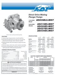
❏ The <strong>2DX</strong>, <strong>3DX</strong>, <strong>3DNX</strong> and <strong>3SP</strong>X pumps come with a Integral Unloader<br />
with built-in by-pass to route by-pass liquid back to the pump inlet. The<br />
<strong>3SP</strong> pumps come with a Regulating Unloader and rein<strong>for</strong>ced, flexible<br />
hose rated up to 300 PSI. No additional by-pass hose is required. The<br />
<strong>1DX</strong>.MIST and <strong>2DX</strong>.MIST pumps come with a Integral Regulator.