Pump service manual for 1DX, 2DX, 3DX, 3DNX, 3SP ... - Cat Pumps
Pump service manual for 1DX, 2DX, 3DX, 3DNX, 3SP ... - Cat Pumps
Pump service manual for 1DX, 2DX, 3DX, 3DNX, 3SP ... - Cat Pumps

You also want an ePaper? Increase the reach of your titles
YUMPU automatically turns print PDFs into web optimized ePapers that Google loves.
<strong>1DX</strong>, <strong>2DX</strong>, <strong>3DX</strong>, <strong>3DNX</strong>, <strong>3SP</strong>, <strong>3SP</strong>X PLUNGER PUMP SERVICE MANUAL<br />
<strong>1DX</strong> MODELS: <strong>1DX</strong>015ELS.MIST, <strong>1DX</strong>03ELS.MIST<br />
<strong>2DX</strong> MODELS: <strong>2DX</strong>20ES, <strong>2DX</strong>27GS, <strong>2DX</strong>30GS<br />
<strong>2DX</strong>05ELS.MIST, <strong>2DX</strong>15ES.MIST,<br />
<strong>2DX</strong>20ES.MIST, <strong>2DX</strong>27ES.MIST<br />
<strong>2DX</strong>30ES.MIST<br />
SPECIFICATIONS: Maximum specifications refer to individual attributes. It is<br />
not implied that all maximums can be per<strong>for</strong>med simultaneously. If more<br />
than one maximum is considered, check with your CAT PUMPS supplier to<br />
confirm the proper per<strong>for</strong>mance and pump selection. Refer to individual Data<br />
Sheets <strong>for</strong> complete specifications, parts list and exploded view.<br />
LUBRICATION: Fill crankcase with special CAT PUMP Hydraulic oil per pump<br />
specifications [<strong>1DX</strong>, <strong>2DX</strong>, <strong>3DX</strong>, <strong>3DNX</strong>-8.5 oz., <strong>3SP</strong>, <strong>3SP</strong>X-10.15 oz.]. DO NOT<br />
RUN PUMP WITHOUT OIL IN CRANKCASE. Change initial fill after 50 hours<br />
running period. Thereafter, change oil every 3 months or 500 hour intervals.<br />
DRIVE SELECTION: The pump shaft size is 5/8" hollow shaft on “ES” and<br />
“ELS” models, 3/4" hollow shaft on “GEI” and “GS” models, 1" hollow shaft on<br />
“G1I” models. The motor or engine driving the pump must be of adequate<br />
horsepower to maintain full RPM when the pump is under load. Select the<br />
horsepower requirement according to required pump discharge flow and maximum<br />
pressure at the pump! Consult the manufacturer of gas or diesel engine<br />
<strong>for</strong> proper selection.<br />
MOUNTING: <strong>1DX</strong>, <strong>2DX</strong>, <strong>3DX</strong>, <strong>3DNX</strong>, <strong>3SP</strong> and <strong>3SP</strong>X models are direct drive.<br />
The <strong>1DX</strong>.MIST and <strong>2DX</strong>.MIST electric models can be mounted directly to a<br />
C-Face motor; the <strong>3SP</strong>35GEI and <strong>3SP</strong>X35GEI models come with an adapter<br />
plate to mount to a C-Face motor. The gas model comes with an adapter plate<br />
that mounts to a gas engine. Be<strong>for</strong>e mounting pump to electric motor or gas<br />
engine, apply PN 6106 antiseize lubricant to pump shaft. Refer to Technical<br />
Bulletin 055 <strong>for</strong> instructions on removing pump from electric motor or gas<br />
engine. To minimize piping stress, use appropriate flexible hose to inlet and<br />
discharge ports.<br />
LOCATION: If the pump is used in extremely dirty or humid conditions, it is<br />
recommended pump be enclosed. Do not store or operate in excessively high<br />
temperature areas or enclosed without proper ventilation. Temperatures above<br />
130°F are permissible. Add 1/2 PSI inlet pressure per each degree F over<br />
130°F. Elastomer or RPM changes may be required. See Tech Bulletin 002 or<br />
call CAT PUMPS <strong>for</strong> recommendations.<br />
INLET CONDITIONS: Refer to complete Inlet Condition Check-List in this<br />
<strong>manual</strong> be<strong>for</strong>e starting system. DO NOT STARVE THE PUMP OR RUN DRY.<br />
®<br />
<strong>3DX</strong> MODELS: <strong>3DX</strong>25GSI, <strong>3DX</strong>27GSI, <strong>3DX</strong>29GSI,<br />
<strong>3DX</strong>30GSI<br />
<strong>3DNX</strong> MODELS: <strong>3DNX</strong>25GSI, <strong>3DNX</strong>27GSI<br />
<strong>3SP</strong> MODELS: <strong>3SP</strong>30G1I, <strong>3SP</strong>35GEI<br />
<strong>3SP</strong>X MODELS: <strong>3SP</strong>X30G1I, <strong>3SP</strong>X35GEI<br />
INSTALLATION AND START-UP INFORMATION<br />
Optimum per<strong>for</strong>mance of the pump is dependent upon the entire liquid system and will be obtained only<br />
with the proper selection, installation of plumbing, and operation of the pump and accessories.<br />
DISCHARGE CONDITIONS: OPEN ALL VALVES BEFORE STARTING<br />
SYSTEM to avoid deadhead overpressure condition and severe damage to the<br />
pump or system.<br />
A reliable Pressure Gauge should be installed near the discharge outlet of the<br />
high pressure manifold. This is extremely important <strong>for</strong> adjusting pressure<br />
regulating devices and also <strong>for</strong> proper sizing of the nozzle or restricting orifice.<br />
The pump is rated <strong>for</strong> a maximum pressure; this is the pressure that is read at<br />
the discharge manifold of the pump, NOT AT THE GUN OR NOZZLE.<br />
Use PTFE thread tape or pipe thread sealant (sparingly) to connect accessories<br />
or plumbing. Exercise caution not to wrap tape beyond the last thread to avoid<br />
tape from becoming lodged in the pump or accessories. This condition will<br />
cause a malfunction of the pump or system.<br />
PRESSURE REGULATION: All systems require both a primary pressure<br />
regulating device (i.e., regulator, unloader) and a secondary pressure safety<br />
relief device (i.e., pop-off valve, safety valve). The primary pressure device<br />
must be installed on the discharge side of the pump. The function of the primary<br />
pressure regulating device is to protect the pump from over pressurization,<br />
which can be caused by a plugged or closed off discharge line. Over pressurization<br />
can severely damage the pump, other system components and can<br />
cause bodily harm. The secondary safety relief device must be installed<br />
in-line between the primary device and pump or on the opposite side of the<br />
manifold head. This will ensure pressure relief of the system if the primary<br />
regulating device fails. Failure to install such a safely device will void the warranty<br />
on the pump.<br />
NOZZLES: A worn nozzle will result in loss of pressure. Do not adjust pressure<br />
regulating device to compensate. Replace nozzle and reset regulating device<br />
to system pressure.<br />
PUMPED LIQUIDS: Some liquids may require a flush between operations<br />
or be<strong>for</strong>e storing. For pumping liquids other than water, contact your CAT<br />
PUMPS supplier.<br />
STORING: For extended storing or between use in cold climates, drain all<br />
pumped liquids from pump and flush with antifreeze solution to prevent<br />
freezing and damage to the pump. DO NOT RUN PUMP WITH FROZEN<br />
LIQUID (refer to Tech Bulletin 083).<br />
WARNING<br />
All systems require both a primary pressure regulating device (i.e., regulator, unloader) and a secondary pressure safety relief device (i.e., pop-off valve, safety valve).<br />
Failure to install such relief devices could result in personal injury or damage to the pump or to system components. CAT PUMPS does not assume any liability or responsibility<br />
<strong>for</strong> the operation of a customer’s high pressure system.<br />
World Headquarters<br />
CAT PUMPS<br />
1681 - 94th Lane N.E. Minneapolis, MN 55449-4324<br />
Phone (763) 780-5440 — FAX (763) 780-2958<br />
e-mail: techsupport@catpumps.com<br />
www.catpumps.com<br />
International Inquiries<br />
FAX (763) 785-4329<br />
e-mail: intlsales@catpumps.com<br />
®<br />
The <strong>Pump</strong>s with Nine Lives<br />
CAT PUMPS (U.K.) LTD.<br />
1 Fleet Business Park, Sandy Lane, Church Crookham<br />
FLEET, Hampshire, GU52 8BF, England<br />
Phone Fleet 44 1252-622031 — Fax 44 1252-626655<br />
e-mail: sales@catpumps.co.uk<br />
N.V. CAT PUMPS INTERNATIONAL S.A.<br />
Heiveldekens 6A, B-2550 Kontich, Belgium<br />
Phone 32-3-450.71.50 — Fax 32-3-450.71.51<br />
e-mail: cpi@catpumps.be www.catpumps.be<br />
CAT PUMPS DEUTSCHLAND GmbH<br />
Buchwiese 2, D-65510 Idstein, Germany<br />
Phone 49 6126-9303 0 — Fax 49 6126-9303 33<br />
e-mail: catpumps@t-online.de www.catpumps.de<br />
PN 30263 Rev C 11709
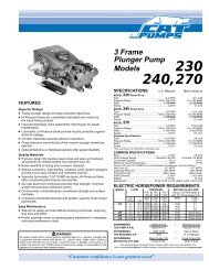
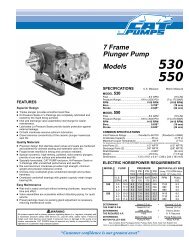
All <strong>1DX</strong>.MIST, <strong>2DX</strong>, <strong>2DX</strong>.MIST and <strong>3DX</strong> Models<br />
Discharge and Inlet Valve Assembly - Stacked Valve design<br />
SERVICING THE VALVES<br />
Disassembly<br />
NOTE: All pump models require one (1) stacked valve<br />
kit to repair pump. Models <strong>2DX</strong>, <strong>2DX</strong>.MIST, <strong>3DX</strong>, <strong>3DNX</strong>,<br />
<strong>3SP</strong> and <strong>3SP</strong>X contain three complete valve assemblies<br />
(inlet and discharge). Whereas, model <strong>1DX</strong>03ELS.MIST<br />
contains two complete valve assemblies and model<br />
<strong>1DX</strong>015ELS.MIST contains one complete valve assembly.<br />
NOTE: Discharge and inlet valve assemblies may stay<br />
together or separate during removal.<br />
NOTE: Spring retainer may also separate from the seat<br />
during removal.<br />
1. Models <strong>1DX</strong>.MIST, <strong>2DX</strong>, <strong>2DX</strong>.MIST and <strong>3DX</strong>: Use a M19<br />
Hex tool to remove valve plugs on top of manifold.<br />
Models <strong>3DNX</strong>, <strong>3SP</strong> and <strong>3SP</strong>X: Use a M24 Hex tool to<br />
remove valve plugs on top of manifold.<br />
2. Use a reverse pliers to remove stacked valve assemblies<br />
from the valve chamber.<br />
3. If the discharge valve assembly separates from the inlet<br />
valve assembly, use a reverse pliers to remove it from the<br />
valve chamber.<br />
CAUTION: Exercise caution as the reverse pliers may<br />
damage the threads in valve chamber or spring retainer.<br />
4. Models <strong>1DX</strong>.MIST, <strong>2DX</strong>, <strong>2DX</strong>.MIST and <strong>3DX</strong>: The spring<br />
retainer may separate from the seat. Remove the spring<br />
and valve from the valve chamber. Thread an M8 screw<br />
into the seat and remove from valve chamber.<br />
5. Models <strong>1DX</strong>.MIST, <strong>2DX</strong>, <strong>2DX</strong>.MIST and <strong>3DX</strong>: Separate<br />
valve assembly by using the same M8 screw and thread<br />
into bottom of seat until screw contacts bottom of valve.<br />
Continue threading in screw until spring retainer separates<br />
from seat.<br />
Models <strong>3DNX</strong>, <strong>3SP</strong> and <strong>3SP</strong>X: Separate valve assembly<br />
by inserting screwdriver into spring retainer and press the<br />
backside of valve until seat separates from the spring<br />
retainer.<br />
6. Remove o-ring from each seat and valve plug.<br />
<strong>3SP</strong>30G1I, <strong>3SP</strong>35GEI, <strong>3SP</strong>X30G1I, <strong>3SP</strong>X35GEI<br />
Discharge and Inlet Valve Assembly - Stacked Valve design<br />
CAUTION: Be<strong>for</strong>e commencing with <strong>service</strong>, shut off drive (electric motor, gas or diesel engine) and turn off water supply to pump. Relieve all discharge<br />
line pressure by triggering gun or opening valve in discharge line.<br />
After servicing is completed, turn on water supply to pump, start drive, reset pressure regulating device and secondary valve, read system pressure on<br />
the gauge at the pump head. Check <strong>for</strong> any leaks, vibration or pressure fluctuations and resume operation.<br />
Inspect and <strong>service</strong> all system accessories on the same schedule as your pump.<br />
Reassembly<br />
1. Examine spring retainers <strong>for</strong> internal wear or breaks in the<br />
structure and replace as needed.<br />
2. Examine springs <strong>for</strong> fatigue or breaks and replace as needed.<br />
3. Examine valves and seats <strong>for</strong> grooves, pitting or wear and<br />
replace as needed.<br />
4. Examine seat and valve plug o-rings <strong>for</strong> cuts or wear and<br />
replace as needed.<br />
NOTE: Inlet valve seat and o-ring are different from discharge<br />
valve seat and o-ring. One valve kit required per<br />
pump.<br />
5. Models <strong>1DX</strong>.MIST, <strong>2DX</strong>, <strong>2DX</strong>.MIST and <strong>3DX</strong>: Lubricate<br />
and install new o-ring onto large outside diameter of discharge<br />
seat.<br />
Models <strong>3DNX</strong>, <strong>3SP</strong> and <strong>3SP</strong>X: Lubricate and install backup-ring,<br />
and then o-ring onto large outside diameter of discharge<br />
seat.<br />
6. Place seat on work surface with small diameter side up.<br />
7. Place valve onto seat with concave side down.<br />
8. Place spring on valve.<br />
9. Install spring retainer with deep stepped end over spring<br />
and snap onto seat.<br />
NOTE: Repeat steps 6-9 <strong>for</strong> inlet valve assembly.<br />
10. Snap discharge valve assembly onto the inlet valve<br />
assembly and press into valve chamber until completely<br />
seated.<br />
11. Lubricate and install new o-ring onto each valve plug.<br />
12. Apply Loctite® 242® to threads of each valve plug and<br />
thread in hand tight. Torque to specifications per chart.
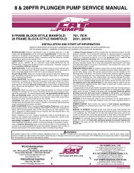
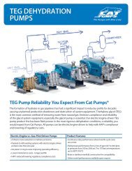
All <strong>1DX</strong>.MIST, <strong>2DX</strong>, <strong>2DX</strong>.MIST and <strong>3DX</strong> Models<br />
Lo-Pressure and Hi-Pressure Seals with Seal Case<br />
SERVICING THE SEALS<br />
Disassembly<br />
NOTE: All pump models require one (1) seal kit to repair<br />
pump. Models <strong>2DX</strong>, <strong>2DX</strong>.MIST, <strong>3DX</strong>, <strong>3DNX</strong>, <strong>3SP</strong> and<br />
<strong>3SP</strong>X contain (3) high pressure seals, (3) low pressure<br />
seals, (3) seal washers and (3) o-rings. Whereas, model<br />
<strong>1DX</strong>03ELS.MIST contains (2) high pressure seals, (2) low<br />
pressure seals, (2) seal washers and (2) o-rings. The<br />
model <strong>1DX</strong>015ELS.MIST contains (1) high pressure seal,<br />
(1) low pressure seal, (1) seal washer and (1) o-ring.<br />
1. Using an M5 allen wrench, remove the hex socket head<br />
(HSH) screws from the face of the manifold head.<br />
2. Insert flat head screwdrivers on each side between the<br />
crankcase and manifold head. Gently apply pressure to the<br />
head to begin separation.<br />
3. Support the manifold head from the underside and pull the<br />
manifold head away from the crankcase.<br />
CAUTION: Keep the manifold head properly aligned with<br />
the ceramic plungers when removing to avoid damage to<br />
the plungers.<br />
NOTE: The seal case may stay in the manifold or on the<br />
ceramic plungers.<br />
4. Place manifold head on work surface with crankcase side up.<br />
5. Remove seal retainer from each plunger rod.<br />
6. Use a screwdriver to pry out the Lo-Pressure seal from<br />
each seal case.<br />
CAUTION: Screwdriver may damage seal during removal.<br />
7. Use reverse pliers to remove seal case from each seal<br />
chamber.<br />
NOTE: Insert the reverse pliers into the second lip to avoid<br />
damage to the seal case.<br />
8. Carefully insert a small screwdriver under the o-ring and<br />
roll the o-ring off each seal case.<br />
CAUTION: Exercise caution as the screwdriver may score<br />
o-ring sealing surface.<br />
9. Models <strong>1DX</strong>.MIST, <strong>2DX</strong>, <strong>2DX</strong>.MIST and <strong>3DX</strong>: The Hi-<br />
Pressure seals can be easily removed from each seal<br />
chamber by hand or with reverse pliers.<br />
Models <strong>3DNX</strong>, <strong>3SP</strong> and <strong>3SP</strong>X: Remove V-Packing and<br />
male adapter from each seal chamber by hand or with a<br />
reverse pliers.<br />
<strong>3SP</strong>30G1I, <strong>3SP</strong>35GEI, <strong>3SP</strong>X30G1I, <strong>3SP</strong>X35G1I<br />
Lo-Pressure Seal, V-Packing, Male Adapter and Seal Case<br />
Reassembly<br />
1. Examine the manifold chamber walls <strong>for</strong> scale buildup or<br />
damage.<br />
2. Examine Hi-Pressure seals or V-Packings <strong>for</strong> frayed<br />
edges or uneven wear and replace as needed.<br />
3. Examine seal case o-rings <strong>for</strong> cuts or deterioration and<br />
replace as needed.<br />
4. Examine Lo-Pressure seals <strong>for</strong> wear to the internal ridges,<br />
outer surfaces <strong>for</strong> broken springs and replace as needed.<br />
NOTE: Seals and o-rings are available in seal kits.<br />
5 Examine seal retainers <strong>for</strong> de<strong>for</strong>mation and replace as<br />
needed.<br />
6. Models <strong>1DX</strong>.MIST, <strong>2DX</strong>, <strong>2DX</strong>.MIST and <strong>3DX</strong>: Lubricate<br />
and install new Hi-Pressure seal by hand into each seal<br />
chamber with the grooved side down.<br />
Models <strong>3DNX</strong>, <strong>3SP</strong> and <strong>3SP</strong>X: Install male adapter with<br />
notch side down. Lubricate and install new V-Packing by<br />
hand into seal chamber with grooved side down.<br />
7. Lubricate and install o-ring on each seal case. Press small<br />
end of seal case into each seal chamber.<br />
8. Press new Lo-Pressure seal into each seal case with the<br />
garter spring down.<br />
9. Examine ceramic plunger <strong>for</strong> cracks or scale buildup and<br />
proceed to SERVICING THE PLUNGERS if worn.<br />
10. Models <strong>1DX</strong>.MIST, <strong>2DX</strong>, <strong>2DX</strong>.MIST and <strong>3DX</strong>: Slide seal<br />
retainer over each ceramic plunger with the drain slots facing<br />
the crankcase and the openings to the top and bottom.<br />
Press into the crankcase.<br />
Models <strong>3DNX</strong>, <strong>3SP</strong> and <strong>3SP</strong>X: Slide seal retainer over<br />
each ceramic plunger with the tabs facing out. Press into<br />
the crankcase.<br />
11. Rotate crankshaft by hand so the two outside plungers are<br />
extended equally.<br />
12. Lightly lubricate ceramic plungers, then carefully slide the<br />
manifold head over the ceramic plungers, supporting it<br />
from the underside to avoid damage to the plungers or<br />
seals. Press the manifold head up to the crankcase until<br />
flush.<br />
13. Thread HSH screws in hand tight. Torque in sequence to<br />
specifications in torque chart.
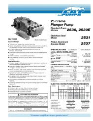
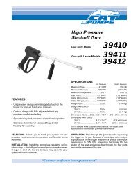
All <strong>1DX</strong>.MIST, <strong>2DX</strong>, <strong>2DX</strong>.MIST, <strong>3DX</strong>, <strong>3DNX</strong> and <strong>3SP</strong>X Models<br />
Plunger Arrangement<br />
SERVICING THE PLUNGERS<br />
Disassembly<br />
1. To <strong>service</strong> the ceramic plungers, it is necessary to remove<br />
the manifold head. See SERVICING THE SEALS,<br />
Disassembly, steps 1-3.<br />
2. Remove seal retainer from each plunger rod.<br />
3. Using a M10 Hex tool, loosen the plunger retainer on each<br />
plunger rod approximately three to four turns.<br />
4. Push the ceramic plunger back towards the crankcase to<br />
separate from the plunger retainer and proceed with<br />
unthreading the plunger retainer by hand.<br />
5. Models <strong>1DX</strong>.MIST, <strong>2DX</strong>, <strong>2DX</strong>.MIST, <strong>3DX</strong>, <strong>3DNX</strong> and <strong>3SP</strong>X:<br />
Remove the ceramic plunger and seal washer from each<br />
plunger retainer.<br />
Model <strong>3SP</strong>: Remove the ceramic plunger and copper<br />
retainer gasket from each plunger retainer.<br />
NOTE: Copper plunger retainer gasket has been replaced<br />
by NBR seal washer.<br />
Reassembly<br />
1. Visually inspect the crankcase oil seals <strong>for</strong> deterioration or<br />
leaks. Contact CAT PUMPS <strong>for</strong> assistance with replacement.<br />
See SERVICING THE CRANKCASE.<br />
2. Examine seal washers and replace if cut or worn.<br />
3. Examine plunger retainers <strong>for</strong> damaged threads and<br />
replace as needed.<br />
4. Install new seal washer onto each plunger retainer.<br />
5. Examine the ceramic plungers <strong>for</strong> scoring, scale buildup,<br />
chips or cracks and replace as needed. The ceramic plungers<br />
do not need to be replaced with every seal servicing.<br />
6. Slide plunger retainer with seal washer into flat end of<br />
ceramic plunger.<br />
7. Apply Loctite® 242® to exposed threaded end of plunger<br />
retainer.<br />
8. Install ceramic plunger with plunger retainer and seal<br />
washer over each plunger rod shoulder and thread hand<br />
tight. Torque to specifications per chart.<br />
NOTE: Ceramic Plungers can only be installed in one<br />
direction. Counterbore end of ceramic plunger fits over<br />
lunger rod shoulder.<br />
9. See SERVICING THE SEALS, Reassembly, steps 10-13.<br />
<strong>3SP</strong>30G1I, <strong>3SP</strong>35GEI<br />
Plunger Arrangement<br />
TORQUE SEQUENCE<br />
7 1 3 5<br />
6 4 2 8<br />
SERVICING THE CRANKCASE<br />
1. While manifold, plungers and retainers are removed,<br />
examine crankcase oil seals <strong>for</strong> leaking and wear.<br />
2. Check <strong>for</strong> any signs of leaking at bearing cover, drain plug<br />
or bubble gauge.<br />
3. Check oil level and <strong>for</strong> evidence of water in oil. Change<br />
crankcase oil on a regular schedule. See PREVENTATIVE<br />
MAINTENANCE CHECK-LIST.<br />
4. Rotate crankshaft by hand to feel <strong>for</strong> smooth bearing<br />
movement.<br />
5. Examine crankshaft oil seal externally <strong>for</strong> drying, cracking<br />
or leaking.<br />
6. Contact CAT PUMPS or local distributor if crankcase <strong>service</strong><br />
is required.
SERVICING THE UNLOADER AND REGULATOR<br />
<strong>1DX</strong>015ELS.MIST, <strong>1DX</strong>03ELS.MIST - Integral Regulator<br />
<strong>2DX</strong>, <strong>3DX</strong>, <strong>3DNX</strong>, <strong>3SP</strong>X - Integral Unloader<br />
<strong>2DX</strong>.MIST - Integral Regulator<br />
<strong>3SP</strong> - 7700 Modular Unloader (refer to individual data sheet)<br />
Disassembly<br />
NOTE: On models <strong>3SP</strong>30G1I, <strong>3SP</strong>35G1I, <strong>3SP</strong>X30G1I<br />
and <strong>3SP</strong>X35GEI remove black adjusting handle.<br />
1. Remove brass adjusting cap by turning in a counterclockwise<br />
direction.<br />
2. Remove exposed coil spring and flat spring retainer.<br />
3. Use an M19 wrench to remove piston retainer by turning<br />
in a counterclockwise direction.<br />
NOTE: The piston stem and valve assembly may fall out<br />
when the piston retainer is removed. If so, proceed to step<br />
6., if not, continue with step 4.<br />
4. Use a needle nose pliers to remove piston stem and valve<br />
assembly.<br />
5. Separate piston stem from valve. Secure the valve near<br />
the valve retainer. Insert a screwdriver into slotted head of<br />
piston stem and unthread from valve.<br />
CAUTION: Exercise extreme caution to avoid contact and<br />
damage to the tapered surface of valve.<br />
6. Examine seat at the bottom of the unloader chamber <strong>for</strong><br />
grooves, pitting or wear, replace only as needed.<br />
CAUTION: Seat will be damaged when removed.<br />
Reassembly<br />
1. If seat is worn or damaged, press new seat into unloader<br />
chamber until squarely seated.<br />
2. Examine piston stem, washer, valve retainer and valve <strong>for</strong><br />
grooves, pitting or wear and replace as needed. Examine<br />
o-rings and back-up ring <strong>for</strong> cuts or wear and replace as<br />
needed.<br />
3. Lubricate and install o-ring over slotted head of piston<br />
stem, then position back-up ring on top of o-ring.<br />
4. Lubricate and install o-rings on valve retainer.<br />
5. Install washer and then valve retainer with o-rings onto<br />
piston stem. Apply Loctite® 242® to threads of piston<br />
stem and screw valve onto piston stem.<br />
6. Lower complete piston stem and valve assembly into<br />
unloader chamber with valve facing downward.<br />
7. Examine piston retainer <strong>for</strong> damaged threads or wear and<br />
replace as needed. Examine o-ring <strong>for</strong> cuts or wear and<br />
replace as needed.<br />
8. Apply Loctite® 242® to threads and then hand thread piston<br />
retainer into unloader by turning in a clockwise direction,<br />
and then tighten with wrench.<br />
9. Examine spring retainer and coil spring <strong>for</strong> fatigue or<br />
breaks and replace as needed.<br />
10. Place spring retainer into piston retainer, followed by coil<br />
spring.<br />
11. Thread brass adjusting cap onto piston retainer by turning<br />
in a clockwise direction.<br />
Loctite and 242 are registered trademarks of Henkel Corporation.
PREVENTATIVE MAINTENANCE CHECK-LIST<br />
Check Daily Weekly 50 hrs. 500 hrs.* 1000 hrs.**<br />
Clean Filters x<br />
Oil Level/Quality x<br />
Oil Leaks x<br />
Water Leaks x<br />
Plumbing x<br />
Initial Oil Change x<br />
Oil Change x<br />
Seal Change x<br />
Valve Change x<br />
Accessories x<br />
* If other than CAT PUMPS special custom blend, multi-viscosity ISO68 hydraulic<br />
oil is used, change cycle should be every 300 hours.<br />
** Each system’s maintenance cycle will be exclusive. If system per<strong>for</strong>mance<br />
decreases, check immediately. If no wear at 1000 hours, check again at<br />
1500 hours and each 500 hours until wear is observed. Valves typically<br />
require changing every other seal change.<br />
Duty cycle, temperature, quality of pumped liquid and inlet feed conditions all<br />
effect the life of pump wear parts and <strong>service</strong> cycle.<br />
** Remember to <strong>service</strong> the regulator/unloader at each seal servicing and check<br />
all system accessories and connections be<strong>for</strong>e resuming operation.<br />
TORQUE CHART<br />
Torque<br />
<strong>Pump</strong> Item Thread Tool Size [P/N] in.lbs. ft.lbs. Nm<br />
Plunger Retainer M6 M10 Hex [25082] 55 4.6 6.2<br />
Manifold Head Screws<br />
Valve Plugs<br />
M6 M5 Allen 55 4.6 6.2<br />
<strong>1DX</strong>.MIST, <strong>2DX</strong>, <strong>2DX</strong>.MIST, M20 M19 Hex 520 43 58<br />
<strong>3DX</strong>, <strong>3DNX</strong>, <strong>3SP</strong>, <strong>3SP</strong>X M22 M24 Hex [44046] 870 72.5 98<br />
Bearing Cover Screws M6 M10 Hex [25082] 50 4.0 5.4<br />
Bubble Oil Gauge M28 Oil Gauge Tool [44050] 45 3.6 5<br />
TECHNICAL BULLETIN REFERENCE CHART<br />
No. Subject Models<br />
002 Inlet Pressure VS Liquid Temperature All Models<br />
024 Lubrication of Lo-Pressure Seals All Models<br />
036 Cylinder and Plunger Reference Chart All Models<br />
043 LPS and HPS Servicing All Plunger Models<br />
055 Removing <strong>Pump</strong>s from Gas Engine or Electric Motor <strong>1DX</strong>, 2SF, 2SFX, 2X, <strong>2DX</strong>, <strong>3DX</strong>,<br />
<strong>3DNX</strong>, <strong>3SP</strong>, <strong>3SP</strong>X, 4SF, 4HP, 5DX,<br />
6DX, 66DX<br />
074 Torque Chart Piston and Plunger <strong>Pump</strong>s<br />
083 Winterizing a <strong>Pump</strong> All Models<br />
086 Ceramic Plunger <strong>2DX</strong><br />
094 Modular Unloader Valve and Seat <strong>2DX</strong> and <strong>3DX</strong><br />
INLET CONDITION CHECK-LIST<br />
Review Be<strong>for</strong>e Start-Up<br />
Inadequate inlet conditions can cause serious malfunctions in the best<br />
designed pump. Surprisingly, the simplest of things can cause the<br />
most severe problems or go unnoticed to the unfamiliar or untrained<br />
eye. REVIEW THIS CHECK-LIST BEFORE OPERATION OF ANY<br />
SYSTEM. Remember, no two systems are alike, so there can be no<br />
ONE best way to set-up a system. All factors must be carefully considered.<br />
INLET SUPPLY should exceed the maximum flow being delivered by the<br />
pump to assure proper per<strong>for</strong>mance.<br />
❏ Open inlet shut-off valve and turn on water supply to avoid starving the<br />
pump. DO NOT RUN PUMP DRY.<br />
❏ Temperatures above 130°F are permissible. Add 1/2 PSI inlet pressure per<br />
each degree F over 130°F. Elastomer or RPM changes may be required.<br />
See Tech Bulletin 002 or call CAT PUMPS <strong>for</strong> recommendations.<br />
❏ Avoid closed loop systems especially with high temperature or ultra-high<br />
pressure. Conditions vary with regulating/unloader valve.<br />
❏ Higher temperature liquids tend to vaporize and require positive heads.<br />
❏ When using an inlet supply reservoir, size it to provide adequate<br />
liquid to accommodate the maximum output of the pump, generally a<br />
minimum of 6-10 times the GPM (however, a combination of system<br />
factors can change this requirement); provide adequate baffling in the<br />
tank to eliminate air bubbles and turbulence; install diffusers on all<br />
return lines to the tank.<br />
INLET LINE SIZE should be adequate to avoid starving the pump.<br />
❏ Line size must be a minimum of one size larger than the pump inlet<br />
fitting. Avoid tees, 90 degree elbows or valves in the inlet line of the<br />
pump to reduce the risk of flow restriction and cavitation.<br />
❏ The line MUST be a FLEXIBLE hose, NOT a rigid pipe, and rein<strong>for</strong>ced<br />
on SUCTION systems to avoid collapsing.<br />
❏ The simpler the inlet plumbing the less the potential <strong>for</strong> problems. Keep<br />
the length to a minimum, the number of elbows and joints to a minimum<br />
(ideally no elbows) and the inlet accessories to a minimum.<br />
❏ Use pipe sealant to assure air-tight, positive sealing pipe joints.<br />
INLET PRESSURE should fall within the specifications of the pump.<br />
❏ Acceleration loss of liquids may be increased by high RPM, high<br />
temperatures, low vapor pressures or high viscosity and may require a<br />
pressurized inlet to maintain adequate inlet supply.<br />
❏ Optimum pump per<strong>for</strong>mance is obtained with +20 PSI (1.4 BAR) inlet<br />
pressure. With adequate inlet plumbing, most pumps will per<strong>for</strong>m with<br />
flooded suction. Maximum inlet pressure is 60 PSI (4 BAR).<br />
❏ After prolonged storage, pump should be rotated by hand and purged<br />
of air to facilitate priming. Disconnect the discharge port and allow liquid<br />
to pass through pump and measure flow.<br />
INLET ACCESSORIES are designed to protect against over pressurization,<br />
control inlet flow, contamination or temperature and provide ease of<br />
servicing.<br />
❏ A shut-off valve is recommended to facilitate maintenance.<br />
❏ A stand pipe can be used in some applications to help maintain a<br />
positive head at the pump inlet line.<br />
❏ Inspect and clean inlet filters on a regular schedule to avoid flow restriction.<br />
❏ A pressure transducer is necessary to accurately read inlet pressure.<br />
Short term, intermittent cavitation will not register on a standard<br />
gauge.<br />
❏ All accessories should be sized to avoid restricting the inlet flow.<br />
❏ All accessories should be compatible with the solution being pumped to<br />
prevent premature failure or malfunction.<br />
BY-PASS TO INLET Care should be exercised when deciding the method<br />
of by-pass from control valves.<br />
❏ The <strong>2DX</strong>, <strong>3DX</strong>, <strong>3DNX</strong> and <strong>3SP</strong>X pumps come with a Integral Unloader<br />
with built-in by-pass to route by-pass liquid back to the pump inlet. The<br />
<strong>3SP</strong> pumps come with a Regulating Unloader and rein<strong>for</strong>ced, flexible<br />
hose rated up to 300 PSI. No additional by-pass hose is required. The<br />
<strong>1DX</strong>.MIST and <strong>2DX</strong>.MIST pumps come with a Integral Regulator.
Water*<br />
Flow<br />
Gal/Min<br />
HOSE FRICTION LOSS<br />
PRESSURE DROP IN PSI PER 100 FT OF HOSE<br />
WITH TYPICAL WATER FLOW RATES<br />
Hose Inside Diameters, Inches<br />
1/4 5/16 3/8 1/2 5/8 3/4 1"<br />
0.5 16 5 2<br />
1 54 20 7 2<br />
2 180 60 25 6 2<br />
3 380 120 50 13 4 2<br />
4 220 90 24 7 3<br />
5 320 130 34 10 4<br />
6 220 52 16 7 1<br />
8 300 80 25 10 2<br />
10 450 120 38 14 3<br />
15 900 250 80 30 7<br />
20 1600 400 121 50 12<br />
25 650 200 76 19<br />
30 250 96 24<br />
40 410 162 42<br />
50 600 235 62<br />
60 370 93<br />
*At a fixed flow rate with a given size hose, the pressure drop across a given hose length<br />
will be directly proportional. A 50 ft. hose will exhibit one-half the pressure drop of a 100 ft.<br />
hose. Above values shown are valid at all pressure levels.<br />
Water<br />
GPM<br />
1<br />
2<br />
3<br />
5<br />
8<br />
10<br />
15<br />
25<br />
40<br />
60<br />
80<br />
100<br />
WATER LINE PRESSURE LOSS<br />
PRESSURE DROP IN PSI PER 100 FEET<br />
Steel Pipe—Nominal Dia.<br />
1/4 3/8 1/2 3/4 1 1 1 /4 1 1 /2<br />
8.5 1.9<br />
30 7.0 2.1<br />
60 14 4.5 1.1<br />
150 36 12 2.8<br />
330 86 28 6.7 1.9<br />
520 130 43 10 3.0<br />
270 90 21 6.2 1.6<br />
670 240 56 16 4.2 2.0<br />
66 17 8.0<br />
37 17<br />
52 29<br />
210 107 48<br />
Brass Pipe—Nominal Dia.<br />
1/4 3/8 1/2 3/4 1 11 /4 11 6.0 1.6<br />
20 5.6 1.8<br />
/2<br />
40 11 3.6<br />
100 28 9.0 2.2<br />
220 62 21 5.2 1.6<br />
320 90 30 7.8 2.4<br />
190 62 16 5.0 1.5<br />
470 150 40 12 3.8 1.7<br />
39 11 5.0<br />
23 11<br />
40 19<br />
61 28<br />
Copper Tubing O.D. Type L<br />
1/4 3/8 1/2 5/8 3/4 7/8<br />
120 13 2.9 1.0<br />
400 45 10 3.4 1.3<br />
94 20 6.7 2.6<br />
230 50 17 6.1 3.0<br />
500 120 40 15 6.5<br />
180 56 22 10<br />
120 44 20<br />
330 110 50<br />
550 200 88<br />
RESISTANCE OF VALVES AND FITTINGS<br />
Nominal<br />
Pipe<br />
Size<br />
Inches<br />
Inside<br />
Diameter<br />
Inches<br />
Gate<br />
Valve<br />
Globe<br />
Valve<br />
Angle<br />
Valve<br />
45˚<br />
Elbow<br />
90˚<br />
Elbow<br />
180˚<br />
Close<br />
Ret<br />
Tee<br />
Thru<br />
Run<br />
1/2 0.622 0.41 18.5 9.3 0.78 1.67 3.71 0.93 3.33<br />
3/4 0.824 0.54 24.5 12.3 1.03 2.21 4.90 1.23 4.41<br />
1 1.049 0.69 31.2 15.6 1.31 2.81 6.25 1.56 5.62<br />
11 /4 1.380 0.90 41.0 20.5 1.73 3.70 8.22 2.06 7.40<br />
11 /2 1.610 1.05 48.0 24.0 2.15 4.31 9.59 2.40 8.63<br />
2 2.067 1.35 61.5 30.8 2.59 5.55 12.30 3.08 11.60<br />
2 1 /2 2.469 1.62 73.5 36.8 3.09 6.61 14.70 3.68 13.20<br />
3 3.068 2.01 91.5 45.8 3.84 8.23 18.20 4.57 16.40<br />
4 4.026 2.64 120.0 60.0 5.03 10.80 23.90 6.00 21.60<br />
Arriving at a total line pressure loss, consideration should then be given to<br />
pressure loss created by valves, fittings and elevation of lines.<br />
If a sufficient number of valves and fittings are incorporated in the system to<br />
materially affect the total line loss, add to the total line length, the equivalent<br />
length of line of each valve or fitting.<br />
TYPICAL RESERVOIR TANK<br />
RECOMMENDED 6 TO 10 TIMES SYSTEM CAPACITY<br />
Flexible Hose<br />
to <strong>Pump</strong><br />
FILTER<br />
→<br />
→<br />
MIN. 4"<br />
Equivalent Length of Standard Pipe in Feet<br />
Bypass Line<br />
(from regulator or unloader)<br />
Level Sensing<br />
Device<br />
→<br />
→<br />
MIN. 4"<br />
Minimum<br />
Liquid<br />
Level<br />
→<br />
Tee<br />
Thru<br />
Branch<br />
1.5 x D (Min.)<br />
Minimum Two Baffles<br />
Sealed at Bottom<br />
Supply Line<br />
T (Dia of pipe)<br />
X D<br />
→<br />
→<br />
→<br />
→<br />
Bypass Line<br />
(from regulator or<br />
unloader)<br />
Handy Formulas to Help You<br />
Q. How can I find the RPM needed to get specific GPM<br />
(Gallons Per Minute) I want?<br />
Rated RPM<br />
A. Desired RPM = Desired GPM x<br />
Rated GPM<br />
Q. I have to run my pump at a certain RPM. How do I figure<br />
the GPM I’ll get?<br />
Rated GPM<br />
A. Desired GPM = Desired RPM x<br />
Rated RPM<br />
Q. Is there a simple way to find the approximate horsepower<br />
I’ll need to run the pump?<br />
A. Electric Brake GPM x PSI (Standard 85%<br />
Horsepower Required =<br />
1460 Mech. Efficiency)<br />
Q. What size motor pulley should I use?<br />
<strong>Pump</strong> RPM<br />
A. <strong>Pump</strong> Pulley (Outer Diameter) x<br />
Motor/Engine RPM<br />
Q. How do I calculate the torque <strong>for</strong> my hydraulic drive<br />
system?<br />
A. Torque (ft. lbs.) = 3.6<br />
( )<br />
GPM x PSI<br />
RPM<br />
Avoid Cavitation Damage<br />
One or several of the conditions shown in the chart below may<br />
contribute to cavitation in a system resulting in premature wear,<br />
system downtime and unnecessary operating costs.<br />
CONDITION SOLUTION<br />
Inadequate inlet<br />
● Increase line size to the inlet port or one size<br />
line size larger<br />
Water hammering<br />
● Install C.A.T. Tube<br />
liquid acceleration/<br />
deacceleration<br />
● Move pump closer to liquid supply<br />
Rigid Inlet Plumbing ● Use flexible wire rein<strong>for</strong>ced hose to absorb<br />
pulsation and pressure spikes<br />
Excessive Elbows in<br />
Inlet Plumbing<br />
● Keep elbows to a minimum and less than 90°<br />
Excessive liquid<br />
Temperature<br />
● Use Thermo Valve in bypass line<br />
● Do not exceed pump temperature specifications<br />
● Substitute closed loop with baffled holding tank<br />
● Adequately size tank <strong>for</strong> frequent or high<br />
volume bypass<br />
● Pressure feed high temperature liquids<br />
● Properly ventilate cabinets and rooms<br />
Air Leaks in Plumbing ● Check all connections<br />
● Use PTFE thread tape or pipe thread sealant<br />
Agitation in Supply ● Size tank according to pump output —<br />
Tank Minimum 6-10 times system GPM<br />
● Baffle tank to purge air from liquid and<br />
separate inlet from discharge<br />
(Consult<br />
Engine Mfr.)<br />
High Viscosity Liquids ● Verify viscosity against pump specifications<br />
be<strong>for</strong>e operation<br />
● Elevate liquid temperature enough to reduce<br />
viscosity<br />
● Lower RPM of pump<br />
● Pressure feed pump<br />
● Increase inlet line size<br />
Clogged Filters<br />
● Per<strong>for</strong>m regular maintenance or use clean<br />
filters to monitor build up<br />
● Use adequate mesh size <strong>for</strong> liquid and pump<br />
specifications
DIAGNOSIS AND MAINTENANCE<br />
One of the most important steps in a high pressure system is to establish a regular maintenance program. This will vary slightly with each<br />
system and is determined by various elements such as the duty cycle, the liquid being pumped, the actual specifications vs rated specifications<br />
of the pump, the ambient conditions, the inlet conditions and the accessories in the system. A careful review of the necessary inlet conditions<br />
and protection devices required be<strong>for</strong>e the system is installed will eliminate many potential problems.<br />
CAT PUMPS are very easy pumps to <strong>service</strong> and require far less frequent <strong>service</strong> than most pumps. Typically, only common tools are required,<br />
making in-field <strong>service</strong> convenient, however, there are a few custom tools, special to certain models, that do simplify the process. This <strong>service</strong><br />
<strong>manual</strong> is designed to assist you with the disassembly and reassembly of your pump. The following guide will assist in determining the cause<br />
and remedy to various operating conditions. You can also review our FAQ or SERVICE sections on our WEB SITE <strong>for</strong> more facts or contact CAT<br />
PUMPS directly.<br />
PROBLEM PROBABLE CAUSE SOLUTION<br />
Low pressure •Worn nozzle. •Replace with properly sized nozzle.<br />
•Air leak in inlet plumbing. •Tighten fittings and hoses. Use PTFE liquid or tape.<br />
•Pressure gauge inoperative or not registering accurately. •Check with new gauge. Replace worn or damaged gauge.<br />
•Relief valve stuck, partially plugged or improperly adjusted. •Clean/adjust relief valve. Replace worn seats/valves and o-rings.<br />
•Inlet suction strainer (filter) clogged or improperly sized. •Clean filter. Use adequate size filter. Check more frequently.<br />
•Abrasives in pumped liquid. •Install proper filter.<br />
•Leaky discharge hose. •Replace discharge hose with proper rating <strong>for</strong> system.<br />
•Inadequate liquid supply. •Pressurize inlet and install C.A.T.<br />
•Severe cavitation. •Check inlet conditions.<br />
•Worn seals. •Install new seal kit. Increase frequency of <strong>service</strong>.<br />
•Worn or dirty inlet/discharge valves. •Clean inlet/discharge valves or install new valve kit.<br />
Pulsation •Faulty Pulsation Dampener. •Check precharge. If low, recharge, or install a new dampener.<br />
•Foreign material trapped in inlet/discharge valves. •Clean inlet/discharge valves or install new valve kit.<br />
Water leak<br />
•Under the manifold •Worn V-Packing, Hi-Pressure or Lo-Pressure Seals. •Install new seal kit. Increase frequency of <strong>service</strong>.<br />
•Worn adapter o-rings. •Install new o-rings.<br />
•Into the crankcase •Excessive wear to seals. •Install new seal kit. Increase frequency of <strong>service</strong>.<br />
Knocking noise<br />
•Inlet supply •Inadequate inlet liquid supply. •Check liquid supply. Increase line size, pressurize or install C.A.T.<br />
•Bearing •Broken or worn bearing. •Replace bearing.<br />
Oil leak<br />
•Crankcase oil seals. •Worn crankcase oil seals. •Replace crankcase oil seals.<br />
•Crankshaft oil seals and o-rings. •Worn crankshaft oil seals or o-rings on bearing cover. •Remove bearing cover and replace o-rings and/or oil seals.<br />
•Drain plug •Loose drain plug or worn drain plug o-ring. •Tighten drain plug or replace o-ring.<br />
•Bubble gauge •Loose bubble gauge or worn bubble gauge gasket. •Tighten bubble gauge or replace gasket.<br />
•Bearing cover •Loose bearing cover or worn bearing cover o-ring. •Tighten bearing cover or replace o-ring.<br />
•Filler cap •Loose filler cap or excessive oil in crankcase. •Tighten filler cap. Fill crankcase to specified capacity.<br />
<strong>Pump</strong> runs extremely rough<br />
•Inlet conditions •Restricted inlet or air entering the inlet plumbing •Correct inlet size plumbing. Check <strong>for</strong> air tight seal.<br />
•<strong>Pump</strong> valves •Stuck inlet/discharge valves. •Clean out <strong>for</strong>eign material or install new valve kit.<br />
•<strong>Pump</strong> seals •Leaking V-Packing, Hi-Pressure or Lo-Pressure seals. •Install new seal kit. Increase frequency of <strong>service</strong>.<br />
Premature seal failure •Scored plungers. •Replace plungers.<br />
•Over pressure to inlet manifold. •Reduce inlet pressure per specifications.<br />
•Abrasive material in the liquid being pumped. •Install proper filtration at pump inlet and clean regularly.<br />
•Excessive pressure and/or temperature of pumped liquid. •Check pressure and inlet liquid temperature.<br />
•Running pump dry. •DO NOT RUN PUMP WITHOUT LIQUID.<br />
•Starving pump of adequate liquid. •Increase hose one size larger than inlet port size. Pressurize and<br />
install C.A.T.<br />
•Eroded manifold. •Replace manifold. Check liquid compatibility.