SIPROTEC Compact Overcurrent Protection 7SJ81 for Low-Power ...
SIPROTEC Compact Overcurrent Protection 7SJ81 for Low-Power ...
SIPROTEC Compact Overcurrent Protection 7SJ81 for Low-Power ...

Create successful ePaper yourself
Turn your PDF publications into a flip-book with our unique Google optimized e-Paper software.
<strong>SIPROTEC</strong> <strong>Compact</strong><br />
<strong>Overcurrent</strong> <strong>Protection</strong> <strong>7SJ81</strong><br />
<strong>for</strong> <strong>Low</strong>-<strong>Power</strong> CT and VT Applications
3<br />
<strong>Overcurrent</strong> <strong>Protection</strong> <strong>7SJ81</strong><br />
<strong>for</strong> <strong>Low</strong>-<strong>Power</strong> CT and VT Applications<br />
Page<br />
Description 3/3<br />
Function overview 3/4<br />
Applications 3 /6<br />
Application sheets 3/ 7<br />
Application examples 3/ 11<br />
Selection and ordering data 3/15<br />
Connection diagrams 3 / 17<br />
Connection examples 3 / 21<br />
You will fi nd a detailed overview of the technical data<br />
(extract of the manual) under:<br />
http://www.siemens.com/siprotec<br />
3/2 <strong>SIPROTEC</strong> <strong>Compact</strong> <strong>Protection</strong> Devices <strong>7SJ81</strong> · Chapter <strong>7SJ81</strong> <strong>for</strong> the Edition 2.0 of the catalog E50001-K4403-A011-x-7600 · February 2012
<strong>for</strong> <strong>Low</strong>-<strong>Power</strong> CT and VT Applications – Description<br />
Description<br />
The <strong>SIPROTEC</strong> <strong>Compact</strong> <strong>7SJ81</strong> provides 4 low-power current<br />
trans<strong>for</strong>mer inputs and optionally 3 low-power voltage trans<strong>for</strong>mer<br />
inputs. With the same low-power current trans<strong>for</strong>mer<br />
(LPCT) a wide range of primary rated line currents can be<br />
covered. Objects with rated currents in the range of 40 A<br />
to 5000 A can be protected when using low-power current<br />
trans<strong>for</strong>mers. The following low-power current trans<strong>for</strong>mer<br />
ratios are suitable <strong>for</strong> the following primary current operating<br />
ranges:<br />
• 100A/225mV <strong>for</strong> a primary operating current range<br />
of 40A … 600A<br />
• 50A/22.5mV <strong>for</strong> a primary operating current range<br />
of 200A … 3000A<br />
• 400A/225mV <strong>for</strong> a primary operating current range<br />
of 200A … 2500A<br />
• 100A/22.5mV <strong>for</strong> a primary operating current range<br />
of 400A … 5000A<br />
Resistive dividers are provided as low-power voltage trans<strong>for</strong>mers<br />
(LPVT).<br />
Please refer to page 3/5 <strong>for</strong> a list of available low-power current<br />
trans<strong>for</strong>mers, low-power voltage trans<strong>for</strong>mers (voltage<br />
dividers) and a combined low-power current trans<strong>for</strong>mer<br />
with an integrated voltage divider from TRENCH.<br />
The <strong>SIPROTEC</strong> <strong>Compact</strong> <strong>7SJ81</strong> relays can be used <strong>for</strong> line/<br />
feeder protection of high and medium-voltage networks with<br />
grounded, low-resistance grounded, isolated or a compensated<br />
neutral point. The relays have all the functionality to be<br />
applied as a backup relay to a trans<strong>for</strong>mer differential relay.<br />
The <strong>SIPROTEC</strong> <strong>Compact</strong> <strong>7SJ81</strong> offers highest reliability at<br />
major functionality by the synergy of reliable algorithms<br />
with newly developed hardware. The reliability is proven by<br />
the experience in the fi eld of almost 1,000,000 <strong>SIPROTEC</strong><br />
devices.<br />
The relay provides numerous functions to respond fl exibly to<br />
the system requirements and to deploy the invested capital<br />
economically. Examples <strong>for</strong> this are: exchangeable interfaces,<br />
fl exible protection functions and the integrated automation<br />
level (CFC). Freely assignable LEDs and a six-line display<br />
ensure a unique and clear display of the process states.<br />
In combination with up to 9 function keys, the operating<br />
personnel can react quickly and safely in any situation. This<br />
guarantees a high operational reliability.<br />
Highlights<br />
• Inputs <strong>for</strong> <strong>Low</strong> power CTs and VTs according IEC 61869-6<br />
(<strong>for</strong>merly IEC 60044-7 and IEC 60044-8)<br />
• Removable terminal blocks<br />
• Binary input thresholds settable using DIGSI (3 stages)<br />
• 9 programmable function keys<br />
• 6-line display<br />
• Buffer battery exchangeable from the front<br />
• USB front port<br />
• 2 additional communication ports<br />
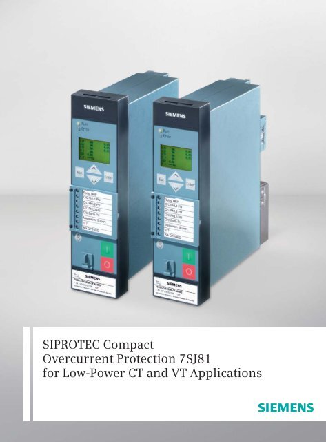
<strong>Overcurrent</strong> <strong>Protection</strong> <strong>7SJ81</strong><br />
Fig. 3/1 <strong>7SJ81</strong> front view<br />
Fig. 3/2 <strong>7SJ81</strong> rear view<br />
• IEC 61850 with integrated redundancy (electrical or<br />
optical)<br />
• Relay-to-relay communication through Ethernet with<br />
IEC 61850 GOOSE<br />
• Millisecond-accurate time synchronization through<br />
Ethernet with SNTP.<br />
<strong>SIPROTEC</strong> <strong>Compact</strong> <strong>Protection</strong> Devices <strong>7SJ81</strong> · Chapter <strong>7SJ81</strong> <strong>for</strong> the Edition 2.0 of the catalog E50001-K4403-A011-x-7600 · February 2012<br />
LSP3.01-0024-en.eps<br />
LSP3.01-0025.eps<br />
3/3<br />
1<br />
2<br />
3<br />
4<br />
5<br />
6<br />
7<br />
8<br />
9
3<br />
<strong>Overcurrent</strong> <strong>Protection</strong> <strong>7SJ81</strong><br />
<strong>for</strong> <strong>Low</strong>-<strong>Power</strong> CT and VT Applications – Function overview<br />
<strong>Protection</strong> functions IEC ANSI No.<br />
Instantaneous and defi nite time-overcurrent protection (phase/neutral) I>, I >>, I >>>, I E>, I E>>, I E>>>; I p, I Ep 50, 50N; 51, 51N<br />
Directional time-overcurrent protection I dir>, I >>, I p dir 67<br />
Directional overcurrent protection <strong>for</strong> ground-faults I E dir>, I E dir>>, I Ep dir 67N<br />
Directional/non-directional sensitive ground-fault detection I EE>, I EE>>, I EEp 67Ns , 50Ns<br />
Overvoltage protection, zero-sequence system<br />
Inrush restraint<br />
VE, V0> 59N<br />
Undercurrent monitoring I < 37<br />
Thermal overload protection ϑ> 49<br />
Undervoltage/overvoltage protection V 27/59<br />
Overfrequency/underfrequency protection f 81O/U<br />
Breaker failure protection 50BF<br />
Phase-balance current protection (negative-sequence protection) I2> 46<br />
Unbalance-voltage protection and/or phase-sequence monitoring V2>, phase sequence 47<br />
Automatic reclosing 79<br />
Fault locator FL<br />
Lockout 86<br />
Forward-power, reverse-power protection P, Q 32<br />
<strong>Power</strong> factor cos ϕ 55<br />
Rate-of-frequency-change protection df/dt 81R<br />
Table 3/1 Function overview<br />
Control functions/programmable logic<br />
• Commands <strong>for</strong> the ctrl. of CB, disconnect switches<br />
(isolators/isolating switches)<br />
• Control through keyboard, binary inputs, DIGSI 4 or<br />
SCADA system<br />
• User-defi ned PLC logic with CFC (e.g. interlocking).<br />
Monitoring functions<br />
• Operational measured values I, V, f<br />
• Energy metering values Wp, Wg<br />
• Circuit-breaker wear monitoring<br />
• Minimum and maximum values<br />
• Trip circuit supervision (74TC)<br />
• Fuse failure monitor<br />
• 8 oscillographic fault records.<br />
Communication interfaces<br />
• System/service interface<br />
– IEC 61850<br />
– IEC 60870-5-103<br />
– PROFIBUS-DP<br />
– DNP 3.0<br />
– MODBUS RTU<br />
• Ethernet interface <strong>for</strong> DIGSI 4<br />
• USB front interface <strong>for</strong> DIGSI 4.<br />
Hardware<br />
• 4 current inputs<br />
• 0/3 voltage inputs<br />
• 3/7 binary inputs (thresholds confi gurable using software)<br />
• 5/8 binary outputs (2 changeover/Form C contacts)<br />
• 1 live-status contact<br />
• Pluggable voltage terminals.<br />
3/4 <strong>SIPROTEC</strong> <strong>Compact</strong> <strong>Protection</strong> Devices <strong>7SJ81</strong> · Chapter <strong>7SJ81</strong> <strong>for</strong> the Edition 2.0 of the catalog E50001-K4403-A011-x-7600 · February 2012
<strong>Overcurrent</strong> <strong>Protection</strong> <strong>7SJ81</strong><br />
Type Order No. Ratio Type Order No.<br />
lopo CT 16 100 008 100A/225mV LPCT 25-A (D120) with CAT.5 cable and RJ45 connector 3-16100000<br />
lopo CT 16 100 005 50A/22.5mV LPCT 25-A (D120) with CAT.5 cable and RJ45 connector 3-16100000<br />
lopo CT 16 110 005 50A/22.5mV LPCT 25-B (D108) with CAT.5 cable and RJ45 connector 3-16110000<br />
lopo CT 16 120 005 50A/22.5mV LPCT 25-C (D300) with CAT.5 cable and RJ45 connector 3-16120000<br />
lopo CT 16 130 005 50A/22.5mV LPCT 25-D (D55) with CAT.5 cable and RJ45 connector 3-16130000<br />
split-core lopo CT 16 140 005 60A/7.07V LPCT K-60 (D120) with CAT.5 cable and RJ45 connector 3-16140000<br />
lopo CT 16 150 005 50A/22.5mV LPCT 25-E (oval) with CAT.5 cable and RJ45 connector 3-16150003<br />
lopo VT (resistive divider) see table below LPVT-A with CAT.5 cable and RJ45 connector 3-16300000<br />
lopo VT (resistive divider) see table below LPVT-I with CAT.5 cable and RJ45 connector (size 2) 3-16320000<br />
lopo VT (resistive divider) see table below LPVT-I with CAT.5 cable and RJ45 connector (size 3) 3-16320010<br />
lopo VT (resistive divider) see table below LPVT-G with CAT.5 cable and RJ45 connector 3-16340000<br />
lopo VT (resistive divider) see table below LPVT-P with CAT.5 cable and RJ45 connector 3-16360000<br />
lopo VT (resistive divider) see table below LPVT-F with CAT.5 cable and RJ45 connector 3-16380000<br />
lopo VT (resistive divider) see table below LPVT-S with CAT.5 cable and RJ45 connector 3-16380101<br />
combined (lopo CT with<br />
integrated resistive divider)<br />
16 401 202 CT: 50A/22.5mV<br />
VT: prim: 10kV/√3<br />
sec: 3.25V/√3<br />
Table 3/2 Available low-power trans<strong>for</strong>mers from TRENCH<br />
CAT.5 cable length: Standard 6.5 m<br />
Contact partner: Rolf.Fluri@siemens.com<br />
Trench Switzerland AG, Lehenmattstraße 353, CH-4028 Basel<br />
LOPO Voltage Trans<strong>for</strong>mers<br />
Type<br />
4 5 6 7 8<br />
Order No.: 16 3 2<br />
<strong>for</strong> <strong>Low</strong>-<strong>Power</strong> CT and VT Applications – Function overview<br />
LPVCT-12 with CAT.5 cable and RJ45 connector; 4 x M12 3-16400002<br />
01 02 03 04 05 06 07 08<br />
Highest voltage <strong>for</strong> →<br />
equipment [kV]<br />
7.2 12 15.5 24 36 38 40 52<br />
Ratio →<br />
6kV 3.<br />
25V<br />
10kV 3.<br />
25V<br />
15kV 3.<br />
25V<br />
20kV 3.<br />
25V<br />
30kV 3.<br />
25V<br />
34. 5kV<br />
3.<br />
25V<br />
36kV 3.<br />
25V<br />
3 3 3 3 3 3 3 3 3 3 3 3 3 3<br />
45kV 3.<br />
25V<br />
3 3<br />
Drawing No.<br />
LPVT-A 0 0 → � � � � X X X X 3-16300000<br />
LPVT-I size2 2 0 → � � � � � X X X 3-16320000<br />
LPVT-I size3 2 1 → X X X X � � � � 3-16320010<br />
LPVT-G 4 0 → � � � � � � X X 3-16340000<br />
LPVT-P 6 0 → � � � � � X X X 3-16360000<br />
LPVT-F 8 0 → � � � � X X X X 3-16380000<br />
LPVT-S 8 1 → � � � � � X X X 3-16380101<br />
RJ45 connector 2<br />
Table 3/3 Order no. <strong>for</strong> LOPO voltage trans<strong>for</strong>mers<br />
<strong>SIPROTEC</strong> <strong>Compact</strong> <strong>Protection</strong> Devices <strong>7SJ81</strong> · Chapter <strong>7SJ81</strong> <strong>for</strong> the Edition 2.0 of the catalog E50001-K4403-A011-x-7600 · February 2012<br />
3/5<br />
1<br />
2<br />
3<br />
4<br />
5<br />
6<br />
7<br />
8<br />
9
3<br />
<strong>Overcurrent</strong> <strong>Protection</strong> <strong>7SJ81</strong><br />
<strong>for</strong> <strong>Low</strong>-<strong>Power</strong> CT and VT Applications– Applications<br />
The <strong>SIPROTEC</strong> <strong>Compact</strong> <strong>7SJ81</strong> unit is a numerical protection<br />
with low power CT and VT inputs. The device per<strong>for</strong>ms<br />
control and monitoring functions and there<strong>for</strong>e provides<br />
the user with a cost-effective plat<strong>for</strong>m <strong>for</strong> power system<br />
management, that ensures reliable supply of electrical power<br />
to the customers. The ergonomic design makes control easy<br />
from the relay front panel. A large, easy-to-read display was<br />
a key design factor.<br />
Control<br />
The integrated control function permits control of disconnect<br />
devices, grounding switches or circuit-breakers through<br />
the integrated operator panel, binary inputs, DIGSI 4 or the<br />
control or automation system (e.g. SICAM).<br />
Programmable logic<br />
The integrated logic characteristics (CFC) allow the user to<br />
add own functions <strong>for</strong> automation of switchgear (e.g. interlocking)<br />
or switching sequence. The user can also generate<br />
user-defi ned messages. This functionality can <strong>for</strong>m the base<br />
to create extremely fl exible transfer schemes.<br />
Operational measured values<br />
Extensive measured values (e.g. I, V), metered values<br />
(e.g.W p,W q) and limit values (e.g. <strong>for</strong> voltage, frequency)<br />
provide improved system management.<br />
52<br />
Busbar<br />
Local/remote control<br />
Commands/Feedbacks<br />
74TC Trip circuit supervision<br />
86<br />
Operation<br />
Fig.3/3 Function diagram<br />
Esc Enter<br />
Lock out<br />
7 8 9<br />
4 5 6<br />
1 2 3<br />
Fn 0 .<br />
50N 51N<br />
Communication module<br />
RS232/485/FO/<br />
Ethernet<br />
IEC 60870-5-103<br />
IEC 61850<br />
PROFIBUS-DP<br />
DNP 3.0<br />
MODBUS RTU<br />
IN>, IN>>,<br />
IN>>><br />
IN-TOC<br />
AR Automatic reclosing<br />
BF Breaker Failure <strong>Protection</strong><br />
CFC logic<br />
Fault recording<br />
Operational measured values<br />
Limits<br />
Mean value<br />
min/max-memory<br />
Metered energy: as counting pulses<br />
I>, I>>,<br />
IN>, IN>>,<br />
I>>><br />
50<br />
I-TOC<br />
51<br />
IN>>> IN-TOC<br />
50N 51N<br />
I2><br />
46<br />
><br />
49<br />
InRush<br />
BLK<br />
BF<br />
50BF<br />
I<<br />
37<br />
AND<br />
Operational indications<br />
Event logs, trip logs, fault records and statistics documents are<br />
stored in the relay to provide the user or operator with all the key<br />
data required to operate modern substations.<br />
Line protection<br />
The <strong>7SJ81</strong> units can be used <strong>for</strong> line protection of high and<br />
medium-voltage networks with grounded, low-resistance<br />
grounded, isolated or a compensated neutral point.<br />
Trans<strong>for</strong>mer protection<br />
The relay provides all the functions <strong>for</strong> backup protection <strong>for</strong><br />
trans<strong>for</strong>mer differential protection. The inrush suppression<br />
effectively prevents unwanted trips that can be caused by<br />
inrush currents.<br />
Backup protection<br />
The <strong>7SJ81</strong> can be used as a backup protection <strong>for</strong> a wide<br />
range of applications.<br />
Switchgear cubicles <strong>for</strong> high/medium voltage<br />
All units are designed specifi cally to meet the requirements<br />
of medium-voltage applications. In general, no separate<br />
measuring instruments (e.g., <strong>for</strong> current, voltage, frequency,<br />
…) or additional control components are necessary in the<br />
cubicles.<br />
Fault Locator<br />
Directional supplement<br />
Additional Directional ground<br />
fault protection<br />
3/6 <strong>SIPROTEC</strong> <strong>Compact</strong> <strong>Protection</strong> Devices <strong>7SJ81</strong> · Chapter <strong>7SJ81</strong> <strong>for</strong> the Edition 2.0 of the catalog E50001-K4403-A011-x-7600 · February 2012<br />
79 AR<br />
I2><br />
I<<br />
I, V, P, Q,<br />
cos �, f<br />
V, f, P<br />
FL 47<br />
Unbalanced load protection<br />
Thermal overload protection<br />
Undercurrent monitoring<br />
Flexible protection functions<br />
P, Q cos� df/dt<br />
32 55 81R<br />
f<br />
81U/O<br />
67Ns<br />
V><br />
59 27<br />
Phase sequence<br />
monitoring<br />
I>, I>> I-<br />
TOC<br />
67 67N<br />
INs>,<br />
INs>><br />
67Ns-TOC VN><br />
59N<br />
V<<br />
IN>, IN>>,<br />
IN-TOC<br />
Visio-LSA4783a-us.pdf
<strong>Protection</strong> functions<br />
Time-overcurrent protection (ANSI 50, 50N, 51, 51N)<br />
This function is based on the phase-selective measurement<br />
of the three phase currents and the ground current (four<br />
trans<strong>for</strong>mers). Three defi nite-time overcurrent protection<br />
elements (DMT) are available both <strong>for</strong> the phase and the<br />
ground elements. The current threshold and the delay time<br />
can be set in a wide range.<br />
Inverse-time overcurrent protection characteristics (IDMTL)<br />
can also be selected and activated.<br />
Reset characteristics<br />
Time coordination with electromechanical relays is made<br />
easy with the inclusion of the reset characteristics according<br />
to ANSI C37.112 and IEC 60255-3/BS 142 standards. When<br />
using the reset characteristic (disk emulation), the reset process<br />
is initiated after the fault current has disappeared. This<br />
reset process corresponds to the reverse movement of the<br />
Ferraris disk of an electromechanical relay (disk emulation).<br />
Available inverse-time characteristics<br />
Characteristics acc. to IEC 60255-3 ANSI/IEEE<br />
Inverse � �<br />
Short inverse<br />
Long inverse � �<br />
Moderately inverse<br />
Very inverse � �<br />
Extremely inverse � �<br />
Table 3/4 Available inverse-time characteristics<br />
Inrush restraint<br />
If second harmonic content is detected during the energization<br />
of a trans<strong>for</strong>mer, the pickup of stages I >, I p, I >dir<br />
and I p dir is blocked.<br />
Dynamic settings group switching<br />
In addition to the static parameter changeover, the pickup<br />
thresholds and the tripping times <strong>for</strong> the directional and<br />
non-directional time-overcurrent protection functions can<br />
be changed over dynamically. As changeover criterion, the<br />
circuit-breaker position, the prepared auto-reclosure, or a<br />
binary input can be selected.<br />
Directional comparison protection (cross-coupling)<br />
It is used <strong>for</strong> selective instantaneous tripping of sections<br />
fed from two sources, i.e. without the disadvantage of time<br />
delays of the set characteristic. The directional comparison<br />
protection is suitable if the distances between the protection<br />
zones are not signifi cant and pilot wires are available <strong>for</strong><br />
signal transmission. In addition to the directional comparison<br />
protection, the directional coordinated time-overcurrent<br />
protection is used <strong>for</strong> complete selective backup protection.<br />
�<br />
�<br />
<strong>Overcurrent</strong> <strong>Protection</strong> <strong>7SJ81</strong><br />
<strong>for</strong> <strong>Low</strong>-<strong>Power</strong> CT and VT Applications– Application sheets<br />
Directional time-overcurrent protection (ANSI 67, 67N)<br />
Directional phase and ground protection are separate functions.<br />
They operate in parallel to the non-directional overcurrent<br />
elements. Their pickup values and delay times can be set<br />
separately. Defi nite-time and inverse-time characteristics are<br />
offered. The tripping characteristic can be rotated by ± 180<br />
degrees.<br />
By making use of the voltage memory, the directionality can<br />
be determined reliably even <strong>for</strong> close-in (local) faults. If the<br />
primary switching device closes onto a fault and the voltage<br />
is too low to determine direction, the direction is determined<br />
using voltage from the memorized voltage. If no voltages are<br />
stored in the memory, tripping will be according to the set<br />
characteristic.<br />
For ground protection, users can choose whether the direction<br />
is to be calculated using the zero-sequence or negativesequence<br />
system quantities (selectable). If the zero-sequence<br />
voltage tends to be very low due to the zero-sequence impedance<br />
it will be better to use the negative-sequence quantities.<br />
Fig. 3/4 Directional characteristics of the directional timeovercurrent<br />
protection<br />
(Sensitive) directional ground-fault detection<br />
(ANSI 59N/64, 67Ns, 67N)<br />
For isolated-neutral and compensated networks, the direction<br />
of power fl ow in the zero sequence is calculated from the<br />
zero-sequence current I 0 and zero-sequence voltage V 0. For<br />
networks with an isolated neutral, the reactive current component<br />
is evaluated; <strong>for</strong> compensated networks, the active<br />
current component or residual resistive current is evaluated.<br />
For special network conditions, e.g. high-resistance grounded<br />
networks with ohmic-capacitive ground-fault current or lowresistance<br />
grounded networks with ohmic-inductive current,<br />
the tripping characteristics can be rotated approximately<br />
± 45 degrees (see Fig.2/5).<br />
Two modes of ground-fault direction detection can be implemented:<br />
tripping or “signalling only mode”.<br />
<strong>SIPROTEC</strong> <strong>Compact</strong> <strong>Protection</strong> Devices <strong>7SJ81</strong> · Chapter <strong>7SJ81</strong> <strong>for</strong> the Edition 2.0 of the catalog E50001-K4403-A011-x-7600 · February 2012<br />
3/7<br />
1<br />
2<br />
3<br />
4<br />
5<br />
6<br />
7<br />
8<br />
9
3<br />
<strong>Overcurrent</strong> <strong>Protection</strong> <strong>7SJ81</strong><br />
<strong>for</strong> <strong>Low</strong>-<strong>Power</strong> CT and VT Applications – Application sheets<br />
(Sensitive) directional ground-fault detection<br />
(ANSI 59N/64, 67Ns, 67N) (contin.)<br />
It has the following functions:<br />
• TRIP via the displacement voltage VE • Two instantaneous elements or one instantaneous plus<br />
one user-defi ned characteristic.<br />
• Each element can be set to <strong>for</strong>ward, reverse or nondirectional.<br />
• The function can also be operated in the insensitive mode<br />
as an additional short-circuit protection.<br />
Fig. 3/5 Directional determination using cosine measurements <strong>for</strong><br />
compensated networks<br />
(Sensitive) ground-fault detection<br />
(ANSI 50Ns, 51Ns / 50N, 51N)<br />
For high-resistance grounded networks, a sensitive input<br />
trans<strong>for</strong>mer is connected to a split-core low-power current<br />
trans<strong>for</strong>mer (also called core-balance CT). The function can<br />
also be operated in the normal mode as an additional shortcircuit<br />
protection <strong>for</strong> neutral or residual ground protection.<br />
Phase-balance current protection (ANSI 46)<br />
(Negative-sequence protection)<br />
By measuring current on the high side of the trans<strong>for</strong>mer,<br />
the two-element phase-balance current/negative-sequence<br />
protection detects high-resistance phase-to-phase faults<br />
and phase-to-ground faults on the low side of a trans<strong>for</strong>mer<br />
(e.g. Dy 5). This function provides backup protection <strong>for</strong><br />
high-resistance faults through the trans<strong>for</strong>mer.<br />
Breaker failure protection (ANSI 50BF)<br />
If a faulted portion of the electrical circuit is not disconnected<br />
when a trip command is issued to a circuit-breaker, another<br />
trip command can be initiated using the breaker failure protection<br />
which trips the circuit-breaker of an upstream feeder.<br />
Breaker failure is detected if, after a trip command is issued<br />
and the current keeps on fl owing into the faulted circuit. It<br />
is also possible to make use of the circuit-breaker position<br />
contacts (52a or 52b) <strong>for</strong> indication as opposed to the current<br />
fl owing through the circuit-breaker.<br />
Automatic reclosing (ANSI 79)<br />
Multiple re-close cycles can be set by the user and lockout<br />
will occur if a fault is present after the last re-close cycle.<br />
The following functions are available:<br />
• 3-pole ARC <strong>for</strong> all types of faults<br />
• Separate settings <strong>for</strong> phase and ground faults<br />
• Multiple ARC, one rapid auto-reclosure (RAR) and up to<br />
nine delayed auto-reclosures (DAR)<br />
• Initiation of the ARC is dependant on the trip command<br />
selected (e.g. I 2>, I>>, I p, I dir>)<br />
• The ARC function can be blocked by activating a binary input<br />
• The ARC can be initiated from external or by the PLC logic (CFC)<br />
• The directional and non-directional elements can either<br />
be blocked or operated non-delayed depending on the<br />
auto-reclosure cycle<br />
• If the ARC is not ready it is possible to per<strong>for</strong>m a dynamic<br />
setting change of the directional and non-directional<br />
overcurrent elements.<br />
Flexible protection functions<br />
The <strong>7SJ81</strong> enables the user to easily add up to 20 additional<br />
protection functions. Parameter defi nitions are used to link<br />
standard protection logic with any chosen characteristic<br />
quantity (measured or calculated quantity). The standard<br />
logic consists of the usual protection elements such as the<br />
pickup set point, the set delay time, the TRIP command,<br />
a block function, etc. The mode of operation <strong>for</strong> current,<br />
voltage, power and power factor quantities can be threephase<br />
or single-phase. Almost all quantities can be operated<br />
with ascending or descending pickup stages (e.g. under and<br />
overvoltage). All stages operate with protection priority.<br />
<strong>Protection</strong> functions/stages available are based on the<br />
Fig, 3/6 Flexible protection function<br />
3/8 <strong>SIPROTEC</strong> <strong>Compact</strong> <strong>Protection</strong> Devices <strong>7SJ81</strong> · Chapter <strong>7SJ81</strong> <strong>for</strong> the Edition 2.0 of the catalog E50001-K4403-A011-x-7600 · February 2012
available measured analog quantities:<br />
Function ANSI<br />
I>, IE> 50, 50N<br />
V, VE> 27, 59, 59N<br />
3I0>, I1>, I2>, I2/ I1>, 3V0>, V1> < 50N, 46, 59N, 47<br />
P> < 32<br />
cos ϕ 55<br />
f > < 81O, 81U<br />
df/dt > < 81R<br />
Table 3/5 Available fl exible protection functions<br />
For example, the following can be implemented:<br />
• Reverse power protection (ANSI 32R)<br />
• Rate-of-frequency-change protection (ANSI 81R)<br />
Trip circuit supervision (ANSI 74TC)<br />
One or two binary inputs can be used <strong>for</strong> monitoring the<br />
circuit-breaker trip coil including its incoming cables. An alarm<br />
signal is generated whenever the circuit is interrupted.<br />
Lockout (ANSI 86)<br />
All binary output statuses can be memorized. The LED reset<br />
key is used to reset the lockout state. The lockout state is also<br />
stored in the event of supply voltage failure. Reclosure can<br />
only occur after the lockout state is reset.<br />
Thermal overload protection (ANSI 49)<br />
To protect cables and trans<strong>for</strong>mers, an overload protection<br />
function with an integrated warning/alarm element <strong>for</strong><br />
temperature and current can be used. The temperature is<br />
calculated using a thermal homogeneous body model (per<br />
IEC 60255-8), it considers the energy entering the equipment<br />
and the energy losses. The calculated temperature is<br />
constantly adjusted according to the calculated losses. The<br />
function considers loading history and fl uctuations in load.<br />
Settable dropout delay times<br />
If the relays are used in conjunction with electromechanical<br />
relays, in networks with intermittent faults, the long dropout<br />
times of the electromechanical relay (several hundred milliseconds)<br />
can lead to problems in terms of time coordination/<br />
grading. Proper time coordination/grading is only possible if<br />
the dropout or reset time is approximately the same. This is<br />
why the parameter <strong>for</strong> dropout or reset times can be defi ned<br />
<strong>for</strong> certain functions, such as time-overcurrent protection,<br />
ground short-circuit and phase-balance current protection.<br />
Undercurrent monitoring (ANSI 37)<br />
A sudden drop in current, which can occur due to a reduced<br />
load, is detected with this function. This may be due to shaft<br />
that breaks, no-load operation of pumps or fan failure.<br />
<strong>Overcurrent</strong> <strong>Protection</strong> <strong>7SJ81</strong><br />
<strong>for</strong> <strong>Low</strong>-<strong>Power</strong> CT and VT Applications – Application sheets<br />
Overvoltage protection (ANSI 59)<br />
The two-element overvoltage protection detects unwanted<br />
network and machine overvoltage conditions. The function<br />
can operate either with phase-to-phase, phase-to-ground,<br />
positive phase-sequence or negative phase-sequence voltage.<br />
Three-phase and single-phase connections are possible.<br />
Undervoltage protection (ANSI 27)<br />
The two-element undervoltage protection provides protection<br />
against dangerous voltage drops (especially <strong>for</strong> electric<br />
machines). Applications include the isolation of generators<br />
or motors from the network to avoid undesired operating<br />
conditions and a possible loss of stability. Proper operating<br />
conditions of electrical machines are best evaluated with<br />
the positive-sequence quantities. The protection function is<br />
active over a wide frequency range (45 to 55, 55 to 65 Hz).<br />
Even when falling below this frequency range the function<br />
continues to work, however, with decreased accuracy. The<br />
function can operate either with phase-to-phase, phaseto-ground<br />
or positive phase-sequence voltage, and can be<br />
monitored with a current criterion. Three-phase and singlephase<br />
connections are possible.<br />
Frequency protection (ANSI 81O/U)<br />
Frequency protection can be used <strong>for</strong> overfrequency and<br />
underfrequency protection. Electric machines and parts<br />
of the system are protected from unwanted frequency<br />
deviations. Unwanted frequency changes in the network<br />
can be detected and the load can be removed at a specifi ed<br />
frequency setting. Frequency protection can be used over<br />
a wide frequency range (40 to 60 (<strong>for</strong> 50 Hz), 50 to 70 (<strong>for</strong><br />
60 Hz)). There are four elements (individually set as overfrequency,<br />
underfrequency or OFF) and each element can<br />
be delayed separately. Blocking of the frequency protection<br />
can be per<strong>for</strong>med by activating a binary input or by using an<br />
undervoltage element.<br />
Fault locator (ANSI FL)<br />
The integrated fault locator calculates the fault impedance<br />
and the distance to fault. The results are displayed in Ω,<br />
kilometers (miles) and in percent of the line length.<br />
Customized functions (ANSI 51V, 55 etc.)<br />
Additional functions, which are not time critical, can be implemented<br />
using the CFC measured values. Typical functions<br />
include reverse power, voltage controlled overcurrent, phase<br />
angle detection, and zero-sequence voltage detection.<br />
Futher Functions<br />
Measured values<br />
The r.m.s. values are calculated from the acquired current<br />
and voltage along with the power factor, frequency, active<br />
and reactive power. The following functions are available <strong>for</strong><br />
measured value processing:<br />
<strong>SIPROTEC</strong> <strong>Compact</strong> <strong>Protection</strong> Devices <strong>7SJ81</strong> · Chapter <strong>7SJ81</strong> <strong>for</strong> the Edition 2.0 of the catalog E50001-K4403-A011-x-7600 · February 2012<br />
3/9<br />
1<br />
2<br />
3<br />
4<br />
5<br />
6<br />
7<br />
8<br />
9
3<br />
<strong>Overcurrent</strong> <strong>Protection</strong> <strong>7SJ81</strong><br />
<strong>for</strong> <strong>Low</strong>-<strong>Power</strong> CT and VT Applications – Application sheets<br />
Measured values (contin.)<br />
• Currents I L1, I L2, I L3, I N, I EE<br />
• Voltages V L1, V L2, V L3, V 12, V 23, V 31<br />
• Symmetrical components I1, I2, 3I0; V1, V2, 3V0 • <strong>Power</strong> Watts, Vars, VA/P, Q, S (P, Q: total and phase<br />
selective)<br />
• <strong>Power</strong> factor cos ϕ (total and phase selective)<br />
• Frequency<br />
• Energy ± kWh, ± kVarh, <strong>for</strong>ward and reverse power fl ow<br />
• Mean as well as minimum and maximum current and<br />
voltage values<br />
• Operating hours counter<br />
• Mean operating temperature of the overload function<br />
• Limit value monitoring<br />
Limit values can be monitored using programmable logic<br />
in the CFC. Commands can be derived from this limit value<br />
indication.<br />
• Zero suppression<br />
In a certain range of very low measured values, the value<br />
is set to zero to suppress interference.<br />
Metered values<br />
For internal metering, the unit can calculate an energy metered<br />
value from the measured current and voltage values. If<br />
an external meter with a metering pulse output is available,<br />
the <strong>7SJ81</strong> can obtain and process metering pulses through<br />
an indication input. The metered values can be displayed<br />
and passed on to a control center as an accumulated value<br />
with reset. A distinction is made between <strong>for</strong>ward, reverse,<br />
active and reactive energy.<br />
Circuit-breaker wear monitoring/<br />
circuit-breaker remaining service life<br />
Methods <strong>for</strong> determining circuit-breaker contact wear or<br />
the remaining service life of a circuit-breaker (CB) allow CB<br />
maintenance intervals to be aligned to their actual degree of<br />
wear. The benefi t lies in reduced maintenance costs.<br />
There is no exact mathematical method to calculate the<br />
wear or the remaining service life of a circuit-breaker that<br />
takes arc-chamber’s physical conditions into account when<br />
the CB opens.<br />
This is why various methods of determining CB wear have<br />
evolved which refl ect the different operator philosophies. To<br />
do justice to these, the relay offers several methods:<br />
• ΣI<br />
• ΣI x , with x = 1..3<br />
• Σi 2t. The devices also offer a new method <strong>for</strong> determining the<br />
remaining service life:<br />
• Two-point method.<br />
P1: Permissible<br />
number of<br />
operating cycles<br />
at rated normal<br />
current<br />
P2: Permissible<br />
number of<br />
operating cycles<br />
at rated shortcircuit<br />
current<br />
Fig. 3/7 Permissible number of operating cycles as a function of<br />
breaking current<br />
The CB manufacturers double-logarithmic switching cycle<br />
diagram (see Fig. 3/5) and the breaking current at the time<br />
of contact opening serve as the basis <strong>for</strong> this method. After<br />
CB opening, the two-point method calculates the remaining<br />
number of possible switching cycles. Two points P1 and P2<br />
only have to be set on the device. These are specifi ed in the<br />
CB’s technical data.<br />
All of these methods are phase-selective and a limit value<br />
can be set in order to obtain an alarm if the actual value falls<br />
below or exceeds the limit value during determination of the<br />
remaining service life.<br />
Commissioning<br />
Commissioning could not be easier and is supported by<br />
DIGSI 4. The status of the binary inputs can be read individually<br />
and the state of the binary outputs can be set individually.<br />
The operation of switching elements (circuit-breakers,<br />
disconnect devices) can be checked using the switching<br />
functions of the relay. The analog measured values are<br />
represented as wide-ranging operational measured values.<br />
To prevent transmission of in<strong>for</strong>mation to the control center<br />
during maintenance, the communications can be disabled<br />
to prevent unnecessary data from being transmitted. During<br />
commissioning, all indications with test tag <strong>for</strong> test purposes<br />
can be connected to a control and protection system.<br />
Test operation<br />
During commissioning, all indications with test tag can be<br />
passed to a control system <strong>for</strong> test purposes.<br />
3/10 <strong>SIPROTEC</strong> <strong>Compact</strong> <strong>Protection</strong> Devices <strong>7SJ81</strong> · Chapter <strong>7SJ81</strong> <strong>for</strong> the Edition 2.0 of the catalog E50001-K4403-A011-x-7600 · February 2012
Radial systems<br />
General hints:<br />
The relay at the far end (D) from the<br />
infeed has the shortest tripping time.<br />
Relays further upstream have to be<br />
time-graded against downstream<br />
relays in steps of about 0.3 s.<br />
Earth-fault detection in isolated or<br />
compensated systems<br />
In isolated or compensated systems,<br />
an occurred earth fault can be easily<br />
found by means of sensitive directional<br />
earth-fault detection.<br />
<strong>Overcurrent</strong> <strong>Protection</strong> <strong>7SJ81</strong><br />
<strong>for</strong> <strong>Low</strong>-<strong>Power</strong> CT and VT Applications – Application examples<br />
1) Auto-reclosure<br />
(ANSI 79) only with<br />
overhead lines<br />
2) Unbalanced load<br />
protection (ANSI 46)<br />
as backup protection<br />
against asymmetrical<br />
faults<br />
Further power supply<br />
*<br />
Load<br />
*<br />
Fig. 3/8 <strong>Protection</strong> concept with overcurrent-time protection<br />
1) The sensitive current<br />
measurement of the<br />
earth current should<br />
be made by a zerosequence<br />
low-power<br />
current trans<strong>for</strong>mer,<br />
e.g. LPCT K-60 from<br />
TRENCH<br />
1)<br />
52<br />
Load<br />
<strong>SIPROTEC</strong> <strong>Compact</strong> <strong>Protection</strong> Devices <strong>7SJ81</strong> · Chapter <strong>7SJ81</strong> <strong>for</strong> the Edition 2.0 of the catalog E50001-K4403-A011-x-7600 · February 2012<br />
A<br />
B<br />
C<br />
D<br />
IN>t dir.<br />
52<br />
52<br />
52<br />
52<br />
Infeed<br />
Infeed<br />
I>> I>t<br />
50 51<br />
67Ns<br />
Fig. 3/9 <strong>Protection</strong> concept <strong>for</strong> directional earth-fault detection<br />
I>t<br />
Trans<strong>for</strong>mer protection<br />
Busbar<br />
51 51N 46<br />
2)<br />
I>t<br />
IN><br />
t<br />
Busbar<br />
IN><br />
t<br />
51 51N 46<br />
Busbar<br />
I2>t<br />
I2>t<br />
I>t IN>t I2>t<br />
51 51N 46<br />
Busbar<br />
Visio-LAS4839-us.pdf<br />
Visio-LAS4840-us.pdf<br />
3/11<br />
1<br />
2<br />
3<br />
4<br />
5<br />
6<br />
7<br />
8<br />
9
3<br />
<strong>Overcurrent</strong> <strong>Protection</strong> <strong>7SJ81</strong><br />
<strong>for</strong> <strong>Low</strong>-<strong>Power</strong> CT and VT Applications – application examples<br />
Ring-main cable<br />
With the directional comparison<br />
protection, 100% of the line can be<br />
protected via instantaneous tripping<br />
in case of infeed from two sources<br />
(ring-main cable).<br />
For lines with infeed from two sources,<br />
no selectivity can be achieved<br />
with a simple defi nite-time overcurrent<br />
protection. There<strong>for</strong>e, the<br />
directional defi nite-time overcurrent<br />
protection must be used. A nondirectional<br />
defi nite-time overcurrent<br />
protection is enough only in the<br />
corresponding busbar feeders. The<br />
grading is done from the other end<br />
respectively.<br />
Advantage: 100% protection of the<br />
line via instantaneous<br />
tripping, and easy<br />
setting.<br />
Disadvantage: Tripping times increase<br />
towards the infeed.<br />
52<br />
52<br />
52<br />
52<br />
Infeed Infeed<br />
Overhead line<br />
or cable 1<br />
I>t IN>t �>t I2>t<br />
51 51N 49 46<br />
I>t IN>t dir. I>t IN>t<br />
67 67N 51 51N<br />
67 67N 51 51N<br />
I>t<br />
Overhead line<br />
or cable 3<br />
IN>t dir. I>t IN>t<br />
I>t IN>t dir. I>t IN>t<br />
67 67N 51 51N<br />
I>t IN>t �>t I2>t<br />
51 51N 49 46<br />
Fig. 3/10 <strong>Protection</strong> concept of ring power systems<br />
Direct.Compar.Pickup<br />
Overhead line<br />
or cable 2<br />
Direct.Compar.Pickup<br />
Overhead line<br />
or cable 4<br />
Load Load<br />
<strong>Protection</strong> as in<br />
the case of line<br />
or cable 1<br />
<strong>Protection</strong> as in<br />
the case of line<br />
or cable 3<br />
3/12 <strong>SIPROTEC</strong> <strong>Compact</strong> <strong>Protection</strong> Devices <strong>7SJ81</strong> · Chapter <strong>7SJ81</strong> <strong>for</strong> the Edition 2.0 of the catalog E50001-K4403-A011-x-7600 · February 2012<br />
52<br />
52<br />
52<br />
52 52<br />
52<br />
52<br />
52<br />
52<br />
Visio-LSA4841-us.pdf
Busbar protection by overcurrent<br />
relays with reverse interlocking<br />
Applicable to distribution busbars<br />
without substantial (< 0.25 x I N)<br />
backfeed from the outgoing feeders.<br />
Line feeder with load shedding<br />
In unstable power systems (e.g. solitary<br />
systems, emergency power supply<br />
in hospitals), it may be necessary<br />
to isolate selected consumers from<br />
the power system in order to protect<br />
the overall system. The overcurrenttime<br />
protection functions are effective<br />
only in the case of a short-circuit.<br />
Overloading of the generator can be<br />
measured as a frequency or voltage<br />
drop.<br />
<strong>Overcurrent</strong> <strong>Protection</strong> <strong>7SJ81</strong><br />
<strong>for</strong> <strong>Low</strong>-<strong>Power</strong> CT and VT Applications – application examples<br />
Fig. 3/11 Busbar protection via overcurrent relays with reverse interlocking<br />
Fig. 3/12 Line feeder with load shedding<br />
<strong>SIPROTEC</strong> <strong>Compact</strong> <strong>Protection</strong> Devices <strong>7SJ81</strong> · Chapter <strong>7SJ81</strong> <strong>for</strong> the Edition 2.0 of the catalog E50001-K4403-A011-x-7600 · February 2012<br />
Infeed<br />
t0 = 50 ms<br />
Reverse interlocking<br />
50/50N 51/51N<br />
I>> I>t I>> I>t<br />
I>> I>t<br />
50/50N 51/51N 50/50N 51/51N 50/50N 51/51N<br />
I>>t0<br />
52 52 52<br />
52<br />
V< f<<br />
27 81U<br />
I>, I>>,<br />
I>>> IN>><br />
50 50N<br />
79M<br />
52<br />
I>, Ip<br />
IN>,<br />
INTOC<br />
51 51N<br />
> I2> Final trip<br />
49 46 86<br />
Busbar<br />
Visio-LSA2216-us.pdf<br />
Busbar<br />
Visio-LSA4842-us.pdf<br />
3/13<br />
1<br />
2<br />
3<br />
4<br />
5<br />
6<br />
7<br />
8<br />
9
3<br />
<strong>Overcurrent</strong> <strong>Protection</strong> <strong>7SJ81</strong><br />
<strong>for</strong> <strong>Low</strong>-<strong>Power</strong> CT and VT Applications – application examples<br />
Automatic reclosing<br />
The auto-reclosure function (AR) has starting<br />
and blocking options. In the opposite<br />
example, the application of the blocking<br />
of the high-current stages is represented<br />
according to the reclosing cycles. The<br />
overcurrent-time protection is graded<br />
(stages I, I p) according to the grading plan.<br />
If an auto-reclosure function is installed<br />
in the incoming supply of a feeder, fi rst of<br />
all the complete feeder is tripped instantaneously<br />
in case of fault. Arc faults will be<br />
extinguished independently of the fault<br />
location. Other protection relays or fuses<br />
do not trip (fuse saving scheme). After<br />
successful auto-reclosure, all consumers<br />
are supplied with energy again. If there is<br />
a permanent fault, further reclosing cycles<br />
will be per<strong>for</strong>med. Depending on the setting<br />
of the AR, the instantaneous tripping<br />
stage in the infeed is blocked in the fi rst,<br />
second or third cycle, i.e., now the grading<br />
is effective according to the grading plan.<br />
Depending on the fault location, overcurrent<br />
relays with faster grading, fuses, or<br />
the relay in the infeed will trip. Only the<br />
part of the feeder with the permanent<br />
fault will be shut down defi nitively.<br />
Reverse power protection with parallel<br />
infeeds<br />
If a busbar is supplied by two parallel<br />
infeeds and there is a fault in one of the<br />
infeeds, the affected busbar shall be<br />
selectively shut down, so that supply to<br />
the busbar is still possible through the<br />
remaining infeed. To do this, directional<br />
devices are required, which detect a<br />
short circuit from the busbar towards the<br />
infeed. In this context, the directional<br />
time-overcurrent protection is normally<br />
adjusted over the load current. <strong>Low</strong>current<br />
faults cannot be shut down by this<br />
protection. The reverse power protection<br />
can be adjusted far below rated power,<br />
and is thus also able to detect reverse<br />
power in case of low-current faults far<br />
below the load current. The reverse power<br />
protection is implemented through the<br />
“fl exible protection functions”.<br />
Fig. 3/13 Automatic reclosing<br />
I>, I>>, I>>><br />
50<br />
IN>><br />
IN>t, IN>>t,<br />
INTOC<br />
AR<br />
Fig. 3/14 Reverse power protection with parallel infeeds<br />
3/14 <strong>SIPROTEC</strong> <strong>Compact</strong> <strong>Protection</strong> Devices <strong>7SJ81</strong> · Chapter <strong>7SJ81</strong> <strong>for</strong> the Edition 2.0 of the catalog E50001-K4403-A011-x-7600 · February 2012<br />
52<br />
52 52<br />
52<br />
ON<br />
TRIP<br />
50N<br />
1<br />
I>t, Ip<br />
67<br />
4<br />
5<br />
I>t, I>>t, Ip<br />
51<br />
51N 79<br />
2 3<br />
Infeed Infeed<br />
A<br />
B<br />
52<br />
52<br />
67 67N 32R<br />
52<br />
67 67N 32R<br />
Feeder Feeder<br />
52<br />
52<br />
Visio-LSA2219c-us.pdf<br />
Visio-LSA4116a-us.pdf
<strong>Overcurrent</strong> <strong>Protection</strong> <strong>7SJ81</strong><br />
<strong>for</strong> <strong>Low</strong>-<strong>Power</strong> CT and VT Applications – Selection and ordering data<br />
Description Order No. Short code<br />
Measuring inputs, binary inputs and outputs<br />
Housing 1/6 19"; 4 x I, 3 BI, 5 BO, 1 live status contact<br />
Housing 1/6 19"; 4 x I, 7 BI, 8 BO, 1 live status contact<br />
Housing 1/6 19"; 4 x I, 3 x U, 3 BI, 5 BO, 1 live status contact<br />
Housing 1/6 19"; 4 x I, 3 x U, 7 BI, 8 BO, 1 live status contact<br />
<strong>Low</strong> <strong>Power</strong> Measuring Inputs<br />
Auxiliary voltage<br />
DC 24V / 48V<br />
DC 60 V / 110 V / 125 V / 220 V / 250V, AC 115V / 230V<br />
Construction<br />
Flush mounting housing, screw-type terminal<br />
Region-specifi c default- and language settings<br />
Region DE, IEC, language German (language changeable)<br />
Region World, IEC/ANSI, language English (language changeable)<br />
Port B (at bottom of device, rear)<br />
No port<br />
IEC 60870-5-103 or DIGSI 4/modem, electrical RS232<br />
IEC 60870-5-103 or DIGSI 4/modem, electrical RS485<br />
IEC 60870-5-103 or DIGSI 4/modem, optical 820 nm, ST connector<br />
Further protocols see supplement L<br />
PROFIBUS DP slave, electrical RS485<br />
PROFIBUS DP slave, optical, double ring, ST connector<br />
MODBUS, electrical RS485<br />
MODBUS, optical 820 nm, ST connector<br />
DNP 3.0, electrical RS485<br />
DNP 3.0, optical 820 nm, ST connector<br />
IEC 60870-5-103, redundant, electrical RS485, RJ45 connector<br />
IEC 61850, 100 Mbit Ethernet, electrical, double, RJ45 connector<br />
IEC 61850, 100 Mbit Ethernet, optical, double, LC connector<br />
Port A (at bottom of device, in front)<br />
No Port<br />
With Ethernet interface (DIGSI, not IEC 61850), RJ45 connector<br />
Measuring/fault recording<br />
With fault recording, average values, min/max values<br />
12345 6 7 8 9 10 11 12 13 14 15 16<br />
<strong>7SJ81</strong> 3 - - 3 –<br />
<strong>SIPROTEC</strong> <strong>Compact</strong> <strong>Protection</strong> Devices <strong>7SJ81</strong> · Chapter <strong>7SJ81</strong> <strong>for</strong> the Edition 2.0 of the catalog E50001-K4403-A011-x-7600 · February 2012<br />
1<br />
2<br />
3<br />
4<br />
3<br />
1<br />
5<br />
E<br />
A<br />
B<br />
0<br />
1<br />
2<br />
3<br />
9<br />
9<br />
9<br />
9<br />
9<br />
9<br />
9<br />
9<br />
9<br />
9<br />
0<br />
6<br />
3<br />
L<br />
0<br />
A<br />
B<br />
D<br />
E<br />
G<br />
H<br />
P<br />
R<br />
S<br />
3/15<br />
1<br />
2<br />
3<br />
4<br />
5<br />
6<br />
7<br />
8<br />
9
3<br />
<strong>Overcurrent</strong> <strong>Protection</strong> <strong>7SJ81</strong><br />
<strong>for</strong> <strong>Low</strong>-<strong>Power</strong> CT and VT Applications – Selection and ordering data<br />
Description Order No. Short code<br />
12345 6 7 8 9 10 11 12 13 14 15 16<br />
<strong>7SJ81</strong> 3 - - 3 –<br />
Basic Functionality<br />
50/51 Time-overcurrent protection phase I>, I >>, I>>>, I p<br />
50N/51N Time-overcurrent protection ground I E>, I E>>, I E>>>, I Ep<br />
50N(s)/51N(s) 1) Sensitive ground fault protection I EE>, I EE>>, I EEp<br />
49 Overload protection<br />
74TC Trip circuit supervision<br />
50BF Circuit-breaker failure protection<br />
46 Negative-sequence protection<br />
37 Undercurrent monitoring<br />
86 Lockout<br />
Parameter changeover<br />
Monitoring functions<br />
Control of circuit-breaker<br />
Flexible protection functions (current parameters)<br />
Inrush restraint<br />
Basic functionality + Directional phase & ground overcurrent, directional sensitive ground fault,<br />
voltage and frequency protection<br />
67 Directional overcurrent protection phase I >,I >>, I p<br />
67N Directional overcurrent protection ground I E>, I E>>, I Ep<br />
67N(s) 1) Directional sensitive ground fault protection I EE>, I EE>>, I EEp<br />
59N Displacement voltage<br />
27/59 Under/Overvoltage<br />
81U/O Under/Overfrequency f<br />
47 Phase rotation<br />
Flexible protection functions (current and voltage parameters):<br />
Protective function <strong>for</strong> voltage, power<br />
32/55/81R power factor, frequency change<br />
Automatic Reclosing (AR), Fault Locator (FL)<br />
Without<br />
79 With AR<br />
FL With FL 3)<br />
79/FL With AR and FL 3)<br />
1) Depending on the connected low-power ground current trans<strong>for</strong>mer the function will be either<br />
sensitive (INs) or non-sensitive (IN) 2) Only if position 6 = 1 or 2<br />
3) Only if position 6 = 3 or 4<br />
A 2)<br />
F<br />
3/16 <strong>SIPROTEC</strong> <strong>Compact</strong> <strong>Protection</strong> Devices <strong>7SJ81</strong> · Chapter <strong>7SJ81</strong> <strong>for</strong> the Edition 2.0 of the catalog E50001-K4403-A011-x-7600 · February 2012<br />
C 3)<br />
F<br />
0<br />
1<br />
2<br />
3
F1<br />
F2<br />
F3<br />
F4<br />
C3<br />
C4<br />
C5<br />
C6<br />
C7<br />
C8<br />
Visio-Figure-14-us.pdf<br />
IA<br />
IB<br />
IC<br />
IN, INS<br />
BI1<br />
BI2<br />
BI3<br />
Fig. 3/15 Connection diagram <strong>for</strong> <strong>7SJ81</strong>1<br />
<strong>Overcurrent</strong> <strong>Protection</strong> <strong>7SJ81</strong><br />
<strong>for</strong> <strong>Low</strong>-<strong>Power</strong> CT and VT Applications – Connection diagrams<br />
BO1<br />
Life Contact E10<br />
E8<br />
E7<br />
<strong>Power</strong> Supply<br />
Port B<br />
e.g. System interface<br />
Port A<br />
Ethernet interface<br />
USB-DIGSI-Interface<br />
BO2 C14<br />
C13<br />
C12<br />
BO3<br />
BO4<br />
BO5<br />
=<br />
Grounding on the case<br />
=<br />
(~) +<br />
-<br />
<strong>SIPROTEC</strong> <strong>Compact</strong> <strong>Protection</strong> Devices <strong>7SJ81</strong> · Chapter <strong>7SJ81</strong> <strong>for</strong> the Edition 2.0 of the catalog E50001-K4403-A011-x-7600 · February 2012<br />
C11<br />
C9<br />
C10<br />
E1<br />
E2<br />
E3<br />
E4<br />
E5<br />
E6<br />
C1<br />
C2<br />
A<br />
B<br />
Interference Suppression<br />
Capacitors at the Relay<br />
Contacts, Ceramic, 2.2 nF,<br />
250 V<br />
3/17<br />
1<br />
2<br />
3<br />
4<br />
5<br />
6<br />
7<br />
8<br />
9
3<br />
<strong>Overcurrent</strong> <strong>Protection</strong> <strong>7SJ81</strong><br />
<strong>for</strong> <strong>Low</strong>-<strong>Power</strong> CT and VT Applications – Connection diagrams<br />
C3<br />
C4<br />
C5<br />
C6<br />
C7<br />
C8<br />
D1<br />
D2<br />
D3<br />
D4<br />
D5<br />
D6<br />
D7<br />
D8<br />
F1 IA<br />
F2<br />
F3<br />
F4<br />
Visio-Figure-15-us.pdf<br />
IB<br />
IC<br />
IN, INS<br />
BI1<br />
BI2<br />
BI3<br />
BI4<br />
BI5<br />
BI6<br />
BI7<br />
Fig. 3/16 Connection diagram <strong>for</strong> <strong>7SJ81</strong>2<br />
Life Contact<br />
<strong>Power</strong> Supply<br />
Port B<br />
e.g. System interface<br />
Port A<br />
Ethernet interface<br />
USB-DIGSI-Interface<br />
BO1 C11<br />
C9<br />
C10<br />
BO2 C14<br />
C13<br />
C12<br />
BO3<br />
BO4<br />
BO5<br />
BO6<br />
BO7<br />
BO8<br />
3/18 <strong>SIPROTEC</strong> <strong>Compact</strong> <strong>Protection</strong> Devices <strong>7SJ81</strong> · Chapter <strong>7SJ81</strong> <strong>for</strong> the Edition 2.0 of the catalog E50001-K4403-A011-x-7600 · February 2012<br />
=<br />
=<br />
(~) +<br />
-<br />
Grounding on the case<br />
E1<br />
E2<br />
E3<br />
E4<br />
E5<br />
E6<br />
D9<br />
D10<br />
D11<br />
D12<br />
D13<br />
D14<br />
E10<br />
E8<br />
E7<br />
C1<br />
C2<br />
A<br />
B<br />
Interference Suppression<br />
Capacitors at the Relay<br />
Contacts, Ceramic, 2.2 nF,<br />
250 V
C3<br />
C4<br />
C5<br />
C6<br />
C7<br />
C8<br />
F1 IA<br />
VA-N<br />
F2<br />
IB<br />
VB-N<br />
F3<br />
IC<br />
VC-N<br />
F4<br />
IN, INS<br />
Visio-Figure-16-us.pdf<br />
BI1<br />
BI2<br />
BI3<br />
Fig. 3/17 Connection diagram <strong>for</strong> <strong>7SJ81</strong>3<br />
<strong>Overcurrent</strong> <strong>Protection</strong> <strong>7SJ81</strong><br />
<strong>for</strong> <strong>Low</strong>-<strong>Power</strong> CT and VT Applications – Connection diagrams<br />
<strong>Power</strong> Supply<br />
Port B<br />
e.g. System interface<br />
Port A<br />
Ethernet interface<br />
USB-DIGSI-Interface<br />
BO1 C11<br />
C9<br />
C10<br />
BO2 C14<br />
C13<br />
C12<br />
BO3<br />
E1<br />
E2<br />
BO4<br />
E3<br />
E4<br />
BO5<br />
E5<br />
E6<br />
Life Contact E10<br />
E8<br />
E7<br />
=<br />
Grounding on the case<br />
=<br />
(~) +<br />
-<br />
<strong>SIPROTEC</strong> <strong>Compact</strong> <strong>Protection</strong> Devices <strong>7SJ81</strong> · Chapter <strong>7SJ81</strong> <strong>for</strong> the Edition 2.0 of the catalog E50001-K4403-A011-x-7600 · February 2012<br />
C1<br />
C2<br />
A<br />
B<br />
Interference Suppression<br />
Capacitors at the Relay<br />
Contacts, Ceramic, 2.2 nF,<br />
250 V<br />
3/19<br />
1<br />
2<br />
3<br />
4<br />
5<br />
6<br />
7<br />
8<br />
9
3<br />
<strong>Overcurrent</strong> <strong>Protection</strong> <strong>7SJ81</strong><br />
<strong>for</strong> <strong>Low</strong>-<strong>Power</strong> CT and VT Applications – Connection diagrams<br />
C3<br />
C4<br />
C5<br />
C6<br />
C7<br />
C8<br />
D1<br />
D2<br />
D3<br />
D4<br />
D5<br />
D6<br />
D7<br />
D8<br />
F1 IA<br />
VA-N<br />
F2<br />
IB<br />
VB-N<br />
F3<br />
IC<br />
VC-N<br />
F4<br />
IN, INS<br />
Visio-Figure-17-us.pdf<br />
BI1<br />
BI2<br />
BI3<br />
BI4<br />
BI5<br />
BI6<br />
BI7<br />
Fig. 3/18 Connection diagram <strong>for</strong> <strong>7SJ81</strong>4<br />
<strong>Power</strong> Supply<br />
Port B<br />
e.g. System interface<br />
Port A<br />
Ethernet interface<br />
USB-DIGSI-Interface<br />
BO1 C11<br />
C9<br />
C10<br />
BO2 C14<br />
C13<br />
C12<br />
BO3<br />
E1<br />
E2<br />
BO4<br />
E3<br />
E4<br />
BO5<br />
E5<br />
E6<br />
BO6<br />
D9<br />
D10<br />
BO7<br />
D11<br />
D12<br />
BO8<br />
D13<br />
D14<br />
Life Contact E10<br />
E8<br />
E7<br />
3/20 <strong>SIPROTEC</strong> <strong>Compact</strong> <strong>Protection</strong> Devices <strong>7SJ81</strong> · Chapter <strong>7SJ81</strong> <strong>for</strong> the Edition 2.0 of the catalog E50001-K4403-A011-x-7600 · February 2012<br />
=<br />
Grounding on the case<br />
=<br />
(~) +<br />
-<br />
C1<br />
C2<br />
A<br />
B<br />
Interference Suppression<br />
Capacitors at the Relay<br />
Contacts, Ceramic, 2.2 nF,<br />
250 V
Standard connection capabilities<br />
<strong>Overcurrent</strong> <strong>Protection</strong> <strong>7SJ81</strong><br />
<strong>for</strong> <strong>Low</strong>-P ower CT and VT Applications – Connection example<br />
52 52 52<br />
* * *<br />
A B C<br />
Flush Mounting Housing<br />
<strong>SIPROTEC</strong><br />
Fig. 3/19 Connection to three low power CTs, normal circuit layout - appropriate <strong>for</strong><br />
all networks<br />
52 52 52<br />
* * *<br />
A B C<br />
*<br />
<strong>SIPROTEC</strong> <strong>Compact</strong> <strong>Protection</strong> Devices <strong>7SJ81</strong> · Chapter <strong>7SJ81</strong> <strong>for</strong> the Edition 2.0 of the catalog E50001-K4403-A011-x-7600 · February 2012<br />
F1<br />
F2<br />
F3<br />
F4<br />
F1<br />
F2<br />
F3<br />
F4<br />
IA<br />
IB<br />
IC<br />
IN<br />
Flush Mounting Housing<br />
IA<br />
IB<br />
IC<br />
IN<br />
<strong>SIPROTEC</strong><br />
Fig. 3/20 Connection to 3 low-power CTs - additional low-power CT <strong>for</strong> sensitive<br />
ground fault detection I NS - only <strong>for</strong> isolated or compensated<br />
networks<br />
Visio-Figure-21-us.pdf<br />
Visio-Figure-20-us.pdf<br />
3/21<br />
1<br />
2<br />
3<br />
4<br />
5<br />
6<br />
7<br />
8<br />
9
3<br />
<strong>Overcurrent</strong> <strong>Protection</strong> <strong>7SJ81</strong><br />
<strong>for</strong> <strong>Low</strong>-P ower CT and VT Applications – Connection example<br />
Standard connection capabilities<br />
52 52 52<br />
*<br />
A B C<br />
LPCT<br />
LPCT/LPVT<br />
R1 1) R2<br />
LPCT/LPVT<br />
R1 1) R2<br />
LPCT/LPVT<br />
R1 1) R2<br />
Flush Mounting Housing<br />
F1<br />
VA-N<br />
IA<br />
F2<br />
VB-N<br />
IB<br />
F3<br />
VC-N<br />
IC<br />
<strong>SIPROTEC</strong><br />
3/22 <strong>SIPROTEC</strong> <strong>Compact</strong> <strong>Protection</strong> Devices <strong>7SJ81</strong> · Chapter <strong>7SJ81</strong> <strong>for</strong> the Edition 2.0 of the catalog E50001-K4403-A011-x-7600 · February 2012<br />
*<br />
*<br />
*<br />
*<br />
*<br />
*<br />
*<br />
*<br />
*<br />
1) R1 and R2 represent the primary voltage divider.<br />
F4<br />
IN<br />
Important! Cable Shield Grounding must be done on the Cable Side!<br />
Fig. 3/21 Connection <strong>for</strong> combined low-power current and voltage<br />
trans<strong>for</strong>mers in phase L1, L2 and L3<br />
Visio-Figure-22-us.pdf
Standard connection capabilities<br />
<strong>Overcurrent</strong> <strong>Protection</strong> <strong>7SJ81</strong><br />
52 52 52<br />
*<br />
LPCT LPCT LPCT<br />
A B C<br />
LPCT<br />
*<br />
*<br />
*<br />
R1 1) R2<br />
*<br />
R1 1) R2<br />
*<br />
R1 1) R2<br />
*<br />
Important! Cable Shield Grounding must be done on the Cable Side!<br />
F1 VA-N<br />
IA<br />
Flush Mounting<br />
Housing<br />
<strong>SIPROTEC</strong><br />
<strong>SIPROTEC</strong> <strong>Compact</strong> <strong>Protection</strong> Devices <strong>7SJ81</strong> · Chapter <strong>7SJ81</strong> <strong>for</strong> the Edition 2.0 of the catalog E50001-K4403-A011-x-7600 · February 2012<br />
*<br />
*<br />
*<br />
LPVT<br />
LPVT<br />
LPVT<br />
1) R1 and R2 represent the primary voltage divider.<br />
RJ45 Y-Cable<br />
RJ45 Y-Cable<br />
RJ45 Y-Cable<br />
Fig. 3/22 Connection to low-power trans<strong>for</strong>mers <strong>for</strong> 3 phase currents,<br />
sensitive ground current INS and 3 phase-to-ground-voltages.<br />
The LPCT and the LPVT are connected to <strong>7SJ81</strong> through a Y-cable<br />
(refer to Fig. 3/23)<br />
1)<br />
1)<br />
RJ45 socket<br />
To <strong>7SJ81</strong>/7SK81<br />
RJ45 plug<br />
8 7 6 5 4 3 2 1<br />
F2<br />
F3<br />
F4<br />
RJ45 socket<br />
VB-N<br />
IB<br />
VC-N<br />
IC<br />
8 7 6 5 4 3 2 1 8 7 6 5 4 3 2 1<br />
From low-power VT From low-power CT<br />
(Voltage divider)<br />
1) The connections 5, 6, 7 and 8 are optional, but not mandatory.<br />
Fig. 3/23 Y-cable <strong>for</strong> a connection of LPCT and LPVT with <strong>7SJ81</strong><br />
1)<br />
1)<br />
IN<br />
Visio-Figure-23-us.pdf<br />
3/23<br />
1<br />
2<br />
3<br />
4<br />
5<br />
6<br />
7<br />
8<br />
9