Pump Service Manual for 3 FR Plunger Pumps-CAT PUMPS
Pump Service Manual for 3 FR Plunger Pumps-CAT PUMPS
Pump Service Manual for 3 FR Plunger Pumps-CAT PUMPS

Create successful ePaper yourself
Turn your PDF publications into a flip-book with our unique Google optimized e-Paper software.
3P<strong>FR</strong> PLUNGER PUMP SERVICE MANUAL<br />
3 <strong>FR</strong>AME SPLIT MANIFOLD: 230, 240, 270, 231, 241, 271,<br />
237, 247, 277, 279<br />
INSTALLATION AND START-UP INFORMATION<br />
Optimum per<strong>for</strong>mance of the pump is dependent upon the entire liquid system and will be obtained<br />
only with the proper selection, installation of plumbing, and operation of the pump and accessories.<br />
SPECIFI<strong>CAT</strong>IONS: Maximum specifications refer to individual attributes. It is not<br />
implied that all maximums can be per<strong>for</strong>med simultaneously. If more than one<br />
maximum is considered, check with your <strong>CAT</strong> <strong>PUMPS</strong> supplier to confirm the proper<br />
per<strong>for</strong>mance and pump selection. Refer to individual pump Data Sheets <strong>for</strong> complete<br />
specifications, parts list and exploded view.<br />
LUBRI<strong>CAT</strong>ION: Fill crankcase with special <strong>CAT</strong> PUMP oil per pump specifications<br />
[3P<strong>FR</strong>-10 oz.]. DO NOT RUN PUMP WITHOUT OIL IN CRANKCASE. Change<br />
initial fill after 50 hours running period. Thereafter, change oil every 3 months or<br />
500 hour intervals.<br />
PUMP ROTATION: <strong>Pump</strong> was designed <strong>for</strong> <strong>for</strong>ward rotation to allow optimum<br />
lubrication of the crosshead area. Reverse rotation is acceptable if the crankcase oil<br />
level is increased slightly above center dot to assure adequate lubrication.<br />
PULLEY SELECTION: Select size of motor pulley required to deliver the desired<br />
flow from Horsepower Requirement and Pulley Selection Chart (refer to Tech<br />
Bulletin 003 or individual Data Sheet).<br />
MOTOR SELECTION: The motor or engine driving the pump must be of adequate<br />
horsepower to maintain full RPM when the pump is under load. Select the electric<br />
motor from the Horsepower Requirement Chart according to required pump<br />
discharge flow, maximum pressure at the pump and drive losses of approximately<br />
3-5%. Consult the manufacturer of gas or diesel engine <strong>for</strong> selection of the proper<br />
engine size.<br />
MOUNTING: Mount the pump on a rigid, horizontal surface in a manner to permit<br />
drainage of crankcase oil. An uneven mounting surface will cause extensive damage<br />
to the pump base. To minimize piping stress, use appropriate flexible hose to<br />
inlet and discharge ports. Use the correct belt; make sure pulleys are aligned.<br />
Excessive belt tension may be harmful to the bearings. Hand rotate pump be<strong>for</strong>e<br />
starting to be certain shaft and bearings are free moving.<br />
LO<strong>CAT</strong>ION: If the pump is used in extremely dirty or humid conditions, it is recommended<br />
pump be enclosed. Do not store or operate in excessively high temperature<br />
areas or enclosed without proper ventilation.<br />
INLET CONDITIONS: Refer to complete Inlet Condition Check-List in this manual<br />
be<strong>for</strong>e starting system. DO NOT STARVE THE PUMP OR RUN DRY. Temperatures<br />
above 130°F are permissible. Add 1/2 PSI inlet pressure per each degree F over<br />
130°F. Elastomer or RPM changes may be required. See Tech Bulletin 002 or call<br />
<strong>CAT</strong> <strong>PUMPS</strong> <strong>for</strong> recommendations.<br />
C.A.T.: Installation of a C.A.T. (Captive Acceleration Tube) is recommended in<br />
applications with stressful inlet conditions such as high temperatures, booster pump<br />
feed, long inlet lines or quick closing valves.<br />
DISCHARGE CONDITIONS: OPEN ALL VALVES BEFORE STARTING<br />
SYSTEM to avoid deadhead overpressure condition and severe damage to the<br />
pump or system.<br />
Install a Pulsation Dampening device on the discharge head or in the discharge<br />
line as close to the head as possible. Be certain the pulsation dampener (Prrrrr-o-lator)<br />
is properly precharged <strong>for</strong> the system pressure (refer to individual Data Sheet).<br />
A reliable Pressure Gauge should be installed near the discharge outlet of the high<br />
pressure manifold. This is extremely important <strong>for</strong> adjusting pressure regulating<br />
devices and also <strong>for</strong> proper sizing of the nozzle or restricting orifice. The pump is<br />
rated <strong>for</strong> a maximum pressure; this is the pressure which would be read at the<br />
discharge manifold of the pump, NOT AT THE GUN OR NOZZLE.<br />
Use PTFE thread tape or pipe thread sealant (sparingly) to connect accessories or<br />
plumbing. Exercise caution not to wrap tape beyond the last thread to avoid<br />
tape from becoming lodged in the pump or accessories. This condition will cause a<br />
malfunction of the pump or system.<br />
PRESSURE REGULATION: All systems require both a primary pressure regulating<br />
device (i.e., regulator, unloader) and a secondary pressure safety relief device (i.e.,<br />
pop-off valve, safety valve). The primary pressure device must be installed on the<br />
discharge side of the pump. The function of the primary pressure regulating device<br />
is to protect the pump from over pressurization, which can be caused by a plugged<br />
or closed off discharge line. Over pressurization can severely damage the pump,<br />
other system components and can cause bodily harm. The secondary safety relief<br />
device must be installed in-line between the primary device and the pump or on<br />
the opposite side of the manifold head. This will ensure pressure relief of the<br />
system if the primary regulating device fails. Failure to install such a safely device<br />
will void the warranty on the pump.<br />
When the high pressure system is left running with the trigger gun off, the by-pass<br />
liquid can be routed to drain or to the pump inlet. If routed to the pump inlet, the<br />
by-pass liquid can quickly develop excessive heat and result in damage to the<br />
pump. A THERMO VALVE installed in the by-pass line is recommended to protect<br />
the pump. An AUTO SHUT-OFF ASSEMBLY may also be used.<br />
NOZZLES: A worn nozzle will result in loss of pressure. Do not adjust pressure<br />
regulating device to compensate. Replace nozzle and reset regulating device to<br />
system pressure.<br />
PUMPED LIQUIDS: Some liquids may require a flush between operations or<br />
be<strong>for</strong>e storing. For pumping liquids other than water, contact your <strong>CAT</strong> <strong>PUMPS</strong><br />
supplier.<br />
STORING: For extended storing or between use in cold climates, drain all pumped<br />
liquids from pump and flush with antifreeze solution to prevent freezing and<br />
damage to the pump. DO NOT RUN PUMP WITH <strong>FR</strong>OZEN LIQUID (refer to Tech<br />
Bulletin 083).<br />
WARNING<br />
All systems require both a primary pressure regulating device (i.e., regulator, unloader) and a secondary pressure safety relief device (i.e., pop-off valve, safety valve).<br />
Failure to install such relief devices could result in personal injury or damage to the pump or to system components. <strong>CAT</strong> <strong>PUMPS</strong> does not assume any liability or responsibility<br />
<strong>for</strong> the operation of a customer’s high pressure system.<br />
World Headquarters<br />
<strong>CAT</strong> <strong>PUMPS</strong><br />
1681 - 94th Lane N.E. Minneapolis, MN 55449-4324<br />
Phone (763) 780-5440 — FAX (763) 780-2958<br />
e-mail: techsupport@catpumps.com<br />
www.catpumps.com<br />
International Inquiries<br />
FAX (763) 785-4329<br />
e-mail: intlsales@catpumps.com<br />
®<br />
The <strong>Pump</strong>s with Nine Lives<br />
<strong>CAT</strong> <strong>PUMPS</strong> (U.K.) LTD.<br />
1 Fleet Business Park, Sandy Lane, Church Crookham<br />
FLEET, Hampshire, GU52 8BF, England<br />
Phone Fleet 44 1252-622031 — Fax 44 1252-626655<br />
e-mail: sales@catpumps.co.uk<br />
N.V. <strong>CAT</strong> <strong>PUMPS</strong> INTERNATIONAL S.A.<br />
Heiveldekens 6A, B-2550 Kontich, Belgium<br />
Phone 32-3-450.71.50 — Fax 32-3-450.71.51<br />
e-mail: cpi@catpumps.be www.catpumps.be<br />
<strong>CAT</strong> <strong>PUMPS</strong> DEUTSCHLAND GmbH<br />
Buchwiese 2, D-65510 Idstein, Germany<br />
Phone 49 6126-9303 0 — Fax 49 6126-9303 33<br />
e-mail: catpumps@t-online.de www.catpumps.de<br />
PN 30006 Rev L 11604
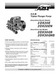
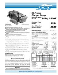
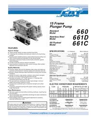
Removal of Discharge Manifold and socket head screws<br />
CAUTION: Be<strong>for</strong>e commencing with service, shut off drive (electric motor, gas or diesel engine) and turn off water supply to<br />
pump. Relieve all discharge line pressure by triggering gun or opening valve in discharge line.<br />
After servicing is completed, turn on water supply to pump, start drive, reset pressure regulating device and secondary valve, read<br />
system pressure on the gauge at the pump head. Check <strong>for</strong> any leaks, vibration or pressure fluctuations and resume operation.<br />
Inspect and service all system accessories on the same schedule as your pump.<br />
SERVICING THE VALVES<br />
Disassembly<br />
1. Remove the four (4) Socket Head Screws and Spring<br />
Washers from end of Manifold.<br />
2. Support the Discharge Manifold from the underside<br />
and tap with a soft mallet to separate from the Inlet<br />
Manifold.<br />
3. Carefully place Discharge Manifold on work surface<br />
with crankcase side up.<br />
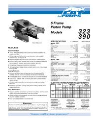
4. From the three (3) lower and shallow inlet chambers<br />
remove the Inlet Valve Adapters with front and rear<br />
O-Rings. These adapters are not held securely in position<br />
and may fall out as the Discharge Manifold is removed.<br />
5. Remove the Seats, Valves, Springs and Retainers from<br />
the inlet chambers.<br />
6. From the three (3) upper and deeper discharge<br />
chambers remove the Discharge Valve Adapters with<br />
front and rear O-Rings. These Adapters generally remain<br />
with the Discharge Manifold as it is removed.<br />
Insert two screwdrivers under the lip of the Adapter and<br />
pry the Adapter from the manifold chamber.<br />
7. Remove the Seats, Valves, Springs and Retainers from<br />
the discharge chambers.<br />
NOTE: The inlet and discharge use the same<br />
Retainers, Springs, Seats and Valves. The<br />
O-Rings and valve adapters are different. Keep<br />
parts in order as they are removed.<br />
Reassembly (Discharge)<br />
NOTE: For certain applications, apply liquid gasket to<br />
O-Ring crevices and seal surfaces. Refer to Tech<br />
Bulletin 053 <strong>for</strong> model identification.<br />
NOTE: EPDM elastomers require silicone-base<br />
lubricant.<br />
NOTE: Inlet and discharge valve parts are interchangeable.<br />
One Valve Kit is needed <strong>for</strong> complete<br />
valve change.<br />
1. Examine Spring Retainers <strong>for</strong> internal wear or breaks<br />
in the structure and replace as needed.<br />
2. Examine the Spring <strong>for</strong> fatigue or breaks and place the<br />
new Spring into the Retainer over the plastic center<br />
guide. Place the Spring Retainers in the upper deeper<br />
valve chambers. They will rest on the machined ridge<br />
in each chamber.<br />
3. Examine the Valves <strong>for</strong> wear or pitting and replace if<br />
necessary. Install Valves over Springs with concave<br />
side down.<br />
4. Examine Seat O-Rings <strong>for</strong> wear and replace. Place<br />
O-Rings on lip of retainers. Carefully square O-Rings<br />
in the upper discharge valve chamber to avoid cutting<br />
O-Ring when Seat is installed.<br />
5. Examine Seats <strong>for</strong> pitting, scale or ridges and replace if<br />
necessary. Install Seat with concave side down, so<br />
O-Ring fits snugly into groove on Seat.<br />
6. Examine both front and rear O-Rings on the Discharge<br />
Valve Adapter and replace if necessary. Lubricate O-Rings<br />
and fit into grooves on outside of spacer.<br />
7. Apply liquid gasket to the O-Ring crevices on the O.D.<br />
of Discharge Valve Adapter and carefully press into<br />
upper valve chambers in the discharge manifold with<br />
small diameter side down until Adapter snaps tightly<br />
into position.
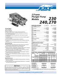
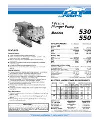
Discharge and Inlet Valve Assemblies<br />
Reassembly (Inlet)<br />
1. Examine Spring Retainers <strong>for</strong> internal wear or breaks<br />
in the structure and replace as needed.<br />
2. Insert Springs into Retainers over plastic center guide<br />
and place Spring Retainers into the lower shallow<br />
valve chambers. They will rest on the machined ridge<br />
in each chamber.<br />
3. Inspect the Valves <strong>for</strong> wear, ridges or pitting and replace<br />
if necessary. Insert Valves over the Springs with<br />
concave side down.<br />
4. Examine Seat O-Rings <strong>for</strong> wear and replace.<br />
Lubricate and place O-Rings on lip of retainers.<br />
Carefully square O-Rings in lower inlet valve chamber<br />
to avoid cutting O-Ring when Seat is installed.<br />
5. Examine Seats <strong>for</strong> pitting, scale or ridges and replace if<br />
necessary. Install Seat with concave side down, so<br />
O-Ring fits snugly into groove on Seat.<br />
6. Examine both the front and the rear O-Rings on the<br />
Inlet Valve Adapter and replace if worn. Lubricate O-Rings<br />
and fit into grooves on outside of adapters.<br />
7. Apply liquid gasket to the O-Ring crevice of the O.D. of<br />
Inlet Valve Adapter and press into lower valve chambers<br />
in the discharge manifold. Carefully square Inlet<br />
Valve Adapter into chamber to avoid cutting or extruding<br />
O-Rings.<br />
8. Rotate Crankshaft by hand so the two outside plungers<br />
are extended equally.<br />
9. Carefully replace Discharge Manifold over <strong>Plunger</strong><br />
ends aligning Discharge Valve Adapters with Inlet<br />
Manifold Chambers and press into position. Tap with<br />
a soft mallet until Inlet and Discharge Manifolds make<br />
contact.<br />
10. Replace all four (4) Washers and Socket Head Screws.<br />
Hand tighten each. Then torque per chart.
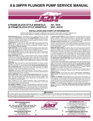
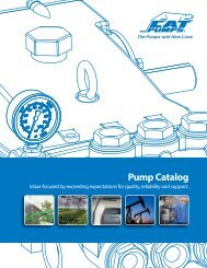
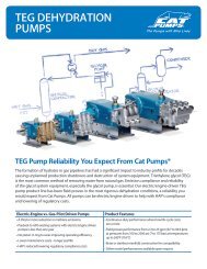
Removal of Hi and Lo-Pressure Seals<br />
SERVICING THE SEALS<br />
NOTE: All parts necessary <strong>for</strong> servicing are included<br />
in the Seal Kit.<br />
Disassembly<br />
1. With Discharge Manifold removed from the pump remove<br />
the two (2) Socket Head Screws and spring washers<br />
from end of Inlet Manifold.<br />
2. Rotate Crankshaft <strong>for</strong>ward to separate Inlet Manifold<br />
from crankcase.<br />
3. Support Inlet Manifold from underside and tap with a<br />
soft mallet to separate I.M. from Crankcase.<br />
4. With crankcase side of Inlet Manifold down remove<br />
Hi-Pressure Seals using a reverse pliers.<br />
5. Invert Inlet Manifold so crankcase side is up and with<br />
reverse pliers remove Lo-Pressure Seals.<br />
Reassembly<br />
NOTE: For certain applications, apply liquid gasket to<br />
O-Ring crevices and seal surfaces. Refer to Tech<br />
Bulletin 053 <strong>for</strong> model identification.<br />
NOTE: EPDM elastomers require silicone-base<br />
lubricant.<br />
1. Examine Lo-Pressure Seal <strong>for</strong> wear or spring failure<br />
and replace if necessary. With crankcase side of inlet<br />
manifold up, press the new Lo-Pressure Seal into the<br />
valve chamber with Garter Spring down. Carefully<br />
square seal into position.<br />
NOTE: When using alternate materials, the fit of the<br />
special materials may be snug and require gently<br />
driving the LPS into position with a cylinder of the<br />
same diameter to assure a square seating and no<br />
damage to the LPS.<br />
2. Examine Hi-Pressure Seal <strong>for</strong> wear and replace if<br />
necessary. Invert Inlet Manifold with crankcase side<br />
down and press the new seal into the manifold chamber<br />
with v-side up (metal side down) until completely<br />
seated.<br />
3. Rotate Crankshaft by hand so the two outside plungers<br />
are extended equally.<br />
4. Lubricate <strong>Plunger</strong>s and carefully slide the Inlet Manifold<br />
over the <strong>Plunger</strong>s and press into the Crankcase.<br />
5. Replace two (2) M10 Inlet Manifold Socket Head<br />
Screws, and Washers, hand tighten and then torque<br />
per chart.<br />
6. If the valves have not been serviced, examine<br />
O-Rings on both the Discharge Adapter and Inlet Valve<br />
Adapter <strong>for</strong> cuts or wear and replace as needed.<br />
Lubricate O-Rings and fit into grooves on outside of<br />
adapters.<br />
7. Carefully slip the Discharge Manifold onto <strong>Plunger</strong>s<br />
and press the exposed Discharge Valve Adapters into<br />
the Inlet Manifold chambers. Tap with a soft mallet until<br />
seated.<br />
8. Replace the four (4) M10 Discharge Manifold Socket<br />
Head Screws and Washers and hand tighten. Then<br />
torque per chart.
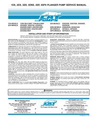
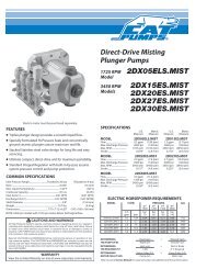
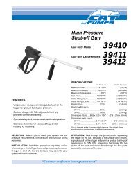
Ceramic <strong>Plunger</strong> Arrangement<br />
SERVICING THE PLUNGERS<br />
Disassembly<br />
1. Remove Discharge and Inlet Manifold as described.<br />
2. Using a wrench; loosen <strong>Plunger</strong> Retainers approximately<br />
three (3) to four (4) turns.<br />
3. Grasp Ceramic <strong>Plunger</strong> and push towards Crankcase<br />
until <strong>Plunger</strong> Retainer with stud pops out.<br />
4. Remove <strong>Plunger</strong> Retainer with O-Ring, Back-up-Ring<br />
and Gasket.<br />
5. Slip Ceramic <strong>Plunger</strong>s, Keyhole Washer and Barrier<br />
Slingers from each <strong>Plunger</strong> Rod.<br />
6. Examine Crankcase Seal <strong>for</strong> deterioration and replace<br />
if needed. Contact <strong>CAT</strong> <strong>PUMPS</strong> supplier <strong>for</strong> crankcase<br />
servicing.<br />
Reassembly<br />
1. Replace Barrier Slinger if damaged when removing<br />
and position onto <strong>Plunger</strong> Rod with concave facing<br />
out. Then examine the Keyhole Washer and place on<br />
the <strong>Plunger</strong> Rod with the slot down.<br />
2. Carefully examine Ceramic <strong>Plunger</strong> <strong>for</strong> scoring or<br />
cracks and replace if worn. Slip onto Rod. Ceramic<br />
<strong>Plunger</strong> can only be installed one direction (front to<br />
back). Do not <strong>for</strong>ce onto Rod.<br />
NOTE: Do not lubricate wicks at initial start-up.<br />
Operate <strong>for</strong> 10 to 15 minutes to allow grease from<br />
LPS to penetrate the plunger surface, then lubricate<br />
as needed.<br />
3. Examine O-Ring and Back-up-Ring on <strong>Plunger</strong><br />
Retainer and replace if worn or cut. Lubricate O-Ring<br />
<strong>for</strong> ease of installation and to avoid damage to O-Ring.<br />
First install NEW Gasket on <strong>Plunger</strong> Retainer, then<br />
O-Ring, then Back-up-Ring.<br />
4. Apply Loctite ® 242 ® to threads and install short threaded<br />
end of Stud into <strong>Plunger</strong> Retainer.<br />
5. Apply Loctite ® 242 ® to threads and thread <strong>Plunger</strong><br />
Retainer and Stud assembly with long threaded end<br />
of Stud into plunger rod. Torque per chart.<br />
Exercise caution not to over torque the <strong>Plunger</strong><br />
Retainer.<br />
6. Re-install the Seal Retainers with the slots to the top<br />
and bottom.<br />
7. Rotate Crankshaft by hand so the two outside plungers<br />
are extended equally. Lubricate O.D. of plungers.<br />
8. Carefully slip Inlet and Discharge Manifold assembly<br />
onto <strong>Plunger</strong>s and tap with soft mallet until flush with<br />
Crankcase.<br />
9. Replace the two (2) Inlet Manifold Socket Head Screws<br />
and Washers and hand tighten. Then torque per chart.<br />
10. Torque the four (4) Discharge Manifold Socket Head<br />
Screws in sequence per chart.<br />
1<br />
4<br />
SERVICING CRANKCASE SECTION<br />
1. While Manifold, <strong>Plunger</strong>s and Seal Retainers are<br />
removed, examine Crankcase Oil Seals <strong>for</strong> leaking and<br />
wear.<br />
2. Check <strong>for</strong> any signs of leaking at Bearing Covers, Rear<br />
Cover, Drain Plug or Bubble Oil Gauge.<br />
3. Check oil level and <strong>for</strong> evidence of water in oil. Change<br />
crankcase oil on a regular schedule. See Preventative<br />
Maintenance Check-List.<br />
4. Rotate Crankshaft by hand to feel <strong>for</strong> smooth bearing<br />
movement.<br />
5. Examine Crankshaft Oil Seals externally <strong>for</strong> drying,<br />
cracking or leaking.<br />
6. Contact <strong>CAT</strong> <strong>PUMPS</strong> or your local distributor if crankcase<br />
service is required. Refer to Tech Bulletin 035.<br />
See <strong>Plunger</strong> <strong>Pump</strong> <strong>Service</strong> DVD <strong>for</strong> additional<br />
in<strong>for</strong>mation.<br />
Loctite and 242 are registered trademarks of the Henkel Corporation.<br />
3<br />
2
PREVENTATIVE MAINTENANCE CHECK-LIST<br />
Check Daily Weekly 50 hrs. 500 hrs.* 1500 hrs.** 3000 hrs.**<br />
Clean Filters x<br />
Oil Level/Quality x<br />
Oil Leaks x<br />
Water Leaks x<br />
Belts, Pulley x<br />
Plumbing x<br />
Initial Oil Change x<br />
Oil Change x<br />
Seal Change x<br />
Valve Change x<br />
Accessories x<br />
* If other than <strong>CAT</strong> <strong>PUMPS</strong> special custom-blend, multi-viscosity, ISO-68<br />
hydraulic oil is used, change cycle should be every 300 hours.<br />
** Each system’s maintenance cycle will be exclusive. If system per<strong>for</strong>mance<br />
decreases, check immediately. If no wear at 1500 hours, check again at 2000<br />
hours and each 500 hours until wear is observed. Valves typically require<br />
changing every other seal change.<br />
Duty cycle, temperature, quality of pumped liquid and inlet feed conditions all<br />
effect the life of pump wear parts and service cycle.<br />
** Remember to service the regulator/unloader at each seal servicing and check<br />
all system accessories and connections be<strong>for</strong>e resuming operation.<br />
Refer to DVD <strong>for</strong> additional assistance.<br />
TORQUE CHART<br />
Torque<br />
<strong>Pump</strong> Item Thread Tool Size [Part No.] in.lbs. ft.lbs. Nm<br />
<strong>Plunger</strong> Retainer 303 S.S./Brass<br />
M6<br />
<strong>Plunger</strong> Retainer 316 S.S.<br />
M11 Hex [44044] 55 4.6 6.2<br />
M6<br />
Inlet Manifold Screws<br />
M12 Hex 55 4.6 6.2<br />
M10 M8 Allen [33046] 220 18.0 24<br />
Discharge Manifold Screws<br />
M10<br />
Rear Cover/Bearing Cover Screws<br />
M8 Allen [33046] 220 18.0 24<br />
M6 M10 Hex/Phil. [25082] 50 4.0 5.4<br />
Connecting Rod Screws<br />
M7 M10 Hex [25082] 95 8.0 11<br />
Bubble Oil Gauge<br />
M28 Oil Gauge Tool [44050] 45 3.8 5<br />
Mounting Bolts<br />
M8 M13 Hex [25324] 115 9.58 13<br />
TECHNICAL BULLETIN REFERENCE CHART<br />
No. Subject Models<br />
002 Inlet Pressure VS Liquid Temperature All Models<br />
003 Power Unit Drive Packages 3P<strong>FR</strong> - 68P<strong>FR</strong>, 10<strong>FR</strong> - 60<strong>FR</strong><br />
024 Lubrication of Lo-Pressure Seals All Models<br />
033 Crankcase and Rear Cover 270, 279, 280, 290<br />
034 Servicing Crankcase Section 3<strong>FR</strong>, 4<strong>FR</strong>, 10<strong>FR</strong>, 25<strong>FR</strong><br />
035 Servicing Crankcase Section 7CP, 7P<strong>FR</strong> - 68P<strong>FR</strong><br />
036 Cylinder and <strong>Plunger</strong> Reference Chart All Models<br />
043 LPS and HPS Servicing All <strong>Plunger</strong> Models<br />
047 Blind Bearing Shaft Cover Gearbox <strong>Plunger</strong> <strong>Pump</strong>s<br />
049 Stainless Steel Hardware 3P<strong>FR</strong>7, 5P<strong>FR</strong>7, 15P<strong>FR</strong>7<br />
053 Liquid Gasket All <strong>Plunger</strong> NAB-S.S. Models<br />
064 By-Pass Hose Sizing All Unloaders/Regulators<br />
067 S.S. <strong>Plunger</strong> Retainer 3P<strong>FR</strong>, 5P<strong>FR</strong>, 7P<strong>FR</strong><br />
073 Hi-Temp HPS 2SF, 3P<strong>FR</strong>, 5P<strong>FR</strong>, 5CP, 7P<strong>FR</strong><br />
074 Torque Chart Piston and <strong>Plunger</strong> <strong>Pump</strong>s<br />
077 Oil Drain Kit All Models (except 2SF/4SF)<br />
083 Winterizing a <strong>Pump</strong> All Models<br />
095 Galling Prevention Stainless Steel Models<br />
INLET CONDITION CHECK-LIST<br />
Review Be<strong>for</strong>e Start-Up<br />
Inadequate inlet conditions can cause serious malfunctions in the best designed<br />
pump. Surprisingly, the simplest of things can cause the most severe problems<br />
or go unnoticed to the unfamiliar or untrained eye. REVIEW THIS CHECK-LIST<br />
BEFORE OPERATION OF ANY SYSTEM. Remember, no two systems are alike, so<br />
there can be no ONE best way to set-up a system. All factors must be<br />
carefully considered.<br />
INLET SUPPLY should exceed the maximum flow being delivered by the pump to<br />
assure proper per<strong>for</strong>mance.<br />
❏ Open inlet shut-off valve and turn on water supply to avoid starving the pump.<br />
DO NOT RUN PUMP DRY.<br />
❏ Temperatures above 130°F are permissible. Add 1/2 PSI inlet pressure per each<br />
degree F over 130°F. Elastomer or RPM changes may be required. See Tech<br />
Bulletin 002 or call <strong>CAT</strong> <strong>PUMPS</strong> <strong>for</strong> recommendations.<br />
❏ Avoid closed loop systems especially with high temperature, ultra-high pressure<br />
or large volumes. Conditions vary with regulating/unloader valve.<br />
❏ Low vapor pressure liquids, such as solvents, require a booster pump and C.A.T.<br />
to maintain adequate inlet supply.<br />
❏ Higher viscosity liquids require a positive head and a C.A.T. to assure adequate<br />
inlet supply.<br />
❏ Higher temperature liquids tend to vaporize and require positive heads and<br />
C.A.T. to assure adequate inlet supply.<br />
❏ When using an inlet supply reservoir, size it to provide adequate liquids to accommodate<br />
the maximum output of the pump, generally a minimum of 6-10 times the<br />
GPM (however, a combination of system factors can change this requirement);<br />
provide adequate baffling in the tank to eliminate air bubbles and turbulence; install<br />
diffusers on all return lines to the tank.<br />
INLET LINE SIZE should be adequate to avoid starving the pump.<br />
❏ Line size must be a minimum of one size larger than the pump inlet fitting. Avoid<br />
tees, 90 degree elbows or valves in the inlet line of the pump to reduce the risk of<br />
flow restriction and cavitation.<br />
❏ The line MUST be a FLEXIBLE hose, NOT a rigid pipe, and rein<strong>for</strong>ced on<br />
SUCTION systems to avoid collapsing.<br />
❏ The simpler the inlet plumbing the less the potential <strong>for</strong> problems. Keep the<br />
length to a minimum, the number of elbows and joints to a minimum (ideally no<br />
elbows) and the inlet accessories to a minimum.<br />
❏ Use pipe sealant to assure air-tight, positive sealing pipe joints.<br />
INLET PRESSURE should fall within the specifications of the pump.<br />
❏ Acceleration loss of liquids may be increased by high RPM, high temperatures,<br />
low vapor pressures or high viscosity and may require pressurized inlet and<br />
C.A.T. to maintain adequate inlet supply. DO NOT USE C.A.T. WITH SUCTION<br />
INLET.<br />
❏ Optimum pump per<strong>for</strong>mance is obtained with +20 PSI (1.4 BAR) inlet<br />
pressure and a C.A.T. <strong>for</strong> certain applications. With adequate inlet plumbing,<br />
most pumps will per<strong>for</strong>m with flooded suction. Maximum inlet pressure is 60 PSI<br />
(4 BAR).<br />
❏ After prolonged storage, pump should be rotated by hand and purged of air to<br />
facilitate priming. Disconnect the discharge port and allow liquid to pass through<br />
pump and measure flow.<br />
INLET ACCESSORIES are designed to protect against overpressurization,<br />
control inlet flow, contamination or temperature and provide ease of servicing.<br />
❏ A shut-off valve is recommended to facilitate maintenance.<br />
❏ Installation of a C.A.T. is essential in applications with stressful conditions such<br />
as high temperatures, booster pump feed or long inlet lines. Do not use C.A.T.<br />
with negative inlet pressure.<br />
❏ A stand pipe can be used in some applications to help maintain a positive head<br />
at the pump inlet.<br />
❏ Inspect and clean inlet filters on a regular schedule to avoid flow restriction.<br />
❏ A pressure transducer is necessary to accurately read inlet pressure. (Short<br />
term, intermittent cavitation will not register on a standard gauge.)<br />
❏ All accessories should be sized to avoid restricting the inlet flow.<br />
❏ All accessories should be compatible with the solution being pumped to<br />
prevent premature failure or malfunction.<br />
❏ Optional inlet protection can be achieved by installing a pressure cutoff switch<br />
between the inlet filter and the pump to shut off pump when there is no positive<br />
inlet pressure.<br />
BY-PASS TO INLET Care should be exercised when deciding the method of<br />
by-pass from control valves.<br />
❏ It is recommended the by-pass be directed to a baffled reservoir tank, with at<br />
least one baffle between the by-pass line and the inlet line to the pump.<br />
❏ Although not recommended, by-pass liquid may be returned to the inlet line of<br />
the pump if the system is properly designed to protect your pump. A PRESSURE<br />
REDUCING VALVE must be installed on the inlet line (BETWEEN THE<br />
BY-PASS CONNECTION AND THE INLET TO THE PUMP) to avoid excessive<br />
pressure to the inlet of the pump. It is also recommended that a THERMO<br />
VALVE be used in the by-pass line to monitor the temperature build-up in the<br />
by-pass loop to avoid premature seal failure.<br />
❏ A rein<strong>for</strong>ced, flexible, low pressure hose rated up to 300 PSI should be used <strong>for</strong><br />
routing by-pass back to the pump inlet.<br />
❏ Caution should be exercised not to undersize the by-pass hose diameter and<br />
length. Refer to Technical Bulletin 64 <strong>for</strong> additional in<strong>for</strong>mation on the size and<br />
length of the by-pass line.<br />
❏ Check the pressure in the by-pass line to avoid overpressurizing the inlet.<br />
❏ The by-pass line should be connected to the pump inlet line at a gentle angle of<br />
45° or less and no closer than 10 times the pump inlet port diameter<br />
e.g. 1-1/2" port size = 15" distance from pump inlet port.
Water*<br />
Flow<br />
Gal/Min<br />
HOSE <strong>FR</strong>ICTION LOSS<br />
PRESSURE DROP IN PSI PER 100 FT OF HOSE<br />
WITH TYPICAL WATER FLOW RATES<br />
Hose Inside Diameters, Inches<br />
1/4 5/16 3/8 1/2 5/8 3/4 1"<br />
0.5 16 5 2<br />
1 54 20 7 2<br />
2 180 60 25 6 2<br />
3 380 120 50 13 4 2<br />
4 220 90 24 7 3<br />
5 320 130 34 10 4<br />
6 220 52 16 7 1<br />
8 300 80 25 10 2<br />
10 450 120 38 14 3<br />
15 900 250 80 30 7<br />
20 1600 400 121 50 12<br />
25 650 200 76 19<br />
30 250 96 24<br />
40 410 162 42<br />
50 600 235 62<br />
60 370 93<br />
*At a fixed flow rate with a given size hose, the pressure drop across a given hose length<br />
will be directly proportional. A 50 ft. hose will exhibit one-half the pressure drop of a 100<br />
ft. hose. Above values shown are valid at all pressure levels.<br />
Water<br />
GPM<br />
1<br />
2<br />
3<br />
5<br />
8<br />
10<br />
15<br />
25<br />
40<br />
60<br />
80<br />
100<br />
WATER LINE PRESSURE LOSS<br />
PRESSURE DROP IN PSI PER 100 FEET<br />
Steel Pipe—Nominal Dia.<br />
1/4 3/8 1/2 3/4 1 1 1 /4 1 1 /2<br />
8.5 1.9<br />
30 7.0 2.1<br />
60 14 4.5 1.1<br />
150 36 12 2.8<br />
330 86 28 6.7 1.9<br />
520 130 43 10 3.0<br />
270 90 21 6.2 1.6<br />
670 240 56 16 4.2 2.0<br />
66 17 8.0<br />
37 17<br />
52 29<br />
210 107 48<br />
Brass Pipe—Nominal Dia.<br />
1/4 3/8 1/2 3/4 1 11 /4 11 6.0 1.6<br />
20 5.6 1.8<br />
/2<br />
40 11 3.6<br />
100 28 9.0 2.2<br />
220 62 21 5.2 1.6<br />
320 90 30 7.8 2.4<br />
190 62 16 5.0 1.5<br />
470 150 40 12 3.8 1.7<br />
39 11 5.0<br />
23 11<br />
40 19<br />
61 28<br />
Copper Tubing O.D. Type L<br />
1/4 3/8 1/2 5/8 3/4 7/8<br />
120 13 2.9 1.0<br />
400 45 10 3.4 1.3<br />
94 20 6.7 2.6<br />
230 50 17 6.1 3.0<br />
500 120 40 15 6.5<br />
180 56 22 10<br />
120 44 20<br />
330 110 50<br />
550 200 88<br />
RESISTANCE OF VALVES AND FITTINGS<br />
Nominal<br />
Pipe<br />
Size<br />
Inches<br />
Inside<br />
Diameter<br />
Inches<br />
Gate<br />
Valve<br />
Globe<br />
Valve<br />
Angle<br />
Valve<br />
45˚<br />
Elbow<br />
90˚<br />
Elbow<br />
180˚<br />
Close<br />
Ret<br />
Tee<br />
Thru<br />
Run<br />
1/2 0.622 0.41 18.5 9.3 0.78 1.67 3.71 0.93 3.33<br />
3/4 0.824 0.54 24.5 12.3 1.03 2.21 4.90 1.23 4.41<br />
1 1.049 0.69 31.2 15.6 1.31 2.81 6.25 1.56 5.62<br />
11 /4 1.380 0.90 41.0 20.5 1.73 3.70 8.22 2.06 7.40<br />
11 /2 1.610 1.05 48.0 24.0 2.15 4.31 9.59 2.40 8.63<br />
2 2.067 1.35 61.5 30.8 2.59 5.55 12.30 3.08 11.60<br />
2 1 /2 2.469 1.62 73.5 36.8 3.09 6.61 14.70 3.68 13.20<br />
3 3.068 2.01 91.5 45.8 3.84 8.23 18.20 4.57 16.40<br />
4 4.026 2.64 120.0 60.0 5.03 10.80 23.90 6.00 21.60<br />
Arriving at a total line pressure loss, consideration should then be given to<br />
pressure loss created by valves, fittings and elevation of lines.<br />
If a sufficient number of valves and fittings are incorporated in the system to<br />
materially affect the total line loss, add to the total line length, the equivalent<br />
length of line of each valve or fitting.<br />
TYPICAL RESERVOIR TANK<br />
RECOMMENDED 6 TO 10 TIMES SYSTEM CAPACITY<br />
Flexible Hose<br />
to <strong>Pump</strong><br />
FILTER<br />
→<br />
→<br />
MIN. 4"<br />
Equivalent Length of Standard Pipe in Feet<br />
Bypass Line<br />
(from regulator or unloader)<br />
Level Sensing<br />
Device<br />
→<br />
→<br />
MIN. 4"<br />
Minimum<br />
Liquid<br />
Level<br />
→<br />
Tee<br />
Thru<br />
Branch<br />
1.5 x D (Min.)<br />
Minimum Two Baffles<br />
Sealed at Bottom<br />
Supply Line<br />
T (Dia of pipe)<br />
X D<br />
→<br />
→<br />
→<br />
→<br />
Bypass Line<br />
(from regulator or<br />
unloader)<br />
Handy Formulas to Help You<br />
Q. How can I find the RPM needed to get specific GPM<br />
(Gallons Per Minute) I want?<br />
Rated RPM<br />
A. Desired RPM = Desired GPM x<br />
Rated GPM<br />
Q. I have to run my pump at a certain RPM. How do I figure<br />
the GPM I’ll get?<br />
Rated GPM<br />
A. Desired GPM = Desired RPM x<br />
Rated RPM<br />
Q. Is there a simple way to find the approximate horsepower<br />
I’ll need to run the pump?<br />
A. Electric Brake GPM x PSI (Standard 85%<br />
Horsepower Required =<br />
1460 Mech. Efficiency)<br />
Q. What size motor pulley should I use?<br />
<strong>Pump</strong> RPM<br />
A. <strong>Pump</strong> Pulley (Outer Diameter) x<br />
Motor/Engine RPM<br />
Q. How do I calculate the torque <strong>for</strong> my hydraulic drive<br />
system?<br />
A. Torque (ft. lbs.) = 3.6<br />
( )<br />
GPM x PSI<br />
RPM<br />
Avoid Cavitation Damage<br />
One or several of the conditions shown in the chart below may<br />
contribute to cavitation in a system resulting in premature wear,<br />
system downtime and unnecessary operating costs.<br />
CONDITION SOLUTION<br />
Inadequate inlet<br />
● Increase line size to the inlet port or one size<br />
line size larger<br />
Water hammering<br />
● Install C.A.T. Tube<br />
liquid acceleration/<br />
deacceleration<br />
● Move pump closer to liquid supply<br />
Rigid Inlet Plumbing ● Use flexible wire rein<strong>for</strong>ced hose to absorb<br />
pulsation and pressure spikes<br />
Excessive Elbows in<br />
Inlet Plumbing<br />
● Keep elbows to a minimum and less than 90°<br />
Excessive Liquid<br />
Temperature<br />
● Use Thermo Valve in bypass line<br />
● Do not exceed pump temperature specifications<br />
● Substitute closed loop with baffled holding tank<br />
● Adequately size tank <strong>for</strong> frequent or high<br />
volume bypass<br />
● Pressure feed high temperature liquids<br />
● Properly ventilate cabinets and rooms<br />
Air Leaks in Plumbing ● Check all connections<br />
● Use PTFE thread tape or pipe thread sealant<br />
Agitation in Supply ● Size tank according to pump output —<br />
Tank Minimum 6-10 times system GPM<br />
● Baffle tank to purge air from liquid and<br />
separate inlet from discharge<br />
(Consult<br />
Engine Mfr.)<br />
High Viscosity Liquids ● Verify viscosity against pump specifications<br />
be<strong>for</strong>e operation<br />
● Elevate liquid temperature enough to reduce<br />
viscosity<br />
● Lower RPM of pump<br />
● Pressure feed pump<br />
● Increase inlet line size<br />
Clogged Filters<br />
● Per<strong>for</strong>m regular maintenance or use clean<br />
filters to monitor build up<br />
● Use adequate mesh size <strong>for</strong> liquid and pump<br />
specifications
DIAGNOSIS AND MAINTENANCE<br />
One of the most important steps in a high pressure system is to establish a regular maintenance program. This will vary slightly with each<br />
system and is determined by various elements such as the duty cycle, the liquid being pumped, the actual specifications vs rated specifications<br />
of the pump, the ambient conditions, the inlet conditions and the accessories in the system. A careful review of the necessary inlet conditions<br />
and protection devices required be<strong>for</strong>e the system is installed will eliminate many potential problems.<br />
<strong>CAT</strong> <strong>PUMPS</strong> are very easy pumps to service and require far less frequent service than most pumps. Typically, only common tools are required,<br />
making in-field service convenient, however, there are a few custom tools, special to certain models, that do simplify the process. This service<br />
manual is designed to assist you with the disassembly and reassembly of your pump. The following guide will assist in determining the cause<br />
and remedy to various operating conditions. You can also review our FAQ or SERVICE sections on our WEB SITE <strong>for</strong> more facts or contact<br />
<strong>CAT</strong> <strong>PUMPS</strong> directly.<br />
PROBLEM PROBABLE CAUSE SOLUTION<br />
Low pressure •Worn nozzle. •Replace with properly sized nozzle.<br />
•Belt slippage. •Tighten belt(s) or install new belt(s).<br />
•Air leak in inlet plumbing. •Tighten fittings and hoses. Use PTFE liquid or tape.<br />
•Pressure gauge inoperative or not registering accurately. •Check with new gauge. Replace worn or damaged gauge.<br />
•Relief valve stuck, partially plugged or improperly adjusted. •Clean/adjust relief valve. Replace worn seats/valves and o-rings.<br />
•Inlet suction strainer (filter) clogged or improperly sized. •Clean filter. Use adequate size filter. Check more frequently.<br />
•Abrasives in pumped liquid. •Install proper filter.<br />
•Leaky discharge hose. •Replace discharge hose with proper rating <strong>for</strong> system.<br />
•Inadequate liquid supply. •Pressurize inlet and install C.A.T.<br />
•Severe cavitation. •Check inlet conditions.<br />
•Worn seals. •Install new seal kit. Increase frequency of service.<br />
•Worn or dirty inlet/discharge valves. •Clean inlet/discharge valves or install new valve kit.<br />
Pulsation •Faulty Pulsation Dampener. •Check precharge. If low, recharge, or install a new dampener.<br />
•Foreign material trapped in inlet/discharge valves. •Clean inlet/discharge valves or install new valve kit.<br />
Water leak<br />
•Under the manifold •Worn High Pressure or Lo-Pressure Seals. •Install new seal kit. Increase frequency of service.<br />
•Worn adapter o-rings. •Install new o-rings.<br />
•Into the crankcase •Humid air condensing into water inside the crankcase. •Install oil cap protector. Change oil every 3 months or 500 hours.<br />
•Excessive wear to seals. •Install new seal kit. Increase frequency of service.<br />
Knocking noise<br />
•Inlet supply •Inadequate inlet liquid supply. •Check liquid supply. Increase line size, pressurize or install C.A.T.<br />
•Bearing •Broken or worn bearing. •Replace bearing.<br />
•Pulley •Loose pulley on crankshaft •Check key and tighten set screw.<br />
Oil leak<br />
•Crankcase oil seals. •Worn crankcase oil seals. •Replace crankcase oil seals.<br />
•Crankshaft oil seals and o-rings. •Worn crankshaft oil seals or o-rings on bearing cover. •Remove bearing cover and replace o-rings and/or oil seals.<br />
•Drain plug •Loose drain plug or worn drain plug o-ring. •Tighten drain plug or replace o-ring.<br />
•Bubble gauge •Loose bubble gauge or worn bubble gauge gasket. •Tighten bubble gauge or replace gasket.<br />
•Rear cover •Loose rear cover or worn rear cover o-ring. •Tighten rear cover or replace o-ring.<br />
•Filler cap •Loose filler cap or excessive oil in crankcase. •Tighten filler cap. Fill crankcase to specified capacity.<br />
<strong>Pump</strong> runs extremely rough<br />
•Inlet conditions •Restricted inlet or air entering the inlet plumbing •Correct inlet size plumbing. Check <strong>for</strong> air tight seal.<br />
•<strong>Pump</strong> valves •Stuck inlet/discharge valves. •Clean out <strong>for</strong>eign material or install new valve kit.<br />
•<strong>Pump</strong> seals •Leaking High Pressure or Lo-Pressure seals. •Install new seal kit. Increase frequency of service.<br />
Premature seal failure •Scored plungers. •Replace plungers.<br />
•Over pressure to inlet manifold. •Reduce inlet pressure per specifications.<br />
•Abrasive material in the liquid being pumped. •Install proper filtration at pump inlet and clean regularly.<br />
•Excessive pressure and/or temperature of pumped liquid. •Check pressure and inlet liquid temperature.<br />
•Running pump dry. •DO NOT RUN PUMP WITHOUT LIQUID.<br />
•Starving pump of adequate liquid. •Increase hose one size larger than inlet port size. Pressurize and<br />
install C.A.T.<br />
•Eroded manifold. •Replace manifold. Check liquid compatibility.