Pile foundations - Duktus
Pile foundations - Duktus
Pile foundations - Duktus

Create successful ePaper yourself
Turn your PDF publications into a flip-book with our unique Google optimized e-Paper software.
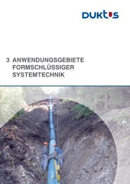
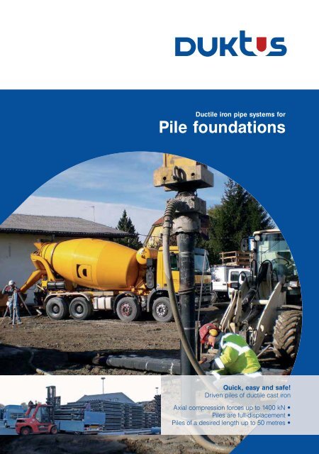
Ductile iron pipe systems for<br />
<strong>Pile</strong> <strong>foundations</strong><br />
Quick, easy and safe!<br />
Driven piles of ductile cast iron<br />
Axial compression forces up to 1400 kN •<br />
<strong>Pile</strong>s are full-displacement •<br />
<strong>Pile</strong>s of a desired length up to 50 metres •
Driven piles of ductile cast iron<br />
Safe and highly versatile foundation components<br />
The building industry needs simple and safe pre-formed driven pile systems<br />
which are suitable for a wide range of applications. The driven cast iron pile<br />
is driven into the ground to a desired length and transmits forces from the<br />
structure situated above it into the ground. The ductile pile is an economical<br />
and technically acceptable alternative to conventional methods of laying<br />
deep <strong>foundations</strong>. Carrying working loads of up to 1400 kN, the ductile pile<br />
is suitable for foundation work of almost any kind.<br />
Being economical while giving high productivity on sites which are simple<br />
to set up, this system is not only suitable for large-scale projects but can<br />
also be used at low cost on small to medium-sized building projects.<br />
The load is transmitted either by end-bearing pressure in the case of ungrouted<br />
end-bearing piles or by skin friction in the case of pressure-grouted<br />
piles.<br />
Austria – Factory enlargement in the centre of Salzburg – Pressure-grouted driven piles of ductile cast iron up to 59 m in length transmit loads of 800 kN<br />
The advantages<br />
• Sites are simple to set up because the equipment used is relatively light<br />
and easy to manoeuvre.<br />
• Corrosion resistance is high compared with structural steel.<br />
• <strong>Pile</strong> lengths can be adjusted reliably to changing soil conditions. The<br />
shaft bearing capacity can be checked while piles are being driven.<br />
• Individual pile pipes are quickly connected by frictional connections on<br />
the site itself and no special tools or welding are needed.<br />
• Installation with almost no transmitted vibration. <strong>Pile</strong>s can be installed on<br />
gap sites. Minimum spacing of pile centreline from existing buildings is<br />
40 cm.<br />
• Extremely economical. Capital costs are low and productivity is high at<br />
200-400 running metres a day.<br />
• No spoil from boring, no off-cuts and no re-machining of the heads of<br />
piles.
Highly versatile, with the<br />
environment in mind<br />
Buildings<br />
Foundations for buildings on gap sites: the<br />
manoeuvrable equipment and short completion<br />
times are a big advantage on inner-city sites.<br />
The use of pile caps of the same width as the<br />
walls means considerable savings on foundation<br />
concrete.<br />
Industrial buildings<br />
Foundations for prefabricated buildings: loads<br />
can be carried safely by piles grouped to support<br />
small pocket <strong>foundations</strong>. Highly suitable<br />
for lightweight structures with their sensitivity to<br />
settlement and especially to differential settlement.<br />
Wind loads and loads from the supporting<br />
structure are transmitted safely into the ground.<br />
Bridge-building<br />
Foundations for bridge abutments: sites are<br />
quick and easy to change over for pile driving.<br />
Moments are transmitted by pile bents and<br />
horizontal forces by raking piles.<br />
<strong>Pile</strong>-supported pipelines<br />
Foundations for pipelines: can be used in sewer<br />
and water pipeline laying to prevent unacceptable<br />
settlement in soils of low bearing capacity.<br />
Software-assisted sizing of pile-supported pipe<br />
systems.<br />
Slope stabilisation<br />
Stabilisation against slippage of slopes, embankments,<br />
ground prepared for ski runs, and so<br />
on. To provide stability, piles can be installed in<br />
vertical to near-horizontal positions to accompany<br />
construction work or as an urgent remedial<br />
measure.<br />
Silo <strong>foundations</strong><br />
Foundations for silos, tower cranes, power<br />
line pylons and radio masts: <strong>foundations</strong> are<br />
stressed in compression and tension. Structures<br />
of considerable height subject to cyclic wind<br />
loads are founded on pile bents with additional<br />
tensile reinforcement.<br />
Trench shoring<br />
To create a retaining wall in the area of an adjacent<br />
existing building. The piles are held in the<br />
soil of good bearing capacity at a point below<br />
the floor of the trench and at the head end they<br />
are connected to an anchored belt of reinforced<br />
concrete.<br />
Uplift control<br />
Foundations for sedimentation tanks, road<br />
underpasses and construction trenches at<br />
depths within the range of variation of the water<br />
table. The concrete floor is safeguarded against<br />
floating up by additional tensile reinforcement set<br />
into the concrete.<br />
Strengthening of <strong>foundations</strong><br />
Strengthening and underpinning of existing<br />
structures: inside industrial and other buildings<br />
where the working height is limited, old <strong>foundations</strong><br />
are strengthened or new <strong>foundations</strong> are<br />
laid retrospectively to carry additional loads or<br />
for underpinning.<br />
Spain – Lebrija solar energy park. 14 hectares, 3.2 MW<br />
Austria – Poysdorf-Wilfersdorf wind park. 14 Vestus V90 wind turbines, 28 MW<br />
Austria – Grimming-Therme low energy building. 500 geothermal heat probes, 22,000 m 2<br />
Italy – Noise barriers for the Brenner railway line, barriers along a 4.5 km stretch of the line<br />
Austria – Flood protection for the Leutascher Ache river, environmental upgrading of a<br />
section of the river
An approved pile system<br />
5.0 metre long pile pipes<br />
The ductile cast iron pile pipes, with a tapering spigot end and a tapering<br />
socket, are assembled into a continuous pile of a desired length.<br />
• Efficiently transportable and site logistics are simplified<br />
• Easy to handle<br />
• <strong>Pile</strong> lengths can be up to 50 metres<br />
The lengthening of the pile is performed quickly, safely and securely by means of a frictional tapered socket joint<br />
A full range of products<br />
The pile system includes all the accessories to form the heads and toes of<br />
piles, and anvils to suit any hydraulic hammer.<br />
• <strong>Pile</strong>-supported pipelines: <strong>Pile</strong>-pipe saddles for DN 200 to DN 500<br />
pipelines<br />
• Drive shoes and drive tips for grouted and ungrouted piles<br />
• Coupling sleeves for connecting shortened piles when headroom is<br />
limited<br />
European technical approval and CE marking<br />
<strong>Pile</strong> accessories to suit the nature of the load transmission and the<br />
foundation ground and supported structure<br />
Frictional socket joint<br />
The driving process and the high impact energy produce a rigid joint stiff in<br />
bending between the pile pipes.<br />
• The individual pipes can be connected quickly on the site itself<br />
• No special tools or welding work needed<br />
• Flexible adjustment to the foundation ground: assurance of correct<br />
lengthening of the pile shaft<br />
Typ<br />
Wall thickness<br />
mm<br />
Mass<br />
kg/m<br />
Moment of<br />
inertia cm 4<br />
Grouting and non-grouting anvils available for many different types of hammer<br />
Resisting<br />
moment cm 3<br />
118 7.5 21.0 399 68<br />
118 9.0 24.4 461 78<br />
118 10.6 28.0 521 88<br />
170 9.0 37.2 1,480 174<br />
170 10.6 42.6 1,693 199
Economical to use<br />
Driving equipment used is compact<br />
Even when the space available is confined, the low weight of the pile pipes<br />
to be driven means that they can be driven with a light and manoeuvrable<br />
hydraulic digger using a hydraulic double-acting hammer.<br />
• Sites are quick and easy to set up and change over<br />
• Low capital investment costs<br />
• Space required is small and driving platform requirements are modest<br />
Checking of shaft bearing capacity during driving<br />
Ungrouted and grouted piles<br />
Depending on the nature of the soil, ductile piles can be driven either<br />
ungrouted (end-bearing piles filled with concrete) or grouted (friction piles,<br />
sheathed and filled with mortar).<br />
An incision for concrete to escape through is made in the first pipe<br />
<strong>Pile</strong>s are full-displacement<br />
Each pile pipe is inserted in the tapered socket of the pipe driven previously<br />
and the pipe string is driven into the foundation ground to the final depth<br />
by displacing the soil. The projecting end is cut off precisely to the planned<br />
height.<br />
• No drilling spoil is produced hence no disposal costs<br />
• No re-machining of the pile heads<br />
• No waste: the length cut off is re-used as an initial pile pipe<br />
• No driving for redundant lengths: driving takes place in the already<br />
completed prior excavation<br />
• No change in the groundwater balance<br />
Grouting takes place simultaneously with the installation of the pile<br />
Simultaneous pressure grouting<br />
A widened driving shoe creates a cavity around the entire circumference of<br />
a pile pipe as it is driven. As the driving progresses, a pump continuously<br />
grouts this cavity with mortar.<br />
• Short installation times<br />
• High productivity of 200 to 400 m a day<br />
• <strong>Pile</strong> lengths are optimised by the compacting of the soil and the<br />
interengagement with it<br />
• No re-grouting required<br />
The projecting end is cut to the planned height and re-used as a starting section for the next pile
Proven over more than 3 million metres<br />
Check on base bearing capacity<br />
The pile pipes are available in two diameters, 118 mm and 170 mm, and<br />
in wall thicknesses from 7.5 mm to 10.6 mm. They are generally filled or<br />
grouted with concrete of strength class C20/25 or C25/30.<br />
• Sized to Austrian Technical Regulation ONR 22567<br />
• Corrosion rate does not have to be considered for mortar-sheathed<br />
grouted piles<br />
• Safety factor of 1.5 for the cast iron material<br />
Safety on the site<br />
The soil is displaced sideways and therefore no need for drilling spoil to be<br />
flushed out with high-pressure water or air. The manual work is confined to<br />
minor physical exertions which are not dangerous.<br />
• Less risk of accidents<br />
Type<br />
Wall<br />
thickness<br />
mm<br />
<strong>Pile</strong><br />
Bearing capacity in kN<br />
<strong>Pile</strong> + concrete<br />
(C20/25)<br />
<strong>Pile</strong> + concrete<br />
(C25/30)<br />
118 7.5 521 660 678<br />
118 9.0 616 747 764<br />
118 10.6 715 837 854<br />
170 9.0 910 1,212 1,253<br />
170 10.6 1.062 1,352 1,391<br />
Table 1: Maximum permitted base bearing capacity (kN) for pressure grouted piles, and for<br />
non-pressure-grouted piles up to corrosiveness level AS1 under Austrian standard B 5013-1<br />
(no corrosion rate).<br />
Type<br />
Wall<br />
thickness<br />
mm<br />
<strong>Pile</strong><br />
Bearing capacity in kN<br />
<strong>Pile</strong> + concrete<br />
(C20/25)<br />
<strong>Pile</strong> + concrete<br />
(C25/30)<br />
118 7.5 465 604 622<br />
118 9.0 561 692 709<br />
118 10.6 660 782 799<br />
170 9.0 831 1,133 1,174<br />
170 10.6 982 1,272 1,311<br />
Table 2: Maximum permitted base bearing capacity (kN) for non-pressure-grouted piles – corrosiveness<br />
level AS2 under Austrian standard B 5013-1 (corrosion rate of 1.5 mm at diameter for 100 years).<br />
Type<br />
Wall<br />
thickness<br />
mm<br />
<strong>Pile</strong><br />
Bearing capacity in kN<br />
<strong>Pile</strong> + concrete<br />
(C20/25)<br />
<strong>Pile</strong> + concrete<br />
(C25/30)<br />
118 7.5 375 514 532<br />
118 9.0 471 602 619<br />
118 10.6 570 692 709<br />
170 9.0 699 1,001 1,042<br />
170 10.6 851 1,141 1,180<br />
Table 3: Maximum permitted base bearing capacity (kN) for non-pressure-grouted piles – corrosiveness<br />
level AS3 under Austrian standard B 5013-1 (corrosion rate of 4.0 mm at diameter for 100 years).<br />
Check on shaft bearing capacity<br />
Ductile piles are driven to the final depth, which is established from penetration<br />
resistance. The penetration resistance which is measured is used as a<br />
criterion for stopping the driving and for the bearing capacity of the ground<br />
strata which are entered.<br />
• <strong>Pile</strong> length can be matched to the soil conditions actually encountered<br />
• Shaft bearing capacity can be checked during driving<br />
• Skin friction values of up to 150 kN/m 2<br />
• Correlation exists between driving times and permitted skin friction values<br />
Driving with little vibration<br />
Measurements made on sensitive sites have repeatedly shown that the<br />
installation process is an environmentally gentle one. The vibration levels<br />
measured were always only a fraction of the permitted levels.<br />
• <strong>Pile</strong>s can be driven with centrelines down to 40 cm from existing<br />
structures<br />
Driving times<br />
s/m<br />
Compactness<br />
of ground<br />
DPH<br />
(N10)<br />
SPT<br />
(N30)<br />
Skin friction<br />
values kN/m 2<br />
Pressed Very loose 0-2 30 Very dense >30 >50 150<br />
Table 4: Correlation between driving time, number of impacts in driving tests and associated skin<br />
friction values for non-cohesive soils (safety factor of 2.0 included).<br />
Driving times<br />
s/m<br />
Stiffness of<br />
ground<br />
DPH<br />
(N10)<br />
SPT<br />
(N30)<br />
Skin friction<br />
values kN/m 2<br />
Pressed Mushy – – 0<br />
Pressed Soft 0-1 0-2 0<br />
5-10 Soft to stiff 2-5 3-8 (20)<br />
10-15 Stiff 5-7 8-15 (40)<br />
15-30 Semi-firm 8-15 16-30 70<br />
>30 Firm >15 >30 100<br />
Table 5: Correlation between driving time, number of impacts in driving tests and associated skin<br />
friction values for cohesive soils (safety factor of 2.0 included).
Made of a modern material<br />
Corrosion resistance<br />
The high carbon and silicon contents and the annealing skin produced by<br />
the production process give ductile cast iron (spheroidal graphite cast iron)<br />
greater corrosion resistance as compared with structural steel.<br />
High impact resistance<br />
The addition of magnesium to the molten iron shortly before it is centrifugally<br />
cast and the post-annealing process which follows endow the cast<br />
iron with its ductility and strength.<br />
• Can be driven with powerful hydraulic hammers<br />
• No risk of over-stressing during the driving<br />
Pipes are produced from recycled iron and are themselves fully recyclable<br />
Industrial pre-forming<br />
As an accompaniment to production, continuous checks are made on<br />
quality to the relevant standards. The quality assurance process covers the<br />
chemical composition, the mechanical properties and the dimensions.<br />
• Quality monitored to EN standards, ISO 9001 certification<br />
• Large stock: even short delivery times are possible<br />
The formation of spheroidal graphite confers high corrosion resistance and impact resistance<br />
Material is 100% recycled<br />
The metal charge for the smelting of the basic iron consists entirely of raw<br />
materials from the recycling industry, laminated transformer and other<br />
cores, carefully sorted steel scrap and other recycled material.<br />
<strong>Pile</strong> production from molten iron by the centrifugal casting process<br />
EN-GJS-400-10 spheroidal graphite cast iron<br />
Compression strength 900 MPa<br />
Tensile strength 420 MPa<br />
0.2% offset yield stress 300 MPa<br />
Modulus of elasticity 170,000 MPa<br />
Density 7,050 kg/m3 Accompanying monitoring of the quality of each individual pipe
<strong>Duktus</strong> S.A.<br />
GERMANY<br />
Manfred Schmied<br />
M +49 (0) 171 30 58 547<br />
manfred.schmied@duktus.com<br />
Innsbrucker Straße 51<br />
6060 Hall in Tirol<br />
Austria<br />
T +43 (0) 5223 503-215<br />
www.duktus.com<br />
© • 006 • 02/10 • e 2 500 • DBH<br />
Your contacts<br />
AUSTRIA &<br />
SWITZERLAND<br />
Thomas Aumüller<br />
M +43 (0) 664 44 30 723<br />
thomas.aumueller@duktus.com<br />
INTERNATIONALLY<br />
Jérôme Coulon<br />
M +43 (0) 664 85 64 195<br />
jerome.coulon@duktus.com