
Create successful ePaper yourself
Turn your PDF publications into a flip-book with our unique Google optimized e-Paper software.
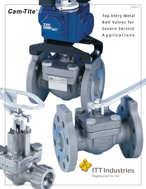
<strong>Cam</strong>-Tite ®<br />
Top Entry Metal<br />
Ball Valves for<br />
Severe Service<br />
Applications<br />
CTBV-01
CONTENTS<br />
Page<br />
Introduction ....................................................................................................................................1<br />
Quality Assurance....................................................................................................................2 – 3<br />
Design Features ......................................................................................................................4 – 5<br />
Seat Options ............................................................................................................................6 – 7<br />
Ceramic Ball ..................................................................................................................................8<br />
Bonnet Options ........................................................................................................................8 – 9<br />
Special Services ..........................................................................................................................10<br />
Dry Chlorine Service....................................................................................................................11<br />
Special Installations<br />
Welding Without Disassembly ................................................................................................12<br />
Drain Bosses ..........................................................................................................................12<br />
Extended Stems ....................................................................................................................12<br />
Handle Options ............................................................................................................................13<br />
Pressure/Temperature Ratings ............................................................................................14 – 15<br />
Flow Coefficients (Cvs) ................................................................................................................16<br />
Valve Operating Torques ..............................................................................................................17<br />
Actuated Service ..........................................................................................................................18<br />
Actuator Torques ..........................................................................................................................19<br />
Dimensions, Weights, Parts Lists ........................................................................................20 – 25<br />
Actuator Mounting Dimensions ............................................................................................26 – 29<br />
Service Guide ......................................................................................................................30 – 37<br />
Installation & Maintenance Instructions ..............................................................................38 – 40<br />
Exploded Views............................................................................................................................41<br />
Compliance with National Standards ..........................................................................................42<br />
Materials Standards ....................................................................................................................42<br />
Ordering Information & Figure Numbers..............................................................................43 – 45<br />
Metric Conversion Table ..............................................................................................................46<br />
Conversion Factors ......................................................................................................................47<br />
Product Specification Worksheet ................................................................................................48<br />
Terms & Conditions of Sale................................................................................Inside Back Cover
Headquartered in Lancaster, PA, ITT Industries<br />
Engineered Valves' product line is as extensive<br />
as the many industries that we serve. Our<br />
45 year heritage stems from diaphragm valves,<br />
of which we are the recognized leader.<br />
Through the years, our product offering has<br />
grown extensively. Our corrosion handling<br />
expertise has provided the impetus for the<br />
design of quarter-turn valve products like our<br />
<strong>Cam</strong>-Tite ® Ball Valve.<br />
INTRODUCTION<br />
By developing products such as the <strong>Cam</strong>-Tite<br />
that address specific problems encountered in<br />
industry, we continue to expand our commitment<br />
to remain a leader in flow control.<br />
The performance of our products is surpassed<br />
only by the care taken in the many facets of their<br />
manufacturing. Excellence in quality assurance,<br />
product reliability, and product safety will always<br />
remain of paramount concerns.<br />
1
Quality Assurance Measures<br />
Every Valve Is Tested<br />
Each and every standard <strong>Cam</strong>-Tite Ball Valve<br />
receives a seat and hydrostatic shell test prior to<br />
shipment. In accordance with MSS-SP-72 and<br />
ANSI B16.34, this testing includes an 80 psi air<br />
under water seat test and a hydrostatic shell test<br />
conducted at 1.5 times the cold working<br />
pressure (CWP) rating of the valve. Any visible<br />
leakage indicated by the above test<br />
procedures is cause for rejection. With valves<br />
prepared for special services, such as dry chlorine,<br />
alternate testing measures have been<br />
designed to assure product performance.<br />
As further assurance of valve quality, other<br />
testing methods such as mass spectrometer or<br />
halogen leak testing are available upon<br />
customer request.<br />
Every Valve Is Inspected<br />
Multiple inspections during the machining of<br />
component parts and during assembly insure<br />
the high standards of quality for which the<br />
<strong>Cam</strong>-Tite Ball Valve is noted. Final assembly<br />
inspection is preceded by various work-inprogress<br />
dimensional checks and assembly<br />
process inspections.<br />
Every Valve Is Tagged<br />
A computer generated stainless steel tag is<br />
affixed to each <strong>Cam</strong>-Tite Ball Valve, pinned to<br />
the body. The first line designates the<br />
configuration number, which automatically<br />
correlates information unique to the pressure<br />
class of the valve; its size; body, seat, and seal<br />
materials; and other data specific to the valve.<br />
The second line of the tag contains the original<br />
order number which is linked to the production<br />
traveler for the valve. This traveler contains information<br />
relating to the dates on which the valve<br />
was assembled, tested, inspected, and finally<br />
shipped.<br />
This tag is important documentation to protect<br />
you from field modified or bogus products.<br />
2<br />
Valve<br />
Configuration<br />
Number<br />
ITT Order Number<br />
Maximum Seat<br />
Temperature<br />
Rating<br />
Ball/Stem<br />
Material<br />
Seat Material
Quality Assurance Measures<br />
Computer Aided Design (CAD)<br />
CAD systems enhance engineering capabilities and<br />
streamline the process of product modifications and<br />
new product design.<br />
Modernized Production Capabilities<br />
Modern, computer controlled manufacturing equipment,<br />
coupled with focused production cells and methods, assure<br />
high standards in product quality. These methods also result<br />
in speed and flexibility across the entire scheduling and<br />
manufacturing cycle.<br />
Radiography<br />
To augment visual inspection, x-ray examination of major<br />
castings is utilized for volumetric evaluation.This option is<br />
available upon customer request.<br />
Liquid Penetrant Examination<br />
Surface discontinuities in castings can be evaluated through<br />
liquid (dye) penetrant evaluations. This quality assurance<br />
method is available upon customer request.<br />
Positive Material Identification<br />
Taking the guesswork out of material identification, an alloy<br />
analyzer can provide additional verification of the chemical<br />
composition of metallic components. Available upon request.<br />
3
Beveled Edge Ball Design<br />
The Geometry Is The Difference<br />
First introduced in 1979, the <strong>Cam</strong>-Tite Ball<br />
Valve has developed a reputation for performance<br />
unequaled by conventional floating ball<br />
designs. The difference is in the ball, where<br />
around the port edge the spherical surface is<br />
cut away, forming a bevel that passes<br />
completely around the port opening. This is one<br />
Conventional Floating<br />
Ball Design<br />
<strong>Cam</strong>-Tite ®<br />
Design<br />
Benefits<br />
• Minimizes pressure on seats to reduce cold<br />
flow and extend seat life.<br />
• Eliminates the problem of “breakaway torque”<br />
in valves that must rest in the open position<br />
for long periods.<br />
4<br />
of the most important design features of the<br />
<strong>Cam</strong>-Tite Ball Valve since it is the difference in<br />
the effective distance across the beveled<br />
surfaces and the distance across the spherical<br />
surface that actually energizes the seat when<br />
the valve is closed.<br />
• Assures positive sealing regardless of line<br />
pressure or pressure differential.<br />
• Eliminates seat damage caused by the<br />
leading edge of the ball port cutting into the<br />
seat as the ball closes.
Superior Stem Seal Design<br />
Low Torque Makes The Difference<br />
Hex nut<br />
Belleville washers<br />
Washer/Rotational Stop<br />
Gland ring<br />
Upper<br />
stem seal<br />
Lower<br />
stem seal<br />
Blow-out<br />
proof stem<br />
Most stem seals would work well if their only job<br />
was to contain the fluid or gas in the piping<br />
system. However, stem seals must also serve<br />
as bearings and hold the stem in alignment.<br />
High operating torques resulting in high lateral<br />
loading cause premature stem seal failure in<br />
conventional ball and plug valve designs. The<br />
<strong>Cam</strong>-Tite Ball Valve is by design a low torque<br />
valve, thereby minimizing lateral loading on the<br />
stem seals. In addition, the <strong>Cam</strong>-Tite stem seals<br />
are located further apart, closer to the ends of<br />
the stem, reducing the effects of lateral loading.<br />
<strong>Cam</strong>-Tite Ball Valve Seal Assembly<br />
Features and Benefits<br />
• Low operating torque reduces lateral loads on<br />
stem seals for superior performance.<br />
• Blow-out proof stem with special attention<br />
given to surface finish.<br />
• Upper and lower seals provide balanced<br />
loading of stem seals<br />
• Standard belleville spring washers provide<br />
constant "live load" on stem seals, assuring a<br />
tight seal under varying service parameters.<br />
5
<strong>Cam</strong>-Tite Seat Design<br />
Refer to pages 14-15 for pressure/temperature data.<br />
PTFE Seats and Seals<br />
All standard PTFE seats and seals are<br />
manufactured using unfilled, unpigmented PTFE.<br />
Virgin PTFE provides excellent resistance to the<br />
most aggressive chemicals and can handle<br />
media at both elevated and semi cryogenic<br />
temperatures. Having no filler material, PTFE<br />
components are commonly specified for<br />
applications where attack of an added filler<br />
could occur. Typical applications would be<br />
fluorine based chemicals which would attack<br />
glass or highly oxidizing media which would<br />
deteriorate graphite. Virgin PTFE is commonly<br />
used in <strong>Cam</strong>-Tite Ball Valves specified for hydrofluoric<br />
acid and fluorine gas service.<br />
<strong>Cam</strong>-Tite Ball Valves utilizing virgin PTFE seats<br />
and seals have a temperature range of -50°F to<br />
450°F (-45°C to 232°C).<br />
Reinforced PTFE Seats and<br />
Seals<br />
For applications that require higher temperature<br />
resistance and improved hardness, the<br />
<strong>Cam</strong>-Tite can be supplied with reinforced PTFE<br />
(RTFE) seats and stem seals. These components<br />
are glass reinforced and offer a temperature<br />
6<br />
range of -60°F to 520°F (-51°C to 271°C),<br />
dependent upon process pressure conditions.<br />
Firesafe Seats and Seals<br />
For applications involving flammable fluids, the<br />
<strong>Cam</strong>-Tite Ball Valve is available with seat and<br />
seals designated Firesafe. Most commonly supplied<br />
as reinforced PTFE, Firesafe seats incorporate<br />
secondary metal-to-metal seat rings and<br />
a special back seal for normal seat operation.<br />
Stem seals combine the fire resistance of<br />
graphite with a reinforced PTFE bearing. <strong>Cam</strong>-<br />
Tite Ball Valves equipped with these components<br />
meet the requirements of API 607 (3 rd or<br />
4 th edition depending on valve configuration).<br />
UHMWP Seat and Seal<br />
Components<br />
Ultrahigh molecular weight (high density)<br />
polyethylene offers abrasion resistance and<br />
wear resistance far superior to that of PTFE.<br />
Seats and seals of UHMWP provide exceptional<br />
service in high cycle applications. The material<br />
has a practical temperature limit of 200 degrees F<br />
(93°C).
PEEK Seat and Seal<br />
Components<br />
PEEK is a tough high temperature engineered<br />
thermoplastic offering broad chemical<br />
resistance, excellent recovery from deformation,<br />
a high degree of dimensional stability, and<br />
exceptional resistance to hydrolysis. PEEK has<br />
outstanding abrasion resistance and is not<br />
sensitive to dynamic fatigue.<br />
G2000 PEEK<br />
Chemical<br />
Since G2000 PEEK is a virgin crystalline<br />
polymer, its resistance to chemical attack is<br />
excellent. G2000 PEEK is recommended for<br />
most environments other than strong oxidizers.<br />
It is compatible with numerous acids, bases,<br />
and aliphatic and aromatic hydrocarbons.<br />
Steam<br />
Unlike most thermoplastics, G2000 PEEK will<br />
not hydrolize and is recommended for use in<br />
steam service and other high-temperature<br />
aqueous processes.<br />
Nuclear<br />
G2000 PEEK offers excellent resistance to<br />
embrittlement when exposed to gamma<br />
radiation. This resistance is maintained in both<br />
acid and alkali media.<br />
G3000 PEEK<br />
G3000 PEEK combines the basic properties of<br />
the G2000 PEEK with that of carbon graphite<br />
and PTFE fillers, yielding a seating material with<br />
greater stability at higher temperatures and<br />
significantly reduced seating torque. Due to its<br />
filled content, G3000 PEEK is an excellent<br />
choice for high temperature applications,<br />
having a maximum temperature capability of<br />
550°F (288°C).<br />
Table 1<br />
Comparison of typical physical properties<br />
G3000 G2000 PTFE<br />
Property PEEK PEEK PTFE Filled<br />
Specific Gravity 1.48 1.32 2.20 2.19<br />
Hardness (Shore) D85 D85 D50-55 D50-60<br />
Tensile Strength (psi) 17,000 14,500 4000 2000<br />
Tensile Elongation(%) 5 35 300 200<br />
Flexural Strength (psi) 30,500 16,000 No break -<br />
Flexural Modulus (psi) 1.45M 550,000 90,000-<br />
Shear Strength (psi)<br />
100,000 -<br />
@ 100F - 12,000 2800 3400<br />
@ 200F - 11,000 1900 2750<br />
@ 300F 7,750 9,000 1700 2500<br />
@ 400F - 6,500 - -<br />
@ 500F<br />
Impact Strength<br />
- 3,800 - -<br />
Notched IZOD 9 1.6- 2.7<br />
Tensile (ft-lbs/in)<br />
Rockwell "D" Scale<br />
- - 30-200 -<br />
7
Ceramic Ball<br />
The <strong>Cam</strong>-Tite ceramic ball is an<br />
advanced engineering oxide<br />
ceramic, magnesia-partially<br />
stabilized zirconia (Mg-PSZ)<br />
which has extremely high<br />
strength and fracture toughness.<br />
Features:<br />
• Corrosion resistant*<br />
• Impervious to gases<br />
• Impact resistant<br />
• Withstands high temperature<br />
• High thermal shock resistance<br />
• Impervious to build-up on the ball<br />
• Excellent choice where ferric chloride build-up is a problem<br />
The ceramic ball can be used with any combination of the available<br />
stem and body materials for the <strong>Cam</strong>-Tite Ball Valve.<br />
Caged Bonnet Option<br />
The patented “Caged Bonnet” was specifically<br />
designed to meet the needs of those hazardous<br />
applications where a quick and easy turnaround<br />
during scheduled maintenance is required. The<br />
uniquely designed caged bonnet assembly<br />
allows the repair and replacement of all internal<br />
components simply by removing the bonnet<br />
bolts and lifting off the bonnet assembly.<br />
The caged device is available on all bonnet configurations<br />
(standard, extended, severe service<br />
and bellows) in both nuclear and commercial<br />
configurations. The device utilizes a captured<br />
(caged) metal saddle that holds the ball, seat<br />
rings, seats, grounding springs and cover gasket<br />
(nuclear model only) in place. This device<br />
allows the removal and replacement of all components<br />
utilizing one subassembly.<br />
*Consult factory for specific applications.<br />
8<br />
Caged bonnet shown on a standard bonnet<br />
U.S. Patent 5, 152,502
Bonnet Options<br />
Extended Bonnet<br />
<strong>Cam</strong>-Tite Ball Valves can be furnished with<br />
extended bonnets for higher temperature or<br />
semi-cryogenic services. The extended bonnet<br />
allows the valve to be wrapped with insulation<br />
without interference from the hand lever and is<br />
interchangeable with the standard bonnet. This<br />
arrangement raises the stem seal further away<br />
from the flowing fluid, thereby reducing the<br />
effects of the temperature extremes. The stem<br />
is supported to minimize the possibility of galling<br />
or stem leakage. The extended bonnet permits<br />
the packing nut to extend beyond the valve<br />
insulation, thereby permitting stem seal<br />
adjustment without disturbing the insulation.<br />
Severe Service Bonnet<br />
The severe service bonnet option was specifically<br />
designed to meet the needs of those<br />
difficult applications where a true stuffing box is<br />
preferred. This design utilizes the extended<br />
bonnet as the primary component maintaining<br />
the conventional bottom stem seal, augmented<br />
by stacked Chevron V-ring packing at the top.<br />
The addition of an optional lantern ring and<br />
bonnet tap provides for the insertion of<br />
compatible lubricants into the packing, inert gas<br />
padding, or leak detection. Available in ANSI<br />
Class 150 through 600, the severe service<br />
bonnet option brings a modular approach to the<br />
stem sealing system of the <strong>Cam</strong>-Tite Ball Valve.<br />
Bellows Stem Seal<br />
<strong>Cam</strong>-Tite Ball Valves are also available with a<br />
bellows stem seal. This stem seal device,<br />
manufactured by Kerotest Manufacturing Corp.,<br />
provides a hermetic stem seal via a unique<br />
quarter-turn bellows design.<br />
The interface design for the bellows stem seal<br />
to the <strong>Cam</strong>-Tite Ball Valve was a joint effort<br />
between Engineered Valves and Kerotest in<br />
which the bellows assembly becomes integral<br />
to the bonnet of the valve. This allows for<br />
disassembly should replacement of internal<br />
components be required. The device can also<br />
be easily actuated. Bellows stem seals are<br />
available in ANSI Class 150 and 300 in a variety<br />
of materials.<br />
9
The Trusted Name For Severe Services<br />
Anhydrous HF Acid Service<br />
Numerous years of field application experience<br />
has lead to a recommended construction for<br />
<strong>Cam</strong>-Tite Ball Valves in anhydrous hydrofluoric<br />
acid. With a variety of body materials to choose<br />
from, valves prepared for HF service normally<br />
incorporate inconel 600 bonnet bolting,<br />
Oxygen Service<br />
<strong>Cam</strong>-Tite Ball Valves can be prepared for<br />
oxygen service. These valves are subjected to<br />
rigid procedures to insure that they are free from<br />
all burrs, chips, and dirt. They are specially<br />
assembled, cleaned, tested and packaged.<br />
Vacuum Service<br />
The Standard <strong>Cam</strong>-Tite Ball Valve is suitable for<br />
vacuum services down to 20 microns absolute.<br />
For vacuum conditions below 20 microns<br />
absolute high vacuum valves can be supplied.<br />
High vacuum service valves are manufactured<br />
with special attention to seat and seal<br />
tolerances and finishes and are specially<br />
cleaned and packaged. These valves have<br />
10<br />
Since 1979 the <strong>Cam</strong>-Tite Ball Valve has<br />
become a performance leader in tough-tohandle<br />
services. The combination of the<br />
patented sealing arrangement and the superior<br />
stem seal design has ushered the <strong>Cam</strong>-Tite<br />
into services where its design superiority has<br />
proven itself over plug valves and conventional<br />
floating ball type valves. Among the services<br />
where <strong>Cam</strong>-Tite Ball Valves have emerged as<br />
the solution are the following:<br />
•<br />
Dry Chlorine<br />
• Phosgene<br />
Anhydrous HF<br />
•<br />
•<br />
•<br />
Anhydrous Ammonia<br />
Anhydrous HCL<br />
•<br />
• PCL3 • Steam<br />
• VOCs High Vacuum<br />
inconel 718 belleville washers, a stainless steel<br />
rotational stop (in applicable sizes), and virgin<br />
PTFE seats and seals. Additionally, all HF<br />
valves are specially assembled, cleaned, and<br />
tested. Specify "Prepared for HF Service" using<br />
code "HF" in the valve configuration number.<br />
Valves prepared for oxygen are lubricated with<br />
DuPont Krytox ® GPL 206 unless otherwise<br />
specified. Order valves "Prepared for Oxygen<br />
Service" using "OX" in the configuration number.<br />
leakage rates less than 1 x 10 -7 STD. CC/Sec as<br />
verified by a mass spectrometer test. Specify<br />
valves "Prepared for High Vacuum Service"<br />
using code "VAC" in the configuration number.<br />
See pages 43-45 for additional ordering<br />
information for <strong>Cam</strong>-Tite Ball Valves prepared for<br />
the above special services.
The Proven Leader in Dry Chlorine<br />
In dry chlorine service, valves must be capable<br />
of absolute shutoff while maintaining piping<br />
system integrity (no stem seal leakage). For<br />
cost-effectiveness, they must also offer long<br />
service life. Simple enough, yet the punishing<br />
nature of chlorine handling has defeated many<br />
types of chlorine valves and forced users to<br />
accept compromises in performance and safety.<br />
Such compromises are no longer necessary.<br />
Positive Relief<br />
In accordance with the Chlorine Institute<br />
Pamphlet No. 6, all dry chlorine ball valves must<br />
be equipped to relieve excess pressure in the<br />
ball cavity toward the direction of high pressure.<br />
This is an important safety feature, ensuring that<br />
excess pressure in a closed valve will bleed off<br />
harmlessly. <strong>Cam</strong>-Tite Ball Valves prepared for<br />
dry chlorine service are equipped with a positive<br />
vent in the valve body as opposed to competitive<br />
designs that rely on self-relieving seats or vents<br />
through the ball or plug. Experi-ence has proven<br />
that self-relieving seats do not provide predictable<br />
performance. Placing the vent in the<br />
body eliminates the possibility of installing a<br />
vented ball or plug backwards. A positive body<br />
vent is the only way to provide predictable,<br />
repeatable safety relief.<br />
Note: <strong>Cam</strong>-Tite Ball Valves supplied with vented<br />
bodies are considered unidirectional with<br />
regards to shut-off.<br />
Valve Body Vent For Positive Pressure Relief<br />
Thousands of installed <strong>Cam</strong>-Tite valves are<br />
demonstrating their superiority, based on three<br />
important features:<br />
• Patented Ball Design – Assures zero leakage<br />
through the valve.<br />
• Superior Stem Seals – Prevents leakage to<br />
the atmosphere.<br />
• Positive Valve Body Vent<br />
Chlorine Valve Preparation<br />
Preparation in accordance with the Chlorine<br />
Institute Pamphlet 6 includes:<br />
• A relief vent in the body to bypass the<br />
upstream seat.<br />
• A cast arrow on the body to indicate the<br />
direction of pressure tightness.<br />
• Special cleaning of all valve components.<br />
• Special testing for seat tightness and relief<br />
port venting.<br />
• Special packaging and marking.<br />
<strong>Cam</strong>-Tite Ball Valves for dry chlorine service<br />
are usually supplied with cast carbon steel<br />
(ASTM A216 Gr. WCB) bodies, monel ball and<br />
stem, and reinforced PTFE seats, seals and<br />
cover gasket. Other materials, including alloy 20,<br />
hastelloy, and ceramic are commonly used in<br />
chlorine services and are available as required.<br />
When ordering valves "Prepared for Dry<br />
Chlorine Service", specify code "CLV" in the<br />
configuration number.<br />
11
Welding Without Disassembly<br />
<strong>Cam</strong>-Tite Ball Valves can be welded into the<br />
pipeline without disassembly provided certain<br />
procedures and precautions are followed. The<br />
valve must be in the open position during welding<br />
and should remain open until it cools to<br />
ambient temperature. Welding procedures in<br />
accordance with Section IX of the ASME Boiler<br />
and Pressure Vessel Code should be utilized. In<br />
addition, a Tempilstik (350 degrees F for PTFE<br />
and RTFE seats and seals or 200 degrees F for<br />
UHMWP seats and seals) must be used to monitor<br />
the temperature at the seat/gasket area. This<br />
Drilled, Tapped And Plugged Drain Bosses<br />
All <strong>Cam</strong>-Tite Ball Valves have an integrally cast<br />
drain boss on the bottom side of the body. This<br />
drain boss can be drilled, tapped, and plugged if<br />
draining of the valve cavity is required. The standard<br />
drilling is 1/4" NPT on 1/2" through 2" sizes<br />
and 1/2" NPT on 3" through 6" sizes. Carbon<br />
steel valves are furnished with ASTM A193 GR<br />
Stem Extensions<br />
The <strong>Cam</strong>-Tite Ball Valve can be supplied with a<br />
variety of designs to support applications which<br />
require extended stems. Stem extensions can<br />
be provided in carbon steel and stainless steel<br />
12<br />
is the area in line with the body/cover flange as<br />
shown above. Welding should be controlled such<br />
that the maximum temperature in this area<br />
remains below that of the rated Tempilstik. A<br />
tremendous amount of time and trouble associated<br />
with the dismantling and reassembly of<br />
welded valves is avoided, but more importantly,<br />
the integrity of the factory hydrostatic and seat<br />
testing is maintained when following these procedures.<br />
See page 42 for weld end machining standards.<br />
B7 plugs while stainless steel valves are furnished<br />
with ASTM A193 GR B8 plugs. (Consult<br />
the factory for specifications of drain plugs supplied<br />
on other body materials.) Specify valves<br />
"Prepared with Tapped and Plugged Drain Port"<br />
using code "D" in the configuration number<br />
when ordering.<br />
materials of construction and can be specified in<br />
a wide range of lengths for complete versatility.<br />
See pages 43-45 for information on ordering<br />
stem extensions for <strong>Cam</strong>-Tite valves.
Oval Safety Handwheels<br />
Oval safety handwheels are available on<br />
<strong>Cam</strong>-Tite Ball Valves 1/2" through 2". These<br />
handwheels are used where the standard hand<br />
levers could be accidentally bumped open or<br />
closed. The oval safety handwheels are either<br />
cast carbon steel or cast stainless steel. The<br />
Spring Return Handle Options<br />
The <strong>Cam</strong>-Tite Ball Valve can be supplied with<br />
either a manual spring return handle (dead<br />
man's handle) or a fire-safe fusible linked spring<br />
return handle for safety shut-off of manually<br />
operated valves.<br />
Chain Operator Options<br />
The <strong>Cam</strong>-Tite Ball Valve can be provided with a<br />
T-handle and chain for operation in services<br />
where access to the valve is limited. The<br />
T-handle operator can be supplied for<br />
installation in either vertical or horizontal<br />
pipelines and is available in both carbon steel<br />
and stainless steel construction.<br />
oval shape provides quick, easy identification of<br />
valve position. Specify "Prepared with Oval<br />
Safety Handwheel" using code "HD2" (carbon<br />
steel) or code "HD3" (stainless steel) in the<br />
configuration number.<br />
DIMENSIONS (INCH)<br />
Valve Size A B C<br />
1 /2" - 1" 5.0 2.03 3.0<br />
11 /2" 6.5 2.03 4.0<br />
2" 6.5 2.03 4.0<br />
DIMENSIONS (MM)<br />
1 /2" - 1" 127 52 76<br />
11 /2" 165 52 102<br />
2" 165 52 102<br />
Lock Out Device Option<br />
OSHA 1910.147 requires that valves in certain<br />
applications have a method of being locked out<br />
in the closed position to prevent unauthorized<br />
opening. The <strong>Cam</strong>-Tite Ball Valve can be<br />
supplied with a locking device which will lock the<br />
valve in either the open or closed position. The<br />
standard locking device is constructed of<br />
stainless steel and can be provided on any of<br />
the optional bonnet designs. Specify "Prepared<br />
with Locking Device" using code "LDS" in the<br />
configuration number for the valve.<br />
See pages 43-45 for additional ordering<br />
instructions for <strong>Cam</strong>-Tite valves prepared with<br />
the above handle options.<br />
13
Pressure/Temperature Ratings<br />
Class 150<br />
Flanged, Butt Weld<br />
Cold Working Pressure (PSIG)<br />
Carbon Steel – WCB 285<br />
Stainless Steel – CF8M, CF3M 275<br />
Alloy 20 – CN7M 230<br />
Monel M-35-1 230<br />
Hastelloy CW-6M 290<br />
Titanium – B367 Gr C3 265<br />
Class 150-300<br />
Screwed, Socket Weld<br />
Class 300<br />
Flanged, Butt Weld<br />
Cold Working Pressure (PSIG)<br />
Carbon Steel – WCB 740<br />
Stainless Steel – CF8M, CF3M 720<br />
Alloy 20 – CN7M 600<br />
Monel M-35-1 600<br />
Hastelloy CW-6M 750<br />
Titanium – B367 Gr C3 695<br />
14
Pressure/Temperature Ratings<br />
Class 600<br />
Flanged, Butt Weld<br />
Screwed, Socket Weld<br />
Cold Working Pressure (PSIG)<br />
Carbon Steel – WCB 1480<br />
Stainless Steel – CF8M, CF3M 1440<br />
Alloy 20 – CN7M 1200<br />
Monel M-35-1 1200<br />
Hastelloy CW-6M 1500<br />
Titanium – B367 Gr C3 1390<br />
Note: Consult factory for pressure/temperature<br />
recommendations for 3" and larger<br />
Class 600 fire-safe seats.<br />
15
Flow Coefficients (Cv)<br />
Cv = Flow of water in U.S. gallons per minute through the valve with a one psi pressure drop.<br />
Class 150 Flanged and Butt Weld<br />
Degrees<br />
Open From 10° 20° 30° 40° 50° 60° 70° 80° 90°<br />
Closed<br />
1 /2" – – 0.1 0.3 0.9 1.4 2.2 3.5 8.4<br />
3 /4" – 0.2 1.2 2.2 3.7 5.4 8.0 17.0<br />
1" – – 0.2 1.1 2.5 4.67.612.8 30.0<br />
11 /2" – – 1.0 3.0 5.5 11.0 17.5 33.5 73.0<br />
2" – 0.5 3.0 6.5 11.5 21.0 39.0 81.5 160.5<br />
3" – 0.5 3.7 12.4 22.9 42.4 81.5 181.0 355.0<br />
4" 1.1 7.8 26.1 48.4 89.7 172.5 383.4 751.6<br />
6" – – – – – – – – 1500<br />
Class 300 Flanged and Butt Weld<br />
Degrees<br />
Open From 10° 20° 30° 40° 50° 60° 70° 80° 90°<br />
Closed<br />
1 /2" – 0.1 0.3 0.7 1.2 2.1 3.8 8.4<br />
3 /4" – – 0.2 0.8 1.62.8 5.0 9.5 18.2<br />
1" – – 0.2 1.0 2.4 4.68.0 15.631.6<br />
11 /2" – 1.0 2.5 5.5 10.0 17.5 29.0 51.0 80.0<br />
2" – 1.0 3.0 6.5 13.5 22.0 39.0 72.0 163.0<br />
3" – 2.5 8.4 17.9 34.5 57.5 99.2 180.3 360.5<br />
4" – 5.3 17.8 37.9 73.0 121.7 209.9 381.6763.3<br />
6" – – – – – – – – 1500.5<br />
Class 600 Flanged and Butt Weld<br />
Degrees<br />
Open From 10° 20° 30° 40° 50° 60° 70° 80° 90°<br />
Closed<br />
1 /2" – – 0.1 0.3 0.8 1.3 2.2 3.5 8.5<br />
3 /4" – – 0.2 0.9 1.9 3.4 5.68.2 17.0<br />
1" – – 0.2 0.8 1.9 3.8 7.0 14.2 28.4<br />
11 /2" – – 0.5 3.5 9.5 17.0 31.0 55.0 81.0<br />
2" – 0.9 3.0 6.0 11.5 21.0 39.0 87.0 163.0<br />
3" – 1.4 4.7 11.2 28.1 51.1 94.6197.1 365.0<br />
4" – 2.9 9.9 23.659.1 107.4 198.9 414.5 767.5<br />
Screwed and Socket Weld – All Classes<br />
Degrees<br />
Open From 10° 20° 30° 40° 50° 60° 70° 80° 90°<br />
Closed<br />
1 /2" – – 0.1 0.2 0.7 1.2 2.1 3.68.4<br />
3 /4" – – 0.2 0.7 1.62.9 5.0 8.5 17.0<br />
1" – – 0.5 0.7 2.0 3.8 6.8 12.5 30.8<br />
11 /2" – 1.0 2.5 5.0 9.5 15.5 24.5 45.0 78.4<br />
2" – 1.0 3.0 6.0 11.5 21.0 38.5 76.5 158.5<br />
3" – 2.9 8.4 16.8 32.3 53.9 96.3 181.7 349.5<br />
Note: Consult factory for recommendations on valves intended for throttling or modulating services.<br />
16
Valve Operating Torques<br />
The actual amount of torque required to operate<br />
a valve is dependent upon many variables, such<br />
as line pressure, temperature, type of fluid, and<br />
frequency of operation. The following tables are<br />
based on the maximum breakaway/closing<br />
PRESSURE DROP ACROSS VALVE<br />
SIZE 275 PSIG 740 PSIG 1000 PSIG<br />
1 3 /2", /4", 1"<br />
1 1 75 in-lb 75 in-lb 75 in-lb<br />
/2" 85 in-lb 85 in-lb 85 in-lb<br />
2" 175 in-lb 175 in-lb 175 in-lb<br />
3" 435 in-lb 435 in-lb 450 in-lb<br />
4" 525 in-lb 770 in-lb 925 in-lb<br />
6" 1270 in-lb 1615 in-lb N/A<br />
PRESSURE DROP ACROSS VALVE<br />
SIZE 275 PSIG 740 PSIG 1000 PSIG<br />
1 3 /2", /4", 1"<br />
1 1 105 in-lb 105 in-lb 105 in-lb<br />
/2" 110 in-lb 110 in-lb 110 in-lb<br />
2" 220 in-lb 220 in-lb 235 in-lb<br />
3" 590 in-lb 590 in-lb 640 in-lb<br />
4" 695 in-lb 895 in-lb 1195 in-lb<br />
6" 1355 in-lb 1730 in-lb N/A<br />
PRESSURE DROP ACROSS VALVE<br />
SIZE 275 PSIG 740 PSIG 1480 PSIG<br />
1 3 /2", /4", 1"<br />
1 1 195 in-lb 195 in-lb 195 in-lb<br />
/2" 240 in-lb 265 in-lb 265 in-lb<br />
2" 340 in-lb 375 in-lb 695 in-lb<br />
3" 1285 in-lb 1345 in-lb 1705 in-lb<br />
4" 1400 in-lb 1610 in-lb 2665 in-lb<br />
6"<br />
N/A N/A N/A<br />
Consult factory for stem materials not listed above.<br />
torque requirements of a <strong>Cam</strong>-Tite Ball Valve<br />
handling a clean, particle free liquid. For valves<br />
used in heavy liquids, high particulate fluids,<br />
gases, or sub zero temperatures, consult the<br />
factory for actual torque recommendations.<br />
UNFILLED PTFE FIRESAFE REINFORCED PTFE<br />
REINFORCED PTFE (RTFE) UHMW POLYETHYLENE<br />
G3000 PEEK G2000 PEEK<br />
Maximum Allowable Stem Torques<br />
PRESSURE DROP ACROSS VALVE<br />
SIZE 275 PSIG 740 PSIG 1000 PSIG<br />
1 3 /2", /4", 1"<br />
1 1 115 in-lb 115 in-lb 115 in-lb<br />
/2" 150 in-lb 150 in-lb 160 in-lb<br />
2" 325 in-lb 325 in-lb 350 in-lb<br />
3" 735 in-lb 750 in-lb 1700 in-lb<br />
4" 890 in-lb 1545 in-lb 2535 in-lb<br />
6" 2300 in-lb 2650 in-lb N/A<br />
PRESSURE DROP ACROSS VALVE<br />
SIZE 275 PSIG 740 PSIG 1000 PSIG<br />
1 3 /2", /4", 1"<br />
1 1 95 in-lb 95 in-lb 95 in-lb<br />
/2" 120 in-lb 120 in-lb 120 in-lb<br />
2" 260 in-lb 260 in-lb 260 in-lb<br />
3" 620 in-lb 620 in-lb 785 in-lb<br />
4" 795 in-lb 795 in-lb 1080 in-lb<br />
6" 1555 in-lb 1555 in-lb N/A<br />
PRESSURE DROP ACROSS VALVE<br />
SIZE 275 PSIG 740 PSIG 1480 PSIG<br />
1 3 /2", /4", 1"<br />
1 1 195 in-lb 195 in-lb 195 in-lb<br />
/2" 250 in-lb 250 in-lb 250 in-lb<br />
2" 375 in-lb 555 in-lb 960 in-lb<br />
3" 1400 in-lb 1595 in-lb 2500 in-lb<br />
4" 2055 in-lb 2775 in-lb 3960 in-lb<br />
6"<br />
N/A N/A N/A<br />
The following torque values represent the maximum allowable torque which can be applied to a<br />
specific valve size and stem material before permanent damage to the stem occurs. These values<br />
should not be exceeded when sizing power actuators for application with the <strong>Cam</strong>-Tite Ball Valve.<br />
SIZE 316 ss Monel<br />
STEM MATERIAL<br />
Alloy 20 Hastelloy 276 Inconel 625<br />
1 /2" - 1" 460 in-lb 390 in-lb 275 in-lb 275 in-lb 275 in-lb<br />
11 /2" 590 in-lb 505 in-lb 355 in-lb 355 in-lb 355 in-lb<br />
2" 1040 in-lb 1110 in-lb 785 in-lb 785 in-lb 785 in-lb<br />
3" 4660 in-lb 4300 in-lb 2510 in-lb 2940 in-lb 4300 in-lb<br />
4" 4800 in-lb 5760 in-lb 3360 in-lb 3940 in-lb 5760 in-lb<br />
6" 14500 in-lb 29100 in-lb 17000 in-lb 19900 in-lb 29100 in-lb<br />
17
Actuated Service<br />
By virtue of its low torque design, the <strong>Cam</strong>-Tite Ball Valve is an inexpensive and easy valve to actuate.<br />
The low torque feature allows the valve to be actuated with a much smaller and more cost<br />
effective actuator. This means you have the superior performance of the <strong>Cam</strong>-Tite Ball Valve at a lower<br />
package cost than with conventional ball or plug valves.<br />
When it comes to actuated "isolation" valves,<br />
the <strong>Cam</strong>-Tite is truely unique. To begin with,<br />
since there is virtually no load on the seats<br />
when the valve rests in the open position, the<br />
seats remain in prime condition waiting to be<br />
called into service. Since there is no<br />
"breakaway" when moving from the open to<br />
closed positions, the actuator is set into motion<br />
without opposing load. Only when the valve is<br />
essentially closed does the valve operating<br />
torque reach design peak. It is nice to know<br />
that when peak load is reached, the valve is<br />
already closed.<br />
Engineered Valves can supply actuator packages utilizing the Compact rack and pinion actuator or any<br />
other actuator suited to your needs. Actuator packages are completely assembled and tested by<br />
Engineered Valves to meet our highest standards of quality.<br />
Typical actuator mounting is accomplished either by utilizing the flange pads on flanged end<br />
valves or by replacing the cover bolts with studs and double nuts on socket, threaded and buttweld<br />
configurations. Both methods allow the removal of the actuator without disturbing the body/cover seal.<br />
If field mounting of actuation is necessary, the<br />
following guidelines should be followed:<br />
1. Use flange pad mounting when available. If<br />
not, then machined studs must be used –<br />
not threaded rod.<br />
2. It is recommended that if the bonnet is<br />
loosened, then the cover gasket should be<br />
replaced.<br />
3. Bolting torques shown on page 40 should<br />
be followed.<br />
4. The rotational stop pin in the cover (3", 4" and 6") should<br />
be removed. Open/closed positioning should<br />
be accomplished by proper adjustment of<br />
the actuator travel stops.<br />
See pages 26-29 for actuator mounting details.<br />
18
Actuator Output Torques (in-lb)<br />
1A – Inner spring (H15 only)<br />
1B – Outer spring (H15 only)<br />
2 – Two springs (H15 only)<br />
2A – Inner and middle springs<br />
2B – Inner and outer springs<br />
2C – Middle and outer springs<br />
3 – All three springs<br />
ACTUATOR<br />
SIZE<br />
15<br />
20<br />
25<br />
30<br />
35<br />
45<br />
60<br />
75<br />
No. OF<br />
SPRINGS<br />
1A<br />
1B<br />
2<br />
2A<br />
2B<br />
2C<br />
3<br />
2A<br />
2B<br />
2C<br />
3<br />
2A<br />
2B<br />
2C<br />
3<br />
2A<br />
2B<br />
2C<br />
3<br />
2A<br />
2B<br />
2C<br />
3<br />
2A<br />
2B<br />
2C<br />
3<br />
2A<br />
2B<br />
2C<br />
3<br />
OPERATING PRESSURE (PSI)<br />
SPRING<br />
TORQUE<br />
40 60 80 100 120 MAXIMUM<br />
AIR AIR AIR AIR AIR AIR AIR AIR AIR AIR SPRG SPRG<br />
ST<strong>AR</strong>T END ST<strong>AR</strong>T END ST<strong>AR</strong>T END ST<strong>AR</strong>T END ST<strong>AR</strong>T END ST<strong>AR</strong>T END<br />
53<br />
78<br />
169<br />
284<br />
487<br />
913<br />
2261<br />
3869<br />
26<br />
27<br />
46<br />
92<br />
86<br />
115<br />
437<br />
927<br />
Double Acting<br />
ACTUATOR<br />
OPERATING PRESSURE (PSI)<br />
SIZE<br />
20 40 60 80 100 120<br />
15 39 79 119 160 199 239<br />
20 79 158 238 318 398 478<br />
25 160 320 480 640 800 960<br />
30 267 537 806 1074 1343 1611<br />
35 471 941 1412 1882 2353 2824<br />
45 907 1813 2719 3626 4532 5438<br />
60 2149 4298 6446 8595 10744 12893<br />
75 3765 7530 11295 15060 18825 22590<br />
92<br />
69<br />
158<br />
129<br />
331<br />
278<br />
556<br />
486<br />
962<br />
836<br />
1828<br />
1576<br />
4431<br />
3867<br />
7332<br />
6313<br />
64<br />
18<br />
104<br />
55<br />
200<br />
98<br />
351<br />
221<br />
538<br />
284<br />
985<br />
482<br />
2499<br />
1355<br />
4538<br />
2585<br />
133<br />
109<br />
85<br />
244<br />
215<br />
191<br />
165<br />
502<br />
449<br />
419<br />
371<br />
847<br />
773<br />
703<br />
634<br />
1465<br />
1339<br />
1212<br />
1068<br />
2798<br />
2546<br />
2295<br />
2043<br />
6730<br />
6166<br />
5602<br />
5040<br />
11700<br />
10681<br />
9661<br />
8642<br />
103<br />
56<br />
8<br />
187<br />
138<br />
97<br />
60<br />
366<br />
264<br />
207<br />
116<br />
629<br />
499<br />
369<br />
239<br />
1027<br />
773<br />
520<br />
266<br />
1929<br />
1425<br />
919<br />
414<br />
4734<br />
3590<br />
2447<br />
1303<br />
8454<br />
6501<br />
4552<br />
2600<br />
171 140<br />
147 93<br />
123 45<br />
322 262<br />
293 214<br />
269 173<br />
243 136<br />
659 518<br />
606 416<br />
576 359<br />
528 268<br />
1106 885<br />
1036 755<br />
966 625<br />
897 495<br />
1927 1474<br />
1801 1220<br />
1674 967<br />
1548 713<br />
3686 2789<br />
3434 2285<br />
3183 1779<br />
2931 1274<br />
8836 6776<br />
8272 5632<br />
7708 4489<br />
7146 3345<br />
15390 12031<br />
14371 10078<br />
13351 8129<br />
12332 6177<br />
210 178<br />
186 131<br />
162 83<br />
411 339<br />
381 290<br />
358 249<br />
331 212<br />
816 670<br />
763 568<br />
733 511<br />
685 420<br />
1369 1139<br />
1299 1009<br />
1229 879<br />
1160 749<br />
2388 1922<br />
2262 1668<br />
2135 1415<br />
2009 1161<br />
4574 3650<br />
4322 3146<br />
4071 2640<br />
3819 2135<br />
10942 8817<br />
10378 7673<br />
9814 6530<br />
9252 5386<br />
19079 15607<br />
18060 13655<br />
17040 11706<br />
16021 9754<br />
49<br />
96<br />
144<br />
115<br />
164<br />
205<br />
242<br />
242<br />
344<br />
401<br />
492<br />
391<br />
521<br />
651<br />
781<br />
761<br />
1015<br />
1268<br />
1522<br />
1516<br />
2020<br />
2526<br />
3031<br />
3431<br />
4575<br />
5718<br />
6862<br />
5853<br />
7806<br />
9755<br />
11707<br />
24<br />
48<br />
72<br />
68<br />
97<br />
121<br />
147<br />
128<br />
178<br />
208<br />
256<br />
210<br />
280<br />
350<br />
419<br />
379<br />
505<br />
632<br />
758<br />
755<br />
1007<br />
1258<br />
1510<br />
1693<br />
2257<br />
2821<br />
3383<br />
3059<br />
4078<br />
5098<br />
6117<br />
19
Dimensions, Weights, & Parts Lists<br />
Flanged Body<br />
Socket Weld & Threaded Body<br />
Butt Weld Body<br />
20<br />
1 /2" – 2" Valves<br />
NOTE:<br />
1. Body boss can be drilled, tapped, and<br />
plugged.<br />
2. End machining meets ANSI B16.5 for<br />
flanged ends.<br />
3. 1/2" & 3/4" 150 lb. class flanged bolt<br />
holes are tapped 1/2"-13 UNC class 2B. Top<br />
two holes are blind drilled and tapped.<br />
4. The design meets ANSI B16.34, MSS-SP 72<br />
& ANSI B16.10.<br />
5. Valve is shown in the open position.<br />
Clockwise rotation of stem closes<br />
the valve.
Dimensions, Weights, & Parts Lists<br />
Flanged Body<br />
Dimensions in parenthesis ( ) are millimeters.<br />
Socket Weld & Threaded Body<br />
Bill of Materials - Base Valve with Standard Cover<br />
Note: See pages 44–45 for optional materials.<br />
Butt Weld Body<br />
1 /2" – 2" Valves<br />
21
Dimensions, Weights, & Parts Lists 3", 4" and 6" Valves<br />
Flanged Body<br />
Socket Weld & Threaded Body<br />
Butt Weld Body<br />
22<br />
NOTE:<br />
1. Body boss can be drilled, tapped, and<br />
plugged.<br />
2. End machining meets ANSI B16.5 for<br />
flanged ends.<br />
3. Top two flanged bolt holes on 3" & 4"<br />
150 lb. class valves are drilled and<br />
tapped 5/8"-11 UNC class 2B. Top two<br />
flanged bolt holes on 4" 300# Class<br />
valves are drilled and tapped<br />
3/4"-10 UNC class 2B.<br />
4. The design meets ANSI B16.34, MSS-SP 72<br />
and ANSI B16.10.<br />
5. Valve is shown in the open position.<br />
Clockwise rotation of stem closes<br />
the valve.
Dimensions, Weights, & Parts Lists 3", 4" and 6" Valves<br />
Flanged Body<br />
Dimensions in parenthesis ( ) are millimeters.<br />
Note: See pages 44–45 for optional materials.<br />
Socket Weld & Threaded Body<br />
Butt Weld Body<br />
Bill of Materials - Base Valve with Standard Cover<br />
23
Dimensions<br />
Extended Bonnet Valves<br />
The basic dimensions shown above are for <strong>Cam</strong>-Tite Ball Valves with extended bonnets as described<br />
on page 9. All components with the exception of the bonnet and stem are interchangeable on valves<br />
with standard bonnets. Parts identification and materials are also consistent with the standard bonnet<br />
and are described for the various configurations on pages 20–23. For complete dimensions and<br />
materials of construction for the extended bonnet, consult the factory.<br />
24
Dimensions<br />
Severe Service Bonnet Valves<br />
The basic dimensions shown above are for <strong>Cam</strong>-Tite Ball Valves with severe service bonnets as<br />
described on page 9. All components with the exception of the bonnet, stem, and stem seals are<br />
interchangeable on valves with standard bonnets. Otherwise, parts identification and materials are consistent<br />
with the standard bonnet and are described for the various configurations on pages 20–23. For<br />
complete dimensions and materials of construction for the severe service bonnet, consult the factory.<br />
25
Actuator Mounting Dimensions — Flange Pads<br />
26
Actuator Mounting Dimensions — Bonnet Studs and<br />
Double Nuts<br />
28
Service Guide<br />
The following charts have been assembled<br />
based on experiences in actual field installations,<br />
as well as from commonly published corrosion<br />
data. Due to the many variables involved in determining<br />
the degree of compatibility between a certain<br />
material and a certain fluid, the charts must<br />
be used as a guide only, and cannot be interpreted<br />
as a guarantee. Factors such as<br />
temperature, concentration, pressure, velocity,<br />
aeration, abrasion, cavitation, flashing, etc. play<br />
an important application role in determining the<br />
suitability of any material in a particular application<br />
and must also be taken into consideration.<br />
The selection of a suitable valve body material for<br />
a particular application is much easier than the<br />
selection of other valve components such as<br />
seats, ball, stem and packing. A certain<br />
Chemicals<br />
30<br />
Carbon Steel<br />
316 Stainless Steel<br />
Body/Trim Seats/Packing<br />
Alloy 20<br />
Monel<br />
Hastelloy C<br />
EPDM<br />
PEEK<br />
Graphite<br />
PTFE<br />
Reinforced (PTFE)<br />
UHMWP<br />
amount of corrosion is sometimes acceptable on<br />
the valve body, but the seats, ball and stem materials<br />
must be chosen carefully since corrosion of<br />
these components will likely affect the sealing<br />
characteristics of the valve.<br />
In addition to the compatibility of the material to<br />
the fluid, care must be taken to select materials<br />
and designs that are capable of withstanding the<br />
actual pressures and temperatures. Consult<br />
pages 14-15 of this catalog for pressure/<br />
temperature ratings of valves with various seats.<br />
Engineered Valves cannot accept responsibility<br />
for the accuracy, currency or reliability of the<br />
information contained herein. Selection of materials<br />
is at the sole risk of the user.<br />
CONSULT FACTORY FOR SERVICES NOT LISTED.<br />
Chemicals<br />
Carbon Steel<br />
316 Stainless Steel<br />
Body/Trim Seats/Packing<br />
Alloy 20<br />
Monel<br />
Hastelloy C<br />
EPDM<br />
PEEK<br />
Graphite<br />
Acetaldehyde<br />
C A A A A B A A A A D Alcohol, Allyl<br />
A A A A A A<br />
Acetamide<br />
B B A A A A Alcohol, Amyl<br />
B A B B B A A A A A<br />
Acetate Solvents<br />
A A A A A A A A Alcohol, Benzyl<br />
A A A A<br />
Acetic Acid, Aerated<br />
D A A A A A A Alcohol, Butyl<br />
B A A A A C A A A A<br />
Acetic Acid, Air Free<br />
D A A A A A A A Alcohol, Diacetone<br />
A A A B A B A A A<br />
Acetic Acid, Crude<br />
C A A B A A A A Alcohol, Ethyl<br />
B B A B A A A A A A A<br />
Acetic Acid, Glacial<br />
D A B A A A A Alcohols, Fatty<br />
B A A A A A A<br />
Acetic Acid, Pure<br />
D A A C A A A A A C Alcohol, Furfuryl<br />
A A A<br />
Acetic Acid, 10%<br />
C A A B A B A A A A Alcohol, Isopropyl<br />
B B A B B A A A A<br />
Acetic Acid, 80%<br />
C A A B A C A A A C Alcohol, Methyl<br />
B A A A A A A A A A<br />
Acetic Acid Vapors<br />
D B C A A A A A Alcohol, Propyl<br />
B A A A A A A A A A<br />
Acetic Anhydride<br />
D B B B A C A A A A C Alumina<br />
A A A A A A A<br />
Acetone<br />
A A A A A A A A A A A Aluminum Acetate<br />
A B C B A A A A A A<br />
Acetyl Chloride<br />
C B A D A A A A Aluminum Chloride Dry C C D B B A A A A A<br />
Acetylene<br />
A A A A A A A A A A Aluminum Chloride Solution D B B A A A A A A<br />
Acrylonite<br />
A A B A A D A A A Aluminum Fluoride<br />
D C B A A A A D A<br />
Acryolontrile<br />
A A A A A A Aluminum Hydroxide<br />
D A B B B A A A A A<br />
Adipic Acid<br />
A A B B B A A Aluminum Nitrate<br />
C B C B B B A A<br />
Acid Fumes<br />
D B B C A A Alum (Aluminum<br />
Air<br />
A A A A A A B A A A<br />
Potassium Sulfate)<br />
B B C A A A A A<br />
Albumen<br />
A A<br />
Aluminum Sulfate<br />
D B B C A A A A A A<br />
A = Excellent B = Fair C = Poor D = Not Recommended<br />
PTFE<br />
Reinforced (PTFE)<br />
UHMWP
Service Guide<br />
Chemicals<br />
Amines<br />
Ammonia, Alum<br />
Ammonia,<br />
Anhydrous Liquid<br />
Ammonia, Aqueous<br />
Ammonia Gas, Hot<br />
Ammonia Liquor<br />
Ammonia Solutions<br />
Ammonium Acetate<br />
Ammonium Bicarbonate<br />
Ammonium Bromide 5°<br />
Ammonium Carbonate<br />
Ammonium Chloride<br />
Ammonium Hydroxide 28%<br />
Ammonium Hydroxide,<br />
Concentrated<br />
Ammonium Monophosphate<br />
Ammonium Monosulfate<br />
Ammonium Nitrate<br />
Ammonium Persulfate<br />
Ammonium Phosphate<br />
Ammonium Phosphate<br />
Di-basic<br />
Ammonium Phosphate<br />
Tri-basic<br />
Ammonium Sulfate<br />
Ammonium Sulfide<br />
Ammonium Sulfite<br />
Amyl Acetate<br />
Amyl Chloride<br />
Aniline<br />
Aniline Dyes<br />
Antimony Trichloride<br />
Aqua Regia (Strong Acid)<br />
Aromatic Solvents<br />
Arsenic Acid<br />
Barium Carbonate<br />
Barium Chloride<br />
Barium Cyanide<br />
Barium Hydrate<br />
Barium Hydroxide<br />
Barium Nitrate<br />
Carbon Steel<br />
316 Stainless Steel<br />
Body/Trim Seats/Packing<br />
Alloy 20<br />
Monel<br />
Hastelloy C<br />
EPDM<br />
PEEK<br />
Graphite<br />
PTFE<br />
Reinforced (PTFE)<br />
B A A B B C A A A A<br />
A A A A A A<br />
UHMWP<br />
A A A B A B A A A A<br />
A A A B B A A A A<br />
A A B B A A A A A A<br />
A A B A A A<br />
B A A B B B A A A<br />
B A B B A A A A<br />
C B B B A A A A A<br />
B B B A A A A<br />
B B B B A A A A A<br />
D C B B B A A A A A A<br />
C B A D B B A A A A<br />
C B A C B A A A A A<br />
D B B B A A<br />
A B B B A A A<br />
D A B D B A B A A A<br />
A A D B A A A<br />
D B B C A A A A A<br />
D B B C B A A A<br />
D B B C B A A A<br />
C B B B B A A A A A<br />
D B B B A A A A A<br />
C A B D B A A A<br />
C B A B A B A A A A<br />
A A B B D A A A D<br />
C B A B B C A A A A<br />
C A A A C A A A<br />
D D C B A A<br />
D B B D D D A A C<br />
C A A B D A A A<br />
D B B D B B A A A A<br />
B B B B A A A A A A<br />
C B C B A A A A A<br />
B B D B A A A<br />
A A B A A A<br />
C B A B B A A A A<br />
A A B A A<br />
Chemicals<br />
Barium Sulfate<br />
Barium Sulfide<br />
Benzaldehyde<br />
Benzene (Benzol)<br />
Benzoid Acid<br />
Beryllium Sulfate<br />
Benzyl Chloride<br />
Black Sulfate Liquor<br />
Bleaching Powders<br />
Bleaching Powder, Wet<br />
Blood (Meat Juices)<br />
Borax (Sodium Borate)<br />
Bordeaux Mixture<br />
Boric Acid<br />
Brake Fluid<br />
Brines, saturated<br />
Bromine, Dry<br />
Bromine, Wet<br />
Bromic Acid<br />
Bunker Oils (Fuel)<br />
Butadiene<br />
Butane<br />
Butyl Acetate<br />
Butylene<br />
Butyric Acid<br />
Calcium Bisulfite<br />
Calcium Carbonate<br />
Calcium Chlorate<br />
Calcium Chloride<br />
Calcium Hydroxide<br />
Calcium Hypochlorite<br />
Calcium Nitrate<br />
Calcium Phosphate<br />
Calcium Silicate<br />
Calcium Sulfate<br />
<strong>Cam</strong>phor<br />
Cane Sugar Liquors<br />
Carbolic Acid (Phenol)<br />
Carbonated Beverages<br />
Carbonated Water<br />
Carbon Bisulfide<br />
Carbon Steel<br />
316 Stainless Steel<br />
Body/Trim Seats/Packing<br />
Alloy 20<br />
Monel<br />
Hastelloy C<br />
EPDM<br />
PEEK<br />
Graphite<br />
A = Excellent B = Fair C = Poor D = Not Recommended<br />
31<br />
PTFE<br />
Reinforced (PTFE)<br />
UHMWP<br />
C A A B B A A A A<br />
C B B C A A A A A<br />
A A A B B A A A A D<br />
B B A A B D D A A A D<br />
D B B B A D A A A A<br />
B A B B A A A<br />
B B A A<br />
C B B B A A<br />
D B B D A A<br />
C B D A B A A A A<br />
A A B B A A A A<br />
C A A A A A A A A A<br />
A A A A A<br />
D B B B A B A A A A A<br />
B B B A A A<br />
D B B B A A A A A A<br />
D D B A A D D B A A D<br />
D D D D A A<br />
A A<br />
B A A A A A A D<br />
B A A C B C A A C C D<br />
B A A B A D A A A A A<br />
B A B B D A A A D<br />
A A A A D A A A A<br />
D B B B A C A A A A D<br />
D B B D B D A A A<br />
D B B B B B A A A A A<br />
B B B B B A A A<br />
C B B B A B A A A A A<br />
C B B A A A A A A A A<br />
D C B C A A<br />
B B B B A A A<br />
B B B A A A A<br />
B B B A A A<br />
C B B B B B A A A A A<br />
B C C B A A A D<br />
A A B B A A A<br />
D B A B B A A A A<br />
D B B C B A A A<br />
B A A B A A A A A<br />
B B B B D A A A D
Service Guide<br />
Chemicals<br />
Carbon Dioxide, Dry<br />
Carbon Monoxide<br />
Carbon Tetrachloride, Dry<br />
Carbon Tetrachloride, Wet<br />
Castor Oil<br />
Caustic Potash (KOH)<br />
Caustic Soda (NaOH)<br />
Cellulose Acetate<br />
Chlorinated Solvents<br />
Chlorinated Water<br />
Chlorine, Dry<br />
Chlorine, Wet<br />
Chlorine Gas, Dry<br />
Chlorobenzene, Dry<br />
Chloroform, Dry<br />
Chlorophyll, Dry<br />
Chlorosulfonic Acid, Dry<br />
Chlorosulfonic Acid, Wet<br />
Chrome Alum<br />
Chromic Acid 50%<br />
Chromium Sulfate<br />
Citric Acid<br />
Coke Oven Gas<br />
Cooking Oil<br />
Copper Acetate<br />
Copper Carbonate<br />
Copper Chloride<br />
Copper Cyanide<br />
Copper Nitrate<br />
Copper Sulfate<br />
Corn Oil<br />
Cottonseed Oil<br />
Cresol<br />
Creosote Oil<br />
Cresylic Acid<br />
Crude Oil, Sour<br />
Crude Oil, Sweet<br />
Cumeme<br />
Cupric Nitrate<br />
Cutting Oils (Water Emulsions)<br />
32<br />
Carbon Steel<br />
316 Stainless Steel<br />
Body/Trim Seats/Packing<br />
Alloy 20<br />
Monel<br />
Hastelloy C<br />
EPDM<br />
PEEK<br />
Graphite<br />
PTFE<br />
Reinforced (PTFE)<br />
UHMWP<br />
A A A A B A A A A<br />
A A A A B A A A A<br />
B A A A A D A A A A D<br />
D B B B B D A A A A D<br />
B A A A A B A A A A<br />
A A B B A A A<br />
B A A A B B A A A<br />
B B B B A A A<br />
C A A B D D A A A<br />
C A D D D A A A C<br />
B D B A A A A<br />
D D C D A A A<br />
B B A A A D D A A A D<br />
B A A B B D B A A A D<br />
B A A A B D A A A<br />
B A B B A A A<br />
B B B B A D D A D D<br />
D D D C A A<br />
B A A B B A A A A<br />
D C B C B C D A A A A<br />
D C B D B C D A A A<br />
B C B B A A A<br />
D B A B A B A A A A A<br />
B A A B D A A A<br />
B A A A D A A A<br />
D A A C B B A A A<br />
A A A A A<br />
D D D C A A<br />
A A C B A A A A<br />
D B B D B B A A A<br />
D B B C A A A A A A<br />
C B B B C A A A A<br />
C B B B C A A A A A<br />
B B D A A A D<br />
B B A B B D A A A A D<br />
C B B B D A A A A<br />
B A A B D A A A<br />
B A A A A A A A<br />
B B B B A A<br />
A A D B A A<br />
B A A A A A<br />
Chemicals<br />
Cyanide Plating Solution<br />
Cyclohexane<br />
Cyclohexanone<br />
Denatured Alcohol<br />
Detergents, Synthetic<br />
Dextrin<br />
Diacetone Alcohol<br />
Diamylamine<br />
Dibutyl Phthalate<br />
Dichloroethane<br />
Dichloroethyl Ether<br />
Diesel Oil Fuels<br />
Diethylamine<br />
Diethyl Benzene<br />
Diethylene Glycol<br />
Diethyl Sulfate<br />
Dimethyl Formamide<br />
Dimethyl Phthalate<br />
Dioxane<br />
Dipentane (Pinene)<br />
Disodium Phosphate<br />
Dowtherm<br />
Drilling Mud<br />
Dry Cleaning Fluids<br />
Drying Oil<br />
Enamel<br />
Epsom Salts (MgSo4)<br />
Ethane<br />
Ether<br />
Ethyl Acetate<br />
Ethyl Acrylate<br />
Ethylamine<br />
Ethyl Benzene<br />
Ethyl Bromide<br />
Ethyl Chloride, Dry<br />
Ethyl Chloride, Wet<br />
Ethylene<br />
Etylenediamene<br />
Ethylene Chloride<br />
Ethylene Dichloride, Dry<br />
Ethylene Dichloride, Wet<br />
Carbon Steel<br />
316 Stainless Steel<br />
Body/Trim Seats/Packing<br />
Alloy 20<br />
Monel<br />
Hastelloy C<br />
EPDM<br />
PEEK<br />
Graphite<br />
PTFE<br />
Reinforced (PTFE)<br />
UHMWP<br />
B B D B A A<br />
A A A B B D A A A A C<br />
A A B B B A A A D<br />
B A A A A A<br />
B A B B A A A A<br />
B B B B A A A A<br />
A A A A A A<br />
A A A A<br />
A A<br />
C B B D A A A<br />
B B D A A<br />
A A A A D A A<br />
A A A B C A A A<br />
B B D A A A<br />
A A B A A A A A A<br />
B B B C A A A<br />
A A B D A A A A<br />
D A A A<br />
B B B C A A A A<br />
A A D A A A<br />
B B C A A A A<br />
B A A A D A A A A<br />
B A A B A A A A<br />
B A A B A A A<br />
C B B B A A A<br />
A D A A A<br />
C B B B A A A<br />
C B B B D A A A A<br />
A A A B C A A A A D<br />
B B B B B C A A A C<br />
C A A B A C A A A<br />
A A A<br />
B A A D A A A<br />
B C B B A A A<br />
B A A B B C A A A D<br />
D B B B B B A A A A<br />
A A A A A A<br />
A A A<br />
A A B B A A A<br />
B A A A A A<br />
D C A B A A<br />
A = Excellent B = Fair C = Poor D = Not Recommended
Service Guide<br />
Chemicals<br />
Ethylene Glycol<br />
Ethylene Oxide<br />
Ethyl Ether<br />
Ethyl Silicate<br />
Ethyl Sulfate<br />
Fatty Acids<br />
Ferric Chloride<br />
Ferric Hydroxide<br />
Ferric Nitrate<br />
Ferric Sulfate<br />
Ferrous Ammonium Citrate<br />
Ferrous Chloride<br />
Ferrous Sulfate<br />
Ferrous Sulfate, Saturated<br />
Fertilizer Solutions<br />
Fish Oils<br />
Flue Gases<br />
Fluoride Salts<br />
Fluorine Gas, Dry<br />
Fluoboric Acid<br />
Fluorosilicic Acid<br />
Formaldehyde, Cold<br />
Formaldehyde, Hot<br />
Formic Acid, Cold<br />
Formic Acid, Hot<br />
Freon Gas, Dry<br />
Freon 11, MF, 112, BF<br />
Freon 12, 13, 32, 114, 115<br />
Freon 21, 31<br />
Freon 22<br />
Freon 113, TF<br />
Freon, Wet<br />
Fuel Oil<br />
Fumaric Acid<br />
Gallic Acid 5%<br />
Gas, Manufactured<br />
Gas, Natural<br />
Gas, Odorizers<br />
Gasoline, Aviation<br />
Gasoline, Leaded<br />
Gasoline, Motor<br />
Carbon Steel<br />
316 Stainless Steel<br />
Body/Trim Seats/Packing<br />
Alloy 20<br />
Monel<br />
Hastelloy C<br />
EPDM<br />
PEEK<br />
Graphite<br />
PTFE<br />
Reinforced (PTFE)<br />
UHMWP<br />
B B A B A A A A A A A<br />
B B B B A D A D A A C<br />
A A A B D A A A A<br />
B B B B A A A<br />
B B C A A A<br />
D A A B A D A A A A A<br />
D D D D A A<br />
A A A A A A<br />
D C A D B A B A A A<br />
D B A D A A A A A<br />
B B A A A A<br />
D D D D D A A A A A<br />
D B B B B A A A A A<br />
C A A B B B A A A<br />
B B B B A A A<br />
B A A A D A A A<br />
A A B D A A A<br />
B A D<br />
B A A A D A D<br />
B A A D A<br />
D B B A B C A D A<br />
A A A A B B A A A A<br />
D C B B B A A A A<br />
D B A B A A A A A<br />
D B B B B A A A A<br />
B A A A B C A A A A<br />
A A B B C A A A A<br />
A A B B A A A A A<br />
A A B B D A A A A<br />
A A B D A A A A<br />
A A B B C A A A A<br />
C B B B B D A A A<br />
B A A B D A A A D<br />
A A A<br />
D B B B B C A A A<br />
B B B A D A A A<br />
B A B A D A A A<br />
B B A B A A A<br />
A A A A A A A A D<br />
A A A B A A A A A D<br />
A A A A A D A A A A D<br />
Chemicals<br />
Gasoline, Refined<br />
Gasoline, Sour<br />
Gasoline, Unleaded<br />
Glue<br />
Glutamic Acid<br />
Glycerine (Glycerol)<br />
Glycol Amine<br />
Glycol<br />
Helium Gas<br />
Heptane<br />
Hexane<br />
Hexanol, Tertiary<br />
Hydraulic Oil, Petroleum Base<br />
Hydrazine<br />
Hydrobromic Acid<br />
Hydrochloric Acid<br />
Hydrocyanic Acid<br />
Hydrofluoric Acid, Anhydrous<br />
Hydrofluosilicic Acid<br />
Hydrogen Gas, Cold<br />
Hydrogen Gas, Hot<br />
Hydrogen Bromide Gas<br />
Hydrogen Chloride Gas, Dry<br />
Hydrogen Peroside,<br />
Concentrated<br />
Hydrogen Peroxide, Dilute<br />
Hydrogen Sulfide, Dry<br />
Hydrogen Sulfide, Wet<br />
Hypo (Sodium Thiosulfate)<br />
Illuminating Gas<br />
Ink-Newsprint<br />
Iso-Butane<br />
Iso-Octane<br />
Isopropyl Acetate<br />
Isopropyl Ether<br />
J P-4 Fuel<br />
J P-5 Fuel<br />
J P-6 Fuel<br />
Kerosene<br />
Ketones<br />
Lacquer (and Solvent)<br />
Carbon Steel<br />
316 Stainless Steel<br />
Body/Trim Seats/Packing<br />
Alloy 20<br />
Monel<br />
Hastelloy C<br />
EPDM<br />
PEEK<br />
Graphite<br />
33<br />
PTFE<br />
Reinforced (PTFE)<br />
UHMWP<br />
B A A B A D A A A D<br />
B A A C A D A A A D<br />
A A A A A A A A D<br />
A B A B A B A A A A A<br />
B A A A<br />
C A A A A A A A A A A<br />
B D D A A A<br />
C B A B A A A A A<br />
A A B A B A A A A A<br />
B A A B A D A A A A C<br />
B A A B A D A A A A D<br />
A A A A A D A A A A<br />
A A A A D A A A<br />
B B D B A A<br />
D D D D A A<br />
D D D D A A<br />
D A A C B B A A A A<br />
B B B A A D<br />
D C B B B D A A D<br />
B A A A B A A A A A<br />
B B A A B A A A A A<br />
A A<br />
D B A B A A<br />
D B B D D B A D A A C<br />
D B B D D B A C A A A<br />
B A B B B A A A A A A<br />
C B B C D B A A A A A<br />
D B B B A A A A<br />
A A A A D A A A<br />
D A A B B A A A A<br />
B B D A A A<br />
A A A A D A A A A<br />
B A D A A A A<br />
A A A B A D A A A A<br />
A A A A A A A A A<br />
A A A A A A A A A<br />
A A A A A A A A A<br />
B A A A A D A A A A C<br />
A A A A D A A A A<br />
C A A A D A A A A<br />
A = Excellent B = Fair C = Poor D = Not Recommended
Service Guide<br />
Chemicals<br />
34<br />
Carbon Steel<br />
316 Stainless Steel<br />
Body/Trim Seats/Packing<br />
Alloy 20<br />
Monel<br />
Hastelloy C<br />
EPDM<br />
PEEK<br />
Graphite<br />
PTFE<br />
Reinforced (PTFE)<br />
Lactic Acid Concentrated, Cold D A A D A B A A A A A<br />
Lactic Acid Concentrated, Hot D B A D B B A A A A A<br />
Lactic Acid Dilute Cold D A A C A B A A A A A<br />
Lactic Acid Dilute Hot<br />
D A A D B A A A A A<br />
Lactose<br />
B B B B A A A<br />
Lard Oil<br />
C B A B B A A A A A<br />
Lead Acetate<br />
D B B B B A A A A A<br />
Lead Arsenate<br />
B A A<br />
Lead Oxide<br />
A A<br />
Lead Sulfate<br />
B B B B A A A<br />
Lecithin<br />
B B B D A A<br />
Linoleic Acid<br />
B A A B D A A A<br />
Linseed Oil<br />
A A A B D A A A A A<br />
Lithium Chloride<br />
B A B B A A A A<br />
LPG<br />
Lubricating Oil<br />
B B B B D A A A A<br />
(Petroleum Based)<br />
A A A B D A A A C<br />
Lye — See Sodium Hydroxide & Potassium Hydroxide<br />
Magnesium Bisulfate<br />
B A A B B A A A A<br />
Magnesium Bisulfide<br />
B B B B A A A A<br />
Magnesium Carbonate<br />
A A B B A A A A A<br />
Magnesium Chloride<br />
C B B B A A A A A A A<br />
Magnesium Hydroxide B A A B B A A A A A A<br />
Magnesium Hydroxide, Hot B A A A B A A A A A<br />
Magnesium Oxide<br />
A A<br />
Magnesium Nitrate<br />
A A B A B A A A<br />
Magnesium Sulfate<br />
B A A B A A A A A A A<br />
Maleic Acid<br />
B B B B A D A A A A A<br />
Maleic Anhydride<br />
B B B B D A A A<br />
Malic Acid<br />
D B B B A A A A<br />
Manganese Carbonate<br />
B A A A A A<br />
Manganese Sulfate<br />
A A B B A A A A<br />
Meat Juices<br />
A A A A A A<br />
Melamine Resins<br />
C C A A A<br />
Methanol<br />
A A B D A A A<br />
Mercuric Chloride<br />
D B B D B A A A A A A<br />
Mercuric Cyanide<br />
D A A C B A A A A A A<br />
Mercurous Nitrate<br />
A A D A B A A A<br />
Mercury<br />
A A A B B A A A A A A<br />
Methane<br />
B A A B A A A A A<br />
Methyl Acetate<br />
B A A B A B A A A A<br />
UHMWP<br />
Chemicals<br />
Methyl Acetone<br />
Methylamine<br />
Methyl Bromide 100%<br />
Methyl Cellosolve<br />
Methyl Cellulose<br />
Methyl Chloride<br />
Methyl Ethyl Ketone<br />
Methylene Chloride<br />
Methyl Formate<br />
Methyl Isobutyle Ketone<br />
Mineral Oils<br />
Mine Water (Acid)<br />
Mineral Spirits<br />
Molybdic Acid<br />
Monochloroacetic Acid<br />
Monocloro Benzene, Dry<br />
Morpholine<br />
Muriatic Acid<br />
Naptha<br />
Napthalene<br />
Natural Gas, Sour<br />
Nickel Ammonium Sulfate<br />
Nickel Chloride<br />
Nickel Nitrate<br />
Nickel Sulfate<br />
Nicotinic Acid (Niacin)<br />
Nitric Acid 10%<br />
Nitric Acid 30%<br />
Nitric Acid 80%<br />
Nitric Acid 100%<br />
Nitric Acid Anhydrous<br />
Nitrobenzene<br />
Nitrocellulose<br />
Nitrogen<br />
Nitrous Acid 10%<br />
Nitrous Gases<br />
Nitrous Oxide<br />
Oil, Linseed<br />
Oil, Lubricating<br />
Oils Petroleum Refined<br />
Oils, Petroleum Sour<br />
Carbon Steel<br />
316 Stainless Steel<br />
Body/Trim Seats/Packing<br />
Alloy 20<br />
Monel<br />
Hastelloy C<br />
EPDM<br />
PEEK<br />
Graphite<br />
PTFE<br />
Reinforced (PTFE)<br />
UHMWP<br />
A A A A A A A A A<br />
B A A C B B A A A A<br />
B A B D A A A A D<br />
B A A B B B A A A<br />
A A B A A A<br />
B A A B D A A A A D<br />
A A A A B B C A A A D<br />
B A A B B D A A A A D<br />
C B A B B B A A A<br />
A A A A A<br />
B A A A D A A A A D<br />
D C C C A A<br />
B B B B A A A D<br />
A A A A A<br />
D D C D A A<br />
B B B B A A A<br />
A A B B A A A<br />
D D D D D A A<br />
B B B B A D A A A A D<br />
B B B B B D A A A A D<br />
B A A D A D A A A A A<br />
D A A C B A A A<br />
D B A B A B A A A A A<br />
D B A B A A B A A A<br />
D B A B B B A A A A A<br />
B A A A D A A A A<br />
D A A D B B A A A<br />
D A A D B B D A A A<br />
D C B D D D D A A D<br />
D A A D D D D A A D<br />
D A A D D D D A A<br />
B A A B B C C A A A D<br />
B B B B A A<br />
A A A A B A A A A A<br />
D B B D D A A A<br />
B A A D A A A A<br />
B B B D B A A A A<br />
A A A B A A<br />
A A A B A A<br />
A A A A A D A A A A<br />
B A A A A D A A A A<br />
A = Excellent B = Fair C = Poor D = Not Recommended
Service Guide<br />
Chemicals<br />
Oils Water Mixture<br />
Olaic Acid<br />
Oleic Acid<br />
Oleum<br />
Oleum Spirits<br />
Olive Oil<br />
Oxalic Acid<br />
Oxygen<br />
Ozone, Dry<br />
Ozone, Wet<br />
Paints & Solvents<br />
Palmitic Acid<br />
Palm Oil<br />
Paraffin<br />
Paraformaldehyde<br />
Paraldehyde<br />
Pentane<br />
Perchlorethylene, Dry<br />
Phenol<br />
Phosphate Ester<br />
Phosphoric Acid 10% Cold<br />
Phosphoric Acid 10% Hot<br />
Phosphoric Acid 50% Cold<br />
Phosphoric Acid 50% Hot<br />
Phosphoric Acid 85% Cold<br />
Phosphoric Acid 85% Hot<br />
Phosphoric Anhydride<br />
Phosphorous Trichloride<br />
Phthalic Acid<br />
Phthalic Anhydride<br />
Pine Oil<br />
Pitch (Bitumen)<br />
Polysulfide Liquor<br />
Polyvinyl Acetate<br />
Polyvinyl Chloride<br />
Potassium Bicarbonate<br />
Potassium Bichromate<br />
Potassium Bisulfate<br />
Potassium Bisulfite<br />
Potassium Bromide<br />
Potassium Carbonate<br />
Carbon Steel<br />
316 Stainless Steel<br />
Body/Trim Seats/Packing<br />
Alloy 20<br />
Monel<br />
Hastelloy C<br />
EPDM<br />
PEEK<br />
Graphite<br />
PTFE<br />
Reinforced (PTFE)<br />
UHMWP<br />
B A A A A A A A<br />
B B A A A A<br />
C B A B B D D A A A C<br />
B B B C B D A A D<br />
B B D D A A<br />
B A A A B A A A A A<br />
D B B B B A A A A A<br />
B A A A A A D D A A A<br />
A A A A A A D A A C<br />
C A A A A B D A A C<br />
A A A A D A A A A<br />
C B B B B A A A A<br />
C B A A D A A A A<br />
B A A A A D A A A A C<br />
B B B B D A A A<br />
B B D A A A<br />
B A A B D A A A A<br />
B A A B B D A A A<br />
D A A A A D A A A D<br />
A A A A A A A A<br />
D C B C A A<br />
D C B B A A<br />
D B B C B D A A A A<br />
D D B C B D A A A A<br />
B A B A D A A A A<br />
C B B D A A A A<br />
A A D A A A<br />
B A A B D A A A A<br />
C B B A B B A A A<br />
C B B A A A A A A<br />
B A A B D A A A D<br />
A A D A A A<br />
B A B B A A A<br />
B B B B A A A<br />
B B B B B A A A<br />
A A B A A A A<br />
A A A A A A<br />
A A B A A A<br />
D B B D B A A A<br />
D A B B B A A A A<br />
B B B B B A A A A<br />
Chemicals<br />
Potassium Chlorate<br />
Potassium Chloride<br />
Potassium Chromate<br />
Potassium Cyanide<br />
Potassium Dichromate<br />
Potassium Ferricyanide<br />
Potassium Ferrocyanide<br />
Potassium Hydroxide,<br />
Dilute Cold<br />
Potassium Hydroxide,<br />
To 70%, Cold<br />
Potassium Hydroxide,<br />
Dilute Hot<br />
Potassium Hydroxide,<br />
To 70%, Hot<br />
Potassium Iodide<br />
Potassium Nitrate<br />
Potassium Oxalate<br />
Potassium Permanganate<br />
Potassium Phosphate<br />
Potassium Phosphate,<br />
Di-basic<br />
Potassium Phosphate,<br />
Tri-basic<br />
Potassium Sulfate<br />
Potassium Sulfide<br />
Potassium Sulfite<br />
Propane Gas B<br />
Propionic Acid<br />
Propyl Alcohol<br />
Propyl Bromide<br />
Propylene Glycol<br />
Pyridine<br />
Pyrolgalic Acid<br />
Pyroligenous Acid<br />
Quinine, Sulfate, Dry<br />
R P-1 Fuel<br />
Rubber Latex Emulsions<br />
Salicyclic Acid<br />
Salt (NaCl)<br />
Salt Brine<br />
Sea Water<br />
Sewage<br />
Carbon Steel<br />
316 Stainless Steel<br />
Body/Trim Seats/Packing<br />
Alloy 20<br />
Monel<br />
Hastelloy C<br />
EPDM<br />
PEEK<br />
Graphite<br />
35<br />
PTFE<br />
Reinforced (PTFE)<br />
UHMWP<br />
B B B C B C A A A<br />
C B A B B A A A A A<br />
B B B B A A A<br />
B B B B B A A A A A<br />
C B A B B A A A<br />
C A B B B A A A A<br />
C B B A A A A A<br />
A B B A A A A A<br />
B B B A B A A A A<br />
B B B A A A A A<br />
A B B A A A A A A<br />
C B B B B B A A A<br />
B B B B B B B A A A<br />
A A A A A A<br />
B B B B B B D A A A<br />
B B B B A D A A A<br />
A A A B B B A A A<br />
A B B B B A A A<br />
B A A B A A A A A<br />
B A A C A B A A A A<br />
B A A C B A A A A A<br />
B A B A D A A A A A<br />
D B B B A A<br />
B A A A A A<br />
B A B B A A A<br />
B B B B B A A A A A<br />
B A A A A<br />
B B A B A A<br />
A B A A<br />
A A B A A A<br />
A A A A A A A<br />
B A A A A A<br />
D A B B B A A A A A<br />
C B A A A A A A A<br />
B B B B A A A A A<br />
D B B A A A A A A A<br />
C B B B B A A A A A<br />
A = Excellent B = Fair C = Poor D = Not Recommended
Service Guide<br />
Chemicals<br />
Shellac<br />
Silicone Fluids<br />
Silver Bromide<br />
Silver Cyanide<br />
Silver Nitrate<br />
Silver Plating Sol.<br />
Soap Solutions (Stearates)<br />
Sodium Acetate<br />
Sodium Aluminate<br />
Sodium Benzoate<br />
Sodium Bicarbonate<br />
Sodium Bichromate<br />
Sodium Bisulfate 10%<br />
Sodium Bisulfite 10%<br />
Sodium Borate<br />
Sodium Bromide 10%<br />
Sodium Carbonate<br />
(Soda Ash)<br />
Sodium Chlorate<br />
Sodium Chloride<br />
Sodium Chromate<br />
Sodium Citrate<br />
Sodium Cyanide<br />
Sodium Ferricyanide<br />
Sodium Fluoride<br />
Sodium Hydroxide, 20% Cold<br />
Sodium Hydroxide, 20% Hot<br />
Sodium Hydroxide, 50% Cold<br />
Sodium Hydroxide, 50% Hot<br />
Sodium Hydroxide, 70% Cold<br />
Sodium Hydroxide, 70% Hot<br />
Sodium Hypochlorite (Bleach)<br />
Sodium Hyposulfite<br />
Sodium Lactate<br />
Sodium Metaphosphate<br />
Sodium Metasilicate Cold<br />
Sodium Metasilicate Hot<br />
Sodium Nitrate<br />
Sodium Nitrite<br />
Sodium Perborate<br />
Sodium Peroxide<br />
36<br />
Carbon Steel<br />
316 Stainless Steel<br />
Body/Trim Seats/Packing<br />
Alloy 20<br />
Monel<br />
Hastelloy C<br />
EPDM<br />
PEEK<br />
Graphite<br />
PTFE<br />
Reinforced (PTFE)<br />
UHMWP<br />
A A A A A A A A<br />
B B A A A A C<br />
A A B A A A<br />
A A B A A A<br />
D A A D A B A A A<br />
A A A A<br />
A A A A A A A A<br />
C B B B B B A A A A A<br />
C A B B B B A A A A<br />
B B B A A A A A<br />
C B A B A A A A A A<br />
B B A A A<br />
D A A B B A A A A A<br />
D A B B B B A A A A A<br />
C B B B B A A A A A<br />
C B B B B A A A A<br />
B A A B B B A A A A<br />
C B B C B B B A A A<br />
C B A A B B A A A A<br />
B A B B B A A<br />
B B A A A<br />
B A A B B A A A<br />
A A B A A A A<br />
D B A B B A A A D A<br />
A A B A B A A A D A<br />
B A A A B A A D A<br />
A A A A B A A D A<br />
B A A B A A D A<br />
A A B A B A A D A<br />
B A B B B A A D A<br />
D D C D A A A A A<br />
B B B A A A<br />
A A B A A A<br />
B B B A B A A A<br />
C A A A A A A<br />
D A A A A A A A<br />
B A A B B B D A A A<br />
B B C B A B A A A<br />
B B B B B A A A A<br />
C B B B B A A A A<br />
Chemicals<br />
Sodium Phosphate<br />
Sodium Phosphate, Di-basic<br />
Sodium Phosphate, Tri-basic<br />
Sodium Polyphosphate<br />
Sodium Salicylate<br />
Sodium Silicate<br />
Sodium Silicate, Hot<br />
Sodium Stearate<br />
Sodium Sulfate<br />
Sodium Sulfide<br />
Sodium Sulfite<br />
Sodium Tetraborate<br />
Sodium Thiosulfate<br />
Soybean Oil<br />
Stannous Chloride<br />
Stannous Fluoride<br />
Starch<br />
Steam (212°F)<br />
Stearic Acid<br />
Styrene<br />
Succinic Acid<br />
Sulfate, Black Liquor<br />
Sulfate, Green Liquor<br />
Sulfate, White Liquor<br />
Sulfite Liquors<br />
Sulfonic Acid<br />
Sulfur<br />
Sulfur Chlorides<br />
Sulfur Dioxide, Dry<br />
Sulfur Dioxide, Wet<br />
Sulfur Hexafluoride<br />
Sulfur, Molten<br />
Sulfur Trioxide<br />
Sulfur Trioxide, Dry<br />
Sulfuric Acid (0-7%)<br />
Sulfuric Acid (7-40%)<br />
Sulfuric Acid (40-75%)<br />
Sulfuric Acid (75-95%)<br />
Sulfuric Acid (95-100%)<br />
Sulfurous Acid<br />
Synthesis Gas<br />
Carbon Steel<br />
316 Stainless Steel<br />
Body/Trim Seats/Packing<br />
Alloy 20<br />
Monel<br />
Hastelloy C<br />
EPDM<br />
PEEK<br />
Graphite<br />
A = Excellent B = Fair C = Poor D = Not Recommended<br />
PTFE<br />
Reinforced (PTFE)<br />
UHMWP<br />
C B B B B A A A A A<br />
C B B B B A A A A<br />
C B B B B A A A A<br />
B B B B A A A A<br />
A A A A A<br />
B B B B B A A A A A<br />
C B B B B A A A A A<br />
B A A<br />
B A A A A A A A A<br />
B B B B B A A A A<br />
A A B B B A A A A<br />
A A B A A A<br />
B B B B A A A A<br />
C A A A B A A A A A<br />
D B A C A A<br />
B B A D<br />
C B A A C A A A A A<br />
A A A B B A A A A A<br />
C B B B A B A A A A<br />
A A A B A D A A A A<br />
B B B A A<br />
C B B B B A A A<br />
C B B B A A A<br />
C B D C A A A<br />
D B D A A<br />
B B A A<br />
C B A B B A A A A A<br />
D D A B C A A A<br />
B A B B A A A A A A<br />
A B A B B A A A A<br />
A A A A D<br />
C B A D B B D A A A<br />
B B B B D A A<br />
B B B B B B D A A<br />
D B C C A A<br />
D D B C A A<br />
D D C B B A A<br />
C D B D A A<br />
C C D B A A<br />
D B B D B C A A A A<br />
B B B A A A
Service<br />
Chemicals<br />
Tall Oil<br />
Tannic Acid<br />
Tartaric Acid<br />
Tetraethyl Lead<br />
Thioglycolic Acid<br />
Toluol (Toluene)<br />
Toluene Diisocyanate<br />
Transformer Oil<br />
Tributyl Phosphate<br />
Trichlorethylene<br />
Trichloroacetic Acid<br />
Triethanolamine<br />
Triethylamine<br />
Triethylene Glycol<br />
Trisodium Phosphate<br />
Tung Oil<br />
Turpentine<br />
Urea<br />
Uric Acid<br />
Carbon Steel<br />
316 Stainless Steel<br />
Body/Trim Seats/Packing<br />
Alloy 20<br />
Monel<br />
Hastelloy C<br />
EPDM<br />
PEEK<br />
Graphite<br />
PTFE<br />
Reinforced (PTFE)<br />
UHMWP<br />
B B B B A D A A A A<br />
C B B B B B A A A A A<br />
D A A B B B A A A A<br />
C B B A A A A A<br />
B B A A<br />
A A A A A D A A A A D<br />
A A A A<br />
A A A A A A A A C<br />
A A A A B A A A<br />
B B B B A D A A A D<br />
D B B A A A C<br />
B B B A B A A A C<br />
B B A A A<br />
C B B B A A<br />
B B A B A A A A<br />
B A A C A D A A A A<br />
B B B B A D A A A A D<br />
C B B B A B A A A A A<br />
A A A A A A A<br />
Chemicals<br />
Varnish<br />
Vegetable Oils<br />
Vinegar<br />
Vinyl Acetate<br />
Vinyl Chloride, Dry<br />
Water, Deionized<br />
Water, Distilled<br />
Water, Fresh<br />
Water, Sea<br />
Water, Acid Mine<br />
Wax Emulsions<br />
White Water<br />
Xylene (Xylol), Dry<br />
Zinc Acetate<br />
Zinc Chloride<br />
Zinc Bromide<br />
Zinc Hydrosulfite<br />
Zinc Sulfate<br />
Carbon Steel<br />
316 Stainless Steel<br />
Body/Trim Seats/Packing<br />
Alloy 20<br />
Monel<br />
Hastelloy C<br />
EPDM<br />
PEEK<br />
Graphite<br />
37<br />
PTFE<br />
Reinforced (PTFE)<br />
UHMWP<br />
C A A A A D A A A A A<br />
B A A B A D A A A<br />
D A A B A A A A A A A<br />
B B B A A A A A A<br />
A B B B A A<br />
D A A A A A<br />
D A A A A B A A A A A<br />
C A A A A B A A A A A<br />
D B B A A A<br />
D B D C A A A A A A<br />
A A A A A A<br />
C B B C A A<br />
B A A A A D A A A A D<br />
B A A<br />
D D A B A A<br />
B B B A B A A A<br />
A A A B A A A A<br />
D B A B A A A A A A A<br />
A = Excellent B = Fair C = Poor D = Not Recommended
<strong>Cam</strong>-Tite Ball Valve Operating Instructions<br />
Warning<br />
ITT Industries valves and valve actuators are designed and manufactured using good workmanship and materials,<br />
and they meet all applicable industry standards. These valves are available with components of various materials, and<br />
they should be used only in services recommended in our product catalog or by a company valve engineer.<br />
Misapplication of the product may result in injuries or property damage. A selection of valve components of the<br />
proper materials consistent with the particular performance requirements is important for proper application. Examples<br />
of the misapplication or misuse of ITT Industries products include use in an application in which the<br />
pressure/temperature rating is exceeded or failure to maintain the valve as recommended.<br />
If the valve exhibits any indication of leakage, do not operate. Isolate the valve and either repair or replace it.<br />
Installation/Operating Instructions<br />
1. This valve can be installed in any position consistent with good piping practice.<br />
2. If this valve has been furnished with a means for relieving body cavity pressure (i.e. a cavity vent), an arrow on the<br />
exterior of the valve indicates the direction of pressure tightness. Note: Vented valves are unidirectional.<br />
3. Prior to installation, inspect valve for shipping damage.<br />
4. If this valve is weld end, it may be welded into the pipeline without disassembly provided certain procedures and<br />
precautions are taken. The valve should be in the "open" position during welding and should remain open until it<br />
cools to ambient temperature. Welding procedures in accordance with Section IX of the ASME Boiler and Pressure<br />
Vessel Code should be utilized. In addition, a 350°F Tempilstik (for PTFE and RTFE seats and seals) or a 200°F<br />
Tempilstik (for UHMWP seats and seals) must be used to monitor the temperature of the seat/gasket area. Page<br />
12 shows the location on the valve body where the Tempilstik marks should be placed. This is the area in line with<br />
the body/cover flange. Welding should be controlled to maintain this area below 350°F or 200°F as noted above.<br />
If valves are furnished with other than PTFE, RTFE, or UHMWP seats/seals, contact the factory for recommended<br />
welding procedures. (See Page 12 of this brochure for additional details.)<br />
5. Prior to installation or system pressurization, tighten the stem seal nut in accordance with the torques listed in<br />
Chart #1. CAUTION: Do not back off stem seal nut while the valve is pressurized.<br />
6. Install the operating handle on the valve stem. Insure that the handle is sitting flush with the top of the packing nut<br />
and that the handle posts ( 1 /2"–2") are aligned with the groove pin travel stop to assure proper rotation of the<br />
handle. Tighten hex jam nut and handle screw ( 1 /2"–2" sizes) or tighten handle screw only (3"–6" sizes).<br />
7. Prior to installation or system pressurization, evenly tighten all cover bolting using the cross-cross method in<br />
accordance with the torques listed in Chart #2. CAUTION: Do not loosen cover bolts while the valve is<br />
pressurized.<br />
8. If necessary, repeat steps 5, 6, and 7 approximately 24 hours after system reaches operating temperature and<br />
pressure.<br />
9. Refer to the exploded view on page 41 of this brochure for proper parts identification. Always utilize factory<br />
authorized replacement parts.<br />
10. Good operating procedure requires periodic inspection of valves and replacement of necessary parts to ensure<br />
proper valve function.<br />
11. NOTE: Valves showing through leakage or high operating torque may be damaged. DO NOT use excessive force<br />
or cheater bars to operate valve. Disassemble valve, inspect components, and replace damaged parts.<br />
CAUTION: Before attempting removal/repair, always cycle valve with system pressure isolated to relieve<br />
excess pressure which may be trapped in body cavity.<br />
Maintenance Instructions — Cover Gasket Repair<br />
1. Periodically inspect condition of external valve components. Replace all parts showing excessive wear or corrosion.<br />
2. If cover gasket leaks, immediately tighten cover bolting as described under Installation Instructions, Item 7. If<br />
tightening cover bolting does not stop leak, remove pressure from valve and place valve in open position.<br />
3. Remove cover bolting and lift cover assembly off of valve body.<br />
4. Carefully remove cover gasket from body recess or from cover.<br />
38
5. Inspect sealing surfaces of both valve body and cover for damage. Replace damaged components as necessary.<br />
6. Replace cover gasket and install cover assembly onto valve body. NOTE: When replacing cover gasket, always<br />
place the gasket on the cover and carefully install the cover (with gasket) onto the body to avoid damage to the seal.<br />
7. Install and tighten cover bolting in accordance with Installation Instructions, Item 7.<br />
Maintenance Instructions — Stem Seal Replacement<br />
1. Relieve pressure from valve and place valve in open position. Remove cover bolting and lift cover assembly<br />
off of valve body.<br />
2. Remove hex jam nut on top of handle ( 1 /2"–2" sizes) and remove handle by loosening the handle screw and nut.<br />
Remove the packing hex nut, spring washers (2), flat washer ( 1 /2"–2" sizes), rotational stop (3"–6" sizes), gland ring,<br />
and grounding spring on stem. Remove stem from bottom of cover and carefully remove upper and lower stem<br />
seals from cover counterbore. Refer to Page 41 of this brochure for details of components.<br />
3. Inspect and clean stem and counterbore of cover and replace any components which appear damaged.<br />
4. Replacing stem seals:<br />
A. Non-Firesafe Valves: Where lubricant is permitted, apply a light film of DuPont Krytox GPL 206 or other<br />
compatible lubricant to stem and (1) stem seal. Install stem seal over threaded end of stem and position it on<br />
the stem shoulder. Insert stem through cover from the bottom side.<br />
B. Firesafe Valves: Install lower bearing over threaded end of stem and position it on the stem shoulder. Install<br />
graphite stem seal over threaded end of stem and position it on the lower bearing. Insert stem through cover<br />
from the bottom side.<br />
5. Install the following parts over threaded stem in the order listed:<br />
A. Stem seal — Apply a light film of DuPont Krytox GPL 206 or other compatible lubricant, if permitted, to second<br />
stem seal.<br />
B. Upper bearing — Firesafe valve only.<br />
C. Gland Ring<br />
D. Flat Washer ( 1 /2"–2" sizes)<br />
E. Rotational Stop (3"–6" sizes)<br />
6. Install spring washers and packing hex nut. Hand tighten packing nut to take up the pre-travel caused by seating<br />
the stem seals, gland ring and washers.<br />
7. Tighten packing nut in accordance with the torques listed in Chart #1.<br />
8. For 1 /2"–2" sizes, install handle and tighten hex jam nut and handle screw. For 3"–6" sizes, install handle and<br />
tighten handle screw.<br />
9. Clean and inspect cover gasket recess in valve body and cover. Inspect gasket. If damaged, replace cover<br />
gasket in accordance with Cover Gasket Repair Instructions.<br />
10. Be sure that ground spring is in place over flat of stem and stem shoulder. Spring should bear against bottom of<br />
cover and top of ball. Be sure that stem is inserted into the ball and that the cover gasket is properly in place. Align<br />
cover holes with tapped body holes.<br />
11. Install and tighten cover bolting in accordance with Installation Instructions, Item 7.<br />
12. Cycle valve several times to assure proper operation and break in of seals.<br />
13. If valve has been removed from pipeline for maintenance, reinstall in accordance with Installation Instructions.<br />
Maintenance Instructions — Seat Replacement<br />
1. Relieve pressure from valve and place valve in open position. Remove cover bolting and lift cover assembly off<br />
of valve body.<br />
2. Use a screwdriver or similar tool to lift the ball and seats out of the body. If the ball and seats do not slide easily out<br />
of the valve, check to make sure that the ball is in the open position. The slot for stem engagement should be<br />
perpendicular to the pipeline during removal and insertion of the ball. Care should be taken not to damage the<br />
surface of the ball while the ball and seats are being removed from the body.<br />
39
3. Inspect and clean the ball and the body sealing surfaces. Replace any components which are badly scratched or<br />
gouged.<br />
4. Apply a light film of lubricant, DuPont Krytox GPL 206 or other compatible lubricant, to the ball and both sides of<br />
each of the seat assemblies. Hold the ball and seats such that the I.D.'s of the seats are aligned with the I.D. of the<br />
ball port. That is, place the seats on either side of the ball to simulate their position with the valve in the open<br />
position. Simultaneously slide the two seat assemblies and the ball into the valve body. Force is not necessary to<br />
properly position the components in the valve. Should the ball and seats not slide easily into place, check to make<br />
sure that the ball is being inserted while in the open position.<br />
5. Clean and inspect cover gasket recess in valve body and cover. Inspect gasket. If damaged, replace cover gasket<br />
in accordance with Cover Gasket Repair Instructions.<br />
6. Be sure that ground spring is in place over flat of stem and stem shoulder. Spring should bear against bottom of<br />
cover and top of ball. Be sure that stem is inserted into the ball and that the cover gasket is properly in place. Align<br />
cover holes with tapped body holes.<br />
7. Install and tighten cover bolting in accordance with Installation Instructions, Item 7.<br />
8. Cycle valve several times to assure proper operation and break in of seats.<br />
9. If valve has been removed from pipeline for maintenance, reinstall in accordance with Installation Instructions.<br />
Chart #1 — Stem Seal Packing Nut Torques<br />
Caution: Tighten <strong>Cam</strong>-Tite stem seals by turning the adjusting nut in a clockwise direction. Do not back off packing<br />
nut while valve is under pressure or in the closed position.<br />
Note: The above packing nut torques apply to all non-firesafe stem seals. For firesafe graphite stem seals, the correct<br />
method of adjustment is to tighten the packing nut until the belleville spring washers are flat.<br />
Chart #2 — Cover Bolt Torques<br />
Caution: The torques below apply to coarse thread bolts when a lubricant having a coefficient of friction between 0.05<br />
and 0.06 is utilized on the threads and under the head of the bolt. If tightening of the cover is attempted without the<br />
use of a lubricant, consult the factory for recommended procedures.<br />
VALVE<br />
SIZE<br />
40<br />
UHMWP, PTFE AND REINFORCED PTFE GASKET<br />
TORQUE BY PRESSURE CLASS (ft-lb)<br />
150 300 600<br />
1 /2"-1" 10 10 20<br />
1 1 /2" 15 15 30<br />
2" 25 25 50<br />
3" 25 25 50<br />
4" 33 33 78<br />
6 " 50 75 –<br />
VALVE SIZE TORQUE (ft-lb)<br />
1 /2"-1"<br />
1 1 9<br />
/2"<br />
10<br />
2"<br />
16<br />
3"<br />
40<br />
4"<br />
40<br />
6"<br />
105<br />
VALVE<br />
SIZE<br />
GRAPHITE GASKET<br />
TORQUE BY PRESSURE CLASS (ft-lb)<br />
150 300 600<br />
1 /2"-1" 23 23 23<br />
1 1 /2" 29 29 29<br />
2" 4646 46<br />
3" 58 58 58<br />
4" 60 60 60<br />
6" 145 200 –
Exploded View 1/2" – 6"<br />
41
Compliance With National Standards<br />
<strong>Cam</strong>-Tite Ball Valves are designed to the following ANSI specifications:<br />
ANSI B2.1 Pipe Threads<br />
ANSI B16.5 Flanges and Flanged Fittings<br />
ANSI B16.11 Socketweld and Threaded Fittings<br />
ANSI B16.25 Buttweld Ends<br />
ANSI B16.34* Flanged, Threaded and Weld End Valves<br />
ANSI B31.1 Power Piping<br />
ANSI B31.3 Chemical Plant and Petroleum Refinery Piping<br />
*Compliance to ANSI B16.34 is dependent on the materials of construction selected and the testing<br />
specified for each application. Consult the factory for further details.<br />
All standard <strong>Cam</strong>-Tite Ball Valves are tested and tagged in accordance with the following specifications:<br />
MSS-SP-25 Marking System for Valves<br />
MSS-SP-72 Ball Valves for General Service<br />
In addition, <strong>Cam</strong>-Tite Ball Valves can be furnished in accordance with the special requirements of the<br />
following specifications:<br />
ANSI B31.3 Category M Service<br />
API 598 Valve Inspection and Testing<br />
API 607 Firetesting for Soft Seated Quarter Turn Valves<br />
Chlorine Institute Pamphlet 6Ball Valves for Dry Chlorine Service<br />
NACE Standard MR01-75 Materials for Oilfield Equipment<br />
Material Standards<br />
All <strong>Cam</strong>-Tite body and bonnet castings are in accordance with one of the following standards:<br />
Carbon Steel ASTM A216 GR WCB<br />
Carbon Steel (Low Temperature) ASTM A352 GR LCB<br />
Carbon Steel (Low Temperature) ASTM A352 GR LC-1<br />
316 Stainless Steel ASTM A351 GR CF8M<br />
316 L Stainless Steel ASTM A351 GR CF3M<br />
Alloy 20 ASTM A351 GR CN7M<br />
Monel ASTM A494 GR M-35-1<br />
Hastelloy C ASTM A494 GRs CW-6M or CW-2M<br />
Inconel ASTM A494 GR CY-40<br />
Nickel ASTM A494 GR CZ-100<br />
Titanium ASTM B367 GR C3<br />
All standard <strong>Cam</strong>-Tite Ball Valve cover bolting is in accordance with the following standards:<br />
Carbon Steel ASTM A193 GR B7<br />
Stainless Steel ASTM A193 GR B8<br />
Certified Material Test Reports (CMTRs) can be supplied on the above materials. Contact Engineered<br />
Valves for additional information on materials not listed.<br />
42
Ordering Information<br />
How to Order <strong>Cam</strong>-Tite ® Ball Valves<br />
The <strong>Cam</strong>-Tite Ball Valve is designated by a series of configuration numbers that define the valve size<br />
(block A); base body construction (blocks B1–B4); cover type (block C); ball/stem material (block D1);<br />
seat material (block S1); stem seal / gasket materials (blocks S2-S3); actuation (blocks N1-N6); and<br />
additional options (blocks D3-L). By selecting the proper code for each of the required blocks, the<br />
configuration number can be specified. For a complete listing of the available codes, see pages 44<br />
and 45. A blank Production Specification Worksheet can be found on page 48 of the catalog.<br />
BLOCK FEATURES Example 1 Example 2<br />
A Size 2 1<br />
B1 Body 3010 3215<br />
B2 Buttweld Schedule<br />
B4 Drain Port<br />
C Cover 1 1<br />
D1 Ball / Stem Material T1 T3<br />
S1 Seat Material ST1 ST2<br />
S2 Stem Seal / Gasket Material SL1 SL2<br />
S3 Gasket material / Bellows Only<br />
N1 Actuation<br />
N2 Actuator Mode<br />
N3 Actuator Springs<br />
N4 Fail Position<br />
N5 Solenoid Valve<br />
N6 Limit Switches<br />
D3 Exterior Trim<br />
D2 Extended Stem<br />
D4 Optional Fasteners<br />
E Handle Options HD3<br />
F Locking Device LDS<br />
K Optional Preparations<br />
LNace Service<br />
Example 1: 2-3010-1-T1-ST1-SL1<br />
2" ANSI Class 150# Flanged Carbon Steel Ball<br />
Valve with Standard Cover, 316 Stainless Steel<br />
Trim, PTFE Seats and Seals, and Hand Lever<br />
Operator.<br />
Example 2: 3215-1-T3-ST2-SL2-HD3-LDS<br />
1" ANSI Class 150-300# Socketweld End Alloy<br />
20 Ball Valve with Standard Cover, Alloy 20 Trim,<br />
RTFE Seats and Seals, and Oval Handwheel<br />
Operator with Stainless Steel Locking Device.<br />
43
Figure Numbers - Bodies, Covers & Trim<br />
Size Range<br />
<strong>Cam</strong>-Tite Ball Valves (Block A)<br />
Code Valve Size<br />
0.5 1/2"<br />
0.75 3/4"<br />
1 1"<br />
1.5 1 1/2"<br />
2 2"<br />
3 3"<br />
4 4"<br />
6 6"<br />
Flanged Ends<br />
<strong>Cam</strong>-Tite Ball Valves (Block B1)<br />
Code Body Material<br />
150#<br />
3010 Carbon Steel WCB<br />
3110 Carbon Steel LCB<br />
3810 Carbon Steel LC-1<br />
3011 316L Stainless Steel<br />
3211 Alloy 20<br />
3311 Monel<br />
3411 Hastelloy C<br />
3511 Nickel<br />
3611 Titanium<br />
3711 Inconel<br />
300#<br />
3018 Carbon Steel WCB<br />
3118 Carbon Steel LCB<br />
3818 Carbon Steel LC-1<br />
3019 316L Stainless Steel<br />
3219 Alloy 20<br />
3319 Monel<br />
3419 Hastelloy C<br />
3519 Nickel<br />
3619 Titanium<br />
3719 Inconel<br />
600#<br />
3026Carbon Steel WCB<br />
3126Carbon Steel LCB<br />
3826Carbon Steel LC-1<br />
3027 316L Stainless Steel<br />
3227 Alloy 20<br />
3327 Monel<br />
3427 Hastelloy C<br />
3527 Nickel<br />
3627 Titanium<br />
3727 Inconel<br />
Buttweld Ends<br />
<strong>Cam</strong>-Tite Ball Valves (Block B1)<br />
Code Body Material<br />
150#<br />
3012 Carbon Steel WCB<br />
3112 Carbon Steel LCB<br />
3812 Carbon Steel LC-1<br />
3113 316L Stainless Steel<br />
3213 Alloy 20<br />
3313 Monel<br />
3413 Hastelloy C<br />
3513 Nickel<br />
3613 Titanium<br />
3713 Inconel<br />
44<br />
Buttweld Ends<br />
<strong>Cam</strong>-Tite Ball Valves (Block B1)<br />
Code Body Material<br />
300#<br />
3020 Carbon Steel WCB<br />
3120 Carbon Steel LCB<br />
3820 Carbon Steel LC-1<br />
3121 316L Stainless Steel<br />
3221 Alloy 20<br />
3321 Monel<br />
3421 Hastelloy C<br />
3521 Nickel<br />
3621 Titanium<br />
3721 Inconel<br />
600#<br />
3028 Carbon Steel WCB<br />
3128 Carbon Steel LCB<br />
3828 Carbon Steel LC-1<br />
3129 316L Stainless Steel<br />
3229 Alloy 20<br />
3329 Monel<br />
3429 Hastelloy C<br />
3529 Nickel<br />
3629 Titanium<br />
3729 Inconel<br />
Socketweld Ends<br />
<strong>Cam</strong>-Tite Ball Valves (Block B1)<br />
Code Body Material<br />
150#–300#<br />
3014 Carbon Steel WCB<br />
3114 Carbon Steel LCB<br />
3814 Carbon Steel LC-1<br />
3115 316L Stainless Steel<br />
3215 Alloy 20<br />
3315 Monel<br />
3415 Hastelloy C<br />
3515 Nickel<br />
3615 Titanium<br />
3715 Inconel<br />
600#<br />
3022 Carbon Steel WCB<br />
3122 Carbon Steel LCB<br />
3822 Carbon Steel LC-1<br />
3123 316L Stainless Steel<br />
3223 Alloy 20<br />
3323 Monel<br />
3423 Hastelloy C<br />
3523 Nickel<br />
3623 Titanium<br />
3723 Inconel<br />
Threaded Ends<br />
<strong>Cam</strong>-Tite Ball Valves (Block B1)<br />
Code Body Material<br />
150#–300#<br />
3016Carbon Steel WCB<br />
3116Carbon Steel LCB<br />
3816Carbon Steel LC-1<br />
3117 316L Stainless Steel<br />
3217 Alloy 20<br />
3317 Monel<br />
3417 Hastelloy C<br />
3517 Nickel<br />
3617 Titanium<br />
3717 Inconel<br />
Threaded Ends<br />
<strong>Cam</strong>-Tite Ball Valves (Block B1)<br />
Code Body Material<br />
600#<br />
3024 Carbon Steel WCB<br />
3124 Carbon Steel LCB<br />
3824 Carbon Steel LC-1<br />
3125 316L Stainless Steel<br />
3225 Alloy 20<br />
3325 Monel<br />
3425 Hastelloy C<br />
3525 Nickel<br />
3625 Titanium<br />
3725 Inconel<br />
Buttweld Schedule (Block B2)<br />
Code End Preparation<br />
SCH10 Schedule 10<br />
SCH40 Schedule 40<br />
SCH80 Schedule 80<br />
Drain Port (Block B4)<br />
Code Drain Port<br />
D Body Port with Plug<br />
Cover (Block C)<br />
Code Cover<br />
1 Standard<br />
2 Extended<br />
3 Severe Service<br />
4 Severe Service with Lantern<br />
Ring<br />
5 Bellows Seal / Manual<br />
6Bellows Seal / Actuated<br />
7 Fire Safe Bellows Seal /<br />
Manual<br />
8 Standard with Internals Cage<br />
9 Extended with Internals Cage<br />
10 Severe Service with Internals<br />
Cage<br />
11 Severe Service with Lantern<br />
Ring and Internals Cage<br />
12 Body Only<br />
Ball / Stem (Block D1)<br />
Code Ball / Stem Material<br />
T1 316SS / 316SS<br />
T2 Monel / Monel<br />
T3 Alloy 20 / Alloy 20<br />
T4 Hastelloy C / Hastelloy C<br />
T5 Hastelloy C / Monel<br />
T6Monel / Hastelloy C<br />
T7 316SS / Hastelloy C<br />
T8 Inconel 625 / Inconel 625<br />
T9 Ceramic / 316SS<br />
T10 Ceramic / Monel<br />
T11 Ceramic / Alloy 20<br />
T12 Ceramic / Hastelloy C<br />
T13 Nickel / Nickel<br />
T14 Titanium / Titanium<br />
T15 Tantalum / Hastelloy C<br />
T16304SS / 304SS<br />
T17 Alloy 20 / Inconel 718<br />
T18 Tantalum / Nickel<br />
T19 316SS/17-4 PhSS
Figure Numbers - Actuators, Actuator Accessories & Bonnet Options<br />
Seat Material (Block S1)<br />
Code Seat Material<br />
ST1 PTFE<br />
ST2 RTFE<br />
ST3 Firesafe RTFE<br />
ST4 Firesafe PTFE<br />
ST5 UHMW Polyethylene<br />
ST6G2000 PEEK<br />
ST7 G3000 PEEK<br />
ST8 EPDM<br />
ST9 PTFE/Carbon Filled<br />
ST10 Firesafe Design PTFE/<br />
Carbon Filled<br />
Stem Seal /<br />
Gasket Material (Block S2)<br />
Code Stem Seal / Gasket Material<br />
SL1 PTFE/PTFE<br />
SL2 RTFE/RTFE<br />
SL3 UHMWP / UHMWP<br />
SL4 Graphite / Graphite<br />
SL5 Graphite / PTFE<br />
SLT6Graphite / RTFE<br />
SL7 Graphite / G2000 PEEK<br />
SL8 Graphite / G3000 PEEK<br />
Gasket Material /<br />
Bellows Only (Block S3)<br />
Code Gasket Material<br />
G1 PTFE<br />
G2 RTFE<br />
G3 UHMWP<br />
G4 Graphite<br />
G5 G2000 PEEK<br />
G6G3000 PEEK<br />
Actuator (Block N1)<br />
Code Actuator Model<br />
H15 H15 Compact Actuator<br />
H20 H20 Compact Actuator<br />
H25 H25 Compact Actuator<br />
H30 H30 Compact Actuator<br />
H35 H35 Compact Actuator<br />
H45 H45 Compact Actuator<br />
H60 H60 Compact Actuator<br />
H75 H75 Compact Actuator<br />
G80 Mastergear Model 980<br />
G81 Mastergear Model 981<br />
G84 Mastergear Model 984<br />
G87 Mastergear Model 987<br />
Compact Actuator<br />
Mode (Block N2)<br />
Code Actuator Model<br />
DA Double Acting<br />
SR Spring Return<br />
Compact Actuator<br />
Mode (Block N3)<br />
Code Actuator Springs<br />
1A 1A<br />
1B 1B<br />
2 2<br />
2A 2A<br />
2B 2B<br />
2C 2C<br />
3 3<br />
Compact Actuator<br />
Failure Position (Block N4)<br />
Code Failure Position<br />
FO Fail Open<br />
FC Fail Closed<br />
Solenoid Valve (Block N5)<br />
Code Description<br />
SV1 Asco EF8320G184<br />
SV2 Asco EF8320G184<br />
SV3 Asco EF8345G1<br />
SV4 Asco EF8345G1<br />
Actuator<br />
Limit Switches (Block N6)<br />
Code Description<br />
LS1 Westlock 1065<br />
LS2 Westlock 1040<br />
LS3 Westlock 2004BY<br />
LS4 Westlock 2007XBY<br />
LS5 Posiflex F30A-A-A<br />
LS7 Posiflex F30A-C-A<br />
LS9 Westlock 3030BY<br />
LS10 Westlock 9479BY<br />
Exterior Trim (Block D3)<br />
Code Trim Material<br />
ET1 Stainless Steel Gland,<br />
Bellevilles, Washers and Nuts<br />
ET2 Stainless Steel Gland,<br />
Washers and Nuts / Inconel<br />
Bellevilles<br />
ET3 Inconel Gland, Washers, Nuts<br />
and Bellevilles<br />
ET4 Hastelloy Gland, Washers and<br />
Nuts / Inconel Bellevilles<br />
Extended Stem (Block D3)<br />
Code Extension Type<br />
EXTSP Stem Extension w/out Bracket<br />
EXTSPBK Stem Extension with Bracket<br />
Optional Fasteners (Block D4)<br />
Code Material<br />
BOLTING<br />
B1 A193 GR B7<br />
B2 A320 GR L7<br />
Optional Fasteners (Block D4)<br />
Code Material<br />
BOLTING (cont.)<br />
B3 A193 GR B8<br />
B4 Inconel<br />
B5 Hastelloy<br />
B6Alloy 20<br />
B7 A193 GR B7/PTFE Coated<br />
B8 Monel<br />
B9 A193 GR B7M<br />
STUDS / NUTS<br />
SN1 A193 GR B7 / A194 GR 2H<br />
SN2 A320 GR L7 / A194 GR L7<br />
SN3 A193 GR B8 / A194 GR B8<br />
SN4 Inconel / Inconel<br />
SN5 Hastelloy / Hastelloy<br />
SN6Alloy 20 / Alloy 20<br />
SN7 A193 GR B7/PTFE Coated<br />
SN8 Monel / Monel<br />
Handle Options (Block E)<br />
Code Material<br />
HANDLE<br />
HD1 Stainless Steel<br />
OVAL HANDWHEEL<br />
HD2 Carbon Steel<br />
HD3 Stainless Steel<br />
CHAINWHEEL<br />
HD5 Carbon Steel Horizontal Line<br />
HD6Carbon Steel Vertical Line<br />
HD7 Stainless Steel Horiz. Line<br />
HD8 Stainless Steel Vertical Line<br />
Locking Device (Block F)<br />
Code Material<br />
LDS Stainless Steel<br />
Optional Preparation (Block K)<br />
Code Preparation<br />
CLV Chlorine / Vented Body<br />
HF Hydroflouric Acid<br />
HFV HF Acid / Vented Body<br />
OX Oxygen<br />
PHO Phosgene<br />
PHOV Phosgene / Vented Body<br />
TOB Tobacco Service (No PTFE)<br />
TOBV Tobacco Service / Vented<br />
V Vented Body<br />
NL No Lubricant<br />
VNL Vented Body / No Lubricant<br />
VB Vented Ball<br />
CLN Cleaned and bagged<br />
CLNV Vented body/cleaned and<br />
bagged<br />
Nace Service (Block L)<br />
Code Nace Service<br />
NACE1 Nace 1 Service<br />
NACE2 Nace 2 Service<br />
NACE3 Nace 3 Service<br />
45
Metric Conversion Table<br />
Inches Millimeters<br />
0 0.0000<br />
1/128 0.1984<br />
1/64 0.3969<br />
3/128 0.5953<br />
1/32 0.7937<br />
5/128 0.9921<br />
3/64 1.1906<br />
7/128 1.3890<br />
46<br />
Convert 3.7643 meters to<br />
feet, inches and fractions<br />
3.7643 meters<br />
3.6556 = 12 ft.<br />
108.70 mm<br />
107.95 = 4 1 /4 in.<br />
.75 = 1/32"<br />
3.7643 meters = 12'—4-9/32"<br />
Convert 15'—6-7/16" to meters<br />
15' = 4.5720 meters<br />
15'—6-7/16" = .163513 meters<br />
15'—6-7/16" = 4.735513 meters<br />
Inches Millimeters Inches Millimeters Inches Millimeters Inches Millimeters Inches Millimeters Inches Millimeters<br />
1/16 1.5875 2-1/16 52.38764-1/16103.188 6-1/16153.988 8-1/16204.788 10-1/16255.588<br />
1/8 3.1750 2-1/8 53.9751 4-1/8 104.775 6-1/8 155.575 8-1/8 206.375 10-1/8 257.176<br />
3/16 4.7625 2-3/16 55.5626 4-3/16 106.363 6-3/16 157.163 8-3/16 207.963 10-3/16 258.763<br />
1/4 6.3500 2-1/4 57.1501 4-1/4 107.950 6-1/4 158.750 8-1/4 209.550 10-1/4 260.351<br />
5/16 7.9375 2-5/16 58.73764-5/16109.538 6-5/16160.338 8-5/16211.138 10-5/16261.938<br />
3/8 9.5250 2-3/8 60.3251 4-3/8 111.125 6-3/8 161.925 8-3/8 212.725 10-3/8 263.526<br />
7/16 11.1125 2-7/16 61.9126 4-7/16 112.713 6-7/16 163.513 8-7/16 214.313 10-7/16 265.113<br />
1/2 12.7000 2-1/2 63.5001 4-1/2 114.300 6-1/2 165.100 8-1/2 215.900 10-1/2 266.701<br />
9/16 14.2875 2-9/16 65.0876 4-9/16 115.888 6-9/16 166.688 8-9/16 217.488 10-9/16 268.288<br />
5/8 15.8750 2-5/8 66.6751 4-5/8 117.475 6-5/8 168.275 8-5/8 219.075 10-5/8 269.876<br />
11/16 17.4625 2-11/16 68.2626 4-11/16 119.063 6-11/16 169.863 8-11/16 220.663 10-11/16 271.463<br />
3/4 19.0500 2-3/4 69.8501 4-3/4 120.650 6-3/4 171.450 8-3/4 222.250 10-3/4 273.051<br />
13/16 20.6375 2-13/16 71.4376 4-13/16 122.238 6-13/16 173.038 8-13/16 223.838 10-13/16 274.638<br />
7/8 22.2250 2-7/8 73.0251 4-7/8 123.825 6-7/8 174.625 8-7/8 225.425 10-7/8 276.226<br />
15/16 23.8125 2-15/16 74.6126 4-15/16 125.413 6-15/16 176.213 8-15/16 227.013 10-15/16 277.813<br />
1 25.4001 3 76.2002 5 127.00 7 177.800 9 228.600 11 279.401<br />
1-1/1626.98763-1/16 77.7877 5-1/16128.588 7-1/16179.388 9-1/16230.188 11-1/16280.988<br />
1-1/8 28.5751 3-1/8 79.3752 5-1/8 130.175 7-1/8 180.975 9-1/8 231.775 11-1/8 282.576<br />
1-3/16 30.1626 3-3/16 80.9627 5-3/16 131.763 7-3/16 182.563 9-3/16 233.363 11-3/16 284.163<br />
1-1/4 31.7501 3-1/4 82.5502 5-1/4 133.350 7-1/4 184.150 9-1/4 234.950 11-1/4 285.751<br />
1-5/1633.33763-5/16 84.1377 5-5/16134.938 7-5/16184.738 9-5/16236.538 11-5/16287.338<br />
1-3/8 34.9251 3-3/8 85.7252 5-3/8 136.525 7-3/8 187.325 9-3/8 238.125 11-3/8 288.926<br />
1-7/1636.51263-7/16 87.3127 5-7/16138.113 7-7/16188.913 9-7/16239.713 11-7/16290.513<br />
1-1/2 38.1001 3-1/2 88.9002 5-1/2 139.700 7-1/2 190.500 9-1/2 241.300 11-1/2 292.101<br />
1-9/1639.68763-9/16 90.4877 5-9/16141.288 7-9/16192.088 9-9/16242.888 11-9/16293.688<br />
1-5/8 41.2751 3-5/8 92.0752 5-5/8 142.875 7-5/8 193.675 9-5/8 244.475 11-5/8 295.276<br />
1-11/16 42.8626 3-11/16 93.6627 5-11/16 144.463 7-11/16 195.263 9-11/16 246.063 11-11/16 296-863<br />
1-3/4 44.4501 3-3/4 95.2502 5-3/4 146.051 7-3/4 196.850 9-3/4 247.650 11-3/4 298.451<br />
1-13/16 46.0376 3-13/16 96.8377 5-13/16 147.638 7-13/16 198.438 9-13/16 249.238 11-13/16 300.038<br />
1-7/8 47.6251 3-7/8 98.4252 5-7/8 149.225 7-7/8 200.025 9-7/8 250.825 11-7/8 301.626<br />
1-15/1649.2126 3-15/16100.013 5-15/16150.813 7-15/16201.613 9-15/16252.413 11-15/16303.213<br />
2 500.8001 4 101.600 6 152.400 8 203.200 10 254.001 12 304.801<br />
Units<br />
to be<br />
TORQUE CONVERSION FACTORS<br />
converted AMERICAN STD. METRIC<br />
.<br />
INCHES AND FRACTIONS — MILLIMETERS<br />
INTERNATIONAL<br />
SYSTEM — S.I.<br />
oz-in lb-in lb-ft g-cm kg-cm kg-m mN-m cN-m N-m<br />
1 oz - in = 1 0.0625 0.0005 72 0.072 0.0007 7.062 0.706 0.007<br />
1 lb - in = 161 0.083 1152.1 1.152 0.0115 113 11.3 0.113<br />
1 lbl - ft = 192 12 1 13 82613.83 0.138 1356 135.6 1.356<br />
1 g - cm = 0.014 0.0009 0.000 07 1 0.001 0.0001 0.098 0.01 0.0001<br />
1 kg - cm = 13.89 0.868 0.072 1000 1 0.01 98.07 9.807 0.098<br />
1 kg - m = 1389 86.8 7.233 100000 100 1 9807 980.7 9.807<br />
1 mN - m = 0.142 0.009 0.0007 10.2 0.01 0.0001 1 0.1 0.001<br />
1 cN - m = 14.160.088 0.007 102 0.102 0.001 10 1 0.01<br />
1 N - m = 141.68.851 0.738 10 197 10.20 0.102 1000 100 1
Conversion Factors<br />
Multiply by To Obtain<br />
Bar 14.5 Pounds/square inch<br />
Centimeters 0.3937 Inches<br />
0.032808 Feet<br />
0.01 Meters<br />
10 Millimeters<br />
Cubic feet of water 62.4266 Pounds at 39.2°F<br />
62.3554 Pounds at 62°F<br />
Cubic meters/hour 4.40 Gallons (US)/minute<br />
Degrees F (less 32) 0.5556Degrees C<br />
Degrees F 1 (plus 460) Degrees F above<br />
absolute 0<br />
Degrees C 1.8 (plus 32) Degrees F<br />
1 (plus 273) Degrees C above<br />
absolute 0<br />
Feet of water at 62 0.029465 Atmospheres<br />
0.88162 Inches of Hg at 32°F<br />
62.3554 Pounds/square foot<br />
304.44 Kilogram/sq meter<br />
Gallons (US) 3785 Cubic centimeters<br />
0.13368 Cubic feet<br />
231 Cubic inches<br />
0.003785 Cubic meters<br />
0.004951 Cubic yards<br />
3.785 Liters<br />
8 Pints (liq. US)<br />
4 Quarts (liq. US)<br />
0.83267<br />
3.069 X 10<br />
Gallons (Imperial)<br />
-6 Acre feet<br />
Gallons (US) of<br />
water at 62°F 8.3357 Pounds of water<br />
Gallons (US)/minute 0.002228 Cubic feet/second<br />
0.13368 Cubic feet/minute<br />
8.0208 Cubic feet/hour<br />
0.06309 Liters/second<br />
3.78533 Liters/minute<br />
0.0044192 Acre feet/24 hours<br />
0.227 Cubic meters/hour<br />
Inches 2.54 Centimeters<br />
0.08333 Feet<br />
1000 Mils<br />
12 Lines<br />
72 Points<br />
25.4 Millimeters (mm)<br />
Inches of Hg at<br />
32°F 0.3342 Atmospheres<br />
345.3 Kilograms/square meter<br />
70.73 Pounds/square foot<br />
0.49117 Pounds/square inch<br />
1.1343 Feet of water at 62°F<br />
Multiply by To Obtain<br />
Inches of Hg at<br />
62°F 13.6114 Inches of water at 62°F<br />
7.85872 Ounces/square inch<br />
Inches of water at<br />
62°F 0.00245 Atmospheres<br />
25.37 Kilograms/square meter<br />
Kilopascals (kPa) 0.1450377 lb./in 2 (Psi)<br />
Kilogram/sq meter 9.678 X 10⁻⁵ Atmospheres<br />
0.003285 Feet of water at 62°F<br />
0.002896Inches of Hg at 32°F<br />
0.2048 Pounds/square foot<br />
0.001422 Pounds/square inch<br />
0.007356Centimeters of Hg at<br />
32°F<br />
Liters 1000 Cubic centimeters<br />
0.03531 Cubic feet<br />
61.02 Cubic inches<br />
0.001 Cubic meters<br />
0.001308 Cubic yards<br />
0.2642 Gallons (US)<br />
0.22 Gallons (Imp)<br />
2.113 Pints (liq. US)<br />
1.057<br />
8.107 X 10<br />
Quarts (liq. US)<br />
-7 Acre Feet<br />
2.2018 Pounds of water at 62°F<br />
Liters/minute 0.0005886Cubic feet/second<br />
0.004403 Gallons (US)/second<br />
0.26418 Gallons (US)/minute<br />
Meters 100 Centimeters<br />
Microns Hg 0.001 Torr<br />
Millimeters 0.1 Centimeters<br />
0.03937 Inches<br />
39.37 Mils<br />
1000 Microns<br />
Pounds of water at<br />
62°F 0.01604 Cubic feet<br />
27.72 Cubic inches<br />
0.120 Gallons (US)<br />
Pounds of water/min.<br />
at 62°F 0.0002673 Cubic feet/second<br />
Pounds/square inch 6.894759 Kilopascals (kPa)<br />
0.068044 ATmospheres<br />
2.30934 Feet of water at 62°F<br />
2.0360 Inches of Hg at 32°F<br />
703.067 Kilograms/square meter<br />
27.912 Inches of water at 62°F<br />
0.06894757 Bar<br />
52.16Millimeters Hg<br />
Torr .0013158 ATMOS<br />
133.32 N/M 2<br />
.99999986MMHG<br />
47
48<br />
Product Specification Worksheet<br />
Engineered Valves Date:<br />
33 Centerville Road<br />
Lancaster, PA 17543<br />
Phone: 717-509-2200<br />
Fax: 717-509-2336<br />
BLOCK FEATURES Item 1 Item 2 Item 3 Item 4 Item 5<br />
A<br />
Quantity<br />
Size<br />
B1 Body<br />
B2 Buttweld Schedule<br />
B4 Drain Port<br />
C Cover<br />
D1 Ball / Stem Material<br />
S1 Seat Material<br />
S2 Stem Seal / Gasket Material<br />
S3 Gasket Material / Bellows Only<br />
N1 Actuation<br />
N2 Actuator Mode<br />
N3 Actuator Springs<br />
N4 Fail Position<br />
N5 Solenoid Valve<br />
N6 Limit Switches<br />
D3 Exterior Trim<br />
D2 Extended Stem<br />
D4 Optional Fasteners<br />
E Handle Options<br />
F Locking Device<br />
K Optional Preparations<br />
LNace Service<br />
Use the above worksheet to specify the proper <strong>Cam</strong>-Tite Ball Valve configuration number and<br />
the quantity of valves required. Contact Engineered Valves or your local <strong>Cam</strong>-Tite<br />
distributor for pricing, delivery, or additional technical information.
CONDITIONS AND TERMS OF SALE OF ITT INDUSTRIES<br />
(hereinafter referred to as Seller)<br />
1. CONTROLLING PROVISIONS: These terms and conditions<br />
shall control with respect to any purchase order or sale of<br />
Seller's products. No waiver, alteration or modification of<br />
these terms and conditions whether on Buyer's purchase<br />
order or otherwise shall be valid unless the waiver, alteration<br />
or modification is specifically accepted in writing and signed<br />
by an authorized representative of Seller.<br />
2. DELIVERY: Seller will make every effort to complete delivery<br />
of products as indicated on Seller's acceptance of an order,<br />
but Seller assumes no responsibility or liability, and will accept<br />
no backcharge for loss or damage due to delay or inability to<br />
deliver caused by acts of God, war, labor difficulties, accident,<br />
delays of carriers, by contractors or suppliers, inability to<br />
obtain materials, shortages of fuel and energy or any other<br />
causes of any kinds whatever beyond the control of Seller.<br />
Seller may terminate any contract of sale of its products<br />
without liability of any nature, by written notice to Buyer, in the<br />
event that the delay in delivery or performance resulting from<br />
any of the aforesaid causes shall continue for a period of sixty<br />
(60) days. Under no circumstances shall Seller be liable for<br />
any special or consequential damages or for loss, damage or<br />
expense (whether or not based on negligence) directly or<br />
indirectly arising from delays or failure to give notice of delay.<br />
3. W<strong>AR</strong>RANTY: Seller warrants for one year from the date of<br />
shipment Seller's manufactured products to the extent that<br />
Seller will replace those having defects in material or workmanship<br />
when used for the purpose and in the manner which<br />
Seller recommends. If Seller's examination shall disclose to<br />
its satisfaction that the products are defective, and an adjustment<br />
is required, the amount of such adjustment shall not<br />
exceed the net sales price of the defective products only and<br />
no allowance will be made for labor or expense of repairing or<br />
replacing defective products or workmanship or damage resulting<br />
from the same. Seller warrants the products which it<br />
sells of other manufacturers to the extent of the warranties of<br />
their respective makers. Where engineering design or fabrication<br />
work is supplied, Buyer's acceptance of Seller's design<br />
or of delivery of work shall relieve Seller of all further obligation,<br />
other than as expressed in Seller's product warranty.<br />
THIS IS SELLER'S SOLE W<strong>AR</strong>RANTY. SELLER MAKES NO<br />
OTHER W<strong>AR</strong>RANTY OF ANY KIND, EXPRESSED OR<br />
IMPLIED. AND ALL IMPLIED W<strong>AR</strong>RANTIES OF MER-<br />
CHANTABILITY AND FITNESS FOR A P<strong>AR</strong>TICUL<strong>AR</strong> PUR-<br />
POSE WHICH EXCEED SELLER'S AFORESTATED OB-<br />
LIGATION <strong>AR</strong>E HEREBY DISCLAIMED BY SELLER AND<br />
EXCLUDED FROM THIS W<strong>AR</strong>RANTY. Seller neither assumes,<br />
nor authorizes any person to assume for it, any other<br />
obligation in connection with the sale of its engineering<br />
designs or products. This warranty shall not apply to any<br />
products or parts of products which (a) have been repaired or<br />
altered outside of Seller's factory, in any manner; or (b) have<br />
been subjected to misuse, negligence or accidents; or (c)<br />
have been used in a manner contrary to Seller's instructions<br />
or recommendations. Seller shall not be responsible for<br />
design errors due to inaccurate or incomplete information<br />
supplied by Buyer or its representatives.<br />
4. SELLER'S LIABILITY: Seller will not be liable for any loss,<br />
damage, cost of repairs, incidental or consequential damages<br />
of any kind, whether based upon warranty (except for the<br />
obligation accepted by Seller under "Warranty" above), contract<br />
or negligence, arising in connection with the design,<br />
manufacture, sale, use or repair of the products or of the<br />
engineering designs supplied to Buyer.<br />
5. RETURNS: Seller cannot accept return of any products unless<br />
its written permission has been first obtained, in which<br />
case same will be credited subject to the following: (a) All<br />
material returned must, on its arrival at Seller's plant, be found<br />
to be in first-class condition; if not, cost of putting in saleable<br />
condition will be deducted from credit memoranda; (b) A<br />
handling charge will be made from all credit memoranda<br />
issued for material returned; (c) Transportation charges, if not<br />
prepaid, will be deducted from credit memoranda.<br />
6. SHIPMENTS: All products sent out will be carefully examined,<br />
counted and packed. The cost of any special packing or special<br />
handling caused by Buyer's requirements or requests<br />
shall be added to the amount of the order. No claim for<br />
shortages will be allowed unless made in writing within ten<br />
(10) days of receipt of a shipment. Claims for products or lost<br />
in transit should be made on the carrier, as Seller's responsibility<br />
ceases, and title passes, on delivery to the carrier.<br />
7. SPECIAL PRODUCTS: Orders covering special or nonstandard<br />
products are not subject to cancellation except on<br />
such terms as Seller may specify on application.<br />
8. PRICES AND DESIGNS: Prices and designs are subject to<br />
change without notice. All prices are F.O.B. Point of Shipment,<br />
unless otherwise stated.<br />
9. TAXES: The amount of any sales, excise or other taxes, if<br />
any, applicable to the products covered by this order, shall be<br />
added to the purchase price and shall be paid by Buyer unless<br />
Buyer provides Seller with an exemption certificate acceptable<br />
to the taxing authorities.<br />
10. MINIMUM INVOICE: $200.00 plus transportation on complete<br />
valve assemblies.<br />
$100.00 plus transportation on<br />
replacement parts.<br />
11. TERMS: Cash, net 30 days unless otherwise specified.<br />
Warning<br />
ITT Industries Valves and Valve Actuators are designed and<br />
manufactured using good workmanship and materials, and they<br />
meet all applicable industry standards. These valves are available<br />
with components of various materials, and they should be used<br />
only in services recommended in this product catalog or by a<br />
company valve engineer.<br />
ITT Industries is anxious to avoid injuries and property damage<br />
which could result from a misapplication of the product. A selection<br />
of a valve of the proper material consistent with the particular<br />
performance requirement, is important for safe use.<br />
Examples of the misapplication or misuse of a CAM-TITE ®<br />
Valve include use in an application in which the pressure/<br />
temperature rating is exceeded and failure to maintain valves as<br />
recommended. If a valve appears to be leaking, do not operate.<br />
Remove valve from service, repair, or replace.<br />
<strong>Cam</strong>-Tite is a registered trademark of ITT Industries,<br />
Engineered Valves.<br />
Krytox ® is a registered trademark of E. I. Dupont.<br />
49
ENGINEERED VALVES<br />
For additional information on ENGINEERED VALVES products as referenced,<br />
call 1-800-2ITT-FTC, (1-800-248-8382) or contact the nearest regional office listed below.<br />
PURE-FLO ®<br />
High Purity<br />
Diaphragm Valves<br />
CAM-LINE ®<br />
Lined Ball Valves<br />
Industrial <strong>Group</strong><br />
For more information write to:<br />
Engineered Valves Headquarters<br />
33 Centerville Road, P.O. Box 6164<br />
Lancaster, PA 17603-2064 USA<br />
or call: (800) 366-1111<br />
(717) 509-2200<br />
Fax: (717) 509-2336<br />
Website: www.engvalves.com<br />
E-mail: engvalves_custserv@fluids.ittind.com<br />
©2001 ITT Industries<br />
RICHTER ®<br />
Lined Valves For<br />
Corrosive Applications<br />
FABRI-VALVE ®<br />
Knife Gate and Special<br />
Fabricated Valves<br />
REGIONAL OFFICES<br />
ATLANTIC – USA<br />
Phone 800-231-0328<br />
Phone (717) 509-2200<br />
Fax 800-231-0330<br />
Fax (717) 509-2336<br />
CENTRAL – USA<br />
Phone 800-366-4770<br />
Phone (717) 509-2200<br />
Fax 800-231-0330<br />
Fax (717) 509-2336<br />
PACIFIC – USA<br />
725 E. Cochran Street, Unit E<br />
Simi Valley, CA 93065<br />
Phone 800-926-8884<br />
Phone (805) 520-7200<br />
Fax (805) 520-7205<br />
SOUTH AMERICA<br />
Av. 11 de Septiembre #1363<br />
Of. 1403 Providencia<br />
Santiago - Chile<br />
Phone +56-2-264-9491 (9637)<br />
Fax +56-2-236-1799<br />
MEXICO<br />
Insurgentes Sur No.600-4°P<br />
Col. Del Valle<br />
C.P. 03100 Mexico D.F.<br />
Phone +52-5-669-5002<br />
Fax +52-5-669-5289<br />
PUERTO RICO<br />
P.O. Box 1225<br />
Hato Rey, PR 00919<br />
Phone/Fax (787) 703-0402<br />
SKOTCH ®<br />
Burner Shut-Off Valves<br />
DIA-FLO ®<br />
Industrial<br />
Diaphragm Valves<br />
EUROPE<br />
Richards Street<br />
Kirkham, Lancashire<br />
PR4 2HU, England<br />
Phone +44-1772-682696<br />
Fax +44-1772-686006<br />
HONG KONG<br />
Units 1903-04 CRE Centre<br />
928-930 Cheung Sha Wah Road<br />
Kowloon, Hong Kong<br />
Phone +852-2741-6302<br />
Fax +852-2741-6605<br />
Engineered Valves


![VCS Flange Gasket [1.03 MB] - AR Thomson Group](https://img.yumpu.com/12044617/1/190x245/vcs-flange-gasket-103-mb-ar-thomson-group.jpg?quality=85)

![PGE Flange Gasket Product Brochure [1.04 MB] - AR Thomson Group](https://img.yumpu.com/12044595/1/190x245/pge-flange-gasket-product-brochure-104-mb-ar-thomson-group.jpg?quality=85)