blackmagic vhub/wsc (videohub) smart control - Imagecraft
blackmagic vhub/wsc (videohub) smart control - Imagecraft
blackmagic vhub/wsc (videohub) smart control - Imagecraft

You also want an ePaper? Increase the reach of your titles
YUMPU automatically turns print PDFs into web optimized ePapers that Google loves.
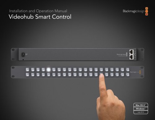
Installation and Operation Manual<br />
Videohub Smart Control<br />
Mac OS X <br />
Windows <br />
July 2012
Contents<br />
Videohub Operation Manual<br />
5<br />
7<br />
12<br />
Planning Your Videohub Installation<br />
Videohub Smart Control 6<br />
Hardware Installation<br />
Connecting Videohub Smart Control with Ethernet 7<br />
Connecting Videohub Smart Control with USB 10<br />
Labelling Control Panels 11<br />
Software Installation<br />
Installing the Videohub Smart Control Software 12<br />
Updating the Software in Your Videohub Smart Control 13<br />
Configuring the Videohub Smart Control Software 14<br />
18<br />
20<br />
21<br />
Using Hardware Control Panels<br />
Help<br />
Using Videohub Smart Control 18<br />
Warranty Information
3<br />
Welcome<br />
Welcome to Videohub Smart Control!<br />
Videohub Smart Control is simple to install. We've extracted the relevant pages from the Videohub manual<br />
so you don't need to read too much. All the information in this mini manual can also be found in the<br />
Videohub manual.<br />
We hope you share our dream for the television industry to become a truly creative industry by allowing<br />
anyone to have access to the highest quality video.<br />
Previously high end television and post production required investment in millions of dollars of hardware,<br />
and professional SDI routing switchers have always been way too high in cost for most people to afford.<br />
HD-SDI is even worse and until now, only the largest post production and television facilities could afford<br />
HD-SDI routing. Videohub changes all that and even enables you to pipe 2K film around your studio just<br />
like video. Now Videohub Smart Control makes it even easier to route video using dedicated, broadcast<br />
quality, hardware <strong>control</strong> panels that are also affordable. We hope you get years of use from it and have lots<br />
of fun connecting everyone in your facility together!<br />
This instruction manual should contain all the information you’ll need on installing your Videohub Smart<br />
Control, although it’s always a good idea to ask a technical assistant for help if you are not sure what IP<br />
addresses are, or if you don’t know much about computer networks. Videohub Smart Control is easy to<br />
install, however, there are a few slightly technical preferences you will need to set after you install it.<br />
We think it should take you approximately 5 minutes to complete installation. Please check our web site at<br />
www.<strong>blackmagic</strong>-design.com and click the support page to download the latest updates to this manual<br />
and Videohub software including the Blackmagic Videohub Smart Control utility. Lastly, please register<br />
your Videohub Smart Control when downloading software updates so we can keep you updated when<br />
new software is released. We are constantly working on new features and improvements, so we would love<br />
to hear from you!<br />
Grant Petty<br />
CEO Blackmagic Design
4<br />
Welcome<br />
How to read as little of this manual as possible<br />
Most people only need to read one or two pages out of each section of this manual and there is no need to<br />
read every page. Here is what you'll learn in each section.<br />
Planning<br />
First, go to the "Planning your Videohub Installation" section for your Videohub Smart Control. This section<br />
provides you with all the information you need to know before buying or installing a Videohub Smart<br />
Control. You can plan how to set it up so there are no nasty surprises.<br />
Hardware Installation<br />
Hardware Installation covers connection of Videohub Smart Control via Ethernet and USB as well as how to<br />
make neat labels and avoid damaging the unit.<br />
Software Installation and Configuration<br />
Now it's time to install and configure the software for your Videohub Smart Control.<br />
Routing Video<br />
Now that the hardware and software is set up, it's time to start routing video!
5<br />
Planning Your Videohub Installation<br />
Videohub Smart Control<br />
USB for connecting<br />
to a Windows or<br />
Mac OS X computer<br />
Cable tie point<br />
Illuminated<br />
buttons for router<br />
source selection<br />
+12 volt power supply<br />
connection. Includes<br />
power supply<br />
Single or multiple<br />
destinations<br />
supported<br />
Button caps can<br />
be removed for<br />
custom labelling<br />
Supports power<br />
over Ethernet<br />
Macro buttons<br />
for simultaneous<br />
routing<br />
Take button<br />
can be enabled<br />
Includes Ethernet<br />
loop through
6<br />
Planning Your Videohub Installation<br />
Planning your Videohub Smart Control Installation<br />
Videohub Smart Control is a rack-mountable <strong>control</strong> panel, with 40 backlit pushbuttons and Ethernet<br />
connectivity, which works with all models of Videohub. It can be configured to work with one or many SDI<br />
destination devices, using the included software utility for Mac OS X and Windows. Once configured for<br />
your SDI equipment and Videohub router, Videohub Smart Control no longer requires a computer and can<br />
immediately change SDI routes as desired.<br />
The front panel of Videohub Smart Control can be removed to allow insertion of labels under the buttons.<br />
All 40 pushbuttons can be variably backlit to ensure the labels can be easily read, even in dark rooms.<br />
When configured for a single SDI destination, such as a monitor or deck, the pushbuttons can instantly<br />
switch between 40 different SDI sources on the same Videohub router. When configured for multiple SDI<br />
destinations, destination buttons become gold colored, source buttons become white, and the lower right<br />
button can be configured as a take button and illuminates red. Macro buttons illuminate green when enabled<br />
and each one can be configured to perform up to 16 simultaneous crosspoint switches. The Blackmagic<br />
Videohub Smart Control configuration utility runs on Mac OS X and Windows computers and uses a USB<br />
2.0 connection to Videohub Smart Control. You will need to provide a USB 2.0 type A to mini B male cable.<br />
This same USB cable can be used for applying occasional firmware updates downloaded from the Blackmagic<br />
Design website. Programmable firmware can provide new features, compatibility with new hardware and<br />
support for new formats. The Blackmagic Videohub Smart Control utility is used to apply firmware updates,<br />
on Mac OS X and Windows computers, and uses a USB 2.0 connection to Videohub Smart Control.<br />
Videohub Smart Control connects to any Videohub via 10/100Base-T Ethernet networking and also includes<br />
a loop through Ethernet port for connecting to additional <strong>control</strong> panels, Videohub routers or other network<br />
devices. You will need to provide a standard RJ45 Ethernet network cable to connect Videohub Smart<br />
Control to your Ethernet network switch.<br />
Videohub Smart Control features power over Ethernet meaning no external power supply is required if<br />
used with a power over Ethernet switch. If your Ethernet switch does not provide power over Ethernet,<br />
use the included universal power supply with international power socket adapters for all countries.<br />
To stop power from being accidentally disconnected, a cable tie point is included just below the power<br />
socket to lock down the power connection. You will need to provide a mains power socket for the universal<br />
power supply.<br />
Videohub Smart Control is 1 rack unit high and less than an inch thick. You will need to leave enough space<br />
in your equipment rack to install the Videohub Smart Control hardware. You can rack-mount Videohub<br />
Smart Control at the front or at the rear of the rack to leave space for other equipment. When configured<br />
for a single SDI destination, install Videohub Smart Control immediately under an SDI deck or monitor you<br />
wish to <strong>control</strong>. If you don’t have a rack, then you can leave it in a safe place on the floor!
7<br />
Hardware Installation<br />
Connecting Videohub Smart Control with Ethernet<br />
Videohub Smart Control connects to any Videohub via standard Ethernet networking and can be powered<br />
over Ethernet or with an external power supply. Videohub Smart Control has two 10/100Base-T Ethernet<br />
ports. The In port usually connects directly to the Ethernet network switch and then to any Videohub router<br />
on your local area IP based network. Alternatively the In port can connect directly to any Ethernet-equipped<br />
Videohub using a standard Ethernet cable and without the need for a network switch. The Out port provides<br />
a loop through Ethernet connection to additional <strong>control</strong> panels, Videohub router or other network devices.<br />
The loop through Ethernet connection is useful if you want to add Videohub Smart Control to your network<br />
without having to run an additional cable back to the network switch.<br />
You will need to carry out the following steps to connect Videohub Smart Control to the local area IP based<br />
network.<br />
Step 1. Videohub Smart Control features power over Ethernet meaning no external power supply is<br />
required if used with a power over Ethernet switch. You can skip this step if your network switch<br />
provides power over Ethernet. Otherwise connect the included power supply to Videohub Smart<br />
Control. No problem will be caused by connecting the power supply and power over Ethernet at<br />
the same time.<br />
Step 2. Use the network In port on Videohub Smart Control to connect to your network switch, or directly<br />
to an Ethernet-equipped Videohub, with a standard RJ45 Ethernet cable.<br />
Step 3. You might also wish to connect another network device to the network Out port on Videohub<br />
Smart Control, such as a Videohub router, another Videohub Smart Control or other network<br />
devices such as a computer or VoIP phone. The Out port does not provide power over Ethernet<br />
and any network device connected to this port will require its own power supply.
8<br />
Hardware Installation<br />
In most facilities, Videohub is usually shared via an Ethernet network switch so it can be <strong>control</strong>led by<br />
computers on the network as well as by Videohub Smart Control. See "Connection method 1".<br />
Videohub Smart Control connected via Ethernet networking Network Switch<br />
Ethernet<br />
Connection method 1. Connecting to an Ethernet-equipped Videohub via a network switch.<br />
Videohubs without a built-in Ethernet port can be connected as shown in "Connection method 2".<br />
Videohub Smart Control connected via Ethernet networking<br />
Connection method 2. Connecting to a USB-attached Videohub via a network switch.<br />
You might wish to connect your Videohub Smart Control directly to an Ethernet-equipped Videohub if:<br />
• you need to set up very fast<br />
• you don't have any requirement to share Videohub on the network so it can be <strong>control</strong>led by computers<br />
on the network<br />
• you don't have much space, such as in an OB van<br />
• you have a limited power budget, such as in an OB van<br />
A regular Ethernet cable can be used between Videohub Smart Control and the Videohub. There is no<br />
need to use a special crossover cable. See "Connection method 3".<br />
Videohub Smart Control connected via Ethernet networking<br />
Ethernet<br />
Ethernet<br />
Connection method 3. Connecting directly to an Ethernet-equipped Videohub.<br />
Videohub Server computer<br />
Videohub connected via Ethernet<br />
Network Switch<br />
Videohub connected via Ethernet<br />
Videohub connected via USB
9<br />
Hardware Installation<br />
When power is first connected to Videohub Smart Control, a self-test will be conducted and all the buttons<br />
will display their test lights in the following sequence: red, green, blue and white.<br />
The top left button of a Smart Control panel indicates its network status, using the following diagnostic<br />
display, as long as the panel is not selected in the Videohub Smart Control software:<br />
Pink flashing light - unit is attempting to acquire an IP address. The button should quickly become<br />
red if the unit is set to use a static IP address, or if the unit successfully acquires an IP address from the<br />
DHCP server. If the button took several minutes before turning red, the unit has failed to acquire an<br />
IP address and has eventually provided itself with a self-assigned AutoIP address in the 169.254.xxx.<br />
xxx format. Unless you wish to use an AutoIP address, disconnect and firmly reconnect the network<br />
cables to ensure they are properly connected, check for faulty network cables and make sure<br />
the DHCP server has spare IP addresses available. Then unplug and reconnect all power sources from<br />
Videohub Smart Control so it will request a new IP address from the DHCP server. The button should quickly<br />
become red.<br />
Red flashing light - unit has acquired an IP address and is attempting to connect to the Videohub Server.<br />
Make sure the Videohub Server is powered on and connected via Ethernet.<br />
Yellow flashing light - unit has connected to a Videohub Server computer but the Videohub Server is<br />
running an incompatible software or firmware version. Update Videohub with the latest version of Videohub<br />
software and firmware and then power cycle Videohub Smart Control.<br />
No flashing light - unit has successfully connected to the Videohub Server and is ready to <strong>control</strong> the<br />
Videohub if solid white, or solid white and gold, lights can be seen.
10<br />
Hardware Installation<br />
Side view of Videohub Smart Control showing the mini-B type<br />
USB port<br />
Connecting Videohub Smart Control with USB<br />
A USB 2.0 connection, to a computer, is used to configure the network and button settings of Videohub<br />
Smart Control.<br />
When viewed from the rear of the unit, the mini-B type USB port can be found on the small, left panel of the<br />
chassis, just in front of the rack-mounting holes.<br />
The USB port will become inaccessible once Videohub Smart Control has been installed in a rack. Therefore<br />
most people will usually configure Videohub Smart Control via USB, and then remove the USB cable, before<br />
installing the unit in a rack.<br />
If you are likely to reconfigure Videohub Smart Control periodically, then it may be more convenient to<br />
permanently connect a USB cable to the unit before installing Videohub Smart Control in a rack. This will<br />
enable Videohub Smart Control to connect to a computer via USB without needing to remove the unit<br />
from the rack.
11<br />
Hardware Installation<br />
Steps 3-5. Remove the 4 screws, lift off the face plate and then<br />
the button caps<br />
Step 7. Lightly press the four corners of the square label into the<br />
rounded corners of the clear cap<br />
Labelling Control Panels<br />
Videohub Smart Control and Smart Videohub have removable face plates which provide access to the<br />
buttons for labelling.<br />
Included with the software installer is a Smart Labels folder containing both PDF and Adobe Illustrator<br />
template files. You can print and use either of these files for labelling the buttons. The Illustrator file contains<br />
text boxes so you can add your text labels before printing them out. If you don’t have Adobe Illustrator, you<br />
can just print out the PDF file and write on the labels. Then cut out the square labels so they are ready to be<br />
inserted in to the buttons.<br />
To remove the face plate:<br />
Step 1. Power off the unit and disconnect all cables.<br />
Step 2. Remove the unit from the rack and lay it flat with the buttons facing upwards and the Ethernet<br />
ports face-downwards on the table.<br />
Step 3. Using a No. 2 Phillip’s head screwdriver, remove the 4 screws found on each of the top and bottom<br />
sides of the faceplate.<br />
Step 4. Now lift the face plate off the rest of the unit.<br />
Step 5. The button caps can be easily lifted off with your fingers. Remove the clear cap from a button that<br />
you wish to label, while taking care to avoid lifting the silicon button membrane.<br />
Step 6. Loosely place the printed label into the upturned clear cap.<br />
Step 7. Use a pointy device, such as the tip of a screwdriver, to lightly press the four corners of the square<br />
paper label into the four, rounded corners of the clear cap. Avoid using a pen for the pointy device<br />
as it is likely to mark your labels.<br />
Step 8. Reinstate the clear cap containing the printed label. As the clear cap is pressed down on to its<br />
silicon button, the paper label will be pushed forward, and neatly held flat against the window of<br />
the clear cap. Repeat for as many buttons as you wish to label.<br />
Step 9. Lower the face plate back into position, making sure the Blackmagic Design logo is the correct<br />
way up.<br />
Step 10. Replace the eight screws.
12<br />
Software Installation<br />
Mac OS X installation: Drag the Blackmagic Videohub Smart<br />
Control utility to the Applications folder<br />
Windows installation: Follow install prompts.<br />
Installing the Videohub Smart Control Software<br />
The Blackmagic Videohub Smart Control software runs on the latest Lion and Mountain Lion versions<br />
of Mac OS X. On the Windows platform, Videohub software runs on both 32 and 64-bit versions of<br />
Windows 7 with the latest service packs installed. Testing on previous versions of these operating systems is<br />
not conducted and so it is always best to keep up to date with the latest versions of Mac OS X and Windows.<br />
The Blackmagic Videohub Smart Control software only needs to be installed on one computer running Mac<br />
OS X or Windows.<br />
While the CD supplied with some models of Videohub contains the software installer, we recommend<br />
you visit www.<strong>blackmagic</strong>-design.com to ensure you have the latest version.<br />
On Mac OS X, open the supplied CD, or downloaded disk image, and drag the Blackmagic Videohub<br />
Smart Control utility to your Applications folder.<br />
The Videohub software installer for Windows also installs the Blackmagic Videohub Smart Control utility and<br />
there is nothing more you need to install. If you have not already installed the latest version of the Videohub<br />
software for Windows, you will need to conduct the following steps.<br />
Locate the installer file and double-click it. This will be on the supplied CD or, if downloaded<br />
from the Blackmagic website, in your downloads folder. A dialog will appear saying, “Found new hardware”<br />
and the Hardware Wizard will start. If prompted to search the Windows Update Website, select, “No, not<br />
at this time” and click “Next”.<br />
Select “Install the Software Automatically” and the system will find the Videohub Smart Control drivers<br />
for you.<br />
A “This software has not passed logo certification” or “The publisher could not be verified“ warning may<br />
reappear during this process. Choose to “Continue Anyway” or “Run“.<br />
Once this is complete and Videohub Smart Control is connected and powered on, you are ready to<br />
configure the device for your facility.
13<br />
Software Installation<br />
Blackmagic Videohub Smart Control application icon<br />
This message will appear if a firmware update is required.<br />
The update will take about 2 minutes to complete.<br />
Updating the Software in Your Videohub Smart Control<br />
Once the software installation has been completed and Smart Control is powered on, it is a good idea to<br />
check that the internal software is up to date.<br />
Step 1. Launch the Blackmagic Videohub Smart Control utility.<br />
Step 2. Connect your Smart Control unit to the computer via USB 2.0.<br />
Step 3. If no software update is required, you will simply see the settings used by your Smart Control.<br />
Settings can be changed now if desired and this is a good opportunity to give each Smart Control<br />
a unique name. Please skip the rest of the steps in this section as your Smart Control is already up<br />
to date.<br />
If a software update is required, the following message will appear: "Software Update Required. The<br />
software on this Smart Control is out of date. Would you like to update it now?" Click Yes. The update will<br />
take about 2 minutes to complete.<br />
Step 4. The message, "Software Update Complete," should appear at completion of the update. Click<br />
OK to dismiss the message. Settings can be changed now if desired and this is a good opportunity<br />
to give each Smart Control a unique name.<br />
Step 5. You can now unplug the USB cable from your Smart Control.
14<br />
Software Installation<br />
Any panels discovered on the network will be listed in the Smart<br />
Control Panels pane with an Ethernet network icon.<br />
Any USB-connected panels will be listed in the Smart Control<br />
Panels pane with a USB icon.<br />
Configuring the Videohub Smart Control Software<br />
After installing the Videohub Smart Control software, launch Blackmagic Videohub Smart Control and<br />
it should immediately search your network for any Smart Control panels. Any panels discovered on the<br />
network will be listed in the Smart Control Panels pane with an Ethernet network icon next to their names. If<br />
several Smart Control panels are listed, but you don't know which one is which, select one of them and then<br />
press the "Identify" button. This will cause all the buttons of the selected Smart Control panel to flash white.<br />
Select the name of the desired Smart Control panel and you will be able to change the Smart Control name<br />
and also the button settings for each Smart Control. Network settings will remain grayed out and can only<br />
be changed via USB.<br />
If no Smart Control panels are found on the network, some units might not have received an IP address via<br />
DHCP and it will be necessary to manually configure each unit with appropriate network settings. To do so,<br />
connect a Smart Control to your computer via a USB 2.0 type A-mini B male cable and launch Blackmagic<br />
Videohub Smart Control. If the utility prompts you to update the software, refer to the previous section<br />
named "Updating the Software in Your Videohub Smart Control". The USB-connected Smart Control will<br />
be automatically selected in the Smart Control Panels pane and will show a USB icon next to its name. You<br />
will be able to change all name, network and button settings for the USB-connected unit. After you have<br />
finished configuring the unit, the USB cable can be removed.<br />
The Videohub Smart Control utility automatically searches your network for any Smart Control panels. One panel has been<br />
found in this picture.
15<br />
Software Installation<br />
Blackmagic Videohub Smart Control network settings<br />
You can manually add a Smart Control, by IP address, to the list of<br />
Smart Control Panels<br />
If a Smart Control panel is selected in the Videohub Smart Control software, all of the panel's buttons will<br />
illuminate with the same colors and intensity as shown in the software interface. While the panel is selected<br />
in the software, the top left button will not indicate the status of the unit.<br />
After configuring the network and button settings in the Blackmagic Videohub Smart Control utility, quit<br />
the software or unplug its USB connection. If the top left button begins to flash, refer to the diagnostic<br />
light information in the previous section named "Connecting Videohub Smart Control with Ethernet."<br />
Otherwise, you can immediately test the buttons as you program them and verify the SDI routes are valid.<br />
Network Settings<br />
Each Videohub Smart Control unit requires an IP address in order to communicate with a Videohub via the<br />
IP-based network.<br />
When configuring Videohub Smart Control via USB, you can choose DHCP or Static IP. DHCP automatically<br />
obtains all the network settings for your Videohub Smart Control and is the easier choice.<br />
If you decide to use a static IP address, please ask your system administrator for a spare IP address to avoid<br />
creating an IP conflict on your network. You will then need to complete the IP address, subnet mask and<br />
gateway details for your Videohub Smart Control hardware. A static IP address must be used if directly<br />
connecting Videohub Smart Control to an Ethernet-equipped Videohub without using a network switch.<br />
You will also need to complete the IP details for the Remote Videohub which you wish to <strong>control</strong> with your<br />
Videohub Smart Control. The remote Videohub is the Videohub Server and could refer to a Videohub<br />
Server computer or an integrated Videohub Server.<br />
Add Smart Control<br />
If you already know the IP address of a Smart Control but it hasn't automatically appeared in the Smart<br />
Control Panels pane, you can add the Smart Control manually. To do so, click Add Smart Control (+) at the<br />
bottom of the Smart Control Panels pane. Type in the IP address of the Smart Control panel and click OK.<br />
The software will verify the presence of the Smart Control unit and add it to the Smart Control Panels list. If<br />
the Blackmagic Videohub Smart Control utility does not find a Smart Control at the specified address, it will<br />
not add the unit to the list and will instead present an error message. You can use Blackmagic Smart Control<br />
Utility to manually add a Smart Control when connected to Smart Control hardware via Ethernet or USB.
16<br />
Software Installation<br />
Blackmagic Videohub Smart Control configured with<br />
multiple destinations.<br />
Click on the desired Source or Destination button<br />
to configure the button.<br />
Enter the number of the Videohub port to which the SDI device<br />
is connected.<br />
Button Settings: Number of Destinations<br />
Videohub Smart Control can be configured as a Cut-Bus <strong>control</strong>ler or as an XY <strong>control</strong>ler.<br />
When configured as a Cut-Bus <strong>control</strong>ler, every button represents an SDI source and there is only one<br />
destination. Use this configuration when dedicating a Videohub Smart Control unit to a single destination<br />
device, such as an SDI monitor or deck. All of the buttons will become white to indicate that they are all<br />
source buttons. Simply slide the “Number of Destinations” slider all the way to the left so the number of<br />
destinations becomes “1”. The “Destination” button below the slider will become active. Click on the active<br />
“Destination” button and enter the number of the Videohub output port, to which the destination device<br />
is connected, in to the “Router SDI Out A” field. If your destination device is receiving dual-link HD-SDI<br />
or dual-stream 3D, you will also need to enter an output port number in to the “Router SDI Out B” field.<br />
There is also a “Router Remote” field if your Videohub is also routing RS-422 deck <strong>control</strong> to the destination<br />
device. Click “OK” to confirm the Destination settings.<br />
When configured as an XY <strong>control</strong>ler, Videohub Smart Control can be configured to work with up to 20<br />
destinations. The source buttons will illuminate white and the destination buttons will illuminate gold-colored.<br />
Use this configuration if you don’t intend to dedicate a Videohub Smart Control unit to each destination<br />
device. Simply slide the “Number of Destinations” slider to the right so the number of destinations increases<br />
to the desired number. The “Destination” button below the slider will become grayed out and inactive. You<br />
can now configure the destination buttons by clicking on each gold button in the software interface. Enter<br />
the number of the Videohub output port, to which the destination device is connected, in to the “Router<br />
SDI Out A” field. If your destination device is receiving dual-link HD-SDI or dual-stream 3D, you will also<br />
need to enter an output port number in to the “Router SDI Out B” field. There is also a “Router Remote”<br />
field if your Videohub is also routing RS-422 deck <strong>control</strong> to the destination device. Click “OK” to confirm<br />
the destination settings. If you increase the number of destination buttons, there will be a corresponding<br />
decrease in the number of available source buttons.<br />
Source buttons are configured in much the same way as destination buttons by clicking on each white<br />
button in the software interface. Enter the number of the Videohub input port, to which the source device is<br />
connected, in to the “Router SDI In A” field. If your destination device is receiving dual-link HD-SDI or dualstream<br />
3D, you will also need to enter an input port number in to the “Router SDI In B” field. There is also<br />
a “Router Remote” field if your Videohub is also routing RS-422 deck <strong>control</strong> from the source device. Click<br />
“OK” to confirm the source settings.
17<br />
Software Installation<br />
Button settings in Blackmagic Videohub Smart Control.<br />
Up to 16 crosspoint routes can be changed by a single macro.<br />
The Take button illuminates red in the lower right corner<br />
Button Settings: Number of Macros<br />
If you want to make multiple crosspoint routing changes simultaneously, you can enable macro buttons so<br />
that a single button press will change up to 16 crosspoint routes. Slide the "Number of Macros" slider to<br />
enable up to 10 macro buttons. As you increase the number of macro buttons, there will be a corresponding<br />
decrease in the number of available source buttons.<br />
Click a green macro button to reveal the corresponding Macro window and then enter up to 16 pairs of<br />
sources and destinations. When finished, click the OK button to save the routes and close the window.<br />
Button Settings: Take Button<br />
When the “Use Take Button” is enabled, the lower right button becomes red-colored. Use this configuration<br />
if you wish to be able to select a change of route and then confirm the change by pressing the red<br />
“Take” button.<br />
The take button can be used with both Cut-Bus and XY <strong>control</strong>ler configurations and can also be used with<br />
macros.<br />
When the take button is enabled, it replaces whatever source, destination or macro button had previously<br />
been configured in the same button location.<br />
Button Settings: Backlight<br />
Adjust the backlight slider to vary the brightness of the backlit buttons as desired.<br />
Enable the “Backlight Destinations Only” button if you wish to disable the backlighting of the white<br />
source buttons.<br />
Load/Save Settings<br />
If you intend to use your Videohub Smart Control as a Cut-Bus <strong>control</strong>ler, and dedicate a number of<br />
Videohub Smart Control units to single destination devices in your facility, it can be convenient to save the<br />
settings from an already configured unit and then load the settings file in to the other units. After loading the<br />
pre-configured settings in to the other units, you need only update network settings and the SDI destination<br />
device for each of the other units. Load/Save settings can also be used with XY <strong>control</strong>ler configurations.<br />
You can load and save settings by choosing “Load Settings” or “Save Settings” from the File menu.
18 Using Hardware Control Panels<br />
Videohub Smart Control configured as a Cut-Bus <strong>control</strong>ler and<br />
with a Take button<br />
Videohub Smart Control configured as an XY <strong>control</strong>ler and with<br />
a Take button<br />
Using Videohub Smart Control<br />
After configuring the Videohub Smart Control hardware with the Blackmagic Videohub Smart Control<br />
software utility, there is nothing more to do other than change video routes as desired.<br />
Using Videohub Smart Control as a Cut-Bus Controller<br />
If Videohub Smart Control has been configured as a Cut-Bus <strong>control</strong>ler, the destination device has already<br />
been chosen and you only need to choose a video source.<br />
• Select one of the white, video source buttons. The video source will immediately be connected and<br />
viewable on the destination device, such as an SDI monitor. The selected source button will be brightly<br />
illuminated compared with the other source buttons making it obvious which source has been chosen.<br />
• If the Take button has been enabled, the current source button will remain lit and both the new source<br />
button and the Take button will begin to flash. The change of route will not take place until you confirm<br />
by pressing the Take button. If you accidentally pushed the wrong source button, simply press the<br />
desired source button before pressing the Take button.<br />
Using Videohub Smart Control as an XY Controller<br />
If Videohub Smart Control has been configured as an XY <strong>control</strong>ler, destination buttons appear gold-colored<br />
and source buttons illuminate white. When working with multiple destinations, always select a destination<br />
button before selecting a source button.<br />
• To change routes, start by selecting a gold destination button and it will illuminate brightly compared<br />
with the other destination buttons. If a video source has previously been connected to this destination,<br />
it’s button will be brightly illuminated white. Now press the desired video source button to connect a<br />
new source to the destination. The video source will immediately be connected and viewable on the<br />
destination device, such as an SDI monitor. The new source button will brightly illuminate white, and<br />
the brightness of the previous source button will reduce to normal. To change another route, select<br />
another destination button and then select a new source button.<br />
• If the Take button has been enabled, the current source button will remain lit and both the new source<br />
button and the Take button will begin to flash. The change of route will not take place until you confirm<br />
by pressing the Take button. If you accidentally pushed the wrong source button, simply press the<br />
desired source button before pressing the Take button.
19 Using Hardware Control Panels<br />
Locking and Unlocking Routes<br />
If you wish to lock a destination using Videohub Smart Control, press and hold the desired destination for<br />
2 seconds until it turns blue and then release it. The corresponding source button will also illuminate. If you<br />
attempt to change sources for a locked destination, the destination button will flash blue because the route<br />
is locked so the source cannot be changed.<br />
To unlock the destination, press and hold the button for two seconds until it returns to the standard gold<br />
color. You cannot unlock destination buttons locked by another computer, iPad or Smart Control, and the<br />
locked destination button will flash blue if you attempt to do so. If you encounter a locked destination, and<br />
do not know who locked the video device, you can override the lock using the Videohub software on a Mac<br />
OS X or Windows computer.<br />
Using Macros<br />
If you press a green macro button, it will simultaneously make the crosspoint changes you have previously<br />
configured in the Videohub Smart Control software. Each button can be configured with up to 16 crosspoint<br />
routes.<br />
If you have the Take button enabled, the simultaneous change of routes will not take place until you confirm<br />
by pressing the Take button.
20<br />
Help<br />
There are four steps to getting help.<br />
Step 1. Check out the Blackmagic Design web site www.<strong>blackmagic</strong>-design.com and click on the<br />
Support page for the latest support information.<br />
Step 2. Call your dealer.<br />
Your dealer will have the latest technical updates from Blackmagic Design and should be able<br />
to give you immediate assistance. We also recommend you check out the support options your<br />
dealer offers as they can arrange various support plans based on your workflow requirements.<br />
Step 3. The next option is to email us with your questions using the web form at<br />
www.<strong>blackmagic</strong>-design.com/support/contact<br />
Step 4. Phone a Blackmagic Design support office. Check our web site for current support phone<br />
numbers in your area. www.<strong>blackmagic</strong>-design.com/company.<br />
Please provide us with as much information as possible regarding your technical problem and system<br />
specifications so that we may try to respond to your problem as quickly as possible.
21<br />
Warranty<br />
Limited Warranty<br />
Blackmagic Design warrants that Videohub routers will be free from defects in materials and workmanship<br />
for a period of 36 months from the date of purchase excluding connectors, cables, cooling fans, fuses,<br />
keyboards and batteries which will be free from defects in materials and workmanship for a period of<br />
12 months from the date of purchase. Blackmagic Design warrants that Videohub Smart Control will be<br />
free from defects in materials and workmanship for a period of 12 months from the date of purchase.<br />
If a product proves to be defective during this warranty period, Blackmagic Design, at its option, either will<br />
repair the defective product without charge for parts and labor, or will provide a replacement in exchange<br />
for the defective product.<br />
In order to obtain service under this warranty, you the Customer, must notify Blackmagic Design of the<br />
defect before the expiration of the warranty period and make suitable arrangements for the performance<br />
of service. The Customer shall be responsible for packaging and shipping the defective product to a<br />
designated service center nominated by Blackmagic Design, with shipping charges pre paid. Customer<br />
shall be responsible for paying all shipping changes, insurance, duties, taxes, and any other charges for<br />
products returned to us for any reason.<br />
This warranty shall not apply to any defect, failure or damage caused by improper use or improper or<br />
inadequate maintenance and care. Blackmagic Design shall not be obligated to furnish service under<br />
this warranty: a) to repair damage resulting from attempts by personnel other than Blackmagic Design<br />
representatives to install, repair or service the product, b) to repair damage resulting from improper<br />
use or connection to incompatible equipment, c) to repair any damage or malfunction caused by the<br />
use of non Blackmagic Design parts or supplies, or d) to service a product that has been modified or<br />
integrated with other products when the effect of such a modification or integration increases the time or<br />
difficulty of servicing the product. THIS WARRANTY IS GIVEN BY BLACKMAGIC DESIGN IN LIEU OF ANY<br />
OTHER WARRANTIES, EXPRESS OR IMPLIED. BLACKMAGIC DESIGN AND ITS VENDORS DISCLAIM<br />
ANY IMPLIED WARRANTIES OF MERCHANTABILITY OR FITNESS FOR A PARTICULAR PURPOSE.<br />
BLACKMAGIC DESIGN’S RESPONSIBILITY TO REPAIR OR REPLACE DEFECTIVE PRODUCTS IS THE<br />
WHOLE AND EXCLUSIVE REMEDY PROVIDED TO THE CUSTOMER FOR ANY INDIRECT, SPECIAL,<br />
INCIDENTAL OR CONSEQUENTIAL DAMAGES IRRESPECTIVE OF WHETHER BLACKMAGIC DESIGN<br />
OR THE VENDOR HAS ADVANCE NOTICE OF THE POSSIBILITY OF SUCH DAMAGES. BLACKMAGIC<br />
DESIGN IS NOT LIABLE FOR ANY ILLEGAL USE OF EQUIPMENT BY CUSTOMER. BLACKMAGIC IS<br />
NOT LIABLE FOR ANY DAMAGES RESULTING FROM USE OF THIS PRODUCT. USER OPERATES THIS<br />
PRODUCT AT OWN RISK.<br />
© Copyright 2012 Blackmagic Design. All rights reserved. ‘Blackmagic Design’, ‘DeckLink’, ‘HDLink’, ‘Workgroup Videohub’, ‘Multibridge Pro’,<br />
‘Multibridge Extreme’, ‘Intensity’ and ‘Leading the creative video revolution’ are registered trademarks in the US and other countries. All other<br />
company and product names may be trade marks of their respective companies with which they are associated.