State of Technology Report for Force Main Rehabilitation, Final ...
State of Technology Report for Force Main Rehabilitation, Final ...
State of Technology Report for Force Main Rehabilitation, Final ...

Create successful ePaper yourself
Turn your PDF publications into a flip-book with our unique Google optimized e-Paper software.
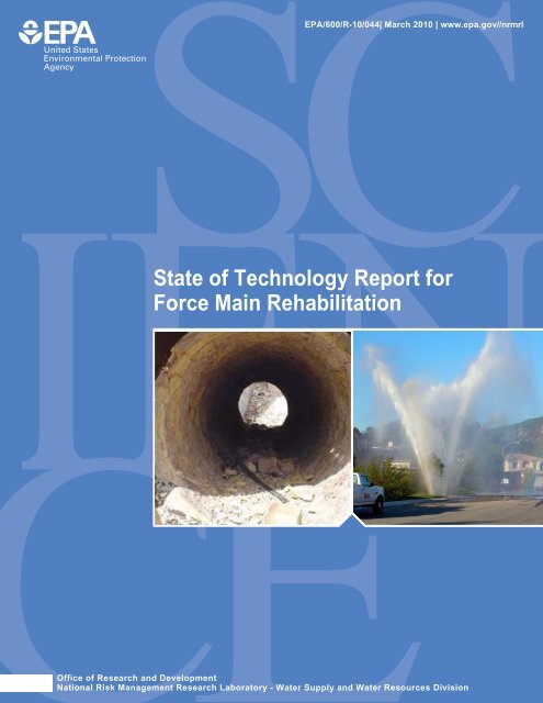
EPA/600/R-10/044| March 2010 | www.epa.gov//nrmrl<br />
<strong>State</strong> <strong>of</strong> <strong>Technology</strong> <strong>Report</strong> <strong>for</strong><br />
<strong>Force</strong> <strong>Main</strong> <strong>Rehabilitation</strong><br />
Office <strong>of</strong> Research and Development<br />
National Risk Management Research Laboratory - Water Supply and Water Resources Division
<strong>Final</strong><br />
<strong>State</strong> <strong>of</strong> <strong>Technology</strong> <strong>Report</strong> <strong>for</strong><br />
<strong>Force</strong> <strong>Main</strong> <strong>Rehabilitation</strong><br />
by<br />
Robert Morrison, P.E.<br />
Tom Sangster<br />
Jason Consultants, LLC<br />
Lili Wang, P.E.<br />
Wendy Condit, P.E.<br />
Battelle Memorial Institute<br />
Contract No. EP-C-05-057<br />
Task Order No. 58<br />
<strong>for</strong><br />
Ariamalar Selvakumar, Ph.D., P.E.<br />
Task Order Manager<br />
U.S. Environmental Protection Agency<br />
National Risk Management Research Laboratory<br />
Water Supply and Water Resources Division<br />
2890 Woodbridge Avenue (MS-104)<br />
Edison, NJ 08837<br />
National Risk Management Research Laboratory<br />
Office <strong>of</strong> Research and Development<br />
U.S. Environmental Protection Agency<br />
Cincinnati, Ohio 45268<br />
EPA/600/R-10/044<br />
March 2010
DISCLAIMER<br />
The work reported in this document was funded by the United <strong>State</strong>s Environmental Protection Agency<br />
(EPA) under Task Order (TO) 58 <strong>of</strong> Contract No. EP-C-05-057 to Battelle Memorial Insititute,<br />
Columbus, OH. The EPA, through its Office <strong>of</strong> Research and Development, funded and managed, or<br />
partially funded and collaborated in, the research described herein. This document has been subjected to<br />
the Agency’s peer and administrative review and has been approved <strong>for</strong> publication. Any opinions<br />
expressed in this report are those <strong>of</strong> the author(s) and do not necessarily reflect the views <strong>of</strong> the Agency,<br />
there<strong>for</strong>e, no <strong>of</strong>ficial endorsement should be inferred. Any mention <strong>of</strong> trade names or commercial<br />
products does not constitute endorsement or recommendation <strong>for</strong> use.<br />
ii
FOREWORD<br />
The U.S. Environmental Protection Agency (EPA) is charged by Congress with protecting the Nation’s<br />
land, air, and water resources. Under a mandate <strong>of</strong> national environmental laws, the Agency strives to<br />
<strong>for</strong>mulate and implement actions leading to a compatible balance between human activities and the ability<br />
<strong>of</strong> natural systems to support and nurture life. To meet this mandate, EPA’s research program is<br />
providing data and technical support <strong>for</strong> solving environmental problems today and building a science<br />
knowledge base necessary to manage our ecological resources wisely, understand how pollutants affect<br />
our health, and prevent or reduce environmental risks in the future.<br />
The National Risk Management Research Laboratory (NRMRL) is the Agency’s center <strong>for</strong> investigation<br />
<strong>of</strong> technological and management approaches <strong>for</strong> preventing and reducing risks from pollution that<br />
threaten human health and the environment. The focus <strong>of</strong> the Laboratory’s research program is on<br />
methods and their cost-effectiveness <strong>for</strong> prevention and control <strong>of</strong> pollution to air, land, water, and subsurface<br />
resources; protection <strong>of</strong> water quality in public water systems; remediation <strong>of</strong> contaminated sites,<br />
sediments and ground water; prevention and control <strong>of</strong> indoor air pollution; and restoration <strong>of</strong> ecosystems.<br />
NRMRL collaborates with both public and private sector partners to foster technologies that<br />
reduce the cost <strong>of</strong> compliance and to anticipate emerging problems. NRMRL’s research provides<br />
solutions to environmental problems by: developing and promoting technologies that protect and improve<br />
the environment; advancing scientific and engineering in<strong>for</strong>mation to support regulatory and policy<br />
decisions; and providing the technical support and in<strong>for</strong>mation transfer to ensure implementation <strong>of</strong><br />
environmental regulations and strategies at the national, state, and community levels.<br />
This publication has been produced as part <strong>of</strong> the Laboratory’s strategic long-term research plan. It is<br />
published and made available by EPA’s Office <strong>of</strong> Research and Development to assist the user<br />
community and to link researchers with their clients.<br />
Sally Gutierrez, Director<br />
National Risk Management Research Laboratory<br />
iii
Introduction<br />
EXECUTIVE SUMMARY<br />
<strong>Force</strong> mains that carry sewage flows under pressure represent a special set <strong>of</strong> challenges <strong>for</strong> sewer<br />
rehabilitation. <strong>Force</strong> mains represent about 7.5% <strong>of</strong> the wastewater system and they typically use<br />
materials that are not commonly used in gravity sewer systems. Ductile iron (DI), cast iron (CI), steel,<br />
and concrete pressure pipe are all material types that are frequently used <strong>for</strong> sewer <strong>for</strong>ce mains, especially<br />
in larger diameters. All <strong>of</strong> these materials are susceptible to both internal corrosion from the sewage flow<br />
(liquid and gaseous states), as well as external corrosion due to the environment in which the pipe is<br />
buried.<br />
Historically, the most common renewal technology employed has been to replace the main using open cut<br />
construction. Part <strong>of</strong> the reason <strong>for</strong> that choice has been a lack <strong>of</strong> rehabilitation technologies appropriate<br />
<strong>for</strong> sewer <strong>for</strong>ce mains. There is a wealth <strong>of</strong> technologies available <strong>for</strong> gravity sewers, but the field has<br />
been limited <strong>for</strong> pressurized systems. Fortunately, that situation is changing as more vendors recognize<br />
the growing opportunity in sewer <strong>for</strong>ce main rehabilitation. The other reason <strong>for</strong> replacement is that<br />
sewer <strong>for</strong>ce mains tend to have a fairly high consequence <strong>of</strong> failure. A rupture <strong>of</strong> a sewer <strong>for</strong>ce main<br />
could release millions <strong>of</strong> gallons <strong>of</strong> raw sewage into the environment posing significant health risks to the<br />
general public. Cleanup costs can be staggering.<br />
As some <strong>of</strong> the newer rehabilitation technologies develop a positive track record <strong>of</strong> use in sewer <strong>for</strong>ce<br />
mains and confidence in their design approach and installation process strengthens, more utilities will be<br />
willing to consider these trenchless technologies as potential renewal solutions. Trenchless methods have<br />
proven themselves to be cost-effective <strong>for</strong> gravity sewer mains, especially when both direct and indirect<br />
costs associated with a replacement program are considered. A similar outcome is expected <strong>for</strong> sewer<br />
<strong>for</strong>ce mains once data on the effectiveness and longevity <strong>of</strong> these technologies and materials and lifecycle<br />
costs become more readily available.<br />
Recognizing that there would be some cross-over amongst the various rehabilitation technologies<br />
common to water mains and gravity sewers, a series <strong>of</strong> technology-specific datasheets were created <strong>for</strong><br />
each identified rehabilitation technology deemed relevant to sewer <strong>for</strong>ce mains and are included as<br />
Appendix A <strong>of</strong> this report. An ef<strong>for</strong>t was made to collect representative cost in<strong>for</strong>mation, but <strong>of</strong>ten only<br />
limited cost data were available.<br />
Characteristics <strong>of</strong> <strong>Force</strong> <strong>Main</strong>s<br />
The approximate length <strong>of</strong> the <strong>for</strong>ce main system in the US is 60,000 miles (96561 km). The Water<br />
Environment Research Foundation (WERF) recently published a report titled “Guidelines <strong>for</strong> the<br />
Inspection <strong>of</strong> <strong>Force</strong> <strong>Main</strong>s” (WERF, 2009). The data from this WERF survey are presented and<br />
characterize the types <strong>of</strong> pipe materials used, diameter ranges, ages, location accessibility, and failure<br />
modes and mechanisms <strong>for</strong> <strong>for</strong>ce mains. Ferrous pipe materials (i.e., CI, DI, and steel) represent on<br />
average 63.4% <strong>of</strong> all pipes used <strong>for</strong> <strong>for</strong>ce mains. Over 91% <strong>of</strong> sewer <strong>for</strong>ce mains are between 4 and 36<br />
inches (100 and 900 mm) in diameter, which are within the non-man entry size range and only 2% are<br />
beyond 50 years in age. Over 91% <strong>of</strong> the <strong>for</strong>ce main pipes are buried. Only 5% <strong>of</strong> the total number <strong>of</strong><br />
<strong>for</strong>ce mains surveyed <strong>for</strong> the WERF project had some built-in redundancy.<br />
Internal corrosion was rated as being responsible <strong>for</strong> ferrous <strong>for</strong>ce main failures 26.2% <strong>of</strong> the time, ahead<br />
<strong>of</strong> all other known causes. External corrosion at 19.2% and third-party damage at 19.4% are the next<br />
most common causes <strong>of</strong> failures in ferrous mains. The most common single cause <strong>of</strong> failure in non-<br />
iv
ferrous <strong>for</strong>ce mains is third-party damage, which accounts <strong>for</strong> 37% <strong>of</strong> failures. Corrosion and structural<br />
failure together account <strong>for</strong> 54% <strong>of</strong> failures.<br />
Renewal Technologies<br />
Renewal <strong>of</strong> <strong>for</strong>ce mains includes repair, rehabilitation, and replacement. The estimate <strong>of</strong> renewal works<br />
in <strong>for</strong>ce mains are between 250,000 and 600,000 linear feet (76,220 and 182,927 meters) or 0.08% to<br />
0.19% <strong>of</strong> the total length on an annual basis. Replacement comprises between 200,000 and 500,000<br />
linear feet (60,976 and 152,439 meters) <strong>of</strong> <strong>for</strong>ce mains annually or some 0.1% to 0.15% <strong>of</strong> the total<br />
length. The best estimate is that between 50,000 and 100,000 linear feet (15,244 and 30,488 meters) <strong>of</strong><br />
<strong>for</strong>ce mains in the US are rehabilitated annually. This represents some 0.02% to 0.03% <strong>of</strong> the overall<br />
length. There are a variety <strong>of</strong> reasons <strong>for</strong> this lower rate <strong>of</strong> rehabilitation in sewer <strong>for</strong>ce mains. The first<br />
is the lack <strong>of</strong> consistently reliable and cost-effective sewer <strong>for</strong>ce main inspection methods and the second<br />
is the low number <strong>of</strong> rehabilitation technologies specific to <strong>for</strong>ce mains.<br />
<strong>Force</strong> mains can operate with a wide range in pressures, from a few feet <strong>of</strong> head to hundreds, so there is<br />
potentially a large number <strong>of</strong> technologies that can be adapted to <strong>for</strong>ce mains from other applications.<br />
Vendors are constantly making improvements to their products so they should always be consulted be<strong>for</strong>e<br />
using any <strong>of</strong> the identified technologies.<br />
Repair<br />
Repair <strong>of</strong> a failure or a deteriorated section <strong>of</strong> pipe is generally focused on only taking remedial action<br />
with one or two sections <strong>of</strong> pipe. Oftentimes this work is done under emergency conditions. The first<br />
objective is to prevent any further spill or damage to the environment and the second objective is to<br />
restore service as quickly as possible. Repair can be broken down into open cut replacement <strong>of</strong> a<br />
section(s) <strong>of</strong> pipe, spot repairs using cured-in-place-pipe (CIPP), mechanical sleeves or repair clamps, or<br />
joint repairs using internal sleeves or external devices. Some examples <strong>of</strong> each are given in this report,<br />
but repair is not a focus <strong>of</strong> this report.<br />
<strong>Rehabilitation</strong><br />
In rehabilitation, the existing pipe becomes part <strong>of</strong> the renewal work. <strong>Rehabilitation</strong> methods will include<br />
the use <strong>of</strong> spray-on linings, close-fit linings, CIPP, and woven hose lining systems. Technologies <strong>for</strong><br />
each <strong>of</strong> these rehabilitation categories are discussed in this report in addition to cleaning requirements<br />
prior to rehabilitation. Because only limited rehabilitation work has been undertaken to date on sewer<br />
<strong>for</strong>ce mains, many <strong>of</strong> the systems available were originally developed <strong>for</strong> water main rehabilitation, but<br />
can be adapted to sewer <strong>for</strong>ce mains.<br />
Spray-on linings have been one <strong>of</strong> the easiest methods <strong>of</strong> rehabilitating a pressurized main when the<br />
primary objective is just to provide corrosion protection to the interior surface. Spray-on linings include<br />
cementitious and polymer materials. Two polymers, epoxy and polyurethane, are used extensively in the<br />
UK water industry to line water mains. Rapid cure time over cement mortar and resistance to s<strong>of</strong>t water<br />
have favored these materials. A new family <strong>of</strong> polymer spray-on linings, based on the use <strong>of</strong> polyurea, is<br />
finding rapid acceptance <strong>for</strong> lining manholes, wetwells, and other structures exposed to corrosive<br />
environments including pipes. One <strong>of</strong> the benefits <strong>of</strong> the use <strong>of</strong> polyurea is a very fast cure, with gel<br />
times in 5 to 40 seconds. The liner can also be spray applied with a thickness up to 2 inches (50 mm).<br />
This liner has the ability to serve as a semi-structural or structural liner and not just provide corrosion<br />
protection.<br />
v
The use <strong>of</strong> close-fit liners is <strong>of</strong>ten called modified sliplining. It involves the use <strong>of</strong> a thin walled liner<br />
with an outside diameter that is similar to the inside diameter <strong>of</strong> the host pipe. The key to installing the<br />
liner is to temporarily reduce the liner diameter to facilitate its insertion into the host pipe. Once the liner<br />
is in place, it is reverted back to its original outside diameter <strong>for</strong>ming a close fit to the host pipe. The two<br />
methods <strong>of</strong> temporarily reducing the diameter <strong>of</strong> the liner is symmetrical or fold-and-<strong>for</strong>m. Polyethylene<br />
(PE) pipe is used <strong>for</strong> the symmetrical reduction process, and both PE and polyvinyl chloride (PVC) <strong>for</strong><br />
fold-and-<strong>for</strong>m.<br />
CIPP is by far the leading method <strong>for</strong> the rehabilitation <strong>of</strong> gravity sewers. With the expiration <strong>of</strong> the<br />
original patent on CIPP, many new variants have been introduced. The main differences are based on<br />
tube construction, method <strong>of</strong> installation, curing method, and type <strong>of</strong> resin.<br />
Woven hose linings differ from ordinary CIPP products by the construction <strong>of</strong> the tube rein<strong>for</strong>cement.<br />
Rather than being made <strong>of</strong> a felt-type material, hose liners are made from either polyester, glass, or<br />
aramid fibers that are woven into a hose-type configuration, similar to the type <strong>of</strong> construction used <strong>for</strong><br />
fire hoses. Three types <strong>of</strong> woven hose lining systems are discussed including adhesive-backed linings,<br />
non-adhesive backed linings, and glass-rein<strong>for</strong>ced thermoplastic linings.<br />
Replacement<br />
Replacement involves the installation <strong>of</strong> a new fully structural pipe to take over the functions <strong>of</strong> the<br />
deteriorated <strong>for</strong>ce main. Several technologies are available <strong>for</strong> online and <strong>of</strong>fline replacement.<br />
Historically, the most common method has been <strong>of</strong>fline replacement by open cut, as the work can be<br />
undertaken with the existing main in operation and it results in a brand new pipe with a known design<br />
life.<br />
The second most common method <strong>of</strong> replacement has been sliplining. Sliplining involves the insertion <strong>of</strong><br />
a new pipe with a smaller outside diameter than the inside diameter <strong>of</strong> the pipe to be rehabilitated. Pipe<br />
lengths can be fused together to create a long continuous string, frequently done with PE and Fusible<br />
PVC, which is then pulled into the host pipe. Alternatively, especially when site conditions prevent<br />
pre-joining long strings <strong>of</strong> pipe, discrete pipe sections can be jointed one at a time and pushed into the<br />
host pipe. PVC, DI, and fiberglass rein<strong>for</strong>ced plastic/glass rein<strong>for</strong>ced plastic (FRP/GRP) pipes are<br />
typically sliplined in this fashion. Mechanically restrained joints can also be employed with these<br />
materials, which would allow pulling <strong>of</strong> the pipe into place.<br />
Pipe bursting involves the breaking up <strong>of</strong> the old pipe and pushing it into the surrounding soil by passing<br />
a bursting or splitting device through it, while pulling a replacement pipe in behind the bursting head.<br />
The replacement pipe is usually high density polyethylene (HDPE), PVC, or DI. In some cases, the<br />
process can be used to expand the void created thus upsizing with the insertion <strong>of</strong> a larger diameter. Pipe<br />
bursting has now been accomplished in diameters from 4 to 60 inches (100 to 1,500 mm). The three basic<br />
bursting methods include static, hydraulic, and pneumatic bursting.<br />
Offline replacement simply involves the installation <strong>of</strong> a new pipe without regard to the line and grade <strong>of</strong><br />
the existing pipe. Normally, the existing deteriorated pipe being replaced is kept in service (at reduced<br />
operating conditions if necessary), while the new replacement pipe is being installed. Typically, methods<br />
<strong>of</strong> <strong>of</strong>fline replacement include open cut excavation and newer trenchless methods such as directional<br />
drilling and microtunneling/pipe jacking. For microtunneling, FRP/GRP, polymer concrete, and steel<br />
pipes can be used.<br />
vi
<strong>Technology</strong> Selection Criteria<br />
Aside from selecting renewal technologies on the basis <strong>of</strong> their fit to the <strong>for</strong>ce main’s operating conditions<br />
(e.g., pressure, burial depth, etc.), other site-specific parameters must be considered in the selection<br />
process. The life-cycle cost <strong>of</strong> the renewal method and its impact on extending the life <strong>of</strong> the asset are<br />
<strong>of</strong>ten the primary concerns in technology selection. As discussed in this report, studies in the US and UK<br />
have shown the relative cost benefits <strong>of</strong> rehabilitation versus open cut replacement in urban environments.<br />
Other site-specific factors that should be taken into consideration include post-renewal capacity needs,<br />
accessibility, future operations and maintenance (O&M) requirements, the condition <strong>of</strong> the host pipe, and<br />
the consequence <strong>of</strong> its failure (criticality).<br />
All rehabilitation options will result in a reduced cross-sectional area. Spray-on linings and close-fit<br />
liners will least impact flow capacity, while sliplining will have the greatest impact. Loss <strong>of</strong> capacity is<br />
mitigated somewhat by improved friction factors. If capacity restraints exist, then replacement may be<br />
the only feasible option.<br />
Other items that can impact the selection <strong>of</strong> a renewal method are accessibility <strong>of</strong> the <strong>for</strong>ce main,<br />
maintenance crews familiarity with the liner system and repair methods, and the criticality <strong>of</strong> the <strong>for</strong>ce<br />
main. The higher the consequences associated with a failure, the more conservative the approach will be<br />
towards renewal <strong>of</strong> the main. A partially deteriorated <strong>for</strong>ce main that has an extremely high consequence<br />
<strong>of</strong> failure would be one that would probably be treated as fully deteriorated from the perspective <strong>of</strong> the<br />
design <strong>of</strong> the rehabilitation system.<br />
Design and Quality Assurance/Quality Control<br />
The design <strong>of</strong> a rehabilitation product to renew the life <strong>of</strong> a distressed sewer <strong>for</strong>ce main ranges from an<br />
inner corrosion barrier to an outright structural replacement. The factors that will control the design are<br />
the condition <strong>of</strong> the existing main, including its expected remaining life if further deterioration is arrested,<br />
and the operating conditions under which that main is used. The degree <strong>of</strong> deterioration is typically<br />
broken down into one <strong>of</strong> two categories: (1) partially deteriorated, where the existing pipe is expected to<br />
support all external loads (soil, live, surcharge), or (2) fully deteriorated where the existing pipe is not<br />
structurally sound.<br />
Design methods currently employed are <strong>for</strong> either interactive or independent liners and depend upon the<br />
condition <strong>of</strong> the existing (host) pipe. Interactive liners are generally thin liners, in direct contact with the<br />
inside wall <strong>of</strong> the existing pipe, with a lower ring tensile stiffness than the existing pipe. Interactive liners<br />
should not be used in sewer <strong>for</strong>ce mains where the existing pipe has deteriorated to a point where it is not<br />
expected to be able to carry the full internal pressure over the renewal design life. An independent liner is<br />
one that is designed to carry the full internal working pressure and surge pressure itself independent <strong>of</strong><br />
any contribution from the host pipe.<br />
Few rehabilitation products are designed specifically <strong>for</strong> use in a sewer <strong>for</strong>ce main. There<strong>for</strong>e, design and<br />
Quality Assurance/Quality Control (QA/QC) requirements and best practices may need to be adapted<br />
from relevant American Water Works Association (AWWA) and American Society <strong>for</strong> Testing and<br />
Materials (ASTM) standards.<br />
The AWWA M28 Manual on <strong>Rehabilitation</strong> <strong>of</strong> Water <strong>Main</strong>s has established four classes <strong>of</strong> design: nonstructural<br />
(Class I), semi-structural (Class II and III), and fully structural (Class IV). Class I liners only<br />
act as corrosion barriers, Class II/III liners are designed to bridge over small holes or gaps in the host<br />
pipe, while Class IV liners will carry the full internal pressure without support from the host pipe.<br />
vii
A whole host <strong>of</strong> ASTM specifications and AWWA standards cover the various types <strong>of</strong> materials and<br />
installation practices that may be used in a renewal project. Many <strong>of</strong> these are included in this report,<br />
along with a brief description. Some <strong>of</strong> the ASTM standards include non-mandatory design appendices,<br />
which are all patterned after Appendix X1 <strong>of</strong> ASTM F1216. ASTM F1216 is the standard practice <strong>for</strong> the<br />
rehabilitation <strong>of</strong> gravity and/or pressure pipes using a CIPP inversion product.<br />
For gravity applications, the design appendix in ASTM F1216 requires that the liner be designed to<br />
support (without buckling) any external hydrostatic head if the host pipe is partially deteriorated and all<br />
external loads (without buckling) if fully deteriorated. Of course, the determination <strong>of</strong> whether the host<br />
pipe is partially or fully deteriorated is subjective. Likewise, depending on the ratio <strong>of</strong> the diameter <strong>of</strong><br />
any holes in the pipe to the pipe diameter, the liner is designed to either act as a flat plate with fixed edges<br />
covering the hole or, if the host pipe is fully deteriorated, then as a thin ring under hoop stress from the<br />
internal pressure. In both <strong>of</strong> these design cases, either the long-term flexural strength or the long-term<br />
tensile strength is used. However, there is no standardized test method defined to determine either <strong>of</strong><br />
these properties <strong>for</strong> a CIPP product. It is up to each manufacturer to establish those long-term properties.<br />
Based on a survey <strong>of</strong> CIPP producers, few if any have embarked on an extensive test program similar to<br />
that required <strong>for</strong> the pressure design <strong>of</strong> FRP/GRP or thermoplastic pipes.<br />
Most <strong>of</strong> the QC requirements in the ASTM and AWWA standards pertain to use in a gravity sewer or a<br />
pressure water main. None combine the corrosion resistance necessitated by the sewer effluent and the<br />
long-term tensile strength <strong>of</strong> a pressurized main. Post-installation closed circuit television (CCTV) is the<br />
most common QC requirement <strong>for</strong> all liners followed by the retrieval <strong>of</strong> samples <strong>for</strong> physical property<br />
verification. Leak tightness testing is also recommended.<br />
Operation and <strong>Main</strong>tenance<br />
Some <strong>of</strong> the best practices <strong>for</strong> O&M are cleaning, addition <strong>of</strong> cathodic protection, installation <strong>of</strong><br />
continuous corrosion monitoring, pressure monitoring, leak monitoring, and acoustic monitoring <strong>of</strong><br />
prestressed concrete cylinder pipe (PCCP) <strong>for</strong> wire breaks. These measures can be effective in either<br />
prolonging the life <strong>of</strong> a buried sewer <strong>for</strong>ce main or allowing a utility to monitor real-time per<strong>for</strong>mance so<br />
action can be taken as needed to repair, rehabilitate, or replace be<strong>for</strong>e a catastrophic failure occurs.<br />
Proper cleaning can improve the capacity and hydraulic per<strong>for</strong>mance <strong>of</strong> a sewer <strong>for</strong>ce main. Cathodic<br />
protection can arrest any further external electrochemical-induced corrosion <strong>of</strong> ferrous mains.<br />
Continuous corrosion monitoring can be installed on new mains or added to existing mains. Ultrasonic<br />
sensors measure loss <strong>of</strong> internal wall thickness. Leaks can be a precursor <strong>of</strong> failure and locating leaks in a<br />
<strong>for</strong>ce main using acoustic devices can help to prevent catastrophic failures.<br />
A rehabilitated main effectively adds to the range <strong>of</strong> material that must be potentially repaired in an<br />
emergency. There are no set procedures <strong>for</strong> repair <strong>of</strong> rehabilitated (i.e., lined) <strong>for</strong>ce mains. This is an<br />
area <strong>of</strong> concern <strong>for</strong> utilities and certainly makes them reluctant to line their mains because they do not<br />
know how to deal with them when emergency repair becomes necessary.<br />
Gaps Between Needs and Available Technologies<br />
Little data are obtained on <strong>for</strong>ce main condition upon which assessment and subsequent rehabilitation<br />
decisions can be based. So rehabilitation decision-making is <strong>of</strong>ten based on operational indicators such as<br />
power consumption, air release valve operation, or main breaks. The renewal decision should be based<br />
on three elements: the rate <strong>of</strong> deterioration <strong>of</strong> assets; the condition <strong>of</strong> critical locations; and whether<br />
spending can be deferred. A first step is to establish risk-based assessment methods to identify <strong>for</strong>ce<br />
mains with serious consequences <strong>of</strong> failure, either in operational or environmental and public impact<br />
viii
terms, or both. A second step is to consider prioritization <strong>for</strong> external data collection. A method <strong>for</strong><br />
identifying high risk locations in terms <strong>of</strong> likelihood <strong>of</strong> failure based on environment and operating<br />
characteristics could pinpoint high risk locations, which would be selected <strong>for</strong> direct inspection.<br />
There is a clear need <strong>for</strong> assessment methodologies that can work with limited data. These could<br />
potentially be based on Bayesian belief networks. There is also a need <strong>for</strong> inspection technologies that<br />
can provide data more cost-effectively to support these assessment methodologies.<br />
A gap exists in terms <strong>of</strong> a design procedure <strong>for</strong> CIPP in pressure applications to ensure that long-term<br />
per<strong>for</strong>mance requirements can be met. Little data are available on the long-term per<strong>for</strong>mance <strong>of</strong><br />
rehabilitation solutions in real environments, which a designer can use to predict the remaining life <strong>of</strong> an<br />
asset that incorporates one <strong>of</strong> these rehabilitation methods. Another capability gap is the access needed to<br />
the main and the need to shut down, dewater, and clean the main <strong>for</strong> rehabilitation. This is an inevitable<br />
feature <strong>of</strong> any internal rehabilitation technology, as it is <strong>for</strong> inspection technologies. This also places a<br />
limitation on the use <strong>of</strong> rehabilitation in <strong>for</strong>ce mains.<br />
Findings and Recommendations<br />
Most <strong>of</strong> the renewal activity has been outright replacement <strong>of</strong> the <strong>for</strong>ce main either by open cut or<br />
trenchless means. New products and technologies are now emerging <strong>for</strong> carrying out a direct condition<br />
assessment on a buried <strong>for</strong>ce main, as well as rehabilitation methods <strong>for</strong> those found in distress.<br />
One method <strong>of</strong> assisting owners in their ef<strong>for</strong>ts to apply some <strong>of</strong> these emerging technologies will be in<br />
the publication <strong>of</strong> demonstration projects and case studies. Also, setting up a decision support system that<br />
helps a utility ask the right questions so that a viable rehabilitation solution emerges is paramount.<br />
It is clear that a system rehabilitation program needs to integrate several aspects and to have a broader<br />
vision than merely the rehabilitation technology and its implementation. The elements that need to be<br />
integrated within the scope <strong>of</strong> an asset management approach include inspection, assessment,<br />
maintenance, and rehabilitation.<br />
Key elements <strong>of</strong> <strong>for</strong>ce main maintenance are regular cleaning, maintenance <strong>of</strong> cathodic protection<br />
systems, and maintenance <strong>of</strong> air release valves. Inclusion <strong>of</strong> corrosion monitoring, pressure monitoring,<br />
and leak monitoring should be considered.<br />
The decision-making process relies on data from inspection to assess risk levels and to decide on<br />
necessary actions. Determining the level <strong>of</strong> data or in<strong>for</strong>mation required to support effective decisions is<br />
a key aspect <strong>of</strong> the process. Too little data and the wrong decisions may be made; too much data and the<br />
cost <strong>of</strong> obtaining the data may exceed its value in the process. Neither scenario is cost-effective. One <strong>of</strong><br />
the key data elements needed is verification <strong>of</strong> the long-term per<strong>for</strong>mance <strong>of</strong> pressure rehabilitation<br />
systems. This should be a major objective <strong>of</strong> the demonstration project.<br />
ix
CONTENTS<br />
DISCLAIMER ..............................................................................................................................................ii<br />
FOREWORD ...............................................................................................................................................iii<br />
EXECUTIVE SUMMARY ......................................................................................................................... iv<br />
FIGURES....................................................................................................................................................xii<br />
TABLES ....................................................................................................................................................xiii<br />
DEFINITIONS........................................................................................................................................... xiv<br />
ACRONYMS AND ABBREVIATION .................................................................................................... xvi<br />
1.0 INTRODUCTION ................................................................................................................................. 1<br />
1.1 Project Background ................................................................................................................... 1<br />
1.2 Project Objectives...................................................................................................................... 2<br />
1.3 Project Approach....................................................................................................................... 3<br />
1.4 Organization <strong>of</strong> <strong>Report</strong>.............................................................................................................. 3<br />
2.0 CHARACTERISTICS OF FORCE MAIN SYSTEMS......................................................................... 5<br />
2.1 Material Usage .......................................................................................................................... 5<br />
2.2 Diameter Distribution................................................................................................................ 5<br />
2.3 Age <strong>of</strong> System ........................................................................................................................... 7<br />
2.4 <strong>Force</strong> <strong>Main</strong> Location ................................................................................................................. 7<br />
2.5 Redundancy............................................................................................................................... 9<br />
2.6 Cause <strong>of</strong> Failure in <strong>Force</strong> <strong>Main</strong>s ............................................................................................... 9<br />
2.6.1 Ferrous <strong>Force</strong> <strong>Main</strong>s..................................................................................................... 9<br />
2.6.2 Non-Ferrous <strong>Force</strong> <strong>Main</strong>s ............................................................................................ 9<br />
3.0: RENEWAL PRACTICES AND TECHNOLOGIES ......................................................................... 11<br />
3.1 Current Utility Practices and Market....................................................................................... 11<br />
3.2 Overview <strong>of</strong> Renewal Technologies ....................................................................................... 12<br />
3.3 Repair ...................................................................................................................................... 14<br />
3.3.1 Open Cut Emergency Replacement............................................................................ 14<br />
3.3.2 Spot Repair – Trenchless............................................................................................ 14<br />
3.3.2.1 Cured-in-Place Pipe ................................................................................... 14<br />
3.3.2.2 Sleeve......................................................................................................... 15<br />
3.3.2.3 External Repair Clamps ............................................................................. 15<br />
3.3.3 Joint Repair ................................................................................................................ 16<br />
3.3.3.1 Internal Joint Repair................................................................................... 16<br />
3.3.3.2 External Joint Repair.................................................................................. 16<br />
3.4 <strong>Rehabilitation</strong> .......................................................................................................................... 17<br />
3.4.1 Cleaning Requirements .............................................................................................. 17<br />
3.4.2 Spray-on Linings ........................................................................................................ 18<br />
3.4.2.1 Cement Mortar Linings.............................................................................. 18<br />
3.4.2.2 Rein<strong>for</strong>ced Mortar Linings......................................................................... 19<br />
3.4.2.3 Epoxy Spray-on Linings ............................................................................ 19<br />
3.4.2.4 Polyurethane Spray-on Linings.................................................................. 20<br />
3.4.2.5 Polyurea Spray-On Linings........................................................................ 21<br />
3.4.3 Close Fit Lining Systems ........................................................................................... 22<br />
3.4.3.1 Symmetrical Reduction Close Fit Lining – PE.......................................... 24<br />
3.4.3.2 Fold-and-Form Close Fit Lining – PE ....................................................... 26<br />
3.4.3.3 Fold-and-Form Close Fit Lining – PVC (Alloy)........................................ 28<br />
3.4.4 Cured-In-Place Pipe ................................................................................................... 30<br />
x
3.4.4.1 Non-Structural to Semi-Structural CIPP Liners......................................... 31<br />
3.4.4.2 Semi-Structural CIPP Liners...................................................................... 32<br />
3.4.4.3 Structural CIPP Liners ............................................................................... 32<br />
3.4.5 Woven Hose Lining System....................................................................................... 35<br />
3.4.5.1 Adhesive-Backed Woven Hose Lining...................................................... 36<br />
3.4.5.2 Non-Adhesive Backed Woven Hose Lining.............................................. 37<br />
3.4.5.3 Glass-Rein<strong>for</strong>ced Thermoplastic Liner...................................................... 38<br />
3.5 Replacement ............................................................................................................................ 39<br />
3.5.1 Online Replacement ................................................................................................... 40<br />
3.5.1.1 Sliplining.................................................................................................... 40<br />
3.5.1.2 Pipe Bursting.............................................................................................. 42<br />
3.5.1.3 Pipe Slitting................................................................................................ 44<br />
3.5.2 Offline Replacement................................................................................................... 44<br />
3.5.2.1 Open Cut .................................................................................................... 44<br />
3.5.2.2 Directional Drilling.................................................................................... 44<br />
3.5.2.3 Microtunneling/Pipe Jacking ..................................................................... 44<br />
4.0: TECHNOLOGY SELECTION CONSIDERATIONS....................................................................... 46<br />
4.1 Life-Cycle Costs...................................................................................................................... 46<br />
4.2 Capacity................................................................................................................................... 48<br />
4.3 Accessibility ............................................................................................................................ 48<br />
4.4 <strong>Main</strong>tenance ............................................................................................................................ 49<br />
4.5 Condition Assessment and Asset Criticality ........................................................................... 49<br />
5.0: DESIGN AND QA/QC....................................................................................................................... 52<br />
5.1 System Design......................................................................................................................... 52<br />
5.1.1 Redundancy in System Design................................................................................... 52<br />
5.1.2 Pig Launchers/Retrieval <strong>for</strong> Cleaning and Inspection................................................ 52<br />
5.2 Renewal Design....................................................................................................................... 53<br />
5.2.1 Degrees <strong>of</strong> Deterioration ............................................................................................ 53<br />
5.2.2 Interactive vs. Independent......................................................................................... 54<br />
5.2.3 Design Loads.............................................................................................................. 54<br />
5.2.4 Other Considerations.................................................................................................. 56<br />
5.3 Product/Material Standards ..................................................................................................... 56<br />
5.4 Design Standards..................................................................................................................... 59<br />
5.4.1 Design <strong>of</strong> Pressure Systems ....................................................................................... 61<br />
5.4.1.1 Partially Deteriorated Case ........................................................................ 61<br />
5.4.1.2 Fully Deteriorated Case ............................................................................. 63<br />
5.5 Installation Standards .............................................................................................................. 64<br />
5.6 QA/QC Requirements ............................................................................................................. 67<br />
5.6.1 Short-Term – Factory and Field Requirements.......................................................... 67<br />
5.6.1.1 PVC Short-Term QA/QC Requirements.................................................... 67<br />
5.6.1.2 PE Short-Term QA/QC Requirements....................................................... 68<br />
5.6.1.3 CIPP Short-Term QA/QC Requirements................................................... 68<br />
5.6.2 Long-Term – Qualification Requirements ................................................................. 69<br />
5.6.2.1 PVC Long-Term QA/QC Requirements.................................................... 69<br />
5.6.2.2 PE Long-Term QA/QC Requirements....................................................... 69<br />
5.6.2.3 CIPP Long-Term QA/QC Requirements ................................................... 70<br />
xi
6.0: OPERATION AND MAINTENANCE.............................................................................................. 71<br />
6.1 Procedures to Prolong the Life <strong>of</strong> Existing <strong>Force</strong> <strong>Main</strong>s ........................................................ 71<br />
6.1.1 Cleaning ..................................................................................................................... 71<br />
6.1.2 Cathodic Protection .................................................................................................... 73<br />
6.1.3 Continuous Corrosion Monitoring ............................................................................. 74<br />
6.1.4 Pressure Monitoring ................................................................................................... 75<br />
6.1.5 Leak Monitoring......................................................................................................... 76<br />
6.1.6 Acoustic Monitoring <strong>for</strong> Wire Breaks in PCCP......................................................... 76<br />
6.2 <strong>Main</strong>tenance and Emergency Repair <strong>of</strong> <strong>Rehabilitation</strong> Systems............................................. 77<br />
7.0: GAPS BETWEEN NEEDS AND AVAILABLE TECHNOLOGIES................................................ 78<br />
7.1 Data Gaps ................................................................................................................................ 78<br />
7.2 Capability Gaps ....................................................................................................................... 79<br />
7.3 Benefits, Costs and Challenges in Closing Gaps..................................................................... 79<br />
8.0: FINDINGS AND RECOMMENDATIONS....................................................................................... 81<br />
8.1 What Systems Would Benefit Most from Being Demonstrated in Field Settings?................. 81<br />
8.2 Key Parameters <strong>for</strong> Evaluation in Demonstration Projects..................................................... 81<br />
8.3 Guidance <strong>for</strong> Establishing a Comprehensive System <strong>Rehabilitation</strong> Program ....................... 83<br />
8.4 Guidance <strong>for</strong> <strong>Main</strong>tenance Programs ...................................................................................... 83<br />
8.5 Sound, Risk-Based, Decision-Making Process Development................................................. 84<br />
8.6 Cost-Effectiveness <strong>of</strong> Decision-Making Processes ................................................................. 84<br />
8.7 Timing <strong>for</strong> <strong>Rehabilitation</strong> Action ............................................................................................ 84<br />
8.8 Demonstration/Verification <strong>of</strong> Pressure System <strong>Rehabilitation</strong>.............................................. 85<br />
9.0: REFERENCES ................................................................................................................................... 86<br />
FIGURES<br />
Figure 2-1. Pipe Material Usage <strong>for</strong> Sewer <strong>Force</strong> <strong>Main</strong>s ......................................................................... 5<br />
Figure 2-2. Diameter Distribution <strong>of</strong> Sewer <strong>Force</strong> <strong>Main</strong>s ........................................................................ 6<br />
Figure 2-3. Age <strong>of</strong> <strong>Force</strong> <strong>Main</strong>s................................................................................................................ 7<br />
Figure 2-4. Location <strong>of</strong> <strong>Force</strong> <strong>Main</strong>s ........................................................................................................ 8<br />
Figure 2-5. Land Development over Buried <strong>Force</strong> <strong>Main</strong>s........................................................................ 8<br />
Figure 2-6. Causes <strong>of</strong> Failure in Ferrous <strong>Force</strong> <strong>Main</strong>s ........................................................................... 10<br />
Figure 2-7. Causes <strong>of</strong> Failure in Non-Ferrous Sewer <strong>Force</strong> <strong>Main</strong>s ........................................................ 10<br />
Figure 3-1. Renewal Approaches <strong>for</strong> <strong>Force</strong> <strong>Main</strong>s................................................................................. 11<br />
Figure 3-2. Repair Approaches <strong>for</strong> <strong>Force</strong> <strong>Main</strong>s .................................................................................... 14<br />
Figure 3-3. Link-Pipe 12 inch Pressure-Seal .......................................................................................... 15<br />
Figure 3-4. Romac SS2 Repair Clamp.................................................................................................... 15<br />
Figure 3-5. AMEX 10 Mono Seal........................................................................................................... 16<br />
Figure 3-6. <strong>Rehabilitation</strong> Approaches <strong>for</strong> <strong>Force</strong> <strong>Main</strong>s ........................................................................ 17<br />
Figure 3-7. Summary <strong>of</strong> Spray Lining Technologies ............................................................................. 18<br />
Figure 3-8. Typical Stress Strain Curve <strong>for</strong> Ferrocement....................................................................... 19<br />
Figure 3-9. Summary <strong>of</strong> Close Fit PE Technologies .............................................................................. 23<br />
Figure 3-10. PE Close-Fit Liner Hole Spanning Capabilities................................................................... 23<br />
Figure 3-11. Roller Reduction Unit <strong>for</strong> PolyFlex ..................................................................................... 25<br />
Figure 3-12. Illustration <strong>of</strong> PE Pipe Compression.................................................................................... 25<br />
Figure 3-13. Summary <strong>of</strong> Fold-and-Form Close Fit Lining Technologies............................................... 26<br />
Figure 3-14. Relationship Between Diameter and SDR <strong>for</strong> Folding ........................................................ 28<br />
xii
Figure 3-15. Subline Forming into “C” Shape.......................................................................................... 28<br />
Figure 3-16. PolyFoldTM Banding........................................................................................................... 28<br />
Figure 3-17. Summary <strong>of</strong> CIPP Technologies.......................................................................................... 31<br />
Figure 3-18. Starline® 1000 ..................................................................................................................... 36<br />
Figure 3-19. Aqua-Pipe Construction....................................................................................................... 36<br />
Figure 3-20. Aqualiner Installation Process.............................................................................................. 38<br />
Figure 3-21. Summary <strong>of</strong> Replacement Technologies.............................................................................. 40<br />
Figure 3-22. Fusion <strong>of</strong> PVC Joint............................................................................................................. 41<br />
Figure 3-23. Hobas Sliplining Pressure Joint ........................................................................................... 42<br />
Figure 3-24. Static Bursting Head ............................................................................................................ 43<br />
Figure 3-25. Pneumatic Bursting Head..................................................................................................... 43<br />
Figure 3-26. Permalok T7 Pressure Joint.................................................................................................. 45<br />
Figure 4-1. Total Installation Cost in 2003 Dollars <strong>for</strong> Trenchless <strong>Rehabilitation</strong> Methods.................. 46<br />
Figure 4-2. UK Water <strong>Rehabilitation</strong> Costs............................................................................................ 47<br />
Figure 4-3. Belief Network <strong>for</strong> Risk <strong>of</strong> Failure in PCCP........................................................................ 51<br />
Figure 4-4. Belief Network <strong>for</strong> Consequences <strong>of</strong> Failure in PCCP ........................................................ 51<br />
Figure 6-1. Polyurethane Pipeline Cleaning Pigs ................................................................................... 72<br />
Figure 6-2. LPR Ferguson-Nicholas Cell ............................................................................................... 75<br />
TABLES<br />
Table 2-1. Percentage <strong>of</strong> Materials by Diameter Range ........................................................................... 6<br />
Table 3-1. Summary <strong>of</strong> Renewal Technologies with Applicability to <strong>Force</strong> <strong>Main</strong>s............................... 13<br />
Table 3-2. Summary <strong>of</strong> Internal Joint Vendors....................................................................................... 16<br />
Table 3-3. Properties <strong>of</strong> Hunting Polyurea Spray-on Linings................................................................. 22<br />
Table 3-4. Pressure Class <strong>of</strong> PE 3408 based on AWWA C906 at 80 o F................................................. 24<br />
Table 5-1. ASTM Material Standards <strong>for</strong> PVC Pipe .............................................................................. 57<br />
Table 5-2. ASTM Material Standards <strong>for</strong> PE Pipes................................................................................ 57<br />
Table 5-3. ASTM Material Standards <strong>for</strong> CIPP...................................................................................... 58<br />
Table 5-4. ASTM Standards <strong>for</strong> FRP/GRP............................................................................................. 59<br />
Table 5-5. Design Standards <strong>for</strong> PVC Materials..................................................................................... 59<br />
Table 5-6. Design Standards <strong>for</strong> Polyethylene Materials........................................................................ 59<br />
Table 5-7. Design Standards <strong>for</strong> Glass-Rein<strong>for</strong>ced Thermosetting Plastic Pipe..................................... 60<br />
Table 5-8. ASTM Design Standards <strong>for</strong> CIPP Materials ........................................................................ 60<br />
Table 5-9. ASTM Installation Standards <strong>for</strong> PVC Materials.................................................................. 64<br />
Table 5-10. ASTM Installation Standards <strong>for</strong> FRP/GRP Materials.......................................................... 64<br />
Table 5-11. ASTM Installation Standards <strong>for</strong> Polyethylene Materials..................................................... 65<br />
Table 5-12. ASTM Installation Standards <strong>for</strong> CIPP Materials ................................................................. 65<br />
Table 5-13. Minimum Structural Properties <strong>of</strong> CIPP Products by ASTM F1216 .................................... 66<br />
Table 5-14. Minimum Structural Properties <strong>of</strong> CIPP Products by ASTM F1743 .................................... 66<br />
Table 5-15. Minimum Structural Properties <strong>of</strong> CIPP Products by ASTM F2019 .................................... 67<br />
Table 5-16. ASTM D5813 Chemical Solution Specifications.................................................................. 70<br />
Table 7-1. <strong>Technology</strong> Gaps and Closure Costs and Benefits................................................................ 80<br />
Table 8-1. Parameters <strong>for</strong> Evaluation in Demonstration Projects........................................................... 82<br />
xiii
DEFINITIONS<br />
Cured-in-place pipe (CIPP) – a hollow cylinder consisting <strong>of</strong> a polyester and/or glass rein<strong>for</strong>ced plastic<br />
fabric tube with cured thermosetting resin. The CIPP is <strong>for</strong>med within an existing pipe and takes the<br />
shape <strong>of</strong> the pipe.<br />
Folded pipe – pipe that has been manufactured and calibrated round, then subsequently cooled and<br />
de<strong>for</strong>med into a folded shape <strong>for</strong> insertion into the existing pipe.<br />
<strong>Force</strong> main – a pipe that transports raw sewerage and operates under pressure.<br />
Formed pipe – a folded pipe that has been inserted into an existing pipe and expanded with steam heat<br />
and pressure, and, if required by the manufacturer, with a squeegee device or “pig” to provide a close fit<br />
to the existing pipe.<br />
Hydrostatic design basis (HDB) – a long-term hoop tensile stress when applied to the pipe or liner<br />
continuously <strong>for</strong> the specified time period (usually 100,000 or 438,000 hours) will result in failure <strong>of</strong> the<br />
pipe or liner.<br />
Partially deteriorated pipe – the existing pipe can support the soil and surcharge loads throughout the<br />
design life <strong>of</strong> the rehabilitated pipe and the soil adjacent to the existing pipe must provide adequate side<br />
support.<br />
Fully deteriorated pipe – the existing pipe is not structurally sound and cannot support soil and live loads<br />
or is expected to reach this condition over the design life <strong>of</strong> the rehabilitated pipe. This condition is<br />
evident when sections <strong>of</strong> the existing pipe are missing, the existing pipe has lost its original shape, or the<br />
existing pipe has corroded due to the effects <strong>of</strong> the fluid, atmosphere, or soil.<br />
Non-structural – provides no load-bearing capacity to the pipe; primarily acts as a corrosion barrier.<br />
Open cut – the use <strong>of</strong> excavation to install a new pipe or replace an existing one.<br />
<strong>Rehabilitation</strong> – internal coatings, sealants, and linings used to extend operational life and restore much or<br />
all <strong>of</strong> the pipe’s hydraulic and structural functionality.<br />
Renewal – improving the structural per<strong>for</strong>mance, flow capacity, corrosion resistance or water quality <strong>of</strong> a<br />
deteriorated pipe by repair, rehabilitation, or replacement<br />
Repair – used when the existing pipe is structurally sound, provides acceptable flow capacity, and can<br />
serve as the support or host <strong>of</strong> the repair method.<br />
Replacement – an existing pipe is usually replaced when it is severely deteriorated, collapsed, or<br />
increased flow capacity is needed.<br />
Semi-structural – a liner whose long term internal burst strength is less than the maximum allowable<br />
operating pressure <strong>of</strong> the pipeline to be rehabilitated. Semi-structural liners are capable <strong>of</strong> bridging holes<br />
and gaps in the host pipe.<br />
xiv
Sliplining – the installation <strong>of</strong> a smaller diameter replacement pipe inside an existing pipe leaving an<br />
annular gap between the two. The replacement pipe can be continuous or made up <strong>of</strong> discrete segment<br />
lengths.<br />
Structural – a liner whose long-term internal burst strength equals or exceeds the maximum allowable<br />
operating pressure <strong>of</strong> the pipeline to be rehabilitated.<br />
Trenchless – the installation <strong>of</strong> a new pipe or liner with minimal or no excavation required.<br />
1 meter = 3.2808 feet<br />
1 km = 0.62 mile<br />
1 millimeter = 0.03937 inch<br />
o F = 1.8( o C) + 32<br />
MPa = 145 psi<br />
1 bar = 14.503 psi<br />
Psig = psi +14.7<br />
mm = 39.37 mil<br />
1 mile = 1.609 km<br />
1 US$ = 0.748 Euro<br />
UNIT CONVERSION FACTORS<br />
xv
3-D three-dimensional<br />
AASHTO<br />
ACP<br />
AREA<br />
ASCE<br />
ASTM<br />
AWWA<br />
AWWARF<br />
BEM<br />
CCP<br />
CCTV<br />
CI<br />
CIPP<br />
DI<br />
DIPS<br />
DOT<br />
DR<br />
DSAW<br />
DWI<br />
EPA<br />
EPB<br />
EPDM<br />
ESCR<br />
FRP<br />
GBR<br />
GDSR<br />
GRP<br />
GTI<br />
H2S HCl<br />
HDB<br />
HDD<br />
HDPE<br />
HDS<br />
HPL<br />
H2SO4<br />
American Association <strong>of</strong> <strong>State</strong> Highway and Transportation Officials<br />
asbestos cement pipe<br />
American Railway Engineering Association<br />
American Society <strong>of</strong> Civil Engineers<br />
American Society <strong>of</strong> Testing and Materials<br />
American Water Works Association<br />
American Water Works Association Research Foundation (Now known as the Water<br />
Research Foundation)<br />
broadband electromagnetic<br />
concrete cylinder pipe<br />
close circuit television<br />
cast iron<br />
cured-in-place pipe<br />
ductile iron<br />
ductile iron pipe size<br />
Department <strong>of</strong> Transportation<br />
diameter ratio<br />
double submerged arc welded<br />
Drinking Water Inspectorate<br />
U.S. Environmental Protection Agency<br />
earth pressure balance<br />
ethylene propylene diene M-class<br />
environmental stress crack resistance<br />
fiberglass rein<strong>for</strong>ced pipe<br />
Geotechnical Baseline <strong>Report</strong><br />
Geotechnical Design Summary <strong>Report</strong><br />
glass rein<strong>for</strong>ced plastic<br />
Gas <strong>Technology</strong> Institute<br />
hydrogen sulfide<br />
hydrochloric acid<br />
hydrostatic design basis<br />
horizontal directional drilling<br />
high density polyethylene<br />
hydrostatic design stress<br />
high pressure liner<br />
sulfuric acid<br />
ACRONYMS AND ABBREVIATION<br />
xvi
ID inner diameter<br />
IJS intermediate jacking stations<br />
IPLT International Pipe Lining Technologies<br />
IPS iron pipe size<br />
ISO International Organization <strong>for</strong> Standardization<br />
kN kilo Newton<br />
LPR linear polarization resistance<br />
MDPE medium density polyethylene<br />
MFL magnetic flux leakage<br />
MOP manual <strong>of</strong> practice<br />
NASSCO National Association <strong>of</strong> Sewer Service Companies<br />
NRC National Research Council, Canada<br />
NRMRL National Risk Management Research Laboratory<br />
NSF National Sanitation Foundation<br />
O&M operation and maintenance<br />
OD outer diameter<br />
OFWAT Office <strong>of</strong> Water Service<br />
PCCP prestressed concrete cylinder pipe<br />
PE polyethylene<br />
PIPP pulled-in place pipe<br />
PPI Plastic Pipe Institute<br />
PPIC Pressure Pipe Inspection Company<br />
PPL pressure pipe liner<br />
psi pounds per square inch<br />
PU polyurethane<br />
PVC polyvinyl chloride<br />
PVCO molecularly-oriented polyvinyl chloride<br />
QA quality assurance<br />
QC quality control<br />
RBI Risk-Based Investigation<br />
RCP rein<strong>for</strong>ced concrete pipe<br />
RPL rein<strong>for</strong>ce pressure line<br />
RPP rein<strong>for</strong>ced pressure pipe<br />
SDR standard dimension ratio<br />
SIPP spray-in place pipe<br />
SOT state-<strong>of</strong>-the-technology<br />
TBM tunnel boring machine<br />
TIM Tenbusch Insertion Method<br />
TO task order<br />
TTC Trenchless <strong>Technology</strong> Center<br />
UL Underwriters Laboratory<br />
xvii
UV ultraviolet<br />
WERF Water Environment Research Foundation<br />
WRc Water Research Center, UK<br />
xviii
1.0 INTRODUCTION<br />
<strong>Force</strong> mains that carry sewage flows under pressure represent a special set <strong>of</strong> challenges <strong>for</strong> sewer<br />
rehabilitation. <strong>Force</strong> mains represent about 7.5% <strong>of</strong> the wastewater system and they typically use<br />
materials that are not commonly used in gravity sewer systems. Ductile iron (DI), cast iron (CI), steel,<br />
and concrete pressure pipe are all material types frequently used <strong>for</strong> sewer <strong>for</strong>ce mains, especially in<br />
larger diameters. All <strong>of</strong> these materials are susceptible to both internal corrosion from the sewer flow<br />
(liquid and gaseous states), as well as external corrosion due to the environment in which the pipe is<br />
buried.<br />
Redundancy is not common with sewer <strong>for</strong>ce mains so most run constantly and can only be taken out <strong>of</strong><br />
service <strong>for</strong> brief periods lasting a few hours at best. Consequently, little internal inspection <strong>of</strong> <strong>for</strong>ce mains<br />
is undertaken so the condition <strong>of</strong> many is largely unknown. It has only been in the past few years that<br />
some utilities have started to develop programs <strong>for</strong> inspecting their underground <strong>for</strong>ce mains as part <strong>of</strong> an<br />
overall asset management strategy. Many <strong>of</strong> these are a direct result <strong>of</strong> a consent decree.<br />
Once a <strong>for</strong>ce main is inspected and its condition ascertained, a decision must be made on the next<br />
appropriate step. If the condition is found to be good, scheduling another inspection in 10 to 15 years<br />
might be appropriate. <strong>Force</strong> mains that are found to be failing or near failing should be candidates <strong>for</strong><br />
immediate renewal, especially those that are critical assets with significant negative consequences<br />
associated with a failure. Historically, the most common renewal technology employed has been to<br />
replace the main using open cut construction. Part <strong>of</strong> the reason <strong>for</strong> that choice has been a lack <strong>of</strong><br />
rehabilitation technologies appropriate <strong>for</strong> sewer <strong>for</strong>ce mains. There is a wealth <strong>of</strong> technologies <strong>for</strong><br />
gravity sewers, but the field has been limited <strong>for</strong> pressurized systems. Fortunately, that situation is<br />
changing as more vendors recognize the growing opportunity in sewer <strong>for</strong>ce main rehabilitation. The<br />
other reason <strong>for</strong> replacement is that sewer <strong>for</strong>ce mains tend to have a fairly high consequence <strong>of</strong> failure.<br />
A rupture <strong>of</strong> a sewer <strong>for</strong>ce main could release millions <strong>of</strong> gallons <strong>of</strong> raw sewage into the environment<br />
posing significant health risks to the general public. Cleanup costs can be staggering. There<strong>for</strong>e, the<br />
tendency when it comes to considering renewal <strong>of</strong> a <strong>for</strong>ce main is to err on the conservative side and go<br />
with outright replacement.<br />
As some <strong>of</strong> the newer rehabilitation technologies develop a positive track record <strong>of</strong> use in sewer <strong>for</strong>ce<br />
mains and confidence in their design approach and installation process strengthens, more utilities will be<br />
willing to consider these trenchless technologies as potential renewal solutions. This is especially true if<br />
the rehabilitation technology is significantly cheaper than replacement with open cut construction. The<br />
gap between funds needed to restore the integrity <strong>of</strong> the underground infrastructure to an acceptable level<br />
<strong>of</strong> reliability and available funds is widening. One way to close the gap is to find more cost-effective<br />
methods <strong>of</strong> rehabilitation than open cut replacement. Trenchless methods have proven themselves to be<br />
cost-effective <strong>for</strong> gravity sewer mains, especially when both direct and indirect costs associated with a<br />
replacement program are considered. A similar outcome is expected <strong>for</strong> sewer <strong>for</strong>ce mains once data on<br />
the effectiveness and longevity <strong>of</strong> these technologies and materials and life-cycle cost in<strong>for</strong>mation<br />
become more readily available. This state-<strong>of</strong>-the-technology (SOT) report will begin to address those<br />
needs.<br />
1.1<br />
Project Background<br />
This report was prepared as part <strong>of</strong> the research being conducted under the U.S. Environmental Protection<br />
Agency’s (EPA’s) Sustainable Water Infrastructure Initiative. Under this program, research is being<br />
conducted to improve and evaluate innovative technologies that can reduce costs and increase the<br />
effectiveness <strong>of</strong> the operation, maintenance, and renewal <strong>of</strong> aging drinking water distribution and<br />
1
wastewater conveyance systems (EPA, 2007). The outputs from this research program are intended to<br />
assist EPA’s program and regional <strong>of</strong>fices to implement Clean Water Act and Safe Drinking Water Act<br />
requirements; to help states and tribes meet their programmatic requirements; and to assist utilities to<br />
more effectively implement comprehensive management <strong>of</strong> drinking water and wastewater treatment and<br />
conveyance systems. This initiative is aimed at encouraging the introduction <strong>of</strong> new and improved<br />
technologies into the US marketplace <strong>for</strong> water and wastewater rehabilitation, which will aid utilities in<br />
providing reliable service to their customers and meeting their statutory requirements. As part <strong>of</strong> this<br />
research ef<strong>for</strong>t, the EPA National Risk Management Research Laboratory (NRMRL) awarded Task Order<br />
No. 58 titled <strong>Rehabilitation</strong> <strong>of</strong> Wastewater Collection and Water Distribution Systems under Contract No.<br />
EP-C-05-057. This research project includes the preparation <strong>of</strong> a series <strong>of</strong> reports on the <strong>State</strong> Of<br />
<strong>Technology</strong> in rehabilitation <strong>of</strong> sewer <strong>for</strong>ce mains, water mains, and gravity wastewater systems (mains,<br />
laterals, and manholes). This report presents a comprehensive review and evaluation <strong>of</strong> existing and<br />
emerging technologies to define the current state-<strong>of</strong>-the-practice and state-<strong>of</strong>-the-art <strong>for</strong> sewer <strong>for</strong>ce main<br />
renewal. The report seeks to address some <strong>of</strong> the following questions posed in the EPA’s Innovation and<br />
Research <strong>for</strong> Water Infrastructure <strong>for</strong> the 21st Century Research Plan (EPA, 2007):<br />
1.2<br />
• Can emerging and innovative <strong>for</strong>ce main rehabilitation technologies be identified and<br />
demonstrated in field settings to improve the understanding <strong>of</strong> their cost-effectiveness,<br />
technical per<strong>for</strong>mance, and reliability?<br />
• Can approaches and methods be developed <strong>for</strong> determining the long-term per<strong>for</strong>mance and<br />
life-cycle cost-effectiveness <strong>of</strong> various <strong>for</strong>ce main rehabilitation systems?<br />
• Can system design guidance based on lessons learned from rehabilitation be developed to<br />
enhance long-term per<strong>for</strong>mance and system integrity and to allow <strong>for</strong> easier inspection,<br />
maintenance, and rehabilitation?<br />
• Can guidance be provided <strong>for</strong> operation and maintenance (O&M) programs, including<br />
procedures to assess and optimize maintenance practices that reduce the need <strong>for</strong><br />
rehabilitation?<br />
• Can a sound, risk-based, decision-making process <strong>for</strong> selecting optimal system rehabilitation<br />
technologies and methods be developed based on long-term effectiveness, system<br />
per<strong>for</strong>mance, structural integrity, consequence <strong>of</strong> failure, and life-cycle cost?<br />
• Are decision-making processes <strong>for</strong> selecting optimal system rehabilitation technologies and<br />
methods cost-effective, and do they adequately address relevant factors (e.g., long- and shortterm<br />
per<strong>for</strong>mance, cost, hydraulic effects, structural integrity, condition assessment,<br />
maintenance, and consequence <strong>of</strong> failure)?<br />
Project Objectives<br />
The objective <strong>of</strong> this report is to provide a comprehensive review <strong>of</strong> the US market with respect to<br />
rehabilitation <strong>of</strong> sewer <strong>for</strong>ce mains. The main portion <strong>of</strong> the report is a review <strong>of</strong> all known technologies<br />
that could be utilized in the rehabilitation <strong>of</strong> sewer <strong>for</strong>ce mains. Some <strong>of</strong> these technologies have not yet<br />
been used <strong>for</strong> this purpose, so one is cautioned to not only read the text in the report, but also the relevant<br />
technology-specific datasheets listed in Appendix A <strong>for</strong> more details. The report includes a discussion <strong>of</strong><br />
what technologies exist <strong>for</strong> rehabilitating a partially versus fully deteriorated <strong>for</strong>ce main. It also includes<br />
a discussion on the current design methodologies <strong>for</strong> semi-structural conditions (designed to only bridge<br />
over small holes or gaps in a main) and fully structural conditions (designed to carry the full internal<br />
pressure and external loads).<br />
2
Gaps between what’s available versus what’s needed have also been identified in this report. Clearly the<br />
biggest need would be <strong>for</strong> a fully structural liner that could be installed in a live sewer. Achieving that is<br />
unlikely, at least in the next decade, but many other gaps are being closed. For example, vendors are<br />
embarking on more long-term testing programs to help document the per<strong>for</strong>mance <strong>of</strong> their liners in a<br />
pressurized system so that they can be designed <strong>for</strong> a minimum 50-year design life.<br />
1.3 Project Approach<br />
There are technologies that can be used in multiple applications. Sewer <strong>for</strong>ce mains have similar design<br />
characteristics to water mains. Both must carry working and surge pressures <strong>of</strong> the system and are<br />
generally buried only 4 to 8 feet (1.2 to 2.5 meters), so both are subjected to live loads in addition to<br />
trench loads. Water mains carry potable water so their influence on water quality is important, which is<br />
not the case with a sewer <strong>for</strong>ce main. However, the effluent carried in a <strong>for</strong>ce main is far more corrosive<br />
than potable or raw water, especially where gas pockets develop, so a <strong>for</strong>ce main must have the same<br />
corrosion resistant characteristics as a gravity sewer. Consequently, some technologies that are suitable<br />
<strong>for</strong> sewer <strong>for</strong>ce mains, providing they also are certified to meet National Sanitation Foundation (NSF) 61,<br />
would also be applicable <strong>for</strong> a water main. Also, some technologies that are used to line a gravity sewer<br />
can also be used in a low pressure <strong>for</strong>ce main.<br />
Recognizing that there would be some cross-over amongst the various technologies, a series <strong>of</strong><br />
technology-specific datasheets was created <strong>for</strong> each identified rehabilitation technology that is relevant to<br />
sewer <strong>for</strong>ce mains. These technology pr<strong>of</strong>iles are included as Appendix A <strong>of</strong> this report. This<br />
in<strong>for</strong>mation was gathered by researching the technology (through published literature, Web sites, trade<br />
shows, case studies, and magazine articles) and completing the technology-specific datasheet as much as<br />
possible with publicly-available in<strong>for</strong>mation. Each datasheet was then sent to the vendor to review and<br />
comment on the contents and to provide additional in<strong>for</strong>mation as needed. As discussed in Section 4, an<br />
ef<strong>for</strong>t was made to collect representative cost in<strong>for</strong>mation, but <strong>of</strong>ten only limited cost data were available.<br />
1.4 Organization <strong>of</strong> <strong>Report</strong><br />
The report is organized according to the following subjects:<br />
• Section 1: Introduction – project background<br />
• Section 2: Characteristics <strong>of</strong> <strong>Force</strong> <strong>Main</strong> Systems – materials used, diameters and age<br />
distribution, and typical failure modes and mechanisms<br />
• Section 3: Renewal Practices and Technologies – current utility practices and renewal market<br />
including an overview <strong>of</strong> repair, rehabilitation, and replacement technologies applicable to<br />
<strong>for</strong>ce mains<br />
• Section 4: <strong>Technology</strong> Selection Considerations – life-cycle costs, capacity limitations,<br />
accessibility, maintenance, asset condition, and asset criticality are all factors to consider in<br />
the selection <strong>of</strong> the most appropriate renewal strategy<br />
• Section 5: Design and Quality Assurance/Quality Control – system design and renewal<br />
design, product and installation standards, design standards, short-term and long-term testing<br />
requirements, and field QA/QC practices<br />
• Section 6: Operation and <strong>Main</strong>tenance – procedures to prolong the life <strong>of</strong> a <strong>for</strong>ce main,<br />
including cleaning, cathodic protection, monitoring, and other maintenance considerations<br />
• Section 7: Gaps Between Needs and Available Technologies – data and capability gaps, key<br />
parameters <strong>for</strong> evaluation in demonstration project<br />
3
• Section 8: Findings and Recommendations – an overall summary <strong>of</strong> the key findings <strong>of</strong> the<br />
research<br />
• Appendix A: Datasheets <strong>for</strong> rehabilitation technologies<br />
4
2.1<br />
2.0 CHARACTERISTICS OF FORCE MAIN SYSTEMS<br />
It is important to understand the characteristics <strong>of</strong> <strong>for</strong>ce main systems and the typical failure modes and<br />
mechanisms in order to evaluate the most appropriate renewal technologies. The approximate length <strong>of</strong><br />
the <strong>for</strong>ce main system in the US is 60,000 miles. The Water Environment Research Foundation (WERF)<br />
recently published a report titled Guidelines <strong>for</strong> the Inspection <strong>of</strong> <strong>Force</strong> <strong>Main</strong>s (WERF, 2009). As part <strong>of</strong><br />
this ef<strong>for</strong>t, Jason Consultants conducted an electronic survey <strong>of</strong> all WERF utility subscriber members.<br />
Over 32 utilities responded to the survey with detailed data on their <strong>for</strong>ce main systems. The data from<br />
this WERF survey are presented in the next few sections and characterizes the types <strong>of</strong> pipe materials<br />
used, diameter ranges, ages, location accessibility, and failure modes and mechanisms <strong>for</strong> <strong>for</strong>ce mains<br />
determined from field data.<br />
Material Usage<br />
Figure 2-1 shows the breakdown by pipe material type. DI pipe is the predominant material, representing<br />
47.3% <strong>of</strong> the total. Ferrous pipe materials (i.e., CI, DI, and steel) represent on average 63.4% <strong>of</strong> all pipes<br />
used <strong>for</strong> <strong>for</strong>ce mains. Polyvinyl chloride (PVC) pipe at 14.3% is the next largest category <strong>of</strong> pipe<br />
material. Also, it can be seen that pre-stressed concrete cylinder pipe (PCCP) is used <strong>for</strong> 11.6% <strong>of</strong> sewer<br />
<strong>for</strong>ce mains, this being predominantly in diameters 24 inches (600 mm) and above.<br />
2.2<br />
Figure 2-1. Pipe Material Usage <strong>for</strong> Sewer <strong>Force</strong> <strong>Main</strong>s (WERF, 2009)<br />
Diameter Distribution<br />
For a breakdown by diameters, as shown in Figure 2-2, approximately 46.6% <strong>of</strong> all sewer <strong>for</strong>ce mains fall<br />
into the diameter range 4 to 12 inches (100 to 300 mm). Another 22.7% is in the diameter range 14 to 20<br />
inches (350 to 500 mm) and 22.2% in the diameter range 21 to 36 inches (525 to 900 mm). Over 91% <strong>of</strong><br />
sewer <strong>for</strong>ce mains are between 4 and 36 inches (100 to 900 mm) diameter, which are within the non-man<br />
entry size range.<br />
5
Figure 2-2. Diameter Distribution <strong>of</strong> Sewer <strong>Force</strong> <strong>Main</strong>s (WERF, 2009)<br />
Figures 2-1 and 2-2 show the overall breakdown <strong>of</strong> materials and diameters. However, the distribution <strong>of</strong><br />
materials varies significantly by diameter range. Table 2-1 shows the percentages <strong>of</strong> each material in<br />
each diameter range.<br />
Table 2-1. Percentage <strong>of</strong> Materials by Diameter Range (WERF, 2009)<br />
Material 4 - 12 inches 14 - 20 inches<br />
21 - 36<br />
inches<br />
37 - 54 inches<br />
>54<br />
inches<br />
DI 46.8% 62.5% 46.0% 13.9% 3.1%<br />
CI 16.9% 12.7% 5.3%
The data in Table 2-1 show clearly that DI and PVC dominate up to 12 inches (300 mm) in diameter.<br />
Over 93% <strong>of</strong> all PVC is in this range. DI is even more dominant in the 14 to 20 inch (350 to 500 mm)<br />
range, followed by CI, and then asbestos cement. It remains the main material in the 21 to 36 inch (525 to<br />
900 mm) range, but PCCP is the next most used material in this range, followed by rein<strong>for</strong>ced concrete<br />
pipe (RCP), and steel. CI and plastics including polyethylene (PE) and PVC are less widespread in this<br />
size range. PCCP is by far the main material used above 36 inches (900 mm) in diameter, with steel also<br />
representing a significant proportion <strong>of</strong> pipe.<br />
2.3<br />
Age <strong>of</strong> System<br />
In contrast to the nation’s water supply and gravity sewer systems, the use <strong>of</strong> <strong>for</strong>ce mains to convey<br />
sewage is relatively recent. As depicted in Figure 2-3, 68% <strong>of</strong> the <strong>for</strong>ce mains in use today have been in<br />
service <strong>for</strong> 25 years or less. Another 30% have been in service between 25 and 50 years and only 2%<br />
beyond 50 years. Other data sources gave similar results in terms <strong>of</strong> the age distribution <strong>of</strong> <strong>for</strong>ce mains.<br />
Typically no more than 2% is greater than 50 years old. This contrasts sharply with the water supply<br />
sector in which the average age <strong>of</strong> water mains in the US is now 45 years with nearly half <strong>of</strong> pipes aged<br />
more than 50 years old.<br />
2.4<br />
<strong>Force</strong> <strong>Main</strong> Location<br />
Figure 2-3. Age <strong>of</strong> <strong>Force</strong> <strong>Main</strong>s (WERF, 2009)<br />
This in<strong>for</strong>mation might be important in evaluating the accessibility to the external surface <strong>of</strong> the pipe. As<br />
shown in Figure 2-4, over 91% <strong>of</strong> the <strong>for</strong>ce main pipes are buried, so access to the exterior surface will<br />
require some <strong>for</strong>m <strong>of</strong> excavation. Less than 1% is installed above ground where access would be easier<br />
and less costly to achieve. A slightly larger percentage, approximately 1.2%, is installed sub-aqueously<br />
where access will be the most difficult.<br />
7
Figure 2-4. Location <strong>of</strong> <strong>Force</strong> <strong>Main</strong>s (WERF, 2009)<br />
As shown in Figure 2-5, 66% <strong>of</strong> the footage <strong>of</strong> buried <strong>for</strong>ce mains lies under undeveloped land, but 21%<br />
<strong>of</strong> the buried footage would require removal <strong>of</strong> paved surfaces (asphalt or concrete). A location under<br />
paved surfaces would imply some degree <strong>of</strong> disruption to traffic (road and pedestrian) <strong>for</strong> excavation.<br />
Figure 2-5. Land Development over Buried <strong>Force</strong> <strong>Main</strong>s (WERF, 2009)<br />
8
2.5 Redundancy<br />
Many <strong>for</strong>ce mains are located at critical points in sewerage systems. As a result, if they have to be taken<br />
out <strong>of</strong> service due to a failure, then by-pass pumping or the use <strong>of</strong> honey trucks is necessary. One way in<br />
which utilities plan <strong>for</strong> this is to install dual parallel <strong>for</strong>ce mains thus providing redundancy. During an<br />
emergency, such as a failure in one line, the parallel line can be used to maintain a minimal level <strong>of</strong> flow<br />
such that any upstream wetwell does not overflow or sewers become surcharged, or at least the use <strong>of</strong><br />
honey trucks (required to keep the sewage from swamping any lift stations) is minimized. The other<br />
advantage in having a redundant line is the ability to take one line out <strong>of</strong> service <strong>for</strong> an intrusive (internal)<br />
inspection and/or repairs.<br />
Over 45% <strong>of</strong> utilities contacted indicated that they had at least one redundant <strong>for</strong>ce main in their system.<br />
For those reporting in the affirmative, an average <strong>of</strong> 14% <strong>of</strong> the systems had some redundancy built in.<br />
However, some utilities actually reported in the WERF survey having a larger number <strong>of</strong> redundant<br />
systems than total <strong>for</strong>ce mains so this number is suspect. This limited sampling would suggest that<br />
perhaps about 5% <strong>of</strong> the total number <strong>of</strong> <strong>for</strong>ce mains do have some redundancy built in.<br />
Parallel mains to enable one main to be out <strong>of</strong> service are seldom installed. Those utilities that do have<br />
parallel mains generally installed them because extra capacity was needed over and above that available<br />
from an existing main. The parallel main is then installed to provide additional capacity and not the total<br />
capacity. Thus, the opportunity <strong>for</strong> redundancy and operational security is not taken.<br />
Current practice is not to install parallel mains to provide redundancy. Installing alongside existing mains<br />
considered critical is done only very occasionally.<br />
2.6 Cause <strong>of</strong> Failure in <strong>Force</strong> <strong>Main</strong>s<br />
Based on the WERF survey, almost universally, with 92% <strong>of</strong> the responders in the affirmative, utilities<br />
attempt to identify the cause <strong>of</strong> the failure in the <strong>for</strong>ce main. The utilities were asked to identify the most<br />
common factors relating to failures in their <strong>for</strong>ce mains. Various causes are discussed below. It is<br />
important to understand the typical failure modes and mechanisms <strong>of</strong> <strong>for</strong>ce mains in order to select the<br />
most appropriate repair, rehabilitation, and replacement technologies.<br />
2.6.1 Ferrous <strong>Force</strong> <strong>Main</strong>s. Figure 2-6 shows that internal corrosion was rated as being<br />
responsible <strong>for</strong> ferrous <strong>for</strong>ce main failures 26.2% <strong>of</strong> the time, ahead <strong>of</strong> all other known causes. External<br />
corrosion at 19.2% and third-party damage at 19.4% are the next most common causes <strong>of</strong> failures.<br />
Combining internal and external corrosion, corrosion appears responsible <strong>for</strong> failures in <strong>for</strong>ce mains in<br />
nearly 46% <strong>of</strong> cases. After third-party damage, joint leakage at 15.2%, surge pressure at 10.2%, and<br />
insufficient capacity at 9.8% are the next most significant causes <strong>of</strong> <strong>for</strong>ce main failures.<br />
2.6.2 Non-Ferrous <strong>Force</strong> <strong>Main</strong>s. Figure 2-7 shows the most common single cause <strong>of</strong> failure in<br />
non-ferrous <strong>for</strong>ce mains is third-party damage, which accounts <strong>for</strong> 36% <strong>of</strong> failures. Corrosion and<br />
structural failure together account <strong>for</strong> 54% <strong>of</strong> failures. It is considered likely that some <strong>of</strong> the structural<br />
failures reported <strong>for</strong> cementitious pipes (AC, RCP, and PCCP) are due to corrosion. Figure 2-7 is based<br />
on a weighted average <strong>of</strong> failure causes <strong>for</strong> each pipe material. The main causes <strong>of</strong> failure vary<br />
significantly by pipe material. For each pipe material type, the main causes <strong>of</strong> failure are as follows: (1)<br />
PVC – third-party damage, (2) PCCP – corrosion, (3) RCP – corrosion, (4) AC – third-party damage, and<br />
(5) PE – third-party damage.<br />
9
Proper inspection <strong>of</strong> <strong>for</strong>ce mains would allow a utility to identify signs <strong>of</strong> corrosion and leakage, which<br />
represent 61% <strong>of</strong> the reported causes <strong>of</strong> failure in ferrous mains and 30% in non-ferrous mains. For<br />
example, with in<strong>for</strong>mation on remaining wall thickness <strong>of</strong> ferrous mains, a utility could plan on repair,<br />
rehabilitation, or replacement be<strong>for</strong>e a <strong>for</strong>ce main fails. No amount <strong>of</strong> inspection can eliminate third party<br />
damage, which is the second leading cause <strong>of</strong> failure overall and the leading cause in non-ferrous mains.<br />
However, utilities can be prepared with proper emergency repair procedures in place.<br />
Figure 2-6. Causes <strong>of</strong> Failure in Ferrous <strong>Force</strong> <strong>Main</strong>s (WERF, 2009)<br />
Figure 2-7. Causes <strong>of</strong> Failure in Non-Ferrous Sewer <strong>Force</strong> <strong>Main</strong>s (WERF, 2009)<br />
10
3.1<br />
3.0 RENEWAL PRACTICES AND TECHNOLOGIES<br />
This section covers current utility practices as well as a review <strong>of</strong> existing and emerging renewal<br />
technologies <strong>for</strong> restoring structural and/or flow capacity to a distressed <strong>for</strong>ce main. As shown in<br />
Figure 3-1, the renewal <strong>of</strong> <strong>for</strong>ce mains includes repair, rehabilitation, and replacement. The simplest <strong>for</strong>m<br />
<strong>of</strong> renewal is a spot repair, usually implemented on a reactive basis to a failure. More extensive renewal<br />
technologies are rehabilitation (using the existing fabric <strong>of</strong> the <strong>for</strong>ce main pipe) and replacement<br />
(installing an entirely new independent pipe). This new pipe can be installed <strong>of</strong>fline using a different<br />
line or online using the same line and grade <strong>of</strong> the existing pipe. Both <strong>of</strong>fline and online replacement can<br />
involve trenchless technologies.<br />
Figure 3-1. Renewal Approaches <strong>for</strong> <strong>Force</strong> <strong>Main</strong>s<br />
Current Utility Practices and Market<br />
The estimate <strong>of</strong> renewal works in <strong>for</strong>ce mains are between 250,000 and 600,000 linear feet (76,220 and<br />
182,927 meters) or 0.08% to 0.19% <strong>of</strong> the total length on an annual basis. While this is significantly<br />
less than the proportion <strong>for</strong> gravity sewers, <strong>for</strong>ce mains are in general not as old as gravity sewers, so their<br />
condition may be expected to be better in general.<br />
At this time, both repair and replacement are more widely used than rehabilitation in <strong>for</strong>ce mains. Repair<br />
can be undertaken within a short shutdown period, thus obviating the need <strong>for</strong> by-pass pumping. This is<br />
<strong>of</strong>ten a simple patching <strong>of</strong> a damaged or deteriorated area. On the other hand, replacement requires a<br />
major intervention. From the limited data available, it is estimated that replacement is the preferred<br />
approach <strong>for</strong> most utilities when faced with <strong>for</strong>ce main problems. Replacement comprises between<br />
200,000 and 500,000 linear feet (60,976 and 152,439 meters) <strong>of</strong> <strong>for</strong>ce mains annually or some 0.1% to<br />
0.15% <strong>of</strong> the total length. There are no equivalent data on the frequency <strong>of</strong> repairs <strong>for</strong> <strong>for</strong>ce mains.<br />
The current market <strong>for</strong> <strong>for</strong>ce main rehabilitation is small compared to repair and replacement. No<br />
definitive data are available on the volume <strong>of</strong> <strong>for</strong>ce main rehabilitation since neither the utilities nor the<br />
vendors report this in<strong>for</strong>mation. The best estimate is that between 50,000 and 100,000 linear feet (15,244<br />
and 30,488 meters) <strong>of</strong> <strong>for</strong>ce mains in the US are rehabilitated annually. This represents some 0.02% to<br />
11
0.03% <strong>of</strong> the overall length. There are a variety <strong>of</strong> reasons <strong>for</strong> this lower rate <strong>of</strong> rehabilitation in sewer<br />
<strong>for</strong>ce mains.<br />
The first reason is the lack <strong>of</strong> consistently reliable and cost-effective sewer <strong>for</strong>ce main inspection<br />
methods. Taking a <strong>for</strong>ce main out <strong>of</strong> service <strong>for</strong> internal inspection is extremely disruptive and costly and<br />
external inspection can cover only a small part <strong>of</strong> the main. Thus, there is no viable sequence <strong>of</strong> risk<br />
assessment, inspection, condition assessment, and rehabilitation as there is in gravity sewer networks.<br />
The second reason is that few rehabilitation technologies have been developed specifically <strong>for</strong> <strong>for</strong>ce<br />
mains. The technologies used in gravity sewers are generally not suitable <strong>for</strong> pressure applications, while<br />
those <strong>for</strong> water mains are focused more on water quality and corrosion protection than structural<br />
rehabilitation <strong>of</strong> the pipelines. Structural rehabilitation technologies <strong>for</strong> pressure pipes are in their<br />
infancy. Some crossover is needed between the sectors to address this issue. The result is that two<br />
management approaches are followed <strong>for</strong> <strong>for</strong>ce main asset management:<br />
3.2<br />
(1) Await failure and replace.<br />
(2) Replace based on age and material rather than on actual condition.<br />
Both strategies have their merits. Many <strong>for</strong>ce mains are small in diameter with almost half <strong>of</strong> <strong>for</strong>ce mains<br />
12 inches (300 mm) in diameter or smaller. Inspecting these is difficult and costly and the cost <strong>of</strong><br />
obtaining the in<strong>for</strong>mation may exceed its value. Also, the consequence <strong>of</strong> failure <strong>for</strong> many <strong>of</strong> these mains<br />
may be low. Thus, awaiting failure and replacing with an emergency repair is a cost-effective strategy <strong>for</strong><br />
many small diameter, non-critical <strong>for</strong>ce mains.<br />
Replacement based on age and material, possibly alongside failure history, is also a viable strategy. With<br />
no direct condition assessment in<strong>for</strong>mation available, condition cannot be a criterion.<br />
However, neither strategy is adequate <strong>for</strong> critical <strong>for</strong>ce mains, where the consequence <strong>of</strong> failure is serious.<br />
This is recognized by the utilities and drives their need <strong>for</strong> inspection technologies and assessment<br />
methodologies that will provide in<strong>for</strong>mation on likelihood <strong>of</strong> failure so that critical <strong>for</strong>ce mains can be<br />
managed actively and cost-effectively repaired, rehabilitated, or replaced to avoid failure. Future<br />
advances in <strong>for</strong>ce main inspection and an improved understanding <strong>of</strong> the host pipe condition may lead the<br />
way <strong>for</strong> the increased use <strong>of</strong> rehabilitation technologies in critical <strong>for</strong>ce mains.<br />
Overview <strong>of</strong> Renewal Technologies<br />
<strong>Force</strong> mains can operate with a wide range in pressures ranging from just a few feet <strong>of</strong> head to several<br />
hundred feet <strong>of</strong> head. Consequently, the list <strong>of</strong> potentially applicable renewal technologies is quite<br />
lengthy. The designer must consider the operating conditions that the renewal will be subjected to be<strong>for</strong>e<br />
selecting suitable candidates.<br />
Some <strong>of</strong> the technologies presented in this report have not yet been used in a sewer <strong>for</strong>ce main to date,<br />
even though they have properties that make them suitable <strong>for</strong> these applications. System vendors are<br />
constantly making improvements and modifications to their products and services, so they should be<br />
consulted be<strong>for</strong>e using any <strong>of</strong> these listed products in a <strong>for</strong>ce main application to ensure compatibility.<br />
A technology-specific datasheet was created <strong>for</strong> most <strong>of</strong> the technologies reviewed in this SOT report and<br />
are included in Appendix A. Table 3-1 summarizes the datasheets along with the diameter range and<br />
upper pressure limit <strong>for</strong> the various renewal methods. Vendor contact in<strong>for</strong>mation can be found on each<br />
datasheet along with relevant case study in<strong>for</strong>mation as available.<br />
12
Table 3-1. Summary <strong>of</strong> Renewal Technologies with Applicability to <strong>Force</strong> <strong>Main</strong>s<br />
Diameter Pressure Appendix<br />
Range, Limit, A<br />
<strong>Technology</strong> Category Brand Name Vendor inches psi pg no.<br />
Internal Repair Sleeve Pressure-Seal Link-Pipe 4-54 150 NA<br />
Spray-On Lining Polyurethane Skotchkote 3M E. Woods 4-50 NA A-1<br />
Polyurea Skotchkote 3M E. Woods 4-50 NA A-4<br />
Close-Fit Lining Symmetrical Swagelining Advantica 3-44 160 A-6<br />
Tite Liner United Pipeline<br />
Systems<br />
2-52 NA A-8<br />
InsituGuard Insitu<strong>for</strong>m Blue 4-48 150 A-10<br />
Flexed<br />
Rolldown Subterra 4-20 232 A-12<br />
Fold-and- Form Subcoil Subterra 4-12 NA A-14<br />
PE <strong>Main</strong>saver <strong>Main</strong>saver NA NA A-16<br />
Subline Subterra 3-60 NA A-18<br />
InsituGuard <br />
Folded<br />
Insitu<strong>for</strong>m Blue 4-48 150 A-20<br />
Fold-and-Form Ultraliner PVC Ultraliner 4-30 Low A-22<br />
PVC Alloy Pipeliner pressure<br />
EX Pipe Miller Pipeline 6-15 Nonpressure<br />
A-26<br />
AM-Liner II American Pipe & 6-12 Non- A-28<br />
Plastics<br />
pressure<br />
Expandable Duraliner Underground<br />
6-30 NA A-30<br />
PVC<br />
Solutions<br />
CIPP Polyester Felt Inliner Inliner Technologies<br />
(Reynolds Inliner)<br />
4-120 60 A-32<br />
Pressure Pipe Insitu<strong>for</strong>m<br />
8-60 200 A-34<br />
Liner (PPL) Technologies<br />
National Liner National Environ<br />
Tech Group<br />
6-120 50+ A-37<br />
Glass<br />
Paraliner FM NOVOC<br />
6-96 NA A-39<br />
Rein<strong>for</strong>cement<br />
Per<strong>for</strong>mance Resins<br />
Rein<strong>for</strong>ced Insitu<strong>for</strong>m 8-72 NA A-41<br />
Pressure Liner<br />
(RPL)<br />
Technologies<br />
Nordipipe Norditube<br />
Technologies<br />
5-48 60-250 A-44<br />
Berolina Liner BKP Berolina<br />
Polyester GmbH<br />
(CIPP Corp)<br />
6-40 45 A-46<br />
Blue-Tek Reline America 6-48 NA A-49<br />
Insitumain Insitu<strong>for</strong>m Blue 6-36 150 A-51<br />
Carbon Fiber Fibrwrap Fibrwrap Corp. ≥36 150 A-53<br />
CarbonWrap Carbon Wrap ≥36 150 A-56<br />
Pipe Medic Quake Wrap, Inc ≥36 NA<br />
Woven Hose Adhesive Starline HPL-S Karl Weiss<br />
Technologies GmbH<br />
(Gas <strong>Technology</strong><br />
Institute)<br />
3-24 430 A-58<br />
Aqua-Pipe Sanexen<br />
Environmental<br />
Services<br />
6-12 150 A-60<br />
Non-adhesive Saertex-Liner Saertex multicom 6-48 Non A-62<br />
(Lightstream) GmbH pressure<br />
Primus Line Raedlinger Primus<br />
Line GmbH<br />
6-20 218-500+ A-64<br />
13
Table 3-1. Summary <strong>of</strong> Renewal Technologies with Applicability to <strong>Force</strong> <strong>Main</strong>s (Continued)<br />
Diameter Pressure Appendix<br />
Range, Limit, A<br />
<strong>Technology</strong> Category Brand Name Vendor inches psi pg no.<br />
Glass Rein<strong>for</strong>ced<br />
- Aqualiner Aqualiner 6-12 150 A-66<br />
Thermoplastic<br />
Sliplining PVC Fusible PVC Underground 4-12 (C900) 305 A-68<br />
HDD Solutions 14-36<br />
3.3 Repair<br />
PE HDPE and<br />
MDPE<br />
Multiple producers<br />
(C905)<br />
4-48 NA<br />
Repair <strong>of</strong> a failure or a deteriorated section <strong>of</strong> a pipe is generally focused on only taking remedial action<br />
with one or two sections <strong>of</strong> pipe. Often times this work is done under emergency conditions. The first<br />
objective is to prevent any further spill or damage to the environment and the second objective is to<br />
restore service as quickly as possible. Figure 3-2 illustrates the various repair technologies applicable to<br />
sewer <strong>for</strong>ce mains.<br />
Figure 3-2. Repair Approaches <strong>for</strong> <strong>Force</strong> <strong>Main</strong>s<br />
3.3.1 Open Cut Emergency Replacement. One <strong>of</strong> the most common methods <strong>of</strong> repair,<br />
especially <strong>for</strong> a burst type failure, is still to excavate and replace one or two sections <strong>of</strong> pipe. Depending<br />
on the type <strong>of</strong> pipe material, special adapters may be necessary to rejoin the new pipe sections to the<br />
existing pipe. This is true <strong>of</strong> PCCP where adapters and short sections are needed to replace a section.<br />
Other materials (such as CI, DI, or PVC) can be spliced in using either repair clamps or mechanical<br />
couplings with service restored very quickly.<br />
3.3.2 Spot Repair – Trenchless. If not required under emergency conditions, there are other<br />
options to spot repair a section <strong>of</strong> pipe that is distressed.<br />
3.3.2.1 Cured-in-Place Pipe. Short sections <strong>of</strong> a cured-in-place pipe (CIPP) liner, suitably designed<br />
<strong>for</strong> the operating pressure, can be installed over a short section <strong>of</strong> pipe that is distressed. However, to be<br />
effective, the CIPP liner needs to adhere to the original pipe such that water cannot migrate between the<br />
original pipe and the liner. Sealing the ends <strong>of</strong> the liner to the host pipe with an internal joint repair seal<br />
(e.g., Weko-Seal ® ) is one way to ensure a water tight seal.<br />
14
Another new technology that is being used <strong>for</strong> the repair <strong>of</strong> pre-stressed concrete cylinder pipes that have<br />
experienced wire breaks is the use <strong>of</strong> a carbon fiber composite on the pipe interior surface. The internal<br />
surface has to be cleaned and then roughened, usually with water blasting. After roughening, the surface<br />
is dehumidified to ensure a good bond with the epoxy resin. There are two approaches to the application<br />
<strong>of</strong> the carbon fiber textile. Pipe Medic is a patented composite material available from Quake Wrap<br />
where the carbon fiber is already embedded in a pre-cured epoxy resin. It resembles wall paper. A layer<br />
<strong>of</strong> epoxy adhesive is applied to the PCCP internal surface and then the Pipe Medic sheet is uncurled and<br />
rolled into the epoxy. The more traditional method <strong>of</strong> use has been to wet out the carbon fiber with epoxy<br />
resin just be<strong>for</strong>e application and then apply the uncured epoxy and carbon fiber composite to the interior<br />
surface. NSF 61 certified epoxy top coats are applied over the composite <strong>for</strong> potable water applications.<br />
3.3.2.2 Sleeve. Link-Pipe, a Canadian manufacturer<br />
<strong>of</strong> trenchless pipe repair products, has a product available<br />
<strong>for</strong> use in a pressurized system (Figure 3-3). Pressure-<br />
Seal Sleeves are available in diameters from 4 to 54<br />
inches (100 to 1,350 mm), and standard lengths <strong>of</strong> 12, 18,<br />
24 and 36 inches (300, 450, 600, and 900 mm). Pressure-<br />
Seal is designed <strong>for</strong> sealing pressure pipes up to 150<br />
pound per square inch (psi) (10.3 bar) and it is uniquely<br />
suitable <strong>for</strong> old CI mains that have unpredictable variations<br />
in manufacturing tolerances, roundness, and joint <strong>of</strong>fsets to<br />
which the sleeve will con<strong>for</strong>m. Each sleeve is specifically<br />
manufactured <strong>for</strong> each location so it is important to get an<br />
accurate measurement <strong>of</strong> the inside diameter <strong>of</strong> the pipe.<br />
Some problems have been reported when the diameter was not<br />
closely measured.<br />
The sleeve core is made <strong>of</strong> stainless steel SST-316 with internal locking mechanism. An outside gasket is<br />
saturated with sealant that is mechanically pressed against the host pipe when the sleeve is expanded and<br />
locked in place. The sealant is ambient temperature cured and seals the sleeve in place, creating a<br />
mechanical bond by filling surface roughness as well as chemical adhesion, thus sealing the joints and pin<br />
holes. Link-Pipe has other trenchless repair technologies (e.g., Link-Pipe PVC), but these are not <strong>for</strong><br />
internal pressurized systems, rather they are designed to resist external soil loads.<br />
3.3.2.3 External Repair Clamps. The second most<br />
common method <strong>of</strong> repairing a break in a sewer <strong>for</strong>ce main,<br />
aside from open cut replacement, is to place a full<br />
circumferential repair clamp over the damaged section (Figure<br />
3-4). The clamp must be wide enough to seal on adjacent pipe<br />
wall that is structurally sound. If the wall is not sound, then<br />
replacement is the only viable solution. There are a wide<br />
variety <strong>of</strong> repair clamps, some coming in multiple pieces so<br />
they can be placed around a damaged section <strong>of</strong> pipe without<br />
removal <strong>of</strong> the pipe.<br />
15<br />
Figure 3-3. Link-Pipe 12 inch<br />
Pressure-Seal<br />
Figure 3-4. Romac SS2<br />
Repair Clamp
3.3.3 Joint Repair<br />
3.3.3.1 Internal Joint Repair. The basic principal <strong>of</strong> most internal joint repair systems is a rubber<br />
sleeve that bridges over the leaking joint, which is then compressed and sealed against the adjacent pipe<br />
wall by expanding two stainless steel compression rings. For wastewater or water applications, the sleeve<br />
is made <strong>of</strong> ethylene propylene diene M-class (EPDM) rubber.<br />
These sleeves can also be used to seal a radial crack in a pipe wall or transition between two different pipe<br />
materials. The AMEX 10 ® seal incorporates a medium density polyethylene (MDPE) backing band<br />
behind the rubber seal to accommodate external hydrostatic pressure (Figure 3-5). The AMEX 10 Vario<br />
can also be used to seal a longitudinal crack with its ability to span an extended longitudinal length by<br />
stacking the sleeves. The sleeves have enough flexibility to allow some additional joint rotation without<br />
leakage after installation. Naturally, <strong>for</strong> a good leak tight seal, the inner surface must be free <strong>of</strong> any<br />
corrosion by-product and smooth. They have also been used to seal a steel slipliner, grouted inside a<br />
PCCP pipe, to the PCCP pipe wall. Specially designed transition sleeves are required to accommodate<br />
the large difference in internal diameter associated with this application.<br />
As shown in Table 3-2, there are three primary manufacturers <strong>of</strong> internal joint repair sleeves.<br />
Figure 3-5. AMEX 10 Mono Seal<br />
Table 3-2. Summary <strong>of</strong> Internal Joint Vendors<br />
Supplier Product Name Diameter Range Max. Internal Pressure<br />
Miller Pipeline Corp. Weko-Seal ®<br />
16 to 216 inches 300 psi<br />
AMEX, Gmbh AMEX 10<br />
(Germany)<br />
® Mono and 20 to 236 inches 290 psi<br />
Vario<br />
NPC, Inc. NPC Internal Joint Seal 18 to 122 inches 30 psi<br />
3.3.3.2 External Joint Repair. Most <strong>of</strong> the external joint seals on the market are designed to seal a<br />
gravity pipe joint, with minimal internal pressure. There have been mechanical devices designed in the<br />
past that will seal a leaking PVC bell joint with a displaced gasket, or one <strong>for</strong> a lead caulked CI joint,<br />
which encapsulates the joint in a bitumastic material. However, the market <strong>for</strong> these specialty products is<br />
very limited. The most common repair technique is to remove the <strong>of</strong>fending joint rather than trying to<br />
patch a repair.<br />
16
3.4 <strong>Rehabilitation</strong><br />
In this report, rehabilitation will focus on the renewal aspects <strong>of</strong> sewer <strong>for</strong>ce mains where the existing<br />
pipe becomes part <strong>of</strong> the renewal work. If the rehabilitation is to provide only corrosion protection, or the<br />
existing pipe is only partially deteriorated, then the remaining structural strength <strong>of</strong> the existing pipe is<br />
incorporated into the fabric <strong>of</strong> the completed system. For fully deteriorated situations, the existing pipe<br />
acts merely as a right-<strong>of</strong>-way <strong>for</strong> the installation <strong>of</strong> the structural liner.<br />
As shown in Figure 3-6, rehabilitation methods will include the use <strong>of</strong> spray-on linings, close-fit linings,<br />
CIPP, and woven hose lining systems. Technologies <strong>for</strong> each <strong>of</strong> these rehabilitation categories are<br />
discussed in this report in addition to cleaning requirements prior to rehabilitation. Because only limited<br />
rehabilitation work has been undertaken to date on sewer <strong>for</strong>ce mains, many <strong>of</strong> the systems available were<br />
originally developed <strong>for</strong> water main rehabilitation, but can be adapted to sewer <strong>for</strong>ce mains. Sewer <strong>for</strong>ce<br />
mains have some characteristics in common with water mains. Both tend to be relatively shallow buried<br />
and both operate under internal pressure. However, they also have some significant differences. An NSF<br />
61 certification is not required <strong>for</strong> a <strong>for</strong>ce main as it does not carry potable water <strong>for</strong> human consumption.<br />
<strong>Force</strong> mains also do not have service connections, which must be reinstated to restore service to<br />
stakeholders. <strong>Force</strong> mains transport raw sewage, which can release hydrogen sulfide (H2S) gas at high<br />
points or near discharges, leading to microbiological corrosion <strong>of</strong> the pipe material. Also, it is usually<br />
very difficult to take a <strong>for</strong>ce main out <strong>of</strong> service <strong>for</strong> an extended period <strong>of</strong> time (unless redundancy<br />
exists), which will necessitate by-pass pumping during any cleaning or rehabilitation ef<strong>for</strong>t.<br />
Figure 3-6. <strong>Rehabilitation</strong> Approaches <strong>for</strong> <strong>Force</strong> <strong>Main</strong>s<br />
3.4.1 Cleaning Requirements. All <strong>of</strong> the rehabilitation methods require some cleaning <strong>of</strong> the<br />
interior surface <strong>of</strong> the original pipe. The extent <strong>of</strong> cleaning will depend on the chosen method <strong>of</strong> renewal.<br />
Spray-on linings will require the most extensive cleaning as the lining material must adhere to the surface,<br />
followed by close-fit and CIPP liner products. Sliplining is considered a replacement method, but it<br />
requires the least intensive cleaning as contact with the host pipe is not achieved.<br />
Cleaning methods <strong>for</strong> <strong>for</strong>ce mains would include power boring, which is recommended <strong>for</strong> spray-on<br />
polymer liners, foam pigs, mechanical scrapers, and water jet cleaning. Chemical cleaning with<br />
hydrochloric (HCl) acid is intended mainly <strong>for</strong> the removal <strong>of</strong> tuberculation (ferric oxide) and is there<strong>for</strong>e<br />
17
more appropriate to a water main where the cleaning solution can be easily re-circulated. More<br />
in<strong>for</strong>mation on cleaning methods and technologies is covered in Section 6.<br />
3.4.2 Spray-on Linings. Spray-on linings have been one <strong>of</strong> the easiest methods <strong>of</strong> rehabilitating a<br />
pressurized main when the primary objective is just to provide corrosion protection to the interior surface.<br />
Spray-on linings are either cementitious or polymer based as shown in Figure 3-7.<br />
With a large population <strong>of</strong> unlined CI water pipe in the US, it is not surprising that one <strong>of</strong> the more<br />
common methods <strong>of</strong> rehabilitation has been to apply a cement mortar lining in water distribution<br />
networks. In the UK, where water supplies tend to be more “s<strong>of</strong>t” than in the US, cement mortar linings<br />
were first supplanted by spray epoxy liners and then by polyurethane (PU) linings which today dominate<br />
80% <strong>of</strong> the UK spray-on liner market. The main advantage <strong>of</strong> PU over epoxy is the fast 30-minute cure<br />
time. The equipment and application are essentially the same.<br />
3.4.2.1 Cement Mortar Linings. Cement mortar lining is not suitable <strong>for</strong> the conveyance <strong>of</strong><br />
aggressive (s<strong>of</strong>t) water, nor would it be recommended <strong>for</strong> the rehabilitation <strong>of</strong> a sewer <strong>for</strong>ce main. It<br />
involves centrifugally casting cement mortar against the wall <strong>of</strong> the pipe with sufficient velocity to<br />
densely pack and adhere the mortar. The interior mortar lining is then mechanically trowelled to provide<br />
a smooth surface. Cement mortar lining is most commonly used <strong>for</strong> corrosion protection in ferrous water<br />
pipes, but is not suitable <strong>for</strong> sewer <strong>for</strong>ce mains.<br />
Figure 3-7. Summary <strong>of</strong> Spray-on Lining Technologies<br />
18
3.4.2.2 Rein<strong>for</strong>ced Mortar Linings. A modification <strong>of</strong> cement mortar lining is to incorporate some<br />
steel rein<strong>for</strong>cement in the mix to accommodate structural needs. One such modification, ferrocement,<br />
uses fine wire mesh to rein<strong>for</strong>ce the mortar mix, enhancing its tensile strength and crack resistance.<br />
Figure 3-8 illustrates the typical stress-strain per<strong>for</strong>mance <strong>of</strong> a ferrocement composite. The crack<br />
resistance <strong>of</strong> the composite is dependent on the relative volume <strong>of</strong> mesh rein<strong>for</strong>cement to mix.<br />
Figure 3-8. Typical Stress Strain Curve <strong>for</strong> Ferrocement (Newman, 2000)<br />
This concept was used <strong>for</strong> the design <strong>of</strong> a 50-inch (1,250-mm) diameter asbestos cement sewer <strong>for</strong>ce main<br />
in Tel Aviv, Israel (Thomson et al., 2006). The 50-inch (1,250-mm) <strong>for</strong>ce main experienced a<br />
catastrophic failure. Investigation found that a groove had been eroded down the invert <strong>of</strong> the main.<br />
Stress concentrations caused by the groove placed the main in danger <strong>of</strong> future failure. The main<br />
operated under high pressure (150 psi [10.3 bar]) and could not be sliplined. The only feasible method <strong>of</strong><br />
rehabilitation was to build a fully structural liner inside the existing main. A thin hybrid liner, less than<br />
2.36 inches (60 mm) thick, was designed incorporating rein<strong>for</strong>ced concrete covered by a two-mesh<br />
ferrocement layer. Polymer fibers were also incorporated into the mortar mix to enhance crack resistance.<br />
An epoxy liner was specified <strong>for</strong> further corrosion protection, but was not deemed necessary.<br />
3.4.2.3 Epoxy Spray-on Linings. Potable water in the UK comes predominantly from surface water,<br />
could be characterized as s<strong>of</strong>t water, and is aggressive to cement mortar linings. Consequently, back in<br />
the 1970s and 1980s, water main lining contractors in the UK began to research <strong>for</strong> alternative materials.<br />
The WRc (<strong>for</strong>merly known as the Water Research Center), in conjunction with one epoxy vendor (E.<br />
Wood Ltd.), developed an epoxy material and delivery system that could meet the strict UK water quality<br />
standards. Within a very short time period, epoxy lining completely replaced cement mortar lining. With<br />
a much shorter cure period <strong>of</strong> 16 hours, water mains can be returned to service within 36 hours. The<br />
following epoxy coating systems are approved by the Drinking Water Inspectorate (DWI) in the UK:<br />
• 3M E. Wood Ltd – Scotchkote 162 PWX and Geopox GX 014<br />
• Leighs Paints – Pipegard P300<br />
• Subterra – ELC 173/90<br />
The first field trial <strong>of</strong> epoxy lining in the US, co-sponsored by the American Water Works Research<br />
Foundation (AWWARF, now known as Water Research Foundation), WRc, and the epoxy contractor,<br />
was in 1993 in Chester, PA. Epoxy lining usage has not taken <strong>of</strong>f in the US as it did in the UK. There<br />
19
are, however, several communities (e.g., Charlotte-Mecklenberg) that have used epoxy lining extensively.<br />
One <strong>of</strong> the limitations to epoxy lining <strong>for</strong> water mains has been the need to get NSF 61 certification. This<br />
involves not only having the material certified, but also the delivery system as any unmixed or uncured<br />
resin or hardener can pose a chemical hazard. There are over 41 companies which have their epoxy<br />
products certified to NSF 61 as suitable <strong>for</strong> lining either water tanks and/or water mains (with diameter<br />
restrictions). Not all <strong>of</strong> the listed resins are actively promoted <strong>for</strong> lining water mains. Some <strong>of</strong> the more<br />
commonly used resins are similar to those used in the UK. A few examples <strong>of</strong> these products are listed<br />
below:<br />
• 3M Scotchkote 162 PWX<br />
• Fyfe Company Tyfo PWC<br />
• Hunting Industrial Coatings – Waterline<br />
• Mercor Products – GeoPox GX 104<br />
• NeoPoxy NPR-2000<br />
• Nitoline<br />
• NSP Specialty Products – NSP 120<br />
• Raven Lining Systems – AquataPoxy A-6 and A-61<br />
• Subterra - ELC<br />
In 2007, the American Water Works Association (AWWA) standard AWWA C620 Spray-Applied In-<br />
Place Epoxy Lining <strong>of</strong> Water Pipelines, 3-inch (75-mm) and Larger was published providing the first<br />
national standard <strong>for</strong> epoxy lining. Up to this point, only a WRc guidance note was available. The epoxy<br />
is a two-component material containing 100% solids by volume and must be capable <strong>of</strong> adhering to dry<br />
and moist surfaces.<br />
Prior to spin application <strong>of</strong> the epoxy, the host pipe’s interior surface must be free <strong>of</strong> corrosion byproducts,<br />
deposits, loose and deteriorated coatings, oil, grease and accumulations <strong>of</strong> water, dirt and debris.<br />
Power boring, drag cleaning, or abrasive pigging followed by foam swabbing is the preferred method <strong>of</strong><br />
preparing the inner surface.<br />
For water main applications, one coat <strong>of</strong> epoxy with a minimum dry film thickness <strong>of</strong> 40 mils (1 mm) is<br />
recommended. A dry film thickness <strong>of</strong> 80 mils (2 mm) is achievable and would be preferred <strong>for</strong> any<br />
sewer <strong>for</strong>ce main applications given the higher corrosion potential <strong>of</strong>fered by the effluent.<br />
3.4.2.4 Polyurethane Spray-on Linings<br />
Standard Polyurethane<br />
Polyurethanes, which are a two-part poly-isocyanate, have virtually replaced the use <strong>of</strong> epoxy liners in the<br />
UK. Polyurethane liners represent 80% <strong>of</strong> the UK market. They are applied using the exact same spin<br />
equipment as epoxies. The thickness <strong>of</strong> the minimum dry film recommended is 40 mils (1 mm), the same<br />
as epoxy, but the cure time is only 30 minutes. Consequently, the outage time <strong>for</strong> carrying out a<br />
polyurethane lining operation can be less than 6 hours which, in a water distribution project, may negate<br />
the need <strong>for</strong> any alternative water supply, thus saving money. The following polyurethane coatings are<br />
approved by the DWI in the UK:<br />
• 3M E. Wood Ltd – Scotchkote 169, Scotchkote 169HB, and Scotchkote 169LV<br />
• Subterra – Fast-Line and Fast-Line Plus<br />
20
Hi-Build Polyurethane<br />
3M (E. Wood)<br />
One <strong>of</strong> the pioneers in the development <strong>of</strong> epoxy and polyurethane liners was E. Wood Ltd., a UK<br />
company. They were acquired by 3M in 2008. E. Wood has developed a hi-build polyurethane liner,<br />
which can be considered a semi-structural liner (i.e., one capable <strong>of</strong> bridging over holes in the host pipe).<br />
This product was called Copon Hycote 169HB, but has been renamed Skotchkote <strong>for</strong> distribution in the<br />
US. The product has DWI approval in the UK <strong>for</strong> use in a potable water system.<br />
Copon Hycote underwent trials at Yorkshire Water and South West Water in 2004 and 2005, respectively<br />
and was commercialized in 2005. Well over 200 km <strong>of</strong> water pipe have been lined to date. The smallest<br />
diameter has been 4 inches (100 mm) and the largest 20 inches (500 mm). Bristol Water, a UK water<br />
company with a poor burst history and water quality, is lining pipe with a 1.5 mm thickness where water<br />
quality is dubious and 3 mm in areas prone to breaks. Since undertaking this program, Bristol Water has<br />
not experienced a single break.<br />
Tests have been carried out at Brad<strong>for</strong>d University on 4 inches (100 mm) diameter pipes with 0.4 inches<br />
(10 mm) and 1 inch (25 mm) gaps. The liner failed in the pipe with the 0.4 inches (10 mm) gap at 1,015<br />
psi (70 bar) and 391 psi (27 bar) in the pipe with the 1 inch (25 mm) gap. The thickness <strong>of</strong> the liner<br />
applied was not reported.<br />
It is envisioned that this new emerging material could also be utilized in a sewer <strong>for</strong>ce main, providing the<br />
inner surface can be sufficiently cleaned to allow proper adhesion. So far, this has not been demonstrated.<br />
3.4.2.5 Polyurea Spray-On Linings<br />
Standard Polyurea<br />
A new family <strong>of</strong> polymer spray-on linings, based on the use <strong>of</strong> polyurea, is finding rapid acceptance <strong>for</strong><br />
lining manholes, wetwells, and other structures exposed to corrosive environments. One <strong>of</strong> the principal<br />
benefits <strong>of</strong> the use <strong>of</strong> polyurea is a very fast cure, with gel times in 5 to 40 seconds and 80% cure in just 5<br />
minutes. Structures can be put back into service 30 minutes after the application <strong>of</strong> the polyurea. Full<br />
cure is achieved in 24 hours. The other primary benefit is the ability to spray apply a thickness from 0.25<br />
to 2 inches (6 to 50 mm). The thick liner means this spray-on lining system also has the ability to be used<br />
as a semi-structural or even a structural liner.<br />
Innovative Painting and Waterpro<strong>of</strong>ing, Inc.<br />
Innovative Painting and Waterpro<strong>of</strong>ing has developed a robotic delivery system that allows the spray<br />
application <strong>of</strong> polyurea to pipes as small as 6 inches (150 mm) in diameter. These materials are not yet<br />
NSF 61 listed, but could be used in a sewer <strong>for</strong>ce mains where that requirement does not pertain. The<br />
bond strength to concrete on flat work is reported to be 350 to 800 psi (24 to 55 bar) and on sand blasted<br />
white metal over 2,000 psi (138 bar).<br />
PolySpray<br />
Hunting Specialized Products produces three lines <strong>of</strong> polyurea spray-on linings, which range from<br />
flexible to stiff, based on the flexural modulus <strong>of</strong> elasticity. Table 3-3 identifies the physical properties<br />
<strong>for</strong> Hunting’s polyurea. The Flexible HE800 is tantamount to rubber with 800% elongation. For design<br />
purposes (e.g., ASTM F1216), Hunting reports that the long-term (50 year) flexural creep modulus would<br />
be 50% <strong>of</strong> the values listed in Table 3-3. In the case <strong>of</strong> the Fully Structural FS250 material, the flexural<br />
modulus is comparable to some CIPP products.<br />
21
Table 3-3. Properties <strong>of</strong> Hunting Polyurea Spray-on Linings<br />
Tensile (ASTM D638) Flexural (ASTM D790)<br />
Strength Modulus Elongation Strength Modulus Shrinkage<br />
Type<br />
psi psi %<br />
psi psi<br />
%<br />
Flexible HE800 1,700 1,200 800 1,400 22,500 0<br />
Semi-Structural<br />
SS100<br />
3,400 41,200 100 4,300 93,000 0.5<br />
Fully Structural<br />
FS250<br />
12,000 160,000 20 9,300 250,000 1<br />
3M<br />
3M Water Infrastructure has announced a new product, Scotchkote Spray In Place Pipe (SIPP) 269<br />
Coating, which is a patent pending-polyurea blend. The Scotchkote SIPP 269 Coating just received<br />
certification against NSF 61 <strong>for</strong> use in potable water applications. The reference to a coating is<br />
misleading as the material is actually intended to be used as a liner. Little technical data were available at<br />
the time <strong>of</strong> this report. It is understood that the Trenchless <strong>Technology</strong> Center (TTC) will be conducting<br />
some long-term per<strong>for</strong>mance tests on this polyurea material.<br />
Nano-Enhanced Polyurea<br />
The TTC at Louisiana Tech University is working with one vendor <strong>of</strong> polyurea resins to develop a nanoenhanced<br />
version <strong>of</strong> polyurea, which would have even higher flexural modulus, well above the 250,000 to<br />
375,000 psi (17,241 to 25,862 bar) achievable with today’s standard technology. The trade <strong>of</strong>f with the<br />
higher modulus is a lower elongation, but 5% elongation should be adequate <strong>for</strong> most pipe rehabilitation<br />
projects.<br />
3.4.3 Close-Fit Lining Systems. The use <strong>of</strong> close-fit liners is <strong>of</strong>ten called modified sliplining. It<br />
involves the use <strong>of</strong> a thin walled PE liner with an outside diameter that is similar to the inside diameter <strong>of</strong><br />
the host pipe. The key to installing the liner is to temporarily reduce the liner diameter to facilitate its<br />
insertion into the host pipe. Once the liner is in place, it is reverted back to its original outside diameter<br />
<strong>for</strong>ming a close-fit to the host pipe. The reinstatement <strong>of</strong> connections and fittings <strong>of</strong>ten requires special<br />
techniques and fittings.<br />
As shown in Figure 3-9, close-fit liners can be classified into two broad categories including those that<br />
achieve temporary diameter reduction through: (1) a symmetrical reduction process; and (2) a fold-and<strong>for</strong>m<br />
process. In the case <strong>of</strong> the symmetrical diameter reduction process, these can rely upon either axial<br />
tension or radial compression to reduce the diameter. Fold-and-<strong>for</strong>m liners, depending on diameter, can<br />
be pre-folded and coiled into spools at the factory or de<strong>for</strong>med on site.<br />
Close-fit liners are usually thin walled (standard dimension ratio [SDR] > 33) so they maximize the<br />
retention <strong>of</strong> flow cross-section. There are a range <strong>of</strong> products from which to choose including thin semistructural<br />
liners to thicker fully structural liners. On the other hand, most liners are “non-standard” PE<br />
diameters and require special fittings. Many <strong>of</strong> the early technologies came from the UK and were<br />
subject to licensing and other commercial arrangements with international companies.<br />
22
Figure 3-9. Summary <strong>of</strong> Close-Fit PE Technologies<br />
The installation <strong>of</strong> a close-fit liner is similar to sliplining in that the liner is pulled or pushed into the<br />
existing pipe except with close-fit liners additional stages are needed <strong>for</strong> the diameter reduction prior to<br />
insertion and then reversion after insertion. Also, the host pipe needs to be more extensively cleaned than<br />
<strong>for</strong> ordinary sliplining given the close-fit <strong>of</strong> the liner. Some additional potential issues can occur during<br />
installation <strong>of</strong> these relatively thin liners as follows:<br />
• Accuracy in the alignment <strong>of</strong> pipes <strong>for</strong> butt fusion welding is more critical<br />
• Tensile <strong>for</strong>ces during pull in <strong>of</strong> the liner need to be monitored and controlled<br />
• Limiting surface damage to no more than 10% <strong>of</strong> thickness during installation is more<br />
difficult to achieve with a thin liner.<br />
Despite some <strong>of</strong> these concerns, the use <strong>of</strong> a close-fit liner can be one <strong>of</strong> the more cost-effective ways to<br />
rehabilitate a partially deteriorated sewer <strong>for</strong>ce main. As Figure 3-10 illustrates, a PE liner is capable <strong>of</strong><br />
bridging significant gaps in the host pipe. As an example, a 36-inch (900-mm) diameter SDR 50 PE liner<br />
(t = 0.71 inch) in a system with an operating pressure <strong>of</strong> 150 psi (10.3 bar), can span a hole <strong>of</strong> 9 inches<br />
(225 mm) in diameter in the host pipe.<br />
MAX HOLE SPAN (d)/PIPE DIAMETER (D)<br />
0.60<br />
0.50<br />
0.40<br />
0.30<br />
0.20<br />
0.10<br />
0.00<br />
L<br />
6 8 10 12 14 16<br />
OPERATING PRESSURE (BAR)<br />
Figure 3-10. PE Close-Fit Liner Hole Spanning Capabilities<br />
23<br />
SDR Ratios<br />
80<br />
70<br />
60<br />
50<br />
42<br />
32.5
3.4.3.1 Symmetrical Reduction Close-Fit Lining – PE<br />
Tension Based (Static Die, Roller Die) Symmetrical Reduction<br />
In the tension-based, symmetrical-reduction process, the diameter <strong>of</strong> the PE pipe is temporarily reduced,<br />
while maintaining a circular cross section, by pulling the pipe through a static die or simultaneously<br />
pushing it through a series <strong>of</strong> concentric rollers. The advantages <strong>of</strong> a tension based close-fit PE liner are<br />
its quick installation and relatively low cost. However, winch loads can be very high, and, with insertion<br />
clearances relatively small, the process is susceptible to jamming at obstacles (e.g., an <strong>of</strong>fset joint). Local<br />
obstacles can lead to incomplete reversion and high residual tensile stresses that can create problems <strong>for</strong><br />
fittings. Also, the liner pipe must be pulled into the existing pipe all at one time without stoppage or<br />
release <strong>of</strong> tension. If the pipe reverts during installation, there is no way to move it.<br />
Swagelining<br />
Swagelining was originally developed by British Gas <strong>for</strong> rehabilitating gas mains and is now <strong>of</strong>fered by<br />
Advantica. It is one <strong>of</strong> the original symmetrical-reduction PE pipes using the static die method. The<br />
starting PE pipe, made <strong>of</strong> PE 3408 (80), initially has a larger outside diameter than the inside diameter <strong>of</strong><br />
the pipe to be lined. After sections <strong>of</strong> the PE pipe are butt fused together to <strong>for</strong>m a continuous pipe, the<br />
PE pipe is pulled through a reduction die to temporarily reduce its diameter. This reduction is maintained<br />
by the tension exerted from the pulling cable. After the pipe has been pulled through the existing pipe,<br />
the pulling <strong>for</strong>ce is removed and the PE pipe returns to its original diameter. Swagelining has been used<br />
<strong>for</strong> diameters from 3 to 44 inches (75 to 1,100 mm) and in diameter ratios (DRs) from 11 to 42. With the<br />
lower DR products, the resulting close-fit PE liner can be considered a fully structural liner <strong>for</strong> pressure<br />
applications. The pressure class <strong>of</strong> PE pipe, based on the current AWWA standard C906-07, is given in<br />
Table 3-4. As most sewer <strong>for</strong>ce mains tend to operate at pressures well under 80 psi (5.5 bar), a DR 21<br />
PE pipe is probably the thickest that would ever be considered <strong>for</strong> a rehabilitation project. The pressure<br />
rating <strong>of</strong> PE pipe is sensitive to the maximum operating temperature that the system will experience. For<br />
operating temperatures between 81 to 90 o F, the pressure class is derated 10%, and <strong>for</strong> 91 to 100 o F a 20%<br />
derating is applied. The pipe manufacturer should be consulted <strong>for</strong> adjustments above 100 o F.<br />
Table 3-4. Pressure Class <strong>of</strong> PE 3408 based on AWWA C906 at 80 o F<br />
Pressure Class<br />
Dimension Ratio psi kPa<br />
32.5 51 352<br />
26 64 441<br />
21 80 551<br />
17 100 689<br />
13.5 128 883<br />
11 160 1,103<br />
Note: Based on AWWA C906 at 80 o F<br />
Tite Liner ®<br />
Tite Liner was introduced into the US in 1985 and, since then over 8,000 miles <strong>of</strong> the PE liner has been<br />
installed. Tite Liner is marketed by United Pipeline Systems, a division <strong>of</strong> Insitu<strong>for</strong>m Technologies. Tite<br />
Liner is a symmetrically reduced PE liner where the continuous pipe made up <strong>of</strong> previously butt fused<br />
sections is pulled through a roller reduction unit which radially compresses the liner outer diameter. Once<br />
the liner is in place, the tension is released and the Tite Liner expands radially to fit the inside <strong>of</strong> the<br />
existing pipe. Tite Liner has primarily been used in the oil and gas industry to provide internal corrosion<br />
protection and abrasion resistance to steel pipes. In the case <strong>of</strong> the water and wastewater industry, Tite<br />
Liner has been used as a semi-structural (Class III) liner given its relatively thin wall thickness. Tite<br />
24
Liner is custom made with an outside diameter smaller than the host pipe’s inside diameter and is<br />
available in either PE3408 (80) or PE4710 (100) resins with diameters from 2 to 52 inches (50 to 1,320<br />
mm). An insertion length <strong>of</strong> up to 2,600 feet (800 meters) has been achieved.<br />
PolyFlex<br />
Another example <strong>of</strong> a roller die tension based system, which also<br />
incorporates some <strong>of</strong> the features <strong>of</strong> a compression based system<br />
is the new PolyFlex product <strong>of</strong>fered by Insitu<strong>for</strong>m Blue.<br />
PolyFlex’s introduction in 2008 was primarily targeted at the<br />
potable water industry, as PolyFlex is an NSF 61 certified<br />
material. However, PolyFlex has also been considered <strong>for</strong> use on<br />
sewer <strong>for</strong>ce mains (Regina, SK in Canada). After butt fusing the<br />
sections <strong>of</strong> PE pipe into a continuous line, the pipe is both pushed<br />
and pulled through the roller reduction unit. The outside diameter<br />
<strong>of</strong> the pipe is reduced up to 20% by the roller reduction unit<br />
(Figure 3-11). The pipe can be pulled through lines with up to<br />
22.5 degree bends. After the line is in place the tension is released<br />
and the pipe radially expands back to its original diameter. PolyFlex is available in diameters from 4 to<br />
63 inches (100 to 1,600 mm). PolyFlex is made from PE4710 (100) resin, which has improved toughness<br />
and better crack propagation properties than PE3408 (80). Consequently, the hydrostatic design basis<br />
(HDB) is higher too. Un<strong>for</strong>tunately, the higher HDB is not yet recognized in the current AWWA C906<br />
standard so, in the strictest sense, this improvement cannot be fully capitalized on yet. PolyFlex can be<br />
either a semi or fully structural liner with pressure rating up to 150 psi (10.3 bar) in the smaller diameters.<br />
Compression Based (Roller Die) Symmetrical Reduction<br />
Figure 3-11. Roller Reduction<br />
Unit <strong>for</strong> PolyFlex<br />
In a compression based system, the PE pipe is pushed through a die consisting <strong>of</strong> a series <strong>of</strong> concentric<br />
concave rollers (see Figure 3-12). The diameter reduction is associated with a thickening <strong>of</strong> the pipe wall<br />
rather than an increase in length. The majority <strong>of</strong> the diameter reduction is retained after passage through<br />
the reduction equipment. After insertion <strong>of</strong> the liner, it is reverted to its original diameter using water<br />
pressure. The advantages <strong>of</strong> the compression system is lower winch loads, possible separation <strong>of</strong> the<br />
reduction and insertion stages, more tolerance <strong>of</strong> obstructions in the host pipe, ability to stop and start the<br />
insertion process, and minimum residual tension in the installed liner. The equipment <strong>for</strong> compression<br />
reduction can have a high capital cost, especially given its diameter specific nature.<br />
Figure 3-12. Illustration <strong>of</strong> PE Pipe Compression<br />
25
Rolldown<br />
Rolldown was developed in the late 1980s by Subterra (a division <strong>of</strong> Daniels Contractors Ltd., UK) as a<br />
complement to Swagelining and was used in the British Gas renovation program. Rolldown uses<br />
standard grade PE (PE3408) and is available in diameters from 4 to 20 inches (100 to 500 mm).<br />
Depending on diameter and starting DR <strong>of</strong> the stock liner, pressure ratings up to 232 psi (16 bar) are<br />
achievable. Rolldown has been installed up to 5,000 feet (1,524 meters) in one insertion. The PE pipe<br />
holds its reduced diameter indefinitely prior to reversion, which allows <strong>for</strong> interruptions during the<br />
insertion process which is not possible with a tension-based system. The string <strong>of</strong> PE pipes can be pulled<br />
through a bend <strong>of</strong> up to 11.25 degrees. After insertion, the line is reverted to its original diameter by<br />
water pressure. Standard couplings are attached to the ends <strong>of</strong> the PE pipe and used to reconnect to<br />
fittings or the existing main.<br />
3.4.3.2 Fold-and-Form Close-Fit Lining – PE. Another method <strong>of</strong> achieving a close-fit PE liner is<br />
to fold the PE pipe into a “C” or heart shape to facilitate insertion <strong>of</strong> the liner into the host pipe, and then<br />
to revert the liner back to its original round shape by the use <strong>of</strong> heat and/or pressure to <strong>for</strong>m a close-fit.<br />
The folding process can be carried out in the factory or on site, depending on the diameter <strong>of</strong> the PE liner.<br />
A further distinction can be made, as illustrated in Figure 3-13, <strong>for</strong> factory-folded liners, as to whether the<br />
reversion uses heat to help re-round the PE pipe. Both factory-folded and on-site folded technologies, as<br />
shown in Figure 3-13, are discussed below.<br />
Figure 3-13. Summary <strong>of</strong> Fold-and-Form Close-Fit Lining Technologies<br />
Factory-Folded PE Close-Fit Lining<br />
Uliner and Sureliner (shown in Figure 3-13) are no longer commercially available.<br />
Subcoil<br />
Subcoil is another close-fit PE liner jointly developed by Subterra and United Utilities. Subcoil is a<br />
close-fit PE pipe that is factory folded and held in a “C” shape. The pipe is shipped to the jobsite on large<br />
spools. After insertion, the liner is pressurized with water at ambient temperature breaking the temporary<br />
bands holding the pipe in a “C” shape and reverting the pipe back to its original dimensions. Proprietary<br />
couplings are then attached to the end <strong>of</strong> the exposed pipe sections and make-up pieces inserted to<br />
reconnect to the existing main. Insertions <strong>of</strong> up to 3,500 feet (1,067 meters) have been achieved. Subcoil<br />
26
is produced by Wavin and Glynwed Pipe Systems in diameters from 4 to 12 inches (100 to 300 mm) and<br />
is made from PE3408 resin. The liner is only intended to be a semi-structural liner (Class II). At the<br />
present time, Subcoil is not distributed in the US.<br />
<strong>Main</strong>saver<br />
Originally called Cemfil, <strong>Main</strong>saver was first introduced in the UK in 1999 and later in the US in 2006.<br />
Marketed by <strong>Main</strong>saver out <strong>of</strong> Golden, CO, approximately 5,000 feet (1,524 meters) <strong>of</strong> the product has<br />
been installed in several municipal water systems in the Rocky Mountain region. Annual installations <strong>of</strong><br />
<strong>Main</strong>saver are expected to grow to 20,000 feet (6,098 meters) per year. <strong>Main</strong>saver is a flexible MDPE<br />
tube with integral grout key hooks on the outside surface. Be<strong>for</strong>e insertion <strong>of</strong> the tube, any open service<br />
connections are robotically plugged so that grout cannot migrate. After the tube is inserted into the main,<br />
a proprietary grout is placed between the tube and the host pipe, and a rounding swab is driven through<br />
the tube by air pressure. The swab progressively expands the tube and distributes the grout against the<br />
interior surface <strong>of</strong> the host pipe. Air pressure is maintained <strong>for</strong> 16 hours to allow time <strong>for</strong> the grout to<br />
hydrate. After hydration, the liner is inspected with closed circuit television (CCTV) and infrared<br />
thermography (as a QC check against grout voids). <strong>Main</strong>saver’s RoboTap is used to remotely reinstate<br />
any plugged service connections and special end seals are installed to protect the ends <strong>of</strong> the new liner.<br />
The liner can be laid through 22.5 o long radius elbows and renewal lengths <strong>of</strong> up to 500 feet (152 meters)<br />
are possible. The cementitious grout provides corrosion protection to the underlying ferrous mains, while<br />
the PE liner ensures water quality. <strong>Main</strong>saver is not a fully structural liner, but rather a semi-structural<br />
liner that relies upon adhesion to the host pipe <strong>for</strong> strength (Class III). It can be used with ferrous or<br />
cementitious pipes. <strong>Main</strong>saver is available in diameters 4 to 12 inches (100 to 300 mm). The total<br />
thickness <strong>of</strong> the PE and grout is approximately 3/16 inches (3 mm). It can bridge a maximum hole size <strong>of</strong><br />
2.4 or a gap <strong>of</strong> 0.4 inches (10 mm) with pressures up to 294 psi (30 bar). The cost <strong>for</strong> installing<br />
<strong>Main</strong>saver was said to be comparable to cement mortar lining, but no cost data were provided.<br />
On-Site Folded PE Close-Fit Lining<br />
The close-fit PE liners that are available in larger diameters tend to be on-site folded products. The<br />
relationship between the diameter <strong>of</strong> pipe and the maximum thickness (lowest SDR) that can be folded is<br />
given in Figure 3-14. Note that the higher strength PE4710 (PE100) is less capable <strong>of</strong> being folded than<br />
the standard grade.<br />
1600<br />
1400<br />
1200<br />
1000<br />
Maximum<br />
Diameter - mm 800<br />
600<br />
400<br />
200<br />
0<br />
26 33 42 50 61 80<br />
Liner SDR<br />
Figure 3-14. Relationship Between Diameter and SDR <strong>for</strong> Folding<br />
27<br />
PE80<br />
PE100
Subline<br />
Subline, <strong>of</strong>fered by Subterra, is a close-fit and fold-and-<strong>for</strong>m liner made<br />
<strong>of</strong> standard grade PE (PE3408). After butt-fusion welding, the<br />
continuous liner is pushed through a <strong>for</strong>mer that folds the liner into a<br />
“C” shape and temporarily maintained by restraining bands (see Figure<br />
3-15). After insertion, the liner is pressurized with water at ambient<br />
temperature breaking the bands and reverting the pipe back to its<br />
original dimensions. The liner can negotiate up to 45 o bends during<br />
insertion. Proprietary couplings are then attached to the end <strong>of</strong> the<br />
exposed pipe sections and make-up pieces are inserted to reconnect to<br />
the existing main. Installations <strong>of</strong> up to 3,500 feet (1,067 meters) are<br />
achievable. Subline is designed to be a thin-wall PE liner that bridges<br />
over holes and gaps in the host pipe (semi-structural – Class II) and<br />
comes in diameters from 3 to 60 inches (75 to 1,600 mm). Thicknesses<br />
range from 0.12 to 0.80 inches (3 to 20 mm).<br />
PolyFold<br />
In 2008, Insitu<strong>for</strong>m Blue introduced two close-fit PE liner products, one<br />
being a fold-and-<strong>for</strong>m product called PolyFold (Figure 3-16). Like<br />
PolyFlex, PolyFold is made with the improved toughness and crack<br />
resistant PE4710 (PE100) resin. PolyFold is available in diameters from<br />
4 to 63 inches (100 to 1,575 mm) and pressure ratings up to 150 psi (10.3<br />
bar). With NSF 61 certification, PolyFold also is suitable <strong>for</strong> potable<br />
water applications. PolyFold is site folded into a “C” by pushing the<br />
continuous PE pipe through a folding machine and then banding the<br />
folded shape. A diameter reduction <strong>of</strong> up to 40% can be achieved, which<br />
greatly facilitates the insertion <strong>of</strong> PolyFold into an existing pipe.<br />
PolyFold can easily navigate bends up to 22.5 o . Once the liner is in place,<br />
it is cut to length, end fittings are attached, and the liner is pressurized to<br />
snap the bands. Depending on the pressure and diameter, PolyFold can<br />
either be a semi-structural or fully structural liner <strong>for</strong> a sewer <strong>for</strong>ce main.<br />
3.4.3.3 Fold-and-Form Close-Fit Lining – PVC (Alloy)<br />
Factory-Folded PVC Close-Fit Lining<br />
Figure 3-15. Subline<br />
Forming into “C” Shape<br />
Figure 3-16. PolyFold TM<br />
Banding<br />
All <strong>of</strong> the fold-and-<strong>for</strong>m liners based on PVC resin <strong>for</strong>mulations are factory-folded as heat is required to<br />
de<strong>for</strong>m the liner.<br />
Ultraliner PVC Alloy Pipeliner<br />
PVC Alloy Pipeline was first introduced in 1994 by Ultraliner and since then the company has installed<br />
over 4.5 million feet (1.37 million meters) <strong>of</strong> liner. The usage <strong>of</strong> Ultraliner appears to be equally<br />
dispersed across its diameter range <strong>of</strong> 4 to 30 inches (100 to 750 mm). PVC Alloy Pipeliner has been<br />
used in 36 states and is approved by 30 <strong>State</strong> Departments <strong>of</strong> Transportation (DOTs) <strong>for</strong> use on drainage<br />
culverts, which is one <strong>of</strong> Ultraliner’s largest markets.<br />
Ultraliner PVC Alloy Pipeline is a solid wall PVC pipe manufactured from virgin PVC homopolymer<br />
resin with no fillers, which is later modified with special additives to improve ductility and toughness.<br />
The Pipeliner is collapsed flat and coiled on a reel in continuous, jointless lengths. Small diameters (12<br />
28
inches [300 mm] and less) are folded in the field prior to insertion, while larger diameters (15 inches [375<br />
mm] and above) are deflected to a smaller pr<strong>of</strong>ile (approximately 50%) at the manufacturing plant. The<br />
PVC Alloy Pipeliner does not shrink longitudinally or radially after installation (memory reset by heat<br />
and stretching to new dimensions) to achieve a tight fit. The material has very high abrasion resistance<br />
and ductility. Ultraliner’s base materials are NSF 61 listed, but the system has not yet been certified by<br />
NSF 61.<br />
For gravity applications, the PVC Alloy Pipeliner can be considered a fully structural, independent liner<br />
with flexural modulus ranging from 145,000 psi (10,000 bar) ( (F1871) to 280,000 psi (19,310 bar)<br />
(F1504). However, there are no long-term pressure regression test data available to support its use as a<br />
fully structural pressure pipe liner. The liner has been used <strong>for</strong> low pressure applications (up to 80 psi<br />
[5.5 bar]) as a semi-structural liner (Class II) in diameters up to 15 inches (375 mm). Like most PVC<br />
products, the modulus and long-term properties need to be re-rated downwards at temperatures above<br />
80 o F. The design <strong>of</strong> the liner is based on the appendix in the two standard practices, ASTM F1867 and<br />
F1947, which are identical to Appendix X1 in ASTM F1216.<br />
For installation, access is required at both ends. The host pipe is cleaned and the Pipeliner is pulled into<br />
the existing pipe. Once in place, both ends are plugged and the Pipeliner expanded with steam and air<br />
pressure to reset the PVC alloy’s memory. Installation and processing <strong>of</strong> the liner takes 4 to 5 hours,<br />
excluding any time needed to reinstate fittings and connections, and demobilization. Excavation is<br />
required to reinstate fittings (valves, hydrants, connections) and special fittings are needed to seal the liner<br />
to the existing pipe.<br />
PVC Alloy Pipeliner tends to be more competitive on small-scale projects (short lengths, small diameter)<br />
given low mobilization and setup costs compared to other trenchless rehabilitation methodologies such as<br />
CIPP. Large scale (>25,000 feet or 7,622 meters) 8 inch (200 mm) PVC Alloy projects can receive bids<br />
in the $22 to $25 per linear feet range, while smaller scale 8 inch projects can see prices in the $40 per<br />
linear feet range.<br />
EX Pipe<br />
Miller Pipeline <strong>of</strong>fers a fold-and-<strong>for</strong>m PVC pipe called EX Pipe. EX Pipe is a high strength,<br />
unplasticized PVC manufactured to meet ASTM F1504. EX Pipe is only available in diameters <strong>of</strong> 6 to 15<br />
inches (150 to 375 mm) and has never been used in a pressure application according to Miller Pipeline.<br />
EX Pipe is only installed by Miller Pipeline crews. The EX Pipe is s<strong>of</strong>tened with heat in a pipe warmer<br />
trailer and then continuously inserted into the host pipe via manholes or other access points using a<br />
winch. After insertion, using steam and air pressure, the pipe is expanded approximately 10% to fit<br />
tightly within the existing pipe. Pressure is maintained until the liner cools down to 100 o F. The liner can<br />
be installed through 90 o bends and small diameter changes. Although Miller Pipeline has not <strong>of</strong>fered EX<br />
Pipe <strong>for</strong> pressure applications (also does not have an NSF 61 listing), the pipe does have a flexural<br />
modulus <strong>of</strong> 340,000 psi (23,448 bar) and tensile strength <strong>of</strong> 6,000 psi (414 bar) which is only 25% below<br />
that <strong>of</strong> standard PVC pressure pipe. It would appear reasonable that with some long-term pressure<br />
regression testing, EX Pipe would have a market <strong>for</strong> low pressure rehabilitation in sewer <strong>for</strong>ce mains.<br />
But without this testing, EX Pipe cannot be considered a viable rehabilitation candidate <strong>for</strong> sewer <strong>for</strong>ce<br />
mains at this time.<br />
AM-Liner II ®<br />
Produced by American Pipe & Plastic, AM-Liner II has been installed in over 100 miles <strong>of</strong> gravity<br />
sewers, but has not been used in any pressure applications. AM-Liner II is available in diameters <strong>of</strong> 6 to<br />
12 inches (150 to 300 mm) and SDRs 26 to 32.5 and con<strong>for</strong>ms to ASTM F1871 (Type A Folded/Formed<br />
PVC Liner).<br />
29
On-Site Expandable PVC Close-Fit Lining<br />
Duraliner<br />
Duraliner from Underground Solutions is a patented, stand alone structural liner (Class IV) made <strong>of</strong> PVC<br />
and available in diameters <strong>of</strong> 6 to 30 inches (150 to 760 mm). Duraliner is NSF 61 certified, so it also is<br />
acceptable <strong>for</strong> potable water applications. Duraliner is a PVC pipe that meets all <strong>of</strong> the requirements <strong>of</strong><br />
AWWA C900 and C905 prior to modification by expansion. The final product meets the requirements <strong>of</strong><br />
AWWA C909.<br />
The outside diameter <strong>of</strong> the starting PVC pipe stock is sized smaller than the inside diameter <strong>of</strong> the host<br />
pipe. Sections <strong>of</strong> the Duraliner pipe are then butt-fused together <strong>for</strong>ming a continuous pipe. The pipe is<br />
then inserted into the cleaned and previously inspected host pipe. Special end caps are fitted to the ends<br />
<strong>of</strong> the pipe along with temperature sensors. The PVC pipe is heated with steam, and then pressure is<br />
applied to expand the material tightly against the walls <strong>of</strong> the host pipe. It takes approximately 90<br />
minutes to fully expand the stock pipe. After cooling, the end fittings are removed and the expanded new<br />
pipe cut to length and reconnected to the system. Insertion lengths ranging from 700 to 1,500 feet (213 to<br />
457 meters) are possible. The liner can even navigate through a 45° elbow. The expansion <strong>of</strong> the PVC<br />
reorients the molecular chain in the circumferential direction, thereby increasing the tensile strength.<br />
Underground Solutions states that the HDB increases from 4,000 to 7,100 psi (276 to 490 bar). This more<br />
than compensates <strong>for</strong> the reduction in wall thickness caused by the expansion. Molecularly oriented<br />
polyvinyl chloride (PVCO) pipe has been used in Europe <strong>for</strong> over 20 years.<br />
3.4.4 Cured-In-Place Pipe. The first installation <strong>of</strong> a CIPP product was in a 70 m length <strong>of</strong><br />
1,175 × 610 mm brick sewer in Hackney, East London. It was installed in 1971 and a small number <strong>of</strong><br />
other projects were undertaken by the inventor Eric Wood, and his partners Doug Chick and Brian<br />
Chandler, who <strong>for</strong>med Insitu<strong>for</strong>m Pipes and Structures, Ltd. be<strong>for</strong>e they licensed Edmund Nuttalls, a civil<br />
engineering contractor in 1973. Nuttalls Permaline Division per<strong>for</strong>med approximately 380 projects<br />
be<strong>for</strong>e they were bought back by Insitu<strong>for</strong>m Group in 1986. It is estimated that about 40,000 miles <strong>of</strong><br />
CIPP liners have been installed worldwide, perhaps 25,000 by Insitu<strong>for</strong>m companies.<br />
It is by far the leading method <strong>for</strong> the rehabilitation <strong>of</strong> gravity sewers. With the expiration <strong>of</strong> the original<br />
patent on CIPP, many new variants have been introduced. Figure 3-17 highlights the main differences<br />
based on tube construction, method <strong>of</strong> installation, curing method, and type <strong>of</strong> resin.<br />
The original CIPP product was a needled felt tube, impregnated with polyester resin, which was inverted<br />
into a sewer through a manhole and cured using hot water. Insitu<strong>for</strong>m still markets this product today <strong>for</strong><br />
gravity sewers. Interestingly, the developer <strong>of</strong> the original CIPP product was actually trying to develop a<br />
liner <strong>for</strong> rehabilitating pressure pipes. However, they found it easier to get trials in gravity sewers so the<br />
pressure aspect was <strong>for</strong>gotten until some 20 years later. Now, a multitude <strong>of</strong> new CIPP products can be<br />
classified as either semi-structural or fully structural <strong>for</strong> pressure applications. A few also have an NSF<br />
61 listing and can be used <strong>for</strong> potable water.<br />
For this report, discussion <strong>of</strong> the relevant technologies is organized into non-structural, semi-structural,<br />
and fully structural CIPP as outlined below. The tube construction, installation method, cure method, and<br />
resins used are discussed <strong>for</strong> each CIPP technology.<br />
30
Figure 3-17. Summary <strong>of</strong> CIPP Technologies<br />
3.4.4.1 Non-Structural to Semi-Structural CIPP Liners<br />
Hot Water/Steam Cured<br />
Inliner ® CIPP<br />
Inliner was first introduced in 1986. Since its introduction, over 9 million feet (2.7 million meters) <strong>of</strong><br />
Inliner have been installed. Inliner is supplied by Inliner Technologies, LLC (a Layne Christensen<br />
company) and is installed by Reynolds Inliner, LLC. Inliner is available in diameters <strong>of</strong> 4 to 120 inches<br />
(100 to 3,000 mm), with thicknesses ranging from 0.12 to 2.4 inches (3 to 66 mm). Inliner is not NSF 61<br />
listed, so it is not suitable <strong>for</strong> potable water applications. Inliner <strong>of</strong>fers its CIPP liner <strong>for</strong> pressure<br />
applications, with a maximum recommended pressure <strong>of</strong> 60 psi (4 bar).<br />
However, no long-term pressure regression testing has been conducted to support a long-term design<br />
stress <strong>for</strong> the material. Inliner has been used in at least one <strong>for</strong>ce main (Largo, FL) where approximately<br />
500 feet (152 meters) <strong>of</strong> an 8 inch (200 mm) DI main was lined. The DI main had corroded to the point<br />
where it collapsed in one area when stepped on by a maintenance person. The operating pressure in the<br />
portion <strong>of</strong> the lined main was reported to be less than 5 psi (0.35 bar). Inliner Technologies uses<br />
isophthalic polyester resin, epoxy vinyl ester and “enhanced” polyesters. The “enhanced” resin is a filled<br />
isophthalic polyester resin, which would increase stiffness, but sacrifice some strength and chemical<br />
resistance. The flexural modulus <strong>of</strong> the standard isophthalic is 250,000 to 380,000 psi (17,241 to 26,207<br />
bar), while the enhanced ranges from 400,000 to 450,000 psi (27,586 to 31,034 bar). However, flexural<br />
and tensile strength is slightly lower <strong>for</strong> the “enhanced” resin. The felt tube is made <strong>of</strong> a non-woven<br />
needled felt made <strong>of</strong> polyester fibers. An outer layer <strong>of</strong> impermeable thermoplastic material<br />
(polyethylene or polyurethane) is used to protect the resin from water and contaminants. Inliner can be<br />
installed using the inversion or pulled-in-place method. For inversion, the tube is inflated with either<br />
water or air pressure. If using the pull-in-place method, a calibration hose or removable bladder is<br />
inverted inside the felt tube after the tube is pulled into place. Curing is by either hot water or steam.<br />
31
3.4.4.2 Semi-Structural CIPP Liners<br />
Hot Water/Steam Cured<br />
Insitu<strong>for</strong>m PPL ® (Pressure Pipe Liner)<br />
PPL was first introduced in 1995. Since then, 44 miles <strong>of</strong> PPL has been installed in the US. The<br />
interactive liner is available in diameters from 8 to 60 inches (200 to 1,500 mm), with the ability to span<br />
over small holes and gaps in a host pipe <strong>for</strong> pressures up to 200 psi (13.8 bar). Insitu<strong>for</strong>m has a special<br />
epoxy resin that is NSF 61 certified <strong>for</strong> potable water, otherwise vinylester is used. The tube is made <strong>of</strong><br />
Insitu<strong>for</strong>m’s standard non-woven felt tube, but with some special glass rein<strong>for</strong>cement included <strong>for</strong> added<br />
tensile and flexural properties. The initial flexural modulus <strong>of</strong> PPL is 250,000 psi (17,241 bar) and<br />
flexural strength is 6,500 psi (448 bar). For spanning over holes, the flexural strength is reduced to one<br />
third <strong>of</strong> the initial value <strong>for</strong> long-term per<strong>for</strong>mance. In addition, a factor <strong>of</strong> safety <strong>of</strong> 2 is utilized. The<br />
PPL sock is saturated either in the factory or on site. The tube is then positioned in the existing pipe<br />
using water pressure to invert the tube inside out and to <strong>for</strong>m a close-fit. PPL can be installed in lines<br />
with bends up to 90 o . Typical renewal lengths are from 200 to 1,000 feet (61 to 305 meters). After<br />
positioning, the tube is cured with circulating hot water. After curing, the liner is allowed to cool down to<br />
90 o F. The ends are cut and sealed using expandable stainless steel bands and elastomeric seals. After<br />
installation, the liner is CCTV inspected <strong>for</strong> any abnormalities. Samples are collected and tested to<br />
confirm that the physical properties meet the design assumption. Also, a pressure test to twice the<br />
operating pressure, or operating pressure plus 50 psi (3.4 bar) (whichever is least), is recommended.<br />
National Liner ®<br />
National Liner was introduced in 1995. National EnvironTech Group, the technology supplier <strong>for</strong><br />
National Liner, reports that over 200 miles <strong>of</strong> liner have been installed, with most <strong>of</strong> that <strong>for</strong> gravity sewer<br />
applications. National Liner has only been used <strong>for</strong> pressure pipe installations in the past few years. Two<br />
<strong>of</strong> the nationally licensed contractors have both reported using National Liner <strong>for</strong> sewer <strong>for</strong>ce main<br />
applications. National Liner does not have a NSF 61 listing, so it is not suitable <strong>for</strong> potable water.<br />
National Liner is available in diameters <strong>of</strong> 6 to 120 inches (150 to 3,000 mm), with wall thicknesses<br />
ranging from 4.5 to 33.5 mm (0.18 to 1.34 inches) with the standard felt tube. Greater thicknesses are<br />
reportedly possible. The liner is made <strong>of</strong> a non-woven, needled polyester felt that is shop or site<br />
impregnated with a polyester resin. For pressure applications, a vinylester resin is used. National<br />
EnvironTech Group <strong>of</strong>fers a maximum operating pressure <strong>of</strong> 50 psi (3.4 bar) with its standard felt tube,<br />
but higher pressures with a new glass fiber composite tube are reportedly under development. The liner<br />
with a felt tube would be considered a semi-structural liner (Class II/III), and, with the glass fiber,<br />
considered a fully structural liner (Class IV). National Liner is installed using the inversion method, with<br />
either a column <strong>of</strong> water or pressurized air. Either hot water or steam is used <strong>for</strong> cure depending on the<br />
method <strong>of</strong> inversion. Any excess resin mechanically locks the tube to the host pipe by filling in cracks.<br />
3.4.4.3 Structural CIPP Liners<br />
Paraliner PW and Paraliner FM<br />
A relatively new product, Paraliner was introduced by NOVOC Per<strong>for</strong>mance Resins, LLC in October<br />
2007. Approximately 10,000 feet (3,049 meters) <strong>of</strong> potable water mains were lined with Paraliner PW in<br />
2008. The liner is available in diameters <strong>of</strong> 6 to 96 inches (150 to 2,400 mm) and with thicknesses from<br />
0.18 to 2.07 inches (4.5 to 52 mm). Paraliner PW or FM is impregnated by the installation contractor<br />
with a 100% solids NOVOC vinyl ester resin that contains no styrene. The “green” solution has no EPA<br />
reportable components and is NSF 61 certified (by Underwriters Laboratory [UL]) <strong>for</strong> use in potable<br />
water. As a result <strong>of</strong> no styrene, curing times are reduced 30% to 50% over conventional CIPP liner.<br />
Minimal shrinkage due to 100% solids also ensures a tight fit to the host pipe. The tube consists <strong>of</strong> one or<br />
32
more layers <strong>of</strong> absorbent non-woven felt fabric, with some fiberglass added <strong>for</strong> enhanced properties. The<br />
outside layer <strong>of</strong> the tube is coated with an impermeable, flexible membrane that contains the resin. The<br />
reported physical properties are impressive, with a flexural modulus <strong>of</strong> 940,000 psi (64,828 bar), flexural<br />
strength <strong>of</strong> 16,000 psi (1,104 bar) and tensile strength <strong>of</strong> 16,000 psi (1,104 bar). However, NOVOC<br />
reported a burst pressure in an 8 inch sample with a 6 mm (0.24 inch) wall <strong>of</strong> 230 psi (16 bar). This only<br />
equates to a hoop tensile strength <strong>of</strong> 3,833 psi (264 bar), far lower than the 16,000 psi (1,104 bar)<br />
claimed. Prior to installation <strong>of</strong> the liner, the host pipe must be well cleaned using mechanical scrapers or<br />
power boring. The liner can either be installed by inversion or pulled into place by a winch. With<br />
inversion, the liner is cured using hot water. If pulled into place, the liner is inflated with air and then<br />
steam cured. Thermocouples are used in either case to monitor the exothermic reaction. The liner can be<br />
installed through an elbow <strong>of</strong> up to 45°. After cure, the liner is allowed to cool down to 100°F be<strong>for</strong>e<br />
relieving any pressure and then the ends are cut and sealed using Weko-Seals, or an equivalent. Service<br />
connections can be reinstated robotically, but all large connections and fittings must be excavated and<br />
reinstated using mechanical fittings. Depending on diameter, the maximum renewal length would be<br />
1,000 feet (305 meters). In addition to CCTV inspection, pressure testing to 120% <strong>of</strong> the working<br />
pressure is recommended after completion <strong>of</strong> the lining.<br />
Insitu<strong>for</strong>m RPP (Rein<strong>for</strong>ced Pressure Pipe)<br />
Insitu<strong>for</strong>m RPP was first introduced by Insitu<strong>for</strong>m Technologies in 1998 and, since then, 19 miles <strong>of</strong> the<br />
custom engineered CIPP product has been installed. RPP is designed to restore the structural integrity to<br />
distressed pressure pipes and prevent internal corrosion and/or erosion. It is a fully structural (Class IV)<br />
liner capable <strong>of</strong> carrying the full internal pressure and external load. Insitu<strong>for</strong>m RPP is available in<br />
diameters <strong>of</strong> 8 to 72 inches (200 to 1,800 mm), with thicknesses up to 1 inch (25 mm). RPP is not<br />
suitable <strong>for</strong> potable water applications. Insitu<strong>for</strong>m RPP has been used on several sewer <strong>for</strong>ce main<br />
projects. The datasheet in Appendix A contains in<strong>for</strong>mation on two <strong>for</strong>ce main installations. A<br />
maximum pressure <strong>of</strong> 80 psi (5.5 bar), diameter dependent, is recommended by Insitu<strong>for</strong>m Technologies.<br />
The design <strong>of</strong> Insitu<strong>for</strong>m RPP is predicated upon ASTM F1216, Appendix X1.3.2 <strong>for</strong> the fully<br />
deteriorated pressure pipe condition. The initial tensile strength <strong>of</strong> the liner is 6,000 psi (414 bar). For<br />
internal pressure design, a long-term tensile strength equal to one third <strong>of</strong> the initial value is used, along<br />
with a factor <strong>of</strong> safety <strong>of</strong> 2. Insitu<strong>for</strong>m Technologies has carried out some limited long-term pressure<br />
regression testing, but has not yet met the ASTM log time distribution requirements. The CIPP tube is a<br />
sewn tube consisting <strong>of</strong> two or more layers <strong>of</strong> absorbent non-woven synthetic fiber combined with glass<br />
fiber rein<strong>for</strong>cement. The outside layer <strong>of</strong> the tube is coated with a translucent flexible plastic material <strong>for</strong><br />
visual inspection during resin impregnation. A vinyl ester resin is used. The interior must be very clean<br />
with no protrusions. Inversion lengths <strong>of</strong> 200 to 1,000 feet (61 to 305 meter) can be achieved and elbows<br />
<strong>of</strong> up to 45 o negotiated by the liner. After curing, the ends are cut and sealed using expandable stainless<br />
steel bands and elastomeric seals. A pressure test <strong>of</strong> twice the operating pressure, or operating pressure<br />
plus 50 psi (3.5 bar), whichever is less is recommended. The limit on make-up water is 20 gallon/inch<br />
diameter/mile/day.<br />
Nordipipe<br />
Nordipipe was first introduced in Sweden in 2002, later in Hong Kong, and then more recently in Canada.<br />
Through 2008, there have been no installations in the US. Norditube Technologies, the US promoter <strong>of</strong><br />
Nordipipe, is a subsidiary <strong>of</strong> Sekisui-CPT Company. It is estimated that about 12 miles <strong>of</strong> Nordipipe are<br />
being installed each year. Nordipipe is a fully structural CIPP product that incorporates a glass fiber<br />
rein<strong>for</strong>ced layer (chopped strand mat) between two non-woven felt layers. The tube is impregnated with<br />
either epoxy (potable water) or vinylester resin. A PE coating is on the interior, which allows Sekisui to<br />
have an NSF 61 listing <strong>for</strong> potable water applications (BNQ in Quebec) when used in conjunction with<br />
the epoxy resin. The vinylester resin is roughly half the price <strong>of</strong> the epoxy. Nordipipe is available in<br />
diameters from 5 to 48 inches (125 to 1,200 mm), with thicknesses from 0.18 to 0.94 inches (4.5 to 23.5<br />
mm). The pressure rating <strong>of</strong> the liner is dependent on diameter and ranges from 250 psi (17.2 bar) <strong>for</strong> a 6<br />
33
inch (150 mm) liner down to 60 psi (4 bar) <strong>for</strong> a 48 inch (1,200 mm) liner. The pressure rating and<br />
diameters would cover over 75% <strong>of</strong> the sewer <strong>for</strong>ce mains in the US. Sekisui reports that they lined a 12<br />
inch (300 mm) sewer <strong>for</strong>ce main in Hamburg, Germany using vinylester resin and a 16 inch <strong>for</strong>ce main in<br />
the UK, with epoxy. There is currently no ASTM product standard. The design <strong>of</strong> the CIPP liner would<br />
be predicated on Appendix X1 <strong>of</strong> ASTM F1216. The CIPP liner is installed via inversion, using air<br />
pressure or a water column, and is cured with either steam or circulating hot water. Up to 600 feet (183<br />
meters) can be installed and elbows up to 45° navigated by the liner during insertion.<br />
Berolina Liner<br />
One <strong>of</strong> the latest glass rein<strong>for</strong>ced CIPP liners to enter the US market is Berolina Liner from BKP Berolina<br />
Polyester GmbH in Berlin, Germany. BKP Berolina has licensed the CIPP Corporation to be the sole<br />
nationwide US provider <strong>of</strong> this new liner. The liner was first used in Europe in 1997 and then outside<br />
Europe beginning in 2001. There have not been any US installations yet, but Berolina Liner has been<br />
used in Canada (Hamilton, Ontario). The Berolina Liner is composed <strong>of</strong> glass fiber and/or polyester webs<br />
impregnated with polyester or vinylester resin. Uniquely, the layers are overlapped and staggered giving<br />
the tube variable stretching capability. After placement <strong>of</strong> a protective film sleeve covering the lower half<br />
<strong>of</strong> the host pipe, the liner is installed by pulling it in place, which can be accommodated by the axial<br />
strength <strong>of</strong> the glass fiber. The tube is calibrated by inflating with compressed air (7.5 psi [0.5 bar]) and<br />
can be inspected with a CCTV camera be<strong>for</strong>e polymerization. Once it is confirmed that the liner is<br />
correctly placed, it is then ultraviolet (UV) cured. The liner has a protective inner film and a UV-resistant<br />
outer film. The inner film is removed after installation. The outer film prevents resin from migrating into<br />
laterals, but also from entering cracks in the host pipe. The outer film also prevents styrene emissions. A<br />
renewal length <strong>of</strong> up to 1,200 feet (366 meters) is possible. Interestingly, the Berolina Liner is designed<br />
with ring stiffness classes <strong>of</strong> SN1250 to SN10000 (MPa), which equates to the same ring stiffness classes<br />
in AWWA C950 <strong>for</strong> direct buried GRP pressure pipe (namely SN9 to SN72 psi). As yet, BKP Berolina<br />
has not undergone any long-term pressure regression testing per ASTM standards, which could be used to<br />
establish a hydrostatic design basis, as is done <strong>for</strong> glass rein<strong>for</strong>ced plastic (GRP) or thermoplastic pressure<br />
pipes. BKP Berolina claim they have done considerable long-term testing per European and Japanese<br />
standards, but no data have yet been produced. They have done 10,000 hour creep tests. Also, Berolina<br />
Liner did have the lowest permeability <strong>of</strong> all CIPP liners when tested by IKT in Germany in 2008. The<br />
Berolina Liner is available in diameters from 6 to 40 inches (150 to 1,000 mm) with thicknesses ranging<br />
from 0.08 to 0.47 inches (2 to 12 mm). BKP Berolina’s newest liner, called Berolina-LP-Liner (low<br />
pressure), is currently undergoing testing and will be introduced <strong>for</strong> pressures up to 45 psi (3 bar). This<br />
will probably accommodate 50% <strong>of</strong> the sewer <strong>for</strong>ce main market. The Berolina Liner con<strong>for</strong>ms to the<br />
European standard, EN 13566-4, and the draft International Organization <strong>for</strong> Standardization (ISO)/DIS<br />
11296-4. As yet there is no ASTM standard <strong>for</strong> this product, but work is underway preparing a new<br />
standard that will cover this type <strong>of</strong> product. The design basis <strong>for</strong> this liner is either ASTM F1216<br />
Appendix X1 or the German standard ATV-M 127-2. This German standard is well known in Europe,<br />
but has limited value in the North American market. BKP Berolina does have an impressive list <strong>of</strong><br />
QA/QC requirements that are per<strong>for</strong>med in their factory on the liner (some are qualification or type tests),<br />
as well as recommended QC tests after installations. The technical datasheet in Appendix A contains<br />
details on these requirements.<br />
Blue-Tek ®<br />
Brandenburger GmbH, located in Landau, Germany, was an early developer <strong>of</strong> resin pre-impregnated<br />
laminates (prepregs) <strong>for</strong> sewer rehabilitation that used UV light curing. In 1997, Brandenberger <strong>for</strong>med<br />
UV Reline.tec GmbH and began the promotion <strong>of</strong> their technology outside Germany. Brandenburger<br />
now has affiliates in the US, Canada, UK, and Mexico with over 5 million feet (1.5 million meters)<br />
installed in 24 countries around the world. Reline America, Inc., located in Saltville, VA, was established<br />
in 2007 to distribute the Blue-Tek CIPP liner to licensed contractors. Reline America now claims they<br />
have made significant improvements in the original technology and are transferring that know-how back<br />
34
to Brandenburger. The product is called Blue-Tec in Germany, Eco CIPP in the UK and UV CIPP in<br />
some other countries. Blue-Tek is primarily marketed <strong>for</strong> gravity sewer applications. Blue-Tek does not<br />
have NSF 61 certification, so it’s not suitable <strong>for</strong> potable water applications. Application <strong>for</strong> NSF 61 is<br />
being considered <strong>for</strong> the future. Blue-Tek is a glass rein<strong>for</strong>ced CIPP liner that is UV-cured. The liner<br />
strength stems from a seamless, spirally wound glass fiber tube that is impregnated with polyester (ortho)<br />
or vinylester resins. All wet out is per<strong>for</strong>med in the Saltville plant. The seamless liner has an inner and<br />
outer film, with the outer film blocking UV light. Care is needed to ensure the outer film is not damaged<br />
during installation. The inner film is removed after curing. The glass rein<strong>for</strong>cement used is Owens<br />
Corning’s Advantex ® EC-R glass, which is a highly acid resistant glass fiber. Blue-Tek is available in<br />
diameters from 6 to 48 inches (150 to 1,200 mm) and can be used in circular, oval, and egg-shaped pipes.<br />
Reline America reports that liners up to 60 inches (1,500 mm) will be available in the near future. The<br />
short-term flexural modulus is 1.1×10 6 psi (7.6 x 10 4 bar), with increases to 2.16×10 6 psi (14.9 x 10 4 bar)<br />
possible. For long-term modulus, a reduction factor <strong>of</strong> 1.6 is used. The short-term tensile strength is<br />
reported to be 20,000 to 26,000 psi (1,379 to 1,793 bar). No long-term test data are available which limits<br />
the Blue-Tek liner to semi-structural applications. The product con<strong>for</strong>ms to ASTM F2019 and would be<br />
designed in accordance to ASTM F1216, Appendix X1. Renewal lengths <strong>of</strong> up to 1,000 feet (305 meters)<br />
are achievable. Blue-Tek is winched into the existing pipe and inflated with air pressure (6 to 8 psi [0.4 to<br />
0.55 bar]) and then cured using a UV light train. Reline America promotes its Quality-Tracker System<br />
<strong>for</strong> tracking the entire curing process (seven steps) with a data logger and retrieval system. In addition to<br />
CCTV inspection <strong>of</strong> the line be<strong>for</strong>e and after curing, a record <strong>of</strong> the liner’s inner air pressure during<br />
curing, the curing speed (feet/min), and resin reaction temperatures (infrared sensors) are all monitored.<br />
Reline America claims that minimal styrene is released into the environment with their process.<br />
Insitu<strong>Main</strong> by Insitu<strong>for</strong>m Blue<br />
In 2009, Insitu<strong>for</strong>m introduced its latest addition to their CIPP product line referred to as Insitu<strong>Main</strong>.<br />
Insitu<strong>Main</strong> is a fully structural Class IV CIPP liner that has an NSF 61 certification and is suitable <strong>for</strong><br />
both potable and non-potable pressure applications, including sewer <strong>for</strong>ce mains. Insitu<strong>Main</strong> is available<br />
in nominal diameters <strong>of</strong> 6 to 36 inches (150 to 900 mm) and <strong>for</strong> pressures up to 150 psi (10 bar). The<br />
Insitu<strong>Main</strong> system has a polyethylene layer on the inside pipe surface that increases the pipe's<br />
smoothness, reduces surface friction, minimizes reduction in flow, and provides an additional corrosion<br />
barrier <strong>for</strong> the pipe. It is composed <strong>of</strong> an epoxy composite layer, which is rein<strong>for</strong>ced with glass and/or<br />
polyester fiber materials (depending on a number <strong>of</strong> design elements including the host pipe diameter and<br />
internal pressure requirements). The Insitu<strong>Main</strong> product is saturated with epoxy resin, either on the job<br />
site or in an authorized wet out facility, inserted into the host pipe either by inversion or by pulling-in, and<br />
cured with either hot water or steam. The Insitu<strong>Main</strong> system, which adheres to the host pipe, provides a<br />
continuous, structural pipe. Because the liner does adhere to the host pipe, special fittings to seal the ends<br />
are not required.<br />
3.4.5 Woven Hose Lining System. Woven hose linings differ from ordinary CIPP products by the<br />
construction <strong>of</strong> the tube rein<strong>for</strong>cement. Rather than being made <strong>of</strong> a felt type material, hose liners are<br />
made from either polyester, glass, or aramid fibers that are woven into a hose-type configuration, similar<br />
to the type <strong>of</strong> construction used <strong>for</strong> fire hoses. The weaving pattern can be varied to give different<br />
properties in the circumferential and axial direction. Typically, hose liners are pulled into place rather<br />
than installed by inversion as they have relatively high axial strength. Three types <strong>of</strong> woven hose lining<br />
systems are discussed below including adhesive-backed linings, non-adhesive backed linings, and glassrein<strong>for</strong>ced<br />
thermoplastic linings. It is also noted whether or not the lining system is semi-structural or<br />
structural in nature.<br />
35
3.4.5.1 Adhesive-Backed Woven Hose Lining<br />
Semi-Structural (Class II, III) Woven Hose Lining<br />
Starline ® HPL-S<br />
Karl Weiss Technologies, located in Berlin-Zehlendorf, Germany, has developed a complete line <strong>of</strong> CIPP<br />
products <strong>for</strong> the gas, water, and wastewater industries. For natural gas applications, Karl Weiss has been<br />
working with the Gas <strong>Technology</strong> Institute (GTI) to refine and test a new High Pressure Liner (HPL).<br />
The Starline HPL-G liner was first installed in 2004 in the US. Karl Weiss reports that Battelle carried<br />
out long-term tests demonstrating the suitability <strong>of</strong> the liner <strong>for</strong> gas pipes in the US. The hose liner, based<br />
on an epoxy resin system, has been tested in accordance with the German standard DVGW VP 404,<br />
which includes aging strength, fluid strength, sealing characteristics, peel strength, and creep strength<br />
against internal pressure. The German Association <strong>of</strong> Gas and Water (DVGW - Deutsche Vereinigung<br />
des Gas und Wassesfaches e.V.) has certified the liner <strong>for</strong> a maximum pressure <strong>of</strong> 430 psi (30 bar) with a<br />
50 year lifetime, according to Karl Weiss. By modifying the liner coating, the HPL liner is also available<br />
<strong>for</strong> drinking water transmission. Starline 1000 (see Figure 3-18) is the liner designated <strong>for</strong> drinking water<br />
applications in Germany. It is available in diameters <strong>of</strong> 3 to 24 inches (75 to 600 mm). Although the<br />
liner meets the German DVGW W270 Recommended Practice <strong>for</strong><br />
Drinking Water and the KTW recommendations <strong>of</strong> the Federal<br />
Institute <strong>of</strong> Health (Bundesgesundheitsamt), the application <strong>for</strong><br />
NSF 61 certification has only been initiated with approval<br />
expected in 2010. Starline 3000 UV is a liner that is designed to<br />
be fully self-supporting, not dependent on the adhesion <strong>of</strong> the liner<br />
to the host pipe. It is also UV-cured. Starline HPL-W and<br />
Starline HPL-S are Karl Weiss’s equivalent to the high pressure<br />
gas pipe, except these are designed <strong>for</strong> drinking water and<br />
wastewater applications and in particular where long installation<br />
Figure 3-18. Starline<br />
lengths are needed.<br />
® 1000<br />
Structural (Class IV) Woven Hose Lining<br />
Aqua-Pipe ®<br />
Sanexen Environmental Services <strong>of</strong> Quebec, Canada, in conjunction with the National Research Council<br />
(NRC) <strong>of</strong> Canada, developed the new structural hose liner Aqua-Pipe primarily <strong>for</strong> use in potable water<br />
applications (Figure 3-19). Aqua-Pipe have both the BNQ Standard 3660-950 certification (Canada) and<br />
NSF 61 certification <strong>for</strong> use in drinking water systems. The majority <strong>of</strong> early installations were in Eastern<br />
Canada, principally Quebec Province, with a later introduction to the US in 2004. To date, over 800,000<br />
feet (243,902 meters) <strong>of</strong> Aqua-Pipe has been installed in North America. Aqua-Pipe is composed <strong>of</strong> two<br />
concentric, tubular, plain-weave polyester jackets with the inner<br />
jacket bonded to a polyurethane elastomer. This watertight<br />
tubular elastomer membrane is compatible with drinking water.<br />
The polyester jackets are impregnated with epoxy resin on site<br />
in refrigerated trucks. The Louisiana Tech University TTC has<br />
been running tests on Aqua-Pipe <strong>for</strong> Sanexen. Based on this<br />
testing, the physical properties <strong>of</strong> the Aqua-Pipe liner are<br />
reported to be higher than the minimums in ASTM F1216<br />
and/or F1743. The flexural modulus is 290,000 psi (20,000<br />
bar). The flexural strength is 6,500 psi (448 bar) and the tensile<br />
strength is 8,700 psi (600 bar). The tensile strength in particular<br />
is nearly three times the ASTM minimums. The TTC has also<br />
carried out a combination <strong>of</strong> creep tests (to obtain creep<br />
Figure 3-19. Aqua-Pipe Construction<br />
36
coefficients <strong>for</strong> a three-dimensional [3-D] finite element analysis modeling <strong>for</strong> long-term per<strong>for</strong>mance)<br />
and a 500,000 pressure cycles test (60 to 120 psi [4 to 8 bar]), which has given the combined effect <strong>of</strong><br />
creep and fatigue. TTC also reported that the testing has demonstrated that ASTM D 2207 is a reasonable<br />
design approach <strong>for</strong> relining <strong>of</strong> pressure pipes with CIPP liners. They found the behavior <strong>of</strong> the resinfiber<br />
composite under cyclic loading to be interesting (measured both de<strong>for</strong>mation and strain) and will be<br />
reporting the results later in 2009. Aqua-Pipe is available in diameters <strong>of</strong> 6 to 12 inches (150 to 300 mm)<br />
with larger diameters planned in the future. The liner is structural and is custom designed to handle up to<br />
150 psi (10 bar) operating pressure and 6 feet (1.8 meters) <strong>of</strong> soil cover. The excess resin bonds the liner<br />
to the host pipe, filling any small holes or cracks. The hose liner is installed by pulling in place pipe<br />
(PIPP) with lengths <strong>of</strong> up to 500 feet (152 meters) between access pits possible. After CCTV and<br />
cleaning the main, any service connections are mapped and plugged robotically with small plastic caps.<br />
This is to keep the excess epoxy resin from plugging the service connection. A calibration pig is driven<br />
through the liner using water pressure, which presses the liner tightly against the host pipe. Hot water is<br />
circulated through the liner to cure the epoxy resin. After cure, a robotic tool is positioned at each service<br />
connection and a hole is precisely drilled through the liner and the plugs removed to restore service.<br />
3.4.5.2 Non-Adhesive Backed Woven Hose Lining<br />
Structural (Class IV) Woven Hose Lining<br />
Saertex-Liner ® (Lightstream)<br />
Saertex multiCom GmbH, located in Saerbeck, Germany, first introduced its CIPP liner in Europe in<br />
1996 and later in the US in 2007. The only licensed installer <strong>of</strong> Saertex-Liner in the US is International<br />
Pipe Lining Technologies (IPLT) in Cali<strong>for</strong>nia. IPLT calls the Saertex liner Lightstream. The global<br />
utilization rate <strong>of</strong> Saertex-Liner has been about 100 miles per year since 2008. The Saertex-Liner is<br />
available in diameters <strong>of</strong> 6 to 48 inches (150 to 1,200 mm) and with wall thicknesses <strong>of</strong> 3 to 12 mm (0.1<br />
to 0.5 inches). The hose liner is not marketed <strong>for</strong> pressure applications and does not have an NSF 61<br />
certification. Like many <strong>of</strong> the other fully structural CIPP liners, Saertex-Liner’s structural portion is<br />
made <strong>of</strong> several layers <strong>of</strong> Advantex E-CR glass fiber rein<strong>for</strong>cement impregnated with either a polyester or<br />
vinylester resin. The glass fiber is woven into a hose by Saertex in Germany and shipped to a US<br />
warehouse in Littleton, Colorado. The liner has an inner, styrene-tight film, which is removed<br />
immediately following the curing process. An external styrene-tight film, along with an opaque film that<br />
protects against UV exposure and damage during installation <strong>for</strong>ms the outer surface. The liner is<br />
winched into place after placing a sliding film along the invert <strong>of</strong> the host pipe. The liner can be either<br />
UV-cured or steam cured (catalyst included <strong>for</strong> steam curing option). Saertex liners range from semistructural<br />
to fully structural <strong>for</strong> gravity applications and are produced in two classes: Saertex-S and<br />
Saertex-M. The flexural modulus <strong>of</strong> the S-liner is 1.74×10 6 psi (12 x 10 4 bar), and its flexural strength is<br />
36,250 psi (2,500 bar). For long-term flexural modulus properties, a diminution factor <strong>of</strong> 1.35 is<br />
recommended <strong>for</strong> the S-liner. The M-liner has a lower flexural modulus and strength (see the datasheet in<br />
Appendix A <strong>for</strong> details). Un<strong>for</strong>tunately, Saertex multiCom has published no tensile strength data <strong>for</strong> its<br />
liners as they have not yet <strong>of</strong>fered their liners <strong>for</strong> pressure applications. From what little data are<br />
available, the Saertex-Liner appears to have similar strength and stiffness levels to other CIPP pressure<br />
products. However, the use <strong>of</strong> Saertex-Liner <strong>for</strong> sewer <strong>for</strong>ce main applications, although technically<br />
possible, would have to be considered experimental at this time.<br />
Primus Line ®<br />
Primus Line is an emerging new technology from Raedlinger Primus Line Gmbh <strong>of</strong> Cham, Germany.<br />
Primus Line was introduced in Germany in 2001. Raedlinger reports that it has been supplying between<br />
20 and 30 km <strong>of</strong> Primus Line each year since 2008, but all <strong>of</strong> this is located in Germany. Primus Line is<br />
available in diameters from 6 to 20 inches (150 to 500 mm) with thicknesses ranging from 6.5 to 9 mm<br />
(0.3 to 0.4 inches). It has been certified <strong>for</strong> drinking water applications in Germany, but not yet in the<br />
37
US. Primus Line is a seamless, woven hose made <strong>of</strong> aramid (Kevlar ® ) fiber in single or double layer<br />
designs (depending on pressure) embedded in a high per<strong>for</strong>mance plastic matrix. Kevlar has eight times<br />
the tensile strength <strong>of</strong> steel. The folded pipe is pulled into an existing pipe from a reel. This is not a CIPP<br />
product so no curing is required. Pressure is used to inflate the liner which then becomes self-supporting.<br />
For water or sewer applications, the inner liner is coated with polyethylene. There is also an outer coating<br />
<strong>of</strong> wear resistant PE. Primus Line is also used <strong>for</strong> oil and gas applications in which the liner is coated<br />
with TPU. The main benefit <strong>of</strong> Primus Line is its ability to handle high pressure. With a single layer <strong>of</strong><br />
woven fabric, the pressure rating <strong>for</strong> 6 inch (150 mm) diameter is nearly 500 psi (34.5 bar) and <strong>for</strong> 20<br />
inch (500 mm) diameter it is rated at 218 psi (15 bar). The rating can be higher with a double fabric layer.<br />
Primus rates its product based on a factor <strong>of</strong> safety <strong>of</strong> 2.5 against the burst strength, but also claims that<br />
long-term creep pressure tests have been conducted in accordance to DIN 16887 and ISO 9080. The<br />
product has a safety coefficient <strong>of</strong> 2.0 applied to the extrapolated 50 year strength. The only available<br />
product standards <strong>for</strong> Primus Line are German, namely KTW and W270 <strong>for</strong> drinking water in Europe,<br />
and DVGW Testing Basis VP 643 (June 2004). For insertion, the existing pipe must be CCTV inspected<br />
and any sharp protrusions that might damage the liner are ground smooth. The Primus Line is pulled<br />
from a reel (up to 6,000 feet [1,829 meters]) into the pipeline. A special pulling head is used to help<br />
protect the liner from any remaining sharp objects. The rate <strong>of</strong> installations can be up to 1,200 feet (366<br />
meters) per hour. The maximum pulling <strong>for</strong>ce is 100 kilo Newtons (kN) and a load cell with recorder is<br />
used to monitor that this <strong>for</strong>ce is not exceeded. The main drawback <strong>of</strong> the Primus Line is that a very<br />
special, proprietary connector is needed to join the line to a welded or flanged connection on the original<br />
pipe. This special connector requires a resin to be injected and cured be<strong>for</strong>e the line can be pressure<br />
tested and put back into service. One potential application <strong>for</strong> the Primus Line might be as a by-pass<br />
pipe. It is very light weight (1.6 to 9.1 kg/m), quick to unreel, and set up.<br />
3.4.5.3 Glass-Rein<strong>for</strong>ced Thermoplastic Liner<br />
Structural Woven Hose Lining<br />
Aqualiner<br />
Aqualiner is an emerging technology that appears to have great promise. It is still undergoing<br />
development trials in Europe and has not yet been commercially released. The developer, Aqualiner, is a<br />
consortium <strong>of</strong> three UK water companies, a Danish contractor, and a plastics consultant. All <strong>of</strong> the field<br />
trials have been with Wessex Water in the UK. The Aqualiner installation process is shown in Figure 3<br />
20. Aqualiner involves winching a glass fiber rein<strong>for</strong>ced polypropylene sock into a deteriorated pipe, and<br />
once the sock is in place, pushing a heated pig with a silicone rubber inflation tube through the sock,<br />
melting the thermoplastic sock against the pipe wall. The inversion bag presses the molten thermoplastic<br />
composite sock against the pipe wall where it cools to <strong>for</strong>m a solid glass rein<strong>for</strong>ced thermoplastic liner.<br />
Pressure in the inflation bag is kept at 45 psi (3 bar) until the liner cools, at which point the bag is deflated<br />
and removed. There is no mixing <strong>of</strong> chemicals and no environmental releases. The liner is fully<br />
structural (Class IV), capable <strong>of</strong> handling the internal pressure, and external loads. An application <strong>for</strong> UK<br />
approval <strong>for</strong> potable water is in process (DWI Regulation 31) as well as <strong>for</strong> certification <strong>for</strong> NSF 61.<br />
Aqualiner will also be able to meet the strain corrosion requirements <strong>of</strong> Table 6 in EN 13566-4:2002,<br />
which is similar to those in ASTM D3262. Aqualiner will be available in diameters <strong>of</strong> 6 to 12 inches<br />
(150 to 300 mm) (eventually 18 inches [450 mm]) and will have a 150 psi (10 bar) pressure rating.<br />
Renewal length <strong>of</strong> up to 500 feet (152 meters) <strong>for</strong> 12 inch (300 mm) pipe can be undertaken. There are<br />
no product standards yet <strong>for</strong> this new class <strong>of</strong> liner product. The closest applicable standard might be EN<br />
ISO 15874 Polypropylene <strong>for</strong> Hot and Cold Water Installations. Likewise, there are no design standards,<br />
with EN 13566-4:2002, Plastic Piping Systems <strong>for</strong> Renovation <strong>of</strong> Underground Sewerage Networks<br />
(CIPP) the most applicable.<br />
38
3.5<br />
Replacement<br />
Figure 3-20. Aqualiner Installation Process<br />
Replacement is a <strong>for</strong>m <strong>of</strong> renewal. Replacement involves the installation <strong>of</strong> a new fully structural pipe to<br />
take over the functions <strong>of</strong> the deteriorated main. Several technologies are available <strong>for</strong> online and <strong>of</strong>fline<br />
replacement as summarized in Figure 3-21. Historically, the most common method <strong>of</strong> rehabilitation has<br />
been <strong>of</strong>fline replacement <strong>of</strong> an underground main by open cut construction. While it is expensive, <strong>of</strong>fline<br />
replacement has several benefits <strong>for</strong> the operating utility as follows:<br />
• It results in a new pipeline with known condition and designed to current standards.<br />
• Offline replacement can be undertaken with the existing <strong>for</strong>ce main in operation so there is no<br />
disruption to service.<br />
• Offline replacement <strong>of</strong>fers the opportunity to build parallel to the existing line in order to<br />
create some redundancy, allowing future inspection and maintenance works to be undertaken,<br />
while maintaining service.<br />
• Cost may not be much higher than rehabilitation when the cost <strong>of</strong> by-pass pumping during<br />
rehabilitation is taken into account.<br />
Fortunately, new trenchless methods <strong>of</strong> construction have yielded a wide variety <strong>of</strong> replacement methods<br />
that now limit the amount <strong>of</strong> excavation required to a minimum. These trenchless methods fall into both<br />
online and <strong>of</strong>fline methods. Online is where the new pipe is laid to the same line and grade as the<br />
deteriorated pipe being replaced. With online replacement, by-pass <strong>of</strong> the existing pipe is needed during<br />
the replacement construction. Sliplining, pipe bursting, and pipe splitting are examples <strong>of</strong> online<br />
replacement. Offline replacement consists <strong>of</strong> installing a new pipe using a different line and possibly<br />
grade as the existing pipe. Normally, a by-pass <strong>of</strong> the existing pipe is not necessary with <strong>of</strong>fline<br />
replacement. Once the new line is in place and has been leak tightness tested, flow is then diverted to the<br />
new line and the deteriorated main is retired from service. Directional drilling, microtunneling/pipe<br />
jacking, pilot tube boring, and auger boring are examples <strong>of</strong> trenchless <strong>of</strong>fline replacement methods.<br />
39
Figure 3-21. Summary <strong>of</strong> Replacement Technologies<br />
3.5.1 Online Replacement. The following sections will cover the online replacement methods in<br />
greater detail and highlight some <strong>of</strong> the recent advances in the trenchless replacement technologies.<br />
3.5.1.1 Sliplining. The second most common method <strong>of</strong> replacement has traditionally been<br />
sliplining, particularly <strong>for</strong> large diameter pipes. Sliplining involves the insertion <strong>of</strong> a new pipe with a<br />
smaller OD than the inner diameter (ID) <strong>of</strong> the pipe to be rehabilitated. Typically, the OD <strong>of</strong> the new pipe<br />
is a minimum <strong>of</strong> 2 inches less than the ID <strong>of</strong> the existing pipe. This can be relaxed <strong>for</strong> smaller diameters,<br />
straight runs, and when there are no <strong>of</strong>fset joints that could interfere with the movement <strong>of</strong> the new pipe.<br />
The most common pipe material used <strong>for</strong> pressure sliplining has been PE. The PE can be in the <strong>for</strong>m <strong>of</strong> a<br />
coil, a long welded string, or discrete lengths. Fusible PVC is now also gaining popularity as a slipliner.<br />
In large diameters, steel, DI, and GRP/FRP pipes have all been used as pressure slipliners. The new pipe<br />
can either be pulled or pushed into the existing pipe. The annulus between the two pipes is <strong>of</strong>ten filled<br />
with a low density grout to anchor the new pipe while increasing its buckling resistance.<br />
Sliplining is a relatively low cost, easy method <strong>of</strong> installation that is not disruptive to adjacent utilities or<br />
structures. All connections and fittings require excavation <strong>for</strong> reinstatement. The main disadvantage is<br />
the reduction in flow capacity from downsizing the inside diameter. This can be <strong>of</strong>fset to a certain degree<br />
by the improved flow properties (lower frictional resistance) that many new plastic sliplining pipes <strong>of</strong>fer.<br />
Another disadvantage is the difficulty in finding any leaks that may develop in the new slipliner. Any<br />
water or sewerage could migrate long distances between the slipliner and the host pipe be<strong>for</strong>e exiting at a<br />
weak point in the host pipe. The external visible evidence <strong>of</strong> a leak could be far removed from the actual<br />
leak in the liner.<br />
Fused Pipe Lengths<br />
Polyethylene, with butt-welded joints, has been used extensively <strong>for</strong> replacement using the sliplining<br />
method. The axial strength <strong>of</strong> a butt-welded HDPE joint is equal to the material, so this makes HDPE<br />
ideal <strong>for</strong> pulling into an existing pipe. Polyethylene pipe is normally sized with the OD equal to the<br />
nominal diameter. However, on large projects, some PE vendors will tool up and custom manufacture a<br />
40
pipe size that minimizes the interstitial gap and there<strong>for</strong>e loss <strong>of</strong> capacity. The thickness <strong>of</strong> HDPE can<br />
also be a negative factor <strong>for</strong> flow, especially <strong>for</strong> high pressure. An SDR 11 is needed <strong>for</strong> a 160 psi<br />
(11 bar) pressure rating and SDR 17 <strong>for</strong> a 100 psi (7 bar) pressure rating. Of course, this is based on<br />
using the pipe as a fully structural pipe since a slipliner is independent, not interactive, with the existing<br />
host pipe.<br />
FusiblePVC<br />
In 2003, Underground Solutions introduced a patented<br />
PVC pipe product that could be butt fused together,<br />
much in the same manner as HDPE (Figure 3-22).<br />
Their first commercial installation was in January 2004<br />
and since over 2 million linear feet (0.6 million meters)<br />
have been installed. FusiblePVC has been used in over<br />
43 states, plus Canada and Mexico. The primary use<br />
has been <strong>for</strong> pressurized potable water, reclaim, and<br />
wastewater lines.<br />
The resin and compound meets the PVC <strong>for</strong>mulation in Figure 3-22. Fusion <strong>of</strong> PVC Joint<br />
PPI Technical <strong>Report</strong> #2, so the same hydrostatic design stress may be used (2009). The fusible pipe<br />
meets both AWWA C900 and AWWA C905, is made in DI pipe size (DIPS) and iron pipe size (IPS) OD<br />
series, and is NSF 61 certified <strong>for</strong> use with potable water. With the proprietary <strong>for</strong>mulation, the fused<br />
joint is nearly as strong (minimum 95%) as the pipe wall.<br />
With the fully restrained butt-fused joints, FusiblePVC can be used <strong>for</strong> directional drilling, pipe bursting,<br />
and sliplining. The same equipment that is used <strong>for</strong> butt welding PE pipe can be used <strong>for</strong> PVC.<br />
However, the fusion temperature, time, and pressure are different and only technicians that have been<br />
trained and certified by Underground Solutions are permitted to fuse joints. Certification lasts one year.<br />
Fusible C-900 ® , designed <strong>for</strong> water distribution systems, is available in diameters <strong>of</strong> 4 to 12 inches (100<br />
to 300 mm) with DRs <strong>of</strong> 14, 18, and 25. Fusible C-905 ® , designed <strong>for</strong> water transmission systems, is<br />
available in diameters <strong>of</strong> 14 to 36 inches (350 to 900 mm) with DRs <strong>of</strong> 14, 18, 21, 25, 32.5, 41, and 51.<br />
AWWA C-900 and C905 incorporates a long-term factor <strong>of</strong> safety <strong>of</strong> 2 with no surge allowance.<br />
Transient pressure is added to working pressure <strong>for</strong> maximum pressure and is not to exceed 1.6 times the<br />
pressure class <strong>of</strong> the pipe. Underground Solutions also produces FPVC, which is Fusible PVC in<br />
diameter dimensions other than the DIPS and IPS series in the AWWA standards.<br />
For sliplining, the host pipe would be moderately cleaned and a CCTV inspection made. The degree <strong>of</strong><br />
cleaning is not as stringent as <strong>for</strong> close-fit liners. Depending on site logistics, the Fusible PVC can be<br />
strung out and the joints butt fused above grade prior to insertion or butt fused in the ditch. The fused<br />
PVC is then winched into the host pipe, following the maximum recommended pull <strong>for</strong>ce which is based<br />
on either an axial stress <strong>of</strong> 2,600 psi (179 bar) or a factor <strong>of</strong> safety <strong>of</strong> 2.25 against joint strength,<br />
whichever is less. Sliplining lengths <strong>of</strong> 3,500 feet (1,067 meters) in a single pull have been completed.<br />
Discrete Pipe Lengths<br />
Some <strong>of</strong> the same diameter and thickness considerations apply when sliplining with discrete pipe lengths.<br />
Normally, discrete pipe lengths will have bell and spigot joints or coupling joints with an outside diameter<br />
greater than the barrel <strong>of</strong> the pipe. Often, it is the outside dimension <strong>of</strong> this joint that will control the<br />
nominal diameter <strong>for</strong> insertion. Some pipe manufacturers make a special low pr<strong>of</strong>ile joint to facilitate the<br />
insertion. The process <strong>for</strong> the insertion <strong>of</strong> discrete pipe lengths is to set up and assemble each pipe joint<br />
one at a time in the ditch. Next, the column <strong>of</strong> pipe is jacked <strong>for</strong>ward by the length <strong>of</strong> each pipe section,<br />
be<strong>for</strong>e making the next joint assembly. Discrete pipe sliplining is favored when job site logistics are not<br />
41
favorable to stringing out a long line <strong>of</strong> butt-welded pipes. Some pipe materials also have joints that can<br />
be mechanically locked together. When this feature is invoked, the pipe string can be advanced by either<br />
pulling or pushing or a combination <strong>of</strong> the two, thereby increasing the length that can be sliplined from<br />
one access pit to the next. One <strong>of</strong> the limitations <strong>of</strong> using discrete pipe<br />
lengths is that rubber ring joints will normally only allow angular rotations<br />
ranging from about 1/2° to 3.5° depending on material and diameter.<br />
There<strong>for</strong>e, any deviations in the host pipe’s joints exceeding these values<br />
may require special attention. Also, pipe lengths may have to be nonstandard<br />
to accommodate short radius curves. For sewer <strong>for</strong>ce mains,<br />
PVC, DI and GRP/FRP pipes could all be used <strong>for</strong> discrete sliplining.<br />
Hobas Pipe USA, US Composite Pipe (Flowtite), Ameron, and Future<br />
Pipe are manufacturers <strong>of</strong> large diameter GRP/FRP pipe that have been<br />
used <strong>for</strong> sliplining <strong>of</strong> both pressure and non-pressure wastewater lines<br />
(Figure 3-23). Pipe diameters from 12 to 144 inches (300 to 3,600 mm)<br />
are available.<br />
Figure 3-23. Hobas<br />
Sliplining Pressure Joint<br />
In the case <strong>of</strong> PVC, Certainteed Corp. manufactures the Certa-Lok restrained joint <strong>for</strong> trenchless water<br />
and sewer applications. Certa-Lok is based on the use <strong>of</strong> a special coupling into which two nylon splines<br />
are inserted that lock into grooves in the spigot end <strong>of</strong> the pipe. A rubber gasket is included <strong>for</strong> water<br />
tightness. The C900/RJ and C905/RJ Certa-Lok PVC products are UL listed and suitable <strong>for</strong> pressure<br />
applications ranging from 150 to 200 psi (10 to 14 bar) dependent on DR ratio and standard. Certa-Lok<br />
pipe is available in diameters from 4 to 16 inches (100 to 400 mm). Another example <strong>of</strong> a restrained PVC<br />
joint is the TerraBrute pressure pipe from IPEX. The TerraBrute joint is a steel ring and pin system,<br />
that incorporates a rubber ring gasket <strong>for</strong> sealing. It is reported that the joint can take up to 120,000 lb <strong>of</strong><br />
axial <strong>for</strong>ce in the 12 inch (300 mm) diameter size. The TerraBrute joint was specifically developed <strong>for</strong><br />
horizontal directional drilling (HDD) applications, but can also be used <strong>for</strong> sliplining.<br />
3.5.1.2 Pipe Bursting. Pipe bursting involves the breaking up <strong>of</strong> the old pipe and pushing it into the<br />
surrounding soil by passing a bursting or splitting device through it while pulling a replacement pipe in<br />
behind the bursting head. The replacement pipe is usually HDPE, PVC, or DI. In some cases, the<br />
process can be used to expand the void created, thus upsizing with the insertion <strong>of</strong> a larger diameter. For<br />
diameters 12 inches (300 mm) and under, upsizing up to 50% is possible and <strong>for</strong> diameters over 12 inches<br />
(300 mm) upsizing by up to 25% is achievable with the right soil conditions and adjacent structures far<br />
enough away to avoid damage. Upsizing by over 50% is considered experimental.<br />
Pipe bursting has now been accomplished in diameters from 4 to 60 inches (100 to 1,500 mm). The<br />
bursting method works best on friable pipes, including CI, asbestos-cement, non-rein<strong>for</strong>ced concrete,<br />
PVC, and clay pipes. There are three basic bursting methods ― static, hydraulic and pneumatic bursting.<br />
Pipe splitting, which is a <strong>for</strong>m <strong>of</strong> bursting <strong>for</strong> materials like DI and steel, is a fourth type that will be<br />
covered in the next section. Fusible PVC replacement pipe should only be used with the static bursting<br />
method.<br />
The type <strong>of</strong> soil affects the ability <strong>of</strong> the bursting head to expand the hole and there<strong>for</strong>e the amount <strong>of</strong><br />
upsizing. Obviously bursting is not possible in rock or pipes that are concrete encased. Also, shallow<br />
buried pipes risk surface displacement. As a general rule <strong>of</strong> thumb, the minimum depth <strong>of</strong> the existing<br />
pipe should be 10 times the difference in diameters <strong>of</strong> the existing pipe’s OD and the expander’s OD.<br />
With increasing depth <strong>of</strong> soil burial, the <strong>for</strong>ce needed to expand the hole also increases. The foundation<br />
<strong>of</strong> adjacent structures and other utilities can be damaged if too close to the bursting activity. The distance<br />
should be a minimum <strong>of</strong> 18 inches (450 mm) <strong>for</strong> normal bursting, larger <strong>for</strong> upsizing. Expansion pits can<br />
be dug adjacent to structures or utilities to relieve the soil pressure.<br />
42
Since the original pipe is destroyed in the bursting process, the new pipe must be designed to carry all <strong>of</strong><br />
the operational loads, including internal pressure, external soil pressure, and traffic loads. After insertion<br />
<strong>of</strong> the new pipe behind the bursting head, the soil will tend to close back on the pipe providing support.<br />
The design <strong>of</strong> the pipe is similar to direct burial pipe based on soil-pipe interaction. Actually, some <strong>of</strong> the<br />
most demanding loads may be exerted on the new pipe during the installation. The new pipe will see<br />
flexural loads as it enters the launch pit, axial tensile loads due to friction and pipe weight, external<br />
buckling pressure due to soil fill and groundwater, and possible surface damage from contact with shards<br />
<strong>of</strong> the old pipe.<br />
Static Pipe Bursting<br />
Static bursting was originally developed by British Gas to replace CI<br />
gas mains. It works well with CI and asbestos cement pipes. Pipe<br />
diameters from 2 to 60 inches (50 to 1,500 mm) can be burst using the<br />
static method, which relies upon brute <strong>for</strong>ce to shatter the existing<br />
pipe. Lengths up to 400 feet (122 meters) typically can be burst using<br />
the static approach although much longer lengths can be burst under<br />
the right combination <strong>of</strong> ground conditions and bursting equipment.<br />
TT Technologies Grundoburst ® and Hammerhead Hydroburst ® are<br />
two examples <strong>of</strong> equipment designed <strong>for</strong> static bursting, as<br />
illustrated in Figure 3-24.<br />
Figure 3-24. Static Bursting Head<br />
Pneumatic Pipe Bursting<br />
With pneumatic bursting, an air operated hammer shatters the old pipe<br />
with impact as the bursting head is pulled through the line. Pneumatic<br />
bursting works well with the same materials as the static method, plus<br />
PVC. Broken pieces are pushed outward by a rear expander, which<br />
can also upsize the resulting void. Diameters from 4 to 60 inches (100<br />
to 1,500 mm) and lengths up to 500 feet (152 meters) typically are<br />
burst with the pneumatic method. TT Technologies Grundocrack ® is<br />
an example <strong>of</strong> pneumatic pipe bursting equipment (Figure 3-25).<br />
Figure 3-25. Pneumatic Bursting Head<br />
Hydraulic Pipe Bursting<br />
Hydraulic pressure is used to expand the burster, which breaks the old pipe and pushes the pieces into the<br />
surrounding soil. An expansion cone can also be accommodated <strong>for</strong> upsizing. The hydraulic method can<br />
be used with the same materials as the static method and in diameters from 6 to 20 inches (150 to 500<br />
mm). Xpandit is an example <strong>of</strong> equipment designed <strong>for</strong> hydraulic pipe bursting.<br />
Tenbusch Insertion Method<br />
The Tenbusch Insertion Method (TIM) deviates from the static and dynamic pipe bursting methods.<br />
Instead <strong>of</strong> using the bursting head to pull a new pipe into the void created by the burst, Tenbusch jacks the<br />
new pipe in place <strong>of</strong> the existing deteriorated pipe. The leading element is a heavy steel guide pipe,<br />
which maintains alignment within the center <strong>of</strong> the old pipe. Behind the lead is the cracker, which<br />
fractures the old pipe, followed by a cone expander that radially expands the fractured pipe into the soil.<br />
This is followed by the front jack which is a hydraulic cylinder that acts like an intermittent jacking<br />
station to provide the axial thrust to the leading equipment. The front jack bears against the pipe (via an<br />
adapter) that is also being jacked into the void. Lubricant is introduced at the adapter to minimize<br />
friction. The lead equipment is designed to be disassembled at a 4 feet (1.2 meters) diameter receiving<br />
manhole and removed. With the Tenbusch method, only rigid pipes that can withstand the high axial<br />
jacking loads are used <strong>for</strong> the replacement. This is mainly clay and DI pipe.<br />
43
3.5.1.3 Pipe Slitting. Pipe slitting is a variation <strong>of</strong> the static method incorporating cutting wheels in<br />
advance <strong>of</strong> the bursting head. The cutting wheel slits the ductile pipe, such as DI or steel, allowing the<br />
bursting head to then open up the slit pipe. All other aspects are similar to static bursting. Pipe slitting<br />
has been carried out on pipes from 6 to 24 inches (150 to 600 mm) in diameter.<br />
3.5.2 Offline Replacement. As the name implies, <strong>of</strong>fline replacement simply involves the<br />
installation <strong>of</strong> a new pipe without regard to the line and grade <strong>of</strong> the existing pipe. Normally the existing<br />
deteriorated pipe being replaced is kept in service (at reduced operating conditions if necessary), while the<br />
new replacement pipe is being installed. Once the new pipe is in place and has been leak tightness tested,<br />
a switchover is made.<br />
3.5.2.1 Open Cut. Historically, the most <strong>of</strong>ten used renewal method <strong>of</strong> a deteriorated sewer <strong>for</strong>ce<br />
main is open cut replacement. <strong>Force</strong> mains, like water mains, are generally not buried very deep so the<br />
cost <strong>of</strong> open cut excavation is less than <strong>for</strong> deep gravity sewer mains. However, other indirect costs such<br />
as disruption to traffic and the general public or interference with other underground structures can raise<br />
the cost <strong>of</strong> open cut replacement to a point where rehabilitation or replacement with trenchless means is<br />
more cost-effective.<br />
3.5.2.2 Directional Drilling. Directional drilling is a trenchless excavation method. First, a smalldiameter<br />
pilot hole is drilled along the designed directional path. The drill head can be steered both<br />
horizontally and vertically and is equipped with a head-location device (sonde) <strong>for</strong> shallow drilling<br />
applications. The pilot hole is then enlarged and finally the replacement pipe is pulled in to the reamed<br />
hole. Typical pipes that can be pulled into the hole are steel, HDPE, PVC, and DI. Steel pipe would<br />
either have welded joints, or mechanically-locked joints such as Permalok. Butt-welded joints are used<br />
with HDPE and either fusible joints on PVC or mechanically-locked joints such as Certalok from<br />
Certainteed or Terrabrute by IPEX. The radius <strong>of</strong> curvature commonly used <strong>for</strong> designing drill paths is<br />
1,200 times the nominal diameter <strong>of</strong> the pipe. This is based on established practice <strong>for</strong> steel pipe. HDPE<br />
and PVC, which have greater flexibility than steel could accommodate a tighter radius if needed.<br />
Diameters that have been installed by HDD are 2 to 60 inches (50 to 1,500 mm) and lengths up to over<br />
10,000 feet (3,049 meters). HDD has been especially useful on river crossings and <strong>for</strong> the installation <strong>of</strong><br />
service connections. In 2005, the American Society <strong>of</strong> Civil Engineers (ASCE) released a manual <strong>of</strong><br />
practice (MOP #108) <strong>for</strong> Pipeline Design <strong>for</strong> Installation by Horizontal Directional Drilling (ASCE,<br />
2005).<br />
3.5.2.3 Microtunneling/Pipe Jacking. Microtunneling or pipe jacking involves the installation <strong>of</strong> a<br />
new pipe behind a tunneling shield or tunnel boring machine (TBM). On short to medium length drives,<br />
the pipe string and shield are driven <strong>for</strong>ward by hydraulic jacks operating from a drive shaft (on long<br />
drives, intermediate jacking stations may also be installed at intervals along the pipe string). Once the<br />
TBM reaches the reception pit, it is removed. The jacked pipes can be the replacement pipes themselves,<br />
or they can serve as a casing <strong>for</strong> subsequent installation <strong>of</strong> the replacement pipes by sliplining.<br />
With the different types <strong>of</strong> tunneling machines available, including slurry and earth pressure balance<br />
(EPB) machines, with cutting heads to handle rock and mixed ground conditions, a wide variety <strong>of</strong><br />
ground conditions can be handled. A Geotechnical Design Summary <strong>Report</strong> (GDSR) and a Geotechnical<br />
Baseline <strong>Report</strong> (GBR) typically are used to define the geotechnical parameters <strong>of</strong> a tunneling project so<br />
that there is a clear understanding <strong>of</strong> the geotechnical conditions expected on a project. Diameters from 6<br />
to 120 inches (150 to 3,000 mm) can be microtunneled and curved alignments with joint deflections <strong>of</strong> up<br />
to 5% can be accommodated (although curved alignments currently are uncommon in the US).<br />
The selection <strong>of</strong> the right jacking pipe is paramount. Typically, the loads imposed on the jacking pipe<br />
during installation are going to control the pipe design. Jacking loads <strong>of</strong> up to 1,000 tons are possible, so<br />
44
the jacking pipe needs to have high axial compressive strength and stiffness. “In wall” joints are used to<br />
avoid projections beyond the OD <strong>of</strong> the shield and to minimize friction between the pipe wall and the soil.<br />
Bentonite slurry is usually introduced between the pipe barrel and the soil to minimize friction, but<br />
smooth, non-porous pipe surfaces are also beneficial. The intermediate jacking stations (IJS) used on<br />
long drives are operated in sequence so that only sections <strong>of</strong> the jacking pipe are slid through the ground<br />
at any one time. This minimizes the jacking <strong>for</strong>ce needed to drive the tunneling machine and pipe column<br />
<strong>for</strong>ward.<br />
Typical pipes that have been used <strong>for</strong> jacking <strong>of</strong> pressure pipes are GRP, polymer concrete, rein<strong>for</strong>ced<br />
concrete, steel, and DI. PVC can also be jacked, but requires a large number <strong>of</strong> IJS, making it somewhat<br />
uneconomical.<br />
GRP<br />
Hobas pipe, which is a centrifugally cast glass-rein<strong>for</strong>ced plastic mortar pipe, has been used on a large<br />
number <strong>of</strong> intermediate diameter (24 to 84 inches [600 to 2,100 mm]) microtunneling projects. Hobas<br />
pipe, with its tight tolerances on OD and relatively high axial compressive strength, has dominated the<br />
gravity sewer microtunneling market in Houston, TX. Although the pipe itself might be capable <strong>of</strong><br />
carrying internal pressure, the joint used <strong>for</strong> microtunneling does not lend itself to pressure applications.<br />
A variation on ordinary GRP pressure pipe <strong>for</strong> microtunneling is produced in Germany by Hume Rohr.<br />
Hume Rohr is a manufacturer <strong>of</strong> precast concrete pipe. They purchase GRP pressure pipe from the<br />
Flowtite ® producer near Dresden and then use the GRP as an inner mold casting a concrete pipe outside.<br />
The end result is a composite <strong>of</strong> concrete and GRP with the concrete handling the axial jacking loads<br />
during installation and the GRP handling the internal pressure. With GRP’s inherent corrosion resistance,<br />
this composite provides a very suitable jacking pipe <strong>for</strong> a sewer <strong>for</strong>ce main replacement. Un<strong>for</strong>tunately,<br />
there are no producers <strong>of</strong> this composite pipe concept in North America at the moment.<br />
Polymer Concrete<br />
A variation to the composite made <strong>of</strong> GRP and concrete is the polymer concrete pipe. There is a standard<br />
specification (ASTM D6783) <strong>for</strong> polymer concrete pipe. Meyerh<strong>of</strong> in Germany was one <strong>of</strong> the pioneer<br />
developers <strong>of</strong> polymer concrete pipe. Meyer’s Polycrete ® is now produced by US Composite Pipe in<br />
Zachary, Louisiana. Polycrete is a composite consisting <strong>of</strong> polyester resin, sand, aggregate, and a mineral<br />
filler. Polymer concrete, which actually doesn’t use any cement, uses 9% to 10% by weight <strong>of</strong> polyester<br />
resin to bond the silicate aggregate, creating a dense, corrosion resistant matrix. The pipe is produced<br />
using a vertical casting process, similar to concrete pipe. The joint has a 316 stainless steel collar<br />
mounted integral to the pipe wall <strong>for</strong> microtunneling applications. With an average axial compressive<br />
strength <strong>of</strong> 15,000 psi (1,034 bar), the Meyer Polycrete pipe has ample strength <strong>for</strong> jacking <strong>for</strong>ces. The<br />
pressure limitation <strong>of</strong> the joint is only 35 psi (2.4 bar), so the pipe’s usefulness as a replacement pipe <strong>for</strong> a<br />
sewer <strong>for</strong>ce main is limited.<br />
Steel<br />
Permalok is an interlocking pipe joining system. Permalok is produced by Permalok Corporation in<br />
St. Louis, MO and is available in diameters from 30 to 120 inches (750 to 3,000 mm). The steel pipe is<br />
manufactured by the rolled and welded cylinder method utilizing the double submerged arc welded<br />
(DSAW) process. The joint is an integral, machined press-fit connection incorporating a double “o” ring<br />
gasket, which is intended to be used <strong>for</strong> low to medium pressures (up to 300 psi [21 bar]). The joint is<br />
assembled in the field by the jacking frame. The T7 pr<strong>of</strong>ile (Figure 3-26), which is the pressure joint, was<br />
introduced in 2002. Once assembled, the Permalok joint is flush with the exterior and interior surfaces <strong>of</strong><br />
the pipe rendering it suitable <strong>for</strong> both pipe jacking and HDD applications. Coatings and linings suitable<br />
<strong>for</strong> a variety <strong>of</strong> applications are available from Permalok. Permalok, with the right lining, would be a<br />
candidate <strong>for</strong> replacing a sewer <strong>for</strong>ce main using microtunneling/pipe jacking or HDD.<br />
Figure 3-26. Permalok T7 45 Pressure Joint
4.1<br />
4.0 TECHNOLOGY SELECTION CONSIDERATIONS<br />
Aside from selecting renewal technologies on the basis <strong>of</strong> their fit to the <strong>for</strong>ce main’s operating conditions<br />
(e.g., pressure, burial depth, etc.), other site-specific parameters must be considered in the selection<br />
process. The life-cycle cost <strong>of</strong> the renewal method and its impact on extending the life <strong>of</strong> the asset are<br />
<strong>of</strong>ten the primary concerns in technology selection. Other site-specific factors that should be taken into<br />
consideration include post-renewal capacity needs, accessibility, future O&M requirements, the condition<br />
<strong>of</strong> the host pipe, and the consequence <strong>of</strong> its failure (criticality). All <strong>of</strong> these items are explored here. As<br />
discussed in Section 5, other technology-specific factors that play a role in technology selection are<br />
corrosion resistance, long-term HDB, temperature derating, duration <strong>of</strong> by-pass pumping, use <strong>of</strong> nonstandard<br />
pipe materials and dimensions, and the methods <strong>for</strong> reinstatement <strong>of</strong> fittings and connections.<br />
Life-Cycle Costs<br />
Renewal technology selection is guided by consideration <strong>of</strong> life-cycle costs over the remaining life <strong>of</strong> the<br />
asset or its extended life with the renewal. In principal, the concept is to break down all costs associated<br />
with an alternative (including the alternative <strong>of</strong> doing nothing) into a net present value <strong>for</strong> comparative<br />
purposes by discounting future expenditures and the remaining salvage value <strong>of</strong> the asset. Present costs<br />
would include the capital funds needed <strong>for</strong> renewal <strong>of</strong> the underground asset including engineering and<br />
construction. Each alternative may also have a different life expectancy and different future O&M costs.<br />
In surveying vendors <strong>of</strong> rehabilitation products, they were each asked to provide capital costs and some<br />
guidance on the nature <strong>of</strong> future maintenance that might be required <strong>for</strong> their technology. Without<br />
exception, all replied nothing out <strong>of</strong> the ordinary was needed <strong>for</strong> O&M. Cost data were collected to the<br />
extent possible as outlined in Appendix A. However, the availability <strong>of</strong> this data was limited. Figure 4-1<br />
illustrates representative cost data from a collection <strong>of</strong> bid tenders from across the US on various<br />
trenchless installation methods (Simicevic and Sterling, 2003). These costs were collected in 2002 and<br />
2003, so current costs will be higher, but the relative comparison is still valid.<br />
Figure 4-1. Total Installation Cost in 2003 Dollars <strong>for</strong> Trenchless <strong>Rehabilitation</strong> Methods<br />
(Simicevic and Sterling, 2003)<br />
46
Capital Costs<br />
The TTC collected bid tenders from all over the US on various trenchless installation methods and<br />
published a report in 2003 highlighting the results. The report compared installation costs <strong>for</strong> open cut<br />
replacement <strong>for</strong> pipes and manholes with pipe rehabilitation or replacement including CIPP, sliplining,<br />
fold-and-<strong>for</strong>m, de<strong>for</strong>med and re<strong>for</strong>med, spray-on linings, pipe bursting, HDD, microtunneling, pipe<br />
jacking, localized pipe and joint repairs and manhole rehabilitation including cementitious and polymer<br />
spray coatings, pre<strong>for</strong>med manhole inserts, and manhole liners. Although the cost data are from 2003, it<br />
is still one <strong>of</strong> the best documented reports on installed costs <strong>of</strong> trenchless technologies.<br />
The Office <strong>of</strong> Water Service (OFWAT), which is the UK Water Services Regulation Authority, has also<br />
collected in<strong>for</strong>mation from the UK water industry on rehabilitation costs <strong>for</strong> water mains (OFWAT,<br />
2005). This includes close-fit liners, polymer spray-on linings, sliplining, HDD, and pipe bursting.<br />
OFWAT surveyed 13 water utilities and obtained installed cost data on these various rehabilitation<br />
methods. A benchmark cost was then determined based on the mean value. The open cut replacement<br />
data were further broken down into rural, suburban, and urban segments. Figure 4-2 is a summary chart<br />
comparing the cost <strong>of</strong> four rehabilitation options to open cut replacement. “Insert” is a close-fit<br />
polyethylene liner. The data do show the favorable cost impact <strong>of</strong> carrying out epoxy lining and insertion<br />
<strong>of</strong> a close-fit PE liner versus open cut replacement. When compared to an urban environment, all <strong>of</strong> the<br />
rehabilitation methods are more cost-effective than the open cut replacement option.<br />
Pd Sterling/meter<br />
250<br />
200<br />
150<br />
100<br />
50<br />
0<br />
Cost For <strong>Rehabilitation</strong> - OFWAT<br />
4 8 12 16 20 24<br />
Diameter, Inches<br />
Figure 4-2. UK Water <strong>Rehabilitation</strong> Costs (OFWAT, 2005)<br />
Open Cut Grass<br />
Open Cut<br />
Rural/Suburban<br />
Open Cut Urban<br />
Epoxy<br />
Slipline<br />
Bursting<br />
Insert<br />
O&M Costs<br />
One potential difference in operational cost would be pumped energy requirements. Reduced diameters,<br />
associated with sliplining and liners, means higher velocities to maintain the same flow quantities.<br />
Higher velocities translate into higher head loss (proportional to the square <strong>of</strong> the velocity). This can be<br />
<strong>of</strong>fset to some degree by a lower friction factor, which many <strong>of</strong> these new polymer products possess. The<br />
bottom line is energy requirements <strong>for</strong> pumping operations may be increased to overcome the additional<br />
47
head loss to maintain flow capacity. This cost needs to be factored into the decision process when<br />
considering alternatives.<br />
Future expenditures could include the cost <strong>of</strong> repairing a major break in a main, or carrying out some<br />
renewal on the main in future years. These costs, especially the timing and cost <strong>of</strong> a break, can be<br />
difficult to quantify, but some estimate is needed <strong>for</strong> a life-cycle cost comparison.<br />
All else being equal, the renewal alternative with the lowest present value based on a life-cycle cost<br />
analysis would be the selected option. However, there are usually other considerations that must also<br />
come into play and have a bearing on the choice <strong>of</strong> renewal technologies as discussed below.<br />
4.2 Capacity<br />
Some consideration must be given to the capacity requirements <strong>of</strong> a system whenever a sewer <strong>for</strong>ce main<br />
asset reaches its end-<strong>of</strong>-life and a decision is to be made on either renewing or replacing the asset. This<br />
<strong>of</strong>ten requires hydraulic modelling <strong>of</strong> the wastewater system in combination with population density<br />
<strong>for</strong>ecasts. This model will help to determine if the existing <strong>for</strong>ce main is <strong>of</strong> adequate size, whether it<br />
could be downsized to allow <strong>for</strong> certain renewal technologies, or if upsizing is needed to handle predicted<br />
future flows from growth.<br />
Sliplining <strong>of</strong> a sewer <strong>for</strong>ce main is going to result in a loss <strong>of</strong> cross-sectional area and there<strong>for</strong>e capacity.<br />
With a 5% reduction in inside diameter, which is essentially the minimum that could be sliplined, the<br />
corresponding loss <strong>of</strong> capacity with no change in friction factor is 10%. A 10% inside diameter<br />
reduction, which is more normal, will result in a 19% loss <strong>of</strong> capacity. Unless that type <strong>of</strong> capacity loss<br />
can be tolerated, or cost-effectively accommodated with pump upgrades, sliplining is going to fall by the<br />
wayside as an effective option. A pump upgrade to maintain or improve capacity is an expensive option,<br />
but still merits consideration.<br />
Most <strong>of</strong> the PVC and PE close-fit liners and CIPP lining products will result in a very modest 0.5% to 3%<br />
reduction in inside diameter <strong>of</strong> the pipe. The improved flow characteristics <strong>of</strong> these smooth liners,<br />
usually with Hazen & Williams flow coefficients <strong>of</strong> 145 or higher, compensate <strong>for</strong> the slight reduction in<br />
cross-sectional area. These solutions will generally work when the present system <strong>of</strong>fers sufficient<br />
capacity.<br />
If future growth dictates that greater capacity will be required, then the options <strong>for</strong> rehabilitation narrow<br />
to either <strong>of</strong>fline replacement with a new, larger diameter pipe or pipe bursting with upsizing. The<br />
diameter limit on upsizing is generally limited to one or maximum two pipe diameter sizes. Larger<br />
upsizings have been successfully completed, but should be carefully evaluated as to the equipment<br />
capabilities and the effect on nearby structures.<br />
4.3 Accessibility<br />
Accessibility will affect both the cost to renew a sewer <strong>for</strong>ce main, as well as the chosen technologies.<br />
Fully deteriorated pipelines in rural areas, with no environmentally sensitive areas to cross, and not likely<br />
to inconvenience the general public, will be more cost-effective to fully replace using conventional open<br />
cut construction as opposed to the use <strong>of</strong> a structural lining in the existing pipe. That comparison may<br />
change in the future as new structural spray-on linings become available.<br />
Conversely, pipelines in congested areas with traffic and underground utilities to contend with, either<br />
partially or fully deteriorated, are ideal candidates <strong>for</strong> some <strong>for</strong>m <strong>of</strong> either online replacement or<br />
rehabilitation. Pipe bursting needs to be carefully controlled if the main is in close proximity to other<br />
48
utilities or foundations. For partially deteriorated mains, close-fit liners can be extremely cost-effective<br />
<strong>for</strong> rehabilitating a main especially in congested, built up areas. The City <strong>of</strong> New York had a<br />
deteriorating 150 year old 48 inch (1,200 mm) CI water main running down Madison Avenue. Insitu<strong>for</strong>m<br />
Blue was able to install 10,000 feet (3,049 meters) <strong>of</strong> its new interactive HDPE liner (PolyFlex DR 50) in<br />
several stages with minimal disruption to traffic and business.<br />
Some pipelines even get “misplaced” and end up with structures built directly over them. Jason<br />
Consultants recently had a project where a 48 inch (1,200 mm) PCCP water main was found to be in<br />
significant distress. Eight manufactured homes were located directly on top <strong>of</strong> this main. In this case,<br />
rehabilitation was the only viable cost-effective solution. The pipeline was sliplined with steel pipe <strong>of</strong> a<br />
smaller diameter and the annular space was grouted.<br />
4.4 <strong>Main</strong>tenance<br />
One <strong>of</strong> the issues continually raised by O&M personnel is the question <strong>of</strong> repairing a break in a sewer<br />
<strong>for</strong>ce main that has been rehabilitated or sliplined. Utilities usually keep on-hand repair clamps,<br />
replacement pipe sections and special adapter fittings so an emergency repair can be made on a main that<br />
bursts at an inconvenient time. Crews are trained to work with those pipe materials that are<br />
predominantly used by the utility and are knowledgeable about how to repair a burst or leaking joint in<br />
such materials. The methodology <strong>for</strong> repairing a break in a ferrous main that has been lined with a closefit<br />
PE liner or a CIPP liner is not generally known. As such, O&M personnel are reluctant to accept<br />
rehabilitation options over <strong>of</strong>fline replacement with known materials. The industry has to do a better job<br />
<strong>of</strong> developing training tools and repair kits to alleviate this concern. Otherwise, cost-effective<br />
rehabilitation schemes are being overlooked in favor <strong>of</strong> replacement.<br />
4.5 Condition Assessment and Asset Criticality<br />
Condition assessment plays a major role in asset management decisions and provides indirect and direct<br />
data on the host pipe condition to assist in decision-making between repair, rehabilitation, and<br />
replacement technologies. Improvements in condition assessment practices may lead to a better<br />
understanding <strong>of</strong> the host pipe condition and there<strong>for</strong>e increased confidence in the use <strong>of</strong> semi- or fullystructural<br />
rehabilitation technologies.<br />
Due to the difficulties associated with inspecting <strong>for</strong>ce mains, especially those that cannot easily be taken<br />
out <strong>of</strong> service <strong>for</strong> more than a few minutes, little if any inspection is carried out by most utilities. WERF,<br />
in recognizing this growing need <strong>for</strong> condition assessment, funded a research project to develop<br />
guidelines <strong>for</strong> inspecting sewer <strong>for</strong>ce mains. Originally, the target <strong>of</strong> the research was on ferrous mains,<br />
which represents over 58% <strong>of</strong> the <strong>for</strong>ce main population, but later it was expanded to cover all possible<br />
<strong>for</strong>ce main materials. The recently published report is titled Guidelines <strong>for</strong> the Inspection <strong>of</strong> <strong>Force</strong> <strong>Main</strong>s<br />
(WERF, 2009) and can be reviewed <strong>for</strong> detailed in<strong>for</strong>mation on the SOT <strong>for</strong> <strong>for</strong>ce main inspection and<br />
condition assessment.<br />
Risk-based investigation (RBI) involves consideration <strong>of</strong> both the likelihood <strong>of</strong> failure and the<br />
consequence <strong>of</strong> a failure <strong>for</strong> a given pipe system. Criticality is <strong>of</strong>ten expressed as the product <strong>of</strong> these two<br />
factors. Assets with a high consequence <strong>of</strong> failure may warrant further investigation by gathering both<br />
indirect and direct data on the host pipe condition. Indirect data can include factors such as the age <strong>of</strong> a<br />
pipeline, whether the pipeline has any external corrosion protection or is installed in an environment<br />
considered corrosive, history <strong>of</strong> previous failures in the main, presence <strong>of</strong> inoperative air release valves,<br />
operating conditions (pressure, surge, burial depth) versus the pipe’s original design rating, and more.<br />
External or internal inspection can also yield direct data on the pipe condition. Inspections might include<br />
either small portions or the entire pipeline being surveyed <strong>for</strong> signs <strong>of</strong> deterioration. In the case <strong>of</strong> a<br />
49
ferrous main, this can be an internal or external inspection using electromagnetic or ultrasonic tools to<br />
measure the remaining wall thickness. For PCCP, it might include acoustic monitoring to locate active<br />
wire breaks. If the PCCP main can be taken out <strong>of</strong> service, then an internal electromagnetic survey is<br />
possible where cumulative wire breaks are detected. Many other tools are available <strong>for</strong> inspecting a<br />
sewer <strong>for</strong>ce main (WERF, 2009).<br />
The results <strong>of</strong> the indirect and direct investigation can then be fed into a mechanistic model to determine<br />
the likelihood <strong>of</strong> failure. Figure 4-3 is an example <strong>of</strong> a belief chart <strong>for</strong> assessing the risk <strong>of</strong> a structural<br />
failure in PCCP pipe based on indirect evidence. This type <strong>of</strong> model is pipe material specific with<br />
predictions made <strong>of</strong> the remaining factor <strong>of</strong> safety or remaining life <strong>of</strong> the pipeline. The other aspect to<br />
carrying out a risk assessment and criticality ranking is to evaluate and quantify the consequences <strong>of</strong> a<br />
failure in a pipeline. Figure 4-4 illustrates a belief network <strong>for</strong> a PCCP pipe to estimate the consequence<br />
<strong>of</strong> failure, but would be equally valid <strong>for</strong> any pipe material.<br />
Often the consequences <strong>of</strong> a failure can be put in terms <strong>of</strong> costs. For example, it might be based on the<br />
direct cost to repair a broken pipe and provide temporary service during the repair if needed, the cost to<br />
clean up local flooding or repair adjoining property damaged as a result <strong>of</strong> a major rupture, and/or indirect<br />
costs associated with the socio-economic impact <strong>of</strong> a failure. The socio-economic costs can <strong>of</strong>ten exceed<br />
the cost expended in the immediate repair <strong>of</strong> the broken main. This is especially true <strong>for</strong> sewer <strong>for</strong>ce<br />
mains where raw sewerage can cause damage to the environment and adjacent property resulting in<br />
significant clean-up costs.<br />
Sewer <strong>for</strong>ce mains that convey a major portion <strong>of</strong> a municipality’s sewage, with no backup or<br />
redundancy, would have a high consequence <strong>of</strong> failure rating. Here, local knowledge <strong>of</strong> the system is<br />
extremely important in making these determinations. From the standpoint <strong>of</strong> what action may be<br />
warranted, certainly pipelines that have a high likelihood <strong>for</strong> failure combined with significant<br />
consequences associated with such a failure (e.g., a high criticality rating) deserve urgent attention. Plus,<br />
the higher the consequences associated with a failure, the more conservative will be the approach towards<br />
renewal <strong>of</strong> the main. A partially deteriorated <strong>for</strong>ce main that has an extremely high consequence <strong>of</strong><br />
failure would be one that would probably be treated as fully deteriorated from the perspective <strong>of</strong> the<br />
design <strong>of</strong> the rehabilitation system.<br />
50
Failure Records<br />
Structural<br />
Emergency<br />
Costs<br />
Structural Defects<br />
Material<br />
Defects<br />
3 rd Party Damage<br />
Repair<br />
maintenance<br />
Direct Cost<br />
Repair<br />
Size Location<br />
Predicted Risk <strong>of</strong> Structural Failure<br />
Installation<br />
Defects<br />
Age<br />
Wire<br />
Design<br />
Cylinder<br />
Material<br />
51<br />
Pressure<br />
Mortar<br />
Operational<br />
Location<br />
Figure 4-3. Belief Network <strong>for</strong> Risk <strong>of</strong> Failure in PCCP<br />
Diversion<br />
Soil<br />
Consequences<br />
Health/Environment<br />
Health Flooding<br />
Traffic<br />
Damage claims<br />
Inspection Data<br />
Socio-Economic<br />
Figure 4-4. Belief Network <strong>for</strong> Consequences <strong>of</strong> Failure in PCCP<br />
3 rd Party Claims
5.0 DESIGN AND QA/QC<br />
This section will review the existing design concepts that pertain to the renewal <strong>of</strong> a <strong>for</strong>ce main. The<br />
design methods currently employed are <strong>for</strong> either interactive or independent liners and depend upon the<br />
condition <strong>of</strong> the existing (host) pipe. A complete review <strong>of</strong> most applicable ASTM standards is included.<br />
These standards are broken down by material type and functionality including product/material, design,<br />
and installation practices. The section also covers the QA/QC aspects <strong>of</strong> renewal by looking at short-term<br />
factory and field requirements, as well as long-term qualification requirements. The latter are notably<br />
lacking <strong>for</strong> many products <strong>of</strong>fered <strong>for</strong> both a pressurized and corrosive environment.<br />
5.1 System Design<br />
5.1.1 Redundancy in System Design. <strong>Force</strong> mains are <strong>of</strong>ten located at critical points in a utility’s<br />
sewerage system. They typically carry a large percentage <strong>of</strong> a utility’s untreated wastewater and in a few<br />
cases all <strong>of</strong> the flow to the wastewater treatment plant is conveyed through <strong>for</strong>ce mains. Despite the<br />
critical nature <strong>of</strong> sewer <strong>for</strong>ce mains, less than 5% have any redundancy built into the system (WERF,<br />
2009). The use <strong>of</strong> redundancy in system design appears to be a more frequent practice in Europe than the<br />
US. If a line is taken out <strong>of</strong> service due to a failure, by-pass pumping or the use <strong>of</strong> honey trucks is<br />
necessary. Those that do have a redundant line can use it during a failure to maintain a minimal level <strong>of</strong><br />
flow, avoiding overflowing wetwells, and surcharging upstream sewers. The other advantage to having a<br />
redundant line is the ability to take a <strong>for</strong>ce main out <strong>of</strong> service <strong>for</strong> an extended period <strong>of</strong> time to allow <strong>for</strong><br />
either an intrusive (internal) inspection or <strong>for</strong> extended repairs or rehabilitation.<br />
With redundancy very limited, most utilities have not been in a position to carry out in-depth inspections<br />
and assessments <strong>of</strong> their <strong>for</strong>ce main systems. Consequently, many utilities in the past have merely reacted<br />
to problems, such as failures, when they occur rather than being proactive in attempting to assess the<br />
<strong>for</strong>ce main’s in situ condition. Little is known about the condition <strong>of</strong> sewer <strong>for</strong>ce mains in US utilities,<br />
but that is gradually changing, primarily as a result <strong>of</strong> EPA consent decrees requiring municipalities to<br />
carry out condition assessment <strong>of</strong> their <strong>for</strong>ce mains.<br />
Heret<strong>of</strong>ore, there has been very little rehabilitation <strong>of</strong> sewer <strong>for</strong>ce mains due to lack <strong>of</strong> redundancy and<br />
the availability <strong>of</strong> reconstruction products <strong>for</strong> pressure sewers. The redundancy issue isn’t going to<br />
change overnight, although more utilities are considering investing in redundancy with new projects. Any<br />
attempt to rehabilitate a sewer <strong>for</strong>ce main, aside from outright replacement while the main remains in<br />
service, is going to either require by-pass pumping or a renovation technology that can be installed very<br />
quickly during a limited outage. The latter doesn’t exist at the moment so by-pass pumping is the norm.<br />
As a result <strong>of</strong> vendor success in the gravity field with CIPP and re<strong>for</strong>mable thermoplastic pipe products,<br />
adaptations <strong>of</strong> these products are now starting to find their way into the pressure sewer field.<br />
5.1.2 Pig Launchers/Retrieval <strong>for</strong> Cleaning and Inspection. Like redundancy, pig launchers and<br />
retrieval systems are not commonly designed into sewer <strong>for</strong>ce mains. Some utilities, like St. Petersburg,<br />
FL, have installed pig launchers and retrievals on most <strong>of</strong> their sewer <strong>for</strong>ce mains and use them on a<br />
regularly scheduled basis to clean each main. Keeping the mains clean maintains capacity and reduces<br />
pumping (energy) requirements.<br />
It is only within the past few years that some leak detection tools have become available to allow <strong>for</strong><br />
limited assessment <strong>of</strong> a <strong>for</strong>ce main with little interruption in service. These tools can be introduced into<br />
the flow stream and are either tethered (Sahara ® ) or free swimming (SmartBall ® ) and will locate leaks and<br />
gas pockets in a <strong>for</strong>ce main. These tools can be launched through 2 inches (50 mm) (Sahara ® ) or 4 inches<br />
52
(100 mm) taps (SmartBall ® ) in a <strong>for</strong>ce main and do not require sophisticated launchers and retrievers.<br />
The minimum pipe diameters <strong>for</strong> these leak locators are 12 inches (300 mm).<br />
Researchers are also working on perfecting smart pigs that can be used in a live <strong>for</strong>ce main. The oil and<br />
gas industry have relied upon intelligent pigs <strong>for</strong> many years to assess the condition <strong>of</strong> their transmission<br />
mains. These smart pigs utilize ultrasonic or electromagnetic technology to measure the remaining wall<br />
thickness and find pitting or areas <strong>of</strong> graphitization in a ferrous pipe. Adaptations <strong>for</strong> use in a <strong>for</strong>ce main<br />
include the use <strong>of</strong> gas or liquid coupling <strong>for</strong> ultrasonic transducers. Pigs based on magnetic flux leakage<br />
(MFL) are heavy, but newer pigs based on remote field (See Snake) and eddy current (broadband<br />
electromagnetic [BEM]) technology are finding use in the water and wastewater industry. The See Snake<br />
can be used in a live <strong>for</strong>ce main, while the BEM has a limitation on the pressure head.<br />
Acoustic emission monitoring <strong>of</strong> PCCP to locate active wire breaks is a technology that is now well<br />
employed. Acoustic monitoring does not require launchers or retrievers. Early technology deployed a<br />
string <strong>of</strong> hydrophones into the flow stream, but that has largely been replaced with the use <strong>of</strong> externally<br />
mounted accelerometers. The accelerometers are mounted directly on an air release valve or the mortar<br />
coating <strong>of</strong> the PCCP.<br />
5.2 Renewal Design<br />
The design <strong>of</strong> a rehabilitation product to renew the life <strong>of</strong> a distressed sewer <strong>for</strong>ce main range from just an<br />
inner corrosion barrier or entail outright structural replacement. Obviously, the factors that will control<br />
the design are the condition <strong>of</strong> the existing main, including its expected remaining life if further<br />
deterioration is arrested, and the operating conditions under which that main is used. <strong>Main</strong>s that are<br />
currently operating at full capacity, or are expected to be so in the near term, are not good candidates <strong>for</strong><br />
placing a thick liner or sliplining with a smaller diameter pipe, as these will further reduce capacity.<br />
Certainly, some <strong>of</strong> the newer liners and sliplining pipes have very favorable flow characteristics (i.e., low<br />
friction factors), but that is not always sufficient to make up <strong>for</strong> the reduced cross-sectional area available<br />
to the flow. If a loss <strong>of</strong> capacity cannot be tolerated, then the most viable renewal strategy is going to be<br />
replacement.<br />
5.2.1 Degrees <strong>of</strong> Deterioration. Assuming that some minor loss <strong>of</strong> flow capacity is acceptable,<br />
then the first thing a designer has to consider is the condition <strong>of</strong> the <strong>for</strong>ce main. The ASTM standards <strong>of</strong><br />
practice <strong>for</strong> reconstruction products have categorized the condition <strong>of</strong> existing pipes into either partially<br />
deteriorated or fully deteriorated conditions. These conditions are defined as follows (adapted from<br />
ASTM F1216):<br />
• Partially deteriorated – Existing pipe can support the soil and surcharge loads throughout the<br />
design life <strong>of</strong> the rehabilitated pipe. The pipe may have longitudinal cracks and up to 10%<br />
distortion <strong>of</strong> the diameter.<br />
• Fully deteriorated – Existing pipe is not structurally sound and cannot support soil and live<br />
loads or is expected to reach this condition over the design life <strong>of</strong> the rehabilitated pipe. This<br />
condition is evident when sections <strong>of</strong> the pipe are missing, the pipe has lost its original shape,<br />
or the pipe has corroded.<br />
What is apparent from these definitions is they are more relevant to gravity sewers than to pressurized<br />
mains. There is no consideration given to the existing pipe’s ability to safely carry the internal working<br />
pressure or surge pressure. If a ferrous pipe has lost 40% <strong>of</strong> its wall thickness and is still handling the<br />
internal working pressure with reasonable factors <strong>of</strong> safety on hoop tensile stress, is this a partially<br />
deteriorated or fully deteriorated pipe? Or, what about a ferrous pipe that has lost 80% <strong>of</strong> its wall<br />
53
thickness? It can still support the overburden soil and live loads, yet does not have an acceptable factor <strong>of</strong><br />
safety on pressure. According to the ASTM F1216 definition, this is a partially deteriorated pipe, while<br />
most engineers might claim fully deteriorated based on its pressure capability.<br />
The ASTM standards <strong>for</strong> new products coming into the market place designed to reconstruct pressurized<br />
mains need to be modified to reflect a better understanding on what constitutes the various degrees <strong>of</strong><br />
deterioration that a pressurized main can undergo without failure. This will be important <strong>for</strong> sewer <strong>for</strong>ce<br />
main renewal, as well as water main renewal.<br />
5.2.2 Interactive vs. Independent. Liners <strong>for</strong> sewer <strong>for</strong>ce main renewal fall into two categories:<br />
interactive or independent. Interactive liners are generally thin liners, in direct contact with the inside<br />
wall <strong>of</strong> the existing pipe, and which have a much lower ring tensile stiffness than the existing pipe. When<br />
pressurized, the existing pipe with the higher hoop stiffness will carry a proportionately higher percentage<br />
<strong>of</strong> the tensile ring load. Consequently, interactive liners should not be used in sewer <strong>for</strong>ce mains where<br />
the existing pipe has deteriorated to a point where it is not expected to be able to carry the full internal<br />
pressure over the renewal design life. Examples <strong>of</strong> this might be a ferrous main that has suffered<br />
extensive external corrosion with no protection, and has through-hole pitting over a significant portion <strong>of</strong><br />
the system. Placing a liner on the interior will arrest any internal corrosion and can be designed to bridge<br />
over small holes and gaps, but will do nothing to stop any further external corrosion, which will<br />
eventually lead to failure. In this case, the independent liner would be preferred.<br />
An independent liner is one that is designed to carry the full internal working pressure and surge pressure<br />
itself independent <strong>of</strong> any contribution from the host pipe. Slipliners are, by design, independent liners as<br />
they are not in direct contact with the existing pipe (unless grouted in place) and will expand<br />
circumferentially under pressure, but not transfer hoop load to the existing pipe. Some liner products start<br />
<strong>of</strong>f as interactive, as they will be close-fit, but have sufficient inherent strength to carry the full internal<br />
pressure should the host pipe fail. These would then be considered independent liners.<br />
The AWWA M28 Manual <strong>Rehabilitation</strong> <strong>of</strong> Water <strong>Main</strong>s has established four classes <strong>of</strong> design <strong>for</strong><br />
rehabilitation, ranging from non-structural to fully structural (AWWA, 2001). These definitions or<br />
classes are more relevant to the design <strong>of</strong> sewer <strong>for</strong>ce mains than those found in the current ASTM<br />
standards. The four classes are described below:<br />
Non-Structural<br />
• Class I – provides no structural support, only acts as an internal corrosion barrier and<br />
improves water quality.<br />
Semi-Structural<br />
• Class II – resists external hydrostatic pressure from groundwater, bridges over holes and gaps<br />
in the host pipe, but not able to carry the full internal pressure independently, adheres to the<br />
interior surface <strong>of</strong> the host pipe.<br />
• Class III – same as II except not dependent on adherence to the host pipe wall.<br />
Full Structural<br />
• Class IV – independently capable <strong>of</strong> resisting external hydrostatic pressure from<br />
groundwater, and can handle the full internal pressure without support from the host pipe.<br />
5.2.3 Design Loads. Depending on the state <strong>of</strong> deterioration <strong>of</strong> the existing main, the renewal liner<br />
can be designed to be either a corrosion barrier or an outright pipe replacement. Some <strong>of</strong> the loads that<br />
must be considered depend on the state <strong>of</strong> distress in the existing pipe, and include:<br />
54
External Loads<br />
• Soil Cover (trench or embankment)<br />
• Surcharge<br />
• Live Load (e.g., HS-20 wheel load – dual wheel load <strong>of</strong> 16,000 lb uni<strong>for</strong>mly distributed over<br />
a surface area <strong>of</strong> 10 inches x 20 inches (250 mm x 500 mm) as recommended by the<br />
American Association <strong>of</strong> <strong>State</strong> Highway and Transportation Officials [AASHTO] and Cooper<br />
E-80 rail load – axle load <strong>of</strong> 80,000 lb on 5 feet (1.5 meters) centers as recommended by the<br />
American Railway Engineering Association [AREA])<br />
• External hydrostatic head from groundwater (only a factor when the main is not under<br />
internal pressure)<br />
Internal Loads<br />
• Working Pressure<br />
• Surge Pressure<br />
• Test Pressure<br />
Other factors that also enter into the design are corrosion, temperature, fatigue and erosion/abrasion<br />
considerations. High points in a sewer <strong>for</strong>ce main are potential pockets <strong>for</strong> gas accumulation, especially<br />
if air release valves are inoperative. These tend to be areas where microbiological corrosion, due to the<br />
bacterial <strong>for</strong>mation <strong>of</strong> sulfuric acid (H2SO4), takes place. Any new liner must be resistant to these effects.<br />
The pressure rating <strong>of</strong> most thermoplastics and rein<strong>for</strong>ced thermosetting resin pipes are based on longterm<br />
pressure regression testing at ambient temperature. Similar testing at higher temperature has shown<br />
that derating <strong>of</strong> the pressure class is necessary. The AWWA standards <strong>for</strong> PVC and PE pressure pipes<br />
contain derating tables <strong>for</strong> continuous operations at elevated temperatures <strong>of</strong> about 73.8 o F. In the case <strong>of</strong><br />
glass-rein<strong>for</strong>ced thermosetting pipe, one needs to contact each individual manufacturer <strong>for</strong> their derating<br />
recommendations. One would expect that the thermoplastic and thermosetting resin liners <strong>of</strong>fered <strong>for</strong><br />
rehabilitation would be no different than their pipe cousins.<br />
Due to the presence <strong>of</strong> solids, <strong>for</strong>ce mains are far more abrasive environments than potable water mains.<br />
It has been reported that some <strong>for</strong>ce mains with concrete liners (PCCP and asbestos-cement) have had a<br />
channel eroded down the invert (King County, Tel Aviv, Israel). At low velocities <strong>of</strong> approximately 1.5<br />
feet (0.46 meters) per second or less, large solids tend to tumble along the invert <strong>of</strong> the pipe until they are<br />
broken up into smaller particles that can be suspended in the waste stream. The erosion appears more<br />
prevalent at the beginning <strong>of</strong> the <strong>for</strong>ce main and gradually tapers <strong>of</strong>f over a long run. There has also been<br />
a report on a steel <strong>for</strong>ce main with a bitumastic liner that has lost nearly all <strong>of</strong> the liner and up to 70% <strong>of</strong><br />
the pipe wall in the bottom one-third <strong>of</strong> the pipe from the abrasive effects <strong>of</strong> the effluent (Regina, SK in<br />
Canada). There<strong>for</strong>e, the design <strong>of</strong> a renewal liner <strong>for</strong> a sewer <strong>for</strong>ce main must take the potential <strong>for</strong><br />
erosion into consideration. Fortunately, the newer materials used <strong>for</strong> lining sewers generally have good<br />
abrasion resistance. Polyethylene has been shown to have excellent abrasion resistance in tests conducted<br />
at Darnstad University in Germany.<br />
It has been documented that the long-term per<strong>for</strong>mance <strong>of</strong> PVC can be limited by its fatigue resistance to<br />
cyclic pressure loading. This first surfaced on irrigation distribution systems where the buried PVC<br />
distribution piping was subjected to very frequent cyclic loading from valve operations. Pumped sewer<br />
<strong>for</strong>ce mains are similar as lift station pump(s) are constantly cycling in and out as the sewage level in the<br />
wetwell triggers the starting and stopping <strong>of</strong> the pumps. The Unibell PVC Pipe Association has published<br />
a design guideline <strong>for</strong> the use <strong>of</strong> PVC pipe in sewer <strong>for</strong>ce mains. This guideline provides<br />
recommendations on maximum pressure ratings based on the number <strong>of</strong> pressure cycles expected in the<br />
55
pipe’s design life. Once again, it would be reasonable to expect that any renewal liner using PVC<br />
material would be affected similarly by cyclic loading and should be designed accordingly.<br />
5.2.4 Other Considerations. <strong>Force</strong> mains do not have frequent service connections as in a water<br />
main, but nonetheless there are usually pressurized connections to other incoming or outgoing mains, air<br />
release valves at high points, and other inline fittings (valves, elbows, etc.). The protocol with practically<br />
all <strong>for</strong>ce main rehabilitation systems, except independent slipliners, is to terminate the liner with a special<br />
mechanical fitting that seals the end <strong>of</strong> the liner with the existing host pipe, and then incorporate a ductile<br />
or CI fitting <strong>for</strong> the connection to the fitting or valve. Slipliners, such as full thickness PE and PVC pipes,<br />
can be re-connected in the same manner as ordinary pipe made <strong>of</strong> these same materials. Electr<strong>of</strong>used<br />
fittings <strong>for</strong> PE and DI fittings <strong>for</strong> PVC are common.<br />
Another important design consideration in a renewal project is the intended design life <strong>of</strong> the rehabilitated<br />
system. The renewal can be a fully structural replacement <strong>for</strong> the existing pipe, in which case a design<br />
life <strong>of</strong> 50 years is desired. Or, the renewal may only be a corrosion barrier (Class I) or a close-fit semistructural<br />
liner (Class II or III) with a design life dependent on the continued structural per<strong>for</strong>mance <strong>of</strong> the<br />
existing pipe. If the existing pipe is incapable <strong>of</strong> handling the internal pressure due to external corrosion,<br />
then the design life <strong>of</strong> the renewal liner is going to be limited to that <strong>of</strong> the existing pipe. As reported in a<br />
recent report (WERF, 2009), the majority <strong>of</strong> sewer <strong>for</strong>ce mains are under 25 years <strong>of</strong> age with few over<br />
50 years, which is quite different from the age distribution <strong>of</strong> the nation’s water distribution system.<br />
Consequently, it is reasonable to expect that any renewal liner should be able to extend the design life <strong>of</strong> a<br />
sewer <strong>for</strong>ce main <strong>for</strong> at least another 25 years.<br />
5.3 Product/Material Standards<br />
The two main national organizations within the US that undertake development <strong>of</strong> consensus standards<br />
covering materials, products, testing methods and installation methodologies are ASTM and the AWWA.<br />
These bodies provide a <strong>for</strong>um <strong>for</strong> producers, users, and those having a general interest (e.g., government,<br />
academia) to write standards that best meet their needs. Representatives from each interested field are<br />
involved in the standards process, but the producer community normally takes a leading role. AWWA<br />
standards are solely dedicated to the water industry. Some products or linings that are used in the water<br />
industry may also have a place on the wastewater side. Epoxy linings are a good example <strong>of</strong> dual<br />
potential use. The National Association <strong>of</strong> Sewer Service Companies (NASSCO) has also developed<br />
some excellent guideline specifications and manuals <strong>of</strong> practice. Producer companies are solely involved<br />
in the NASSCO specifications so the user community’s interests may not be fully appreciated.<br />
The body <strong>of</strong> standards can be broken down into four areas – product/material standards, design standards,<br />
and installation standards, and manual <strong>of</strong> practices. Some <strong>of</strong> the standards serve more than one purpose.<br />
The purpose <strong>of</strong> this report is not to provide a detailed review <strong>of</strong> each pertinent standard, but rather to<br />
highlight some <strong>of</strong> the more important standards and especially those that are relatively new within the<br />
past 5 years and may have a use <strong>for</strong> sewer <strong>for</strong>ce main renewal.<br />
ASTM Product/Material Standards<br />
This section summarizes product/material standards by pipe type including those defined <strong>for</strong> PVC, PE,<br />
CIPP, and FRP/GRP materials.<br />
PVC Materials<br />
The following ASTM standards in Table 5-1 cover PVC materials used <strong>for</strong> renewal.<br />
56
Table 5-1. ASTM Material Standards <strong>for</strong> PVC Pipe<br />
Specification No. Title Application<br />
ASTM F1504 Standard Specification <strong>for</strong> Folded Polyvinyl Chloride<br />
(PVC) Pipe <strong>for</strong> Existing Sewer and Conduit<br />
<strong>Rehabilitation</strong><br />
ASTM F1871 Standard Specification <strong>for</strong> Folded/Formed Polyvinyl<br />
Chloride Pipe Type A <strong>for</strong> Existing Sewer and Conduit<br />
<strong>Rehabilitation</strong><br />
ASTM D2241 Standard Specification <strong>for</strong> Polyvinyl Chloride (PVC)<br />
Pressure-Rated Pipe (SDR Series)<br />
4-15 inch folded PVC <strong>for</strong> nonpressure<br />
sewers<br />
4-18 inch folded PVC <strong>for</strong> nonpressure<br />
sewers<br />
Pressure rated PVC pipe<br />
ASTM F1504<br />
This product standard is nearly identical to ASTM F1871, except that the minimum flexural modulus is<br />
280,000 psi (19,310 bar) (PS-1, cell 13223-B). With the higher flexural modulus, pipe stiffness values<br />
are also higher <strong>for</strong> the same DR ratio. Pipe stiffness (a measure <strong>of</strong> the flexural stiffness <strong>of</strong> the pipe ring in<br />
resisting vertical load) ranges from 10 psi (0.7 bar) <strong>for</strong> DR 50 (PS-1) to 41 psi (2.8 bar) <strong>for</strong> DR 35 (PS-3).<br />
Diameters covered range from 4 to 15 inches (100 to 375 mm), with starting DR range <strong>of</strong> 35 to 50. The<br />
final DR will depend on the amount <strong>of</strong> expansion (or contraction) induced in the PVC liner as it con<strong>for</strong>ms<br />
to the host pipe. Typical QC test requirements include diameter and thickness dimensional checks, pipe<br />
flattening, impact resistance, pipe stiffness, flexural properties and acetone immersion, and heat reversion<br />
<strong>for</strong> extrusion quality.<br />
ASTM F1871<br />
Diameters covered range from 4 to 18 inches (100 to 450 mm), with a DR range <strong>of</strong> 26 to 41. Pipe<br />
stiffness (which is dependent on the flexural modulus and DR ratio) ranges from a high <strong>of</strong> 41 psi (2.8 bar)<br />
<strong>for</strong> DR 26 to 11 psi (0.76 bar) <strong>for</strong> DR 41. The “A” in Type A is an arbitrary designation <strong>of</strong> PVC<br />
compounds with a minimum modulus <strong>of</strong> tension <strong>of</strong> 155,000 psi (10,670 bar) and a maximum <strong>of</strong> 280,000<br />
psi (19,310 bar). The minimum tensile strength is 3,600 psi (248 bar) and flexural modulus 145,000 psi<br />
(10,000 bar). Although this specification states the application is <strong>for</strong> non-pressure sewers, pipe meeting<br />
this specification could be used in a low pressure sewer <strong>for</strong>ce main.<br />
ASTM D2241<br />
This standard covers PVC pipe made in standard thermoplastic pipe DRs and pressure rated <strong>for</strong> water.<br />
PVC pipes meeting this specification would be suitable <strong>for</strong> inline replacement <strong>of</strong> an existing sewer <strong>for</strong>ce<br />
main by the sliplining method.<br />
Polyethylene Materials<br />
The following ASTM standards in Table 5-2 cover PE materials used <strong>for</strong> renewal.<br />
Specification No.<br />
Table 5-2. ASTM Material Standards <strong>for</strong> PE Pipes<br />
Title Application<br />
ASTM F1533 Standard Specification <strong>for</strong> De<strong>for</strong>med Polyethylene (PE) 3-18 inch de<strong>for</strong>med PE liner <strong>for</strong><br />
Liner<br />
non-pressure<br />
ASTM D2239 Standard Specification <strong>for</strong> Polyethylene (PE) Plastic Pipe Pressure rated PE pipe based on<br />
(SIDR-PR) Based on Controlled Inside Diameter<br />
ID<br />
ASTM D3035 Standard Specification <strong>for</strong> Polyethylene (PE) Plastic Pipe Pressure rated PE pipe based on<br />
(DR-PR) Based on Controlled Outside Diameter<br />
OD<br />
57
ASTM F1533<br />
The renewal process involves installing a de<strong>for</strong>med PE liner into an existing pipeline and then re<strong>for</strong>ming<br />
the liner with heat and pressure to fit tightly to the bore <strong>of</strong> the original pipeline. PE pipe used <strong>for</strong> a liner<br />
under this specification shall be PE 2406 or PE 3408 (ASTM D3350), with a Plastic Pipe Institute (PPI)<br />
recommended HDB <strong>of</strong> 1,250 or 1,600 psi (86 or 110 bar), respectively. Nominal pipe diameters range<br />
from 3 to 18 inches (75 to 450 mm), with a DR range <strong>of</strong> 17 to 32.5. Other non-standard sizes are also<br />
covered providing the materials meet the minimum requirements in this standard. Typical QC test<br />
requirements include outside diameter and wall thickness checks, tensile strength, tensile elongation, and<br />
flexural modulus. Environmental stress crack resistance (ESCR) is a qualification test, with level 3 <strong>of</strong><br />
ASTM D3350 as a minimum.<br />
ASTM D2239 or ASTM D3035<br />
Pipe meeting these standards would be suitable <strong>for</strong> inline replacement <strong>of</strong> a sewer <strong>for</strong>ce main by the<br />
sliplining method, providing the reduction in flow capacity can be accommodated.<br />
CIPP Materials<br />
The following ASTM standards in Table 5-3 cover CIPP materials used <strong>for</strong> renewal.<br />
Specification No.<br />
Table 5-3. ASTM Material Standards <strong>for</strong> CIPP<br />
Title Application<br />
ASTM D5813 Standard Specification <strong>for</strong> Cured-In-Place<br />
4-132 inch CIPP used in gravity<br />
Thermosetting Resin Sewer Pipe<br />
systems<br />
ASTM D5813<br />
Three types and two grades <strong>of</strong> CIPP liners are described in this standard. The type <strong>of</strong> liners range from<br />
those designed to only provide chemical resistance and prevent exfiltration (Class I) to those designed <strong>for</strong><br />
use in either a partially deteriorated (Class II) or a fully deteriorated pipe (Class III). The grades are<br />
distinguished by whether the tube is impregnated with polyester resin (Grade 1) or an epoxy resin (Grade<br />
2). ASTM D5813 also has two chemical resistance requirements. The one requirement stipulates that<br />
samples shall be capable <strong>of</strong> exposure <strong>for</strong> one year to five different chemical solutions (1% nitric acid, 5%<br />
sulfuric acid, 100% ASTM Fuel C, 100% vegetable oil, 0.1% detergent, and 0.1% soap) and still retain<br />
80% <strong>of</strong> their flexural modulus. The other requirement is similar to that imposed on glass-rein<strong>for</strong>ced<br />
thermosetting plastic pipes (ASTM D3262 or ASTM D3754) and is commonly referred to as strain<br />
corrosion. For this requirement, samples must be capable <strong>of</strong> being deflected to meet certain strain<br />
requirements (see Table 2 <strong>of</strong> D5813) over specific time periods <strong>of</strong> up to 10,000 hours, while exposed to<br />
1.0 N sulfuric acid (i.e., 5%).<br />
Glass-Rein<strong>for</strong>ced Plastic<br />
The following ASTM standard in Table 5-4 covers FRP/GRP materials used <strong>for</strong> renewal. ASTM D3754<br />
combines the pressure requirements <strong>of</strong> ASTM D3517 Fiberglass Pressure Pipe with the chemical<br />
resistance (strain corrosion) requirements <strong>of</strong> ASTM D3262 Fiberglass Sewer Pipe.<br />
58
5.4<br />
Table 5-4. ASTM Standards <strong>for</strong> FRP/GRP<br />
Specification<br />
No. Title Application<br />
ASTM D3754 Standard Specification <strong>for</strong> Fiberglass … Sewer and 8-144 inch GRP pressure pipe <strong>for</strong><br />
Industrial Pressure Pipe<br />
<strong>for</strong>ce mains, pressures up to 250 psi<br />
Design Standards<br />
This section reviews design standards <strong>for</strong> PVC (Table 5-5), PE (Table 5-6), FRP/GRP (Table 5-7), and<br />
CIPP (Table 5-8) systems.<br />
Table 5-5. Design Standards <strong>for</strong> PVC Materials<br />
Specification<br />
No. Title Application<br />
ASTM F1867 Standard Practice <strong>for</strong> Installation <strong>of</strong> Folded/Formed<br />
Polyvinyl Chloride (PVC) Pipe Type A <strong>for</strong> Existing Sewer<br />
and Conduit <strong>Rehabilitation</strong><br />
Design appendix same as F1216.<br />
ASTM F1947 Standard Practice <strong>for</strong> Installation <strong>of</strong> Folded Polyvinyl Design appendix same as F1216<br />
Chloride (PVC) Pipe into Existing Sewers and Conduits <strong>for</strong> gravity.<br />
AWWA M23 PVC Pipe – Design and Installation Working pressure rating; buried<br />
pressure pipe design<br />
ASTM F1867<br />
This standard contains a non-mandatory design appendix <strong>for</strong> the use <strong>of</strong> <strong>for</strong>med PVC in either a partially<br />
deteriorated or fully deteriorated pipe. The design method is the same as in ASTM F1216 <strong>for</strong> CIPP<br />
products. In the case <strong>of</strong> a partially deteriorated pipe, where the existing pipe is expected to carry any soil<br />
or live load, the <strong>for</strong>med pipe is designed to resist buckling from external hydrostatic pressure due to<br />
groundwater or internal vacuum. In the case <strong>of</strong> fully deteriorated pipe, the <strong>for</strong>med PVC is designed to<br />
resist buckling from soil, live load, and any external hydrostatic pressure.<br />
ASTM F1947<br />
This standard describes the rehabilitation procedures <strong>of</strong> sewer liner by the insertion <strong>of</strong> a folded PVC pipe<br />
and has a design appendix (non-mandatory) that is the same as Appendix X1 in ASTM F1216 <strong>for</strong> gravity<br />
pipe. No design equations are <strong>of</strong>fered <strong>for</strong> pressure applications.<br />
AWWA M23<br />
The AWWA manual on PVC pipe design provides in<strong>for</strong>mation on the general properties <strong>of</strong> PVC<br />
materials and manufacturing methods. The long-term pressure capacity <strong>of</strong> PVC pipe is defined, along<br />
with recommended factors <strong>of</strong> safety. The design <strong>of</strong> PVC pipe <strong>for</strong> external loads is primarily focused on<br />
limiting vertical deflection. Longitudinal bending, which might be important <strong>for</strong> HDD applications, is<br />
also covered by this manual.<br />
Table 5-6. Design Standards <strong>for</strong> Polyethylene Materials<br />
Specification<br />
No. Title Application<br />
ASTM F1606 Standard Practice <strong>for</strong> <strong>Rehabilitation</strong> <strong>of</strong> Existing Sewers Includes a design appendix <strong>for</strong><br />
and Conduits with De<strong>for</strong>med Polyethylene (PE) Liner non-pressure applications.<br />
59
AWWA M55 PE Pipe – Design and Installation Working pressure ratings; buried<br />
pipe pressure design, sliplining<br />
guidelines<br />
ASTM F1606<br />
This standard also contains a non-mandatory design appendix. As the practice is only intended to cover<br />
gravity installations, the liner is designed to resist buckling from hydrostatic groundwater pressure in the<br />
case <strong>of</strong> a partially deteriorated host pipe or hydraulic, soil, and live load in the case <strong>of</strong> a fully deteriorated<br />
host pipe. Unlike the standard practices <strong>for</strong> de<strong>for</strong>med PVC pipe, the design <strong>for</strong>mula <strong>for</strong> the partially<br />
deteriorated condition does not include an “enhancement factor” (K) to reflect the confinement<br />
contribution <strong>of</strong> the host pipe to the liner’s buckling resistance. However, there is a note included that<br />
does introduce the enhancement factor to the modified Timoshenko <strong>for</strong>mula.<br />
AWWA M55<br />
The AWWA manual on PE pipe design is very comprehensive, similar to the PVC pipe manual. Perhaps<br />
the most important section in the manual deals with the determination <strong>of</strong> the working pressure rating <strong>of</strong><br />
PE based on the hydrostatic design basis. Surge calculations and allowance are also covered by the<br />
manual. The manual also provides guidance on the installation <strong>of</strong> PE pipe taking into consideration its<br />
thermal specific weight properties, which can be important in a sliplining application.<br />
Table 5-7. Design Standards <strong>for</strong> Glass-Rein<strong>for</strong>ced Thermosetting Plastic Pipe<br />
Specification<br />
No. Title Application<br />
AWWA M45 Fiberglass Pipe – Pressure Pipe Design Most comprehensive design<br />
approach, covers direct buried<br />
FRP/GRP pipe<br />
AWWA M45<br />
AWWA M45 <strong>of</strong>fers a comprehensive design method <strong>for</strong> the use <strong>of</strong> glass-rein<strong>for</strong>ced plastic (i.e.,<br />
Fiberglass) pipe in a pressurized system. The design is suited <strong>for</strong> buried pipe and takes account <strong>of</strong> the<br />
interaction <strong>of</strong> external loads and internal pressure on FRP/GRP pipe’s long-term per<strong>for</strong>mance.<br />
Calculations include pipe deflection to limit bending strain and buckling. Many <strong>of</strong> the design principles<br />
can be used <strong>for</strong> a sliplining application, especially if the FRP/GRP pipe is to be a fully structural solution.<br />
Table 5-8. ASTM Design Standards <strong>for</strong> CIPP Materials<br />
Specification<br />
No.<br />
Title Application<br />
ASTM F1216 Standard Practice <strong>for</strong> <strong>Rehabilitation</strong> <strong>of</strong> Existing Pipelines Appendix X1 most frequently<br />
and Conduits by the Inversion and Curing <strong>of</strong> a Resin- used <strong>for</strong> renewal products.<br />
Impregnated Tube<br />
Covers pressure.<br />
ASTM F1743 Standard Practice <strong>for</strong> <strong>Rehabilitation</strong> <strong>of</strong> Existing Pipelines Refers to F1216, Appendix X1<br />
and Conduits by Pulled-in-Place Installation <strong>of</strong> Cured-in-<br />
Place Thermosetting Resin Pipe (CIPP)<br />
<strong>for</strong> design<br />
ASTM F2019 Standard Practice <strong>for</strong> <strong>Rehabilitation</strong> <strong>of</strong> Existing Pipelines Refers to F1216, Appendix X1<br />
and Conduits by the Pulled in Place Installation <strong>of</strong> Glass<br />
Rein<strong>for</strong>ced Plastic (GRP) Cured-in-Place Thermosetting<br />
Resin Pipe (CIPP)<br />
<strong>for</strong> design<br />
60
It was reported at the EPA-sponsored International Forum on <strong>Rehabilitation</strong> in Edison, NJ in September<br />
2008 that a new hydrostatic buckling model, with imperfections quantified, is being prepared <strong>for</strong> ASTM<br />
F1216. ASTM F1216 is described below.<br />
5.4.1 Design <strong>of</strong> Pressure Systems. As outlined above, deteriorated pipelines are classified as<br />
either partially or fully deteriorated based on their ability to continue to resist internal pressure and<br />
external load. A partially deteriorated pressure pipe would have some evidence <strong>of</strong> pinhole leaks or<br />
leaking joints, but would be capable <strong>of</strong> withstanding the internal operating pressure and any external loads<br />
(soil, live, and hydrostatic groundwater). In this case, the renewal liner is designed to be a close-fit to the<br />
existing pipe and the hoop tensile stresses are carried by the host pipe. However, the liner is designed to<br />
support any external hydrostatic pressure (only a factor when the line is not under pressure) and to be able<br />
to span over any holes or gaps in the host pipe.<br />
A fully deteriorated pressure pipe is one with large holes or gaps (most probably caused by severe internal<br />
or external corrosion) and is unable to withstand the operating pressure <strong>of</strong> the system. A partially<br />
deteriorated pipe, which is expected to continue to corrode and deteriorate over its remaining design life,<br />
would also be considered a fully deteriorated pressure pipe in terms <strong>of</strong> the design <strong>of</strong> a renewal liner. Here<br />
the renewal liner needs to be designed to carry not only the full internal pressure, but also any external<br />
loads, including soil, live, and hydrostatic groundwater. In essence, the liner is a replacement <strong>for</strong> the<br />
existing pipe.<br />
As is clear from the introduction to this section, Appendix X1 in ASTM F1216 is the most commonly<br />
accepted design method <strong>for</strong> CIPP and de<strong>for</strong>med/re<strong>for</strong>med thermoplastic pipes. It is interesting to note<br />
that the design appendix in ASTM F1216 is not mandatory, so in theory there is no obligation to use this<br />
design method when using CIPP products.<br />
5.4.1.1 Partially Deteriorated Case. In the case <strong>of</strong> a partially deteriorated pipe, two basic equations<br />
are used in the design. The hydrostatic buckling resistance <strong>of</strong> the liner is calculated by the following<br />
<strong>for</strong>mula:<br />
where:<br />
P = groundwater load, psi<br />
K = enhancement factor <strong>of</strong> the soil and existing pipe adjacent to the new pipe (a<br />
minimum value <strong>of</strong> 7 is recommended <strong>for</strong> design)<br />
EL = long-term (time corrected) flexural modulus <strong>of</strong> elasticity <strong>for</strong> the liner, psi<br />
µ = Poisson’s ratio (0.3 assumed)<br />
DR = dimension ratio (diameter/thickness) (D/t)<br />
C = ovality reduction factor<br />
N = factor <strong>of</strong> safety (2.0 is suggested)<br />
The above equation is patterned after the classic Timoshenko elastic buckling <strong>for</strong>mula <strong>for</strong> an infinitely<br />
long cylinder subjected to uni<strong>for</strong>m external hydrostatic pressure. Modifications include the addition <strong>of</strong><br />
the “enhancement factor” K and the ovality reduction factor. The enhancement factor is based mainly on<br />
hydrostatic buckling experiments published by Aggarwal and Cooper (1984) where buckling<br />
enhancement from the existing host pipe could range from 5 to 20 times greater than the free-standing<br />
liner. The ovality factor compensates <strong>for</strong> ovoid pipes and conservatively reduces the liner’s resistance<br />
(refer to ASTM F1216 <strong>for</strong> the equation <strong>for</strong> C).<br />
61
Most <strong>of</strong> the controversy over the application <strong>of</strong> the above <strong>for</strong>mula stems from one’s interpretation <strong>of</strong> the<br />
time corrected value <strong>for</strong> the modulus <strong>of</strong> elasticity, EL. The note to Appendix X1.1 in ASTM F1216 states<br />
that the choice <strong>of</strong> value depends on the estimated duration <strong>of</strong> the application <strong>of</strong> the load (P) in relation to<br />
the design life <strong>of</strong> the structure (and should be obtained from the manufacturer’s literature). If the total<br />
duration <strong>of</strong> the load is estimated to be 50 years, either continuously or over the sum <strong>of</strong> intermittent<br />
periods, then the appropriate choice <strong>for</strong> EL will be that given <strong>for</strong> 50 years <strong>of</strong> continuous loading.<br />
However, no method <strong>of</strong> test <strong>for</strong> determining the long-term modulus, EL, is referenced in ASTM F1216 or<br />
any <strong>of</strong> the product standards. There<strong>for</strong>e, the method <strong>of</strong> determination could vary considerably depending<br />
on the method employed by the manufacturer. A flexural creep test under constant load would be one<br />
way <strong>of</strong> arriving at a value, but the value here will also be dependent on the load. The ISO standards <strong>for</strong><br />
GRP pipe do contain requirements <strong>for</strong> the manufacturers to carry out long-term flexural creep or<br />
relaxation tests, and then to report the results <strong>for</strong> design purposes. The creep and relaxation tests<br />
specified have been set up to yield similar results independent <strong>of</strong> the method chosen. It would seem<br />
logical that the CIPP industry should consider adopting a similar methodology <strong>for</strong> their liner materials<br />
given that they too are composites made from the same resins (polyesters, vinyl-esters and epoxies). As<br />
this long-term property is key in the design <strong>of</strong> all gravity CIPP and de<strong>for</strong>med/re<strong>for</strong>med thermoplastic<br />
pipes, a great deal <strong>of</strong> development ef<strong>for</strong>t is exerted by renewal liner manufacturers to enhance this value.<br />
The addition <strong>of</strong> glass fiber is one example <strong>of</strong> such enhancement.<br />
The other criteria that must be met in a liner <strong>for</strong> a partially deteriorated host pipe is to bridge over any<br />
holes or gaps. Here, depending on the ratio <strong>of</strong> the hole diameter to pipe diameter, the liner is assumed to<br />
behave like a circular flat plate with fixed edges covering an open hole and subjected to transverse<br />
pressure only. This condition applies when the following equation is satisfied:<br />
where:<br />
d = diameter <strong>of</strong> the hole or opening, inch<br />
D = mean inside diameter <strong>of</strong> the original pipe, inches<br />
t = thickness <strong>of</strong> CIPP liner, inches<br />
When this condition applies, the liner acts as a flat plate in bending to span the hole and the following<br />
<strong>for</strong>mula applies:<br />
where:<br />
σL = long-term (time corrected) flexural strength <strong>for</strong> CIPP, psi<br />
A similar note is included <strong>for</strong> the selection <strong>of</strong> σL as EL, namely choosing a value that is consistent with the<br />
load duration. Assuming that a 50-year design life is expected from the liner, then a value <strong>for</strong> the longterm<br />
flexural strength <strong>of</strong> the liner material under constant load <strong>for</strong> 50 years is needed. As in the case <strong>of</strong><br />
EL, no test method is stipulated. This is another example where the CIPP liner industry could take a page<br />
out <strong>of</strong> the GRP pipe handbook and adopt one <strong>of</strong> their test methods. The ISO standard <strong>for</strong> GRP pipe<br />
includes a test method <strong>for</strong> determining the long-term ring bending strength <strong>of</strong> a composite ring subjected<br />
to constant loading in an aqueous environment.<br />
62
The above equations have been primarily developed <strong>for</strong> use with CIPP products, while the<br />
de<strong>for</strong>med/re<strong>for</strong>med thermoplastic products have also adopted them. As there are few if any design<br />
guidelines <strong>for</strong> spray-on coatings, the TTC has been carrying out some tests on spray coatings <strong>for</strong> the<br />
rehabilitation <strong>of</strong> pressurized pipelines. The main purpose <strong>of</strong> the testing is to generate an empirical design<br />
equation to determine the needed thickness <strong>of</strong> a polyurethane lining given an internal operating pressure<br />
and size <strong>of</strong> damage zone. To do this, an experimental program has been conducted that consists <strong>of</strong> testing<br />
panels <strong>of</strong> a spray-on polyurethane coating, which are clamped into a test frame and subjected to uni<strong>for</strong>m<br />
pressure on one side <strong>of</strong> the frame with the other side open to atmosphere. The openings in the test frame<br />
have been 3 and 4.5 inches (75 and 113 mm) in diameter. In addition to monitoring the pressure at which<br />
the test panels fail, the amount <strong>of</strong> de<strong>for</strong>mation or bulge <strong>of</strong> the test panel was also measured and compared<br />
to analytical and finite element analysis model predictions. At the time <strong>of</strong> writing this report, the TTC is<br />
in the process <strong>of</strong> expanding the testing to other spray-on coatings (polyurea) with the intention to develop<br />
a generalized equation that incorporates key mechanical properties <strong>of</strong> the coating materials. With new<br />
structural spray-on lining systems entering the US market, this work will be very welcomed.<br />
5.4.1.2 Fully Deteriorated Case. In the fully deteriorated case, the liner is designed to resist without<br />
buckling all <strong>of</strong> the external loads, including groundwater, soil, negative internal pressure (vacuum), and<br />
live loads. The equation <strong>of</strong>fered in ASTM F1216 has been borrowed from the AWWA design manual <strong>for</strong><br />
Fiberglass Pressure Pipe, M45. The equation takes into consideration the soil support <strong>of</strong>fered to the<br />
original host pipe and the liner:<br />
where:<br />
qt = total external pressure on pipe (including negative internal pressure), psi<br />
Rw = water buoyancy factor (0.67 min. – see F1216 <strong>for</strong> equation)<br />
B’ = coefficient <strong>of</strong> elastic support (see F1216 <strong>for</strong> equation)<br />
I = moment <strong>of</strong> inertia = t 3 /12, in 4 /in<br />
D = mean inside diameter <strong>of</strong> the original pipe, inches<br />
C = ovality reduction factor<br />
N = factor <strong>of</strong> safety<br />
E’s = modulus <strong>of</strong> soil reaction, psi<br />
El = long-term modulus <strong>of</strong> elasticity, psi<br />
Values <strong>for</strong> the modulus <strong>of</strong> soil reaction may be found in ASTM D3839.<br />
As the liner pipe must be capable <strong>of</strong> supporting the full internal pressure without support from the original<br />
pipe, the required design thickness may be calculated from the following <strong>for</strong>mula which relates the hoop<br />
tensile stress in a thin ring to the internal pressure:<br />
where:<br />
P = internal pressure, psi<br />
σTL = long-term (time corrected) tensile strength, psi<br />
DR = dimension ratio (diameter/thickness) (D/t)<br />
N = factor <strong>of</strong> safety<br />
The note to this equation advises the user to choose a value <strong>for</strong> σTL from the manufacturer’s literature,<br />
which is consistent with the estimated duration <strong>of</strong> the load. As was the case <strong>for</strong> the long-term flexural<br />
modulus, EL, no specified test method is <strong>of</strong>fered <strong>for</strong> determining the long-term tensile strength so it is left<br />
63
up to each individual manufacturer. Both the fiberglass and thermoplastic pipe industries have<br />
established standardized methods <strong>for</strong> obtaining the HDB <strong>of</strong> their products. The HDB is a material<br />
property and is obtained by evaluating stress (strain) rupture data derived from testing pipe at various<br />
stress (strain) levels over extended periods <strong>of</strong> time with at least one data point beyond 10,000 hours. A<br />
similar approach by the CIPP industry <strong>for</strong> pressure applications in fully deteriorated conditions would<br />
standardize the design parameters used.<br />
5.5<br />
Installation Standards<br />
The following section reviews the ASTM installation standards <strong>for</strong> PVC (Table 5-9), FRP/GRP (Table 5<br />
10), PE (Table 5-11),and CIPP (Table 5-12) materials.<br />
Table 5-9. ASTM Installation Standards <strong>for</strong> PVC Materials<br />
Specification No. Title Application<br />
ASTM F1867 Standard Practice <strong>for</strong> Installation <strong>of</strong> Folded/Formed Poly<br />
(Vinyl Chloride) (PVC) Pipe Type A <strong>for</strong> Existing Sewer<br />
and Conduit <strong>Rehabilitation</strong><br />
ASTM F1947 Standard Practice <strong>for</strong> Installation <strong>of</strong> Folded Poly (Vinyl<br />
Chloride) (PVC) Pipe into Existing Sewers and Conduits<br />
Winching <strong>of</strong> folded PVC Type A<br />
with heating and expansion by<br />
pressure<br />
Similar to F1867. Diameters 4<br />
15 inch covered.<br />
ASTM F1867<br />
This standard covers the procedures <strong>for</strong> installing a pipe meeting ASTM F1871. Flow stoppage or bypass<br />
pumping is required <strong>for</strong> the insertion. All protrusions greater than 12.5% <strong>of</strong> the inside diameter<br />
should be removed. Changes in pipe sizes can be accommodated providing the liner thickness is designed<br />
<strong>for</strong> the expansion. The liner can be pulled through bends up to 30 o . The liner pipe (may be pre-heated to<br />
180 o F) is winched through the existing pipe. Pulling <strong>for</strong>ce should be limited to 50% <strong>of</strong> yield at 212 o F.<br />
Using heat (steam) and pressure (typically 3 to 5 psi [0.2 to 0.33 bar]), the liner is expanded beyond<br />
extrusion memory to contact the wall <strong>of</strong> existing pipe. Dimples are <strong>for</strong>med at service connections. After<br />
expansion, the pipe liner is cooled to 100 o F be<strong>for</strong>e relieving the pressure. In addition to CCTV inspection<br />
and leak tightness testing, field samples are prepared by expanding the folded PVC inside a mold pipe <strong>of</strong><br />
the same diameter <strong>of</strong> the existing pipe and a minimum <strong>of</strong> one diameter in length. Dimensional checks<br />
(diameter, wall thickness) and flexural and tensile properties are measured on the field sample.<br />
ASTM F1947<br />
This standard covers the procedures <strong>for</strong> installing a folded PVC pipe meeting ASTM F1504. This<br />
standard is similar to ASTM F1867. An optional elastomeric containment tube may be used to protect the<br />
folded pipe during installation and to act as a waterpro<strong>of</strong> barrier against infiltration and <strong>for</strong> containment <strong>of</strong><br />
the steam. Expansion pressures are in the range <strong>of</strong> 8 to 10 psi (0.55 to 0.70 bar). Pipe diameters covered<br />
are 4 to 15 inches (100 to 375 mm). The inspection and acceptance requirements differ from ASTM<br />
F1867 in that no tensile properties <strong>of</strong> the <strong>for</strong>med pipe are checked, only the flexural modulus. The<br />
minimum flexural modulus is 280,000 psi (1931 bar) (cell classification 13223 per ASTM D1784).<br />
Table 5-10. ASTM Installation Standards <strong>for</strong> FRP/GRP Materials<br />
Specification No. Title Application<br />
ASTM D3839 Underground Installation <strong>of</strong> Flexible<br />
Rein<strong>for</strong>ced Thermosetting Resin<br />
Pipe and Rein<strong>for</strong>ced Plastic Mortar<br />
Pipe<br />
64<br />
Direct burial, not suitable <strong>for</strong><br />
sliplining or microtunneling<br />
applications
ASTM D3839<br />
This standard provides procedures <strong>for</strong> the installation <strong>of</strong> fiberglass pipes in typical soil conditions. Pipes<br />
with diameters up to 144-inches (3,657 mm) and pipe stiffness from 9 to over 72 psi (0.62 to over 5 bar)<br />
can be installed following the guidelines embedded in this practice. Soils are classified into stiffness<br />
classes and corresponding compaction levels recommended to achieve a minimum passive soil modulus<br />
(E’) <strong>of</strong> 1,000 psi (70 bar). Situations <strong>for</strong> handling running soils and trench supports are included. This<br />
standard is only applicable <strong>for</strong> direct buried pipes.<br />
Table 5-11. ASTM Installation Standards <strong>for</strong> Polyethylene Materials<br />
Specification No. Title Application<br />
ASTM F1606 Standard Practice <strong>for</strong> <strong>Rehabilitation</strong> <strong>of</strong> Existing Sewers<br />
and Conduits with De<strong>for</strong>med Polyethylene (PE) Liner<br />
Covers installation <strong>of</strong> de<strong>for</strong>med<br />
PE liner meeting ASTM F1533.<br />
ASTM F1606<br />
After cleaning and inspection <strong>of</strong> the existing pipe, the de<strong>for</strong>med PE pipe is pulled directly through the<br />
insertion point to the termination point. The pulling <strong>for</strong>ce should not exceed the axial strain limits <strong>of</strong> the<br />
de<strong>for</strong>med pipe, which is accomplished by limiting the pulling <strong>for</strong>ce to a tensile stress <strong>of</strong> 1,500 psi (103<br />
bar) or 50% <strong>of</strong> the yield. The steam temperature <strong>for</strong> re<strong>for</strong>ming is to be between 235 o F and 260 o F, with<br />
pressure starting at 29.2 psi (2 bar) and rising to 40.7 psi (2.8 bar). The re<strong>for</strong>med pipe is cooled to 100 o F<br />
with the internal pressure increased to 47.7 psi (3.3 bar), while the liner is cooled to ambient temperature.<br />
Acceptance testing includes dimensional checks <strong>of</strong> the outside diameter and installed wall thickness,<br />
along with flexural and tensile properties <strong>of</strong> a re<strong>for</strong>med field sample prepared at the insertion or<br />
termination point. CCTV inspection is also recommended.<br />
Table 5-12. ASTM Installation Standards <strong>for</strong> CIPP Materials<br />
Specification No. Title Application<br />
ASTM F1216 Standard Practice <strong>for</strong> <strong>Rehabilitation</strong> <strong>of</strong> Existing Pipelines<br />
and Conduits by the Inversion and Curing <strong>of</strong> a Resin-<br />
Impregnated Tube <strong>Rehabilitation</strong><br />
ASTM F1743 Standard Practice <strong>for</strong> <strong>Rehabilitation</strong> <strong>of</strong> Existing Pipelines<br />
and Conduits by Pulled-in-Place Installation <strong>of</strong> Cured-in-<br />
Place Thermosetting Resin Pipe (CIPP)<br />
ASTM F2019 Standard Practice <strong>for</strong> <strong>Rehabilitation</strong> <strong>of</strong> Existing Pipelines<br />
and Conduits by the Pulled-in-Place Installation <strong>of</strong> Glass<br />
Rein<strong>for</strong>ced Plastic (GRP) Cured-in-Place Thermosetting<br />
Resin Pipe (CIPP)<br />
Covers 4–96 inch CIPP inversion<br />
insertion and hot water or steam<br />
cure.<br />
Covers 4–96 inch CIPP pulled in<br />
place insertion, inflation with<br />
calibration hose, and hot water or<br />
steam cure.<br />
Covers 4–48 inch CIPP pulled in<br />
place insertion, air inflation and<br />
steam or UV light cure.<br />
ASTM F1216<br />
This reconstruction process can be used in gravity and pressure applications. The CIPP product is<br />
expected to have the minimum structural properties in Table 5-13. As part <strong>of</strong> the inspection and<br />
acceptance process, F1216 requires that two samples be prepared <strong>for</strong> testing, one taken from an<br />
intermediate manhole or at a termination point that has been inverted through a like diameter pipe with a<br />
suitable heat sink, and the second fabricated from material from the tube and the resin/catalyst system and<br />
cured in a clamped mold. Physical property testing includes short-term flexural and tensile properties.<br />
65
For pressure applications, a hydrostatic pressure test is suggested <strong>for</strong> twice the working pressure or<br />
working pressure plus 50 psi (3.5 bar), whichever is less. The allowable leakage rate over the one-hour<br />
test is 20 gallon/inch diameter/mile/day.<br />
Table 5-13. Minimum Structural Properties <strong>of</strong> CIPP Products by ASTM F1216<br />
Property Test Method<br />
Minimum Value<br />
psi<br />
Flexural Strength D790 4,500<br />
Flexural Modulus D790 250,000<br />
Tensile Strength<br />
(pressure pipe only)<br />
D638 3,000<br />
ASTM F1743<br />
This process may be used in a variety <strong>of</strong> gravity and pressure applications. CIPP products con<strong>for</strong>ming to<br />
ASTM D5813 would be installed following this standard practice. An outer impermeable plastic coating<br />
may optionally be per<strong>for</strong>ated to allow resin to be <strong>for</strong>ced through and out against the existing pipe wall<br />
during the calibration with pressure. The minimum initial physical properties <strong>of</strong> the CIPP product are<br />
presented in Table 5-14. This practice also contains a chemical resistance requirement. On a<br />
qualification basis, the cured resin/fabric tube matrix must retain 80% <strong>of</strong> its flexural modulus after one<br />
year exposure at 73.4 o F to five different reagents. The exposure is not under a strained condition.<br />
Recommended inspection practices includes obtaining at least three, and preferably five, samples <strong>of</strong> the<br />
CIPP taken at either intermediate manholes, or termination points, or fabricated from material placed and<br />
cured in a clamped mold. In addition to testing <strong>for</strong> the flexural properties, <strong>for</strong> pressure applications,<br />
tensile testing is also required. If the CIPP is fiber rein<strong>for</strong>ced with oriented or discontinuous fibers, then<br />
tensile testing in both the axial and circumferential direction is recommended. Pressure pipes should be<br />
subjected to a hydrostatic pressure test <strong>of</strong> twice the working pressure, or working pressure plus 50 psi (3.5<br />
bar), whichever is less. If required by the purchaser, a delamination test in accordance to D903 is also to<br />
be made.<br />
Table 5-14. Minimum Structural Properties <strong>of</strong> CIPP Products by ASTM F1743<br />
Property Test Method<br />
Minimum Value<br />
psi<br />
Flexural Strength D790 4,500<br />
Flexural Modulus D790 250,000<br />
Tensile Strength<br />
(pressure pipe only)<br />
D638 3,000<br />
ASTM F2019<br />
The reconstruction process can be either <strong>for</strong> gravity flow or pressure applications. CIPP liners meeting<br />
ASTM D5813 would be installed under this practice. Isophthalic polyester, vinylester, or epoxy<br />
thermosetting resins may be used. For cleaning <strong>of</strong> the line <strong>for</strong> pressure applications, cable attached<br />
devices or fluid propelled pigs are recommended. After CCTV inspection and cleaning, a sliding plastic<br />
foil is first installed covering the lower third <strong>of</strong> the circumference to reduce friction and damage to the<br />
CIPP liner. After insertion, the calibration hose is inflated and the liner cured. The calibration hose is<br />
removed after cure. As in all <strong>of</strong> the CIPP standard practices <strong>for</strong> acceptance, samples <strong>of</strong> the CIPP liner are<br />
either cut from a section at an intermediate manhole or at a termination point <strong>of</strong> like diameter section, or<br />
66
from material taken from the fabric tube along with the resin/catalyst system and cured in a clamped<br />
mold. Since the glass fiber material can be bi-axial, samples are marked to designate the axial and<br />
circumferential direction. Testing includes short-term flexural and tensile properties. The minimum<br />
acceptable properties under this standard are shown in Table 5-15.<br />
Table 5-15. Minimum Structural Properties <strong>of</strong> CIPP Products by ASTM F2019<br />
Property Test Method<br />
Minimum Value<br />
psi<br />
Flexural Strength D790 6,500<br />
Flexural Modulus D790 725,000<br />
Tensile Strength D638 or D3039 9,000<br />
In addition, wall thickness measurements are made (with no point measurement to be less than 85% <strong>of</strong> the<br />
average design specified thickness) and a CCTV internal inspection is completed. As F2019 covers<br />
pressure applications, a pressure and leak tightness hydrostatic pressure test is included with a<br />
recommended test pressure <strong>of</strong> twice the working pressure or working pressure plus 50 psi, whichever is<br />
less. Allowable leakage is 20 gallon/inch diameter/mile/day.<br />
5.6 QA/QC Requirements<br />
Few rehabilitation products are destined specifically <strong>for</strong> use in a sewer <strong>for</strong>ce main. Consequently, most <strong>of</strong><br />
the QC requirements in the ASTM and AWWA standards pertain to either use in a gravity sewer or a<br />
pressure water main. None, except ASTM D3754, which covers fiberglass pipe <strong>for</strong> sewer and industrial<br />
pressure pipe, combines the corrosion resistance necessitated by the sewer effluent and the long-term<br />
tensile strength <strong>of</strong> a pressurized main. As more rehabilitation work is undertaken in the field <strong>of</strong> sewer<br />
<strong>for</strong>ce mains, new standards or revisions to existing standards should follow to reflect this unique<br />
application and need.<br />
QC is a procedure or set <strong>of</strong> procedures intended to ensure that a manufactured product or per<strong>for</strong>med<br />
service adheres to a defined set <strong>of</strong> quality criteria or meets the requirements <strong>of</strong> the client or customer. QA<br />
is defined as a procedure or set <strong>of</strong> procedures intended to ensure that a product or service under<br />
development (be<strong>for</strong>e work is complete, as opposed to afterwards) meets specified requirements.<br />
Typically in the world <strong>of</strong> construction, the QA aspects <strong>of</strong> a project are intended to assure the owner that<br />
the contractor’s or vendor’s QC practices are adequate to deliver the product or service that the owner has<br />
contracted.<br />
Some <strong>of</strong> the product standards do require the manufacturers to undertake qualification or “type” testing,<br />
which is intended to demonstrate the long-term per<strong>for</strong>mance <strong>of</strong> the liner under the intended use<br />
conditions. However, the amount <strong>of</strong> this testing is very limited. Post-installation CCTV is the most<br />
common QC requirement <strong>for</strong> all liners followed by the retrieval <strong>of</strong> samples <strong>for</strong> physical property<br />
verification. More details on these requirements can be found in the following sections on short-term and<br />
long-term QA/QC requirements in factory and field settings.<br />
5.6.1 Short-Term – Factory and Field Requirements<br />
5.6.1.1 PVC Short-Term QA/QC Requirements<br />
Folded PVC<br />
The short-term QC requirements in the factory <strong>for</strong> folded PVC pipes include pipe flattening, pipe impact<br />
strength, pipe stiffness, extrusion quality (acetone immersion, heat reversion), and flexural properties.<br />
67
Dimensional checks on the pipe diameter and wall thickness are also included. The pipe flattening and<br />
impact requirements are designed to primarily ensure that the pipe can be folded and re<strong>for</strong>med during the<br />
installation without damage, while the stiffness and flexural properties relate to the design. There are no<br />
QC requirements on measuring tensile strength, while the Type A material is to be made from virgin PVC<br />
with a minimum tensile strength <strong>of</strong> 3,600 psi (248 bar).<br />
Neither <strong>of</strong> the ASTM standard practices <strong>for</strong> the installation <strong>of</strong> folded PVC pipes (F1867 and F1947) is <strong>for</strong><br />
pressure applications. Consequently, the only field QC requirements pertain to gravity service. A low<br />
pressure leakage test with a limiting exfiltration level <strong>of</strong> 50 US gallon/inch diameter/mile/day is<br />
recommended. Samples <strong>of</strong> the rounded pipe are also retrieved at the insertion point, with diameter,<br />
thickness and flexural properties measured. For the Type A material, ASTM F1867 also includes testing<br />
<strong>for</strong> tensile properties (3,600 psi [248 bar] minimum).<br />
5.6.1.2 PE Short-Term QA/QC Requirements. In pressure applications, the majority <strong>of</strong> the<br />
rehabilitation that has been undertaken with PE pipe has been either with pipe bursting or sliplining.<br />
Pipes used in these applications normally meet either AWWA C901 or C906, or the ASTM specification<br />
<strong>for</strong> OD controlled pipe, ASTM D3035. Typical factory QC requirements in each case include visual<br />
inspections <strong>for</strong> workmanship (no cracks, holes, <strong>for</strong>eign inclusions, etc.), diameter and wall thickness<br />
checks, density measurements (per ASTM D1248), sustained pressure tests (subject the wall to a hoop<br />
stress equal to the hydrostatic design stress), burst pressure tests (1.6 times the HDS <strong>for</strong> PE 3408),<br />
environmental stress cracking tests, elevated temperature sustained pressure tests, and apparent ring<br />
tensile strength tests.<br />
In the case <strong>of</strong> sliplining, the original pipeline is visually inspected in the field by CCTV to locate problem<br />
areas, including <strong>of</strong>fset joints, crushed walls, obstructions and the location <strong>of</strong> service connections. The<br />
only ASTM standard practice <strong>for</strong> the insertion <strong>of</strong> PE pipe, F585, is <strong>for</strong> gravity applications and includes<br />
only a low pressure exfiltration test <strong>for</strong> acceptance, which is not particularly useful in a <strong>for</strong>ce main<br />
application. The AWWA M45 PE Pipe – Design and Installation manual provides some guidelines on<br />
the use <strong>of</strong> PE pipe <strong>for</strong> pipe bursting and sliplining, but does not contain any specific field QC test<br />
requirements except recommending a hydrostatic pressure test <strong>for</strong> acceptance.<br />
De<strong>for</strong>med PE<br />
In the factory, de<strong>for</strong>med PE liners are dimensionally checked, plus evaluated <strong>for</strong> ESCR, tensile strength,<br />
tensile elongation, and flexural modulus. These tests are part <strong>of</strong> the normal qualification and QC<br />
requirements. The PE liner is required to have a minimum HDB, which would previously have been<br />
demonstrated through type testing. The HDB rating <strong>of</strong> the resin is used <strong>for</strong> pressure design. The only<br />
ASTM standard practice <strong>for</strong> the insertion <strong>of</strong> a de<strong>for</strong>med PE liner in a sewer, ASTM F1606, is <strong>for</strong> gravity<br />
applications. QC requirements include a CCTV inspection <strong>of</strong> the liner after insertion and reversion, an<br />
exfiltration or low pressure air test <strong>for</strong> leakage, and taking samples at the insertion or termination point <strong>for</strong><br />
further analysis. This would include diameter and wall thickness checks, plus measurement <strong>of</strong> flexural<br />
modulus and tensile strength.<br />
5.6.1.3 CIPP Short-Term QA/QC Requirements. As such, there are no ASTM CIPP product<br />
specifications covering pressure applications, but ASTM D5813 Standard Specification <strong>for</strong> Cured-in-<br />
Place Thermosetting Resin Sewer Pipe does require the fabric tube to have a minimum tensile strength <strong>of</strong><br />
750 psi (52 bar). This pertains more to handling and insertion needs than actual in situ per<strong>for</strong>mance.<br />
Once the CIPP liner is installed, the recommended QC practice in all <strong>of</strong> the ASTM standards is <strong>for</strong><br />
samples to be cut from a representative section <strong>of</strong> the cured CIPP liner and then tested <strong>for</strong> short-term<br />
flexural strength and modulus and short-term tensile strength. Two methods (ASTM D3039 and ASTM<br />
68
D638) are <strong>of</strong>fered <strong>for</strong> determining the tensile strength. The minimum value is 9,000 psi (621 bar) as<br />
specified in ASTM F2019, which is the only standard practice <strong>for</strong> pressure applications.<br />
Wall thickness measurements are also made on the retrieved samples. There is no requirement <strong>for</strong><br />
measuring the wall thickness <strong>of</strong> the in situ liner. Theoretically, this is now possible with the use <strong>of</strong> a laser<br />
pr<strong>of</strong>iler. The inside surface <strong>of</strong> the original pipe would first be surveyed with the pr<strong>of</strong>iler and then the<br />
liner’s inside surface after cure. Assuming the liner hasn’t shrunk away from the inner surface <strong>of</strong> the<br />
original pipe, the thickness <strong>of</strong> the liner could then be determined from these two survey measurements.<br />
Ultrasonic tools are also being developed that not only can be used to measure the thickness <strong>of</strong> the in situ<br />
liner, but also its flexural modulus <strong>of</strong> elasticity. This could be especially important to an owner who may<br />
want to check on the condition <strong>of</strong> an old liner to determine if any deterioration (loss <strong>of</strong> thickness or<br />
modulus) has taken place.<br />
Another QC requirement <strong>of</strong>ten required is leak tightness testing, which in the case <strong>of</strong> a pressure pipe has a<br />
limit <strong>of</strong> 20 US gallon/inch diameter/mile/day. The recommended pressure level in ASTM F2019 is twice<br />
the working pressure or the working pressure plus 50 psi (3.5 bar), whichever is less.<br />
The last field QC requirement is a visual inspection, usually by CCTV, to check workmanship. No dry<br />
spots, lifts, or delaminations that would affect the liners long-term per<strong>for</strong>mance are permitted. Excessive<br />
wrinkles are also not permitted, especially those that impede flow or cleaning equipment.<br />
5.6.2 Long-Term – Qualification Requirements<br />
5.6.2.1 PVC Long-Term QA/QC Requirements. PVC pipe meeting AWWA C900 or C905, or<br />
ASTM D2241 Standard Specification <strong>for</strong> Polyvinyl Chloride (PVC) Pressure-Rated Pipe (SDR Series) is<br />
subjected to long-term pressure regression testing to establish an HDB <strong>for</strong> the pipe. Pipes are tested per<br />
ASTM D1598 and the results analyzed in accordance with ASTM D2837. A Hydrostatic Design Stress<br />
(HDS) is determined, which is the maximum tensile stress the material is capable <strong>of</strong> withstanding<br />
continuously with a high degree <strong>of</strong> certainty that failure <strong>of</strong> the pipe will not occur. Fusible PVC and<br />
Duraliner are the only two PVC products made from standard AWWA C900 or C905 stock, so these are<br />
qualified.<br />
Folded PVC<br />
There are no long-term qualification requirements in the folded PVC liner standards. Only one<br />
manufacturer <strong>of</strong> a folded PVC product, Ultraliner, stipulates that this product could be used <strong>for</strong> a low<br />
pressure sewer <strong>for</strong>ce main renewal. At some point in the future, a requirement similar to that in AWWA<br />
C900 or AWWA C905, where re<strong>for</strong>med pipes are subjected to long-term pressure regression tests needs<br />
to be established. This would then allow design <strong>of</strong> a re<strong>for</strong>med PVC liner to act as a fully structural pipe<br />
<strong>for</strong> 50 years. At the present time, that in<strong>for</strong>mation is not available.<br />
5.6.2.2 PE Long-Term QA/QC Requirements. PE pipe meeting AWWA C901 or C906, or ASTM<br />
D3035 is similar to PVC in that these products are also subjected to long-term pressure regression testing.<br />
These tests establish a basis <strong>for</strong> the long-term pressure rating <strong>of</strong> the products. There are no other longterm<br />
tests <strong>for</strong> standard PE pipe.<br />
De<strong>for</strong>med PE<br />
PE used <strong>for</strong> de<strong>for</strong>med liners under ASTM F1533 is to be made from materials that have a PPI HDB <strong>of</strong><br />
either 1,600 psi (110 bar) <strong>for</strong> PE 3408 or 1,250 psi (86 bar) <strong>for</strong> PE 2406. However, there is no<br />
requirement <strong>for</strong> the re<strong>for</strong>med PE liner to demonstrate that it has a similar HDB rating.<br />
69
5.6.2.3 CIPP Long-Term QA/QC Requirements. ASTM D5813 includes a long-term qualification<br />
test <strong>for</strong> chemical resistance, which includes two requirements. The first is that the CIPP specimens retain<br />
80% <strong>of</strong> their flexural modulus <strong>of</strong> elasticity after one-year exposure to six chemical solutions. Table 5-16<br />
lists the solutions and their concentrations.<br />
Table 5-16. ASTM D5813 Chemical Solution Specifications<br />
Chemical Concentration<br />
Solution %<br />
Nitric acid 1<br />
Sulfuric acid 5<br />
ASTM Fuel C 100<br />
Vegetable oil 100<br />
Detergent 0.1<br />
Soap 0.1<br />
The other chemical resistance requirement is the strain corrosion test requirement <strong>of</strong> ASTM D3681,<br />
developed <strong>for</strong> fiberglass pipes used in gravity sewers. Eighteen (18) samples are deflected to achieve four<br />
different tensile bending strains on the inside surface <strong>of</strong> the liner and with exposure to H2SO4. The<br />
samples must last without failure <strong>for</strong> the specified time period associated with each strain level. This<br />
qualification test is intended to ensure that the liner is capable <strong>of</strong> withstanding up to 5% long-term vertical<br />
deflection when exposed to 5% H2SO4 and will last 50 years. This requirement may be valid <strong>for</strong> a direct<br />
buried pipe or perhaps a liner that is destined to be fully structural and capable <strong>of</strong> supporting all external<br />
loads, but is not realistic <strong>for</strong> a liner installed in a partially deteriorated sewer <strong>for</strong>ce main.<br />
70
6.0 OPERATION AND MAINTENANCE<br />
This section reviews best practices <strong>for</strong> O&M that can be effective in either prolonging the life <strong>of</strong> a buried<br />
sewer <strong>for</strong>ce main or allowing a utility to monitor real-time per<strong>for</strong>mance so action can be taken as needed<br />
to repair, rehabilitate, or replace the <strong>for</strong>ce main be<strong>for</strong>e a catastrophic failure occurs. Proper cleaning can<br />
improve the capacity and hydraulic per<strong>for</strong>mance <strong>of</strong> a sewer <strong>for</strong>ce main. Several other methods are<br />
available <strong>for</strong> improved O&M, including cathodic protection to arrest the effects <strong>of</strong> external corrosion,<br />
linear polarization resistance (LPR) to determine a rate <strong>of</strong> external corrosion, ultrasonic transducers to<br />
monitor loss <strong>of</strong> internal wall due to corrosion, pressure monitoring, leak detection, and acoustic<br />
monitoring <strong>of</strong> PCCP <strong>for</strong> wire breaks. These are all methodologies that a <strong>for</strong>ce main owner can employ to<br />
better manage and prolong the life <strong>of</strong> the buried asset. As discussed below, the ability <strong>of</strong> a utility’s repair<br />
crews to skillfully carry out emergency repairs on lined <strong>for</strong>ce mains is also cited as one deficiency that<br />
limits the use <strong>of</strong> renewal technologies over replacement, even when their life-cycle costs are lower.<br />
6.1 Procedures to Prolong the Life <strong>of</strong> Existing <strong>Force</strong> <strong>Main</strong>s<br />
6.1.1 Cleaning. Unlike gravity sewers, <strong>for</strong>ce mains are not designed to be self-cleansing. As a<br />
result, solids, fats, and greases can accumulate in the main. Operational records can show when a <strong>for</strong>ce<br />
main is in need <strong>of</strong> cleaning. One useful indicator is the volume <strong>of</strong> flow per unit <strong>of</strong> electricity consumed<br />
(m 3 /kW); if this reduces significantly then it indicates greater resistance to pumping, which is likely to be<br />
build-up <strong>of</strong> debris or encrustation on the pipe surface. Many contractors report that cleaning <strong>of</strong> <strong>for</strong>ce<br />
mains, usually by pigging, produces a greater impact than cleaning <strong>of</strong> water mains. Cleaning methods fall<br />
into two categories: those that dislodge the solids so that they are carried away with the wastewater flow<br />
and those that remove the solids from the pipeline. Pigging, vacuum jetters, and bucket dredging remove<br />
the solids. High pressure water jetting and mechanical rodding are methods that dislodge the solids.<br />
Pigging<br />
Water jetting may be used <strong>for</strong> cleaning pressure pipelines, but there is also a wide range <strong>of</strong> tools ranging<br />
from wire brushes and squeegees to motor-driven flails <strong>for</strong> use in iron pipes. In some cases, the pressure<br />
in the main may be used to <strong>for</strong>ce a pig through the entire line, with no need <strong>for</strong> winching. The bulletshaped<br />
pigs are commonly made <strong>of</strong> polyurethane and have surface coatings and/or wire brushes that<br />
scrape <strong>of</strong>f the deposits as they travel through the pipeline.<br />
The most commonly used pig <strong>for</strong> cleaning is the versatile poly pipeline cleaning pig, which is thrust<br />
through the pipeline by hydraulic or pneumatic pressure to clean the interior walls, remove debris, and<br />
flush liquids from the pipeline. A selection <strong>of</strong> such pigs is shown in Figure 6-1.<br />
Pigging requires high volumes <strong>of</strong> water at high pressure to <strong>for</strong>ce the pig through the line. Volumes above<br />
100 gal/min may be required even in quite small mains and a significant pressure should be applied. Care<br />
must be taken not to exceed the design pressure <strong>of</strong> the pipe itself during pigging. Large volumes <strong>of</strong> debris<br />
and sludge can accumulate at the downstream end <strong>of</strong> the pigged pipeline and these must be captured to<br />
avoid their flowing into the sewer system and simply moving the problem further downstream.<br />
Pigging also requires access to the <strong>for</strong>ce main <strong>for</strong> pig insertion. <strong>Force</strong> main systems are seldom, if ever,<br />
designed with pigging in mind, so this may be a major operation unless access can be provided at the<br />
pump station. Since <strong>for</strong>ce mains generally terminate at a manhole or discharge into a gravity sewer,<br />
recovery <strong>of</strong> a pig is relatively straight<strong>for</strong>ward.<br />
71
Figure 6-1. Polyurethane Pipeline Cleaning Pigs<br />
(Photo courtesy <strong>of</strong> Pipeline Pigging Products)<br />
High Pressure Water Jetting<br />
Jetting has become very common, yet is limited in its capabilities. It is currently the most popular<br />
cleaning method <strong>for</strong> gravity sewers and is widely used throughout the world. Jetting machines range<br />
from compact van-pack units <strong>for</strong> cleaning small diameter drains, through trailer-mounted jetters <strong>of</strong><br />
various power ratings, to full tanker-jetters (which may also combine vacuum removal) up to the largest<br />
unit <strong>of</strong> a water recycling facility.<br />
Although high pressure jetting can achieve excellent results if used wisely, it also has the potential to<br />
make a bad situation worse and to create problems where none existed. Jetting a cracked or fractured<br />
pipe may cause the fragments to become loose and fall into the pipe, creating a collapse and a blockage.<br />
Persisting with high pressures in an attempt to remove the blockage can wash away the pipe surround,<br />
resulting in further destabilization and perhaps even subsidence at the surface. Leaving a high pressure<br />
jet in one position <strong>for</strong> more than a few seconds may puncture the pipe or damage the wall, even if the<br />
pressure is below the recommended maximum.<br />
There is some risk in jetting at high pressure in plastic pipes, notably uPVC. Generally, the wall<br />
thickness <strong>of</strong> a solid wall uPVC pipe is such that high pressure jetting is unlikely to cause serious damage,<br />
although excessive pressures should be avoided. The main concern is with structured wall polymeric<br />
pipes where most <strong>of</strong> the strength is provided by external ribs or corrugations, and the inner wall can be<br />
quite thin (sometimes less than 2 mm). Structured wall pipes were introduced to reduce the required<br />
quantity <strong>of</strong> material (and hence the weight and cost) <strong>for</strong> medium to large diameters, while providing<br />
adequate stiffness to resist external loads.<br />
The main drawback <strong>of</strong> high-pressure jetting is that the debris in the sewer can be flushed downstream<br />
rather than being removed. Jetters may be excellent <strong>for</strong> clearing localized blockages, but are less well<br />
suited to dealing with large volumes <strong>of</strong> silt or similar material over long lengths <strong>of</strong> sewer.<br />
72
Drain Rodding<br />
Simple drain rods are an obvious low-tech alternative to water jetting <strong>for</strong> small-bore pipes. For small<br />
diameter pipes, old-fashioned drain rods are still the most common tool <strong>for</strong> blockage clearance and can be<br />
very effective. The limitation is that there is little control and no feedback as to whether the blockage is<br />
adequately cleared. Another drawback is that the rods may simply be pushing the problem somewhere<br />
else. Nevertheless, this is an effective method <strong>for</strong> removing small blockages in small diameter sewers. It<br />
is less well-suited to <strong>for</strong>ce mains because they generally have higher flow rates than gravity sewers so are<br />
less likely to have loose debris in the invert.<br />
Removal<br />
Pipe cleaning and blockage clearance should involve more than just passing the problem downstream,<br />
which jetting and rodding may do. Jetters are better than rods in this respect, since they break up<br />
accumulations <strong>of</strong> debris into finer material, which is more likely to be carried in the flow and dispersed.<br />
Where there are greater volumes <strong>of</strong> debris that would almost certainly settle out further downstream, a<br />
common solution is to use a combination jetter/vacuum machine to simultaneously flush the sewer and<br />
suck out the resulting sludge. Some <strong>of</strong> the larger and more sophisticated units incorporate water filtering<br />
and recycling systems, together with compression <strong>of</strong> the solids so they take up less space and are easier to<br />
dispose.<br />
Flushing<br />
Flushing involves simply pouring a large volume <strong>of</strong> water into a sewer as quickly as possible so that the<br />
sudden increase in flow will wash away any accumulations <strong>of</strong> debris. It is an attempt to replicate the<br />
effect <strong>of</strong> a summer storm on a combined sewer. Today, such a procedure would be carried out using a<br />
large-capacity tanker-jetter, possibly with recycling and filtering facilities. Flushing is seldom used since<br />
it has been largely superseded by jetting. Jetting uses less water and is a more controllable and reliable<br />
technique. Flushing is also not well-suited to <strong>for</strong>ce mains since it does little more than repeat the normal<br />
operation <strong>of</strong> the main.<br />
Air Scouring<br />
Air scouring is flushing with a twist. The “twist” in air scouring is using alternating volumes <strong>of</strong> air and<br />
water to flush the pipe. The air and water travel along the pipe in separate discrete volumes with<br />
approximately 75% air and 25% water. The air causes the water to move with high velocity and<br />
turbulence, scouring away sediment, s<strong>of</strong>t scale deposits, and bi<strong>of</strong>ilm. Common air compressors provide<br />
the air. Both fluids are fed continuously and separately into discrete volumes by themselves. Air<br />
scouring is more aggressive than flushing and should be used with caution if the pipe’s structural<br />
condition is poor. The AWWARF research report, Investigation <strong>of</strong> Pipe Cleaning Methods, provides<br />
further details on the equipment setup <strong>for</strong> this method (AWWARF, 2003).<br />
6.1.2 Cathodic Protection. Approximately 60% <strong>of</strong> ferrous <strong>for</strong>ce mains reportedly have some<br />
cathodic protection applied. Steel pipes are more commonly protected with a cathodic protection system<br />
because the electrical continuity <strong>of</strong> welded joints makes this a practical solution. It is more complicated<br />
<strong>for</strong> DI pipe where electrical connectors (bonding) need to be placed across all bell and spigot joints.<br />
Cathodic protection is an electrochemical method used to prevent or control corrosion <strong>of</strong> buried or<br />
submerged metallic structures. They are active systems that rely on the application <strong>of</strong> electric current to<br />
control corrosion. If current is interrupted, corrosion will progress at the normal rate <strong>for</strong> the<br />
material/environment combination; if the supplied current is inadequate <strong>for</strong> complete protection,<br />
corrosion will progress at a reduced rate. After a cathodic protection system has been installed and<br />
adjusted to provide adequate protection, currents and potentials should remain relatively stable; changes<br />
73
in currents or potentials indicate a problem. There are two principal types <strong>of</strong> cathodic protection system:<br />
impressed current and sacrificial anode as follows:<br />
• Impressed Current Cathodic Protection. An impressed current system uses a rectifier to<br />
convert alternating current to direct current. This current is sent through an insulated wire to<br />
the anodes, which are special metal bars buried in the soil near the pipeline. The current then<br />
flows through the soil to the pipeline and returns to the rectifier through an insulated wire<br />
attached to the pipeline. The pipeline system is protected because the current going to it<br />
overcomes the corrosion-causing current normally flowing away from it.<br />
• Sacrificial Anode Cathodic Protection. Sacrificial or galvanic anode systems employ reactive<br />
metals as auxiliary anodes that are directly electrically connected to the pipeline to be<br />
protected. The difference in natural potentials between the anode and the pipeline metal, as<br />
indicated by their relative positions in the electro-chemical series, causes a positive current to<br />
flow in the electrolyte, from the anode to the pipeline. Thus, the whole surface <strong>of</strong> the<br />
pipeline becomes more negatively charged and becomes the cathode. The metals commonly<br />
used as sacrificial anodes are aluminum, zinc, and magnesium. These metals are alloyed to<br />
improve their long-term per<strong>for</strong>mance and dissolution characteristics.<br />
<strong>Main</strong>tenance and monitoring <strong>of</strong> cathodic protection systems is seen as very important by the operating<br />
utilities. System per<strong>for</strong>mance can be monitored by measuring the supplied current, by measuring the<br />
potential <strong>of</strong> the structure, or (preferably) by a combination <strong>of</strong> the two methods. Scheduled maintenance<br />
may include inspection and adjustment <strong>of</strong> equipment items, such as current rectifiers or anodes;<br />
unscheduled maintenance may include troubleshooting and repair <strong>of</strong> items identified as defective during<br />
scheduled inspections, such as anode beds or electrical conductors.<br />
Cathodic protection systems need to be checked at least once every two to four years to make sure they<br />
are functioning. Un<strong>for</strong>tunately, all too <strong>of</strong>ten, the systems are ignored until there is a failure in the<br />
assumed to be protected pipeline. Testing the system is relatively straight<strong>for</strong>ward, but special equipment<br />
is necessary to per<strong>for</strong>m the test. Each cathodic protection system has a test box(es) installed to facilitate<br />
checking the system. Trans<strong>for</strong>mer rectifier outputs may be displayed by telemetry at central control<br />
stations. Many cathodic protection systems are increasingly being controlled and monitored by remote<br />
computers and modem links. An important aspect <strong>of</strong> good maintenance techniques is record keeping.<br />
Without proper record keeping, a maintenance program is essentially useless. Proper record keeping not<br />
only provides historical data <strong>for</strong> future cathodic protection design, but also <strong>of</strong>ten provides clues as to the<br />
source <strong>of</strong> a detected deficiency. The required recordkeeping <strong>for</strong> proper maintenance is relatively simple.<br />
6.1.3 Continuous Corrosion Monitoring. Knowing where conditions exist that can give rise to<br />
corrosion is an important element in buried pipeline operation, including <strong>for</strong>ce mains. Corrosion <strong>of</strong><br />
ferrous pipes may be external or internal.<br />
Likely locations <strong>of</strong> internal corrosion in <strong>for</strong>ce mains are at high points where air may be present and at<br />
downstream discharges. Well-designed pressure pipe systems have air valves at high points and records<br />
showing frequent air valve operation and significant volumes <strong>of</strong> air being bled can indicate potentially<br />
corrosive conditions. Most <strong>for</strong>ce mains discharge to gravity lines and at the discharge point the pipe<br />
seldom runs full. The presence <strong>of</strong> air can cause corrosion at these locations.<br />
The risk <strong>of</strong> external corrosion can be identified from knowledge <strong>of</strong> the soil and groundwater conditions.<br />
Procedures <strong>for</strong> establishing the corrosivity <strong>of</strong> soils are well established. Environmental factors that<br />
determine the likelihood <strong>of</strong> corrosion on a buried ferrous <strong>for</strong>ce main are: soil resistivity; soil moisture<br />
74
content; soil and groundwater pH; chlorides; sulfates; redox potential; and known corrosive<br />
environments.<br />
Continuous corrosion monitoring systems can be installed when new pipelines are laid, or can be added<br />
retroactively to existing pipelines. Monitoring implies a series <strong>of</strong> surveys, planned and organized, to<br />
obtain more comprehensive in<strong>for</strong>mation on conditions over time. By defining changes in corrosion<br />
conditions over time, this represents a longer-term commitment compared with one-time corrosion<br />
inspections or surveys. It also represents a deeper commitment to quantifying the rate <strong>of</strong> corrosion and<br />
determining underlying causes <strong>of</strong> corrosion damage. It has been noted that the rate <strong>of</strong> corrosion<br />
ultimately determines how long a process can be operated usefully and safely. Thus, there is value in<br />
knowing this rate to identify when maintenance action needs to be taken. Most importantly, to generate<br />
real value from corrosion monitoring initiatives, the in<strong>for</strong>mation gathered over time has to be translated<br />
into effective corrosion mitigation or control programs.<br />
Corrosion monitoring is mainly used in installations such as critical operations in chemical processing<br />
plants and oil and gas wells and <strong>of</strong>fshore pipelines. Its use in <strong>for</strong>ce mains could not be documented at this<br />
time, but that may change in the future. GE Inspection <strong>Technology</strong> has acquired the technology <strong>for</strong> an<br />
ultrasonic sensor that is actually made up <strong>of</strong> a series <strong>of</strong> 14 thin transducers, all in a flexible band that is<br />
240 mm long by 40 mm wide. This band can be wrapped around the outside <strong>of</strong> a ferrous pipe in either<br />
the circumferential or axial direction. The accuracy <strong>of</strong> the transducers is reported to be 0.2 mm. A<br />
coaxial cable is led to a box at grade level where periodic measurements <strong>of</strong> the 14 transducers can be<br />
made with the DL datalogger. The Rightrax M2 has been used on steel pipe, but not yet on DI pipe.<br />
Another approach is the use <strong>of</strong> a corrosion potential indicator called, LPR (Figure 6-2). Developed in<br />
Australia by Tyco Water, this is used to evaluate external corrosion in the <strong>for</strong>m <strong>of</strong> pitting based on soil<br />
aggressivity. This is not a new concept, but Tyco Water has refined the approach. LPR soil testing is an<br />
electrochemical soil testing technique using soil samples taken from the pipe depth to obtain a<br />
quantitative measure <strong>of</strong> soil corrosivity and rate <strong>of</strong> corrosion. Previous attempts at measuring soil<br />
corrosivity by a range <strong>of</strong> chemical and physical<br />
parameters have not been very successful because what<br />
is obtained is the thermodynamic tendency <strong>for</strong><br />
corrosion to occur. The LPR approach provides a<br />
corrosion rate that can be extrapolated to allow a<br />
quantitative time to failure to be calculated. The<br />
process involves the use <strong>of</strong> a specially developed cell<br />
that provides a measure <strong>of</strong> the combined effects <strong>of</strong><br />
several soil parameters. Comparison <strong>of</strong> the results from<br />
LPR surveys and direct measurement <strong>of</strong> pitting have<br />
shown a close relationship. The assessment and time to Figure 6-2. LPR Ferguson-Nicholas Cell<br />
failure calculation takes into account the pipe class, age,<br />
length <strong>of</strong> main, and type and life <strong>of</strong> the pipe coating.<br />
The method is stated to have the advantages <strong>of</strong> being: relatively low cost; non-intrusive, able to be<br />
undertaken with the line in operation; and proven on a number <strong>of</strong> inspections. The interpretation <strong>of</strong><br />
results requires specialist skills. Results can be extrapolated in time and space to provide projections <strong>of</strong><br />
potential failure. The LPR is currently used in Australia and Hong Kong, but has not been used in North<br />
America to date.<br />
6.1.4 Pressure Monitoring. Stress in a pipe wall is a function <strong>of</strong> internal pressure. When a pipe is<br />
known to be deteriorated, reducing the operating pressure can extend its service life and reduce the risk <strong>of</strong><br />
its failure. Transient pressure monitoring is becoming an accepted O&M procedure in water supply and<br />
75
could also be used in <strong>for</strong>ce mains. Pressure sensors are attached to the pipe and monitored over a period<br />
<strong>of</strong> time. This monitoring can be done remotely and the data captured and analyzed to provide a graphical<br />
display <strong>of</strong> pressure over time. Pressure monitoring can indicate potential risk due to fatigue loading <strong>of</strong> the<br />
pipe and to transient pressure surges. <strong>Force</strong> mains, in which pumps are frequently started and stopped,<br />
undergo significant cyclical loading. Transient pressures, also known as surge or water hammer events,<br />
are the result <strong>of</strong> sudden changes in the velocity <strong>of</strong> liquid in a pipeline. Even very short-term (less than 1<br />
second) pressure transients can cause damage to pipes if they are repeated frequently. Transient pressures<br />
that exceed the structural strength <strong>of</strong> the pipe can cause damage in the <strong>for</strong>m <strong>of</strong> rupture or more frequently<br />
cause latent damage that results in a failure in the future. PVC can be especially vulnerable to fatigue<br />
failure, especially older pipes where <strong>for</strong>mulations are different from those used today. Similarly, negative<br />
pressures can also be a source <strong>of</strong> damage to pipes.<br />
6.1.5 Leak Monitoring. Leakage in a pressurized main can be a precursor <strong>of</strong> failure. Typically,<br />
over time, leakage will increase and eventually may disrupt the bedding and support <strong>of</strong> a buried pipeline.<br />
That can lead to differential settlement and either a failure at a joint or in the barrel <strong>of</strong> the pipe.<br />
Consequently, identification <strong>of</strong> the location <strong>of</strong> leaks in a <strong>for</strong>ce main could be an important element in any<br />
condition assessment program, as well as in the normal operation <strong>of</strong> a <strong>for</strong>ce main.<br />
Leaks can fall into two categories: joint leaks and pipe wall leaks. Leaks arising from per<strong>for</strong>ations in the<br />
pipe wall have greater significance. Not only can they be a source <strong>of</strong> pollution, but they are also a clear<br />
indicator <strong>of</strong> significant corrosion and an indicator <strong>of</strong> potential future failure. At the very least, they<br />
provide a focus on where to use structural integrity investigation methods.<br />
Just 21% <strong>of</strong> the responding utilities to the WERF research project on inspection <strong>of</strong> <strong>for</strong>ce mains (WERF,<br />
2009) stated they have per<strong>for</strong>med leak detection on <strong>for</strong>ce mains. The most common method <strong>for</strong> leak<br />
detection reported was a field hydrostatic test, where either loss <strong>of</strong> pressure or fluid is used to identify the<br />
presence <strong>of</strong> a leak in a line. Of course, this requires isolation <strong>of</strong> the line <strong>for</strong> the duration <strong>of</strong> the test and<br />
will not pinpoint the actual location <strong>of</strong> the leak. The hydrostatic field test is usually limited to new lines<br />
as part <strong>of</strong> the acceptance requirements.<br />
Leak detection uses a variety <strong>of</strong> techniques including acoustic, hydrophones, tracer gas and infrared<br />
thermography. Leak detection is <strong>of</strong> importance in the investigation <strong>of</strong> <strong>for</strong>ce mains and a number <strong>of</strong> new<br />
developments are providing cost-effective tools <strong>for</strong> this purpose. External technologies fall broadly into<br />
two types: acoustic sticks (listening devices) and correlators. Ferrous <strong>for</strong>ce mains have similar leakage<br />
defects as are found in ferrous water mains and some <strong>of</strong> the tools from the water industry could be used<br />
with some adaptation. In-line leak detection can be an effective means <strong>of</strong> undertaking leak surveys on<br />
ferrous <strong>for</strong>ce mains. It is a relatively new development <strong>for</strong> <strong>for</strong>ce mains having been initially developed<br />
<strong>for</strong> potable water main leak investigation. Virtually all diameters and pipe materials can be investigated<br />
with the mains in normal operation. The two principal technologies used in water mains are Sahara ® ,<br />
<strong>of</strong>fered by Pressure Pipe Inspection Company (PPIC) and SmartBall ® by Pure Technologies, Ltd. Both<br />
have been used successfully in <strong>for</strong>ce mains and have the added benefit <strong>of</strong> being able to detect and locate<br />
air pockets, which can be indicators <strong>of</strong> corrosion in <strong>for</strong>ce mains. Sahara ® employs a tethered hydrophone,<br />
while the SmartBall ® is free swimming. The minimum pipe diameter is 12-inch (300-mm) <strong>for</strong> Sahara ®<br />
and 10-inch (250-mm) <strong>for</strong> SmartBall ® .<br />
6.1.6 Acoustic Monitoring <strong>for</strong> Wire Breaks in PCCP. One <strong>of</strong> the primary failure mechanisms<br />
<strong>for</strong> PCCP is wire breakage. Real-time monitoring <strong>for</strong> ongoing wire breaks can enable a picture to be built<br />
up over time <strong>of</strong> the rate <strong>of</strong> wire breaks and more importantly, any concentrations <strong>of</strong> breakage. These can<br />
indicate locations where corrosion is causing rapid deterioration <strong>of</strong> the pipe and where intervention is<br />
necessary to prevent a failure. The wire breaks can be detected acoustically. This technique can be used<br />
76
in all diameters <strong>of</strong> pipe, not just those where man entry is possible. There are four possible types <strong>of</strong><br />
installation and the requirements <strong>for</strong> installation will vary according to the method as listed below:<br />
6.2<br />
• Hydrophone Arrays: Up to 32 hydrophones can be mounted on a cable up to a mile long.<br />
The cable and hydrophones can be inserted into an operational pipeline. One advantage <strong>of</strong><br />
this approach is that it is possible to have close hydrophone spacing cost-effectively. Data<br />
are transmitted through the cable to a data acquisition center.<br />
• Hydrophone Stations: Hydrophones are inserted into the flow at convenient stations by<br />
making 1 inch taps under pressure. Data from each hydrophone are transmitted to a data<br />
acquisition center.<br />
• Surface mounted sensors: Piezoelectric sensors (accelerometers) are surface mounted on the<br />
pipe and data are transmitted above ground to a data acquisition center.<br />
• Fiber Optic Sensors: These consist <strong>of</strong> a long jacketed cable with internal continuous glass<br />
fiber sensor, which is able to transmit light. As the whole <strong>of</strong> the fiber is the sensor, it is in<br />
close proximity to any wire break. In addition, fiber optic can also be set up to monitor<br />
pressure and temperature.<br />
The acoustic data from these installations are collected and transmitted by wireless internet to the<br />
company <strong>for</strong> analysis. The two companies that undertake this monitoring have variations on installations<br />
depending on location and pipe diameter. They both have developed their own procedures and s<strong>of</strong>tware<br />
<strong>for</strong> analysis <strong>of</strong> data. They both claim to be able to separately identify wire break noise and its location<br />
from other acoustic events. It may even be possible in the future to distinguish third-party damage events.<br />
Using this data and analysis, they can estimate the state <strong>of</strong> distress <strong>of</strong> each pipe section.<br />
<strong>Main</strong>tenance and Emergency Repair <strong>of</strong> <strong>Rehabilitation</strong> Systems<br />
<strong>Main</strong>tenance departments at utilities have set procedures <strong>for</strong> emergency repairs <strong>of</strong> <strong>for</strong>ce mains. These are<br />
dependent on material, type <strong>of</strong> emergency (break, leak, joint leak, etc.), and location. A rehabilitated<br />
main effectively adds to the range <strong>of</strong> material that must be potentially repaired in an emergency. There<br />
are no set procedures <strong>for</strong> repair <strong>of</strong> rehabilitated (i.e., lined) <strong>for</strong>ce mains. This is an area <strong>of</strong> concern <strong>for</strong><br />
utilities and certainly makes them reluctant to line their mains because they do not know how to deal with<br />
them when emergency repair becomes necessary. This further influences the choice <strong>of</strong> replacement over<br />
rehabilitation. The onus is on the suppliers <strong>of</strong> lining technologies to develop repair procedures <strong>for</strong> their<br />
products in <strong>for</strong>ce main applications and to train utilities in their application. Procedures that require the<br />
vendors’ personnel to attend and undertake specialist works will not be adequate in emergency situations<br />
where swift action is necessary.<br />
77
7.0 GAPS BETWEEN NEEDS AND AVAILABLE TECHNOLOGIES<br />
All <strong>of</strong> the tools <strong>for</strong> <strong>for</strong>ce main system rehabilitation programs are not yet in place. This section addresses<br />
the gaps that need to be closed in order to provide utilities with the decision-making processes and the<br />
rehabilitation technologies necessary to develop such programs. The first section will address data gaps<br />
in terms <strong>of</strong> knowledge <strong>of</strong> the host pipe condition and the second section will address capability gaps in<br />
terms <strong>of</strong> available renewal technologies.<br />
7.1 Data Gaps<br />
The data gaps between needs and available technologies are significant.<br />
The available inspection technologies can obtain the required data concerning the condition <strong>of</strong> <strong>for</strong>ce<br />
mains, which is necessary <strong>for</strong> assessment and renewal design purposes. But these technologies cannot be<br />
used cost-effectively or without shutdown <strong>of</strong> the main, which is generally not possible or entails major<br />
cost. Data may be obtained either externally or internally. External data require excavation <strong>for</strong> inspection<br />
on the pipe surface. For reasons <strong>of</strong> cost and practicality, this can only be done at a small number <strong>of</strong><br />
discrete locations along a pipeline. As a result, the sample size is extremely small and the confidence<br />
level <strong>of</strong> the findings in terms <strong>of</strong> being representative <strong>of</strong> the pipeline as a whole is very low. Internal data<br />
require the main to be shut down and dewatered <strong>for</strong> inspection. This is extremely costly due to the<br />
service interruption, which may require by-pass pumping or honey wagons to be used to transport the<br />
wastewater in the absence <strong>of</strong> upstream storage capacity.<br />
As a result, little data are obtained on <strong>for</strong>ce main condition upon which assessment and subsequent<br />
rehabilitation decisions can be based. <strong>Rehabilitation</strong> decision-making can only be made on the basis <strong>of</strong><br />
operational indicators such as power consumption, air release valve operation, or main breaks. The<br />
alternative is to consider consequence <strong>of</strong> failure and to renew high risk lines irrespective <strong>of</strong> any<br />
knowledge <strong>of</strong> their condition. This is inefficient and results in higher cost than either preventative<br />
maintenance or rehabilitation intervention based on condition assessment within a risk-based framework.<br />
The WERF report titled Inspection Guidelines <strong>for</strong> <strong>Force</strong> <strong>Main</strong>s addresses this issue (WERF, 2009). It<br />
sets out guidelines <strong>for</strong> inspection based on material. It also covers prioritization <strong>of</strong> inspections and the<br />
key considerations in the development <strong>of</strong> an inspection plan.<br />
A key finding based on international experience reviewed is that utilities consider that there is benefit in<br />
being able to make a proactive decision on whether to renew based on risk. Part <strong>of</strong> this is to know where<br />
problems do not exist so expenditure can be deferred. The renewal decision is based on three elements:<br />
the rate <strong>of</strong> deterioration <strong>of</strong> assets; the condition <strong>of</strong> critical locations; and whether spending can be<br />
deferred. Risk analysis can also help indicate where the “wait and see” approach is most cost-effective.<br />
It is also important to take into account that inspection can create liabilities. Knowledge <strong>of</strong> a defect<br />
creates a need to do more than “wait and see.”<br />
A first step is to establish risk-based assessment methods to identify <strong>for</strong>ce mains with serious<br />
consequences <strong>of</strong> failure, either in operational or environmental and public impact terms, or both. This<br />
will drive the need to understand the likelihood <strong>of</strong> failure and will identify the characteristics <strong>of</strong> <strong>for</strong>ce<br />
mains <strong>for</strong> which this in<strong>for</strong>mation is needed. A second step is to consider prioritization <strong>for</strong> external data<br />
collection. A method <strong>for</strong> identifying high risk locations in terms <strong>of</strong> likelihood <strong>of</strong> failure based on<br />
environment and operating characteristics could pinpoint high risk locations, which would be selected <strong>for</strong><br />
direct inspection. This would increase the chance that the small sample obtained would identify more<br />
critical conditions than otherwise.<br />
78
There is a clear need <strong>for</strong> assessment methodologies that can work with limited data. These could<br />
potentially be based on Bayesian belief networks. There is also a need <strong>for</strong> inspection technologies that<br />
can provide data more cost-effectively to support these assessment methodologies. Development <strong>of</strong> clear<br />
maintenance guidelines, and linking <strong>of</strong> O&M data, <strong>for</strong> example cathodic protection system and power<br />
consumption data, to condition assessment is also necessary.<br />
7.2 Capability Gaps<br />
This section will address capability gaps in terms <strong>of</strong> rehabilitation technologies. The available<br />
rehabilitation technologies generally meet needs well. Despite being developed either <strong>for</strong> water mains or<br />
gravity sewers, they can readily be adapted <strong>for</strong> use in <strong>for</strong>ce mains. CIPP has a track record in <strong>for</strong>ce<br />
mains. The emergence <strong>of</strong> new CIPP systems based on woven fiberglass and UV-curing, which provides a<br />
much stronger liner with some hoop strength, also has applications in <strong>for</strong>ce mains. A gap exists in terms<br />
<strong>of</strong> a design procedure <strong>for</strong> CIPP in pressure applications to ensure that long-term per<strong>for</strong>mance<br />
requirements can be met.<br />
The combination <strong>of</strong> tensile strain and potential chemical attack from wastewater can create strain<br />
corrosion problems in polymeric resin-based materials. This was a major problem <strong>for</strong> the early GRP<br />
pipes, under the name Techite, and there were several failures. The potential <strong>for</strong> strain corrosion in CIPP<br />
materials in pressure wastewater applications needs to be understood and taken into account in the design<br />
procedures developed.<br />
Sliplining with PVC or HDPE also meets the needs in <strong>for</strong>ce mains, as does close-fit lining using either<br />
material. Non-structural methods, such as sprayed liners <strong>for</strong> internal corrosion protection are also equally<br />
well-adapted to <strong>for</strong>ce mains as they are to other pressure pipes provided that the materials used have<br />
adequate chemical resistance to wastewater and mechanical resistance to abrasion, which is more likely in<br />
<strong>for</strong>ce mains than in water mains.<br />
The primary capability gaps are access needed to the main and the need to shut down, dewater, and clean<br />
the main <strong>for</strong> rehabilitation. This is an inevitable feature <strong>of</strong> any internal rehabilitation technology, as it is<br />
<strong>for</strong> inspection technologies. This also places a limitation on the use <strong>of</strong> rehabilitation in <strong>for</strong>ce mains. If<br />
the cost and disruption <strong>of</strong> by-pass pumping to open the main <strong>for</strong> access approaches that <strong>of</strong> replacement,<br />
and replacement leads to a longer remaining service life, a Net Present Value calculation may indicate<br />
that replacement is more cost-effective.<br />
There is also a need <strong>for</strong> emergency repair procedures <strong>for</strong> lining systems and <strong>for</strong> utilities to be trained in<br />
their application. Lack <strong>of</strong> such procedures makes utilities reluctant to rehabilitate <strong>for</strong>ce mains, preferring<br />
replacement with materials <strong>for</strong> which they have emergency repair procedures in place.<br />
7.3 Benefits, Costs, and Challenges in Closing Gaps<br />
Based on the in<strong>for</strong>mation gathered in this report, Table 7-1 summarizes the technology gaps and the<br />
potential costs and benefits associated with their closure.<br />
79
80<br />
Table 7-1. <strong>Technology</strong> Gaps and Closure Costs and Benefits<br />
Gap Close By Benefit Cost Challenge<br />
External data collection Increase sample size More reliable data High Technologies that provide wall<br />
thickness data over a long distance from<br />
a single point<br />
External data collection Target high risk locations Find worst case. Prioritize Medium Develop screening method - use LPR<br />
Internal data collection Live insertion and working Reduced cost <strong>of</strong> data High Live insertion and retrieval <strong>of</strong> existing<br />
Risk-based assessment Method <strong>for</strong> determining<br />
consequence <strong>of</strong> failure<br />
Assessment with limited data Bayesian belief networks Assessment at lower data<br />
Operation and maintenance <strong>for</strong><br />
assessment<br />
Integrated approach/database More assessment data at low<br />
CIPP long-term per<strong>for</strong>mance in Determining susceptibility to<br />
pressure wastewater application strain corrosion<br />
CIPP pressure design Develop/adopt procedure/method Long-term confidence in CIPP<br />
rehabilitation<br />
<strong>Rehabilitation</strong> or replacement Knowing total rehabilitation cost Improved decision-making on<br />
decision-making<br />
including by-pass pumping,<br />
compared with replacement cost<br />
rehabilitation vs. replacement<br />
Emergency repair <strong>of</strong><br />
Develop procedures and train Remove reluctance <strong>of</strong> utilities<br />
rehabilitation systems<br />
utility personnel<br />
to rehabilitate <strong>for</strong>ce mains<br />
Identify critical assets Low Trans<strong>for</strong>ming qualitative in<strong>for</strong>mation<br />
into quantitative data <strong>for</strong> decisionmaking<br />
Medium Determining adequate level <strong>of</strong> data <strong>for</strong><br />
collection cost<br />
model to be robust<br />
cost<br />
Low Obtaining and capturing relevant data<br />
Long-term confidence in CIPP Medium Test method to identify strain corrosion<br />
rehabilitation<br />
effect over long-term<br />
Low Acceptance <strong>of</strong> method developed<br />
tools<br />
Medium Data <strong>for</strong> robust cost model<br />
Medium Rapid procedures that can be<br />
implemented by utility crews
8.0 FINDINGS AND RECOMMENDATIONS<br />
Partly because <strong>of</strong> the difficulty in assessing the condition <strong>of</strong> sewer <strong>for</strong>ce mains, leaving a lot <strong>of</strong><br />
owners with questions about the integrity <strong>of</strong> these critical assets, and the limited amount <strong>of</strong><br />
rehabilitation technologies available <strong>for</strong> renewing a deteriorated main, there has not been a significant<br />
amount <strong>of</strong> renewal work in the past. Most <strong>of</strong> the renewal activity has been outright replacement <strong>of</strong> the<br />
<strong>for</strong>ce main, either by open cut or trenchless means. As the nation’s <strong>for</strong>ce mains age further, greater<br />
emphasis will be placed on finding cost-effective ways to renew these critical assets. Fortunately,<br />
new products and technologies are now emerging <strong>for</strong> carrying out a direct condition assessment on a<br />
buried <strong>for</strong>ce main, as well as rehabilitation methods <strong>for</strong> those found in distress. Many <strong>of</strong> these<br />
rehabilitation methods originated in the gravity sewer market or water market, but have been adapted<br />
to meet the special needs <strong>of</strong> sewer <strong>for</strong>ce mains.<br />
One method <strong>of</strong> assisting owners in their ef<strong>for</strong>ts to apply some <strong>of</strong> these emerging technologies will be<br />
in the publication <strong>of</strong> demonstration projects and case studies. Also, setting up a decision support<br />
system that helps a utility ask the right questions so that a viable rehabilitation solution emerges is<br />
paramount. Utilities also need to consider implementing maintenance programs that can<br />
demonstratively extend the useful life <strong>of</strong> their current mains, deferring the cost <strong>of</strong> renewal or<br />
replacement to a future date.<br />
This section reviews a number <strong>of</strong> these subjects and <strong>of</strong>fers suggestions <strong>for</strong> technologies that might be<br />
considered in some demonstration projects.<br />
8.1 What Systems Would Benefit Most from Being Demonstrated in Field Settings?<br />
Systems that would benefit from demonstration in field settings fall into two categories: data<br />
collection (inspection) systems and rehabilitation systems. The scope <strong>of</strong> this review is rehabilitation<br />
rather than inspection. Nevertheless, the demonstration <strong>of</strong> certain inspection systems was considered<br />
to be valuable because they can provide data that drive rehabilitation decisions. Referring to Table 7<br />
1, the technologies <strong>for</strong> which field demonstration would yield greatest benefit would be the following:<br />
• External data collection: Screening method to identify high risk locations. Potentially<br />
LPR or over line potential surveys.<br />
• Internal data collection: Live insertion and retrieval <strong>of</strong> inspection tool. Pipe Diver (PPIC,<br />
Canada) <strong>for</strong> PCCP and See Snake <strong>for</strong> ferrous mains.<br />
• Internal data collection: Acoustic technologies <strong>for</strong> leak detection and location <strong>of</strong> air<br />
pockets. Sahara ® (PPIC, Canada) and SmartBall ® (Pure Technologies, Canada).<br />
• Internal lining: CIPP (nonwoven felt/polyester resin and woven fiberglass/UV-cured);<br />
sliplining (PVC and HDPE); and close-fit lining (PVC and HDPE).<br />
• Structural spray-on lining with fast cure: polyurea-based material.<br />
8.2 Key Parameters <strong>for</strong> Evaluation in Demonstration Projects<br />
Table 8-1 identifies the key parameters to be evaluated in demonstration projects.<br />
81
82<br />
Table 8-1. Parameters <strong>for</strong> Evaluation in Demonstration Projects<br />
<strong>Technology</strong> Installation Parameters Per<strong>for</strong>mance Parameters Comments<br />
LPR Representative soil sample Ability to identify high risk locations <strong>for</strong><br />
external corrosion<br />
Rate <strong>of</strong> corrosion<br />
Pipe Diver Live insertion and retrieval Speed <strong>of</strong> operation. Impact on operation Cost <strong>of</strong> tapping. Saving in obviating by<br />
<strong>of</strong> main. Range <strong>of</strong> data collected pass pumping<br />
Sahara ®<br />
Live insertion and retrieval Size <strong>of</strong> leak detected. Identification <strong>of</strong><br />
air pockets<br />
None.<br />
SmartBall ®<br />
Live insertion and retrieval Size <strong>of</strong> leak detected. Identification <strong>of</strong><br />
air pockets<br />
None.<br />
CIPP, Nonwoven felt + polyester resin Size <strong>of</strong> openings. Speed <strong>of</strong> installation Strain corrosion. Long-term per<strong>for</strong>mance Life-cycle costs. May need accelerated<br />
under pressure. Abrasion resistance aging tests. Repair methods<br />
CIPP, Woven fiberglass + UV-curing Size <strong>of</strong> openings. Speed <strong>of</strong> installation Strain corrosion. Long-term per<strong>for</strong>mance Life-cycle costs. May need accelerated<br />
under pressure. Abrasion resistance aging tests. Repair methods<br />
Sliplining PVC Size <strong>of</strong> openings. Speed <strong>of</strong> installation. Fatigue loading. Abrasion resistance Life-cycle costs. Capacity effect <strong>of</strong><br />
End fittings<br />
cross-section loss. Repair methods<br />
Sliplining HDPE Size <strong>of</strong> openings. Speed <strong>of</strong> installation. Fatigue loading. Abrasion resistance Life-cycle costs. Capacity effect <strong>of</strong><br />
End fittings<br />
cross-section loss. Repair methods<br />
Close-fit lining PVC Size <strong>of</strong> openings. Speed <strong>of</strong> installation.<br />
End fittings<br />
Fatigue loading. Abrasion resistance Life-cycle costs. Repair methods<br />
Close-fit lining HDPE Size <strong>of</strong> openings. Speed <strong>of</strong> installation.<br />
End fittings<br />
Fatigue loading. Abrasion resistance Life-cycle costs. Repair methods
8.3 Guidance <strong>for</strong> Establishing a Comprehensive System <strong>Rehabilitation</strong> Program<br />
Many questions remain unanswered and Tables 7-1 and 8-1 identify the key issues and what<br />
additional in<strong>for</strong>mation is necessary. However, it is clear that a system rehabilitation program needs to<br />
integrate several aspects and to have a broader vision than merely the rehabilitation technology and its<br />
implementation.<br />
The elements that need to be integrated, within the scope <strong>of</strong> an asset management approach, are:<br />
inspection; assessment; maintenance; and rehabilitation. These will support a decision-making<br />
process that ensures cost-effective maintenance <strong>of</strong> a desired service level <strong>for</strong> the <strong>for</strong>ce mains within a<br />
wastewater collection and conveyance system.<br />
When this framework is established, decisions concerning individual elements <strong>of</strong> the program can be<br />
made. The scope <strong>of</strong> this report is rehabilitation so this section will focus on rehabilitation and not on<br />
the bigger picture. When rehabilitation has been identified as a potential solution, three questions<br />
must be answered in reaching a decision as to method:<br />
(1) What is necessary? (i.e., What problem is to be solved and what per<strong>for</strong>mance is required<br />
in service, including service life?)<br />
(2) What is feasible? (i.e., What methods can achieve the per<strong>for</strong>mance level identified as<br />
necessary?)<br />
(3) What is cost-effective? (i.e., Of the feasible options, which achieves the per<strong>for</strong>mance<br />
required at least cost, including alternatives such as replacement?)<br />
When these decisions have been made, aspects such as material selection, testing, and QA can be<br />
developed and included in individual project specifications. The specifications should require test<br />
data or testing to be carried out to verify that the desired per<strong>for</strong>mance through the service life can be<br />
met. It should also set out a QA regime to ensure that the material and its installation con<strong>for</strong>m to the<br />
specification requirements.<br />
The type <strong>of</strong> specification used is also important. It may be prescriptive or per<strong>for</strong>mance-based. A<br />
prescriptive specification identifies what must be done and also how it must be achieved. A<br />
per<strong>for</strong>mance specification sets out what must be done and the required per<strong>for</strong>mance level, but leaves<br />
the “how” to the contractor. A prescriptive specification places greater risk on the owner whereas a<br />
per<strong>for</strong>mance specification shares risk more evenly between owner and contractor.<br />
8.4 Guidance <strong>for</strong> <strong>Main</strong>tenance Programs<br />
<strong>Main</strong>tenance also comes under an asset management plan and framework and contributes to costeffective<br />
operation <strong>of</strong> <strong>for</strong>ce mains through their service life. Often poor or non-existent maintenance<br />
is a contributory factor in the need <strong>for</strong> rehabilitation, so development and implementation <strong>of</strong> efficient<br />
maintenance can reduce or delay the need <strong>for</strong> rehabilitation or replacement <strong>of</strong> a main, with significant<br />
financial benefit.<br />
The key elements <strong>of</strong> <strong>for</strong>ce main maintenance are: regular cleaning; maintenance <strong>of</strong> cathodic<br />
protection systems; and maintenance <strong>of</strong> air release valves. Operational indicators such as power<br />
consumption and frequency and volume <strong>of</strong> air release valve operation can identify when and where<br />
maintenance is required. Linking these indicators to a maintenance program will make it more costeffective.<br />
Using maintenance data can also contribute to condition assessment and decisions on<br />
timing <strong>of</strong> rehabilitation or replacement <strong>of</strong> <strong>for</strong>ce mains.<br />
83
8.5 Sound, Risk-Based, Decision-Making Process Development<br />
This also falls into the area <strong>of</strong> asset management. Overall system risk may be defined as the risk <strong>of</strong><br />
failing to achieve the service level desired. Each element in the system contributes to this risk. The<br />
likelihood <strong>of</strong> <strong>for</strong>ce main failure and the consequence <strong>for</strong> the system both need to be known to assess<br />
risk and to prioritize assessment and intervention in a cost-effective manner. If consequence <strong>of</strong> failure<br />
is low, there is little value in knowing likelihood because it has no impact on decisions made or<br />
actions taken. There<strong>for</strong>e, the first step is to identify critical assets <strong>for</strong> which consequence <strong>of</strong> failure is<br />
high. When this is done, it becomes necessary to identify the likelihood <strong>of</strong> failure <strong>for</strong> assets where the<br />
consequence <strong>of</strong> failure is above a certain threshold. Inspection and condition assessment <strong>of</strong> the assets<br />
support this ef<strong>for</strong>t. The level <strong>of</strong> likelihood <strong>of</strong> failure identified from inspection and assessment then<br />
drives management <strong>of</strong> the asset, comprising maintenance, operation (possibly actions such as<br />
reducing operating pressure), and rehabilitation or replacement. This management approach is<br />
designed to maintain risk at an acceptable level as defined in an asset management plan.<br />
8.6 Cost-Effectiveness <strong>of</strong> Decision-Making Processes<br />
The decision-making process relies on data from inspection to assess risk levels and to decide on<br />
necessary actions. Determining the level <strong>of</strong> data or in<strong>for</strong>mation required to support effective<br />
decisions is a key aspect <strong>of</strong> the process. Too little data and the wrong decisions may be made; too<br />
much data and the cost <strong>of</strong> obtaining the data may exceed its value in the process. Neither scenario is<br />
cost-effective.<br />
In general, more in<strong>for</strong>mation leads to better decisions. But this leads to a quest <strong>for</strong> perfect<br />
in<strong>for</strong>mation to eliminate risk from the decisions to be made. This is not cost-effective. Decisionmaking<br />
processes that can be effective with limited in<strong>for</strong>mation are necessary. Bayesian belief<br />
networks provide one plat<strong>for</strong>m <strong>for</strong> such processes. In addition, these processes need to be combined<br />
with expertise, experience, knowledge, and engineering judgment if they are to be robust and reliable,<br />
while also mitigating risk. For this reason, “black box” processes that can be blindly followed by<br />
non-specialists are high risk processes with the potential <strong>for</strong> overlooking unusual conditions or<br />
contributing factors to risk.<br />
A key element in the decision-making process as to the method <strong>of</strong> rehabilitation chosen is the degree<br />
<strong>of</strong> deterioration present in the <strong>for</strong>ce main. The differences in the design <strong>of</strong> a liner designed <strong>for</strong> a<br />
partially deteriorated main versus a fully deteriorated main can be substantial. When insufficient data<br />
are available to make that distinction, owners tend to err on the conservative side and chose a solution<br />
appropriate <strong>for</strong> a fully deteriorated asset. More cost-effective solutions are eliminated from the<br />
decision-making process as a result <strong>of</strong> such actions.<br />
8.7 Timing <strong>for</strong> <strong>Rehabilitation</strong> Action<br />
One element not addressed in this report is the determination <strong>of</strong> when is the most appropriate time <strong>for</strong><br />
a rehabilitation action to be implemented on an asset class. This report alludes to the “end <strong>of</strong> life” <strong>of</strong><br />
an asset as the point where rehabilitation is required. The “end <strong>of</strong> life” can be defined in several<br />
different ways (Rose, 2009):<br />
• End <strong>of</strong> Physical Life – pipe actually fails (collapses)<br />
• End <strong>of</strong> Service Life – pipe no longer per<strong>for</strong>ms at level required by stakeholders (e.g.<br />
customers and regulators)<br />
• End <strong>of</strong> Economic Life – pipe in its current management and operating environment<br />
ceases to be the lowest cost alternative to satisfy a specified level <strong>of</strong> per<strong>for</strong>mance or<br />
service at an acceptable level <strong>of</strong> risk<br />
84
These limits are reached at different points in time, usually with end <strong>of</strong> service life (driven by<br />
customer complaints) reached be<strong>for</strong>e physical or economic end <strong>of</strong> life is achieved. However, most<br />
condition assessment activities are focused on the determination <strong>of</strong> the end <strong>of</strong> the physical life <strong>of</strong> the<br />
asset, while it is the end <strong>of</strong> service life or economic life that drives reinvestment.<br />
One <strong>of</strong> the key decisions a utility manager has to make is when to rehabilitate an asset from an<br />
economic and service life standpoint. Answering this question is beyond the scope <strong>of</strong> this report, but<br />
is vital to the asset management <strong>of</strong> a sewer <strong>for</strong>ce main system. This topic will be addressed in a later<br />
research report, which is devoted to decision-making support systems <strong>for</strong> replacement versus<br />
rehabilitation.<br />
8.8<br />
Demonstration/Verification <strong>of</strong> Pressure System <strong>Rehabilitation</strong><br />
The need at this stage is to demonstrate or verify elements <strong>of</strong> pressure system rehabilitation. Tables<br />
7-1 and 8-1 set out the needs and the specific elements to verify. All <strong>of</strong> these are contributors to the<br />
development <strong>of</strong> an integrated asset management program <strong>for</strong> the <strong>for</strong>ce main element <strong>of</strong> wastewater<br />
systems. Their verification will enable methodologies and protocols <strong>for</strong> comprehensive system<br />
rehabilitation programs to be developed that are robust, efficient, and cost-effective. A combination<br />
<strong>of</strong> demonstration projects to verify capabilities and closing gaps in data and knowledge is essential to<br />
support development <strong>of</strong> the necessary tools <strong>for</strong> <strong>for</strong>ce main rehabilitation programs. Programs that<br />
allow an owner to reasonably predict the remaining life <strong>of</strong> a <strong>for</strong>ce main that has been renewed with a<br />
liner is paramount.<br />
85
9.0 REFERENCES<br />
Aggarwal, S.C. and M.J. Cooper. 1984. External Pressure Testing <strong>of</strong> Insitu<strong>for</strong>m Linings. Internal<br />
<strong>Report</strong>. Coventry Polytechnic.<br />
American Society Civil Engineers (ASCE). 2005. Pipeline Design <strong>for</strong> Installation by Horizontal<br />
Directional Drilling, Manual & <strong>Report</strong>s on Engineering Practice No. 108, Ruston, VA.<br />
American Water Works Association (AWWA). 2001. <strong>Rehabilitation</strong> <strong>of</strong> Water <strong>Main</strong>s, Manual <strong>of</strong><br />
Water Supply Practices M28, Denver, CO.<br />
American Water Works Association Research Foundation (AWWARF). 2003. Investigation <strong>of</strong> Pipe<br />
Cleaning Methods, Denver, CO.<br />
U.S. Environmental Protection Agency (EPA). 2007. Innovation and Research <strong>for</strong> Water<br />
Infrastructure <strong>for</strong> the 21st Century Research Plan. Office <strong>of</strong> Research and Development,<br />
National Risk Management Research Laboratory. April 30.<br />
Newman, A.E. 2000. Ferrocement & Laminated Cementitious Composites, Techno Press 3000, Ann<br />
Arbor, MI, 372p.<br />
Office <strong>of</strong> Water Service (OFWAT). 2005. Water & Sewerage Service Unit Costs and Relative<br />
Efficiency, 2003-2004 <strong>Report</strong>, Jan. 2005, 114p.<br />
Plastic Pipe Institute (PPI). 2009. "PPI PVC Range Composition Listing Of Qualified Ingredients,"<br />
PPI TR-2/2009(a), PPI, Washington, D.C. 20009.<br />
Simicevic, J. and R. Sterling. 2003. Survey <strong>of</strong> Bid Prices <strong>for</strong> Trenchless Methods, <strong>Report</strong> and MS<br />
Access 2000 Database, Trenchless <strong>Technology</strong> Center, Louisiana Tech University, Ruston,<br />
LA, 77p.<br />
Rose, D. 2009. Private email correspondence.<br />
Thomson J., R. Morrison, and E. Spivak. 2006. The Investigation, Assessment, and Design <strong>of</strong> a<br />
<strong>Rehabilitation</strong> Solution, WEFTEC Conference Dallas, TX.<br />
Water Environment Research Foundation (WERF). 2009. Guidelines <strong>for</strong> the Inspection <strong>of</strong> <strong>Force</strong><br />
<strong>Main</strong>s (Draft). 04-CTS-6UR. Alexandria, VA.<br />
86
APPENDIX A<br />
RENEWAL TECHNOLOGIES DATASHEETS
<strong>Technology</strong>/Method Spray - On Lining/Polyurethane<br />
I. <strong>Technology</strong> Background<br />
Status Conventional<br />
Date <strong>of</strong> Introduction Formally known as Copon Hycote 169HB by E.Wood Inc. A preceding product<br />
Copon Hycote 169 was introduced in the UK in 1999. A succeeding product 3M<br />
Scotchkote Spray-in-Place Pipe 269 (which is a polyurea <strong>for</strong>mulation) is slated<br />
<strong>for</strong> introduction in the US in 2009.<br />
Utilization Rates Actively being used in UK and Canada. About 200 miles have been lined, the<br />
bulk <strong>of</strong> which is in UK.<br />
Vendor Name(s) 3M Scotchkote 169HB<br />
3M Corrosion Protection Products Division<br />
Austin, Texas<br />
Phone: 512-984-5515<br />
Fax: 512-984-4871<br />
Web: http://www.3m.com/<br />
Email: gsnatwig@mmm.com<br />
Practitioner(s) Derrick Horsman<br />
Alltech Solutions, Canada<br />
Email: dhorsman@alltechsolutions.ca<br />
Description <strong>of</strong> <strong>Main</strong><br />
Features<br />
Peter Oram<br />
AECOM, US<br />
Email: e.peter.oram@m-e.aecom.com<br />
Copon Hycote 169HB is a two component coating specifically designed <strong>for</strong> use<br />
in pipeline applications and is available as a grey finish. The material has a low<br />
viscosity to allow <strong>for</strong> pumping to remote spray heads and is moisture tolerant to<br />
provide high-build slump resistant coatings with improved adhesion<br />
characteristics. Finished coatings are hard, glossy and free <strong>of</strong> surface tack or<br />
greasiness. This rapid setting polymeric lining <strong>of</strong>fers a semi-structural spray<br />
lining alternative to conventional replacement technologies without the large<br />
scale disruption generally associated with replacement.<br />
<strong>Main</strong> Benefits Claimed • No large scale disruption compared to PE slip lining<br />
• Excellent abrasion resistance.<br />
• Long-term corrosion protection material<br />
• Equivalent to AWWA M28 Class 3 <strong>Rehabilitation</strong> technology.<br />
• Usually bypass service is not required.<br />
• Approved under UK Regulation 31(4)(a) <strong>of</strong> the Water Supply (Water<br />
Quality) Regulations.<br />
• Recommended <strong>for</strong> pipes prone to local damage and well suited <strong>for</strong> local<br />
host pipe damage.<br />
• Easier leakage detection on metal pipes.<br />
<strong>Main</strong> Limitations Cited • Not recommended <strong>for</strong> pipe with residual asset life less than 30 years<br />
• Not recommended <strong>for</strong> use in PVC pipe because <strong>of</strong> failure pattern in host<br />
Applicability<br />
(Underline those that<br />
apply)<br />
pipes<br />
<strong>Force</strong> <strong>Main</strong> Gravity Sewer Laterals Manholes Appurtenances<br />
Water <strong>Main</strong> Service Lines Other: Oil, Gas and Industrial pipelines<br />
II. <strong>Technology</strong> Parameters<br />
Service Application <strong>Rehabilitation</strong> by spray lining<br />
Service Connections Fully-bonded along pipe thereby requires no secondary fittings<br />
Structural Rating Claimed Tensile Stress at yield is 14.2 MPa<br />
Tension Modulus is 600 MPa<br />
Flexure Modulus is 770 MPa<br />
* LC8 standards clearance<br />
Materials <strong>of</strong> Composition Polyurethane<br />
• Base Component: White thixotropic liquid<br />
• Activator Component: Black thixotropic liquid<br />
• Mixed Material: Light Grey<br />
Diameter Range, inches >= 4<br />
A-1
<strong>Technology</strong>/Method Spray - On Lining/Polyurethane<br />
Thickness Range, inches • Film Thickness <strong>of</strong> 80 mils is recommended under NSF 61 listing.<br />
• Practical applications <strong>of</strong> 120 to 200 mils are achieved.<br />
• Actual lining thickness is at the discretion <strong>of</strong> the utility thickness.<br />
Pressure Capacity, psi At 3 mm coating thickness, 145 psi <strong>for</strong> 100 mm pipe diameter.<br />
*Capacity changes with material thickness and pipe diameter<br />
Temperature Range, o C To be stored in the original sealed containers at temperatures between 0°C and<br />
40°C. Copon Hycote 169 HB shall not be applied when substrate/water<br />
temperatures are less than 3°C. Material temperature at the application head is<br />
25-35°C.<br />
Renewal Length, feet 575 feet<br />
Other Notes • Adhesion per<strong>for</strong>mance is 10.2 MPa<br />
• Approved manufacturing facility is in North Yorkshire, UK<br />
Product Standards<br />
III. <strong>Technology</strong> Design, Installation, and QA/QC In<strong>for</strong>mation<br />
NSF 61 approved<br />
DWI approved - UK<br />
Norwegian, Spanish, and Polish Approvals also available<br />
Design Standards Equipment needs special head and cleaning.<br />
Design Life Range 30+ years. Some studies suggest 40-60 years.<br />
Installation Standards • Number <strong>of</strong> Coats: 1<br />
• Maximum Thinner: None<br />
• Cure Time: 30 minutes at 30°C<br />
• Special Comments: Mix ratio <strong>of</strong> A:B is 2.5:1. One hour flush required<br />
prior to being placed into service.<br />
Installation Methodology • Linings <strong>of</strong> 1-5 mm thickness may be applied in a single pass <strong>of</strong> the<br />
application head.<br />
• Cleaning, drying and joint-filling are required.<br />
• One excavation required <strong>for</strong> every 100–150 m approximately.<br />
• Same day return to service <strong>for</strong> every 100–150 m renewal length.<br />
• Disruption <strong>for</strong> around 8 hours.<br />
• Recommended deflection in pipe <strong>of</strong> up to 12 degrees.<br />
• CCTV inspection <strong>of</strong> the coating may be carried out after a minimum cure<br />
period <strong>of</strong> 10 minutes from completion <strong>of</strong> lining.<br />
• The coating shall be allowed to cure <strong>for</strong> a minimum period <strong>of</strong> 60 minutes<br />
after completion <strong>of</strong> lining be<strong>for</strong>e the commencement <strong>of</strong> disinfection and<br />
flushing procedures.<br />
QA/QC • Principles <strong>of</strong> Water Supply Hygiene and Technical Guidance Notes<br />
• Effective control <strong>of</strong> a BS EN ISO 9000 Quality System In-Situ Rapid<br />
Setting Polymeric Lining Operational<br />
• Guidelines and Code <strong>of</strong> Practice: Published by Warren Associates<br />
(Pipelines) Ltd<br />
• Material Safety Data Sheet<br />
IV. Operation and <strong>Main</strong>tenance Requirements<br />
O&M Needs Using a maximum <strong>of</strong> not more than 100 mg/L <strong>of</strong> free chlorine<br />
Repair Requirements <strong>for</strong><br />
Rehabilitated Sections<br />
Leakage detection tests, recoating<br />
V. Costs<br />
Key Cost Factors Lesser storage space required, reduced number <strong>of</strong> pit excavations, universal item<br />
product and does not vary <strong>for</strong> different pipe diameters, all soil to be treated as<br />
contaminated waste, allows use <strong>of</strong> existing pipe rather than exhuming it, smaller<br />
carbon footprint, does not affect external pipe condition, small number <strong>of</strong><br />
resources amounting to reduced contractor risk, lesser time <strong>for</strong> installation site,<br />
tarmac coating required at excavation pits. Contribution to material costs<br />
includes the lining material, equipment, and use <strong>of</strong> existing pipe.<br />
Case Study Costs Approximately 60 Euros in urban areas (2006)<br />
VI. Data Sources<br />
References • http://solutions.3m.com/wps/portal/3M/en_US/Corrosion/Protection/Product<br />
A-2
<strong>Technology</strong>/Method Spray - On Lining/Polyurethane<br />
s/Catalog/?PC_7_RJH9U52300NAF02J1MHGK22C53_nid=QF308SF96Fb<br />
e9JQFPTCN6Zgl<br />
• http://www.nsf.com/Certified/PwsComponents/Listings.asp?Company=0019<br />
0&Standard=061<br />
• Alltech Magazine article<br />
• Pipeline <strong>Rehabilitation</strong> Worldwide: Copon Hycote 169HB Technical<br />
Guidance Note<br />
A-3
<strong>Technology</strong>/Method Spray - on Lining/Polyurea<br />
I. <strong>Technology</strong> Background<br />
Status Emerging<br />
Date <strong>of</strong> Introduction 3M Water Infrastructure just introduced Scotchkote Spray-In-Place Pipe (SIPP)<br />
269 Coating at the ASCE Pipeline 2009 conference in San Diego. The original<br />
<strong>for</strong>mulation developed by E. Wood, known as Copon Hycote 169HB was a<br />
polyurethane and not capable <strong>of</strong> meeting the NSF 61 standard, according to 3M<br />
representatives.<br />
Utilization Rates The original Copon Hycote 169HB is actively being used in the UK and Canada.<br />
About 200 miles have been lined, bulk <strong>of</strong> which is in UK. The new Scotchkote<br />
SIPP 269 has no known uses as <strong>of</strong> the time <strong>of</strong> this report.<br />
Vendor Name(s) Scotchkote Spray-In-Place Pipe (SIPP) 269 Coating<br />
3M Water Infrastructure<br />
3M Center, Building 223-02-S-24<br />
St. Paul, MN 55144-1000<br />
Phone: 512-984-5515<br />
Fax: 512-984-4871<br />
Web: http://www.3m.com/water<br />
Email: gsnatwig@mmm.com<br />
Practitioner(s) Not available<br />
Description <strong>of</strong> <strong>Main</strong><br />
Features<br />
Scotchkote SIPP 269 is a two component coating specifically designed <strong>for</strong> use in<br />
pipeline applications and is available as a grey finish. The material has low<br />
viscosity characteristics <strong>for</strong> pumping to remote spray head locations and is<br />
moisture tolerant to provide high build slump resistant coatings with strong<br />
adhesion characteristics. The gel time at 68 o F is 120 seconds, cure time <strong>for</strong> CCTV<br />
inspection is 10 minutes, and ready <strong>for</strong> return to service in 60 minutes. It is made<br />
<strong>of</strong> 100% solids and has no VOCs. Based on the material properties, all <strong>of</strong> which<br />
are short term values, this polyurea coating will primarily be suitable as an inner<br />
corrosion barrier or a semi-structural (Class II) liner. The low elastic modulus<br />
means the liner will act as an interactive liner and be dependent on the host pipe to<br />
carry the internal pressure.<br />
<strong>Main</strong> Benefits Claimed • Approved to NSF/ANSI Standard 61 as certified by WQA and NSF<br />
• Contains no VOCs per EPA method 8260<br />
• Quick cure allows CCTV inspection immediately after application (10<br />
minutes)<br />
• Same day return to service, bypass service not required.<br />
• Can be applied to pipes 4 to 50 inches in diameter<br />
• Typically will not plug service connections<br />
<strong>Main</strong> Limitations Cited • Material property data is all based on short-term testing<br />
• Material appears to be very flexible with low tensile strength, which will<br />
Applicability<br />
(Underline those that<br />
apply)<br />
limit its use <strong>for</strong> semi or fully structural rehabilitation.<br />
<strong>Force</strong> <strong>Main</strong> Gravity Sewer Laterals Manholes Appurtenances<br />
Water <strong>Main</strong> Service Lines Other: Oil, Gas and Industrial pipelines<br />
II. <strong>Technology</strong> Parameters<br />
Service Application <strong>Rehabilitation</strong> by spray lining<br />
Service Connections Fully bonded along pipe thereby requires no secondary fittings<br />
Structural Rating Claimed Tensile Strength: 16 MPa (2,320 psi)<br />
Flexural Strength: 22 MPa (3,190 psi)<br />
Flexural Modulus: 720 MPa (104,400 psi)<br />
Materials <strong>of</strong> Composition Polyurea<br />
• Base Component: White thixotropic liquid<br />
• Activator Component: Black thixotropic liquid<br />
• Mixed Material: Light Grey<br />
Diameter Range, inches 4-50 inches<br />
Thickness Range, inches • Film target thickness is 140 mils (3.5 mm).<br />
• Practical applications <strong>of</strong> 120 to 200 mils are achieved.<br />
A-4
<strong>Technology</strong>/Method Spray - on Lining/Polyurea<br />
• Actual lining thickness is at the discretion <strong>of</strong> the utility thickness.<br />
Pressure Capacity, psi No in<strong>for</strong>mation on bridging capability available.<br />
Temperature Range, o F • To be stored in the original sealed containers at temperatures between 32 o F<br />
(0°C) and 86 o F (30°C).<br />
Renewal Length, feet<br />
Other Notes<br />
575 feet<br />
III. <strong>Technology</strong> Design, Installation, and QA/QC In<strong>for</strong>mation<br />
Product Standards NSF 61 approved<br />
DWI approved - UK<br />
Norwegian, Spanish, and Polish approvals also available<br />
Design Standards Equipment needs special head and cleaning.<br />
Design Life Range 30+ years, some studies suggest 40-60 years.<br />
Installation Standards • Number <strong>of</strong> Coats: 1<br />
• Cure Time: 10 minutes at 86 o F (20°C)<br />
• Special Comments: Mix ratio <strong>of</strong> A:B is 1:1 by volume. One hour flush<br />
required prior to being placed into service.<br />
Installation Methodology • Linings <strong>of</strong> 1mm – 5 mm thickness may be applied in a single pass <strong>of</strong> the<br />
application head.<br />
• Cleaning, drying and joint-filling are required.<br />
• 1 excavation required <strong>for</strong> every 100-150 m approximately.<br />
• Same day return to service <strong>for</strong> every 100-150 m renewal length.<br />
• Disruption <strong>for</strong> less than 8 hours.<br />
• CCTV inspection <strong>of</strong> the coating may be carried out after a minimum cure<br />
period <strong>of</strong> 10 minutes from completion <strong>of</strong> lining.<br />
• The coating shall be allowed to cure <strong>for</strong> a minimum period <strong>of</strong> 60 minutes<br />
after completion <strong>of</strong> lining be<strong>for</strong>e the commencement <strong>of</strong> disinfection and<br />
flushing procedures.<br />
QA/QC 1. Principles <strong>of</strong> Water Supply Hygiene and Technical Guidance Notes<br />
2. Effective control <strong>of</strong> a BS EN ISO 9000 Quality System In-Situ Rapid Setting<br />
Polymeric Lining Operational<br />
3. Guidelines and Code <strong>of</strong> Practice: Published by Warren Associates<br />
(Pipelines) Ltd<br />
4. Material Safety Data<br />
O&M Needs<br />
IV. Operation and <strong>Main</strong>tenance Requirements<br />
Using a maximum <strong>of</strong> not more than 100 mg/L <strong>of</strong> free chlorine<br />
Repair Requirements <strong>for</strong><br />
Rehabilitated Sections<br />
Leakage detection tests, recoating<br />
V. Costs<br />
Key Cost Factors Lesser storage space required, reduced number <strong>of</strong> pit excavations, universal item<br />
product and does not vary <strong>for</strong> different pipe diameters, all soil to be treated as<br />
contaminated waste, allows use <strong>of</strong> existing pipe rather than exhuming it, smaller<br />
carbon footprint, does not affect external pipe condition, small number <strong>of</strong><br />
resources amounting to reduced contractor risk, lesser time <strong>for</strong> installation site,<br />
tarmac coating required at excavation pits. Contribution to material costs includes<br />
the lining material, equipment, and use <strong>of</strong> existing pipe.<br />
Case Study Costs Representative coverage rate <strong>for</strong> 8 inches diameter pipe is 0.2 gallons/feet<br />
VI. Data Sources<br />
References www.3M.com/water<br />
A-5
<strong>Technology</strong>/Method Close Fit/Tension - Based, Symmetrical Reduction<br />
I. <strong>Technology</strong> Background<br />
Status Conventional<br />
Date <strong>of</strong> Introduction Late 1980s<br />
Utilization Rates Over 1,000 miles (1,600 km) <strong>of</strong> Swagelining have been installed to date.<br />
Vendor Name(s) Swagelining<br />
Suite 100<br />
600 Bent Creek Boulevard<br />
Mechanicsburg<br />
PA 17050<br />
USA<br />
Phone: 717-724-1900<br />
Fax: 717-724-1901<br />
Web: http://www.swagelining.com<br />
Email: info.us@advanticagroup.com<br />
Practitioner(s) Licensees provided on website.<br />
Description <strong>of</strong> <strong>Main</strong><br />
Features<br />
• The Swagelining system uses polyethylene pipe, which has an outside<br />
diameter slightly larger than the inside diameter <strong>of</strong> the pipe to be lined.<br />
After sections <strong>of</strong> PE are fused together to <strong>for</strong>m a continuous pipe, the PE<br />
pipe is pulled through a reduction die, which temporarily reduces its<br />
diameter.<br />
• This allows the PE pipe to be pulled through the existing pipeline. After the<br />
PE pipe has been pulled completely through the pipe, the pulling <strong>for</strong>ce is<br />
removed and the PE pipe returns toward its original diameter until it presses<br />
tightly against the inside wall <strong>of</strong> the host pipe.<br />
• Swagelining is suitable <strong>for</strong> the rehabilitation <strong>of</strong> all types <strong>of</strong> pressure pipe.<br />
<strong>Main</strong> Benefits Claimed • When the host pipe is structurally sound, the wall thickness <strong>of</strong> the liner may<br />
be reduced.<br />
• Since sections <strong>of</strong> PE pipe are butt fused together, there are no joints where<br />
leaks could develop in the future.<br />
• Compact, lightweight equipment requires very little setup time resulting in<br />
less disruption, faster installation, and less expense.<br />
• It is capable <strong>of</strong> installing the full range <strong>of</strong> PE pipe quickly and easily in cast<br />
iron, ductile iron, steel, concrete and asbestos cement pipelines.<br />
• There is no shrinkage or curing and no field chemistry or heating is required.<br />
Polyethylene is flexible, leak tight, and highly resistant to chemical attack.<br />
<strong>Main</strong> Limitations Cited • Tension must be maintained on the string <strong>of</strong> pipe until full insertion is<br />
completed.<br />
• Work site requires room <strong>for</strong> a long string <strong>of</strong> butt-fused pipe sections to be<br />
Applicability<br />
(Underline those that<br />
apply)<br />
strung out be<strong>for</strong>e diameter reduction<br />
<strong>Force</strong> <strong>Main</strong> Water <strong>Main</strong> <strong>Force</strong>d Sewer Other: Gas, Water Injection Lines,<br />
Mining Slurry and any other services using metallic pipe.<br />
II. <strong>Technology</strong> Parameters<br />
Service Application <strong>Rehabilitation</strong> and replacement<br />
Service Connections Standard fittings are available to allow sections <strong>of</strong> PE-lined pipe to be easily and<br />
securely reconnected to the rest <strong>of</strong> your water transmission or distribution system.<br />
Wide variety <strong>of</strong> PE pipes and a full complement <strong>of</strong> tapping, branching, and<br />
connection methods have been developed to provide a total renewal system.<br />
Structural Rating Claimed This depends on the PE pipe rating as well as whether or not the PE is to be used<br />
as a liner or a replacement <strong>for</strong> the existing pipe.<br />
Materials <strong>of</strong> Composition Polyethylene<br />
Diameter Range, inches 4-44 inches<br />
Thickness Range, inches DR 11 to 42<br />
Pressure Capacity, psi This depends on the PE pipe rating as well as whether or not the PE is to be used<br />
as a liner or a replacement <strong>for</strong> the existing pipe.<br />
Temperature Range, o F Pressure derating is required <strong>for</strong> temperatures above 80 o F up to 100 o F. The<br />
manufacture to be consulted <strong>for</strong> temperatures above 100 o F.<br />
A-6
<strong>Technology</strong>/Method Close Fit/Tension - Based, Symmetrical Reduction<br />
Renewal Length, feet Up to 3,000 feet between excavations.<br />
Other Notes Not Available<br />
III. <strong>Technology</strong> Design, Installation, and QA/QC In<strong>for</strong>mation<br />
Product Standards PE pipe is approved <strong>for</strong> potable water service in most countries, and can be<br />
specified to withstand a wide range <strong>of</strong> internal pressures and burial depths<br />
Design Standards PE pipes used in the Swagelining process are manufactured to ISO, AGA,<br />
ASTIVI, and API standards, so lines renewed by this process have known<br />
physical properties and an established service life.<br />
Design Life Range As per specification <strong>of</strong> PE pipe used.<br />
Installation Standards As per client specifications.<br />
Installation Methodology As per sliplining, but the PE pipe is pulled through a die prior to being pulled<br />
through the host pipe.<br />
QA/QC Not available<br />
IV. Operation and <strong>Main</strong>tenance Requirements<br />
O&M Needs Resistant to corrosion, abrasion, and ground movement.<br />
Repair Requirements <strong>for</strong> Standard as PE pipe is used.<br />
Rehabilitated Sections<br />
V. Costs<br />
Key Cost Factors Social & economic cost <strong>of</strong> open cut replacement versus trenchless rehabilitation<br />
<strong>of</strong> existing pipe lines.<br />
List <strong>of</strong> parameters or key drivers <strong>for</strong> the costs. Labor, transport, PE prices &<br />
delivery, joints (price & delivery), mobilization, pit excavation, cleaning,<br />
inspection, gauging, lining, testing, re-connection, site restoration.<br />
Case Study Costs Not available<br />
VI. Data Sources<br />
References http://www.gl-group.com/en/is/8816.php<br />
http://www.advanticagroup.com/default.aspx?page=594<br />
http://www.gl-group.com/pdf/Swagelining_DS.pdf<br />
Communication with Richard Hempson.<br />
A-7
<strong>Technology</strong>/Method Close Fit PE/Symmetrical Reduction<br />
I. <strong>Technology</strong> Background<br />
Status Conventional<br />
Date <strong>of</strong> Introduction 1985 introduced into the US<br />
Utilization Rates 8,000 miles <strong>of</strong> Tite Liner installed.<br />
Vendor Name(s) Tite Liner®<br />
United Pipeline Systems (Division <strong>of</strong> Insitu<strong>for</strong>m Technologies)<br />
135 Turner Drive<br />
Durango, CO 81301<br />
Phone: 970-259-0354<br />
Fax: 970-259-0356<br />
Web: www.insitu<strong>for</strong>m.com<br />
Practitioner(s) Not available.<br />
Description <strong>of</strong> <strong>Main</strong><br />
Features<br />
The liner pipe is custom sized so that the OD is larger than the ID <strong>of</strong> the host pipe.<br />
The pipe is butt-fused together to the desired length. A roller reduction unit is<br />
placed at the insertion end, while a winch is placed at the other. The winch pulls<br />
the fusion welded liner through the roller reduction unit, which radially<br />
compresses the liner OD during the insertion. Once the liner pipe is completely<br />
through the section to be lined, the tension is released and the Tite Liner expands<br />
radially to fit inside the host pipe.<br />
<strong>Main</strong> Benefits Claimed • Resistant to many fluids<br />
• Structural capability to bridge holes and gaps<br />
• Minimal diameter reduction<br />
• Low coefficient <strong>of</strong> friction<br />
• Minimal site disruption<br />
• Long section lengths<br />
• Low cost<br />
<strong>Main</strong> Limitations Cited • Must be continuous installation without interruption<br />
• HDPE liner thin wall<br />
• Surface damage to HDPE liner during installation<br />
• Interactive – host pipe must have sufficient structural strength to carry<br />
Applicability<br />
(Underline those that<br />
apply)<br />
internal and external loads<br />
<strong>Force</strong> <strong>Main</strong> Gravity Sewer Laterals Manholes Appurtenances Water<br />
<strong>Main</strong> Service Lines Other: Oil and Gas<br />
II. <strong>Technology</strong> Parameters<br />
Service Application Corrosion protection and abrasion resistance to steel pipes in the oil and gas,<br />
mining, and chemical industries. Leak stoppage <strong>for</strong> water and wastewater lines.<br />
Service Connections Not available.<br />
Structural Rating Claimed Class II or III, Semi-Structural<br />
Materials <strong>of</strong> Composition HDPE PE3408 or PE4710<br />
Diameter Range, inches 2-52 inches<br />
Thickness Range, inches Not available.<br />
Pressure Capacity, psi Not available.<br />
Temperature Range, o F Not available.<br />
Renewal Length, feet Up to 2,600 feet<br />
Other Notes Not available.<br />
III. <strong>Technology</strong> Design, Installation, and QA/QC In<strong>for</strong>mation<br />
Product Standards NSF 61 Listing (<strong>for</strong> potable water applications)<br />
Design Standards Not available.<br />
Design Life Range Not available.<br />
Installation Standards Not available.<br />
Installation Methodology See above description <strong>of</strong> main features <strong>for</strong> installation process.<br />
QA/QC Not available.<br />
A-8
<strong>Technology</strong>/Method Close Fit PE/Symmetrical Reduction<br />
IV. Operation and <strong>Main</strong>tenance Requirements<br />
O&M Needs Not available.<br />
Repair Requirements <strong>for</strong> Not available.<br />
Rehabilitated Sections<br />
V. Costs<br />
Key Cost Factors Not available.<br />
Case Study Costs Not available.<br />
References<br />
VI. Data Sources<br />
www.insitu<strong>for</strong>m.com<br />
A-9
<strong>Technology</strong>/Method Symmetrical Reduction PE Close Fit Liner<br />
I. <strong>Technology</strong> Background<br />
Status Emerging<br />
Date <strong>of</strong> Introduction 2001 in US<br />
Utilization Rates Total HDPE experience worldwide - over 8000 miles.<br />
Vendor Name(s) InsituGuard TM Flexed HDPE<br />
Insitu<strong>for</strong>m Technologies, Inc<br />
17999 Edison Avenue<br />
Chesterfield, MO 63005<br />
Phone: 800-234-2992<br />
Fax: 636-519-8744<br />
Web: http://www.insitu<strong>for</strong>m.com/<br />
Practitioner(s) Not available<br />
Description <strong>of</strong> <strong>Main</strong><br />
Features<br />
Inserted into a new or existing pipeline, the polyethylene liner is continuous, and<br />
installed with a close-fit against the inner wall <strong>of</strong> the host pipe. The polyethylene<br />
liner isolates the flow stream from the host pipe wall, eliminating internal<br />
corrosion. InsituGuard stops leaks, and can provide a fully structural solution in<br />
some cases.<br />
<strong>Main</strong> Benefits Claimed • Rapid installation<br />
• Drinking water approved<br />
• Negotiates long radius (sweep) bends<br />
• Utilizes high-per<strong>for</strong>mance PE 100 (4710)<br />
• Minimizes disruption<br />
<strong>Main</strong> Limitations Cited • Cannot do factory bends (20% diameter reduction to facilitate introduction)<br />
Applicability<br />
(Underline those that<br />
apply)<br />
• Bypass required<br />
<strong>Force</strong> <strong>Main</strong> Gravity Sewer Laterals Manholes Appurtenances<br />
Water <strong>Main</strong> Service Lines Other:__________________________<br />
II. <strong>Technology</strong> Parameters<br />
Service Application <strong>Rehabilitation</strong><br />
Service Connections Service Connections have to be excavated. Fused fittings used to reinstate.<br />
Structural Rating Claimed Class 3 or 4 depending upon diameter, pressure and host pipe condition.<br />
Materials <strong>of</strong> Composition 4710 (PE 100)<br />
Diameter Range, inches 6 to 48 inches<br />
Thickness Range, inches DR 17 or thinner<br />
Pressure Capacity, psi Pressure rating to 150+ psi <strong>for</strong> Class 3. Class 4 dependent upon DR.<br />
Temperature Range, o F 140 o F<br />
Renewal Length, feet 2000+ feet depending on winching capacity.<br />
Other Notes Pipes may be cleaned, as needed, with high-pressure water jet cleaners,<br />
mechanically powered equipment, and winch cable attached devices or fluidpropelled<br />
pig devices.<br />
III. <strong>Technology</strong> Design, Installation, and QA/QC In<strong>for</strong>mation<br />
Product Standards HDPE is certified as complying with ANSI NSF Standard 61.<br />
Design Standards Class 4 design based on AWWA/PPI design standards.<br />
Class 3 interactive design based on industry accepted design methodology.<br />
Design Life Range 50 years<br />
Installation Methodology 1. Excavations are required <strong>for</strong> installation and to remove any existing fittings.<br />
2. The PE pipe selected <strong>for</strong> the project is welded into lengths suitable <strong>for</strong><br />
installation; this can be the entire length, or shorter segments to accommodate<br />
available work space. If shorter segments are used, they will be fused together<br />
prior to entering the roller reduction machine.<br />
3. The welded pipe is pushed through the roller box, which alters the shape <strong>of</strong> the<br />
pipe, resulting in a diameter reduction <strong>of</strong> up to 20% <strong>of</strong> the cross-sectional area.<br />
4. The liner is inserted into the host pipe.<br />
5. Once the liner is in place, it is cut to length, end fittings are attached and the<br />
liner is pressurized to snap the bands.<br />
6. Intermediate fittings are installed, service connections are excavated and<br />
A-10
<strong>Technology</strong>/Method Symmetrical Reduction PE Close Fit Liner<br />
reconnected, and the completed line is pressure tested, disinfected and returned<br />
to service. Access points are backfilled and reinstated.<br />
QA/QC • Prior to installation <strong>of</strong> InsituGuard, CCTV inspection <strong>of</strong> the main is needed to<br />
locate any obstructions, protrusion, changes in diameter or in-line valves that<br />
could affect the InsituGuard.<br />
• After installation, InsituGuard is inspected again visually with CCTV, and any<br />
abnormalities are noted.<br />
• For the post-installation pressure test, InsituGuard is subjected to an internal<br />
pressure equal to twice the known operating pressure, or operating pressure<br />
plus 50 psi, whichever is less.<br />
• After a stabilization period, the test period is one hour. Limit on make-up<br />
water to maintain pressure is 20 gallons per inch diameter per mile <strong>of</strong> pipe per<br />
day.<br />
IV. Operation and <strong>Main</strong>tenance Requirements<br />
O&M Needs Be<strong>for</strong>e returning the InsituGuard to service, <strong>for</strong> potable water, the system shall be<br />
Repair Requirements <strong>for</strong><br />
Rehabilitated Sections<br />
disinfected in accordance with local standards.<br />
Excavate, remove the damaged portion <strong>of</strong> InsituGuard and host pipe (if necessary),<br />
install end couplers and bridge the previously damaged location with new pipe and<br />
couplers as required.<br />
V. Costs<br />
Key Cost Factors The most costly material is the pipe.<br />
Case Study Costs Not available<br />
VI. Data Sources<br />
References http://www.insitu<strong>for</strong>m.com/default.aspx<br />
http://www.insitu<strong>for</strong>m.com/content/309/insituguard---pressure-pipe.aspx<br />
http://www.insitu<strong>for</strong>m.com/content/312/polyflex_installation.aspx<br />
A-11
<strong>Technology</strong>/Method Rolldown/Close Fit PE Liner – Symmetrical Reduction<br />
I. <strong>Technology</strong> Background<br />
Status Emerging<br />
Date <strong>of</strong> Introduction Not available.<br />
Utilization Rates Not available.<br />
Vendor Name(s) Rolldown<br />
Subterra<br />
Daniels Contractors Ltd<br />
Lyncastle Way<br />
Appleton Thorn<br />
Warrington WA4 4ST<br />
UK<br />
Phone: +44 (0)1925 860666<br />
Email: info@subterra.co.uk<br />
Web: www.subterra.co.uk<br />
Practitioner(s) Not available.<br />
Description <strong>of</strong> <strong>Main</strong><br />
Features<br />
Rolldown is a close fit polyethylene lining. Standard grade (PE80) PE is pushed<br />
through a series <strong>of</strong> concentric rollers reducing the diameter to facilitate placement<br />
inside a deteriorated host pipe. After insertion, the liner is pressurized with water<br />
at ambient temperature to revert to its original size.<br />
<strong>Main</strong> Benefits Claimed • Negotiate bends up to 11.25 o<br />
• Designed to be fully structural (full pressure) or just a thin wall liner that<br />
bridges over holes and gaps<br />
• PE holds its reduced diameter indefinitely prior to reversion, allows<br />
stop/start internal corrosion<br />
• Minimal loss <strong>of</strong> cross-sectional area and there<strong>for</strong>e capacity<br />
<strong>Main</strong> Limitations Cited • Custom extruded PE with OD to match host pipe ID<br />
Applicability<br />
(Underline those that<br />
apply)<br />
<strong>Force</strong> <strong>Main</strong> Gravity Sewer Laterals Manholes Appurtenances Water<br />
<strong>Main</strong> Service Lines Other: Gas transmission and distribution<br />
II. <strong>Technology</strong> Parameters<br />
Service Application Water Supply and Distribution, Sewer Pumping <strong>Main</strong>s<br />
Service Connections Reinstate via excavation<br />
Structural Rating Claimed Fully structural (IV) or Semi-Structural (II)<br />
Materials <strong>of</strong> Composition PE 80<br />
Diameter Range, inches 4-20 inches (100-500mm)<br />
Thickness Range, inches Not available.<br />
Pressure Capacity, psi 232 psi (16 bar)<br />
Temperature Range, o F 73 o F (pressure derating required at higher temperatures)<br />
Renewal Length, feet 5,000 feet (1,500 meters) in one insertion<br />
Other Notes Not available.<br />
III. <strong>Technology</strong> Design, Installation, and QA/QC In<strong>for</strong>mation<br />
Product Standards NSF 61 Certified (<strong>for</strong> potable water applications)<br />
Design Standards Not available.<br />
Design Life Range 50 years<br />
Installation Standards Not available.<br />
Installation Methodology PE pipe is custom extruded with OD matching ID <strong>of</strong> host pipe. The host pipe is<br />
cleaned, removing any internal corrosion or deposits. The integrity <strong>of</strong> the host<br />
pipe should be checked via CCTV. At site, the string <strong>of</strong> PE pipe is butt-fused<br />
together and then pushed through a series <strong>of</strong> concentric rollers, which reduces the<br />
diameter <strong>of</strong> the liner pipe allowing it to be pulled through the host pipe. Insertion<br />
lengths <strong>of</strong> up to 5,000 feet are possible. The reduced diameter PE pipe maintains<br />
its diameter until subjected to internal water pressure. The internal pressure<br />
reverts the pipe back to its original diameter and in close contact with the host<br />
pipe. The string <strong>of</strong> PE pipes can be pulled through a bend <strong>of</strong> up to 11.25 o .<br />
Standard couplings are then attached to the end <strong>of</strong> the exposed pipe sections and<br />
make-up pieces are inserted to reconnect the pipe to the existing main.<br />
A-12
<strong>Technology</strong>/Method Rolldown/Close Fit PE Liner – Symmetrical Reduction<br />
QA/QC CCTV the line, after cleaning, to make sure there are no impediments to prevent<br />
insertion and reversion <strong>of</strong> the PE liner.<br />
IV. Operation and <strong>Main</strong>tenance Requirements<br />
O&M Needs Not available.<br />
Repair Requirements <strong>for</strong> Not available.<br />
Rehabilitated Sections<br />
V. Costs<br />
Key Cost Factors Not available.<br />
Case Study Costs Not available.<br />
References<br />
VI. Data Sources<br />
www.subterra.co.uk, Rolldown flyer<br />
A-13
<strong>Technology</strong>/Method Subcoil/Close Fit PE Liner – Fold -and - Form<br />
I. <strong>Technology</strong> Background<br />
Status Emerging<br />
Date <strong>of</strong> Introduction Not available.<br />
Utilization Rates Not available.<br />
Vendor Name(s) Subcoil<br />
Subterra<br />
Daniels Contractors Ltd<br />
Lyncastle Way<br />
Appleton Thorn<br />
Warrington WA4 4ST<br />
UK<br />
Phone: +44 (0)1925 860666<br />
Email: info@subterra.co.uk<br />
Web: www.subterra.co.uk<br />
Practitioner(s) Not available.<br />
Description <strong>of</strong> <strong>Main</strong><br />
Features<br />
Subcoil is a close fit polyethylene lining that is factory folded and held in a “C”<br />
shape. Subcoil arrives on a large spool. After insertion, the liner is pressurized<br />
with water at ambient temperature breaking the temporary bands and reverting the<br />
pipe back to its original dimensions and <strong>for</strong>ming a close fit with the host pipe.<br />
<strong>Main</strong> Benefits Claimed • Negotiate bends up to 22.5 o<br />
• Designed to be a thin wall liner that bridges over holes and gaps preventing<br />
leakage<br />
• Stops internal corrosion<br />
• Minimal lost <strong>of</strong> cross-sectional area and there<strong>for</strong>e capacity<br />
<strong>Main</strong> Limitations Cited • Custom extruded PE with OD to match host pipe ID<br />
Applicability<br />
(Underline those that<br />
apply)<br />
• Proprietary end fittings needed to join the liner up to the existing main<br />
<strong>Force</strong> <strong>Main</strong> Gravity Sewer Laterals Manholes Appurtenances<br />
Water <strong>Main</strong> Service Lines Other: Gas transmission and distribution<br />
II. <strong>Technology</strong> Parameters<br />
Service Application Water Supply and Distribution, Sewer Pumping <strong>Main</strong>s<br />
Service Connections Reinstate via excavation using proprietary fittings<br />
Structural Rating Semi-Structural (II)<br />
Claimed<br />
Materials <strong>of</strong> Composition PE 80<br />
Diameter Range, inches 4-12 inches (95-300mm)<br />
Thickness Range, inches Not available.<br />
Pressure Capacity, psi Depends on size <strong>of</strong> hole being bridged<br />
Temperature Range, o F 73 o F (pressure derating required at higher temperatures)<br />
Renewal Length, feet 3,500 feet (1,000 meters) in one insertion<br />
Other Notes Not available.<br />
III. <strong>Technology</strong> Design, Installation, and QA/QC In<strong>for</strong>mation<br />
Product Standards NSF 61 Certified (<strong>for</strong> potable water applications)<br />
Design Standards Not available.<br />
Design Life Range 50 years<br />
Installation Standards Not available.<br />
Installation Methodology PE pipe is custom extruded with OD matching ID <strong>of</strong> host pipe. The host pipe is<br />
cleaned, removing any internal corrosion or deposits. The integrity <strong>of</strong> the host<br />
pipe should be checked via CCTV. The spool <strong>of</strong> PE is pulled through the host<br />
pipe. Insertion lengths <strong>of</strong> up to 3,500 feet are possible. The reduced cross-section<br />
PE pipe maintains its shape until subjected to internal water pressure. The<br />
internal pressure breaks the restraining straps and reverts the pipe back to its<br />
original diameter and in close contact with the host pipe. The string <strong>of</strong> PE pipes<br />
can be pulled through a bend <strong>of</strong> up to 22.5 o . Proprietary couplings are then<br />
attached to the end <strong>of</strong> the exposed pipe sections and make-up pieces are inserted<br />
to reconnect the pipe to the existing main.<br />
A-14
<strong>Technology</strong>/Method Subcoil/Close Fit PE Liner – Fold -and - Form<br />
QA/QC CCTV the line (after cleaning) to make sure there are no impediments to prevent<br />
insertion and reversion <strong>of</strong> the PE liner. Pressure test after insertion.<br />
IV. Operation and <strong>Main</strong>tenance Requirements<br />
O&M Needs Not available.<br />
Repair Requirements <strong>for</strong> Not available.<br />
Rehabilitated Sections<br />
V. Costs<br />
Key Cost Factors Not available.<br />
Case Study Costs Not available.<br />
References<br />
VI. Data Sources<br />
www.subterra.co.uk<br />
A-15
<strong>Technology</strong>/Method PE Liner/ Cement Mortar Bonded Interactive Composite Liner<br />
I. <strong>Technology</strong> Background<br />
Status Innovative<br />
Date <strong>of</strong> Introduction UK market in 1999 and US market in 2006<br />
Utilization Rates <strong>Main</strong>Saver is a new product technology with approximately 5,000 feet installed in<br />
the US. Annual installations are expected to increase from about 5,000 feet per<br />
year to 20,000+ feet per year.<br />
Vendor Name(s) <strong>Main</strong>Saver ®<br />
<strong>Main</strong>Saver<br />
1819 Denver West Drive, Suite 100<br />
Golden, CO 80401<br />
Phone: 303-277-8603<br />
Fax: 303-277-0042<br />
Web: www.mainsaverworld.com<br />
Email: info@mainsaverworld.com<br />
Practitioner(s) <strong>Main</strong>Saver has been installed in several municipal water systems in the Rocky<br />
Mountain region, including several high pr<strong>of</strong>ile linings (two under Interstate 25,<br />
approximately 3,300 feet in neighborhoods, and a school fire line restoration) <strong>for</strong><br />
the City <strong>of</strong> Thornton, Colorado.<br />
Description <strong>of</strong> <strong>Main</strong><br />
Features<br />
City <strong>of</strong> Thornton<br />
12450 Washington Street<br />
Thornton, CO 80241-2405<br />
Contact:<br />
Mr. Jason Pierce, P.E.<br />
720-977-6274<br />
<strong>Main</strong>Saver is a flexible MDPE tube with integral grout key hooks on the outside<br />
surface, which is inserted into the main, then a pre-determined quantity <strong>of</strong><br />
proprietary cement grout is placed between the outside <strong>of</strong> the tube and the inside<br />
<strong>of</strong> the host pipe. Air pressure is used to move a rounding swab along the length <strong>of</strong><br />
the liner, which progressively expands the tube and distributes the grout against<br />
the interior surface <strong>of</strong> the host pipe, physically filling all pipe defects. <strong>Main</strong>Saver<br />
is used to renew pipes with holes, displaced joints, leaking joints, <strong>of</strong>fsets <strong>of</strong> no<br />
more than 12.5% <strong>of</strong> each joint and maximum 22 o long radius elbows. It is NSF 61<br />
certified <strong>for</strong> use with potable water.<br />
<strong>Main</strong> Benefits Claimed • Simple system, easy to install<br />
• Low installation cost<br />
• Suitable <strong>for</strong> use with all types <strong>of</strong> pipes, particularly ferrous, asbestoscement,<br />
rein<strong>for</strong>ced concrete, and pre-stressed concrete cylinder pipe.<br />
• Cement provides active corrosion protection (ferrous mains) and the PE tube<br />
ensures water quality<br />
• Prevents leakage<br />
• Service connections can be reinstated robotically to reduce excavation<br />
requirements.<br />
<strong>Main</strong> Limitations Cited • Ideal installation temperature range is between 40°F and 80°F, although<br />
<strong>Main</strong>Saver has specific hot and cold weather installation procedures.<br />
• Designed <strong>for</strong> pressure pipes only.<br />
Applicability<br />
(Underline those that<br />
apply)<br />
• Unsuitable <strong>for</strong> lining through diameter changes<br />
<strong>Force</strong> <strong>Main</strong> Gravity Sewer Laterals Manholes Appurtenances<br />
Water <strong>Main</strong> Service Lines Other:<br />
II. <strong>Technology</strong> Parameters<br />
Service Application Potable water, raw water and <strong>for</strong>ce mains<br />
Service Connections <strong>Main</strong>Saver uses its RoboTap method <strong>for</strong> remote robotic service connection<br />
reinstatement after the <strong>Main</strong>Saver composite has been installed. This eliminates<br />
the need to excavate the main to reinstate service connections.<br />
Structural Rating Class III, Interactive and Semi-Structural Liner<br />
Claimed<br />
Materials <strong>of</strong> Medium density polyethylene, cement mortar (Masterflow ® 1515 PipeSaver)<br />
A-16
<strong>Technology</strong>/Method PE Liner/ Cement Mortar Bonded Interactive Composite Liner<br />
Composition<br />
Diameter Range, inches 4 inches to 12 inches<br />
Thickness Range, inches Approximately 3/16 inches (3.0 mm). However, grout will <strong>of</strong>ten be thicker where<br />
it is filling pipe defects.<br />
Pressure Capacity, psi Max. hole size <strong>of</strong> 2.4 inches or gap <strong>of</strong> 0.4 inches with pressure up to 294 psi (20<br />
bar)<br />
Temperature Range, o F Min. 37 o F during installation<br />
Renewal Length, feet Approximately 500 feet<br />
Other Notes All installed materials are ANSI/NSF 61 certified <strong>for</strong> contact with potable water.<br />
Cathodic protection can be restored to ferrous pipes to retard external corrosion.<br />
III. <strong>Technology</strong> Design, Installation, and QA/QC In<strong>for</strong>mation<br />
Product Standards NSF 61 listed<br />
Design Standards None cited.<br />
Design Life Range If properly installed, a 50+ year design life <strong>for</strong> the liner would be reasonable.<br />
Installation Standards None cited.<br />
Installation Methodology <strong>Main</strong> must be thoroughly cleaned and CCTV inspected. Robotically plug any<br />
open service connections where unwanted grout may migrate. Tube liner is<br />
winched into main. At end where grout is to be introduced, fit grout injection<br />
fitting to main. Trim other end <strong>of</strong> liner and install tensioning and anti-twist<br />
assembly. Grout slug is pumped into the grout fitting and the rounding swab is<br />
advanced down length <strong>of</strong> lining run to distribute the mortar around the outside <strong>of</strong><br />
the liner. The liner is held under very low air pressure in order to allow the grout<br />
to hydrate <strong>for</strong> up to 16 hours. Once the grout is hydrated, the lining is inspected<br />
using CCTV and infrared thermography. <strong>Main</strong>Saver’s RoboTap is used to<br />
remotely, robotically reinstate the service connections, and PE end seals are<br />
installed to protect the new liner as it is returned to service. The pipe is<br />
disinfected (if potable water).<br />
QA/QC <strong>Main</strong>Saver/W.S.U.’s Quality Management System is certified to ISO 9001:2000<br />
<strong>for</strong> the Custom Manufacture <strong>of</strong> NSF Standard 61 Extruded Tape and In-situ<br />
Remediation <strong>of</strong> Potable Water Lines. The host main is cleaned and CCTV<br />
inspected prior to lining, and post-lining the installation is CCTV and IRTV<br />
(infrared) inspected to verify grout distribution behind the liner.<br />
IV. Operation and <strong>Main</strong>tenance Requirements<br />
O&M Needs No special maintenance needs. PE liner is smooth and should maintain low<br />
frictional resistance.<br />
Repair Requirements <strong>for</strong> If a lined section needs to be repaired, the <strong>Main</strong>Saver composite liner can be cut<br />
Rehabilitated Sections out with the damaged pipe section and conventionally patched with a spool piece.<br />
V. Costs<br />
Key Cost Factors Set up costs (key cost drivers) are generally dependent upon mobilization<br />
logistics, traffic control requirements, trench backfilling requirements, and asphalt<br />
and concrete replacement. Material costs are constant. The main variable is the<br />
amount <strong>of</strong> material required.<br />
Case Study Costs <strong>Main</strong>Saver’s installation costs are competitive with cement mortar lining, less<br />
expensive than CIPP rehabilitation, and less expensive than conventional pipeline<br />
replacement.<br />
VI. Data Sources<br />
References <strong>Main</strong>Saver Web site and brochure. <strong>Main</strong>Saver will provide third party test data<br />
and results to interested parties upon request.<br />
A-17
<strong>Technology</strong>/Method Subline/Close Fit PE Liner – Fold -and - Form<br />
I. <strong>Technology</strong> Background<br />
Status Emerging<br />
Date <strong>of</strong> Introduction Not available.<br />
Utilization Rates Not available.<br />
Vendor Name(s) Subline<br />
Subterra<br />
Daniels Contractors Ltd<br />
Lyncastle Way<br />
Appleton Thorn<br />
Warrington WA4 4ST<br />
UK<br />
Phone: +44 (0)1925 860666<br />
Email: info@subterra.co.uk<br />
Web: www.subterra.co.uk<br />
Practitioner(s) Consolidated Edison, Inc.<br />
Bronx and Manhattan<br />
1200 feet <strong>of</strong> 30 inches and 600 feet <strong>of</strong> 36 inches cast iron lined with Subline.<br />
Description <strong>of</strong> <strong>Main</strong><br />
Features<br />
760mm Subline had an SDR <strong>of</strong> 32.5 and the 910 mm Subline an SDR <strong>of</strong> 60.<br />
Subline is a close fit polyethylene lining. Pre-welded standard grade PE (PE80) is<br />
pushed through a <strong>for</strong>mer that folds it into a “C” shape that is temporarily<br />
maintained by restraining bands. After insertion, the liner is pressurized with<br />
water at ambient temperature breaking the temporary bands and reverting the pipe<br />
back to its original dimensions.<br />
<strong>Main</strong> Benefits Claimed • Negotiate bends up to 45 o<br />
• Designed to be a thin wall liner that bridges over holes and gaps preventing<br />
leakage<br />
• Stops internal corrosion<br />
• Minimal lost <strong>of</strong> cross-sectional area and there<strong>for</strong>e capacity<br />
<strong>Main</strong> Limitations Cited • Custom extruded PE with OD to match host pipe ID<br />
Applicability<br />
(Underline those that<br />
apply)<br />
• Proprietary couplings needed to join the liner up to the existing main<br />
<strong>Force</strong> <strong>Main</strong> Gravity Sewer Laterals Manholes Appurtenances<br />
Water <strong>Main</strong> Service Lines Other: Gas transmission and distribution<br />
II. <strong>Technology</strong> Parameters<br />
Service Application Water Supply and Distribution, Sewer Pumping <strong>Main</strong>s<br />
Service Connections Reinstate via excavation using proprietary fittings<br />
Structural Rating<br />
Claimed<br />
Semi-Structural (II)<br />
Materials <strong>of</strong><br />
Composition<br />
PE 80<br />
Diameter Range, inches 3-60 inches (75-1,600 mm)<br />
Thickness Range,<br />
inches<br />
0.12-0.80 inches (3-20 mm)<br />
Pressure Capacity, psi Depends on size <strong>of</strong> hole being bridged<br />
Temperature Range, o F 73 o F (pressure derating required at higher temperatures)<br />
Renewal Length, feet 3,500 feet (1,000 m) in one insertion<br />
Other Notes Include specific notes here such as water quality, I/I control, other<br />
Product Standards<br />
III. <strong>Technology</strong> Design, Installation, and QA/QC In<strong>for</strong>mation<br />
NSF 61 Certified (<strong>for</strong> potable water applications)<br />
Design Standards Not available.<br />
Design Life Range 50 years<br />
Installation Standards Not available.<br />
Installation<br />
PE pipe is custom extruded with OD matching ID <strong>of</strong> host pipe. The host pipe is<br />
Methodology<br />
cleaned, removing any internal corrosion or deposits. The integrity <strong>of</strong> the host<br />
pipe should be checked via CCTV. At site, the string <strong>of</strong> PE pipe is butt-fused<br />
together and then pushed through a <strong>for</strong>mer that folds the pipe into a “C” shape<br />
allowing it to be pulled through the host pipe. The pipe is temporarily strapped to<br />
A-18
<strong>Technology</strong>/Method Subline/Close Fit PE Liner – Fold -and - Form<br />
maintain the reduced shape through insertion. Insertion lengths <strong>of</strong> up to 3,500 feet<br />
are possible. The reduced cross-section PE pipe maintains its shape until<br />
subjected to internal water pressure. The internal pressure breaks the restraining<br />
straps and reverts the pipe back to its original diameter and in close contact with<br />
the host pipe. The string <strong>of</strong> PE pipes can be pulled through a bend <strong>of</strong> up to 45 o .<br />
Proprietary couplings are then attached to the end <strong>of</strong> the exposed pipe sections and<br />
make-up pieces are inserted to reconnect the pipe to the existing main.<br />
QA/QC CCTV the line, after cleaning, to make sure there are no impediments to prevent<br />
insertion and reversion <strong>of</strong> the PE liner. Pressure test after insertion.<br />
IV. Operation and <strong>Main</strong>tenance Requirements<br />
O&M Needs Not available.<br />
Repair Requirements Not available.<br />
<strong>for</strong> Rehabilitated<br />
Sections<br />
V. Costs<br />
Key Cost Factors Not available.<br />
Case Study Costs Not available.<br />
References<br />
VI. Data Sources<br />
www.subterra.co.uk, Subline flyer<br />
A-19
<strong>Technology</strong>/Method Fold and Form PE Close Fit Liner<br />
I. <strong>Technology</strong> Background<br />
Status Emerging<br />
Date <strong>of</strong> Introduction 2001 in US<br />
Utilization Rates Total HDPE experience worldwide – over 8,000 miles.<br />
Folded HDPE worldwide experience – approximately 6 miles.<br />
Vendor Name(s) InsituGuard TM Folded HDPE<br />
Insitu<strong>for</strong>m Technologies, Inc<br />
17999 Edison Avenue<br />
Chesterfield, MO 63005<br />
Phone: 800-234-2992<br />
Fax: 636-519-8744<br />
Web: http://www.insitu<strong>for</strong>m.com/<br />
Practitioner(s) 1,000 feet <strong>of</strong> 19-24 inches<br />
Steven Tusler<br />
City <strong>of</strong> Colorado Springs<br />
121 S. Tejon<br />
Colorado Springs, CO 80947<br />
719-668-8537<br />
Description <strong>of</strong> <strong>Main</strong><br />
Features<br />
19,000 feet <strong>of</strong> 30 inches<br />
Mr. Dick Fett<br />
IMC Agrico Company<br />
Mulberry, Florida<br />
863-648-9990<br />
3,700 feet <strong>of</strong> 36 inches<br />
Mr. Howard Wellspring<br />
City <strong>of</strong> Baytown, TX<br />
2123 Market St<br />
Baytown, TX 77522<br />
713-424-5508<br />
Inserted into a new or existing pipeline, the polyethylene liner is continuous, and<br />
installed with a close-fit against the inner wall <strong>of</strong> the host pipe. The polyethylene<br />
liner isolates the flow stream from the host pipe wall, eliminating internal<br />
corrosion. InsituGuard stops leaks, and can provide a fully structural solution in<br />
some cases.<br />
<strong>Main</strong> Benefits Claimed • Rapid installation - 40% reduction in diameter<br />
• Drinking water approved<br />
• Negotiates long radius (sweep) bends<br />
• Utilizes high-per<strong>for</strong>mance PE 100 (4710)<br />
<strong>Main</strong> Limitations Cited • Cannot do factory bends<br />
• Bypass required<br />
Applicability<br />
(Underline those that<br />
apply)<br />
• Wall thickness limitation dependent upon diameter.<br />
<strong>Force</strong> <strong>Main</strong> Gravity Sewer Laterals Manholes Appurtenances<br />
Water <strong>Main</strong> Service Lines Other:__________________________<br />
Service Application<br />
II. <strong>Technology</strong> Parameters<br />
<strong>Rehabilitation</strong><br />
Service Connections Service Connections have to be excavated. Fused fittings used to reinstate.<br />
Structural Rating<br />
Claimed<br />
Class 3 or 4 depending upon diameter, pressure and host pipe condition.<br />
Materials <strong>of</strong><br />
Composition<br />
4710 (PE 100)<br />
Diameter Range, inches 12-48 inches<br />
Thickness Range, DR 17 or thinner<br />
inches<br />
Pressure Capacity, psi Pressure rating to 150+ psi <strong>for</strong> Class 3. Class 4 dependent upon DR.<br />
Temperature Range, o F Temperature derating required <strong>for</strong> temperatures over 80 o F. Max temp is 140 o F<br />
A-20
<strong>Technology</strong>/Method Fold and Form PE Close Fit Liner<br />
Renewal Length, feet 2,000+ feet depending on winching capacity.<br />
Other Notes Pipes may be cleaned, as needed, with high-pressure water jet cleaners,<br />
mechanically powered equipment, and winch cable attached devices or fluidpropelled<br />
pig devices.<br />
III. <strong>Technology</strong> Design, Installation, and QA/QC In<strong>for</strong>mation<br />
Product Standards HDPE is certified as complying with ANSI NSF Standard 61.<br />
Design Standards Class 4 design based on AWWA/PPI design standards. Class 3 interactive design<br />
based on industry accepted design methodology.<br />
Design Life Range 50 years<br />
Installation<br />
Methodology<br />
1. Excavations are required <strong>for</strong> installation and to remove any existing fittings.<br />
2. The PE pipe selected <strong>for</strong> the project is welded into lengths suitable <strong>for</strong><br />
installation; this can be the entire length, or shorter segments to accommodate<br />
available work space. If shorter segments are used, they will be fused together<br />
prior to entering the folding machine.<br />
3. The welded pipe is pushed through the folding machine, which alters the shape<br />
<strong>of</strong> the pipe, resulting in a diameter reduction <strong>of</strong> up to 40% <strong>of</strong> the cross-sectional<br />
area. The shape is maintained by banding the folded pipe.<br />
4. The liner is inserted into the host pipe.<br />
5. Once the liner is in place, it is cut to length, end fittings are attached and liner is<br />
pressurized to snap the bands.<br />
6. Intermediate fittings are installed, service connections are excavated and<br />
reconnected, and the completed line is pressure tested, disinfected and returned to<br />
service. Access points are backfilled and reinstated.<br />
QA/QC • Prior to installation <strong>of</strong> InsituGuard, CCTV inspection <strong>of</strong> the main is needed to<br />
locate any obstructions, protrusion, changes in diameter or in-line valves that<br />
could affect the InsituGuard.<br />
• After installation, InsituGuard is inspected again visually with CCTV, and<br />
any abnormalities are noted.<br />
• For the post-installation pressure test, InsituGuard is subjected to an internal<br />
pressure equal to twice the known operating pressure, or operating pressure<br />
plus 50 psi, whichever is less. After a stabilization period, the test period is<br />
one hour. Limit on make-up water to maintain pressure is 20 gallons per inch<br />
diameter per mile <strong>of</strong> pipe per day.<br />
IV. Operation and <strong>Main</strong>tenance Requirements<br />
O&M Needs Be<strong>for</strong>e returning the InsituGuard to service, <strong>for</strong> potable water, the system shall be<br />
Repair Requirements<br />
<strong>for</strong> Rehabilitated<br />
Sections<br />
disinfected in accordance with local standards.<br />
Excavate, remove the damaged portion <strong>of</strong> InsituGuard and host pipe (if<br />
necessary), install end couplers and bridge the previously damaged location with<br />
new pipe and couplers as required.<br />
V. Costs<br />
Key Cost Factors The most costly material is the pipe.<br />
Case Study Costs Not available<br />
VI. Data Sources<br />
References http://www.insitu<strong>for</strong>m.com/default.aspx<br />
A-21
<strong>Technology</strong>/Method Fold -and - Form/Therm<strong>of</strong>ormed<br />
I. <strong>Technology</strong> Background<br />
Status Conventional<br />
Date <strong>of</strong> Introduction 1994<br />
Utilization Rates Over 4.5 million feet installed since 1994. Split fairly evenly between 4 to 16<br />
inche and 18 to 30 inches pipeliner installations. As <strong>of</strong> 2008, PVC Alloy<br />
Pipeliner has been installed in 36 states, and 2 international countries, with over<br />
$20 million dollars worth <strong>of</strong> PVC Alloy Pipeliner contracts completed annually.<br />
Listed <strong>for</strong> use by at least 30 <strong>State</strong> DOT’s.<br />
Vendor Name(s) Ultraliner PVC Alloy Pipeliner<br />
Ultraliner, Inc.<br />
201 Snow Street/PO Drawer 3630<br />
Ox<strong>for</strong>d, AL 36203<br />
Phone: 256-831-5515<br />
Fax: 256-831-5575<br />
Website: www.ultraliner.com<br />
Email: info@ultraliner.com<br />
Practitioner(s) Georgia Department <strong>of</strong> Transportation (GDOT) – District One<br />
Ken Reed, District Bridge <strong>Main</strong>tenance Manager<br />
2505 Athens Hwy SE<br />
P.O. Box 1057<br />
Gainesville, Georgia 30503-1057<br />
Description <strong>of</strong> <strong>Main</strong><br />
Features<br />
City <strong>of</strong> Los Angeles, Cali<strong>for</strong>nia<br />
Keith Hanks<br />
650 S. Spring St., Room 1000<br />
Los Angeles, CA 90014<br />
Phone: 213- 847-8770<br />
Jacksonville Naval Air Station [1]<br />
Bill Myer, the Navy’s airfield facility manager <strong>for</strong> both NAS Jacksonville and the<br />
Outlying Field [OLF] <strong>of</strong> the White House<br />
Phone: 904- 542-3176<br />
Email: bill.meyer@navy.mil<br />
Ultraliner PVC Alloy Pipeliner is a solid wall PVC pipe manufactured from<br />
virgin PVC homopolymer resin with no fillers, which is modified with special<br />
additives to improve ductility and toughness. The pipeliner is collapsed flat and<br />
coiled on a reel in continuous, jointless lengths. Small diameters, 12 inches and<br />
less, are folded in the field prior to insertion, while large diameters, 15 inches and<br />
above, are deflected to a smaller pr<strong>of</strong>ile (approx. 50%) at the manufacturing<br />
facility.<br />
<strong>Main</strong> Benefits Claimed • Con<strong>for</strong>ms to size transitions, tight bends, <strong>of</strong>fset joints and other<br />
irregularities.<br />
• Does not shift/shrink longitudinally or radially after installation (memory<br />
reset by heat and stretching to new dimensions); consistently achieves a tight<br />
fit.<br />
• Able to withstand significant shallow impact loads.<br />
• Reliable flanged and gasketed end seals in pressure applications and<br />
hydrophilic gasket end seals in gravity applications.<br />
• The solid wall PVC alloy cuts and polishes smoothly and quickly without<br />
jagged edges at lateral reconnections.<br />
• Very high abrasion resistance and ductility.<br />
• PVC alloys are chemically compatible with any sewerage application where<br />
a traditional direct burial PVC pipe would be appropriate.<br />
• Factory controlled consistency <strong>of</strong> design properties including modulus, wall<br />
thickness, and corrosion resistance enhances long-term asset manageability<br />
[2], [3].<br />
• Low mobilization, shipping, and set-up costs make <strong>for</strong> exceptional<br />
competitiveness in rural, DOT, and smaller scale projects.<br />
A-22
<strong>Technology</strong>/Method Fold -and - Form/Therm<strong>of</strong>ormed<br />
• Relatively small job site footprint. Most equipment can be parked away<br />
<strong>Main</strong> Limitations<br />
Cited<br />
Applicability<br />
(Underline those that<br />
apply)<br />
from the insertion access if necessary.<br />
• Materials are NSF 61 approved, but system has yet to be listed <strong>for</strong> use in<br />
potable water lines; listing is planned to be pursued in the future.<br />
• Limited long-term pressure test data to support independent use as a fully<br />
structural liner in pressure applications; available data supplemented by 10<br />
years <strong>of</strong> practical field application.<br />
• Requires access at both ends <strong>of</strong> the pipe <strong>for</strong> installation.<br />
• Requires excavation <strong>for</strong> a pressure seal at branch connections.<br />
• All tight-fitting liners require additional technologies (grout packing, lateral<br />
lining, or other) to provide a seal at internal branch connections.<br />
• Elevated temperatures lower the modulus <strong>of</strong> thermoplastics like PVC alloys,<br />
thus modulus adjustments should be considered within the structural<br />
equations when the application is significantly above routine wastewater<br />
flow temperatures.<br />
• Construction network is small scale which limits available economies <strong>of</strong><br />
scale and influences potential competitiveness on larger scale projects<br />
(particularly 30,000 linear feet +).<br />
• Not currently available in most major metros. This is subject to change with<br />
coverage expansion.<br />
<strong>Force</strong> <strong>Main</strong> Gravity Sewer Laterals Manholes Appurtenances<br />
Water <strong>Main</strong> Service Lines Other: Culverts, Industrial, Water Intake<br />
II. <strong>Technology</strong> Parameters<br />
Service Application Wastewater, storm water, raw water, industrial, power<br />
Service Connections Laterals remotely reinstated with robots. Down time 5 hours plus time to<br />
Structural Rating<br />
Claimed<br />
reinstate laterals. Sewer main flow typically disrupted <strong>for</strong> 3 to 4 hours.<br />
Fully structural, independent liner. Flexural modulus available as 145,000 psi<br />
(F1871) or 280,000 psi (F1504), and flexural strength as 4,100 psi (F1871) or<br />
5,000 psi (F1504). Design is determined by industry standard equations with<br />
material properties adjusted <strong>for</strong> long-term per<strong>for</strong>mance under load.<br />
Virgin PVC alloy compound (impact modified, no fillers, NSF approved)<br />
Materials <strong>of</strong><br />
Composition<br />
Diameter Range, 4 to 30 inches – F1504 only to 16 inches<br />
inches<br />
Thickness Range, 4 inches – DR 32.5, 6, 8, 9 inches – DR 32.5 to 35, 10, 12, 15, 16 inches – DR<br />
inches<br />
32.5 to 41, 18 inches – DR 35 to 50, 21, 24, 30 inches – generally designated by<br />
wall thickness up to 0.65 inches<br />
Pressure Capacity, psi Currently available <strong>for</strong> low pressure, under 80 psi (only available up to 15 inches<br />
diameter pipe). Design methodologies are still being researched, with no<br />
available standards. Have completed one “experimental” 150 psi project.<br />
Temperature Range, o F 100 o F (continuous) <strong>for</strong> F1871; 120 o F <strong>for</strong> F1504; intermittent and diluted flows at<br />
higher temps may be acceptable. Under sustained elevated temperatures, the<br />
design modulus needs to be adjusted <strong>for</strong> structural calculations.<br />
Renewal Length, feet Up to 600 feet typical; 1,000 feet <strong>for</strong> 8 to 12 inches has been achieved, and up to<br />
650 feet <strong>for</strong> 21 inches and 24 inches, up to 500 feet <strong>for</strong> 30 inches<br />
Other Notes Minimal to no loss <strong>of</strong> flow capacity expected; flow velocity increases can be<br />
significant. No noxious or toxic chemicals (NSF potable water and FDA food<br />
contact safe materials). Safe <strong>for</strong> use in environmentally sensitive applications.<br />
Has evidenced comparable I/I control to competitive alternatives in field<br />
applications.<br />
III. <strong>Technology</strong> Design, Installation, and QA/QC In<strong>for</strong>mation<br />
Product Standards ASTM F-1871 Standard Specification <strong>for</strong> Folded/Formed Poly (Vinyl Chloride)<br />
Pipe Type A <strong>for</strong> Existing Sewer and Conduit <strong>Rehabilitation</strong><br />
ASTM F-1504 Standard Specification <strong>for</strong> Folded Poly (Vinyl Chloride) (PVC)<br />
Pipe <strong>for</strong> Existing Sewer and Conduit <strong>Rehabilitation</strong><br />
Design Standards Appendix within ASTM installation standard F1867 and F1947 is the same as<br />
that within ASTM F1216 <strong>for</strong> CIPP products.<br />
A-23
<strong>Technology</strong>/Method Fold -and - Form/Therm<strong>of</strong>ormed<br />
Design Life Range 100 year claimed [4],[5], but not field-demonstrated; long-term material data<br />
testing and creep strain analysis <strong>of</strong>fered as evidence <strong>of</strong> claim.<br />
Installation Standards ASTM F1867<br />
ASTM F1947<br />
Installation The Ultraliner PVC Alloy pipeliner is pulled into the cleaned host pipe, usually<br />
Methodology through a manhole. Access is required at both ends. Once in place, the ends are<br />
plugged and the pipeliner expanded with steam and air pressure (therm<strong>of</strong>ormed)<br />
to reset the PVC Alloy’s “memory” to the new size and shape. Installation and<br />
processing <strong>of</strong> the liner takes 4 to 5 hours, excluding the time to reinstate laterals<br />
and some street operations set-up and tear down time.<br />
QA/QC Design material properties are quality assured at the manufacturing facility per<br />
ASTM product standards (F1871 or F1504) using industry standard QA/QC<br />
protocols common to the manufacture <strong>of</strong> all PVC pipes. Specification<br />
compliance is confirmed prior to installation. Standard industry post-construction<br />
QA/QC tests are available <strong>for</strong> further verification.<br />
IV. Operation and <strong>Main</strong>tenance Requirements<br />
O&M Needs No special maintenance training is required. Any cleaning or de-rooting<br />
procedure routinely practiced by maintenance personnel within PVC pipes is safe<br />
<strong>for</strong> use within PVC Alloy pipeliners. The host pipe can easily be removed<br />
(hammer a rigid host pipe to shatter it) without damaging the pipeliner, if new<br />
connections or repairs need to be made in the future. Standard fittings, couplings,<br />
and saddles are readily adaptable <strong>for</strong> use with PVC Alloy Pipeliners.<br />
Repair Requirements PVC Alloy pipeliners are capable <strong>of</strong> structurally lining and con<strong>for</strong>ming to<br />
<strong>for</strong> Rehabilitated crushed sections <strong>of</strong> pipe and severe <strong>of</strong>f-sets. Repair decisions are there<strong>for</strong>e<br />
Sections generally driven by system per<strong>for</strong>mance and long-term O&M requirements rather<br />
than constructability limitations.<br />
V. Costs<br />
Key Cost Factors PVC Alloy Pipeliners have relatively low set-up, mobilization, and shipping &<br />
handling costs. Materials are shelf-stable (do not have to be temperature<br />
controlled) and can be af<strong>for</strong>dably shipped one reel at a time or in bulk<br />
(thereby enabling payment <strong>for</strong> stored materials where appropriate).<br />
• Extensive cleaning <strong>of</strong> the host pipe, above and beyond what is considered a<br />
routine pipe maintenance cleaning project, is required <strong>for</strong> all tight-fitting<br />
liners.<br />
• On gravity pipes, no excavation is required, providing significant savings.<br />
Access can be achieved through a manhole ring on one end and at least a<br />
clean-out on the other end. Laterals are robotically reinstated internally.<br />
• Pressure pipes frequently require excavation at the ends (and in the middle<br />
where maximum lengths have been exceeded), at valves and hydrants, and at<br />
connections. This can significantly impact cost-competitiveness against<br />
alternative technologies that can avoid excavation.<br />
• De-watering is not required <strong>for</strong> quality assurance, as water exposure cannot<br />
alter design property compliance <strong>of</strong> a solid wall PVC Alloy Pipeliner, but it<br />
may be utilized <strong>for</strong> risk control, as appropriate, since excessive groundwater<br />
can narrow the window <strong>of</strong> installability.<br />
• The material cost is all inclusive (and includes manufacturing QA/QC) with<br />
no additional on-site mixing <strong>of</strong> chemicals, nor “finishing” labor<br />
requirements prior to installation.<br />
• End seals, when specified, are routinely included in the unit price <strong>for</strong> the<br />
pipeliner.<br />
• Lateral reinstatements are generally a separate cost because the numbers <strong>of</strong><br />
connections vary.<br />
• PVC Alloy pipeliners tend to be more competitive on small scale (short<br />
lengths, small diameter) projects given low mobilization and set up costs<br />
compared to other trenchless rehab methodologies.<br />
Case Study Costs GDOT- seven deteriorated culverts, ranging in diameter from 15 inches to 30<br />
inches and 40 to 80 feet in length were lined <strong>for</strong> a total cost <strong>of</strong> $43,288. This was<br />
34% less than the bid price <strong>of</strong> $65,674 to dig-and-replace. Generally speaking,<br />
A-24
<strong>Technology</strong>/Method Fold -and - Form/Therm<strong>of</strong>ormed<br />
large scale (25,000 feet +) 8 inches PVC Alloy pipeliner projects can receive bids<br />
in the $22 per feet range, whereas smaller scale 8 inches projects with significant<br />
mobilization requirements or especially challenging conditions can receive prices<br />
up into the approximately $40 per feet range.<br />
VI. Data Sources<br />
References Ultraliner PVC Alloy Pipeliner brochure<br />
Private correspondence with Grant Whittle, VP <strong>of</strong> Ultraliner.<br />
[1] Whittle L. G. (2008). Takes Off at Naval Air Station in Jacksonville, Fla.<br />
Trenchless <strong>Technology</strong> Magazine, November, 2008.<br />
[2] Whittle L. G. and W. Zhao (2009). The Need <strong>for</strong> and Benefits <strong>of</strong> a Minimum<br />
Wall Thickness Requirement <strong>for</strong> Pipeliners. No Dig International 2009, Toronto,<br />
Canada, March 29 – April 3. Paper Accepted.<br />
[3] Zhao W. and L. G. Whittle (2009). An Asset Management Definition <strong>of</strong> Pipe<br />
<strong>Rehabilitation</strong> Success or Failure. ASCE Pipeline International 2009, San Diego,<br />
CA, Aug 16-19. Abstract Accepted.<br />
[4] Zhao W. and L. G. Whittle (2008). Long-term Per<strong>for</strong>mance life Prediction<br />
Using Critical Buckling Strain. NASTT No-dig 2008, Dallas, TX, April 27-May<br />
2.<br />
[5] Zhao W. and L. G. Whittle (2008). Plastic Pipeliner Long-term Design: How<br />
to Accommodate Creep? ASCE Pipeline International 2008, Atlanta, GA, July<br />
22-27.<br />
A-25
<strong>Technology</strong>/Method Fold -and - Form PVC/ Therm<strong>of</strong>ormed<br />
I. <strong>Technology</strong> Background<br />
Status Conventional<br />
Date <strong>of</strong> Introduction 1999<br />
Utilization Rates 200 miles in the past 10 years.<br />
Vendor Name(s) EX Pipe<br />
Miller Pipeline<br />
P.O. Box 34141<br />
Indianapolis, IN 46234<br />
Phone: 800-428-3742<br />
Email: info@millerpipeline.com<br />
Practitioner(s) City <strong>of</strong> Plano – Over 200,000 LF Installed<br />
Steve Spencer<br />
P.O. Box 860358<br />
Plano, Texas 75086<br />
972-769-4140<br />
Description <strong>of</strong> <strong>Main</strong><br />
Features<br />
Anne Arundel Co, MD – Over 130,000 LF Installed<br />
Lew Addison<br />
504 Baltimore Annapolis Blvd.<br />
Severna Park, MD 21146<br />
410-647-2727<br />
Collier County, FL – Over 100,000 LF Installed<br />
Steve Nagy<br />
6027 Shirley St.<br />
Naples, FL 34109<br />
239-591-0186<br />
EX Pipe is a high strength, un-plasticized PVC manufactured in a factory<br />
environment, meeting ASTM F1504. The EX Pipe material is s<strong>of</strong>tened with heat<br />
and continuously inserted into the host pipe via manholes or other access points.<br />
After insertion, the pipe is then expanded approximately 10% to fit tightly within<br />
the host pipe.<br />
<strong>Main</strong> Benefits • Resistant to chemicals and abrasion<br />
Claimed • Stops water infiltration and exfiltration, root intrusion and soil loss<br />
• Smooth pipe finish improves flow characteristics<br />
• Cost to install EX Pipe is much less than conventional trenching techniques<br />
• No styrene odors<br />
• Low coefficient <strong>of</strong> thermal expansion means service cut-outs will not move<br />
<strong>Main</strong> Limitations<br />
Cited<br />
Applicability<br />
(Underline those that<br />
apply)<br />
• Can be installed in lines with 90 o bends and small diameter changes<br />
• Only available in diameters 6 to 15 inches<br />
• Installation by Miller Pipeline only<br />
• Minimal reduction in cross-section<br />
• No long-term pressure or tensile testing to substantiate a hydrostatic design<br />
basis <strong>for</strong> pressure use<br />
<strong>Force</strong> <strong>Main</strong> Gravity Sewer Laterals Manholes Appurtenances<br />
Water <strong>Main</strong> Service Lines Other:<br />
II. <strong>Technology</strong> Parameters<br />
Service Application Not available.<br />
Service Connections Sewer laterals reinstated with robotic cutter and CCTV. No in<strong>for</strong>mation on use<br />
<strong>of</strong> EX Pipe <strong>for</strong> low pressure applications.<br />
Structural Rating Not available.<br />
Claimed<br />
Materials <strong>of</strong><br />
Composition<br />
EX Pipe is made from a base PVC, con<strong>for</strong>ming to ASTM D1784, cell<br />
classification 12334B. The following are physical properties <strong>of</strong> EX Pipe:<br />
Test Method Value<br />
Flexural Modulus, psi ASTM D790 340,000<br />
Flexural Strength, psi ASTM D790 9,000<br />
A-26
<strong>Technology</strong>/Method Fold -and - Form PVC/ Therm<strong>of</strong>ormed<br />
Tensile Strength, psi ASTM D638 6,000<br />
Coeff. Of Thermal Expansion, in/in/ o F 3.0 x 10 -5<br />
Long-term reduction <strong>of</strong> flexural modulus <strong>for</strong> creep 50%<br />
Diameter Range,<br />
inches<br />
6-15 inches<br />
Thickness Range, 0.20-0.43 inches<br />
inches<br />
Pressure Capacity, psi Not available<br />
Temperature Range, o F 140ºF<br />
Renewal Length, feet 6 inches – 600 feet, 8 inches – 580 feet, 10 inches – 425 feet, 12 inches – 425<br />
feet, 15 inches – 350 feet<br />
Other Notes No NSF 61 listing so not approved <strong>for</strong> potable water.<br />
III. <strong>Technology</strong> Design, Installation, and QA/QC In<strong>for</strong>mation<br />
Product Standards ASTM F1504<br />
Design Standards ASTM F1947, Appendix X1 (same as F1216)<br />
Design Life Range 50 year<br />
Installation Standards ASTM F1947<br />
Installation<br />
Methodology<br />
Existing pipe is first cleaned and CCTV. Protruding service connections are<br />
removed, and partially collapsed sections repaired (open cut). The EX Pipe is<br />
heated in the pipe warmer trailer to s<strong>of</strong>ten the PVC. Once s<strong>of</strong>tened, the EX Pipe<br />
is winched through the host pipe. Once in place, steam and pressure are applied<br />
to expand the PVC tightly against the host pipe. Steam is then replaced with air,<br />
while maintaining a constant pressure and the PVC is cooled to 100 o F. After<br />
cooling, the PVC is trimmed at each pipe end. If <strong>for</strong> gravity sewer, house service<br />
connections are reopened using robotic cutting devices combined with a CCTV.<br />
QA/QC The line undergoes CCTV after installation. A section <strong>of</strong> pipe (“coupon”) is<br />
removed from each run <strong>of</strong> pipe <strong>for</strong> independent testing. Testing should include<br />
flexural and tensile properties, as a minimum.<br />
IV. Operation and <strong>Main</strong>tenance Requirements<br />
O&M Needs Same as PVC Pipe<br />
Repair Requirements<br />
<strong>for</strong> Rehabilitated<br />
Sections<br />
Same as PVC Pipe<br />
Key Cost Factors •<br />
V. Costs<br />
Avg. length <strong>of</strong> line per setup<br />
• Number <strong>of</strong> laterals to be reconnected<br />
• On 12-15 inches by-pass pumping can become a cost factor<br />
• Heavy cleaning or protruding tap removal<br />
• Limited easement access<br />
• Point repairs <strong>of</strong> collapsed or partially collapsed pipe<br />
Case Study Costs $20-$45/feet depending on size and quantities<br />
VI. Data Sources<br />
References www.millerpipeline.com<br />
A-27
<strong>Technology</strong>/Method Fold -and - Form PVC/ Therm<strong>of</strong>ormed<br />
I. <strong>Technology</strong> Background<br />
Status Conventional<br />
Date <strong>of</strong> Introduction 1992<br />
Utilization Rates Over 100 miles <strong>for</strong> gravity sewer, no <strong>for</strong>ce mains<br />
Vendor Name(s) AM-Liner II®<br />
American Pipe & Plastics, Inc.<br />
PO Box 577<br />
Binghamton, NY 13902<br />
Phone: 607-775-4340<br />
Email: ampipe@ampipe.com<br />
Website: www.amliner.com<br />
Practitioner(s) Not available.<br />
Description <strong>of</strong> <strong>Main</strong><br />
Features<br />
<strong>Main</strong> Benefits<br />
Claimed<br />
AM-Liner II is manufactured from PVC specially <strong>for</strong>mulated <strong>for</strong> pipeline<br />
rehabilitation. The AM-Liner II is pulled into the host pipe and therm<strong>of</strong>ormed<br />
creating a seamless, jointless, solid wall PVC pipe that tightly con<strong>for</strong>ms to the<br />
interior contours <strong>of</strong> the original host pipe.<br />
• Installation can be done in under 4 hours – minimizes by-pass pumping and<br />
traffic control<br />
• Liner is manufactured in a controlled environment, not in the field.<br />
• Installed only by trained licensed contractors.<br />
• PVC is resistant to all chemicals normally found in a sewer.<br />
• Smooth interior – low friction factor<br />
• No experience with pressure applications<br />
<strong>Main</strong> Limitations<br />
Cited<br />
• Not cost competitive with CIPP in diameters over 12 inches<br />
Applicability <strong>Force</strong> <strong>Main</strong> Gravity Sewer Laterals Manholes Appurtenances<br />
(Underline those that<br />
apply)<br />
Water <strong>Main</strong> Service Lines Other: Culverts<br />
Service Application<br />
II. <strong>Technology</strong> Parameters<br />
Gravity wastewater and storm water<br />
Service Connections Laterals reinstated robotically. No pressure connections.<br />
Structural Rating<br />
Claimed<br />
Fully structural <strong>for</strong> gravity sewer. Not actively marketed <strong>for</strong> <strong>for</strong>ce mains.<br />
Materials <strong>of</strong><br />
PVC compound con<strong>for</strong>ming to ASTM D 1784 Cell Classification 12111. The<br />
Composition<br />
installed liner has the following minimum physical properties:<br />
Test Method Value<br />
Tensile Strength, psi ASTM D638 3,600<br />
Tensile Modulus, psi ASTM D638 155,000<br />
Flexural Strength, psi ASTM D790 4,100<br />
Flexural Modulus, psi ASTM D790 145,000<br />
A 25% reduction used <strong>for</strong> long-term modulus.<br />
Diameter Range, 6-12 inches<br />
inches<br />
Thickness Range, 0.0185 inches (SDR 32.5) to 0.462 inches (SDR 26)<br />
inches<br />
Pressure Capacity, psi Unknown.<br />
Temperature Range, Unknown.<br />
o<br />
F<br />
Renewal Length, feet 1000 feet.<br />
Other Notes Not available.<br />
III. <strong>Technology</strong> Design, Installation, and QA/QC In<strong>for</strong>mation<br />
Product Standards ASTM F1871, Standard Specification <strong>of</strong> Folded/Formed Poly (Vinyl Chloride)<br />
Pipe Type A <strong>for</strong> Existing Sewer and Conduit <strong>Rehabilitation</strong><br />
Design Standards ASTM F1867, Appendix X1 (same as F1216)<br />
Design Life Range Not available.<br />
Installation Standards ASTM F1867, Standard Practice <strong>for</strong> Installation <strong>of</strong> Folded/Formed Poly (Vinyl<br />
Chloride) (PVC) Pipe Type A <strong>for</strong> Existing Sewer and Conduit <strong>Rehabilitation</strong><br />
A-28
<strong>Technology</strong>/Method Fold -and - Form PVC/ Therm<strong>of</strong>ormed<br />
Installation<br />
Methodology<br />
High pressure water jet and CCTV inspect the line be<strong>for</strong>e installing liner. Heat<br />
the coil <strong>of</strong> folded flat AM-Liner II in the trailer until it is flexible enough to<br />
uncoil and pull through the shaping device and into the host pipe. Shaping<br />
device located at entrance to host pipe, or alternatively on back <strong>of</strong> heating trailer.<br />
High pressure water hose from cleaning truck is connected to the water spray<br />
nozzle assembly on the shaping device. The liner is pulled from the reel, the end<br />
(3 feet) folded over, and holes drilled <strong>for</strong> attachment <strong>of</strong> the pulling cable. The<br />
liner is then winched through the shaping device, after flow <strong>of</strong> water to the spray<br />
nozzles is started. The liner is pulled until it arrives at the downstream pit<br />
(manhole) and is brought to street level. The liner is cut at street level at both<br />
ends, leaving several feet <strong>of</strong> extra liner <strong>for</strong> stress relief. Steam is applied to the<br />
liner from the upstream free end. The pressure in the liner is controlled with the<br />
release <strong>of</strong> steam at the downstream end. A temperature <strong>of</strong> 200 o F is maintained<br />
<strong>for</strong> the predetermined length <strong>of</strong> time. The cooling process is begun by switching<br />
from steam to compressed air. The pressure is maintained <strong>for</strong> 30 minutes after<br />
the liner has cooled to 80 o F. The pressure is released and the ends trimmed. The<br />
liner is CCTV inspected and service connections reinstated robotically.<br />
QA/QC Field samples collected per ASTM F1867, Section 7.3. Leakage test after cool<br />
down, and be<strong>for</strong>e reinstatement <strong>of</strong> connections.<br />
IV. Operation and <strong>Main</strong>tenance Requirements<br />
O&M Needs None identified.<br />
Repair Requirements<br />
<strong>for</strong> Rehabilitated<br />
Sections<br />
None identified.<br />
V. Costs<br />
Key Cost Factors Not available.<br />
Case Study Costs Not cost competitive with CIPP above 12”<br />
VI. Data Sources<br />
References AM-Liner Data Sheet, AM-Liner II General Specification (Aug. 16, 2005), AM-<br />
Liner Installation Procedure (10/05)<br />
A-29
<strong>Technology</strong>/Method Close - Fit Lining/Expandable PVC<br />
I. <strong>Technology</strong> Background<br />
Status Conventional<br />
Date <strong>of</strong> Introduction Not available<br />
Utilization Rates Not available<br />
Vendor Name(s) Duraliner expandable PVC pipe<br />
Underground Solutions, Inc.<br />
229 Howes Run Road<br />
Sarver, PA 16055<br />
Phone: 724-353-3000<br />
Fax: 724-353-3020<br />
Email: info@undergroundsolutions.com<br />
Web: www.undergroundsolutions.com<br />
Practitioner(s) Not available<br />
Description <strong>of</strong> <strong>Main</strong><br />
Features<br />
<strong>Main</strong> Benefits<br />
Claimed<br />
Duraliner is a patented, fully structural pipe rehabilitation system. The piping<br />
system can handle a wide range <strong>of</strong> system operating pressures and restore or<br />
improve the flow capacity <strong>of</strong> the host pipe. Duraliner PVC provides a designlife<br />
<strong>of</strong> 100+ years. The end result is a brand new pipe within the existing pipe.<br />
• It meets system operating pressures.<br />
• Fully structural “stand alone” system.<br />
• It is resistant to water disinfectant induced oxidation and resistant to<br />
hydrocarbon permeation.<br />
Not available<br />
<strong>Main</strong> Limitations<br />
Cited<br />
Applicability<br />
<strong>Force</strong> <strong>Main</strong> Gravity Sewer Laterals Manholes Appurtenances<br />
(Underline those that Water <strong>Main</strong> Service Lines Other: Fire protection systems , Industrial water<br />
apply)<br />
lines<br />
Service Application<br />
II. <strong>Technology</strong> Parameters<br />
<strong>Rehabilitation</strong> and Replacement<br />
Service Connections • Duraliner is tapped with standard fittings and procedures.<br />
• Duraliner easily connects with standard fittings and valves.<br />
• Most common applications have Duraliner expanded to ductile iron (DI)<br />
outside diameters (OD), making standard PVC gasketed fittings compatible.<br />
• Duraliner may be tapped with the same tapping saddles used on<br />
conventional PVC.<br />
• When tapping Duraliner one should refer to the Uni-Bell PVC Pipe<br />
Association's guidance <strong>for</strong> tapping PVC.<br />
Structural Rating<br />
Claimed<br />
Not available<br />
Materials <strong>of</strong><br />
Composition<br />
PVC<br />
Diameter Range,<br />
inches<br />
4-16 inches<br />
Thickness Range,<br />
inches<br />
Not available<br />
Pressure Capacity, psi 150psi+<br />
Temperature Range,<br />
o<br />
F<br />
Not available<br />
Renewal Length, feet Not available<br />
Other Notes The improved coefficient <strong>of</strong> friction <strong>of</strong>fsets the reduction in internal area to<br />
maintain or improve flow.<br />
Product Standards<br />
III. <strong>Technology</strong> Design, Installation, and QA/QC In<strong>for</strong>mation<br />
NSF 61 Certified<br />
Products meet all <strong>of</strong> the same current per<strong>for</strong>mance standards and health/safety<br />
issues as AWWA C900 and C905 PVC pipe<br />
Design Standards It con<strong>for</strong>ms to cell classification 12454 as defined in ASTM D1784, meets<br />
ANSI/AWWA C900 or ANSI/AWWA C905<br />
Design Life Range 100 Year Design Life<br />
A-30
<strong>Technology</strong>/Method Close - Fit Lining/Expandable PVC<br />
Installation Standards Not Available<br />
Installation<br />
Methodology<br />
• Minimal excavations are per<strong>for</strong>med.<br />
• Duraliner is fused to length <strong>for</strong> the project.<br />
• Duraliner TM is expanded tightly against the interior walls <strong>of</strong> the host pipe.<br />
• Exposed ends <strong>of</strong> the Duraliner are expanded to standard fitting sizes.<br />
• The new Duraliner is cut to length and reconnected to system.<br />
• Fused Duraliner is inserted into cleaned, inspected host pipe.<br />
QA/QC Not available<br />
IV. Operation and <strong>Main</strong>tenance Requirements<br />
O&M Needs As Duraliner is expanded molecular reorientation increases its hydrostatic<br />
design basis. This works toward <strong>of</strong>fsetting the DR increase from expansion in<br />
Repair Requirements<br />
<strong>for</strong> Rehabilitated<br />
Sections<br />
the pressure rating.<br />
Not available<br />
V. Costs<br />
Key Cost Factors Not available<br />
Case Study Costs Not available<br />
References<br />
VI. Data Sources<br />
Website <strong>for</strong> Underground Solutions Inc.<br />
A-31
<strong>Technology</strong>/Method CIPP/Pull In Place or Inversion<br />
I. <strong>Technology</strong> Background<br />
Status Conventional<br />
Date <strong>of</strong> Introduction 1986<br />
Utilization Rates 9 million feet installed from inception.<br />
Vendor Name(s) Inliner® CIPP<br />
Inliner Technologies, LLC (a Layne Christensen company and subsidiary <strong>of</strong><br />
Reynolds Inliner, LLC)<br />
1468 West Hospital Rd.<br />
Paoli, Indiana 47454<br />
Phone: 812-723-0704<br />
Email: gyothers@inliner.net<br />
Web: www.inliner.net<br />
Practitioner(s) Gwinnet County Storm Sewer Improvements<br />
25,000 feet <strong>of</strong> CIPP, diameters 15 to 72 inches<br />
Gwinnet County Watershed Manager<br />
684 Winder Highway<br />
Lawrenceville, GA 30045<br />
Phone: 678-376-7068<br />
Frank Matticola<br />
Description <strong>of</strong> <strong>Main</strong><br />
Features<br />
<strong>Main</strong> Benefits<br />
Claimed<br />
White Creek Project – Nashville, TN<br />
90,000 feet <strong>of</strong> CIPP, 800 service lateral renewals – 41% I&I reduction<br />
CTE Engineers<br />
220 Athens Way, Suite 200<br />
Nashville, TN 37228<br />
Phone: 615-244-8864<br />
Charlie Brown<br />
Resin impregnated felt tube that can be either installed by the inversion method<br />
or pulled into place. The felt tube is made by Inliner Products, Inc (subsidiary)<br />
and sized to fit the host pipe, taking any bends and diameter transitions into<br />
consideration. Resin impregnation is usually done <strong>of</strong>f-site in a controlled<br />
environment. The catalyzed resin impregnated tube can be stored <strong>for</strong> up to two<br />
weeks in a refrigerated environment. Isophthalic polyester, vinylester and epoxy<br />
resin systems can be accommodated. Inliner CIPP incorporates two patented<br />
features: StretchGuard and ResinGuard<br />
• No dig or limited excavation renewal<br />
• 40% to 50% less costly than traditional open cut replacement<br />
• Minimum 50 year service life<br />
• No long-term pressure regression or tensile testing has been done<br />
<strong>Main</strong> Limitations<br />
Cited<br />
Applicability<br />
<strong>Force</strong> <strong>Main</strong> Gravity Sewer Laterals Manholes Appurtenances<br />
(Underline those that<br />
apply)<br />
Water <strong>Main</strong> Service Lines Other:<br />
Service Application<br />
II. <strong>Technology</strong> Parameters<br />
Gravity and Low Pressure Wastewater<br />
Service Connections Small diameter laterals opened by remote cutter, large diameter by man entry.<br />
Pressure connections not accommodated.<br />
Structural Rating<br />
Claimed<br />
Class II, III, or IV<br />
Materials <strong>of</strong><br />
Inliner Technologies uses both isophthalic polyester resin, epoxy vinyl ester and<br />
Composition<br />
“enhanced” polyesters. The enhanced resin is a filled isophthalic polyester.<br />
Inliner fills their isophthalic polyester resin with a variety <strong>of</strong> materials based on<br />
the application. The non-woven needled felt tube is made <strong>of</strong> polyester fibers. An<br />
outer layer <strong>of</strong> impermeable thermoplastic material (polyethylene or<br />
polyurethane) is used to protect the resin from water and contaminants. If using<br />
the pulled in place installation method, an inner calibration hose or removable<br />
bladder is used. The calibration hose is constructed <strong>of</strong> thin dry felt coated with<br />
an impermeable plastic membrane. The felt is saturated with excess resin in the<br />
A-32
<strong>Technology</strong>/Method CIPP/Pull In Place or Inversion<br />
pulled in place liner and becomes part <strong>of</strong> the finished liner. The removable<br />
bladder, a thermoplastic membrane, is used in short laterals and point repairs,<br />
where it is preferred to not cut the ends <strong>of</strong> the installed CIPP liner.<br />
The properties <strong>of</strong> the Inliner CIPP product are listed below depending on the<br />
type <strong>of</strong> resin used:<br />
Isophthalic Enhanced<br />
Flexural Modulus, psi 250,000-380,000 400,000-450,000<br />
Flexural Strength, psi 4,500-6,600 4,500-7,000<br />
Tensile Modulus, psi 290,000-360,000 290,000-400,000<br />
Tensile Strength, psi 3,000-6,000 3,000-5,000<br />
Tensile Elongation, % 1-3 2-4<br />
Diameter Range,<br />
inches<br />
4-120 inches<br />
Thickness Range,<br />
inches<br />
0.12–2.4 inches (3-60mm)<br />
Pressure Capacity, psi Recommended < 60 psi operating pressure<br />
Temperature Range,<br />
o<br />
F<br />
Recommended <strong>for</strong> 140 o F or less<br />
Renewal Length, feet Lengths from 5 feet to 2400 feet have been installed<br />
Other Notes Inliner is not NSF 61 listed so not appropriate <strong>for</strong> potable water.<br />
Product Standards<br />
III. <strong>Technology</strong> Design, Installation, and QA/QC In<strong>for</strong>mation<br />
ASTM D5813<br />
Design Standards ASTM F1216, Appendix XI (Design Considerations)<br />
Design Life Range 50 year design life<br />
Installation Standards ASTM F1216 <strong>for</strong> inversion, ASTM F1743 <strong>for</strong> pull in place<br />
Installation<br />
Methodology<br />
The CIPP tube is inserted by either inversion using water or air, or pulled into<br />
place. For inversion the tube is inflated by either water or air pressure. If using<br />
the pull in place method, a calibration hose or removable bladder is inverted<br />
inside the felt tube after the tube is pulled in to position. Curing is by either hot<br />
water or hot air (steam) in either case.<br />
QA/QC Prior to lining, the line should be cleaned and CCTV used to locate laterals,<br />
connections, <strong>of</strong>fsets, diameter transitions, etc. After lining, CCTV is used again<br />
to locate any anomalies or defects (bulges, wrinkles, etc.) in the liner. Either<br />
restrained samples, or specially made flat plate samples, using the same resin and<br />
felt fabric, are made and tested <strong>for</strong> con<strong>for</strong>mance to minimum flexural properties.<br />
IV. Operation and <strong>Main</strong>tenance Requirements<br />
O&M Needs Standard CCTV inspection and water cleaning<br />
Repair Requirements<br />
<strong>for</strong> Rehabilitated<br />
Sections<br />
CIPP Short Sectional point repairs readily available from several contracting<br />
firms<br />
V. Costs<br />
Key Cost Factors Mobilization affects cost when contract contains minimal segments <strong>of</strong> CIPP<br />
lining. Generally speaking, a project <strong>of</strong> 3,000 linear feet or more will <strong>of</strong>fset any<br />
effect <strong>of</strong> mobilization on cost. Diversion or by-pass pumping requirements can<br />
have a significant impact on cost. For materials, recent fluctuations in the cost <strong>of</strong><br />
the resin and fuel have impacted costs <strong>of</strong> the installed CIPP<br />
Case Study Costs Not available.<br />
VI. Data Sources<br />
References Inliner Design Guide (March 2008), Inliner Technical Brochure (no date)<br />
A-33
<strong>Technology</strong>/Method CIPP/Inversion with Hot Water Cured<br />
I. <strong>Technology</strong> Background<br />
Status Emerging<br />
Date <strong>of</strong> Introduction 1995<br />
Utilization Rates 44 miles since 1995<br />
Vendor Name(s) Insitu<strong>for</strong>m PPL® (Pressure Pipe Liner)<br />
Insitu<strong>for</strong>m Technologies, Inc.<br />
17999 Edison Ave., Chesterfield, MO 63005<br />
Phone: 636-530-8000<br />
Fax: 636-519- 8744<br />
Web: www.insitu<strong>for</strong>m.com<br />
Practitioner(s) 14,000 feet <strong>of</strong> 16 to 30 inches Fire Water Piping<br />
Alyeska Marine Terminal<br />
Valdez, AK<br />
Mr. Kent Peterson<br />
Alyeska Pipeline<br />
907-834-7357<br />
Description <strong>of</strong> <strong>Main</strong><br />
Features<br />
750 feet <strong>of</strong> 18 inches Sewage <strong>Force</strong> <strong>Main</strong><br />
Lake Waukomis, MO<br />
Mr. Charles Raab<br />
Sr. Technical Advisor<br />
TREKK Design Group, LLC<br />
1441 East 104 th St., Suite 105<br />
Kansas City, MO 64131<br />
816-874-4662<br />
crabb@trekkllc.com<br />
125 feet <strong>of</strong> 47 inches Cooling Water Piping<br />
Citgo Petroleum Corporation<br />
Lake Charles, LA<br />
Mr. Ronnie Nichols<br />
Planner<br />
Citgo Petroleum Corporation<br />
Clifton Ridge Road<br />
Lake Charles, LA 70633<br />
318-708-8580<br />
Insitu<strong>for</strong>m PPL is a custom engineered CIPP product designed to eliminate leaks<br />
and prevent internal corrosion and/or erosion in structurally sound pressure<br />
pipes. It is an interactive liner that will span small holes, pits or open joints in<br />
the host pipe. The CIPP tube has a similar construction to standard Insitu<strong>for</strong>m<br />
CIPP tubes, with special glass rein<strong>for</strong>cement included to handle pressure<br />
applications. Resins used are either vinyl ester or epoxy (special epoxy <strong>for</strong><br />
potable water applications).<br />
<strong>Main</strong> Benefits • Spans over small holes, gaps or open joints.<br />
Claimed • Extends life <strong>of</strong> a deteriorated or leaking pressure pipe.<br />
• Minimal disruption as installed inside existing main, trenchlessly.<br />
• Smooth interior surface.<br />
• Stops internal corrosion.<br />
<strong>Main</strong> Limitations<br />
Cited<br />
Applicability<br />
(Underline those that<br />
apply)<br />
• Can be installed in line with bends up to 90 o .<br />
• Interior must be very clean, with no protrusions.<br />
• Shut down system or by-pass pump during insertion and cure.<br />
• Not fully structural so host pipe must continue to carry internal pressure and<br />
external load.<br />
• Designed to resist external pressures due to groundwater when the host pipe<br />
is empty.<br />
<strong>Force</strong> <strong>Main</strong> Gravity Sewer Laterals Manholes Appurtenances<br />
Water <strong>Main</strong> Service Lines Other: Process Lines<br />
A-34
<strong>Technology</strong>/Method CIPP/Inversion with Hot Water Cured<br />
II. <strong>Technology</strong> Parameters<br />
Service Application Water (potable), Gravity and Low Pressure Wastewater, Industrial - cooling<br />
water, fire water, and process lines<br />
Service Connections Liner stops and starts at connections, which must be reinstated via open cut.<br />
Structural Rating Class III – Semi-Structural, capable <strong>of</strong> bridging holes, gaps and joints while the<br />
Claimed<br />
Materials <strong>of</strong><br />
Composition<br />
host pipe carries the full internal pressure<br />
Vinyl ester or epoxy resins (special epoxy <strong>for</strong> potable water), standard Insitu<strong>for</strong>m<br />
CIPP non-woven felt tube but with special glass rein<strong>for</strong>cement included.<br />
Minimum Physical Properties (25 o C)<br />
Property ASTM Method Value<br />
Initial Flexural Modulus <strong>of</strong> Elasticity D790 250,000 psi<br />
Initial Flexural Strength D790 6,500 psi<br />
Initial Tensile Strength D638 5,000 psi<br />
Initial Tensile Modulus D638 300,000 psi<br />
For design <strong>of</strong> spanning over small holes, the flexural strength is reduced to 1/3 rd<br />
Diameter Range,<br />
inches<br />
<strong>of</strong> the initial value <strong>for</strong> long-term per<strong>for</strong>mance. In addition, a factor <strong>of</strong> safety <strong>of</strong> 2<br />
is utilized.<br />
8-60 inches<br />
Thickness Range,<br />
inches<br />
0.3-0.7 inches (8–18 mm)<br />
Pressure Capacity, psi Up to 200 psi<br />
Temperature Range,<br />
o<br />
F<br />
120 o F<br />
Renewal Length, feet 200 to 1,000 feet<br />
Other Notes All terminations must be fitted with mechanical end seals.<br />
Product Standards<br />
III. <strong>Technology</strong> Design, Installation, and QA/QC In<strong>for</strong>mation<br />
Special epoxy used <strong>for</strong> potable water applications – NSF 61 listed<br />
Design Standards ASTM F1216, Appendix X1.3.1<br />
Design Life Range 50 years<br />
Installation Standards F 1216<br />
Installation<br />
Pipeline is to be cleaned and all debris removed from the interior. CCTV should<br />
Methodology be per<strong>for</strong>med be<strong>for</strong>e lining. All obstructions, including reducers, line valves and<br />
protruding connections to be removed. The rein<strong>for</strong>ced Insitu<strong>for</strong>m felt tube is<br />
resin saturated either in the factory or on site and prepared <strong>for</strong> installation. On<br />
site, the tube is positioned in the pipeline using water pressure to turn the tube<br />
inside out (inversion). The water pressure <strong>for</strong>ces the tube to a close fit with the<br />
host pipe. After positioned, the resin is cured by circulating hot water through<br />
the tube. Once cured, the pipe is cooled to a maximum <strong>of</strong> 90 o F. The ends are cut<br />
and sealed. Expansion type end seals with expandable stainless steel bands and<br />
elastomeric seals are used <strong>for</strong> this purpose. The pipe may be returned to service<br />
after CCTV inspection and pressure testing.<br />
QA/QC • Prior to insertion <strong>of</strong> tube, CCTV inspection <strong>of</strong> main needed to locate any<br />
obstructions, protrusion, changes in diameter or in-line valves that could<br />
affect liner.<br />
• After insertion and cure, liner inspected again visually with CCTV, and any<br />
abnormalities are noted.<br />
• For each inversion length, one liner sample, suitable in size to yield 5<br />
specimens, is collected either from a section <strong>of</strong> the cured pipe lining<br />
(usually at termination point) or a flat plate sample and subjected to flexural<br />
and tensile testing. Average values should exceed minimums used <strong>for</strong><br />
design.<br />
• Pressure testing to be carried out after liner has reached original ambient<br />
ground temperature. The liner and host pipe subjected to a hydrostatic<br />
internal pressure equal to twice the known operating pressure, or operating<br />
pressure plus 50 psi, whichever is less. After stabilization period <strong>of</strong> 2-3<br />
hours, test period is one hour. Limit on make-up water to maintain pressure<br />
A-35
<strong>Technology</strong>/Method CIPP/Inversion with Hot Water Cured<br />
is 20 gallons per inch diameter per mile <strong>of</strong> pipe per day.<br />
IV. Operation and <strong>Main</strong>tenance Requirements<br />
O&M Needs Minimal. Inspect pipe in accordance with the owner’s asset management plan.<br />
Repair Requirements<br />
<strong>for</strong> Rehabilitated<br />
Sections<br />
Excavate, remove damaged portion <strong>of</strong> PPL and host pipe (if necessary), install<br />
end seals and bridge previously damaged location with new pipe and couplers as<br />
required.<br />
V. Costs<br />
Key Cost Factors By-pass requirements, host pipe cleaning, pipe diameter and length, tube<br />
thickness, number <strong>of</strong> appurtenances (valves, fittings, fire hydrants, air release<br />
valves, etc), excavation requirements. In order, most costly materials are resin,<br />
tube, and end seals.<br />
Case Study Costs Not available.<br />
VI. Data Sources<br />
References www.insitu<strong>for</strong>m.com<br />
A-36
<strong>Technology</strong>/Method CIPP/Direct Inversion/Pull -in - Place/Hot Water and Steam Cured<br />
I. <strong>Technology</strong> Background<br />
Status Conventional<br />
Date <strong>of</strong> Introduction 1995<br />
Utilization Rates Install approx. 200 miles <strong>of</strong> liner per year. Have only started pressure pipe<br />
installations in past several years.<br />
Vendor Name(s) National Liner®<br />
National EnviroTech Group<br />
12707 North Freeway, Suite 490<br />
Houston, TX 77060<br />
Phone: 281-874-0111<br />
Email: info@nationalliner.com<br />
Web: www.nationalliner.com<br />
Practitioner(s) Not available.<br />
Description <strong>of</strong> <strong>Main</strong><br />
Features<br />
<strong>Main</strong> Benefits<br />
Claimed<br />
<strong>Main</strong> Limitations<br />
Cited<br />
Applicability<br />
(Underline those that<br />
apply)<br />
National Liner is a CIPP product made <strong>of</strong> a non-woven, needled, polyester felt<br />
that is shop or site impregnated with a thermosetting polyester resin. Vinylester<br />
resins are used <strong>for</strong> pressure applications. A new composite structure,<br />
incorporating glass fiber rein<strong>for</strong>cement, is being developed <strong>for</strong> pressure<br />
applications.<br />
• No-dig (or minimum excavation) renovation.<br />
• Excess resin mechanically locks tube to host pipe by filling in cracks.<br />
• Smooth interior surface <strong>for</strong> improved flow characteristics.<br />
• 7 licensed and trained installation contractors covering US market.<br />
• No ASTM product standard <strong>for</strong> CIPP pressure pipe liners.<br />
• No long-term tensile or pressure regression data <strong>for</strong> pressure applications.<br />
• Limited experience with pressure (<strong>for</strong>ce main) projects.<br />
<strong>Force</strong> <strong>Main</strong> Gravity Sewer Laterals Manholes Appurtenances<br />
Water <strong>Main</strong> Service Lines Other: Storm Sewers<br />
II. <strong>Technology</strong> Parameters<br />
Service Application Gravity and Low Pressure Wastewater<br />
Service Connections Reinstate gravity laterals remotely. No provisions <strong>for</strong> reinstating pressure<br />
connections.<br />
Structural Rating Class II/III – Semi Structural <strong>for</strong> felt, Class IV – Structural <strong>for</strong> glass<br />
Claimed<br />
Materials <strong>of</strong><br />
Non-woven polyester felt material (from Applied Felts) which is saturated with<br />
Composition<br />
either an isophthalic or vinylester polyester resin, depending on application.<br />
<strong>Force</strong> mains use vinylester. A new composite structure that incorporates glass<br />
fiber <strong>for</strong> higher pressure is being developed.<br />
Diameter Range, 6-120 inches<br />
inches<br />
Thickness Range, 4.5 mm to 33.5 mm with felt tube are typical, but greater thickness are possible<br />
inches<br />
Pressure Capacity, psi 50 psi with polyester felt tube, higher with glass fiber composite<br />
Temperature Range, w/PE resin up to 205<br />
o<br />
F<br />
o F; w/VE resins up to 248 o F<br />
Renewal Length, feet Small diameters up to 800 feet; Large diameters up to 2000 feet in one<br />
installation<br />
Other Notes BOH Brothers and Visu-Sewer Clean & Seal both have reported doing sewer<br />
<strong>for</strong>ce mains.<br />
III. <strong>Technology</strong> Design, Installation, and QA/QC In<strong>for</strong>mation<br />
Product Standards ASTM D5813 (Gravity Sewer) – none <strong>for</strong> pressure applications<br />
Design Standards ASTM F1216, Appendix X1, WRc, and standard engineering design using<br />
resources such as RERAU report R4A2-18<br />
Design Life Range 50 years<br />
Installation Standards ASTM F1216, ASTM F1743<br />
Installation<br />
All mains to be cleaned and CCTV inspected be<strong>for</strong>e start <strong>of</strong> lining. The resin<br />
Methodology saturated tube is inverted into the main using a column <strong>of</strong> water or pressurized<br />
A-37
<strong>Technology</strong>/Method CIPP/Direct Inversion/Pull -in - Place/Hot Water and Steam Cured<br />
air. The pressure required to properly expand the tube to the host pipe is given<br />
by the tube manufacturer. Once in place the liner is cured by heating the water<br />
or air up to the temperature required to initiate polymerization <strong>of</strong> the resin<br />
system.<br />
QA/QC The host pipe is cleaned and CCTV used prior to installation <strong>of</strong> the liner. Any<br />
changes in dimensions or <strong>of</strong>fsets can be accommodated in the design <strong>of</strong> the liner<br />
so best if this is done well in advance <strong>of</strong> the planned installation. Samples <strong>of</strong> the<br />
cured liner are taken per 8.1.1 or 8.1.2 <strong>of</strong> ASTM F1216. In addition to<br />
dimensional checks <strong>of</strong> the liner samples (outside diameter, wall thickness),<br />
flexural properties (ASTM D790) and tensile properties (ASTM D638) are also<br />
determined.<br />
IV. Operation and <strong>Main</strong>tenance Requirements<br />
O&M Needs The condition <strong>of</strong> the CIPP should be monitored and maintained on a routine<br />
basis consistent with that <strong>of</strong> other piping in the system. The conditions should be<br />
coded per a standardized methodology. Should a defect appear requiring repairs;<br />
those repairs should be as warranted by the type <strong>of</strong> defect discovered using the<br />
Repair Requirements<br />
<strong>for</strong> Rehabilitated<br />
Sections<br />
techniques available <strong>for</strong> those type <strong>of</strong> repairs.<br />
For restoration <strong>of</strong> water-tightness to the CIPP wall where damage has occurred<br />
or a defect identified; install a part-liner.<br />
Where delamination <strong>of</strong> the PU coating occurs (quite rare); mill <strong>of</strong>f the detached<br />
portion <strong>of</strong> the coating.<br />
V. Costs<br />
Key Cost Factors CIPP costs are driven by length <strong>of</strong> reaches that can be done in a single<br />
installation, diameter and thickness <strong>of</strong> the liners to be installed (material costs),<br />
and contractor efficiency. Regarding contractor efficiency, there are two<br />
components to consider; mobilization costs and project management skills.<br />
Case Study Costs Not available.<br />
VI. Data Sources<br />
References www.nationalliner.com; Email correspondence with R. Pavlic<br />
A-38
<strong>Technology</strong>/Method CIPP/ Inversion and Hot Water or Steam Cured<br />
I. <strong>Technology</strong> Background<br />
Status Emerging<br />
Date <strong>of</strong> Introduction October 2007<br />
Utilization Rates Approximately 10,000 feet <strong>of</strong> potable water lined in first year<br />
Vendor Name(s) Paraliner PW and Paraliner FM<br />
NOVOC Per<strong>for</strong>mance Resins, LLC<br />
3687 Enterprise Dr.<br />
Sheboygan, WI 53083<br />
Phone: 877 803-1700<br />
Fax: 920 803-0695<br />
Website: www. NOVOC.com<br />
Practitioner(s) Placer County Water-Auburn, CA (News release Feb. 2009)<br />
Description <strong>of</strong> <strong>Main</strong><br />
Features<br />
<strong>Main</strong> Benefits<br />
Claimed<br />
Paraliner PW or FM is a resin-impregnated flexible fiberglass/felt tube<br />
manufactured by NOVOC Per<strong>for</strong>mance Resins. The tube is impregnated by the<br />
installation contractor with a 100% solids NOVOC vinyl ester resin. The tube is<br />
installed either by the inversion method using a head <strong>of</strong> water or pulled into place<br />
by a winch and inflated with air. The resin is cured by either circulating hot<br />
water or steam. Once installed, the liner shall extend from start to end in a<br />
continuous tight fitting watertight liner.<br />
• Trenchless installation with minimal interruption.<br />
• Liner can be cured using hot water or steam.<br />
• Short cure times – resins contain no styrene, curing time reduced 30%-50%<br />
over other CIPP liners.<br />
• Minimal shrinkage to ensure tight fit to host pipe-100% solids.<br />
• Green solution – patented NOVOC resin are environmentally responsible<br />
with no styrene and no EPA reportable components<br />
• NSF 61 listed – okay <strong>for</strong> potable water<br />
• Utilizes licensees to install potable water product<br />
• Patent pending service connection fittings<br />
<strong>Main</strong> Limitations • By-pass required during lining and cure.<br />
Cited • <strong>Main</strong> must be well cleaned with mechanical scrappers or power boring.<br />
• No long-term pressure regression or tensile testing to confirm a hydrostatic<br />
Applicability<br />
(Underline those that<br />
apply)<br />
design basis <strong>for</strong> 50 year design life.<br />
<strong>Force</strong> <strong>Main</strong> Gravity Sewer Laterals Manholes Appurtenances<br />
Water <strong>Main</strong> Service Lines Other:<br />
II. <strong>Technology</strong> Parameters<br />
Service Application Water – potable and raw water, Wastewater – <strong>for</strong>ce mains, gravity sewer<br />
Service Connections Reinstate after curing. Can be done robotically from within <strong>for</strong> corporation<br />
connections. Larger connections must be excavated and reinstated mechanically.<br />
Structural Rating Class IV – Structural, designed to carry full internal and external loads<br />
Claimed<br />
Materials <strong>of</strong> The tube consists <strong>of</strong> one or more layers <strong>of</strong> absorbent non-woven felt fabric.<br />
Composition Fiberglass is also included. The outside layer <strong>of</strong> the tube is coated with an<br />
impermeable, flexible membrane that contains the resin and allows monitoring <strong>of</strong><br />
the impregnation (wet out) process. The resin is NOVOC 4900 PW (<strong>for</strong> potable<br />
water) and is a 100% solids, zero HAP, vinyl ester resin. The resin system emits<br />
less than 1% VOCs. It has a glass transition temperature <strong>of</strong> 591 o F. Mean<br />
physical properties <strong>of</strong> the rein<strong>for</strong>ced resin (initial) as follows:<br />
Diameter Range,<br />
inches<br />
Property Test Method Value<br />
Flexural Strength, psi ASTM D790 16,000 psi<br />
Flexural Modulus, psi ASTM D790 940,000 psi<br />
Tensile Strength, psi ASTM D638 16,000 psi<br />
Tensile Modulus, psi<br />
Water Aging – 0.4%<br />
6-96 inches and larger<br />
ASTM D638 900,000 psi<br />
A-39
<strong>Technology</strong>/Method CIPP/ Inversion and Hot Water or Steam Cured<br />
Thickness Range,<br />
inches<br />
0.18 inches (4.5 mm) to 2.07 inches (52.5 mm)<br />
Pressure Capacity, psi 230 psi Burst Pressure (Based on 8 inches dia. x 6 mm thick)<br />
Temperature Range,<br />
o<br />
F<br />
220 o F<br />
Renewal Length, feet Approx. 1,000 feet depending on diameter<br />
Other Notes Include specific notes here such as Water Quality, I/I control, other<br />
Product Standards<br />
III. <strong>Technology</strong> Design, Installation, and QA/QC In<strong>for</strong>mation<br />
No product standards, NSF 61 listing (<strong>for</strong> potable water applications) from<br />
Underwriters Laboratories<br />
Design Standards ASTM F1216, Appendix X.1<br />
Design Life Range 50 years<br />
Installation Standards ASTM F1216, Section 7 and/or ASTM F1743, Section 6<br />
Installation<br />
• The main is first CCTV inspected and cleaned.<br />
Methodology • The installation contractor impregnates the tube with the NOVOC vinyl<br />
ester resin. The liner is then inserted into the main either by direct<br />
inversion using water head or pulled in by a winch. The use <strong>of</strong> a lubricant<br />
is recommended. The liner can be installed through a 45 o elbow. The<br />
pressure head or steam/air pressure needs to fall within NOVOC’s<br />
recommended guidelines to insure a proper finished thickness and that the<br />
liner fits snug to the existing pipe wall, producing dimples at service<br />
connections and flared ends at the entrance and exit points.<br />
• After inflation, the liner is cured using either circulating hot water or<br />
steam. Thermocouples are placed between the liner and the invert <strong>of</strong> the<br />
manhole or end <strong>of</strong> the host pipe and used to monitor the temperature and<br />
time <strong>of</strong> the exothermic reaction.<br />
• Once cured, the liner is cooled down to a temperature <strong>of</strong> 100 o F be<strong>for</strong>e<br />
relieving the pressure.<br />
• The liner is cut to appropriate length to allow fitting <strong>of</strong> end seals (Miller<br />
Pipe “Weko-Seals” or equal) or Full-Circle Pressure Clamps or MJ<br />
Fittings.<br />
QA/QC CCTV main after cleaning, log location <strong>of</strong> service connections. Likewise, CCTV<br />
line after temperature cools to under 100 o F to make sure liner was properly<br />
installed. Pressure test the line after CCTV inspection, and be<strong>for</strong>e reinstating<br />
connections, to a minimum <strong>of</strong> 120% <strong>of</strong> the normal operating pressure. Line to be<br />
CCTV inspected again after service connections are reinstated.<br />
IV. Operation and <strong>Main</strong>tenance Requirements<br />
O&M Needs None identified.<br />
Repair Requirements<br />
<strong>for</strong> Rehabilitated<br />
Sections<br />
Paraliner products can be relined and or point repaired.<br />
V. Costs<br />
Key Cost Factors • To determine whether or not a CIPP application is more cost-effective than<br />
other alternatives such as slip-lining or dig-and-replace<br />
• If there are environmental sensitivities<br />
• Determining the reduction <strong>of</strong> flow capacity vs. other alternatives<br />
• The structural integrity <strong>of</strong> the existing host pipe<br />
• Service downtime<br />
Case Study Costs No cost case studies available.<br />
VI. Data Sources<br />
References References upon request<br />
A-40
<strong>Technology</strong>/Method CIPP/Inversion with Hot Water Cured<br />
I. <strong>Technology</strong> Background<br />
Status Emerging<br />
Date <strong>of</strong> Introduction 1998<br />
Utilization Rates 19 miles since 1998<br />
Vendor Name(s) Insitu<strong>for</strong>m RPP (Rein<strong>for</strong>ced Pressure Pipe)<br />
Insitu<strong>for</strong>m Technologies, Inc.<br />
17999 Edison Ave.<br />
Chesterfield, MO 63005<br />
Phone: 636-530-8000<br />
Fax: 636-519- 8744<br />
Web: www.insitu<strong>for</strong>m.com<br />
Practitioner(s) 1) Zone 7 Water Agency- Alameda County Flood Control and Water<br />
Conservation District<br />
5,400 feet <strong>of</strong> 12 inches RPP on an old cast iron pipe - December 2008<br />
Key Contact:<br />
Steven J. Ellis<br />
Assistant Engineer<br />
Zone 7 Water Agency<br />
100 North Canyons Parkway<br />
Livermore, CA 945541<br />
925-454-5037 (direct)<br />
925-454-5726 (fax)<br />
sellis@zone7water.com<br />
Description <strong>of</strong> <strong>Main</strong><br />
Features<br />
2) City <strong>of</strong> Muscatine, IA<br />
Sewer <strong>for</strong>ce main – 1,700 feet <strong>of</strong> 24 inches - December 2007<br />
Key Contact:<br />
Gary Kleve<br />
Sulzberger Excavating<br />
563-263-1697<br />
3) Gainesville Regional Utilities<br />
Sewer <strong>for</strong>ce main – 330 feet <strong>of</strong> 16 inches - 2007<br />
Key Contact:<br />
John Gif<strong>for</strong>d<br />
Gainesville Regional Utilities<br />
352-317-1837<br />
Insitu<strong>for</strong>m RPP is a custom engineered CIPP product designed to restore the<br />
structural integrity to distressed pressure pipes and prevent internal corrosion<br />
and/or erosion. It is a structural renewal product that does not rely upon the host<br />
pipe. The CIPP tube has a similar construction to standard Insitu<strong>for</strong>m CIPP<br />
tubes, with special glass rein<strong>for</strong>cement included to handle pressure applications.<br />
Resin used is vinyl ester.<br />
<strong>Main</strong> Benefits • Provides a structural renewal.<br />
Claimed • Spans over small holes, gaps or open joints.<br />
• Extends life <strong>of</strong> a deteriorated or leaking pressure pipe.<br />
• Minimal disruption as installed inside existing main, trenchlessly.<br />
• Smooth interior surface.<br />
• Stops internal corrosion.<br />
<strong>Main</strong> Limitations<br />
Cited<br />
Applicability<br />
(Underline those that<br />
• Can be installed in line with bends up to 45 o .<br />
• Interior must be very clean, with no protrusions.<br />
• Shut down system or by-pass pump during insertion and cure.<br />
• Incomplete long-term pressure regression tests on cured RPP liner available<br />
<strong>for</strong> confirmation <strong>of</strong> design values recommended <strong>for</strong> long-term tensile<br />
strength in pressure design (Did not achieve the correct number <strong>of</strong> bursts<br />
during the log time frames to meet the ASTM data requirement).<br />
<strong>Force</strong> <strong>Main</strong> Gravity Sewer Laterals Manholes Appurtenances<br />
Water <strong>Main</strong> Service Lines Other: Industrial Pressure<br />
A-41
<strong>Technology</strong>/Method<br />
apply)<br />
CIPP/Inversion with Hot Water Cured<br />
II. <strong>Technology</strong> Parameters<br />
Service Application Wastewater, Industrial Cooling Water.<br />
Service Connections Liner stops and starts at connections, which must be reinstated via open cut.<br />
Structural Rating Class IV –Structural – handle all external and internal loading. No bonding to<br />
Claimed<br />
Materials <strong>of</strong><br />
Composition<br />
the original host pipe wall assumed.<br />
A sewn tube consisting <strong>of</strong> two or more layers <strong>of</strong> absorbent non-woven synthetic<br />
fiber combined with glass fiber rein<strong>for</strong>cement. The outside layer <strong>of</strong> the tube is<br />
plastic coated with a translucent flexible material <strong>for</strong> visual inspection during<br />
resin impregnation. A vinyl ester resin, compatible with the inversion and curing<br />
process, is used.<br />
Minimum Physical Properties (25 o C)<br />
Property ASTM Method Value<br />
Initial Flexural Modulus <strong>of</strong> Elasticity D790 250,000 psi<br />
Initial Flexural Strength D790 7,000 psi<br />
Initial Tensile Strength D638 6,000 psi<br />
For internal pressure design, a long-term tensile strength equal to 1/3 rd Diameter Range,<br />
inches<br />
<strong>of</strong> the<br />
initial design value is used. In addition, a factor <strong>of</strong> safety <strong>of</strong> 2 is utilized.<br />
8-72 inches<br />
Thickness Range,<br />
inches<br />
5–26 mm<br />
Pressure Capacity, psi Up to 80 psi, diameter dependent.<br />
Temperature Range,<br />
o<br />
F<br />
120 o F<br />
Renewal Length, feet 200 to 1,000 feet<br />
Other Notes All terminations must be fitted with mechanical end seals.<br />
Product Standards<br />
III. <strong>Technology</strong> Design, Installation, and QA/QC In<strong>for</strong>mation<br />
Not suitable <strong>for</strong> potable water.<br />
Design Standards ASTM F1216, Appendix X1.3.2 <strong>for</strong> the Fully Deteriorated Pressure Pipe<br />
condition.<br />
Design Life Range 50 years<br />
Installation Standards ASTM F1216<br />
Installation<br />
Pipeline is to be cleaned and all debris removed from the interior. The line is to<br />
Methodology be CCTV inspected be<strong>for</strong>e lining. All obstructions, including reducers, line<br />
valves and protruding connections to be removed. The rein<strong>for</strong>ced Insitu<strong>for</strong>m felt<br />
tube is resin saturated either in the factory or on site and prepared <strong>for</strong> installation.<br />
On site, the tube is positioned in the pipeline using water pressure to turn the tube<br />
inside out (inversion). The water pressure <strong>for</strong>ces the tube to a close fit with the<br />
host pipe. After positioned, the resin is cured by circulating hot water through<br />
the tube. Once cured, the pipe is cooled to a maximum <strong>of</strong> 90 o F. The ends are cut<br />
and sealed. Expansion type end seals with expandable stainless steel bands and<br />
elastomeric seals are used <strong>for</strong> this purpose. The pipe may be returned to service<br />
after CCTV inspection and pressure testing.<br />
QA/QC • Prior to insertion <strong>of</strong> tube, CCTV inspection <strong>of</strong> main needed to locate any<br />
obstructions, protrusion, changes in diameter or in-line valves that could<br />
affect liner.<br />
• After insertion and cure, liner inspected again visually with CCTV, and any<br />
abnormalities are noted.<br />
• For each inversion length, one liner sample, suitable in size to yield 5<br />
specimens, is collected either from a section <strong>of</strong> the cured pipe lining<br />
(usually at termination point) or a flat plate sample and subjected to flexural<br />
and tensile testing. Average values should exceed minimums used <strong>for</strong><br />
design.<br />
• Pressure testing to be carried out after liner has reached original ambient<br />
ground temperature. The liner and host pipe subjected to a hydrostatic<br />
A-42
<strong>Technology</strong>/Method CIPP/Inversion with Hot Water Cured<br />
internal pressure equal to twice the known operating pressure, or operating<br />
pressure plus 50 psi, whichever is less. After stabilization period <strong>of</strong> 2-3<br />
hours, test period is one hour. Limit on make-up water to maintain pressure<br />
is 20 gallons per inch diameter per mile <strong>of</strong> pipe per day.<br />
IV. Operation and <strong>Main</strong>tenance Requirements<br />
O&M Needs Minimal. Inspect pipe in accordance with the owner’s asset management plan.<br />
Repair Requirements<br />
<strong>for</strong> Rehabilitated<br />
Sections<br />
Excavate, remove damaged portion <strong>of</strong> RPP and host pipe (if necessary), install<br />
end seals and bridge previously damaged location with new pipe and couplers as<br />
required.<br />
V. Costs<br />
Key Cost Factors By-pass requirements, host pipe cleaning, pipe diameter and length, tube<br />
thickness, number <strong>of</strong> appurtenances (valves, fittings, fire hydrants, air release<br />
valves, etc), excavation requirements. In order, most costly materials are resin,<br />
tube and end seals.<br />
Case Study Costs Not available.<br />
VI. Data Sources<br />
References www.insitu<strong>for</strong>m.com<br />
A-43
<strong>Technology</strong>/Method CIPP/Glass Fiber Rein<strong>for</strong>ced<br />
I. <strong>Technology</strong> Background<br />
Status Innovative<br />
Date <strong>of</strong> Introduction 2002 in Sweden, 2004 in Hong Kong and Canada<br />
Utilization Rates 12 miles/year<br />
Vendor Name(s) Nordipipe<br />
Norditube Technologies (a Sekisui-CPT Company)<br />
501 N. El Camino Real, Suite 224<br />
San Clemente, CA 92672<br />
Phone: 714-267-1030<br />
Web: www.cpt-usa.com/info<br />
Practitioner(s) Mr. Jean Lemire, Eng.<br />
City <strong>of</strong> Cornwall<br />
1225 Ontario Street<br />
Cornwall (Ontario) Canada<br />
K6H 5T9<br />
Tel. (613) 930-2787<br />
Email jelemire@cornwall.ca<br />
Description <strong>of</strong> <strong>Main</strong><br />
Features<br />
<strong>Main</strong> Benefits<br />
Claimed<br />
Mr. Tony Di Fruscia, Eng. P.Eng.<br />
City <strong>of</strong> Montreal<br />
13301, Sherbrooke Street East<br />
Suite 209<br />
Montreal (Quebec) Canada<br />
H1A 1C2<br />
Tel. (514) 872-6678<br />
Email tonydifruscia@ville.montreal.qc.ca<br />
Ms. Annie Fortier, Eng.<br />
City <strong>of</strong> Dorval<br />
60 Martin Avenue<br />
Dorval (Quebec) Canada<br />
H9S 3R4<br />
Tel. (514) 633-4244<br />
Email a<strong>for</strong>tier@ville.dorval.qc.ca<br />
Norditube is a CIPP system that incorporates a glass fiber rein<strong>for</strong>ced layer<br />
between two felt layers, impregnated with epoxy or vinylester resin. A PE<br />
coating is on the interior. Resin impregnation is done by the installation<br />
contractor, either at his facility or onsite.<br />
• Fully Structural – no support <strong>of</strong> the host pipe required <strong>for</strong> internal or<br />
external loads<br />
• NSF 61 listing (cold water, up to 78 o F) and BNQ approval <strong>for</strong> potable water<br />
• High pressure resistance<br />
• Negotiate bends up to 45 degrees<br />
• 48 inches maximum diameter<br />
<strong>Main</strong> Limitations<br />
Cited<br />
• No US installations<br />
Applicability <strong>Force</strong> <strong>Main</strong> Gravity Sewer Laterals Manholes Appurtenances<br />
(Underline those that<br />
apply)<br />
Water <strong>Main</strong> Service Lines Other:<br />
Service Application<br />
II. <strong>Technology</strong> Parameters<br />
Pressure water and wastewater<br />
Service Connections Internal cut and external re-instatement by excavation<br />
Structural Rating<br />
Claimed<br />
Type 4 – Fully structural<br />
Materials <strong>of</strong><br />
Polyethylene coating in contact with potable water, non-woven felt and glass<br />
Composition fiber chopped mat, with epoxy or vinyl ester resin. Epoxy is used <strong>for</strong> potable<br />
water projects (NSF listing), and vinyl ester <strong>for</strong> other applications. Vinyl ester<br />
resin is half the cost <strong>of</strong> the epoxy.<br />
Diameter Range, 5-48 inches<br />
A-44
<strong>Technology</strong>/Method CIPP/Glass Fiber Rein<strong>for</strong>ced<br />
inches<br />
Thickness Range, 0.18–0.94 inches (4.6–24 mm)<br />
inches<br />
Pressure Capacity, psi 6 inches to 250 psi and 48 inches to 60 psi<br />
Temperature Range, 100ºF with Epoxy and 160ºF with vinyl ester<br />
o<br />
F<br />
Renewal Length, feet 500-600 feet<br />
Other Notes 12 inches <strong>for</strong>ce main installation in Hamburg, Germany using vinylester and 16<br />
inches <strong>for</strong>ce main in the UK using epoxy resin<br />
III. <strong>Technology</strong> Design, Installation, and QA/QC In<strong>for</strong>mation<br />
Product Standards No product standards, NSF 61 listing (cold water, up to 78 o F)<br />
Design Standards ASTM F1216 Appendix X1<br />
Design Life Range 50-Year Design<br />
Installation Standards ASTM F1216<br />
Installation<br />
Air inversion with air/steam cure, or water column inversion with circulated<br />
Methodology water cure; service reinstatement by internal robotics or external with saddles.<br />
Resin impregnation is usually done at the contractor’s facility, but onsite is also<br />
possible.<br />
QA/QC Resin yield check <strong>for</strong> impregnation; pressure gauges <strong>for</strong> air inversion;<br />
temperature monitoring during cure; hydrostatic pressure test and post installation<br />
video <strong>for</strong> acceptance<br />
IV. Operation and <strong>Main</strong>tenance Requirements<br />
O&M Needs Protection <strong>of</strong> the PE coating during inspection or cleaning<br />
Repair Requirements Install a spool piece with mechanical adapter; Link-Pipe ring repair<br />
<strong>for</strong> Rehabilitated<br />
Sections<br />
V. Costs<br />
Key Cost Factors Set-up costs - pit excavation (civil work), mobilization, pipe cleaning/dewatering,<br />
site restoration, traffic control, temporary by-pass including road crossings and<br />
disinfection, hydrostatic testing, valves, hydrants, tee’s (mechanical work),<br />
installation and cure, video inspection<br />
Material costs – liner, resin, spool pieces, new valves, tee’s and hydrants<br />
Case Study Costs Not available.<br />
VI. Data Sources<br />
References Email correspondence with Steve Leffler; Norditube brochure<br />
A-45
<strong>Technology</strong>/Method CIPP/Pull in Place/UV Cured<br />
I. <strong>Technology</strong> Background<br />
Status Emerging<br />
Date <strong>of</strong> Introduction 1997; first usage in Europe, outside Europe since 2001<br />
Utilization Rates 2008: 660,000 feet (200,000 m)<br />
Vendor Name(s) Berolina Liner<br />
BKP Berolina Polyester GmbH (a division <strong>of</strong> Greiffenberger AG)<br />
Am. Zeppelinpark, 27<br />
D-13591 Berlin<br />
Germany<br />
Phone: +49 30 3647 1400<br />
Email: info@bkp.berolina.de<br />
Web: www.bkp-berolina.de<br />
Practitioner(s) Berliner Wasserbetriebe, 10864 Berlin, Germany<br />
Mr. Bernhard Czikkus, bernhard.czikkus@bwb.de or Mr. Andreas Rademacher,<br />
andreas.rademacher@bwb.de<br />
Phone: +49 30 864 44160<br />
PipeFlo Contr. Corp., Mr. Bruce Noble, bruce@pipeflo.ca;<br />
180 Chatham Street, Hamilton, Ontario L8P 2B6, Canada; phone: 19055727767<br />
Arkil Inpipe GmbH, Mr. Werner Manske, Werner.manske@arkil.de; Lohweg<br />
46E, 30559 Hannover, Germany; phone: +495119599536<br />
Description <strong>of</strong> <strong>Main</strong><br />
Tuboseal c.c.; Mr. Jean-Louis Frey, jlf@tuboseal.co.za; P.O. Box 2513; Somerset<br />
West, 2 Cape Town, 7129 South Africa; phone: +27824528129<br />
The Berolina-Liner is composed <strong>of</strong> glass-fiber and/or polyester webs impregnated<br />
Features<br />
with polyester or vinylester resin. The layers are overlapped and staggered giving<br />
the tube variable stretching capability. The liner is UV cured. The glass-fiber<br />
layer provides sufficient axial strength <strong>for</strong> pulling the liner into place.<br />
BKP produces the Berolina-Liner with a protective inner film and a UV resistant<br />
outer film. The inner film is removed after installation. The outer film also<br />
prevents resin from migrating into laterals. The liner is delivered pre wet-out and<br />
ready <strong>for</strong> installation. The liner can be stored <strong>for</strong> up to 6 months without cooling.<br />
<strong>Main</strong> Benefits<br />
Claimed<br />
• UV cured resulting in less CO2 emission and reliable curing results – neither<br />
influenced by ground water, temperature and storage time.<br />
• For same stiffness, thickness less than a polyester felt product.<br />
• Inflation by compressed air (7.5 psig) allows CCTV inspection <strong>of</strong> liner prior<br />
to UV cure.<br />
• Suitable <strong>for</strong> circular and oval pr<strong>of</strong>iles.<br />
• Designed with ring stiffness classes SN1250-10000 (MPa), which is similar<br />
to GRP pipe <strong>for</strong> direct burial.<br />
• Can bridge over pr<strong>of</strong>ile or cross-section changes.<br />
• Highest rating in IKT water impermeability tests.<br />
<strong>Main</strong> Limitations • BKP production is located in Berlin, Germany.<br />
Cited<br />
• Not certified <strong>for</strong> use with potable water.<br />
• No long-term pressure regression or tensile testing to substantiate a full<br />
structural (Class IV) design.*<br />
• No strain corrosion testing as per ASTM D5813 (6.4.2)*<br />
• * Tests have been done and certified according to European and Japanese<br />
standards. ASTM test will follow.<br />
Applicability <strong>Force</strong> <strong>Main</strong> Gravity Sewer Laterals Manholes Appurtenances<br />
(Underline those that<br />
apply)<br />
Water <strong>Main</strong> Service Lines Other: Culverts<br />
Service Application<br />
II. <strong>Technology</strong> Parameters<br />
Gravity and low pressure wastewater, storm water<br />
Service Connections Laterals are optically located (with CCTV) after curing and reinstated with<br />
robotic cutters. No provisions <strong>for</strong> pressure connections.<br />
Structural Rating No claim made in literature, but with stiffness class SN10000 through 20 inches<br />
A-46
<strong>Technology</strong>/Method CIPP/Pull in Place/UV Cured<br />
Claimed (500MM), liner suitable <strong>for</strong> fully deteriorated gravity host pipe.<br />
Materials <strong>of</strong> The Berolina-Liner is made <strong>of</strong> up to 5 layers <strong>of</strong> glass-fiber and/or polyester web<br />
Composition that is impregnated with a UV-light curing polyester resin. BKP uses only ISO<br />
NPG resin <strong>of</strong> the type 1140 according to DIN 16946/2. The resin is qualified <strong>for</strong><br />
Group 3 in accordance to DIN 18820/1. For demanding requirements, a vinylester<br />
resin is used. The inner protective film and outer UV resistant film are flexible,<br />
water impenetrable and equipped with a styrene barrier. Minimum initial ring<br />
flexural modulus claimed is 1.45 x 10 6 psi, and the approximate initial tensile<br />
modulus 2.03 x 10 6 psi.<br />
Diameter Range,<br />
inches<br />
6-40 inches (other sizes available upon request)<br />
Thickness Range,<br />
inches<br />
0.08-0.47 inches (2-12 mm), depending on diameter<br />
Pressure Capacity, New Berolina-LP-Liner (low pressure) currently in test phase with pressure<br />
psi<br />
capacity up to 45 psi.<br />
Temperature Range,<br />
o<br />
F<br />
Polyester resin up to 122°F; Vinylester resin up to 158°F<br />
Renewal Length, feet 1,200 feet (400 m)<br />
Other Notes Licensed CIPP Corp (Hudson, IA) to be sole nationwide US provider in Nov.<br />
2008.<br />
Local contractors acceptable<br />
III. <strong>Technology</strong> Design, Installation, and QA/QC In<strong>for</strong>mation<br />
Product Standards According to EN 13566-4/DRAFT INTERNATIONAL STANDARD ISO/DIS<br />
11296-4; ASTM not applicable, new ASTM standard in preparation<br />
Design Standards ATV-M 127-2; ASTM F1216, Appendix X.1<br />
Design Life Range Minimum 50 years<br />
Installation<br />
Standards<br />
New ASTM standard in preparation; WRc certified installation manual available<br />
Installation<br />
• The host pipe is first thoroughly cleaned and CCTV inspected. A protective<br />
Methodology<br />
film sleeve, covering the lower half <strong>of</strong> the host pipe, is next drawn into the<br />
pipe to be rehabilitated by a winch. The Berolina-Liner is then winched into<br />
place and both ends are closed <strong>of</strong>f with end cans. The tube is calibrated<br />
using compressed air (7.5 psig), which presses the liner against the host<br />
pipe’s inner wall.<br />
• The outer UV resistant tube prevents migration <strong>of</strong> the resin and styrene into<br />
the soil and groundwater, and also prevents resin from penetrating the<br />
laterals.<br />
• After expansion <strong>of</strong> the liner, a special UV light is “fired” and pulled through<br />
the liner at a defined speed. A CCTV camera can monitor the liner during<br />
the passage <strong>of</strong> the light train.<br />
• With the tube ends sealed, the curing occurs free <strong>of</strong> any emissions.<br />
• After curing, the inner film is removed leaving a smooth inner surface.<br />
• Laterals are easily identified (outward expansion <strong>of</strong> liner) and reinstated<br />
using conventional robotic cutters.<br />
QA/QC BKP controls the quality <strong>of</strong> the liner with testing <strong>of</strong> the liner and components at<br />
their plant, as well as during and after curing in the field.<br />
Qualification testing <strong>of</strong> the liner has included:<br />
• high pressure water jet cleaning (Hamburg Model) – 60 passes<br />
• 10,000 hrs fatigue (creep) tests<br />
• leakage tests (CP308)(water impermeability)<br />
• Darmstadt tilted drain experiment (abrasion test)<br />
• burning test<br />
The more important QA (factory) requirements are:<br />
• reactivity tests <strong>of</strong> resin<br />
• impermeability tests (DIN/EN 1610)<br />
• wall thickness measurement<br />
A-47
<strong>Technology</strong>/Method CIPP/Pull in Place/UV Cured<br />
• measurement <strong>of</strong> initial ring stiffness<br />
• 3-point bending test (flexural modulus and strength)<br />
• barcol hardness<br />
• residual styrene content<br />
During installation, the more important QC requirements are:<br />
• installation pressure diagram<br />
• curing speed diagram<br />
• number <strong>of</strong> UV-light used<br />
• temperature diagram<br />
After installation, the more important QC requirements are:<br />
• impermeability test<br />
• wall thickness<br />
• measurement <strong>of</strong> the initial ring stiffness<br />
• 3-point bending test<br />
• measurement <strong>of</strong> the resin content (loss on ignition)<br />
• Residual styrene content<br />
• CCTV <strong>of</strong> liner <strong>for</strong> visual defects<br />
IV. Operation and <strong>Main</strong>tenance Requirements<br />
O&M Needs None<br />
Repair Requirements Use standard methods <strong>for</strong> GRP-polyester pipes/products<br />
<strong>for</strong> Rehabilitated<br />
Sections<br />
V. Costs<br />
Key Cost Factors Totally trenchless method, no pits needed up to installation <strong>of</strong> 36 inches<br />
(depending on manhole cover size). Costs mainly driven by wall thickness<br />
(according to static needs) and diameter <strong>of</strong> pipe. By-pass pumping time and cost<br />
is limited due to fast installation procedure. Mobilization and site setup reduced<br />
because <strong>of</strong> small footprint, liner is shipped to site ready <strong>for</strong> use, and customized<br />
equipment, opening <strong>of</strong> lateral completely possible directly after installation.<br />
Case Study Costs No project costs available from BKP.<br />
VI. Data Sources<br />
References www.bkp-berolina.de, BKP-Berolina brochure (no date), IKT Liner <strong>Report</strong> 2007<br />
A-48
<strong>Technology</strong>/Method CIPP/UV Light Cure<br />
I. <strong>Technology</strong> Background<br />
Status Emerging<br />
Date <strong>of</strong> Introduction Developed by Brandenburger in Germany. Introduced by Reline America into US<br />
in 2007.<br />
Utilization Rates 5 million feet installed in 24 countries.<br />
Vendor Name(s) Blue-Tek<br />
Reline America, Inc.<br />
116 Battleground Ave.<br />
Saltville, VA 24370<br />
Phone: 866-998-0808<br />
Fax: 276-496-4265<br />
Email: mburkhard@relineamerica.com<br />
Web: www.relineamerica.com<br />
Practitioner(s) Amarillo, TX<br />
Description <strong>of</strong> <strong>Main</strong><br />
Features<br />
<strong>Main</strong> Benefits<br />
Claimed<br />
<strong>Main</strong> Limitations<br />
Cited<br />
Applicability<br />
(Underline those that<br />
apply)<br />
Glass fiber rein<strong>for</strong>ced CIPP liner that is UV cured. The liner strength stems from<br />
a seamless, spirally wound glass fiber tube. Polyester, vinylester or ortho resins<br />
can be used. All wet out is per<strong>for</strong>med in the factory. The seamless liner has both<br />
an interior and exterior film, with the exterior film blocking UV light.<br />
• Glass fiber rein<strong>for</strong>ce wall thickness <strong>for</strong> higher strength and stiffness<br />
• Thinner wall than ordinary felt rein<strong>for</strong>ced liners<br />
• Good flow characteristics<br />
• Fast curing times <strong>for</strong> both small and large diameters (250 to 750 feet per<br />
hour)<br />
• Passed the APS Standard Porosity Test with score <strong>of</strong> 100%<br />
• Quality-Tracker System <strong>for</strong> tracking entire curing process (7 steps) with a<br />
data logger and retrieval system.<br />
• Reduced styrene emission during curing<br />
• Not NSF 61 listed – not suitable <strong>for</strong> potable water<br />
• No long-term pressure regression tests <strong>for</strong> establishing HDB <strong>for</strong> pressure<br />
pipe design – Class III <strong>for</strong> pressure applications only<br />
• 48 inches diameter is upper limited<br />
• Limited licensee contractor base in US at the moment<br />
<strong>Force</strong> <strong>Main</strong> Gravity Sewer Laterals Manholes Appurtenances<br />
Water <strong>Main</strong> Service Lines Other:<br />
II. <strong>Technology</strong> Parameters<br />
Service Application Wastewater, storm water and raw water<br />
Service Connections Remote reinstatement <strong>of</strong> lateral connections similar to other CIPP products.<br />
Structural Rating<br />
Claimed<br />
Materials <strong>of</strong><br />
Composition<br />
Diameter Range,<br />
inches<br />
Thickness Range,<br />
inches<br />
Pressure Capacity,<br />
psi<br />
Temperature Range,<br />
o<br />
F<br />
Renewal Length,<br />
feet<br />
Lateral Hat <strong>for</strong> connection to sewer laterals<br />
Class III or IV, Semi or Fully Structural<br />
Advantex® EC-R glass fiber from Owens Corning and polyester, vinylester or<br />
ortho resin depending on application.<br />
6 to 48 inches, circular, oval, egg-shaped and square pipes (60 inches in future)<br />
>0.14 inches (3.5 mm)<br />
Short-term flexural modulus – 1.1 x 10 6 (up to 2.16 x 10 6 possible)<br />
Long-term flexural modulus – 660,000 (1.6 reduction factor)<br />
Short-term tensile strength – 20,000 to 26,000<br />
Not available.<br />
1000 feet<br />
Other Notes Not NSF 61 listed yet. May be in the future.<br />
III. <strong>Technology</strong> Design, Installation, and QA/QC In<strong>for</strong>mation<br />
A-49
<strong>Technology</strong>/Method CIPP/UV Light Cure<br />
Product Standards ASTM F 2019-03<br />
Design Standards Not available.<br />
Design Life Range 50 year<br />
Installation<br />
Not available.<br />
Standards<br />
Installation<br />
Methodology<br />
The liner is shipped in special containers and UV protected foil and can be stored<br />
<strong>for</strong> up to 6 months without refrigeration. Sewage flow needs to be either plugged<br />
or by-passed. After sewer is cleaned and CCTV inspected, the Blue-Tek liner is<br />
winched into the existing pipe, inflated with air (6 to 8 psi) and then cured using a<br />
UV light train that is pulled through the pipe. Special care is needed to ensure<br />
that the exterior film is not damaged during installation. After curing the inner<br />
film is removed and discarded and the liner post CCTV inspected.<br />
QA/QC • Verification <strong>of</strong> UV lamp intensity and number (wattage)<br />
• CCTV inspection <strong>of</strong> entire line be<strong>for</strong>e curing<br />
• Record <strong>of</strong> liners inner air pressure during curing<br />
• Documentation <strong>of</strong> curing speed (feet/min)<br />
• Resin reaction temperatures (infrared sensors)<br />
• CCTV documentation <strong>of</strong> curing process<br />
• Physical property tests on specimens from the liner, including watertightness<br />
porosity test<br />
IV. Operation and <strong>Main</strong>tenance Requirements<br />
O&M Needs Not available.<br />
Repair Requirements<br />
<strong>for</strong> Rehabilitated<br />
Sections<br />
Not available.<br />
V. Costs<br />
Key Cost Factors Not available.<br />
Case Study Costs Not available.<br />
References<br />
VI. Data Sources<br />
www.relineamerica.com<br />
A-50
<strong>Technology</strong>/Method CIPP/Glass Rein<strong>for</strong>cement<br />
I. <strong>Technology</strong> Background<br />
Status Emerging<br />
Date <strong>of</strong> Introduction US – 2009<br />
Utilization Rates Not available<br />
Vendor Name(s) Insitu<strong>Main</strong><br />
Insitu<strong>for</strong>m Technologies, Inc<br />
17999 Edison Avenue<br />
Chesterfield, MO 63005<br />
Phone: 636-530-8000<br />
Fax: 636-519-8744<br />
Web: http://www.insitu<strong>for</strong>m.com<br />
Practitioner(s) Not Available<br />
Description <strong>of</strong> <strong>Main</strong><br />
Features<br />
<strong>Main</strong> Benefits<br />
Claimed<br />
• An AWWA Class IV fully structural pressure rated cured in place technology.<br />
• The Insitu<strong>Main</strong> system is an ideal solution <strong>for</strong> the renewal <strong>of</strong> both<br />
distribution and transmission water.<br />
• No risk <strong>of</strong> disrupting or damaging nearby utilities or other underground<br />
infrastructure systems.<br />
• The system has a polyethylene layer on the inside pipe surface which<br />
increases the pipe’s smoothness, reduces the surface friction and provides an<br />
additional corrosion barrier <strong>for</strong> the pipe.<br />
• It can withstand internal pressure and external load requirements.<br />
• Eliminates leakage and corrosion.<br />
• Adheres to the existing host pipe.<br />
• No need <strong>for</strong> specialty fittings.<br />
Bypass required<br />
<strong>Main</strong> Limitations<br />
Cited<br />
Applicability <strong>Force</strong> <strong>Main</strong> Gravity Sewer Laterals Manholes Appurtenances<br />
(Underline those that<br />
apply)<br />
Water <strong>Main</strong> Service Lines Other: Industrial Pressure, Fire<br />
II. <strong>Technology</strong> Parameters<br />
Service Application <strong>Rehabilitation</strong><br />
Service Connections No specialty fittings required. In 6 inches and larger pipes service connections<br />
can be made by robotic remote access using mechanical sealing apparatus.<br />
Structural Rating<br />
Claimed<br />
Exceeds ASTM F1216 and ASTM F1743 standards<br />
Materials <strong>of</strong><br />
Epoxy composite layer which is rein<strong>for</strong>ced with glass and polyester fiber<br />
Composition materials<br />
Diameter Range,<br />
inches<br />
Nominal diameter range from 6 to 36 inches<br />
Thickness Range,<br />
inches<br />
Not available<br />
Pressure Capacity,<br />
psi<br />
150 psi+ applications<br />
Temperature Range,<br />
o<br />
F<br />
120 o F<br />
Renewal Length, feet Not available<br />
Other Notes Suitable <strong>for</strong> Cast/Ductile Iron, Steel, Asbestos cement, RCP and Thermoplastic.<br />
Can do bends up to 45 degrees.<br />
III. <strong>Technology</strong> Design, Installation, and QA/QC In<strong>for</strong>mation<br />
Product Standards Certified to ANSI/NSF 61 standards<br />
Design Standards Not available<br />
Design Life Range 50 years Design Life<br />
Installation Standards In accordance with manufacturer’s operation manual.<br />
Installation<br />
1. The composite materials are saturated with a thermosetting epoxy resin<br />
Methodology<br />
system either on the job-site or in an authorized Insitu<strong>for</strong>m wet out facility.<br />
2. Using water or air pressure, the tube is then inserted into the host pipe by<br />
either a pull-in or inversion method.<br />
A-51
<strong>Technology</strong>/Method CIPP/Glass Rein<strong>for</strong>cement<br />
3. Following installation, hot water or steam is used to cure the thermosetting<br />
resin.<br />
4. The pipe is cooled, the ends are cut and the pipe is returned to service. Lined<br />
sections are re-established to the existing system using standard pipe fittings.<br />
QA/QC Inspection <strong>of</strong> main prior to installation.<br />
Followed by post-installation inspection, pressure testing (at twice the operating<br />
pressure).<br />
IV. Operation and <strong>Main</strong>tenance Requirements<br />
O&M Needs Disinfection <strong>of</strong> system be<strong>for</strong>e pressing it in to service.<br />
Repair Requirements<br />
<strong>for</strong> Rehabilitated<br />
Sections<br />
Excavate, remove the damaged portion <strong>of</strong> the pipe, install end couplers and bridge<br />
the previously damaged location with new pipe and couplers.<br />
V. Costs<br />
Key Cost Factors Not available<br />
Case Study Costs Not available<br />
References<br />
VI. Data Sources<br />
http://www.insitu<strong>for</strong>m.com/mm/files/Insitu<strong>Main</strong>%20Brochure.pdf<br />
A-52
<strong>Technology</strong>/Method CIPP with Carbon Fiber/Manually Applied<br />
I. <strong>Technology</strong> Background<br />
Status Conventional<br />
Date <strong>of</strong> Introduction US Patent 5931198 - Introduced in 1988 in the US market<br />
Utilization Rates Not available<br />
Vendor Name(s) FibrWrap<br />
The FibrWrap Company<br />
Fyfe Co. LLC<br />
Nancy Ridge <strong>Technology</strong> Center<br />
6310 Nancy Ridge Drive, Suite 103<br />
San Diego, CA 92121-3209<br />
Phone: 858-642-0694, 858-642-0947<br />
Email: info@fyfeco.com<br />
Web: http://www.fyfeco.com<br />
Practitioner(s) Gary Schult<br />
Project Sponsor<br />
Kiewit Western Company<br />
For 60 inches through 96 inches PCCP pipes<br />
Phone: 602-437-7841<br />
Description <strong>of</strong> <strong>Main</strong><br />
Features<br />
<strong>Main</strong> Benefits<br />
Claimed<br />
<strong>Main</strong> Limitations<br />
Cited<br />
Applicability<br />
(Underline those that<br />
apply)<br />
John Galleher<br />
Senior Engineer<br />
San Diego County Water Authority<br />
For Pipeline 5: 2 sections <strong>of</strong> 24 feet <strong>for</strong> 96 inches pipe<br />
610 W 5th Avenue<br />
Escondido, CA 92025<br />
Phone: 760-488-1991<br />
Cell: 760-233-3206<br />
Don Lieu and Robert Diaz<br />
Chief and Engineering Project Manager<br />
Utility Design Division<br />
Department <strong>of</strong> Public Works<br />
Bureau <strong>of</strong> Engineering<br />
Howard County, MD<br />
Cell <strong>for</strong> Mr. Lieu: 410-313-6121<br />
Cell <strong>for</strong> Mr. Diaz: 410-313-6125<br />
The Tyfo® Fibrwrap® Pipe <strong>Rehabilitation</strong> System is a Fiber-Rein<strong>for</strong>ced Polymer<br />
(FRP) method, utilizing carbon fiber, <strong>for</strong> the repair, strengthening and retr<strong>of</strong>it <strong>of</strong><br />
corrosion-damaged and distressed large diameter PCCP, RCCP, and steel pressure<br />
pipelines used in municipal, industrial and other applications. It’s main use has<br />
been <strong>for</strong> PCCP water and <strong>for</strong>ce mains that have broken prestressed wires.<br />
• Restoration <strong>of</strong> pipelines structural integrity to original load bearing<br />
capability (pressure and external)<br />
• Can be designed to increase pipeline strength over and above original design<br />
• Non-metallic material ensures that corrosion-related damages do not recur in<br />
rehabilitated pipe segments<br />
• NSF 61 certified system <strong>for</strong> potable water<br />
• Thin liner minimizes any loss <strong>of</strong> flow capacity<br />
• Limited to sectional repairs as cost can be high<br />
• Requires highly trained and experienced technicians to work in confined<br />
space with volatile chemicals<br />
• Surface preparation <strong>for</strong> good bond extremely important<br />
• Joint termination is an evolving technology<br />
• No standardized design approach<br />
<strong>Force</strong> <strong>Main</strong> Gravity Sewer Laterals Manholes Appurtenances<br />
Water <strong>Main</strong> Service Lines Other: Tunnel<br />
A-53
<strong>Technology</strong>/Method CIPP with Carbon Fiber/Manually Applied<br />
II. <strong>Technology</strong> Parameters<br />
Service Application Water and wastewater<br />
Service Connections No method established <strong>for</strong> service connections. Only suitable <strong>for</strong> pipe sections<br />
with no fittings.<br />
Structural Rating<br />
Claimed<br />
Fully structural rehabilitation <strong>of</strong> only distressed pipe segments –Class 4<br />
Materials <strong>of</strong><br />
Layers <strong>of</strong> FRPs (carbon fibers and glass fibers <strong>for</strong> electrical isolation from steel),<br />
Composition epoxy<br />
Diameter Range,<br />
inches<br />
30 through 201 inches and above<br />
Thickness Range,<br />
inches<br />
0.08 to 1 inches<br />
Pressure Capacity, 50 psi to 350 Psi<br />
psi<br />
Temperature Range, 220<br />
o<br />
F<br />
o F<br />
Renewal Length, feet 16 to 20 feet pipe sections – 5 to 15 sections per project typical<br />
Other Notes Care should be taken during installation to prepare the surface <strong>for</strong> bonding and the<br />
humidity must be controlled. Water blasting surface down to aggregate is<br />
recommended. Long term durability has not yet been qualified, but should be<br />
similar to other rein<strong>for</strong>ce plastic pipes (i.e. fiberglass pipe). Negligible loss <strong>of</strong><br />
pipe capacity.<br />
III. <strong>Technology</strong> Design, Installation, and QA/QC In<strong>for</strong>mation<br />
Product Standards ANSI/NSF 61 certified<br />
Design Standards There are no design standards covering the application <strong>of</strong> carbon fiber composite<br />
as a liner to strengthen PCCP pipe. Some design methods determine required<br />
composite thickness based on limiting stress in steel cylinder assuming 100% loss<br />
<strong>of</strong> prestress wire. Limit is usually 75-85% <strong>of</strong> steel’s yield strength. Ultimate<br />
design tensile strength <strong>of</strong> the carbon composite is 120,000 psi.<br />
• ASTM G 53, Biological Growth Support Potential Test (BGSP) cleared<br />
• Long Term Durability Testing by Metropolitan Water District <strong>of</strong> Southern<br />
Cali<strong>for</strong>nia.<br />
• External loading from soils should be considered and accommodated in the<br />
design accordingly.<br />
• ACI 503R-93, ACI 546R-96, ASTM D 3039-93 and ASTM D 695-02a.<br />
Design Life Range Minimum 50-year service life<br />
Installation Standards No consensus standards. ICC Pmg <strong>Report</strong> and Fyfe Co. QA/QC<br />
Installation<br />
Methodology<br />
Internal surface <strong>of</strong> PCCP is first hydroblasted to aggregate. Any cracks in the<br />
core are repaired with an epoxy. Line is then dehumidified. An epoxy tack coat is<br />
first applied to the substrate to increase adhesion <strong>of</strong> the carbon laminate. The<br />
carbon fiber fabric is impregnated with the epoxy resin and hand applied to the<br />
inner wall. Fibrwrap uses Tyfo 2X which has two plies <strong>of</strong> carbon textile bonded<br />
together. The composite is placed circumferentially such that the carbon fiber is<br />
oriented in the hoop direction. One ply in the axial direction is <strong>of</strong>ten used too.<br />
When necessary, protective coatings can be applied <strong>for</strong> aggressive chemical or<br />
environmental exposures. Fibrwrap also places a topcoat <strong>of</strong> an NSF 61 certified<br />
epoxy over the underlying composite.<br />
It generally take a 3 man crew one day to repair a section <strong>of</strong> pipe.<br />
QA/QC As per manufacturer provided manual, which includes responsibility sharing on<br />
site and in lab, manufacturing specifications, installation controls, storage, testing,<br />
certifications, calibrations, complaints and inspection.<br />
Two test panels, 12 inches x 12 inches each, are created each day <strong>of</strong> the materials<br />
used in that days construction. One panel is then later cut into coupons and tensile<br />
and flexural tested to confirm design properties. Results are reported back to the<br />
owner within 3 weeks. Second panel is held as a referee panel in case the samples<br />
A-54
<strong>Technology</strong>/Method CIPP with Carbon Fiber/Manually Applied<br />
fail to meet the minimum design criteria.<br />
IV. Operation and <strong>Main</strong>tenance Requirements<br />
O&M Needs Indicated and provided by manufacturer.<br />
Repair Requirements<br />
<strong>for</strong> Rehabilitated<br />
Sections<br />
Periodic visual inspections every two years would be ideal.<br />
Top coat renewal feasible if abrasive environment.<br />
Any debonded composite to be removed and new laminate applied.<br />
V. Costs<br />
Key Cost Factors Exact pricing will depend on:<br />
1) Distance from repair location to surface access.<br />
2) Quantity <strong>of</strong> lineal feet contracted<br />
3) Lead time <strong>for</strong> crews mobilization<br />
4) Allotted time <strong>for</strong> onsite completion <strong>of</strong> project<br />
5) Project service life <strong>of</strong> repair<br />
Case Study Costs The cost <strong>for</strong> the carbon fiber application is about $75 to $90 per layer and per feet 2<br />
<strong>of</strong> surface area. Typically, a 54 inches pipe operating at 150 psi with 12 feet <strong>of</strong><br />
cover would be $3,000/feet.<br />
VI. Data Sources<br />
References http://www.fibrwrapconstruction.com/pipe.htm<br />
http://www.fibrwrapconstruction.com/pipe/pipebrochure.pdf<br />
www.fyfeco.com<br />
Correspondence via E-mail and a binder provided by Mr. Heath Carr.<br />
A-55
<strong>Technology</strong>/Method CIPP with Carbon Fiber, Manually Applied<br />
I. <strong>Technology</strong> Background<br />
Status Emerging<br />
Date <strong>of</strong> Introduction Invented and introduced in 1989 at The Arizona <strong>State</strong> University. Developed and<br />
largely used in the South-Western states.<br />
Utilization Rates Over 100,000 linear feet have been wrapped by the CarbonWrap family <strong>of</strong><br />
products across the country<br />
Vendor Name(s) CarbonWrap<br />
CarbonWrap Solutions LLC<br />
3843 N. Oracle Rd.<br />
Tucson, Arizona 85705 USA<br />
Fax: (520) 408-5274<br />
Toll Free: (866) 380-1269<br />
Phone: (520) 292-3109<br />
E-mail: info@carbonwrapsolutions.com<br />
Web: http://www.carbonwrapsolutions.com<br />
Practitioner(s) Not available<br />
Description <strong>of</strong> <strong>Main</strong><br />
Features<br />
<strong>Main</strong> Benefits<br />
Claimed<br />
Application <strong>of</strong> carbon fiber composite to interior surface <strong>of</strong> pipe. Carbon Wrap<br />
is used to strengthening buried pipes, especially PCCP with broken wires.<br />
Concrete and steel pipes can be strengthened to take pressures even greater than<br />
that <strong>of</strong> their original design.<br />
• Requires no excavation.<br />
• Increases pipe strength to even higher than its original pressure rating.<br />
• Requires no heavy equipment <strong>for</strong> installation. Access thru 24 inches<br />
manways.<br />
• Cannot be used if the temperature is above 200 o F<br />
<strong>Main</strong> Limitations<br />
Cited<br />
• Cost <strong>for</strong> application can be high versus post-tensioning with steel tendons.<br />
Applicability <strong>Force</strong> <strong>Main</strong> Gravity Sewer Laterals Manholes Appurtenances<br />
(Underline those that<br />
apply)<br />
Water <strong>Main</strong> Service Lines Other:__________________________<br />
II. <strong>Technology</strong> Parameters<br />
Service Application Repair<br />
Service Connections This repair technique is only good <strong>for</strong> the pipe barrel, and no fittings or<br />
connections.<br />
Structural Rating<br />
Claimed<br />
Structural material<br />
Materials <strong>of</strong><br />
Composition<br />
Epoxy resin and carbon fiber<br />
Diameter Range,<br />
inches<br />
Man entry (36 inches) and larger<br />
Thickness Range,<br />
inches<br />
0.125 inches and larger<br />
Pressure Capacity,<br />
psi<br />
Equal or greater than original pipe, if desired.<br />
Temperature Range,<br />
o<br />
F<br />
Application in humid temperature is not recommended.<br />
Renewal Length, feet Typically repair is confined to one pipe section at a time, without bridging over<br />
joints.<br />
Other Notes Not available<br />
III. <strong>Technology</strong> Design, Installation, and QA/QC In<strong>for</strong>mation<br />
Product Standards NSF 61 compliant<br />
Design Standards ACI 440 (design standard <strong>for</strong> externally bonded FRP systems <strong>for</strong> concrete<br />
structures)<br />
Design Life Range Minimum 25 years<br />
Installation Standards As per manufacturer guidelines.<br />
Installation<br />
In the case <strong>of</strong> 36 inches and larger diameter pipes, simple access is made through<br />
Methodology the manholes and all operations are conducted internally. If the pipe can be<br />
accessed from the outside, the wrapping can be per<strong>for</strong>med on the outside face <strong>of</strong><br />
A-56
<strong>Technology</strong>/Method CIPP with Carbon Fiber, Manually Applied<br />
the pipe; resulting in the same benefits. It is generally applied in the following<br />
<strong>for</strong>mat: Epoxy-fiber-epoxy-fiber.<br />
QA/QC Not available<br />
IV. Operation and <strong>Main</strong>tenance Requirements<br />
O&M Needs Regular cleaning is not required. <strong>Main</strong>tenance strategies should include condition<br />
assessment measures every few years.<br />
Repair Requirements Re-lining may be done.<br />
<strong>for</strong> Rehabilitated<br />
Sections<br />
V. Costs<br />
Key Cost Factors The composite material is generally the key governing cost in the contracts. It<br />
may vary from job to job depending on site accessibility and pipe condition.<br />
Case Study Costs Material cost at $10-$15/square feet per layer<br />
VI. Data Sources<br />
References http://www.carbonwrapsolutions.com/PDFinfo/Brochure.pdf<br />
Phone correspondence with Dr. Hamid Saadatmanesh.<br />
Email correspondence with Faro Mehr.<br />
A-57
<strong>Technology</strong>/Method Woven Hose Lining/Epoxy Adhesive<br />
I. <strong>Technology</strong> Background<br />
Status Conventional<br />
Date <strong>of</strong> Introduction Not Available<br />
Utilization Rates Not Available<br />
Vendor Name(s) Starline HPL-W<br />
Starline Trenchless <strong>Technology</strong>, LLC<br />
1700 South Mount Prospect Road<br />
Des Plaines, IL<br />
60018-1804<br />
USA<br />
Phone: 847-768-0889<br />
Mail: edward.johnston@gastechnology.org<br />
Practitioner(s) Czech Republic<br />
Description <strong>of</strong> <strong>Main</strong> For use in rehabilitation <strong>of</strong> drinking water mains<br />
Features<br />
<strong>Main</strong> Benefits Not available<br />
Claimed<br />
<strong>Main</strong> Limitations Not available<br />
Cited<br />
Applicability<br />
(Underline those that<br />
apply)<br />
<strong>Force</strong> <strong>Main</strong> Gravity Sewer Laterals Manholes Appurtenances<br />
Water <strong>Main</strong> Service Lines Other:__________________________<br />
II. <strong>Technology</strong> Parameters<br />
Service Application <strong>Rehabilitation</strong><br />
Service Connections Need to be addressed separately. Can be identified externally via digging or<br />
internally via robot.<br />
Structural Rating 430 psi (30 bar) per DVGW<br />
Claimed<br />
Materials <strong>of</strong><br />
Polyester woven liner, adhesive and epoxy coatings<br />
Composition<br />
Diameter Range, 3 to 24 inches<br />
inches<br />
Thickness Range, Not available<br />
inches<br />
Pressure Capacity, Up to 430 psi<br />
psi<br />
Temperature Range, Recommended <strong>for</strong> use up to 78<br />
o<br />
F<br />
o F<br />
Renewal Length, feet Not available<br />
Other Notes Not available<br />
III. <strong>Technology</strong> Design, Installation, and QA/QC In<strong>for</strong>mation<br />
Product Standards All requirements <strong>for</strong> the technology's application in drinking water pipes in<br />
Germany, the KTW recommendations <strong>for</strong> application <strong>of</strong> plastics in drinking water<br />
pipes and the DVGW W270 Recommended Practice (German Association <strong>of</strong> Gas<br />
and Water), have been complied with. The relevant U.S. certificate, NSF 61<br />
(National Sanitation Foundation), has been applied <strong>for</strong> and is expected in 2010.<br />
Design Standards Not available<br />
Design Life Range 50 years per DVGW certification<br />
Installation Standards Not available<br />
Installation<br />
Methodology<br />
The liner has to be pressed through calibrated rollers be<strong>for</strong>e it is pushed into the<br />
pipe. Liner is then wound on a pressure drum and bolted into an inversion cone<br />
attached to the host pipe. The liner is inverted inside the host pipe and the process<br />
ends when the liner reaches the catch basket.<br />
QA/QC Not available<br />
IV. Operation and <strong>Main</strong>tenance Requirements<br />
O&M Needs Not available<br />
Repair Requirements Not available<br />
A-58
<strong>for</strong> Rehabilitated<br />
Sections<br />
V. Costs<br />
Key Cost Factors Not available<br />
Case Study Costs Not available<br />
References<br />
VI. Data Sources<br />
http://www.starlinett.com/index.htm<br />
A-59
<strong>Technology</strong>/Method Woven Hose Lining/Adhesive<br />
I. <strong>Technology</strong> Background<br />
Status Innovative<br />
Date <strong>of</strong> Introduction 2000 in Canada and 2005 in USA<br />
Utilization Rates With the help <strong>of</strong> its licensees, over 800,000 feet (250,000 meters) <strong>of</strong> Aqua-Pipe<br />
have been installed over the past eight years throughout Eastern Canada and the<br />
United <strong>State</strong>s.<br />
Vendor Name(s) Aqua-Pipe ®<br />
Sanexen Environmental Services Inc.<br />
1471 Lionel-Boulet boulevard<br />
Suite 32<br />
Varennes (Quebec)<br />
Canada<br />
J3X 1P7<br />
Phone: 800-263-0787<br />
Web: http://www.aqua-pipe.com<br />
Email: aqua-pipe@sanexen.com<br />
Practitioner(s) John Vose<br />
City <strong>of</strong> Naperville<br />
630-420-6741<br />
1200 W Ogden<br />
Naperville, IL 60563<br />
USA<br />
Description <strong>of</strong> <strong>Main</strong><br />
Features<br />
Kevin Bainbridge<br />
City <strong>of</strong> Hamilton<br />
905-546-2424 x 5677<br />
320-77 James Street North,<br />
Hamilton, ON L8R 2K3<br />
Canada<br />
Kamran Sarrami<br />
City <strong>of</strong> Toronto<br />
416-395-6370<br />
North York Civic Center, 2nd Floor<br />
Toronto Ontario M2N 5V7<br />
Canada<br />
Sanexen, in collaboration with the National Research Council Canada (NRC)<br />
developed a new structural liner <strong>for</strong> the structural rehabilitation <strong>of</strong> drinking water<br />
mains. Aqua-Pipe is an economical and viable alternative to the water main<br />
problems where, in the past, dig and replace was the only choice. Aqua-Pipe is a<br />
class IV structural liner that is designed and manufactured with mechanical<br />
properties exceeding all specifications and meeting drinking water requirements.<br />
<strong>Main</strong> Benefits • Rapid installation <strong>of</strong> ± 2,500 feet (800 meters) per week and negotiates bends<br />
Claimed less than 90 o .<br />
• Added life <strong>for</strong> water main because <strong>of</strong> corrosion resistance and no effect on<br />
water quality.<br />
• Economic considerations include low carbon footprint.<br />
<strong>Main</strong> Limitations<br />
Cited<br />
Cannot negotiate 90 o bends<br />
Applicability <strong>Force</strong> <strong>Main</strong> Gravity Sewer Laterals Manholes Appurtenances<br />
(Underline those that<br />
apply)<br />
Water <strong>Main</strong> Service Lines Other:__________________________<br />
Service Application<br />
II. <strong>Technology</strong> Parameters<br />
<strong>Rehabilitation</strong> and Replacement<br />
Service Connections The service connections are reinstated from within using a remote controlled<br />
mechanical robot. A CCTV system is used <strong>for</strong> monitoring the operation. Water<br />
tightness is preserved by the resin that surrounds the threaded cavities <strong>of</strong> the<br />
service connections and ensures a tight bond with Aqua-Pipe.<br />
A-60
<strong>Technology</strong>/Method Woven Hose Lining/Adhesive<br />
Structural Rating<br />
Claimed<br />
Class IV (AWWA M28 Manual) fully structural independent liner<br />
• Composite <strong>of</strong> woven seamless textile jacket with resin and polymeric<br />
membrane<br />
Materials <strong>of</strong><br />
Composition<br />
• Aqua-Pipe is composed <strong>of</strong> two concentric, tubular, plain woven polyester<br />
jackets with a polymeric membrane bonded to the interior to ensure water<br />
tightness.<br />
• The liner is impregnated with a specific thermoset epoxy resin that allows a<br />
tight bond between the liner and the host pipe.<br />
Diameter Range,<br />
inches<br />
6 to 12 inches<br />
Thickness Range,<br />
inches<br />
3 to 6 mm<br />
Pressure Capacity,<br />
psi<br />
Maximum operating pressures up to 150 psi<br />
Temperature Range,<br />
o<br />
F<br />
35 o F to 100 o F<br />
Renewal Length, feet<br />
Up to 500 feet (150 meters) between access pits.<br />
The distance between access pits determines the length <strong>of</strong> the segment.<br />
Other Notes Hazen-Williams coefficient > 120<br />
III. <strong>Technology</strong> Design, Installation, and QA/QC In<strong>for</strong>mation<br />
Product Standards<br />
Aqua-Pipe is certified by NSF to NSF/ANSI 61 and under BNQ Standard 3660<br />
950.<br />
Design Standards<br />
The mechanical properties <strong>of</strong> Aqua-Pipe exceed ASTM F1216 and ASTM F1743<br />
recommendations.<br />
Design Life Range 50+ years<br />
Installation Standards<br />
Aqua-Pipe is precisely aligned with the host pipe's point <strong>of</strong> entry and pulled<br />
through to the exit point.<br />
The shaping <strong>of</strong> Aqua-Pipe is achieved by pushing a pig through the hose using<br />
water pressure. Circulating hot water ensures the curing process. Pulled-in-Place<br />
Piping (PIPP) method.<br />
Installation<br />
Methodology<br />
This product requires the following cure time, temperature, and flush:<br />
• Day 1: Cure 1.5 hours at 65°C and 25 psi water pressure, then cure <strong>for</strong><br />
12 hours at ambient temperature and 50 psi water pressure<br />
• Day 2: Flush at 2.8 liters per minute <strong>for</strong> 24 hours at ambient temperature<br />
• Day 3: Cure <strong>for</strong> 24 hours at ambient temperature<br />
QA/QC<br />
Requires a 1 hour flush with potable water prior to being placed into service.<br />
No special procedures beyond standard manufacturer’s recommendations<br />
IV. Operation and <strong>Main</strong>tenance Requirements<br />
O&M Needs<br />
No particular maintenance needs; Pressure or dry taps <strong>for</strong> future service<br />
connections can be easily carried out with no special equipment<br />
Repair Requirements<br />
<strong>for</strong> Rehabilitated<br />
Sections<br />
Typically need to cut out defective pipe section and replace with new pipe.<br />
V. Costs<br />
List <strong>of</strong> parameters or key drivers <strong>for</strong> the costs.<br />
Set-up cost: mobilization, temporary by-pass installation, pit excavation &<br />
Key Cost Factors backfill, pipe cleaning & inspection, service plugging & reinstatement, lining,<br />
testing, disinfection & site restoration<br />
Material costs: liner, resin, new pipe & fittings including valves and hydrants<br />
Case Study Costs<br />
Hamilton = $133/feet (35% savings); Toronto = $137/feet (50% savings);<br />
Naperville = $186/feet (see case study)<br />
VI. Data Sources<br />
References http://www.sanexen.com/en/aquapipe/index.htm<br />
http://www.sanexen.com/en/aquapipe/tech_info_product.htm<br />
Communication with Valerie Belisle, Michael Davison and Joseph Loiacono<br />
A-61
<strong>Technology</strong>/Method Saertex - Liner® /CIPP<br />
I. <strong>Technology</strong> Background<br />
Status Emerging<br />
Date <strong>of</strong> Introduction Europe in 1996 /US since 2007<br />
Utilization Rates 2008: about 100 miles<br />
Vendor Name(s) Saertex-Liner®<br />
Saertex multiCom® GmbH<br />
Brochterbecker Damm 52<br />
D-48365 Saerbeck<br />
Germany<br />
Phone: +49 2574 902-400<br />
Fax: +49 2574 902-422<br />
Email: multicom@saertex.com<br />
Web: www.saertex-multicom.de<br />
SAERTEX multiCom LP<br />
12249 Mead Way<br />
Littleton, CO 80125<br />
Phone: 1 866 921-5186<br />
E-Mail: multicom@saertex.com<br />
www.saertex-multicom.de<br />
Practitioner(s) DIRINGER & SCHEIDEL Rohrsanierung GmbH & Co. KG<br />
Branch Oldenburg/Mr. Richard Mohr<br />
Donnerschweer Straße 82<br />
26123 Oldenburg<br />
Phone: +49 441 2096410<br />
C&L Water Solutions Inc.<br />
Mr. Larry Larsson<br />
12249 Mead Way<br />
Littleton, CO 80125<br />
Phone: +1 303 7912521<br />
Kleen GmbH Umwelt & Kanaltechnik<br />
Mr. Uwe Rieken<br />
Böttcherstraße 4<br />
26506 Norden<br />
Description <strong>of</strong> <strong>Main</strong><br />
Features<br />
Phone: +49 4931 97207-0<br />
The structural portion <strong>of</strong> the liner is made <strong>of</strong> several layers <strong>of</strong> Advantex® (ECR<br />
glass) glass fiber rein<strong>for</strong>cement that is manufactured by SAERTEX multiCom.<br />
An inner film (styrene tight) serves as an aid to installation and is removed<br />
immediately following the curing process. An external styrene tight film is<br />
outside the structural layer complex, followed by an opaque film that protects<br />
against UV exposure and damage during insertion. The liner is winched in, after<br />
placement <strong>of</strong> a sliding film, along the invert <strong>of</strong> the host pipe. Two types <strong>of</strong> resins<br />
can be used: a polyester resin or a vinylester resin <strong>for</strong> industrial sewage. The liner<br />
can be either UV cured or steam cured (catalyst is included <strong>for</strong> steam curing<br />
option).<br />
<strong>Main</strong> Benefits • High tensile strength in both radial and axial directions due to glass fiber<br />
Claimed rein<strong>for</strong>cement. Handle winching <strong>for</strong>ces.<br />
• Excellent material data, like an e-modulus <strong>of</strong> 1.740 x 10 6 psi = static needs<br />
are achieved with thin wall thickness.<br />
• 1/10 th the thermal shrinkage <strong>of</strong> an ordinary polyester felt rein<strong>for</strong>ced liner<br />
resulting in annular gap normally less than 0.5%.<br />
• Higher long-term modulus than felt liners.<br />
• Cure with either UV or steam.<br />
• Liner can be placed into service directly after completion <strong>of</strong> curing process<br />
and re-opening <strong>of</strong> the laterals.<br />
<strong>Main</strong> Limitations<br />
Cited<br />
• Circular, egg-shaped or box sections can be accommodated.<br />
• More expensive than polyester felt material<br />
• Hose liners produced in Germany and shipped to the US warehouse<br />
A-62
<strong>Technology</strong>/Method Saertex - Liner® /CIPP<br />
Applicability<br />
(Underline those that<br />
apply)<br />
<strong>Force</strong> <strong>Main</strong> (potential) Gravity Sewer Laterals Manholes Appurtenances<br />
Water <strong>Main</strong> Service Lines Other: Storm Water Pipes<br />
II. <strong>Technology</strong> Parameters<br />
Service Application Gravity sewer, storm water pipes<br />
Service Connections Service connections reinstated same as conventional CIPP liners.<br />
Structural Rating Semi structural to fully structural. The Saertex-S-Liner and Saertex-M-Liner have<br />
Claimed<br />
the following short-term flexural properties:<br />
Saertex-S Saertex-M<br />
Flexural Strength, psi 36,250 29,000<br />
Flexural Modulus, psi 1.740 x 10 6<br />
1.015 x 10 6<br />
Materials <strong>of</strong><br />
The S-Liner has a diminution factor <strong>of</strong> 1.35 <strong>for</strong> calculating the long-term flexural<br />
modulus.<br />
Advantex® (ECR glass) glass fiber from Owens Corning. Polyester resin from<br />
Composition DSM and Scott Bader. Vinylester resin from NRC.<br />
Diameter Range,<br />
inches<br />
6 to 48 inches (150 to 1,200 mm)<br />
Thickness Range,<br />
inches<br />
0.118 to 0.472 inches (3 to 12 mm)<br />
Pressure Capacity,<br />
psi<br />
Not available.<br />
Temperature Range,<br />
o<br />
F<br />
Not available.<br />
Renewal Length, feet Hose liners up to 1,640 feet (500 m)<br />
Other Notes Not available.<br />
III. <strong>Technology</strong> Design, Installation, and QA/QC In<strong>for</strong>mation<br />
Product Standards EN 13566, Part 4<br />
Design Standards ATV-M 127, Part 2, NSF 14<br />
Design Life Range 70 years based on 20,000 hour stress rupture testing<br />
Installation Standards DIN EN 1610<br />
Installation<br />
Sewer lines need to be cleaned and TV-inspected be<strong>for</strong>e start <strong>of</strong> work. A sliding<br />
Methodology film is inserted along the invert and packing heads installed at the ends <strong>of</strong> the<br />
liner. The liner is drawn into the existing pipe and then inflated using compressed<br />
air. The liner is then cured with either UV light or steam, depending on resin<br />
type. The curing process is computer-controlled. After curing the packing heads<br />
are removed and the inner film removed, tightness testing can be made at this<br />
point. A pproximately 4 hours after curing, laterals or service connections can be<br />
reinstated using conventional methods and the line returned to service.<br />
QA/QC Host pipe is CCTV inspected prior to lining. After lining, another CCTV<br />
inspection is necessary to confirm that there are no wrinkles, delamination or<br />
<strong>for</strong>eign objects (defects) in the liner. Samples, per ASTM F1743 should be<br />
obtained and tested <strong>for</strong> wall thickness, flexural and tensile properties. Exfiltration<br />
tests <strong>for</strong> gravity pipes, with a maximum limit <strong>of</strong> 50 gal/inch diameter/mile/day,<br />
and pressure testing to either twice the working pressure or working pressure plus<br />
50 psi, whichever is less, is recommended in ASTM F1743. Allowable leakage<br />
<strong>for</strong> pressure test is 20 gal/inch diameter/mile/day.<br />
IV. Operation and <strong>Main</strong>tenance Requirements<br />
O&M Needs Not available.<br />
Repair Requirements<br />
<strong>for</strong> Rehabilitated<br />
Sections<br />
Not available.<br />
V. Costs<br />
Key Cost Factors Not available.<br />
Case Study Costs e.g. <strong>for</strong> 8 inches = approx. $14/feet material, chemicals, foil, glass fiber and<br />
approx. $12/feet installation, cleaning, mobilization<br />
VI. Data Sources<br />
References Trenchless <strong>Technology</strong> International, Pumper & Cleaner Magazine<br />
A-63
<strong>Technology</strong>/Method Hose Liner/Pulled in Place<br />
I. <strong>Technology</strong> Background<br />
Status Emerging<br />
Date <strong>of</strong> Introduction 2001 in Germany<br />
Utilization Rates Between 20 and 30 km per year through 2008<br />
Vendor Name(s) Primus Line®<br />
Raedlinger Primus Line GmbH<br />
Kammerdorfer Strasse, 16<br />
Cham D93413<br />
Germany<br />
Phone: +49 9971 4003-100<br />
Email: primusline@raedlinger.com<br />
Homepage: www.primusline.com<br />
Practitioner(s) Double-inverted siphon under Lake Bigge. Two 12” drinking water lines, 650<br />
feet long each, 232 psi working pressure.<br />
Client: Kreiswasserwerke Olpe<br />
Engineer: Bieske & Partner, Lohmar<br />
Description <strong>of</strong> <strong>Main</strong><br />
Features<br />
<strong>Main</strong> Benefits<br />
Claimed<br />
<strong>Main</strong> Limitations<br />
Cited<br />
Applicability<br />
(Underline those that<br />
apply)<br />
Rising pressure pipe, 20 inches diameter, 363 psi working pressure, 1,350 feet<br />
long with 4 - 45 o bends. Pipeline located on a 76% slope.<br />
Client: Stahlwerke Thüringen AG<br />
Seamless woven aramid (Kevlar®) fiber in single or double-layer design<br />
embedded in a high per<strong>for</strong>mance plastic. The folded pipe is pulled into the<br />
existing pipe from a reel. No curing required. Pressure inflates the liner which is<br />
then self supporting. Inner liner coating is either PE <strong>for</strong> water and sewer<br />
applications, or TPU <strong>for</strong> oil and gas.<br />
• Light weight, 1.6 to 9.1 kg/m depending on diameter and number <strong>of</strong> layers<br />
<strong>of</strong> fabric.<br />
• High strength – burst pressure <strong>of</strong> 2,580 psi (178 bar) <strong>for</strong> 6 inches diameter.<br />
• Delivered rolled up to 5 miles on one drum.<br />
• Easy to install – up to 6,000 feet in a single line.<br />
• Could be used <strong>for</strong> a temporary pressure by-pass line.<br />
• Can navigate through a 30 o bend.<br />
• Requires a special coupling device (Primus Line connectors) <strong>for</strong> jointing up<br />
to steel, PE or other pipe materials <strong>for</strong> pressure rates higher than 16 bars.<br />
Alternative standard PE or GRP couplings are being tested.<br />
• Cannot accept connections so need special connectors (<strong>for</strong> high pressure) to<br />
adapt to fittings.<br />
• Would be imported from Germany as no US production.<br />
<strong>Force</strong> <strong>Main</strong> Gravity Sewer Laterals Manholes Appurtenances<br />
Water <strong>Main</strong> Service Lines Other: Gas and Oil<br />
II. <strong>Technology</strong> Parameters<br />
Service Application Pressure - water, wastewater, oil and gas<br />
Service Connections No service connections directly to the liner. A special connector (<strong>for</strong> high<br />
pressure applications) is needed at end to join liner, via a flange or weld, to steel<br />
Structural Rating<br />
Claimed<br />
Materials <strong>of</strong><br />
Composition<br />
Diameter Range,<br />
inches<br />
Thickness Range,<br />
inches<br />
pipe or fitting.<br />
Class IV, but relies upon host pipe to carry external loads.<br />
The Primus Line is made <strong>of</strong> a low weight fibre woven hose. The hose is<br />
constructed <strong>of</strong> seamless interweaving <strong>of</strong> Kevlar fibre with an inner and outer<br />
coating. The inner coating is a thermoplastic which is smooth and resistant to<br />
many media. For water and sewer applications the inner coating is PE, <strong>for</strong> oil and<br />
gas applications the coating is TPU. The outer coating is wear-resistant PE.<br />
Kevlar fibre has a tensile strength <strong>of</strong> 2,920 N/mm 2 , or 8 times that <strong>of</strong> steel.<br />
6-20 inches (150-500 mm)<br />
0.24 inches (6.5 mm)<br />
A-64
<strong>Technology</strong>/Method Hose Liner/Pulled in Place<br />
Pressure Capacity, 493 psi <strong>for</strong> 6 inches (150 mm), 218 psi <strong>for</strong> 20 inches (500 mm) <strong>for</strong> single layer <strong>of</strong><br />
psi<br />
woven fabric; higher with double layer <strong>of</strong> woven fabric<br />
Temperature Range,<br />
o<br />
F<br />
60 o C<br />
Renewal Length, feet Up to 6,000 feet (3,000 feet more common)<br />
Other Notes Certified <strong>for</strong> drinking water in Germany, but not in North America.<br />
III. <strong>Technology</strong> Design, Installation, and QA/QC In<strong>for</strong>mation<br />
Product Standards KTW and W270 <strong>for</strong> drinking water in Europe, Deutsche Vereiniging des Gas und<br />
Wasserfaches (DVGW) Testing Basis VP 643, June 2004<br />
Design Standards None. Raedlinger’s rated pressure <strong>of</strong> the Primus Liner provides a short-term factor<br />
<strong>of</strong> safety <strong>of</strong> 2.5 against the burst pressure. Raedlinger’s literature states that longterm<br />
creep pressure tests are conducted, in accordance to DIN 16887 and ISO<br />
9080, with a safety coefficient <strong>of</strong> 2.0 applied to the extrapolated 50 year strength.<br />
Design Life Range Minimum service life <strong>of</strong> 50 years<br />
Installation Standards None<br />
Installation<br />
The existing pipe is first CCTV inspected. The inspection device is fitted with<br />
Methodology tools suitable <strong>for</strong> grinding <strong>of</strong>f sharp edges at pipe transitions or welded seams.<br />
The pipe is then cleaned using a mechanical pig. Sharp edges can damage the<br />
outer PE coating so a special fitting is needed to guide the liner into the host pipe.<br />
The Primus Line is pulled from a reel into the pipeline that has been prepared. A<br />
special pulling head is fitted to the end <strong>of</strong> the Primus Line <strong>for</strong> attaching the cable<br />
<strong>for</strong> pulling. Rate <strong>of</strong> installation <strong>of</strong> up to 1200 feet per hour possible. The<br />
maximum pulling <strong>for</strong>ce is 100 kN. A load cell with recorder is required to<br />
monitor and document the pulling <strong>for</strong>ce. With the Primus Line in final position,<br />
special connectors are fitted on the ends and after curing <strong>of</strong> the injected resin<br />
(Scotchcast Cable Resin No. 1471), the connector is used to join the Primus<br />
Line via a welded or flanged connection to the original pipe or an adapter.<br />
QA/QC The host pipe is CCTV inspected <strong>for</strong> anomalies. The inspection device is fitted<br />
with a grinding tool <strong>for</strong> removal <strong>of</strong> any sharp edges which could damage the<br />
Primus Liner during insertion or operation. After the liner has been completely<br />
installed and connecters fitted to the end, the line is hydrostatically pressure tested<br />
to ensure leak tightness. Raedlinger recommends a test pressure <strong>of</strong> 1.1 times<br />
working pressure, or a minimum <strong>of</strong> 30 psi (2 bar) over working pressure.<br />
IV. Operation and <strong>Main</strong>tenance Requirements<br />
O&M Needs None identified.<br />
Repair Requirements Raedlinger did not state what procedures need to be followed to repair a section<br />
<strong>for</strong> Rehabilitated that has been lined with Primus Line. It would appear that a damaged section<br />
Sections<br />
would have to be removed and two new special couplings used to install a<br />
replacement section.<br />
V. Costs<br />
Key Cost Factors • Time and cost savings<br />
• Only coarse cleaning <strong>of</strong> the old pipe is necessary; no bonding <strong>of</strong> the Primus<br />
Liner is required<br />
• Fast installation process and fast restart <strong>of</strong> pipeline operation<br />
• Savings through minimum construction costs<br />
• Reduction <strong>of</strong> excavation work to a minimum; minimal disruption <strong>of</strong> public<br />
life, no destruction <strong>of</strong> vegetation, no disturbance <strong>of</strong> road, rail and shipping<br />
traffic<br />
Case Study Costs The cost <strong>for</strong> the installation was reported to be about a 70% cost savings versus<br />
conventional replacement construction.<br />
VI. Data Sources<br />
References Primus Line brochure “Innovative High-Pressure Pipelines <strong>for</strong> Trenchless Pipe<br />
Renewal”; Reference data sheets (8 selected projects)<br />
Pressure Rates; Scope <strong>of</strong> delivery; Installation manual (December 2008);<br />
Installation manual connectors<br />
A-65
<strong>Technology</strong>/Method Glass Rein<strong>for</strong>ced Thermoplastic Liner/Therm<strong>of</strong>ormed<br />
I. <strong>Technology</strong> Background<br />
Status Emerging<br />
Date <strong>of</strong> Introduction 2008 – development trials in Europe<br />
Utilization Rates Limited -still in development stage<br />
Vendor Name(s) Aqualiner<br />
Aqualiner Ltd<br />
Unit 10, Charnwood Business Park, North Road, Loughborough, Leicestershire,<br />
LE11 1QJ, United Kingdom<br />
Phone: +44 (0) 1509 210027<br />
Email: info@aqualiner.co.uk<br />
Website: www.aqualiner.co.uk<br />
Practitioner(s) Three field trials undertaken by Wessex Water. Contact Julian Britton, Manager –<br />
Critical Sewers Team, Kingston Seymour STW, Back Lane, Kingston Seymour,<br />
Description <strong>of</strong> <strong>Main</strong><br />
Features<br />
<strong>Main</strong> Benefits<br />
Claimed<br />
Clevedon UK BS21 6UY Tel (44) 01275 875157<br />
Aqualiner involves inserting a glass fiber rein<strong>for</strong>ced polypropylene sock into a<br />
deteriorated pipe. Once the composite sock has been inserted into the host pipe, a<br />
silicone rubber inflation tube pushes a heated pig through the composite melting<br />
the thermoplastic sock against the pipe. The inversion bag presses the molten<br />
thermoplastic composite sock against the pipe wall where it cools to <strong>for</strong>m a solid<br />
glass rein<strong>for</strong>ced thermoplastic liner.<br />
• No mixing <strong>of</strong> chemicals – long shelf life<br />
• Environmentally safe – no releases<br />
• Structural – capable <strong>of</strong> withstanding internal and external pressure<br />
• Thin liner – minimizes any loss <strong>of</strong> capacity with a liner<br />
• Trenchless method <strong>of</strong> installation- minimizes excavation and disruptions<br />
• Still in incubation – not commercially released yet<br />
<strong>Main</strong> Limitations<br />
Cited<br />
• NSF 61 listing and UK approvals in process (DWI Regulation 31).<br />
Applicability <strong>Force</strong> <strong>Main</strong> Gravity Sewer Laterals Manholes Appurtenances<br />
(Underline those that<br />
apply)<br />
Water <strong>Main</strong> Service Lines Other:<br />
Service Application<br />
II. <strong>Technology</strong> Parameters<br />
Water distribution, sewer <strong>for</strong>ce mains<br />
Service Connections Open cut or robotically reinstate. Fusion couplings under development<br />
Structural Rating Fully structural (Class IV). Aqualiner will con<strong>for</strong>m to the strain corrosion<br />
Claimed<br />
requirements <strong>for</strong> a GRP sewer pipe as contained in Table 6 <strong>of</strong> EN 13566-4:2002<br />
(similar to those in ASTM D3262).<br />
Materials <strong>of</strong><br />
Composition<br />
Chopped glass fiber and polypropylene.<br />
Diameter Range,<br />
inches<br />
6-12 inches<br />
Thickness Range,<br />
inches<br />
3-6 mm<br />
Pressure Capacity,<br />
psi<br />
145 psi (10 bar)<br />
Temperature Range,<br />
o<br />
F<br />
-5 o C to 40 o C<br />
Renewal Length, feet 500 feet <strong>of</strong> 12 inches<br />
Other Notes Not available.<br />
III. <strong>Technology</strong> Design, Installation, and QA/QC In<strong>for</strong>mation<br />
Product Standards None at this time. Closest applicable standard might be EN ISO 15874 –<br />
Polypropylene <strong>for</strong> hot and cold water installations<br />
Design Standards None at this time. Closes applicable standard might be EN 13566-4:2002, Plastic<br />
piping systems <strong>for</strong> renovation <strong>of</strong> underground sewerage networks (CIPP).<br />
Design Life Range 50-75 years<br />
Installation Standards None at this time.<br />
Installation<br />
The host pipe is first cleaned and then CCTV inspected <strong>for</strong> location <strong>of</strong> laterals and<br />
Methodology fittings. The liner can be installed through a bend <strong>of</strong> up to 45 degrees. A pig is<br />
A-66
<strong>Technology</strong>/Method Glass Rein<strong>for</strong>ced Thermoplastic Liner/Therm<strong>of</strong>ormed<br />
inserted into the thermoplastic composite sock. The pig heats the polypropylene<br />
until it melts. An inversion drum deploys a silicone rubber inflation tube which<br />
pushes the pig through the pipe. Application rate is 0.5 m/min. The inversion bag<br />
also presses the molten thermoplastic composite sock against the pipe wall where<br />
it cools to <strong>for</strong>m a solid homogeneous thermoplastic composite liner. Pressure in<br />
the inversion bag is kept at 45 psi (3 bar). The inversion bag is deflated and<br />
removed after the liner cools.<br />
QA/QC After installation, CCTV inspection should be per<strong>for</strong>med on the liner. The<br />
internal surface is to be smooth, clean and free from scoring, cavities, wrinkling,<br />
and other surface defects. Samples <strong>of</strong> the <strong>for</strong>med liner should be checked <strong>for</strong><br />
thickness, short-term flexural modulus and tensile strength, but as yet no design<br />
values have been provided.<br />
IV. Operation and <strong>Main</strong>tenance Requirements<br />
O&M Needs None identified yet.<br />
Repair Requirements<br />
<strong>for</strong> Rehabilitated<br />
Sections<br />
Remove host pipe and Aqualiner. Replace with new pipe section and tie back to<br />
existing host pipe with repair clamps.<br />
V. Costs<br />
Key Cost Factors • Mobilization – one fully equipped installation truck, compressor and<br />
generator.<br />
• Pipe cleaning as <strong>for</strong> close fit lining.<br />
• Principal costs include liner tube, installation labor, crew size (3-4), and<br />
power usage.<br />
• Service lateral reinstatement by open cut or remote robotics as per close fit<br />
lining.<br />
Case Study Costs Estimated Cost ~ $35-$40/feet<br />
VI. Data Sources<br />
References Aqualiner Product Specification Issue 3 (Aug. 12, 2007)<br />
A-67
<strong>Technology</strong>/Method Sliplining/HDD/Pipe Bursting/Direct Bury<br />
I. <strong>Technology</strong> Background<br />
Status Emerging<br />
Date <strong>of</strong> Introduction Introduced November 2003. First commercial installation January 2004<br />
Utilization Rates Over 2 million linear feet installed since 2004<br />
Vendor Name(s) Fusible C-900®/Fusible C-905®/FPVC<br />
Underground Solutions, Inc. (UGSI)<br />
13135 Danielson Street- Suite 201<br />
Poway, CA 92064<br />
Phone: 858-679-9551<br />
Email: info@undergroundsolutions.com<br />
Web: www.undergroundsolutions.com<br />
Practitioner(s) Over 700 projects with municipal and industrial users in 43 out <strong>of</strong> 50 states,<br />
Canada and Mexico. Primarily used <strong>for</strong> pressurized potable water, reclaim, and<br />
Description <strong>of</strong> <strong>Main</strong><br />
Features<br />
<strong>Main</strong> Benefits<br />
Claimed<br />
<strong>Main</strong> Limitations<br />
Cited<br />
Applicability<br />
(Underline those that<br />
apply)<br />
wastewater lines<br />
Fusible PVC pipe is extruded from a specific <strong>for</strong>mulation <strong>of</strong> PVC resin, which<br />
allows the joints to be butt fused together using UGSI’s fusion process. Industry<br />
standard butt fusion equipment is used with some minor modifications. The<br />
resin/compound meets the PVC <strong>for</strong>mulation in PPI Technical <strong>Report</strong> #2. With the<br />
proprietary <strong>for</strong>mulation, the fused joint strength is (minimum 95%) as strong as<br />
the pipe wall. The fusible pipe is made in DIPS and IPS OD series, as well as<br />
schedule and sewer sizes. The Fusible C-900 ®, Fusible C-905®, and FPVC<br />
pipes are NSF 61 certified <strong>for</strong> potable water.<br />
• AWWA C900 and C905 PVC pipe<br />
• Corrosion resistant, abrasion resistant, high “C” factor at 150<br />
• Fully restrained joint - Fusible PVC joints allow long lengths <strong>of</strong> pipe to be<br />
used <strong>for</strong> HDD, pipe bursting and sliplining applications.<br />
• NSF 61 certified <strong>for</strong> potable water<br />
• Use standard fittings and service saddles<br />
• Higher strength enables longer pulls and larger inside diameters<br />
• Fusion time <strong>for</strong> joint is 1.5 to 2 minutes per diameter inch<br />
• PVC fusion technicians need to be trained and qualified by UGSI.<br />
Qualification only lasts one year.<br />
• PVC is impacted by cyclic (fatigue) pressure loadings, which are typically<br />
experienced in a <strong>for</strong>ce main application.<br />
• As a stiff, strong thermoplastic, PVC has specific guidelines <strong>for</strong> bending<br />
radius<br />
<strong>Force</strong> <strong>Main</strong> Gravity Sewer Laterals Manholes Appurtenances<br />
Water <strong>Main</strong> Service Lines Other: Culverts<br />
II. <strong>Technology</strong> Parameters<br />
Service Application Sliplining, HDD, pipe bursting, direct bury<br />
Service Connections Reinstate with excavation. Tapping procedure per Uni-bell standards. No direct<br />
Structural Rating<br />
Claimed<br />
Materials <strong>of</strong><br />
Composition<br />
Diameter Range,<br />
inches<br />
Thickness Range,<br />
inches<br />
Pressure Capacity,<br />
psi<br />
tapping. Connect to MJ or flanged fittings.<br />
Fully structural (Class IV) - carry full internal pressure and external loads<br />
independent <strong>of</strong> the host pipe’s remaining strength.<br />
Fusible PVC is extruded with a unique patent pending <strong>for</strong>mulation that meets<br />
PPI TR-2 range <strong>of</strong> composition <strong>of</strong> qualified PVC ingredients. Meets ASTM cell<br />
classification 12454.<br />
4-12 inches <strong>for</strong> Fusible C-900 ® (potable water)<br />
14-36 inches <strong>for</strong> Fusible C-905 ® (potable water)<br />
4-36 inches <strong>for</strong> FPVC (potable water in other than C900/C905 dimensions and<br />
non-potable applications)<br />
Fusible C-900: DR 14, 18, 25<br />
Fusible C-905: DR 14, 18, 21, 25, 32.5, 41, 51<br />
FPVC: DR 14, 18, 21, 25, 26, 32.5, 41, 51, Sch 40, Sch 80<br />
D3034 and F679 Sewer sizes through 36 inches<br />
165 psi – 305 psi under C900; 80 psi – 235 psi under C905<br />
A-68
<strong>Technology</strong>/Method Sliplining/HDD/Pipe Bursting/Direct Bury<br />
Temperature Range,<br />
o F<br />
Limited to 140 o F and below. Above 73 o F standard internal pressure de-rating<br />
factors apply <strong>for</strong> long-term elevated temperature exposure<br />
Renewal Length, feet Standard guidance <strong>of</strong> 300-500 feet <strong>for</strong> pipe bursting with length <strong>of</strong> >1,000 feet<br />
completed in a single burst. Slipline length <strong>of</strong> 3,500 feet in a single pull have<br />
been completed. HDD lengths <strong>of</strong> over 5,100 feet in a single length.<br />
Other Notes Not available.<br />
III. <strong>Technology</strong> Design, Installation, and QA/QC In<strong>for</strong>mation<br />
Product Standards AWWA C900, AWWA C905, NSF 61 Certified (<strong>for</strong> potable water applications),<br />
ASTM D2241, D3034, F679, D1785<br />
Design Standards AWWA C900, AWWA C905<br />
Design Life Range 100+ years<br />
Installation Standards ASCE “Pipe Bursting Projects” - ASCE Manual and <strong>Report</strong> on Engineering<br />
Installation<br />
Methodology<br />
Practice #112. AWWA installation standard is in development.<br />
For sliplining, host pipe is cleaned and CCTV inspected. Depending on site<br />
logistics, the Fusible PVC pipes can be strung out and the joints butt fused<br />
above grade prior to insertion, or butt fused in the ditch. For pipe bursting, the<br />
pipe normally is butt fused in a single length. Static burst methods only are used.<br />
The fused PVC pipe is either winched into the host pipe <strong>for</strong> sliplining, or pulled in<br />
behind the expansion head <strong>for</strong> pipe bursting. A non-rigid connection from the<br />
pipe to the expansion head is used. In all installation methods the maximum<br />
recommended pull <strong>for</strong>ce and the minimum recommended bend radius must be<br />
followed.<br />
QA/QC The stock pipe is subjected to all <strong>of</strong> the normal QC requirements in AWWA<br />
C900/C905, including dimensional con<strong>for</strong>mance, flattening, acetone immersion,<br />
hydrostatic, and burst tests. UGSI includes impact, heat reversion, and axial<br />
tensile testing as well. In addition 3 rd party labs are used to confirm extrusion<br />
results on key tests prior to shipment. The fusion process parameters <strong>of</strong> pressure<br />
and the time are recorded <strong>for</strong> each joint using a datalogger. Additional parameters<br />
such as the heat plate temperature are also recorded.<br />
IV. Operation and <strong>Main</strong>tenance Requirements<br />
O&M Needs No special O&M needs.<br />
Repair Requirements<br />
<strong>for</strong> Rehabilitated<br />
Sections<br />
Cut out and replace with AWWA PVC <strong>of</strong> the same OD, using repair clamps and<br />
all standard PVC and DI water works fittings.<br />
V. Costs<br />
Key Cost Factors Benefits: Due to the high tensile strength <strong>of</strong> PVC (compared to s<strong>of</strong>ter<br />
thermoplastic rehab materials), Fusible PVC allows longer lengths <strong>of</strong> cased and<br />
uncased pulls, which can reduce the number and cost <strong>of</strong> pit excavations required.<br />
Reduced wall thickness <strong>for</strong> a given pressure maximizes inner diameter (ID) <strong>for</strong> a<br />
given outer diameter (OD) either maximizing flow in an OD constrained<br />
environment or minimizing cost <strong>of</strong> pipe material and installation as well as risk<br />
<strong>for</strong> a given ID and pressure requirement. Additional ease and reduced cost <strong>of</strong><br />
reconnections using standard water works fittings.<br />
Limitations: Due to limitations <strong>of</strong> bending radius, Fusible PVC may require<br />
longer insertion pits over s<strong>of</strong>ter thermoplastics.<br />
Case Study Costs Fusible PVC pipe was used <strong>for</strong> a 5,120 feet directional drill crossing under the<br />
Beau<strong>for</strong>t River <strong>for</strong> the Beau<strong>for</strong>t Jasper Water & Sewer Authority in June <strong>of</strong> 2007<br />
and was compared in costs to both steel and HDPE pipe. The overall project cost<br />
$1.7 million and the customer estimated savings <strong>of</strong> $400,000 (materials and<br />
installation) by selecting Fusible PVC pipe over other materials <strong>for</strong> the drill<br />
portion.<br />
VI. Data Sources<br />
References www.undergroundsolutions.com<br />
A-69