Design of an exhaust gas calorimeter for automobile engines
Design of an exhaust gas calorimeter for automobile engines
Design of an exhaust gas calorimeter for automobile engines

You also want an ePaper? Increase the reach of your titles
YUMPU automatically turns print PDFs into web optimized ePapers that Google loves.
Illinois Institute<br />
<strong>of</strong> Technology<br />
UNIVERSITY LIBRARIES
AT 380<br />
Mayer, J. L.<br />
pesign <strong>of</strong> <strong>an</strong> <strong>exhaust</strong> <strong>gas</strong><br />
<strong>calorimeter</strong> i <strong>for</strong> <strong>automobile</strong><br />
For Use In Library Only
ILLINOIS INSTITUTE OF TECHNOLOGY<br />
PAUL V.GALVIN LIBRARY<br />
35 WEST 33RD STREET<br />
CHICAGO, IL 60615<br />
.•J-&<br />
.
TABLE<br />
OF<br />
INTRODUCTION** 2<br />
PERSONNEL 4<br />
OBJECT — 6<br />
PART ONE<br />
PART TWO<br />
THEORY OF CALORIMETER 11<br />
DESIGN OF CALORIMETER 15<br />
GENERAL DESCRIPTION OF<br />
CALORIMETER 14<br />
DETAIL DESCRIPTION 17<br />
DESCRIPTION OF ENGINE 22<br />
DESCRIPTION OF APPURTENANCES 24<br />
PART THREE<br />
INTRODUCTION 27<br />
PRELIMINARY RUN 28
— — — — — — — —
FART THREE (CONTINUED.)<br />
RECONSTRUCTION<br />
RUN # 1. ____ w<br />
RUN # 2.<br />
SAMPLE CALCULATIONS 47<br />
PART FOUR<br />
CONCLUSIONS<br />
3g<br />
51
INDEX TO ILLUSTRATIONS<br />
FIG. 1-- CALORIMETER ] 5<br />
FIG. 2— BAFFLE 19<br />
FIG. 3~ ENGINE AND CALORIMETER 23<br />
FIG. 4-- RECONSTRUCTED CALORIMETER— 31<br />
FIG. 5— RECONSTRUCTED BAFFLE .<br />
32<br />
TABLE 1— RUN # 1 34<br />
FIG. 6— RELATION OF E.P.M. TO B.H.P. 35<br />
FIG. 7— BISTIBUTION OF HEAT — 37<br />
TABLE 2—RUN # 2 .<br />
,«.<br />
39<br />
FIG. 8— RELATION OF E.B.M. TO B.E.P. 40<br />
FIG. 9— DISTRIBUTION OF HEAT 42<br />
FIG. 10— BACK PRESSURE CARD RUN # 1- 45<br />
FIG. 11— BACK PRESSURE CARD RUN # 2- 45<br />
FIG. 12— INDICATOR CARD RUN # 1 46<br />
FIG. 13— INDICATOR CARD RUN # 2 46<br />
FIG. 14— PHOTO OF ENGINE<br />
AND CALORIMETER 53
INTRODUCTION.
-3~<br />
At present very little data is avail-<br />
able as to the amount <strong>of</strong> heat wasted or lost<br />
in the sensible heat <strong>of</strong> the <strong>exhaust</strong> <strong>gas</strong>es <strong>of</strong><br />
<strong>gas</strong> <strong>engines</strong>. This amounts to about 30 or 40<br />
percent <strong>of</strong> the total available heat, <strong>an</strong>d<br />
3hould be determined more accurately th<strong>an</strong> by<br />
rational calculations <strong>an</strong>d temperature entropy<br />
diagrams<br />
.<br />
At present the method is to obtain<br />
the temperature <strong>of</strong> the <strong>exhaust</strong>, assuming a<br />
specific heat, oaloulate the weight from the<br />
volumetric efficiency, <strong>an</strong>d then calculate the<br />
heat lost*<br />
Recognizing the need <strong>of</strong> more accurate<br />
in<strong>for</strong>mation on this phase <strong>of</strong> <strong>gas</strong> engine <strong>an</strong>al-<br />
ysis, it was decided to design <strong>an</strong>d construct<br />
<strong>an</strong> EXHAUST GAS CALORIMETER <strong>for</strong> High Speed<br />
Autgmobile <strong>engines</strong>.
"<br />
j ->.r ) .-<br />
• - d<br />
to d<br />
• .<br />
. I».L<br />
,'<br />
-\ \ "I- d ; oo -<br />
--c>i r- g '<br />
a .<br />
: .'..'.'•"<br />
•<br />
-'<br />
"<br />
"<br />
- z .' ' r r iev 3 -r '<br />
J-- •"••> .:<br />
" n ?; '.i lo d 9d I<br />
d .<br />
- - [<br />
' ' :<br />
-L .<br />
d ©rid -<br />
,.'.'<br />
-<br />
' u<br />
o •; d '<br />
- •<br />
-q<br />
-<br />
- :<br />
- -<br />
'<br />
j d e _ -<br />
ct<br />
1o e* leqmod<br />
'd hoi" d Eo 3 xid ol o . d c c c<br />
[d -.'.[.. .r J .<br />
. u<br />
oojs o "' c -<br />
;c<br />
'.:<br />
toil' : . -<br />
: 7 is in<br />
-<br />
-<br />
'<br />
:<br />
d<br />
' ' -.<br />
:':_' E : ' .<br />
'<br />
' "<br />
_.. .<br />
i<br />
O<br />
-<br />
'
PERSONNEL<br />
.
- . . i
-6-<br />
The tests were made under the general<br />
direction <strong>of</strong> G. F. Gebhardt, Pr<strong>of</strong>essor in<br />
charge <strong>of</strong> the Mech<strong>an</strong>ical Engineering Depart-<br />
ment, <strong>an</strong>d the personal supervision <strong>of</strong> Asst.<br />
Pr<strong>of</strong>essor D. Roesch.<br />
Valuable assist<strong>an</strong>ce was rendered by<br />
Messrs. Bready, Ward <strong>an</strong>d Ohipm<strong>an</strong>.
•<br />
'<br />
.<br />
.'
OBJECT,
-7-<br />
The object <strong>of</strong> this thesis is to<br />
design, construct <strong>an</strong>d test <strong>an</strong> EXHAUST GAS<br />
CALORIMETER <strong>for</strong> High Speed Automobile en-<br />
gines, <strong>an</strong>d to determine whether <strong>an</strong>y rational<br />
equations governing the sensible heat <strong>of</strong> the<br />
<strong>exhaust</strong> <strong>gas</strong>es hold true, <strong>an</strong>d if not, what the<br />
variations are.
•
SCOPE OF REPORT.
-9-<br />
This thesis is divided into three<br />
part3. In the first part is given a com-<br />
plete description <strong>of</strong> the <strong>calorimeter</strong>, in-<br />
cluding its design <strong>an</strong>d method <strong>of</strong> construction.<br />
The second part is devoted exclusively to<br />
the description <strong>of</strong> the engine <strong>an</strong>d its access-<br />
ory apparatus. The third part, in addition<br />
to the results <strong>an</strong>d method <strong>of</strong> testing, con-<br />
tains a discussion <strong>of</strong> the results obtained.<br />
The fourth part contains our conclusions.<br />
It is believed that the results<br />
achieved with the equipment described war-<br />
r<strong>an</strong>t a more extended research into this phase<br />
<strong>of</strong> <strong>gas</strong> engine <strong>an</strong>alysis.
-'-,-."'• •<br />
- '<br />
' '<br />
r .<br />
' \?<br />
• -<br />
t t i'loLffo erii o '<br />
o<br />
- r '-,'>-- '<br />
do d J e<br />
-i'i''0 ,<br />
~<br />
'<br />
-<br />
' D<br />
' ^'<br />
"• o- '<br />
•<br />
-<br />
'<br />
[CO<br />
'<br />
'<br />
"<br />
:<br />
•<br />
'<br />
,<br />
:<br />
.' •<br />
: • ; :<br />
•<br />
'<br />
'<br />
J'i<br />
r<br />
'<br />
_ .<br />
:<br />
'<br />
'.<br />
:
PART ONE.<br />
DESCRIPTION OF CALORIMETER,<br />
ITS DESIGN<br />
AND METHOD OF CONSTRUCTION.
-11-<br />
THEORY OF CALORIMETER.<br />
The heat to be measured is to be<br />
imparted to a stream <strong>of</strong> water. The weight<br />
<strong>of</strong> water flowing through the oalorimeter<br />
during the time that a loiown volume <strong>of</strong> com-<br />
bustible is consumed in the engine <strong>an</strong>d the<br />
result<strong>an</strong>t temperature <strong>of</strong> the water, furnish<br />
the data necessary to calculate the heat im-<br />
parted to the water. There is, however, a<br />
loss <strong>of</strong> heat through the <strong>calorimeter</strong>, the<br />
magnitude <strong>of</strong> which will be neglected in<br />
this treatise.<br />
The temperature <strong>of</strong> the water enter-<br />
ing <strong>an</strong>d leaving the <strong>calorimeter</strong> is measur-<br />
ed by me<strong>an</strong>s <strong>of</strong> inlet <strong>an</strong>d outlet thermom-<br />
eters. A large body <strong>of</strong> water must be pro-<br />
vided in the bottom <strong>of</strong> the <strong>calorimeter</strong> to<br />
thoroughly mix the water be<strong>for</strong>e it reaches<br />
the outlet thermometer cup, in order that
- '<br />
- ' d<br />
•<br />
-<br />
-<br />
•<br />
:<br />
'i i. .o<br />
\ : ;<br />
- - j o<br />
i o<br />
','"''•:<br />
•<br />
. .' . O -<br />
od f-xoliso .<br />
'<br />
:<br />
od J<br />
•<br />
'<br />
;<br />
a j<br />
j
-12-<br />
the thermometer shall indicate the true<br />
me<strong>an</strong> temperature <strong>of</strong> the effluent water.<br />
The rate <strong>of</strong> flow <strong>of</strong> water, <strong>an</strong>d<br />
hence its rise ih temperature is varied<br />
oy me<strong>an</strong>s <strong>of</strong> suitable valves in the supply-<br />
line.
,<br />
r<br />
: i d<br />
- - 11<br />
-<br />
I :<br />
,1 J- o v oil lo •<br />
[d o ©««<br />
b v c - d •-" - a d- cii '<br />
"3<br />
d<br />
i c<br />
rl 7 i I, v ." .'. o -
-13-<br />
DESIGN OF CALORIMETER.<br />
The oalorimeter was designed <strong>for</strong><br />
a six cylinder engine, 450 ou. inches<br />
piston displacement <strong>an</strong>d 2000 R.P.M.<br />
450 x 2000= gen ou . ft . <strong>gas</strong> per minute<br />
S X 1728<br />
Specific heat <strong>of</strong> <strong>gas</strong> = approx. 24<br />
Density<br />
= approx.. l(av00,N 2 )<br />
260 x .24 x.l 6.24 BTU per degree differ-<br />
ence in temperature.<br />
Assume temperature <strong>of</strong> <strong>exhaust</strong> = 900 deg. F,<br />
Assume room temperature — 70 deg. F.<br />
6.24 x (900-70) = 51,800 B.T.U. per min.<br />
Assume 30 degree raise in temperature <strong>of</strong><br />
water. 51^800 _ 173 lbs> water per min .<br />
Assuming a velocity <strong>of</strong> 650. ft. per min.<br />
<strong>for</strong> the <strong>exhaust</strong> <strong>gas</strong>es area <strong>of</strong> passage must<br />
be<br />
§jg= .4 sq . ft . - 58 sq . m.<br />
oo0<br />
The passage ways were made 5 W x 12"<br />
.
p<br />
( . v ]<br />
. - 00<br />
'<br />
r<br />
. JO D<br />
, :o - -<br />
~ d •<br />
_ '<br />
"; "<br />
' "*, r '<br />
r r t » J.<br />
OS' ^ .<br />
-<br />
.<br />
:<br />
.•'<br />
'-<br />
j CI '<br />
' o<br />
r_<br />
'"<br />
I "c<br />
" 'OPS a ?5£_<br />
—<br />
.-.::<br />
:<br />
'.<br />
—<br />
r i<br />
ro,i<br />
5<br />
' "i _ "<br />
" . to - o o Xe<br />
. . . . . -<br />
v<br />
"<br />
' D . r<br />
-<br />
'
-14-<br />
GENERAL DESCRIPTION OF CALORIMETER.<br />
The <strong>calorimeter</strong> is <strong>of</strong> the counter<br />
current, rain type, with a series <strong>of</strong> dry<br />
baffles to separate <strong>an</strong>y mech<strong>an</strong>ically entrain<br />
ed water. A sectional view <strong>of</strong> the calorim-<br />
eter may be seen on the accomp<strong>an</strong>ying sketch,<br />
Pig. 1.<br />
There are seven wet baffles <strong>an</strong>d<br />
five dry baffles. The latter are located<br />
in the tower <strong>of</strong> the <strong>calorimeter</strong>.<br />
The water enters in the upper wet<br />
pass, <strong>an</strong>d is sprayed by me<strong>an</strong>s <strong>of</strong> three one<br />
<strong>an</strong>d one -half inch pipes per<strong>for</strong>ated with one<br />
hundred <strong>an</strong>d fifty one-sixteenth holes. The<br />
water falls to the top baffles, <strong>an</strong>d is then<br />
precipitated over the saw tooth edge in the<br />
<strong>for</strong>m <strong>of</strong> rain. The water falls from baffle<br />
to baffle until it reaches the bottom.<br />
Here it is subjected to the direct heat <strong>of</strong>
- '<br />
r '<br />
-';'.: tv I<br />
'<br />
'<br />
\R o o I<br />
'<br />
;<br />
' ' id<br />
I<br />
'<br />
:'•<br />
:<br />
'<br />
- . c<br />
'<br />
•<br />
-<br />
- §<br />
'
±<br />
I—<br />
~<br />
2'C<br />
SECTION
' o-<br />
'<br />
-<br />
o V o e -<br />
:<br />
-<br />
i<br />
.<br />
-<br />
'<br />
'<br />
;<br />
.<br />
i
<strong>of</strong> e<br />
[ r<br />
2'-0<br />
SECTION "fir:<br />
\+-6^<br />
- -^ _<br />
—<br />
"0 o—tr<br />
y vww>wwyvww<br />
WWWWVVWV<br />
•vwwwvwwyvwvw<br />
r<br />
7<br />
5<br />
7<br />
.LJ_<br />
with t^oor orr<br />
/\y. /
-16-<br />
the incoming ga3es. A space is provided<br />
<strong>for</strong> a large body <strong>of</strong> water in the bottom,<br />
approximately seventy pounds, so that it may<br />
be thoroughly mixed <strong>an</strong>d have a fairly con-<br />
st<strong>an</strong>t temperature. It passes out <strong>of</strong> the cal<br />
orimeter through a water seal, <strong>an</strong>d then<br />
through a three way cock where it may be<br />
directed to either the sewer or a weighing<br />
t<strong>an</strong>k.<br />
The amount <strong>of</strong> water flowing<br />
through the <strong>calorimeter</strong> may be regulated<br />
by me<strong>an</strong>s <strong>of</strong> three one-half inch valves in<br />
the supply line. The object being to re-<br />
duce the <strong>gas</strong>es to as near room temperature<br />
as the sensitiveness <strong>of</strong> the <strong>calorimeter</strong><br />
will permit.
d<br />
;<br />
-<br />
'<br />
• ::.'<br />
-<br />
Jo3r. . o.ni" I<br />
*'<br />
.
-17-<br />
DETAILED DESCRIPTION OF CALORIMETER,<br />
The body <strong>of</strong> the <strong>calorimeter</strong> was<br />
made <strong>of</strong> Number 26 galv<strong>an</strong>ized iron, all<br />
seams double soldered.<br />
An opening with a removable cover<br />
was put in the upper end <strong>of</strong> the oalorimeter<br />
to facilitate the proper spacing <strong>of</strong> the<br />
baffles, <strong>an</strong>d also that the action <strong>of</strong> the<br />
saw tooth edge <strong>of</strong> the baffles could be<br />
observed.<br />
The water is led to the oalorimeter<br />
by me<strong>an</strong>s <strong>of</strong> a one-inch pipe to a one-inch<br />
header, to which the spray pipes <strong>an</strong>d regu-<br />
lating valves are attached. The <strong>gas</strong>es are<br />
prevented from short circuiting by me<strong>an</strong>s <strong>of</strong><br />
<strong>an</strong> inch <strong>an</strong>d a quarter return elbow. The re-<br />
turn elbow also serves to keep the water lev<br />
el in the <strong>calorimeter</strong> fairly const<strong>an</strong>t. The<br />
elbow is screwed onto a five inch by one <strong>an</strong>d
3 i ---.•<br />
. : c<br />
- r<br />
C o " \ .<br />
'<br />
r - r-<br />
.<br />
l<br />
_<br />
--.-/ Qj<br />
.<br />
.' q<br />
,-,,<br />
:'<br />
•,. j .<br />
-<br />
':;.-<br />
c I c<br />
'<br />
'<br />
.<br />
:<br />
Ii.fiJ<br />
£ od oe eJ<br />
...
-19-<br />
a quarter inch nipple which in turn is<br />
connected to fl<strong>an</strong>ges bolted to the bottom<br />
<strong>an</strong>d made water tight by me<strong>an</strong>s <strong>of</strong> suitable<br />
<strong>gas</strong>kets.<br />
After leaving the <strong>calorimeter</strong> the<br />
water is lead past a thermometer cup to a<br />
three way valve, where it may be lead either<br />
to a weighing t<strong>an</strong>k or the sewer.<br />
The baffles are 12" x 18" <strong>an</strong>d are<br />
placed parallel to the bottom to facili-<br />
tate in conjunction with the saw tooth<br />
edges the rapid cooling <strong>of</strong> the <strong>gas</strong>es due to<br />
the qu<strong>an</strong>tity <strong>of</strong> water held on the baffle.<br />
A photo <strong>of</strong> baffle may be seen on Page 18.<br />
The tower, that is the compartment<br />
above the spraying chamber has five wet baf-<br />
fles which act as a separator. These baffles<br />
are placed at a slight <strong>an</strong>gle with the horiz-<br />
ontal to allow <strong>an</strong>y precipitated moisture to
I-J>.t in to i<br />
'xeri.t j f [<br />
- "<br />
- '<br />
.. .<br />
i<br />
'i d<br />
ii quo i>», d d E<br />
-•:". '<br />
I CO ''<br />
j d<br />
od ,' d .<br />
.<br />
-<br />
.SI<br />
'<br />
' -'<br />
i d '<br />
d<br />
"<br />
d l<br />
r<br />
'<br />
--<br />
'<br />
:<br />
d<br />
i :<br />
n J<br />
''<br />
-<br />
".<br />
•<br />
.<br />
'<br />
-<br />
v<br />
''.";"'<br />
L'<br />
,-.<br />
.<br />
- - , ' o<br />
-<br />
•<br />
:<br />
'<br />
'<br />
J<br />
cfriqis ia v ^ >d I d<br />
"<br />
i
-20-<br />
fall back into the <strong>calorimeter</strong>.<br />
The <strong>gas</strong>es enter in the lower pass<br />
about <strong>an</strong> inch above the water level through<br />
a three inch pipe with suitable fl<strong>an</strong>ges <strong>an</strong>d<br />
high temperature <strong>gas</strong>kets. The <strong>gas</strong>es are dir-<br />
ected upwards, back <strong>an</strong>d <strong>for</strong>th <strong>an</strong>d around the<br />
baffles, during which time they pass through<br />
seven cascades <strong>of</strong> water, <strong>an</strong>d through the<br />
final spraying chamber <strong>an</strong>d thence to the<br />
separator. Prom here they may be allowed<br />
to escape to the atmosphere or be run<br />
through a meter <strong>an</strong>d measured.<br />
The <strong>calorimeter</strong> is supported six<br />
inches above a table by me<strong>an</strong>s <strong>of</strong> <strong>an</strong> <strong>an</strong>gle<br />
iron frame. This is to allow sufficient<br />
room <strong>for</strong> the exit cooling water pipe.
-<br />
-<br />
'<br />
' '<br />
:<br />
- - - .<br />
•<br />
r -<br />
1<br />
'-<br />
;U<br />
i 8 ...<br />
,t<br />
i
PART TWO.<br />
DESCRIPTION OF ENGINE<br />
AND<br />
ITS ACCESSORY APPARATUS.
-22-<br />
As the <strong>automobile</strong> <strong>engines</strong> which were<br />
available would neoessitate a reconstruction<br />
<strong>of</strong> their <strong>exhaust</strong> m<strong>an</strong>ifolds, it was decided<br />
to attach the <strong>calorimeter</strong> to the Fairb<strong>an</strong>ks-<br />
Morse engine, which engine is rated at seven<br />
horsepower at 260 R.P.M., the diameter <strong>of</strong><br />
the oylinder being 6-3/4 inches, with a<br />
stroke <strong>of</strong> 11-15/16 inches.<br />
The valves are <strong>of</strong> the poppet type.<br />
The inlet valve in the head <strong>of</strong> the cylinder<br />
works automatically, while the <strong>exhaust</strong> valve<br />
is operated nech<strong>an</strong>ioally by me<strong>an</strong>s <strong>of</strong> a cam<br />
which is driven by gears from the main shaft.<br />
The speed <strong>of</strong> the engine is controlled by<br />
me<strong>an</strong>s <strong>of</strong> a centrifugal governor which acts<br />
on the "hit or miss" principle, that is,<br />
when the engine exeoeds the normal speed <strong>of</strong><br />
the governor the mech<strong>an</strong>ism holds the <strong>exhaust</strong><br />
valve open. The motion <strong>of</strong> this valve l>j<br />
me<strong>an</strong>s <strong>of</strong> a series <strong>of</strong> levers, operates a<br />
valve in the <strong>gas</strong> line, which regulates the
.-<br />
'; '<br />
• I b elxo .'<br />
,' ,' '-.-'.'.'<br />
5l)XO©i E<br />
".-.'•'<br />
3 3 'i .' - .<br />
"','",'<br />
ie£fii:lTjo<br />
•-<br />
' r<br />
' -'I'<br />
r<br />
J i d '•<br />
o -<br />
' - d ' .<br />
E r L<br />
.<br />
.[.':<br />
:<br />
: d rfx '-.'-.<br />
ioi<br />
r "0 '<br />
, , ; .<br />
' •:<br />
•.,:<br />
i .<br />
.'.'..' ''- '1 o<br />
O [<br />
~ I i 1<br />
3 '<br />
~<br />
- "' '<br />
.:<br />
• ' 1 vD v d -<br />
j i Ex .' rl o t<br />
o E o ~a .<br />
•<br />
. i<br />
"<br />
f<br />
r<br />
r<br />
E '<br />
; -<br />
- •<br />
-<br />
'<br />
- r.LL~ o<br />
o i me "<br />
.' :<br />
' v<br />
.'<br />
'<br />
d"J31<br />
•- - : •<br />
"d , [ Le : [ '" i '<br />
'<br />
: . -<br />
'<br />
•<br />
r<br />
'<br />
. :<br />
'.".o . .<br />
.':<br />
hi<br />
[c ..•: •<br />
j ;<br />
;:
-23-<br />
supply <strong>of</strong> fuel to the engine.<br />
The ignition ia effected by me<strong>an</strong>s<br />
<strong>of</strong> a cam on one <strong>of</strong> the gear wheels. The<br />
motion <strong>of</strong> the oam is tr<strong>an</strong>smitted by me<strong>an</strong>s<br />
<strong>of</strong> a shaft to a lever which makes <strong>an</strong>d breaks<br />
the circuit in the igniter, The igniter c<strong>an</strong><br />
be set at two positiona by me<strong>an</strong>s <strong>of</strong> <strong>an</strong> ig-<br />
nition lever, the late position makes the<br />
spark or point <strong>of</strong> ignition at 10 degrees<br />
late, This position is only used <strong>for</strong> start-<br />
ing tl}e engine. The other position is 7<br />
degrees early, <strong>an</strong>d is used <strong>for</strong> the regular<br />
running <strong>of</strong> the engine.
f o<br />
r i " ;' '<br />
_ -. -...<br />
<<br />
- !<br />
" .'.:''<br />
-<br />
; E -:.':' '<br />
a<br />
-<br />
':<br />
"<br />
'.:.' ' .<br />
'<br />
• i<br />
c<br />
[ o.l level j rf d<br />
'<br />
- • •<br />
gt<br />
[•"'•- •<br />
• - o<br />
. : -<br />
.<br />
'<br />
•<br />
'"<br />
:'<br />
!<br />
i i
-24-<br />
ACCESSORY APPARATUS.<br />
The load is given the engine by<br />
me<strong>an</strong>s <strong>of</strong> a prony brake. This brake is on a<br />
water cooled pulley which is keyed to the<br />
main shaft, <strong>an</strong>d consists <strong>of</strong> a number <strong>of</strong> wood-<br />
en blocks held together by iron b<strong>an</strong>ds. These<br />
b<strong>an</strong>ds are split at the top <strong>an</strong>d o<strong>an</strong> be adjust-<br />
ed by me<strong>an</strong>s <strong>of</strong> a bolt <strong>an</strong>d nut.<br />
A Crosby Indicator was used to ob-<br />
tain cards from the engine. A 20 pound<br />
spring fitted with a stop to prevent the in-<br />
dicator piston from rising too high, was<br />
first used to get the pressures in the cylin-<br />
der during the idle stroke, that is, the<br />
suction <strong>an</strong>d the exhauat strokes. This dia-<br />
gram is used <strong>for</strong> obtaining the back pressure<br />
caused by the friction <strong>of</strong> the <strong>gas</strong>es in the<br />
<strong>exhaust</strong> passages, <strong>an</strong>d in the calorimiter.
- -<br />
'<br />
.<br />
i<br />
- o o '<br />
'.<br />
d<br />
o<br />
'<br />
: £<br />
-te 6;v±sn '1 o b & a J o<br />
-<br />
,<br />
r<br />
: - i<br />
r<br />
. aJ '!.-.'.-:• l .<br />
F c "<br />
"• '..,:"<br />
t -it d ,<br />
.<br />
-<br />
_<br />
-jsxJb d<br />
.'''' o I. o<br />
Fees'<br />
• mo<br />
•<br />
:<br />
•:
-25-<br />
The <strong>calorimeter</strong> was oonneoted to the<br />
engine by me<strong>an</strong>s <strong>of</strong> a two <strong>an</strong>d one-half inch<br />
nipple bushed into a three inch fl<strong>an</strong>ge <strong>of</strong> the<br />
<strong>calorimeter</strong>. The one-inch header was connect<br />
ed to the service line by me<strong>an</strong>s <strong>of</strong> a one-inch<br />
pipe <strong>an</strong>d suitable fittings.<br />
The other acoessory apparatus con-<br />
sisted <strong>of</strong> weighing t<strong>an</strong>ks <strong>an</strong>d scales <strong>for</strong><br />
weighing the jacket water, also a t<strong>an</strong>k <strong>an</strong>d<br />
box <strong>an</strong>d scale <strong>for</strong> weighing the <strong>calorimeter</strong><br />
waterj revolution <strong>an</strong>d explosion counters;<br />
thermometers <strong>for</strong> measuring the temperatures<br />
<strong>of</strong> the room, <strong>gas</strong> inlet <strong>an</strong>d outlet jacket wa-<br />
ter, <strong>an</strong>d inlet <strong>an</strong>d outlet <strong>calorimeter</strong> water;<br />
prony brake; scale; indicator <strong>an</strong>d m<strong>an</strong>ometer<br />
<strong>for</strong> obtaining the pressure <strong>of</strong> the <strong>gas</strong> at<br />
the meter, <strong>an</strong>d a Junker <strong>calorimeter</strong> with its<br />
accessory apparatus <strong>for</strong> determining the heat<br />
content <strong>of</strong> the fuel <strong>gas</strong>.
-<br />
1<br />
'''.- i<br />
I<br />
•<br />
'<br />
'_<br />
•<br />
.<br />
-><br />
I-<br />
- •<br />
'<br />
. -T- A C<br />
.<br />
taxi
PART THREE.<br />
RESULTS AND DISCUSSION.
-27-<br />
INTRODUCTION.<br />
The general condition <strong>of</strong> the engine<br />
would not permit runs <strong>of</strong> sufficient duration<br />
to be made; so that the data embodied in this<br />
report is not to be relied upon <strong>for</strong> <strong>an</strong>y degree<br />
<strong>of</strong> exactness.<br />
As the conditions imposed on us dur-<br />
ing the tests, compelled us to take only the<br />
absolutely essential data, it was deemed ad-<br />
visable to take but one reading on the<br />
Junkers Gas <strong>calorimeter</strong>.<br />
Throughout the runs the usual data<br />
<strong>for</strong> <strong>an</strong>y engine tests were taken, <strong>an</strong>d in addit<br />
ion the various <strong>calorimeter</strong> readings.<br />
While it would have been advisable<br />
to make <strong>an</strong> <strong>an</strong>alysis <strong>of</strong> the <strong>exhaust</strong> <strong>gas</strong> by<br />
me<strong>an</strong>s <strong>of</strong> <strong>an</strong> Orsat apparatus in order to de-<br />
termine the character <strong>an</strong>d amount <strong>of</strong> unbumed<br />
<strong>gas</strong>es, as previously stated, conditions pro-<br />
hibited us from making this <strong>an</strong>alysis.
-<br />
- '<br />
:<br />
-.-- '<br />
'<br />
'<br />
'<br />
r _<br />
„<br />
. • '<br />
)<br />
-28-<br />
PRELIMINARY RUN.<br />
After the apparatus had been assem-<br />
bled a preliminary run was made. During the<br />
course <strong>of</strong> this run several minor water leaks<br />
developed. A breathing action caused by the<br />
hit or miss type <strong>of</strong> governing was observed<br />
in the lower wet pass. It was decided that<br />
this was too pronounced <strong>for</strong> safety; according<br />
ly three lateral horizontal stays <strong>an</strong>d one<br />
longitudinal stay, all made <strong>of</strong> one -quarter<br />
inch s<strong>of</strong>t steel rods, were added.<br />
The cover over the observation<br />
opening bulged considerably, due to the<br />
back pressure <strong>an</strong>dlack <strong>of</strong> sufficient strength.<br />
It was decided that the quickest <strong>an</strong>d most<br />
efficient way toremedy this was to put boards<br />
over the ends <strong>an</strong>d hold them together by<br />
me<strong>an</strong>s <strong>of</strong> tie rods. After raakibg these<br />
ch<strong>an</strong>ges a complete test was made, varying<br />
the load from zero to a maximum. Consider-
i .''..'<br />
•<br />
:<br />
'•: -<br />
- I- 1'-<br />
:.<br />
o no .<br />
.<br />
--<br />
><br />
-<br />
Jo Lai<br />
'<br />
. .<br />
...<br />
'<br />
,i<br />
.
-29-<br />
able trouble was encountered in procuring<br />
the desired temperatures <strong>of</strong> the <strong>exhaust</strong> <strong>gas</strong><br />
<strong>an</strong>d water.<br />
The <strong>calorimeter</strong> which was designed<br />
<strong>for</strong> a six cylinder engine five times as<br />
large as the F^rb<strong>an</strong>ks-Morse Engine was found<br />
to be too large. When the amount <strong>of</strong> water<br />
used was out down so that the <strong>exhaust</strong> <strong>gas</strong>es<br />
woukd issue at room temperature, it would<br />
steam in the lower wet pass. When enough<br />
water was admitted so that moderate temper-<br />
atures were secured in the lower pass, the<br />
issuing <strong>exhaust</strong> <strong>gas</strong> was too cool. It was<br />
also found that the <strong>calorimeter</strong> had a consid-<br />
erable lag, that is, <strong>an</strong>y adjustment <strong>of</strong> the<br />
regulating valves brought inst<strong>an</strong>t<strong>an</strong>eous de-<br />
crease in the temperature <strong>of</strong> the <strong>exhaust</strong> <strong>gas</strong>,<br />
but did not ch<strong>an</strong>ge the issuing water until<br />
several minutes later.
'" -<br />
- '<br />
•_<br />
d '<br />
'<br />
;•<br />
1 1<br />
- .<br />
l<br />
: ,<br />
•<br />
" . [<br />
;<br />
C<br />
' -,.-';:.<br />
'<br />
i .egwl<br />
. 'i .:<br />
d<br />
. Xooo cod<br />
.'.<br />
'<br />
J •<br />
'I.'."<br />
.'<br />
;<br />
.. • '<br />
oo;<br />
- e<br />
[. - -<br />
' " ,' J<br />
-<br />
.
-50-<br />
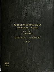
RECONSTRUCTION OF CALORIMETER.<br />
It waB, there<strong>for</strong>e, decided that, in<br />
order to obtain the desired results from<br />
this engine, it would be necessary to cut<br />
down the amount <strong>of</strong> water contained in the<br />
<strong>calorimeter</strong>, <strong>an</strong>d also by-pass the spraying<br />
chamber, <strong>an</strong>d cut out several passes. A draw-<br />
ing <strong>of</strong> the reconstructed <strong>calorimeter</strong> is shown<br />
on the proceeding page.<br />
To facilitate more inst<strong>an</strong>t<strong>an</strong>eous<br />
operation the qu<strong>an</strong>tity <strong>of</strong> water was out down<br />
in the lower wet pass by shortening the nip-<br />
ple on the water seal, <strong>an</strong>d by bending over<br />
the saw tooth edges so that a minimum amount<br />
<strong>of</strong> water was stored on the baffles.<br />
A photograph <strong>of</strong> the reconstructed<br />
baffle is shown on page 32.<br />
After the above-mentioned ch<strong>an</strong>ges<br />
had been made, <strong>an</strong>other complete run was made.
• . '<br />
,<br />
,' ; [<br />
)o led<br />
- :•<br />
- - - ,, .<br />
_ •<br />
- ;<br />
•<br />
•<br />
$ j<br />
- .' lx ed 'o<br />
,<br />
•<br />
r - -<br />
-<br />
,-'..' oat<br />
;<br />
'•<br />
.<br />
;•<br />
-
- .<br />
- •<br />
o-<br />
' '<br />
:<br />
"<br />
'<br />
'<br />
.' ;<br />
-<br />
'<br />
•' . ..<br />
' o<br />
_<br />
. ' .<br />
'<br />
)0 led '<br />
"<br />
'.<br />
• • :<br />
1c<br />
-<br />
-<br />
'<br />
.<br />
.<br />
'<br />
'-<br />
'o
^I > '<br />
^gWF<br />
1<br />
w o<br />
e:<br />
"0— o—cr<br />
EECONS TRUCTED<br />
MEW Of<br />
CALORIMETER.<br />
'9
-sa-<br />
lt was found that the previous men-<br />
tioned objections, the bulging, breathing<br />
<strong>an</strong>d refrigerating effect <strong>an</strong>d the short cir-<br />
cuiting <strong>of</strong> <strong>gas</strong>es through the exit pipe <strong>an</strong>d<br />
the lag <strong>of</strong> the <strong>calorimeter</strong> had been remedied.<br />
During the preliminary run <strong>an</strong>d the<br />
run be<strong>for</strong>e the <strong>calorimeter</strong> was reconstructed,<br />
the brake arm rested on two places. This<br />
made the results <strong>of</strong> the first two tests un-<br />
reliable, <strong>an</strong>d were, there<strong>for</strong>e, discarded.<br />
Another notch was filed in the brake<br />
arm, <strong>an</strong>d the brake const<strong>an</strong>t recalculated.
.<br />
•<br />
1
&L//ZAT/OA/ O^/Vt/A<br />
NET L OAE> O/ZBR,<br />
GA*S coA/sv/*r£~z><br />
CAUDRfT/C WLUE<br />
JXCXZT WATER /<br />
GAS RER HR<br />
{5/15 ATMETER<br />
BAROMETER*<br />
CALOR/METE'R W*n<br />
^URRl. V VMTE><br />
JACKET IMTE><br />
GAS AT A/ETTER<br />
ROOM<br />
£7XH4ust<br />
CALO&/A4ET&/? VYATi<br />
R. 7=> M.<br />
£j(RLo&/CA/& RER /<br />
A*£"./?<br />
/.HP<br />
&.H&<br />
AiECH etr^<br />
//EAT &URR/-fEZ> F<br />
//EAT /N JACKET<br />
HE^T/AT ^EXHAUST<br />
HEAT EQUtWt.&ST<br />
HEMT //V J/tC/TET<br />
HEAT /A/ EXH^t/JT<br />
HEAT R&? Af/P<br />
HEAT /a/EXH*rcS7- (c.
-<br />
-<br />
!
-38-<br />
RUN NUMBER 1.<br />
During this run the mixing valve<br />
was inadvertently ch<strong>an</strong>ged so that this data,<br />
when plotted, as shown in Figure 7, Page 37,<br />
did not give uni<strong>for</strong>m results.<br />
There was considerable leakage <strong>of</strong><br />
<strong>exhaust</strong> <strong>gas</strong> <strong>an</strong>d water in the top <strong>of</strong> the spray<br />
ing chamber, due to back pressure. As the <strong>gas</strong><br />
had already given up its heat to the water,<br />
<strong>an</strong>d as the water at this point had received<br />
very little heat from the <strong>gas</strong>, it was decided<br />
to neglect this entirely.
"<br />
;<br />
'<br />
-'.'.'•:'<br />
*!<br />
r<br />
.<br />
c
7~l<br />
Dl/RAT/QA/ O/<br />
A/£T LOAID OH<br />
GAS C0/V*SUME\<br />
CALOWE/C i/j4<br />
JACKET MATE<br />
Gy4S 7=>E.fi? A//?<br />
GAS AT MET?<br />
BA/t'oajeter<br />
CALOf?/MER VM7<br />
SUPPl-V /M-£T<br />
JACKET OUTCt<br />
dS AT MET£Ti<br />
~ROO/*f TSAtf*<br />
EX/-f.<br />
ACTUAL MR<br />
ACTUAL B /¥=><br />
METCA/.<br />
3771/. St/PPJ-K<br />
RET^T /A/ yJXC<br />
HEAT /A/ £2XH<br />
EQU/lfA<br />
/A/ &XM<br />
" •• JACM<br />
£XH*
;<br />
-<br />
r<br />
;<br />
'
-43-<br />
RUN NUMBER 2,<br />
During this run the mixing valve was<br />
set in one position, <strong>an</strong>d care was taken that<br />
its adjustment was not ch<strong>an</strong>ged.<br />
When the engine was run at its rated<br />
power considerable trouble was experienced in<br />
making the engine hold its load. Its oper-<br />
ation was accomp<strong>an</strong>ied by occasional back-<br />
firing. However, as the greater part <strong>of</strong> the<br />
run had been made it was decided to continue<br />
the run with the same mixing valve adjustment.<br />
The <strong>gas</strong> consumption was also higher<br />
th<strong>an</strong> on the previous run<br />
.<br />
No trouble was experienced in keeping<br />
the <strong>calorimeter</strong> temperatures at the desired<br />
points.<br />
During this <strong>an</strong>d the previous run<br />
light spring cards were taken, in order to<br />
obtain the back pressure caused by the cal-
T" C J OX ••-- -<br />
- '<br />
[ ':'-<br />
'''<br />
_r r :<br />
!<br />
:<br />
'<br />
v<br />
.<br />
-<br />
c<br />
. .<br />
:<br />
• ' '<br />
'.<br />
'<br />
[<br />
-<br />
,
-44-<br />
orimeter, Several <strong>of</strong> these cards are shown on<br />
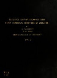
Page 45. The back pressure was about .8 <strong>of</strong><br />
a pound at rated load.<br />
The cards taken at full load, with a<br />
240 pound spring, shown on Page 46, show clear<br />
ly the irregularity <strong>of</strong> the action <strong>of</strong> the mix-<br />
ing valve. These cards were taken from cut-<br />
out to cut-out. The M.E.P. decreased with<br />
the increase in load.<br />
The heat bal<strong>an</strong>ce was plotted <strong>for</strong> both<br />
runs, in terms <strong>of</strong> the percent <strong>of</strong> total heat.<br />
The <strong>exhaust</strong> <strong>gas</strong> loss was then calcu-<br />
lated rationally , <strong>an</strong>d also plotted.<br />
The method <strong>of</strong> calculating the var-<br />
ious losses is clearly shown on the preceding<br />
pages.
EC [O<br />
-<br />
. d<br />
'<br />
-<br />
-<br />
r<br />
'<br />
--.'•<br />
.<br />
'<br />
: 1 Itfl d I<br />
' o<br />
- J £ [ i<br />
n&o<br />
c<br />
•<br />
'<br />
: I<br />
-<br />
d 3*1 d<br />
exlT _<br />
.<br />
<<br />
. evl
FIg./O. J3ack Ftec&tiUKe: Ca/?d<br />
fft/A/ *2 Fc/l,l. Load.
-45*<br />
In using the rational equations<br />
previously mentioned the voume <strong>of</strong> mixture<br />
was found by multiplying the piston displace-<br />
ment by the number <strong>of</strong> explosions <strong>an</strong>d the<br />
temperature <strong>of</strong> the <strong>exhaust</strong>. The heat lost in<br />
the <strong>exhaust</strong> per hour is found by multiplying<br />
the weight <strong>of</strong> the <strong>exhaust</strong> <strong>gas</strong>es per hour, by<br />
the specific heat, <strong>an</strong>d by the temperature<br />
ch<strong>an</strong>ge. This c<strong>an</strong> be expressed by the follow-<br />
ing <strong>for</strong>mulae: B.T.U./ hr. = WSQtT-ffi 1<br />
1 cu.ft.<br />
'.There W = weight A<strong>of</strong> mixture pep fer.<br />
B£ = no. <strong>of</strong> cu. ft. <strong>of</strong> mix./hr.<br />
S- Specific heat <strong>of</strong> mixture<br />
T = temp, <strong>of</strong> Exhaust <strong>gas</strong>es<br />
ffi*= temp <strong>of</strong> room.<br />
)
i<br />
-<br />
-<br />
,<br />
. 5
Load. /^W »/. /££?/? 34.5 Lss.<br />
Hg /3<br />
/pis/v . **£. F~ci_l. Load Ca&ds.<br />
M.E.f* 68.5 LBS.
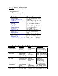
CALCULATED HEAT IN EXHAUST GAS<br />
Toatal displ = vol piston diapl x EPMx 60<br />
= 6.75 x.6.75 x 5.14 x 11.94x60x 35.5<br />
4<br />
= 1805 cu ft per hour.<br />
Gas per hour = from log.<br />
Air per hour = Total rlispl - <strong>gas</strong> per hour<br />
= 1805 - 224.5 = 1580.7<br />
Air / hr. lbs= Air /hr cu ft<br />
14.2<br />
= 1580.7 =11.5 lbs /hr.<br />
14.2<br />
Gas / hr.lbs = <strong>gas</strong> per hr. cu. ft x .084<br />
= 224.5 x 0.084 = 18.8<br />
Total lbs = 111.3 piU s ie.8 = 130.1<br />
BTD in EXH = lbs. exh <strong>gas</strong> x diff tempxSpec H<br />
= 130.1x(900~60) x 0.084<br />
= 25,700<br />
% lost in Exh= 25.700 = 16.3 t<br />
158000
.<br />
.<br />
-<br />
.<br />
'<br />
.<br />
- .<br />
. .<br />
.
SAMPLE CALCULATIONS<br />
Cu'.FT.GAS/HR. = GAS C ON.x ABS TEMP x ST. PR.<br />
ST.ABS~.TEMF x PR. AT METER<br />
IS. 7 x 5 80 x 50 x 1 2 = 224.3 cu.ft/ hr.<br />
522 x 29.98<br />
'<br />
Cu f t / hr x heat value <strong>gas</strong> = BTU supplied/hr.<br />
224.3 x 705 = 158,000. BTU supplied / hr.<br />
I.H.P. x 2546 = heat equiv <strong>of</strong> IHP.<br />
10.6 x 2546 = heat equiv <strong>of</strong> IHPl<br />
Heat equiv = $ heat in IHP.<br />
Heat supplied<br />
25.900 = % heat in IHP.<br />
158,000<br />
Diff. in temp, x water / hr. = BTU in Exhaust<br />
(82.5-53) x 99.5 x 12 = 35,160 BTU in Exhaust<br />
35' 160 = 22.8 ic heat lost in Exhaust<br />
158,000<br />
Diff in temp x Jacket water /hr. =BTU jacket<br />
(102 -53) x 74.5 x 12 = 43,800 BTU in Jacket<br />
45.800 = 27.7 fo heat lost in Jacket water<br />
158000
.<br />
.
PART FOUR<br />
CONCLUSIONS
-52.<br />
The heat <strong>of</strong> the <strong>exhaust</strong> <strong>gas</strong> as cal-<br />
culated rationally was about ten per-cent<br />
lower throughout both runs th<strong>an</strong> that obtain-<br />
ed by me<strong>an</strong>s <strong>of</strong> the <strong>calorimeter</strong>. This shows<br />
that either the me<strong>an</strong> specific heat or the<br />
temperature difference or both were assumed<br />
incorrectly.<br />
Assuming that the <strong>exhaust</strong> temperature<br />
was 900 deg.F., the me<strong>an</strong> specific heat <strong>of</strong> the<br />
<strong>gas</strong> should have been assumed as 0.312, or if<br />
the me<strong>an</strong> specific heat was correct at 0.245,<br />
the temperature <strong>of</strong> the <strong>exhaust</strong> <strong>gas</strong> should have<br />
been assumed as 1250 deg.P.
_<br />
-<br />
id<br />
. . .