I II IV III VI V VII
I II IV III VI V VII
I II IV III VI V VII

Create successful ePaper yourself
Turn your PDF publications into a flip-book with our unique Google optimized e-Paper software.
PHOENIX MECANO<br />
Elektrozylinder und Hubsäulen<br />
Electric cylinders and lifting devices
Inhaltsverzeichnis<br />
Content<br />
I. Produktauswahl Product presentation............................................4-5<br />
<strong>II</strong>. Antriebe Actuators<br />
Antriebseinheit LZ S/P Drive unit LZ S/P...................................................................2-5<br />
<strong>II</strong>I. Hubsäulen Lifting devices<br />
Multilift Multilift ..............................................................................2-13<br />
I-2<br />
Merkmale Features...........................................................................2-5<br />
Technische Daten Technical data.................................................................6-8<br />
Zubehör Accessories ....................................................................9-13<br />
Alpha Colonne Alpha Colonne.................................................................14-19<br />
Merkmale Features.......................................................................14-15<br />
Technische Daten Technical data ............................................................16-17<br />
Zubehör Accessories ..................................................................18-19<br />
LAMBDA Colonne LAMBDA Colonne............................................................20-25<br />
Merkmale Features.......................................................................20-21<br />
Technische Daten Technical data ............................................................22-23<br />
Zubehör Accessories ..................................................................24-25<br />
RKPowerlift RKPowerlift......................................................................26-35<br />
Merkmale Features.......................................................................26-27<br />
Technische Daten Technical data ............................................................28-32<br />
Zubehör Accessories ..................................................................33-35<br />
RKSlimlift RKSlimlift .........................................................................36-44<br />
Merkmale Features.......................................................................36-37<br />
Technische Daten Technical data..................................................................38<br />
Zubehör Accessories ..................................................................39-44
PHOENIX MECANO I<br />
<strong>IV</strong>. Elektrozylinder Electric cylinders<br />
LAMBDA Elektrozylinder LAMBDA electric cylinder ...................................................2-7<br />
Merkmale Features...........................................................................2-4<br />
Technische Daten Technical data....................................................................5<br />
Zubehör Accessories ......................................................................6-7<br />
Baugruppe M9 Series M9............................................................................8-10<br />
Merkmale Features...........................................................................8-9<br />
Technische Daten Technical Data .................................................................10<br />
Baugruppe 010 Series 010 .........................................................................12-15<br />
Merkmale Features.......................................................................12-14<br />
Technische Daten Technical Data ............................................................14-15<br />
Baugruppe 015 Series 015 ........................................................................16-18<br />
Merkmale Features.......................................................................16-17<br />
Technische Daten Technical Data .................................................................18<br />
Elektrozylinder LZ 60 Electric cylinder LZ 60......................................................20-28<br />
Merkmale Features............................................................................20-21<br />
Technische Daten Technical Data .................................................................22-25<br />
Zubehör Accessories .......................................................................25-28<br />
V. Steuerungen Positioning controls<br />
Trafosteuerung 120 VA Transformer 120 VA ............................................................2-3<br />
Trafosteuerung 160 VA Transformer 160 VA ......................................................3.1-3.2<br />
MultiControl mono MultiControl mono .............................................................4-5<br />
MultiControl duo MultiControl duo.................................................................6-7<br />
MultiControl quadro MultiControl quadro ...........................................................8-9<br />
Trafosteuerung f. LAMBDA-Antriebe Transformer for LAMBDA-drives....................................10-11<br />
Synchronsteuerung f. LAMBDA-Antriebe Synchronous transformer for LAMBDA-drives ..............12-13<br />
SPS-/PC-Datenschnittstelle PLC-PC-data interface .....................................................14-16<br />
<strong>VI</strong>. Systeme Systems<br />
RK Easylift RK Easylift ............................................................................2-5<br />
Merkmale Features................................................................................2-3<br />
Zubehör Accessories...............................................................................4<br />
V<strong>II</strong>. Anhang Appendix<br />
Glossar Glossary ................................................................................2-3<br />
Fax-Anfrage Fax inquiry ...........................................................................4-5<br />
I-3<br />
<strong>II</strong><br />
<strong>II</strong>I<br />
<strong>IV</strong><br />
V<br />
<strong>VI</strong><br />
V<strong>II</strong>
Produktauswahl<br />
Product presentation<br />
Die Phoenix Mecano entwickelt und fertigt seit vielen<br />
Jahren Antriebe. Hierbei liegt Produktschwerpunkt<br />
bei Hubsäulen und Elektrozylindern.<br />
Die Hubsäulen eignen sich besonders für die lineare<br />
Verstellung von Schreib- und Labortischen, Montagevorrichtungen<br />
und Handhabungsapparaten. Auf diese<br />
Weise können Arbeitsplattformen und Montagehilfen<br />
in die ergonomisch günstigste Position gebracht<br />
werden.<br />
Die Elektrozylinder stellen eine sehr gute alternative<br />
zu den Pneumatikzylindern dar.<br />
Folgende Vorteile heben sich besonders hervor:<br />
Gleichmäßiger Lauf auch bei geringen Geschwindigkeiten<br />
Keine Leckverluste; weniger Energieverbrauch<br />
Selbsthemmung bei Stillstand<br />
Teure Zukaufteile wie Magnetventile, Drosseln<br />
oder Wartungseinheiten werden nicht benötigt<br />
Keine Abluftgeräusche<br />
I-4<br />
Phoenix Mecano has been developing and manufacturing<br />
drive systems for many years. Main items of its<br />
product range are lifting columns and electric cylinders.<br />
Lifting devices and electric cylinders build an important<br />
part of our drive product range.<br />
Our lifting devices are particularly suitable for the linear<br />
moving of desks, laboratory tables, assembly<br />
equipment and handling devices. They allow for optimal<br />
ergonomic adjustment of work tpaltforms and assembly<br />
equipments.<br />
Electric cylinders are a very good alternative to pneumatic<br />
cylinders. In particular the following advantages<br />
have been observed:<br />
regular run also at low speed<br />
no risk of leak; lower power consumption<br />
self-locking device<br />
expensive supplementary parts such as solenoid<br />
valves, chokes or maintenance devices are not<br />
necessary.<br />
no evacuation noises<br />
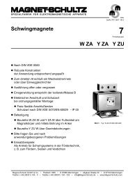
Mit Hilfe der nachstehenden Vergleichsdiagramme<br />
wird Ihnen eine Möglichkeit geschaffen, nach unterschiedlichen<br />
Kriterien eine Produktvorauswahl zu<br />
treffen.<br />
Die Angaben beziehen sich auf die Standardprodukte.<br />
Auf Anfrage sind jedoch auch spezielle Ausführungen<br />
(z.B. größerer Hub, größere Hubkraft,<br />
höhere Verfahrgeschwindigkeit usw.) erhältlich.<br />
The following diagram will allow you to make a<br />
first choice according to different criteria.<br />
The figures refer to standard models. However,<br />
special models (e.g. with greater travel lengths,<br />
lifting power, stroke speed etc.) can be provided<br />
upon request.
6.000<br />
4.000<br />
3.500<br />
3.000<br />
2.500<br />
2.000<br />
1.500<br />
1.000<br />
500<br />
900<br />
700<br />
600<br />
500<br />
400<br />
300<br />
200<br />
100<br />
0<br />
0<br />
Multilift<br />
Hub [mm]<br />
Travel [mm]<br />
Multilift<br />
Dynamische Hubkraft [N]<br />
Dynamic lifting power<br />
Alpha Colonne<br />
Alpha Colonne<br />
LAMBDA Colonne<br />
LAMBDA Colonne<br />
RK Powerlift<br />
RK Powerlift<br />
RK Slimlift<br />
RK Slimlift<br />
RK Easylift<br />
RK Easylift<br />
LAMBDA E-Zyl.<br />
M9<br />
M10<br />
LH10<br />
LH11<br />
LH950<br />
Lh15<br />
LZ60<br />
LAMBDA E-Zyl.<br />
M9<br />
M10<br />
LH10<br />
LH11<br />
LH950<br />
LH15<br />
LZ60<br />
100<br />
50<br />
35<br />
30<br />
25<br />
20<br />
15<br />
10<br />
5<br />
0<br />
1300<br />
800<br />
700<br />
600<br />
500<br />
400<br />
300<br />
200<br />
100<br />
0<br />
Geschwindigkeit* [mm/s]<br />
Speed* [mm/s]<br />
Multilift<br />
Einbaumaß [mm]<br />
Installation height [mm]<br />
Multilift<br />
Alpha Colonne<br />
Alpha Colonne<br />
LAMBDA Colonne<br />
LAMBDA Colonne<br />
RK Powerlift<br />
RK Powerlift<br />
RK Slimlift<br />
RK Slimlift<br />
PHOENIX MECANO I<br />
*bei den Katalogangaben sind ±10% Toleranz<br />
zu berücksichtigen<br />
RK Easylift<br />
RK Easylift<br />
LAMBDA E-Zyl.<br />
M9<br />
M10<br />
LH10<br />
LH11<br />
LH950<br />
LH15<br />
LZ60<br />
LAMBDA E-Zyl.<br />
M9<br />
M10<br />
LH10<br />
LH11<br />
LH950<br />
LH15<br />
LZ60<br />
I-5<br />
<strong>II</strong><br />
<strong>II</strong>I<br />
<strong>IV</strong><br />
V<br />
<strong>VI</strong><br />
V<strong>II</strong>
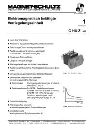
Anwendungen<br />
Applications<br />
I-6<br />
Höhenverstellbarer Geräteträger mit<br />
RKPowerlift (Sonderausführung)<br />
Height-adjustable instrument rack<br />
with RKPowerlift (special version)<br />
Dialyseliege: Verstellung der Positionen über vier Elektrozylinder<br />
LZ 60 P.<br />
Dialysis couch: positioning by means of four electric<br />
cylinders LZ 60 P.<br />
Hebebühne aus Multilift-Komponenten<br />
Lifting platform made of Multilift components
Zur Verstellung der Linearkomponenten aus<br />
dem PM-Programm stehen elektrische Antriebe<br />
zur Verfügung, die aber auch für<br />
andere Anwendungen genutzt werden und<br />
zu diesem Zweck in individuelle Systeme<br />
einfließen können.<br />
The electric actuators designed for the<br />
height adjustment of linear components of<br />
PM product range can be also used in other<br />
applications and thus in customised solutions.<br />
Antriebe<br />
Actuators<br />
PHOENIX MECANO<br />
1
Antriebseinheit LZ S/P<br />
Drive unit LZ S/P<br />
Die neuen leistungsstarken Antriebseinheiten der<br />
Baureihe LZ S (Stabform) und LZ P (Parallel montierter<br />
Motor) dienen der Ansteuerung von Linearachsen.<br />
Durch ein sehr gutes Preis-/Leistungsverhältnis sind<br />
diese Antriebe auch als Alternative zu der herkömm-l<br />
ichen Handradverstellung zu sehen. Einsatzbereiche<br />
sind hierbei zum Beispiel der Einrichtbetrieb von<br />
Maschinen oder Arbeiten in Gefahrenbereichen.<br />
Standardmäßig können verschiedenste Steuerungen<br />
und Handschalter angeschlossen und somit den Anforderungen<br />
angepasst werden.<br />
Merkmale<br />
<strong>II</strong> - 2<br />
Antriebseinheit LZ P<br />
Drive unit LZ P<br />
Drehzahlregelung mit MultiControl mono möglich<br />
(bei elektr. Anschluss “a”)<br />
Bis zu 25 Memorypositionen mit RK-Synchronsteuerung<br />
speicherbar (bei elektr. Anschluss “c”)<br />
Synchrone Verfahrbewegung möglich<br />
Kompakte Bauform<br />
Gehäuse aus Aluminium<br />
Formschönes Design<br />
LZ S<br />
LZ P<br />
Endschalteranschluss<br />
connection for limit switch<br />
Antriebseinheit LZ S<br />
Drive unit LZ S<br />
The new series of high-performance drive units LZ S<br />
(bar-shaped) and LZ P (parallel mounted motor) are<br />
utilised to drive linear actuators.<br />
Thanks to their excellent price / performance ratio,<br />
these drive units can be considered as an alternative to<br />
the traditional handwheels. Here, ideal application<br />
fields are for istance adjusting and positioning<br />
maschines or working on machines situated in dangerous<br />
areas.<br />
A great variety of controllers and hand switches can be<br />
connected as standard, thus satisfying any demand.<br />
Features<br />
speed control via MultiControl mono (with electrical<br />
connection "a")<br />
up to 25 Memory positions can be memorized by<br />
means of the RK synchronous control (with electrical<br />
connection "c")<br />
synchronous positioning<br />
compact dimensions<br />
aluminium enclosure<br />
attractive design<br />
Endschalteranschluss<br />
connection for limit switch
Technische Daten<br />
Spannung 24-36 V DC<br />
Stromaufnahme max. 4,5 A<br />
Schutzart IP 54<br />
Umgebungstemperatur -10°C...+60°C<br />
Einschaltdauer<br />
Die Einschaltdauer ist abhängig von der Belastung und<br />
der Umgebungstemperatur. Bei maximaler Belastung<br />
reduziert sich die Einschaltdauer von 75% im Leerlauf<br />
(18,5 Min. Betriebszeit, 6,5 Min. Ruhezeit) auf 20%<br />
(10 Min. Betriebszeit, 30 Min. Ruhezeit).<br />
Leistungsdiagramm*<br />
Performance diagram*<br />
Relation zwischen:<br />
Drehzahl/Abtriebsmoment<br />
bzw. Stromaufnahme<br />
Ratio lifting power/stroke<br />
speed<br />
*alle Angaben wurden mit einer PM-Trafosteuerung (bei Raumtemperatur)<br />
ermittelt. Bei Betrieb an einer Festspannungsquelle<br />
können die Werte geringfügig variieren.<br />
*all specifications have been investigated with a PM transformer<br />
control at ambient temperature. The values might slightly vary<br />
when using a fixed voltage source.<br />
elektr. Anschluss wahlweise<br />
electrical connection at your choice<br />
“a” “b”<br />
Anschluss (2,5m) an PM-Trafosteuerung,<br />
MultiControl mono<br />
oder externe Festspannungsquelle.<br />
Nur Anschlusskabel<br />
herausgeführt.<br />
Connection to PM transfomer<br />
control, MultiControl mono or<br />
to an external fixed voltage<br />
source.<br />
Only by means of a connection<br />
cable (2,5m).<br />
Code No. Type<br />
Alle Anschlusskabel (ca. 1m)<br />
direkt herausgeführt (Motor,<br />
2-Kanal-Hallsensor) z.B. zum<br />
Anschluss an eine SPS.<br />
All connections cables (ca. 1m)<br />
are directly lead through<br />
(motor, 2-circuit Hall sensor)<br />
e.g. connection to a PLC.<br />
elektr. Anschluss<br />
electric. connection<br />
Technical data<br />
PHOENIX MECANO I<br />
Voltage 24-36 V DC<br />
Current consumption max. 4,5 A<br />
Protection class IP 54<br />
Ambient temperature -10°C...+60°C<br />
Duty cycle<br />
The duty cycle depends on the loads and the ambient<br />
temperature. When idle running under max. load the<br />
duty cycle decreases from 75% (18.5 min. operating<br />
time, 6.5 min. break) to 20% (10 min. operating time,<br />
30 min. break).<br />
200<br />
150<br />
100<br />
50<br />
-1<br />
n [min ]<br />
Ausf. Version LZ-S<br />
LZ-S<br />
LZ-P<br />
0,9 1,8 2,7 3,6 4,5 I [A]<br />
2 3 4 5 6 7 M [Nm]<br />
Ausf. Version LZ-P 1 2 3 4 5 6 M [Nm]<br />
“c”<br />
Anschluss (2,5m) an<br />
PM-Synchronsteuerung<br />
Connection cable (2,5m) to a<br />
PM synchronous control<br />
max. Abtriebsmoment<br />
max. driving torque<br />
max. Drehzahl<br />
max. speed<br />
9.0980 LZ S a 5 Nm 160 min -1<br />
9.0981 LZ S b 5 Nm 160 min -1<br />
9.0984 LZ S c 5 Nm 160 min -1<br />
9.0982 LZ P a 4 Nm 196 min -1<br />
9.0983 LZ P b 4 Nm 196 min -1<br />
9.0985 LZ P c 4 Nm 196 min -1<br />
Hinweis: Die Antriebseinheiten<br />
dürfen nicht auf “Block”<br />
gefahren werden! An alle<br />
Varianten können Kundenseitig<br />
Endschalter angeschlossen<br />
werden. Ein Betrieb ohne<br />
Endschalter ist möglich, wird<br />
aber nicht empfohlen.<br />
Please note: the drive unit is not<br />
to be driven to the end stop!<br />
The user can apply limit<br />
switches to any version.<br />
Functioning without limit<br />
switches is possible but not<br />
recommended.<br />
Gewicht<br />
weight<br />
1,8 kg<br />
1,8 kg<br />
1,8 kg<br />
3,0 kg<br />
3,0 kg<br />
3,0 kg<br />
<strong>II</strong> - 3<br />
<strong>II</strong><br />
<strong>II</strong>I<br />
<strong>IV</strong><br />
V<br />
<strong>VI</strong><br />
V<strong>II</strong>
Antriebseinheit LZ S/P<br />
Drive unit LZ S/P<br />
Steuerungen<br />
Positioning controls<br />
Eingangsspannung 230 V AC<br />
Ausgangsspannung 24 V DC, 36 V DC<br />
Input voltage 230 V AC<br />
Output voltage 24 V DC, 36 V DC<br />
<strong>II</strong> - 4<br />
Code No. Ausführung Version<br />
qza 07 c 13 bq 021<br />
qst 35 c 01 aa 000<br />
qst 35 c 02 aa 000*<br />
qst 35 c 04 aa 000*<br />
Trafosteuerung 120 VA, bis max. 3 A Stromabgabe bei 10% Einschaltdauer<br />
transformer 20 VA, up to max. 3 A current consumption with 10% duty cycle<br />
MultiControl mono, bis max. 10 A Stromabgabe bei 15% ED, 24/36 V DC<br />
MultiControl mono, up to max. 10 A current consumption with 15%d.c., 24/36 V DC<br />
Synchronsteuerung MultiControl duo, bis max.12 A Stromabgabe bei 15% ED<br />
synchr. control MultiControl duo, up to max.12 A current consumpt. with 15%d.c.<br />
Synchronsteuer. MultiControl quadro, bis max. I= 12 A Stromabgabe bei 15%ED<br />
synchr. contr. MultiControl quadro, up to max. I= 12 A current consumpt.with 15%d.c.<br />
*zur Anbindung einer Synchronsteuerung wird der Anschluss “c”<br />
an der Antriebseinheit benötigt.<br />
Handschalter<br />
Hand switches<br />
Trafost. 120 VA<br />
transf. control 120 VA<br />
ca. 24 V DC<br />
MultiControl<br />
ca. 36 V DC<br />
bis 2 Antriebe steuerbar<br />
controls up to 2 drives<br />
bis 2 Antriebe steuerbar<br />
controls up to 2 drives<br />
1-2 Antriebe synchron<br />
1-2 synchronous drives<br />
1-4 Antriebe synchron<br />
1-4 synchronous drives<br />
*connection "c" is required to connect a synchronous control to<br />
the drive unit.<br />
Code No. Ausführung Version Abb. ill.<br />
Handschalter für Trafosteuerung Hand switch for transformer control<br />
qzb 02 c 03 ad 031<br />
qzb 02 c 03 ad 011<br />
Handschalter mit 1m Spiralkabel – 6 Funktionstasten<br />
hand switch with 1m helix cable – 6 function keys<br />
Infrarot-Fernbedienung – 6 Funktionstasten<br />
infrared remote control – 6 function keys<br />
Handschalter für Trafo- oder Synchronsteuerung Hand switch for transformer or synchronised control<br />
qzb 02 c 03 ab 031<br />
qzb 02 c 03 ab 011<br />
qzb 00 d 04 ab 041<br />
qzb 02 c 01 ae 034<br />
Handschalter mit 1m Spiralkabel – 2 Funktionstasten<br />
hand switch with 1m helix cable – 2 function keys<br />
Infrarot-Fernbedienung – 2 Funktionstasten<br />
infrared remote control – 2 function keys<br />
Handschalter mit 1m Spiralkabel – 2 Funktionstasten<br />
hand switch with 1m helix cable – 2 function keys<br />
Fußschalter – 2 Funktionstasten<br />
Foot switch – 2 function keys<br />
Handschalter für Synchronsteuerung Hand switch for synchronised control<br />
qzb 00 d 04 ad 041<br />
1 2<br />
3<br />
4 5 6 7<br />
Handschalter mit 1m Spiralkabel – 6 Funktionstasten<br />
hand switch with 1m helix cable – 6 function keys<br />
Zubehör für Handschalter mit Spiralkabel Accessories for hand switch with helix cable<br />
2 Antriebe getrennt oder gemeinsam steuerbar<br />
controls 2 drives, separate or joint<br />
2 Antriebe getrennt oder gemeinsam steuerbar<br />
controls 2 drives, separate or joint<br />
bis zu 2 Antriebe gemeinsam steuerbar<br />
controls up to 2 drives simultaneously<br />
bis zu 2 Antriebe gemeinsam steuerbar<br />
controls up to 2 drives simultaneously<br />
mehrere Antriebe steuerbar<br />
controls several drives<br />
bis zu 2 Antriebe steuerbar<br />
controls up to 2 drives<br />
mehrere Antriebe synchron steuerbar<br />
Höhe wird auf dem LCD-Display angezeigt<br />
several drives synchronously controllable<br />
position indicated on LED display<br />
qzd 000 072 Halterung für Handschalter support for hand switch 3<br />
qzd 000 074 Handschalterschublade hand switch drawer 8<br />
Zubehör für Synchronsteuerung Accessories for synchronised control<br />
qzd 100 108 SPS-/PC-Datenschnittstelle PLC-/PC data interface 10<br />
8<br />
9<br />
2<br />
5<br />
1<br />
4<br />
6<br />
9<br />
7<br />
10
Endschalter<br />
Limit switch<br />
Max. Spannung 250 V AC<br />
Max. Schaltstrom 6 A<br />
Max. Einschaltstrom 16 A<br />
Schalthäufigkeit max. 6000/h<br />
Lebensdauer 1x10 7 Schaltzyklen<br />
Achshebelverstellung einrastend um 360°<br />
Schutzart IP 65<br />
Umgebungstemperatur -30°C...+80°C<br />
Motoradapter an RK-Lineareinheiten<br />
Motor adaptor for RK linear units<br />
Anwendungsbeispiel: Antriebseinheit LZP in<br />
Kombination mit einer Rohrsystem Lineareinheit E<br />
Application example: drive unit LZP combined with a<br />
tube linear unit E<br />
weitere Adapter auf Anfrage erhältlich<br />
further adapters on request available<br />
Lineareinheit<br />
an<br />
linear unit<br />
LZ S<br />
Code No.<br />
LZ P<br />
Code No.<br />
Kupplung<br />
Code No.<br />
coupling<br />
Code No.<br />
Lineareinheit<br />
an<br />
linear unit<br />
LZ S<br />
Code No.<br />
PHOENIX MECANO I<br />
LZ P<br />
Code No.<br />
Kupplung<br />
Code No.<br />
coupling<br />
Code No.<br />
E 30 949700 949701 9109200810 EP(X) 60 949716 – 9114301014<br />
E 40 949702 949703 9114301012 EP(X) 80 949717 – 9119401020<br />
E 50 949704 949705 9114301012 EV 30 949720 949721 9109200810<br />
E 60 949706 – 9114301014 EV 40 949722 949723 9114301010<br />
E 80<br />
auf Anfrage<br />
on request<br />
– 9119401020 EV 50 949724 949725 9114301012<br />
EP(X) 30 949710 949711 9109200810 EV 60 949726 949727 9114301012<br />
EP(X) 40 949712 949713 9114301012 EV 80 949728 949729 9114301014<br />
EP (X) 50 949714 – 9114301012<br />
Max. voltage 250 V AC<br />
Max. constant current 6 A<br />
Max. starting current 16 A<br />
Switching frequency max. 6000/h<br />
Lifetime 1x10 7 switching cycles<br />
Lever locking at 360°<br />
Protection class IP 65<br />
Ambient temperature -30°C...+80°C<br />
Code No. Ausführung Version<br />
91900 Öffner/Schließer NC/NO<br />
<strong>II</strong> - 5<br />
<strong>II</strong><br />
<strong>II</strong>I<br />
<strong>IV</strong><br />
V<br />
<strong>VI</strong><br />
V<strong>II</strong>
Anwendungsbeispiele<br />
Application examples<br />
Etikettiermaschine: Die Höhenanpassung wird durch eine<br />
Lineareinheit der Baureihe E mit EHL geregelt.<br />
Labelling machine: The production process is controlled by<br />
means of a linear unit E with EHL.<br />
Transfersystem: Antrieb einer Materialzuführung<br />
Transfer system: drive element for feeder unit<br />
<strong>II</strong> - 6<br />
Röntgengerät: Seitenverstellung über EHL mit RK DuoLine S,<br />
Höhenverstellung über RK Easylift.<br />
X-ray machine: lateral adjustment by means of EHL with RK<br />
DuoLine S, heigt adjustment by means of RK Easylift.
Teleskopierende Hubsäulen können zur<br />
Höhenverstellung von Arbeitsplattformen<br />
und Betriebsmitteln genutzt werden, um<br />
eine ergonomisch günstige Position zu<br />
erreichen. Unterschiedliche Bauformen<br />
und Ausführungen finden sowohl in der<br />
Industrie als auch im Büromöbelbereich<br />
Anwendung.<br />
Telescopic lifting columns are used for the<br />
height adjustment of working platforms or<br />
equipments in order to fulfil ergonomic<br />
requirements. Due to their manifold designs<br />
and speed versions these columns are<br />
suitable for use in industrial as well as<br />
office furniture sector.<br />
Hubsäulen<br />
Lifting devices<br />
PHOENIX MECANO<br />
1
Multilift<br />
Multilift<br />
Merkmale<br />
<strong>II</strong>I - 2<br />
Ausführung A<br />
Version A<br />
Ausführung B, m. Ausfräsung<br />
Version B, with milled slots<br />
Höhenverstellung von Montagetischen und Vorrichtungen<br />
Alu-Strangpressprofil mit Längsnuten<br />
Vierfache Lagerung mit POM-Gleitlagerschalen<br />
Leistungsstarker Gleichstrommotor<br />
Integrierte Endschalterleiste zur Hubbegrenzung<br />
Selbsthemmung auch bei max. Belastung<br />
Profiloberfläche hell eloxiert, als Option farbig<br />
pulverbeschichtet<br />
Einzel- und Synchronsteuerung möglich<br />
Spezielle Hublängen auf Anfrage<br />
Beschreibung<br />
Der Multilift dient der stufenlosen Höhenverstellung<br />
von Tischen, Montagearbeitsplätzen, Vorrichtungen<br />
uvm.<br />
Die Hubsäule kann einzeln oder paarweise parallel<br />
betrieben werden.<br />
Für den genauen Gleichlauf mehrerer Antriebe (bis zu<br />
max. 4) ist eine Synchronausführung mit spezieller<br />
Antriebssteuerung erhältlich.<br />
Hubkräfte bis zu 3000 N pro Antrieb sind möglich.<br />
Max. Standardhublänge ist 500 mm (Sonderhübe auf<br />
Anfrage erhältlich).<br />
Der Antrieb besteht aus einem 24 V DC Getriebemotor,<br />
welcher in der Regel mittels einer Steuer-/Trafoeinheit<br />
(230 V AC/120 V DC) versorgt wird.<br />
In Kombination mit der 160 VA Steuerung ist der<br />
Multilift auch für den Medizinalbereich geeignet.<br />
Description<br />
The Multilift is used for the continuous height adjustment<br />
of tables, assembly workstations, equipments<br />
etc.<br />
The Multilift can be run separately or in parallel pairs.<br />
To guarantee exact synchronization of several<br />
actuators (up to 4) a special version with drive control<br />
is available.<br />
It is possible to lift up to 3000 N per actuator.<br />
Max. Standard travel length is 500 mm (customized<br />
travel lengths available upon request).<br />
The 24 V DC motor is run by means of a control/transformer<br />
unit (230 V AC/120 V DC).<br />
Combined with a 160 VS control, Multilift is also suitable<br />
for use in medical equipments.<br />
Features<br />
Height adjustment of assembly tables and devices<br />
Extruded aluminium profile with longitudinal slots<br />
Quadruple bearing with POM plain bearing race<br />
Powerful DC motor<br />
Integrated limit switch (with Hall sensor at option)<br />
Self-locking<br />
Surface anodized natural colour, coloured<br />
powder-coating optional<br />
Individual or synchronised control available<br />
Customized travel lengths on request
Einbauhöhe installation height<br />
Einbauhöhe installation height -10mm<br />
Einbauhöhe installation height -40mm<br />
BLOCAN-<br />
Nutgeometrie<br />
Slot geometry<br />
Code No. Type<br />
qab 00 ac 10 0470<br />
qab 00 ac 11 0470<br />
Multilift man.<br />
Version links left hand<br />
Multilift man.<br />
Version rechts right hand<br />
Schraubkanal M8<br />
Screw channel M8<br />
Gesamthub<br />
Total travel<br />
Einbauhöhe<br />
Inst. height<br />
qab 13 _g 0 _ 0 355 Multilift 350 355 mm 550 mm<br />
max. Hubgeschw.<br />
max. stroke speed<br />
Ausführung (siehe Abbildungen Seite 2) Version (see illustrations on page 2)<br />
1 = B (mit Ausfräsung) 1 = version B (with milled slots)<br />
2 = A (ohne Ausfräsung) 2 = version A (without milled slots)<br />
3 = B für Synchronsteuerung 3 = version B for synchronised control<br />
4 = A für Synchronsteuerung 4 = version A for synchronised control<br />
PHOENIX MECANO I<br />
seitlicher Buchsenausgang<br />
bei<br />
Synchronsteuerung<br />
(Kabellänge 2,5m)<br />
in synchronous<br />
controls lateral jack<br />
output<br />
(cable length 2,5 m)<br />
max. Hubkraft<br />
max. lifting force<br />
Gewicht<br />
Weight<br />
470 mm 695 mm – 1.000 N 11,2 kg<br />
470 mm 695 mm – 1.000 N 11,2 kg<br />
qab 13 _g 0 _ 0 400 Multilift 400 400 mm 595 mm 10,0 kg<br />
8 mm / s 3.000 N<br />
qab 13 _g 0 _ 0 450 Multilift 450 452 mm 650 mm 10,8 kg<br />
qab 13 _g 0 _ 0 500 Multilift 500 498 mm 695 mm 11,5 kg<br />
qab 26 _g 0 _ 0 355 Multilift 350 s 355 mm 550 mm<br />
Handkurbel<br />
Crank handle<br />
Multilift manuell<br />
Version rechts<br />
manual Multilift<br />
right-hand version<br />
Ansicht “A”<br />
View “A”<br />
Übertragungswelle<br />
transmission shaft<br />
Multilift manuell<br />
Version links<br />
manual Multilift<br />
left-hand version<br />
qab 26 _g 0 _ 0 400 Multilift 400 s 400 mm 595 mm 10,0 kg<br />
16 mm / s 1.000 N<br />
qab 26 _g 0 _ 0 450 Multilift 450 s 452 mm 650 mm 10,8 kg<br />
qab 26 _g 0 _ 0 500 Multilift 500 s 498 mm 695 mm 11,5 kg<br />
9,1 kg<br />
9,1 kg<br />
farbige Pulverbeschichtungen<br />
auf Anfrage<br />
colour powder coats<br />
upon request<br />
für Belastungsart (vgl. Beschreibung Seite 9) type of loads (see description page 9)<br />
h = für Druckbelastung (Standard) h = for compressive load (Standard)<br />
i = für Druck-u. Zugbelastung (zusätzl. Montagepl. unten) i = for compressive and tensile load (add. bottom assembly plate)<br />
m = für Druck-u. Zugbelastung (zusätzl. Druckpl. unten) m= for compressive and tensile load (add. bottom compression plate)<br />
<strong>II</strong>I - 3<br />
<strong>II</strong><br />
<strong>II</strong>I<br />
<strong>IV</strong><br />
V<br />
<strong>VI</strong><br />
V<strong>II</strong>
Multilift mit innenliegenden Schlitten<br />
Multilift with incorporated carriage<br />
Merkmale<br />
Höhenverstellung von Apparaturen und Vorrichtungen<br />
Alu-Strangpressprofil mit Längsnuten<br />
Vierfache Lagerung mit POM-Gleitlagerschalen<br />
Leistungsstarker Gleichstrommotor<br />
Integrierte Endschalterleiste zur Hubbegrenzung<br />
Selbsthemmung auch bei max. Belastung<br />
Profiloberfläche hell eloxiert<br />
Einzel- und Synchronsteuerung möglich<br />
Spezielle Hublängen auf Anfrage<br />
<strong>II</strong>I - 4<br />
Der Multilift mit innenliegendem Schlitten dient der<br />
stufenlosen Verstellung von Vorrichtungen, Bedieneinheiten,<br />
Bildschirmen uvm.<br />
Im Gegensatz zum “normalen” Multilift verfährt kein<br />
Innenprofil aus der Hubsäule heraus, sondern ein<br />
Schlitten verfährt im Grundkörper der Hubsäule. Über<br />
im Schlitten eingebrachte Nuten können beliebige<br />
Vorrichtungen angebunden und positioniert werden.<br />
Die Hubsäule kann einzeln oder paarweise parallel<br />
verfahren werden. Für den genauen Gleichlauf<br />
mehrerer Antriebe (bis zu max. 4) ist eine Synchronausführung<br />
mit spezieller Antriebssteuerung<br />
erhältlich.<br />
Hubkräfte bis zu 3.000 N pro Antrieb bei einer max.<br />
Standardhublänge von 500 mm (Sonderhübe auf<br />
Anfrage erhältlich) sind möglich.<br />
Der Antrieb besteht aus einem 24 V DC Getriebmotor,<br />
welcher in der Regel mittels einer Steuer-/Trafoeinheit<br />
(230 V AC/120 V DC) versorgt wird.<br />
Multilift with incorporated carriages can be used for<br />
the continuous height adjustment of equipments, operating<br />
units, visual displays etc.<br />
Differently from the standard Multilift there is here<br />
no inner profile running out of the telescopic column<br />
but a carriage running within the column casing.<br />
Thanks to the slots on the carriage it is possible to fit<br />
and position any equipment.<br />
The columns can be driven in single or pairwise parallel<br />
mode. A special control unit is available which guarantees<br />
the perfect synchroinism of several actuators<br />
(up to 4).<br />
Possible lifting power up to 3.000 N per actuator for a<br />
total standard travel length of 500 mm (special travels<br />
upon request).<br />
It is driven by means of a 24 V DC geared moter generally<br />
run by a control / transformer unit (230 V AC/120 V<br />
DC).<br />
Features<br />
height adjustment of instruments and equipments<br />
extruded aluminium profiles with longitudinal slot<br />
quadruple bearing with POM slide bushing<br />
high-power DC motor<br />
integrated limit switch strip for stroke limiter<br />
self locking even under max. loads<br />
profiles with clear anodised surface<br />
single and syncrhonous operation mode possible<br />
customized stroke lenghts upon request
Einbauhöhe installation height<br />
Code No. Type<br />
Gesamthub<br />
Total travel<br />
Schraubkanal M8<br />
Self tap M8<br />
Einbauhöhe<br />
Inst. height<br />
qab 13 _g 0 _ 0 355 Multilift 350 355 mm 557,5 mm<br />
max. Hubgeschw.<br />
Max. stroke speed<br />
Ausführung Version<br />
7 = für Mono-/Trafosteuerung 7 = for mono control/transformer<br />
8 = für Synchron-Steuerung 8 = for synchronous control<br />
PHOENIX MECANO I<br />
max. Hubkraft<br />
max. lifting load<br />
Gewicht<br />
Weight<br />
qab 13 _g 0 _ 0 400 Multilift 400 400 mm 562,5 mm 6,7 kg<br />
8 mm / s 3.000 N<br />
qab 13 _g 0 _ 0 450 Multilift 450 452 mm 657,5 mm 7,1 kg<br />
qab 13 _g 0 _ 0 500 Multilift 500 498 mm 702,5 mm 7,4 kg<br />
qab 26 _g 0 _ 0 355 Multilift 350 s 355 mm 557,5 mm<br />
seitlicher Buchsenausgang<br />
bei<br />
Synchronsteuerung<br />
(Kabellänge 2,5m)<br />
in synchronous<br />
controls lateral jack<br />
output<br />
(cable length 2,5 m)<br />
Ansicht “A”<br />
View “A”<br />
qab 26 _g 0 _ 0 400 Multilift 400 s 400 mm 602,5 mm 6,7 kg<br />
16 mm / s 1.000 N<br />
qab 26 _g 0 _ 0 450 Multilift 450 s 452 mm 657,5 mm 7,1 kg<br />
qab 26 _g 0 _ 0 500 Multilift 500 s 498 mm 702,5 mm 7,4 kg<br />
6,4 kg<br />
6,4 kg<br />
für Belastungsart (vgl. Beschreibung Seite 9) type of loads (see description page 9)<br />
h = für Druckbelastung (Standard) h = for compressive load (Standard)<br />
i = für Druck-u. Zugbelastung (zusätzl. Montagepl. unten) i = for compressive and tensile load (add. bottom assembly plate)<br />
m = für Druck-u. Zugbelastung (zusätzl. Druckpl. unten) m = for compress. and tensile load (add. bottom compressive plate)<br />
<strong>II</strong>I - 5<br />
<strong>II</strong><br />
<strong>II</strong>I<br />
<strong>IV</strong><br />
V<br />
<strong>VI</strong><br />
V<strong>II</strong>
Multilift<br />
Multilift<br />
Technische Daten<br />
Spannung 24 V DC<br />
Leistungsaufnahme 120 W<br />
Schutzart IP20<br />
Umgebungstemperatur -20°C bis +60°C<br />
Druckkraft* wahlweise 3.000/1.000 N<br />
Zugkraft* max. 1.000 N (mit Druckod.<br />
Montageplatte unten)<br />
Gleichlauf b. Synchronst. 0-2 mm / 0-4 mm<br />
* Zur Beachtung<br />
Der Multilift ist so konzipiert, dass ein Verschrauben<br />
mit dem Untergrund (Vierkantrohr, Platte etc.)<br />
notwendig ist. Nur so ist gewährleistet, dass die<br />
Druckkräfte aufgenommen werden können.<br />
Soll der Multilift für Zugbelastungen eingesetzt<br />
werden, muß eine “Druckplatte” oder eine “Montageplatte<br />
unten für Zugbelastung”(siehe Seite 9)<br />
verwendet werden.<br />
Einschaltdauer<br />
Die Hubsäulen sind nicht für den Dauerbetrieb ausgelegt.<br />
Die max. Einschaltdauer unter Nennbelastung<br />
darf 10% nicht überschreiten (max. 2 Min.<br />
Betriebszeit,18 Min. Ruhezeit).<br />
Leistungsdiagramm<br />
Relation zwischen:<br />
Hubkraft-Hubgeschwindigkeit<br />
Die Absenkgeschwindigkeit entspricht<br />
etwa der Leerlaufgeschwindigkeit.<br />
Performance diagram<br />
Ratio:<br />
Lifting force-stroke speed.<br />
Descending speed corresponds to<br />
no-load operation.<br />
<strong>II</strong>I - 6<br />
Technical data<br />
Voltage 24 V DC<br />
Power consumption 120 W<br />
Protection class IP20<br />
Ambient temperature -20°C to +60°C<br />
Compressive force* 3.000/1.000 N at option<br />
Tensile force* max. 1.000 N (with<br />
compression plate or lower<br />
assembly plate)<br />
Parallelism 0-2 mm / 0-4 mm<br />
(synchronised)<br />
* Please note<br />
The Multilift has been designed in such a way that it<br />
is necessary to fix it to the ground (square tube, plate<br />
etc.). This is the only way to guarantee absorption<br />
of compressive forces.<br />
If the Multilift is used for tensile loads, a compression<br />
plate or a bottom assembly plate for tensile force<br />
have to be used (see page 9).<br />
Duty cycle<br />
The lifting columns are not designed for constant<br />
operation. The maximum operating time under a<br />
nominal load may not exceed 10% (max. 2 minutes<br />
operating time for 18 min. break for instance).<br />
20<br />
15<br />
10<br />
5<br />
v [mm/s]<br />
1000 N<br />
3000 N<br />
500 1000 1500 2000 2500 3000 F [N]
Seitliche Belastungen Multilift<br />
Lateral load Multilift<br />
Seitliche Belastungen<br />
Multilift mit innenliegendem Schlitten<br />
Lateral load<br />
Multilift with incorporated carriage<br />
L<br />
L<br />
L<br />
L<br />
F<br />
F<br />
F<br />
F<br />
Belastungstabelle Multilift: Hub 355 mm<br />
Load diagram Multilift: travel length 355 mm<br />
F [N]<br />
3000<br />
2800<br />
2600<br />
2400<br />
2200<br />
2000<br />
1800<br />
1600<br />
1400<br />
1200<br />
1000<br />
800<br />
600<br />
400<br />
200<br />
Hubgeschwindigkeit<br />
lifting speed<br />
16 mm/s<br />
PHOENIX MECANO I<br />
Belastung dynamisch dynamic load<br />
Belastung statisch static load<br />
Hubgeschwindigkeit<br />
lifting speed<br />
8 mm/s<br />
0 0,1 0,2 0,3 0,4 0,5 0,6 0,7 0,8 0,9 1,0 L [m]<br />
Belastungstabelle Multilift: Hub 355 mm<br />
Load diagram Multilift: travel length 355 mm<br />
F [N]<br />
3000<br />
2800<br />
2600<br />
2400<br />
2200<br />
2000<br />
1800<br />
1600<br />
1400<br />
1200<br />
1000<br />
800<br />
600<br />
400<br />
200<br />
Hubgeschwindigkeit<br />
lifting speed<br />
16 mm/s<br />
Hubgeschwindigkeit<br />
lifting speed<br />
8 mm/s<br />
0 0,1 0,2 0,3 0,4 0,5 0,6 0,7 0,8 0,9 1,0 L [m]<br />
0,066<br />
0,033<br />
Belastung dynamisch dynamic load<br />
Belastung statisch static load<br />
<strong>II</strong>I - 7<br />
<strong>II</strong><br />
<strong>II</strong>I<br />
<strong>IV</strong><br />
V<br />
<strong>VI</strong><br />
V<strong>II</strong>
Multilift<br />
Multilift<br />
Parallellauf<br />
Bei der Standardausführung können auch zwei Multilifte<br />
parallel verfahren werden. Im Betrieb können sich<br />
unterschiedliche Hubstellungen ergeben. Mittels Anfahren<br />
der Endlagen wird wieder eine Nivellierung erreicht.<br />
Synchronlauf<br />
Zwei bis vier Säulen werden im Synchronlauf verfahren.<br />
Die Steuerung (siehe Seite 12) in Verbindung mit<br />
eingebauten Sensoren gewährleistet den Gleichlauf.<br />
Dies bewirkt eine dauernde Niveauanpassung aller<br />
Säulen in beiden Fahrrichtungen auch bei unterschiedlicher<br />
Belastung. Die Gleichlaufgenauigkeit<br />
(Gleichlauftoleranz) ist abhängig von der Hubgeschwindigkeit<br />
und beträgt: 0-2 mm bei der Ausführung<br />
8 mm/s bzw. 0-4 mm bei der Ausführung 16 mm/s.<br />
Eine Memoryfunktion ist möglich.<br />
Optionen<br />
Spezielle Hublängen<br />
Höhere Geschwindigkeiten<br />
Ausführung für Zugkraft<br />
Montagezubehör<br />
Spezielle Farben<br />
<strong>II</strong>I - 8<br />
Parallel operation<br />
Two standard Multilifts can be also moved in parallel.<br />
While operating the two Multilifts might reach different<br />
lifting positions. In this case they can be levelled by<br />
moving both Multilifts to the end position.<br />
Synchronism<br />
Two to four columns are operated in parallel. The positioning<br />
control (see page 12) with integrated sensors<br />
guarantees the synchronism. Thus all columns run always<br />
synchronised in both travel directions even under<br />
different loads. The accuracy of synchronization<br />
(tolerance) for the slow version is 0-2 mm resp. 0-4 mm<br />
for the fast version, depending on the stroke speed .<br />
Three different lifting positions can be memorized.<br />
Options<br />
Customized travel lengths<br />
Higher speed<br />
Special version for tensile loads<br />
Assembly accessories<br />
Special colours
Montageplatte/Druckplatte<br />
Die Montageplatten in den Ausführungen “oben”<br />
und “unten” dienen zur einfachen aufgesetzten<br />
Montage des Multiliftes.<br />
Die Druckplatte (oder Montageplatte unten) ist<br />
erforderlich, wenn die Druckkräfte nicht vom<br />
Untergrund aufgenommen werden können, z.B. bei<br />
waagerechtem Einbau ohne Gegendruck (siehe auch<br />
Beschreibung Seite 6).<br />
Material: St37-2, schwarz pulverbeschichtet<br />
Befestigungssatz galv. verzinkt<br />
Lieferumfang: 1x Montage-/ bzw. Druckplatte<br />
Befestigungssatz<br />
Senkung<br />
counterbore<br />
DIN74 – H m 8<br />
Montageplatte unten<br />
Bottom assembly plate<br />
Druckplatte<br />
Compression plate<br />
PHOENIX MECANO I<br />
Assembly /Compression plate<br />
The upper and bottom assembly plates enable the<br />
easy fixation of the Multilift.<br />
The compression plate (orbottom assembly plate) becomes<br />
necessary when the loads cannot be absorbed<br />
by the ground, e.g. In the case of installation in horizontal<br />
position without back pressure (see also description<br />
on page 6).<br />
Material: St37-2, black power-coating<br />
fixing set galvanized<br />
Delivery set: 1 assembly or compression plate,<br />
fixing set<br />
Code No. Ausführung Version<br />
qzd 02 0017<br />
qzd 02 0018<br />
qzd 02 0149<br />
Montageplatte unten für Druckbelastung<br />
bottom assembly plate for compression force<br />
Montageplatte oben<br />
upper assembly plate<br />
Senkung counterbore<br />
DIN74 – H m 8<br />
Montageplatte oben<br />
Upper assembly plate<br />
Druckplatte für Druckbelastung<br />
compression plate for compression force<br />
<strong>II</strong>I - 9<br />
<strong>II</strong><br />
<strong>II</strong>I<br />
<strong>IV</strong><br />
V<br />
<strong>VI</strong><br />
V<strong>II</strong>
Multilift<br />
Multilift<br />
Fuß<br />
Für den Multilift werden zwei Fußausführungen aus<br />
Aluminium-Kokillenguss angeboten. Diese unterscheiden<br />
sich lediglich durch ihre äußere Formgebung.<br />
Material: GK-AlSi12 / 3.2583.02<br />
schwarz pulverbeschichtet<br />
Befestigungssatz galv. verzinkt<br />
Lieferumfang: Ein Befestigungssatz ist im jeweiligen<br />
Lieferumfang enthalten, so dass keine weitere Bearbeitung<br />
an der Hubsäule erforderlich ist.<br />
Foot<br />
Two types of aluminium dfie-cast foot are available for<br />
the Multilift. They merely differ from one another for<br />
their appearance.<br />
Material: GK-AlSi12 / 3.2583.02<br />
black powder-coated<br />
Delivery set: each delivery set comprises a fixing<br />
kit. No additional machining on the lifting column is<br />
thus necessary.<br />
Type 1<br />
Type 2<br />
<strong>II</strong>I - 10<br />
Einstecktiefe der Hubsäule 3 mm<br />
insertion depth of the lifting column 3mm<br />
Einstecktiefe der Hubsäule 3 mm<br />
insertion depth of the lifting column 3 mm<br />
Fuß Type 1 für<br />
Multilift<br />
Fuß Type 2 für<br />
Multilift<br />
Code No. Type<br />
qzd 020 252 1<br />
qzd 020 253 2
Druckstück<br />
Das Druckstück wird stirnseitig mit dem Innenprofil<br />
verschraubt und dient dem leichten Übergleiten von<br />
lose aufliegenden, zu hebenden Teilen.<br />
Material: PA, schwarz<br />
Befestigungssatz galv. verzinkt<br />
Lieferumfang: Druckstück mit Befestigungsmaterial<br />
Adapterleiste<br />
Um die Standfestigkeit zweier Multilifte der<br />
Ausführung B (siehe Seite 2) zu erhöhen, können<br />
Querstreben aus dem BLOCAN ® Profil-Montagesystem<br />
eingesetzt werden. Die Adapterleiste ist für Profil<br />
F-30x60 und S-40x80 geeignet.<br />
Material: AlMgSi 0,5<br />
Befestigungssatz galv. verzinkt<br />
Lieferumfang: 2x Adapterleiste<br />
Befestigungssatz<br />
BLOCAN-Profil als Querstrebe<br />
BLOCAN profile as cross strut<br />
Code No. Ausführung Version<br />
PHOENIX MECANO I<br />
Compression plate<br />
The compression plate is screwed up onto the front<br />
side of the profile and insures the easy motion of non<br />
fixed element positioned on the profile and having to<br />
be lifted up.<br />
Material: PA, black<br />
galvanised fixing set<br />
Delivery set: pressure plate with fixings<br />
Code No. Ausführung Version<br />
qzd 020 155 Druckstück Compression plate<br />
qzd 02 0020 Adapterleiste für BLOCAN ® -Profil S-40x80/F-30x60 adaptor strip for BLOCAN profile S-40x80/F-30x60<br />
4.035000 _ _ _ _ Profil* S-40x80, Zuschnitt nach Wunsch profile* S-40x80, cut upon request<br />
4.305000 _ _ _ _ Profil* F-30x60, Zuschnitt nach Wunsch profile* F-30x60, cut upon request<br />
Länge (lichte Weite zwischen den Multiliften -2mm)<br />
length (clearance between Multilifts -2mm)<br />
Adaptor strip<br />
In order to increase the stability of two Multilifts<br />
version B (see page 2) cross struts from the BLOCAN ®<br />
Profile Assembly System can be inserted. The adapter<br />
strip is suitable for profiles F-30x60 and S-40x80.<br />
Material: AlMgSi 0.5<br />
galvanised fixing set<br />
Delivery set: 2 adaptor strips<br />
fixing set<br />
Adapterleiste<br />
Adapter strip<br />
*Maße der Profile siehe BLOCAN ® -Katalog<br />
*For profile dimensions see BLOCAN ® catalogue<br />
<strong>II</strong>I - 11<br />
<strong>II</strong><br />
<strong>II</strong>I<br />
<strong>IV</strong><br />
V<br />
<strong>VI</strong><br />
V<strong>II</strong>
Multilift<br />
Multilift<br />
Steuerungen<br />
Positioning controls<br />
Abmessungen und weitere<br />
technische Angaben siehe<br />
Kapitel V.<br />
For dimensions and further<br />
technical details see chapter V.<br />
<strong>II</strong>I - 12<br />
Code No. Ausführung Version<br />
Trafosteuerung Transformer control<br />
qza 07 c 13 ax 021<br />
qza 02 c 03 ac 021<br />
qst 10 c 01 aa 000<br />
Trafosteuerung ML 120 VA, bis max. 3 A Stromabgabe bei 10% Einschaltdauer<br />
transformer control ML 120 VA, up to max. 3 A current consumption with 10% duty cycle<br />
Trafosteuerung ML 160 VA, bis max. 7 A Stromabgabe bei 10% Einschaltdauer<br />
transformer control ML 120 VA, up to max. 7 A current consumption with 10% duty cycle<br />
MultiControl mono, bis max. 10 A Stromabgabe bei 20% ED, 24/36 V DC<br />
MultiControl mono, up to max. 10 A current consumption with 20% d.c., 24/36 V DC<br />
Synchronsteuerung synchronised control<br />
qst 10 c 02 aa 000<br />
qst 10 c 04 aa 000<br />
MultiControl duo, bis max. 12 A Stromabgabe bei 20% Einschaltdauer<br />
MultiControl duo, up to max. 12 A current consumption with 20% duty cycle<br />
MultiControl quadro, bis max. 12 A Stromabgabe bei 20% Einschaltdauer<br />
MultiControl quadro, up to max. 12 A current consumption with 20% duty cycle<br />
Zubehör für Trafosteuerung Accessories for transformer control<br />
qzd 02 00 83<br />
SPS-/PC-Datenschnittstelle<br />
PLC-/PC data interface<br />
Eingangsspannung 230 V AC<br />
Ausgangsspannung 24/36 V AC<br />
Input voltage 230 V AC<br />
Output voltage 24/36 V AC<br />
Befestigungsplatte M 120 VA, Steuerung wird auf die Platte geschoben<br />
fixing plate ML 120 VA, the transformer control is slided onto it<br />
Diese Schnittstelle ermöglicht das Ansteuern der<br />
Hubsäulen mit Synchronsteuerung von unterschiedlichen<br />
Eingabegeräten (SPS, PC und Handschalter).<br />
Eine nähere Produktbeschreibung finden Sie auf der<br />
Seite V-14 bis 16.<br />
This interface permits to drive the columns from different<br />
input devices (PLC, PC and hand switch).<br />
You will find further product information on pages<br />
V-14 to 16.<br />
Trafosteuerung 120/160 VA<br />
transformer control 120/160 VA<br />
ca. 24 V DC<br />
SPS-PC-Datenschnittstelle<br />
PLC and PC<br />
data interface<br />
MultiControl<br />
ca. 36 V DC<br />
bis 2 Antriebe steuerbar<br />
controls up to 2 drives<br />
bis 2 Antriebe steuerbar<br />
controls up to 2 drives<br />
bis 2 Antriebe steuerbar<br />
controls up to 2 drives<br />
1-2 Antriebe synchron<br />
1-2 synchronous drives<br />
3-4 Antriebe synchron<br />
3-4 synchronous drives<br />
Eingabe input Verarbeitung processing<br />
Ausgang output<br />
SPS<br />
PC<br />
Handschalter<br />
handset<br />
Synchronsteuerung<br />
synchronous control<br />
Code-No. Type<br />
qzd 100 108<br />
qzd 100 110<br />
SPS-/PC-Datenschnittstelle<br />
PLC-/PC data interface<br />
Multilift<br />
Wandlasche zur Montage in einem Schaltschrank<br />
Wall strap for assembly in a switching cabinet
Handschalter/Handkurbel<br />
Hand switch/Crank handle<br />
1<br />
PHOENIX MECANO I<br />
Code No. Ausführung Version Abb. ill.<br />
Handkurbel und Übertragungswelle für Multilift manuell Crank hHandle and transmission shaft for manual Multilift<br />
qzd 100 081 0750<br />
qzd 020 171 2000<br />
Handkurbel, Ø10mm, L= 750 mm<br />
crank handle, Ø10 mm, L= 750 mm<br />
Übertragungswelle, L= 2000 mm<br />
transmission shaft, L= 2000 mm<br />
850 mm Gesamtlänge, incl. 2 Halter<br />
total length 850 mm, incl. 2 support clips<br />
Handschalter für Trafosteuerung Hand switch for transformer control<br />
qzb 02 c 03 ad 031<br />
qzb 02 c 03 ad 011<br />
Handschalter mit 1m Spiralkabel – 6 Funktionstasten<br />
hand switch with 1m helix cable – 6 function keys<br />
Infrarot-Fernbedienung – 6 Funktionstasten<br />
infrared remote control – 6 function keys<br />
kann bei Bedarf gekürzt werden<br />
(lichtes Maß zwischen den Multiliften +48 mm)<br />
it can be reduced if necessary<br />
(installation distance between the Multilift +48 mm)<br />
2 Antriebe getrennt oder gemeinsam steuerbar<br />
controls 2 drives, separate or joint<br />
2 Antriebe getrennt oder gemeinsam steuerbar<br />
controls 2 drives, separate or joint<br />
Handschalter für Trafo- oder Synchronsteuerung Hand switch for transformer or synchronised control<br />
qzb 02 c 03 ab 031<br />
qzb 02 c 03 ab 011<br />
qzb 00 d 04 ab 041<br />
qzb 02 a 03 ab 041<br />
qzb 07 d 01 ax 051<br />
qzb 02 c 01 ae 034<br />
Handschalter mit 1m Spiralkabel – 2 Funktionstasten<br />
hand switch with 1m helix cable – 2 function keys<br />
Infrarot-Fernbedienung – 2 Funktionstasten<br />
infrared remote control – 2 function keys<br />
Handschalter mit 1m Spiralkabel – 2 Funktionstasten<br />
hand switch with 1m helix cable – 2 function keys<br />
Undercover Handschalter m. Steckerausführung “winklig”<br />
Undercover hand switch with angular plug<br />
Undercover Handschalter m. Steckerausführung “gerade”<br />
Undercover hand switch with straight plug<br />
Fußschalter – 2 Funktionstasten<br />
Foot switch – 2 function keys<br />
bis zu 2 Antriebe gemeinsam steuerbar<br />
controls up to 2 drives simultaneously<br />
bis zu 2 Antriebe gemeinsam steuerbar<br />
controls up to 2 drives simultanously<br />
mehrere Antriebe steuerbar<br />
controls several drives<br />
bei Trafosteuerung 120 VA ein Antrieb steuerbar<br />
bei Trafosteuerung 160 VA bis zu zwei Antriebe steuerbar<br />
controls one drive with a 120 VA transformer control<br />
controls up to 2 drives with a 160 VA transformer control<br />
bis zu 2 Antriebe steuerbar<br />
controls up to 2 drives<br />
Handschalter für Synchronsteuerung Hand switch for synchronouscontrol<br />
qzb 00 d 04ad 041<br />
L= 750 mm<br />
Handschalter mit 1m Spiralkabel – 6 Funktionstasten<br />
hand switch with 1m helix cable – 6 function keys<br />
4<br />
2 3 5 6 7 8<br />
mehrere Antriebe synchron steuerbar<br />
Höhe wird auf dem LCD-Display angezeigt<br />
several drives operated synchronously<br />
position indicated on LED display<br />
Zubehör für Handschalter mit Spiralkabel Accessories for hand switch with helix cable<br />
qzd 000 072 Halterung für Handschalter support for hand switch 4<br />
qzd 000 074 Handschalterschublade support for hand switch 9<br />
9<br />
10<br />
11<br />
1<br />
–<br />
3<br />
6<br />
2<br />
5<br />
7<br />
10<br />
10<br />
11<br />
8<br />
<strong>II</strong>I - 13<br />
<strong>II</strong><br />
<strong>II</strong>I<br />
<strong>IV</strong><br />
V<br />
<strong>VI</strong><br />
V<strong>II</strong>
Alpha Colonne<br />
Alpha Colonne<br />
*Bei Mehrsäulensynchronisation >2 Säulen bitten wir um<br />
Rücksprache.<br />
*For the synchronisation more than 2 columns we recommend<br />
to contact us<br />
Merkmale<br />
Höhenverstellung von Tischen und Vorrichtungen<br />
Voreingestellte Gleitereinheiten garantieren Spielfreiheit<br />
auch nach jahrelangem Betrieb<br />
Einbaumaßkorrektur ±3 mm<br />
Eingebaute Endschalter<br />
Selbsthemmung auch unter max. Belastung<br />
Für Zug- und Druckbelastung geeignet<br />
In der Säule integrierter Motor<br />
Formschönes Design in eloxiertem Aluminium<br />
Glatte Oberflächen für effektive Reinigung<br />
Einzel- und Synchronsteuerung* möglich<br />
<strong>II</strong>I - 14<br />
Beschreibung<br />
Die Hubsäule Alpha Colonne ist ein Antrieb, welcher<br />
zum stufenlosen Heben und Senken von Tischen,<br />
PC-Panels uvm. geeignet ist.<br />
Aufgrund der Ausführung in formschönem, eloxiertem<br />
Aluminiumprofil ist keine zusätzliche Außenverkleidung<br />
der Säule nötig.<br />
Das Hubsäulenprogramm Alpha Colonne besteht aus<br />
zwei Baugrößen: “Medium” und “Large”.<br />
Der Einsatzbereich ist ausgelegt für Hubkräfte bis<br />
3.000 N bei max. 700 mm Hublänge. Lieferbar sind<br />
Hubgeschwindigkeiten bis zu 18 mm/s (1.000 N).<br />
Der Antrieb besteht aus einem 24/36 V DC Getriebemotor,<br />
welcher in der Regel mittels einer<br />
externen Steuer-/ Trafoeinheit (120 V AC/230V AC)<br />
oder bei der Ausführung mit integriertem Trafo direkt<br />
mit 120 oder 230 V AC versorgt wird.<br />
Description<br />
The Alpha Colonne is a lifting device for the continuous<br />
height adjustment of tables, PC panels etc.<br />
Due to the well designed anodized aluminium profile,<br />
the column does not need any further external panelling.<br />
The Alpha Colonne is available in two sizes:“Medium”,<br />
and “Large”.<br />
It can be used for loads of up to 3.000 N and a max. travel<br />
length of 700 mm. Different speed versions of up to<br />
18 mm/s (1.000 N) are available.<br />
The 24/36 V DC geared motor is run by means of an external<br />
positioning/transformer unit (120 V AC/230V<br />
AC) or, in the case of an integrated transformer, directly<br />
supplied with 120 or 230 V AC.<br />
Features<br />
Height adjustment of tables and other equipments<br />
Adjusted sliding guides guarantee zero backlash<br />
even after several years of operation<br />
Assembly dimension can be adjusted by ±3 mm<br />
Integrated limit switches<br />
Self-locking even under max. load<br />
Takes compressive and tensile forces<br />
Motor integrated in the column<br />
Attractive design, anodised aluminium<br />
Smooth surface for easy cleaning<br />
Separate or synchronised control* available
ACM “Medium” ACL “Large”<br />
A 150 190<br />
B 130 170<br />
C 9 11<br />
D 128 163<br />
E 114 145<br />
F 100 128<br />
Anschlussstecker<br />
Connecting plug<br />
Code No. Type<br />
Gesamthub<br />
Total travel<br />
Einbauhöhe<br />
Inst. height<br />
ql_ 08 bc 0_ 0200 Alpha Colonne AC_ - 200 200 mm 320 mm<br />
ql_ 08 bc 0_ 0300 Alpha Colonne AC_ - 300 300 mm 420 mm<br />
ql_ 08 bc 0_ 0400 Alpha Colonne AC_ - 400 400 mm 520 mm<br />
ql_ 08 bc 0_ 0500 Alpha Colonne AC_ - 500 500 mm 620 mm<br />
ql_ 08 bc 0_ 0600 Alpha Colonne AC_ - 600 600 mm 720 mm<br />
ql_ 08 bc 0_ 0700 Alpha Colonne AC_ - 700 700 mm 820 mm<br />
ql_ 12 bb 0_ 0200 Alpha Colonne AC_ - 200 200 mm 320 mm<br />
ql_ 12 bb 0_ 0300 Alpha Colonne AC_ - 300 300 mm 420 mm<br />
ql_ 12 bb 0_ 0400 Alpha Colonne AC_ - 400 400 mm 520 mm<br />
ql_ 12 bb 0_ 0500 Alpha Colonne AC_ - 500 500 mm 620 mm<br />
ql_ 12 bb 0_ 0600 Alpha Colonne AC_ - 600 600 mm 720 mm<br />
ql_ 12 bb 0_ 0700 Alpha Colonne AC_ - 700 700 mm 820 mm<br />
ql_ 18 ba 0_ 0200 Alpha Colonne AC_ - 200 200 mm 320 mm<br />
ql_ 18 ba 0_ 0300 Alpha Colonne AC_ - 300 300 mm 420 mm<br />
ql_ 18 ba 0_ 0400 Alpha Colonne AC_ - 400 400 mm 520 mm<br />
ql_ 18 ba 0_ 0500 Alpha Colonne AC_ - 500 500 mm 620 mm<br />
ql_ 18 ba 0_ 0600 Alpha Colonne AC_ - 600 600 mm 720 mm<br />
ql_ 18 ba 0_ 0700 Alpha Colonne AC_ - 700 700 mm 820 mm<br />
Alpha Colonne<br />
t = Medium ACM<br />
v = Large ACL<br />
PHOENIX MECANO I<br />
Ansicht view “X” Ansicht view “Y”<br />
Einbauhöhe=Hub+120<br />
Installation height=Travel+120<br />
max. Hubgeschw.<br />
Max. stroke speed<br />
Einbaumaßkorrektur ± 3mm<br />
assembly dimensions tolerance ± 3mm<br />
Hub<br />
Travel<br />
max. Hubkraft<br />
Max. lifting load<br />
8 mm / s 3.000 N<br />
12 mm / s 2.000 N<br />
18 mm / s 1.000 N<br />
Ausführung Version<br />
1 = Standard<br />
3 = für Synchronsteuerung for synchronised control<br />
4 = interne Steuerung (ab 300 mm Hub) integrated transformer (ex 300 mm travel)<br />
<strong>II</strong>I - 15<br />
<strong>II</strong><br />
<strong>II</strong>I<br />
<strong>IV</strong><br />
V<br />
<strong>VI</strong><br />
V<strong>II</strong>
Alpha Colonne<br />
Alpha Colonne<br />
Technische Daten<br />
Spannung 24 V DC für Standard<br />
36 V DC für Synchronsteuerung<br />
120/230 V AC für interne Steuerung<br />
Leistungsaufnahme 120 VA<br />
Schutzart IP30<br />
Umgebungstemperatur -20°C bis +60°C<br />
Hubkraft wahlweise 1.000/2.000/<br />
3.000 N<br />
Gleichlauf b. Synchronst. 0-2 mm<br />
Gewichte*<br />
Weight*<br />
Einschaltdauer<br />
Die Hubsäulen sind nicht für den Dauerbetrieb ausgelegt.<br />
Die max. Einschaltdauer unter Nennbelastung<br />
darf 20% (2 Min. Betriebszeit, 8 Min. Ruhezeit)<br />
nicht überschreiten.<br />
Leistungsdiagramm<br />
Relation zwischen:<br />
Hubkraft-Hubgeschwindigkeit-Stromaufnahme<br />
Die Absenkgeschwindigkeit entspricht<br />
etwa der Leerlaufgeschwindigkeit.<br />
<strong>II</strong>I - 16<br />
5<br />
4<br />
3<br />
2<br />
1<br />
0<br />
I [A]<br />
20<br />
15<br />
10<br />
5<br />
v [mm/s]<br />
AC, 1000 N<br />
AC, 2000 N<br />
Technical data<br />
Voltage 24 V DC for standard<br />
36 V DC for synchr. control<br />
120/230 V AC for inner control<br />
Current consumption 120 VA<br />
Protection class IP30<br />
Ambient temperature -20°C to +60°C<br />
Load 1.000/2.000/3.000 N<br />
at choice<br />
Parallelism<br />
(synchronised)<br />
0-2 mm<br />
Standard Alpha Colonne ACM Alpha Colonne ACL<br />
Hub Travel 200 mm 6,5 kg 10,0 kg<br />
Hub Travel 300 mm 8,0 kg 12,5 kg<br />
Hub Travel 400 mm 9,5 kg 15,0 kg<br />
Hub Travel 500 mm 11,0 kg 17,5 kg<br />
Hub Travel 600 mm 12,5 kg 20,0 kg<br />
Hub Travel 700 mm 14,0 kg 22,5 kg<br />
*Bei Ausführung mit interner Steuerung; Mehrgewicht = 1kg<br />
*for version with integrated positioning control; extra weight = 1kg<br />
Duty cycle<br />
The lifting columns are not designed for uninterrupted<br />
operation. The maximum operating time under<br />
nominal load may not exceed 20% (2 min.<br />
operating time for 8 min. break for instance) of a<br />
complete cycle.<br />
Performance diagram<br />
Ratio:<br />
Lifting power-Speed-Current consumption<br />
Descending speed corresponds appoximately to<br />
no-load speed.<br />
v [mm/s]<br />
I [A]<br />
AC, 3000 N<br />
500 1000 1500 2000 2500 3000 3500 F [N]
Seitliche Belastung<br />
Durch die Ausführung der Hubsäule mit drei ineinander<br />
geführten Alu-Vierkant-Spezialprofilen können<br />
auch exzentrische Belastungen aufgenommen werden.<br />
Da die Größe der Belastung von mehreren Faktoren<br />
abhängig ist, wie z.B. Baugröße, Hublänge, Auslenkung<br />
usw. wird auf die Darstellung der Seitenlastdiagramme<br />
verzichtet.<br />
Bei außermittigen Anwendungen helfen wir gerne<br />
mit einer maßgeschneiderten Lösung weiter.<br />
Optionen<br />
Sonderausführungen (spezielle Längen, Befestigungsbohrungen<br />
usw.)<br />
PHOENIX MECANO I<br />
Lateral load<br />
The lifting column can also take eccentric loads due to<br />
its structure containing three specially designed telescoping<br />
aluminium square tubes. As the max. load depends<br />
on different factors such as size, travel length,<br />
excursion etc. we have refrained from presenting a<br />
diagram illustrating the admissible bending moments.<br />
In the case of eccentric applications we will be pleased<br />
to offer you an individual solution.<br />
Options<br />
Special versions (customized lengths, mounting<br />
holes etc.)<br />
<strong>II</strong>I - 17<br />
<strong>II</strong><br />
<strong>II</strong>I<br />
<strong>IV</strong><br />
V<br />
<strong>VI</strong><br />
V<strong>II</strong>
Alpha Colonne<br />
Alpha Colonne<br />
Steuerungen<br />
Positioning controls<br />
Abmessungen und weitere<br />
technische Angaben siehe<br />
Kapitel V.<br />
For dimensions and further<br />
technical details see chapter V.<br />
SPS-/PC-Datenschnittstelle<br />
PLC-/PC data interface<br />
Diese Schnittstelle ermöglicht das Ansteuern der<br />
Alpha Colonne mit Synchronsteuerung durch unterschiedlichen<br />
Eingabegeräten (SPS, PC und Handschalter).<br />
Eine nähere Produktbeschreibung finden Sie auf der<br />
Seite V-14 bis 16.<br />
This interface permits to operate the Alpha Colonne<br />
with synchronous control from different input devices<br />
(PLC, PC and hand switch).<br />
You will find further product information on pages<br />
V-14 to 16.<br />
<strong>II</strong>I - 18<br />
Code No. Ausführung Version<br />
Trafosteuerung Transformer control<br />
qza 07 c 13 bq 021<br />
qst 61 c 01 aa 000<br />
Trafosteuerung AC 120 VA, bis max. 3 A Stromabgabe bei 10% Einschaltdauer<br />
transformer ML 120 VA, up to max. 3 A current consumption with 10% duty cycle<br />
MultiControl mono, bis max. 10 A Stromabgabe bei 20% ED, 24/36 V DC<br />
MultiControl mono, up to max. 10 A current consumption with 20% d.c., 24/36 V DC<br />
Synchronsteuerung synchronised control<br />
qst 61 c 02 aa 000<br />
qst 61 c 04 aa 000<br />
MultiControl duo, bis max. 12 A Stromabgabe bei 20% Einschaltdauer<br />
MultiControl duo, up to max. 12 A current consumption with 20% duty cycle<br />
MultiControl quadro, bis max. 12 A Stromabgabe bei 20% Einschaltdauer<br />
MultiControl quadro, up to max. 12 A current consumption with 20% duty cycle<br />
Zubehör für Trafosteuerung Accessories for transformer control<br />
qzd 02 00 83<br />
Eingangsspannung 230 V AC<br />
Ausgangsspannung 24/36 V AC<br />
Input voltage 230 V AC<br />
Output voltage 24/36 V AC<br />
Trafosteuerung 120 VA<br />
transformer control 120 VA<br />
Befestigungsplatte M 120 VA, Steuerung wird auf die Platte geschoben<br />
fixing plate ML 120 VA, the transformer control is slided onto it<br />
Eingabe input Verarbeitung processing<br />
Ausgang output<br />
SPS<br />
PC<br />
Handschalter<br />
handset<br />
ca. 24 V DC<br />
SPS-PC-Datenschnittstelle<br />
PLC and PC<br />
data interface<br />
MultiControl<br />
ca. 36 V DC<br />
bis 2 Antriebe steuerbar<br />
controls up to 2 drives<br />
bis 2 Antriebe steuerbar<br />
controls up to 2 drives<br />
1-2 Antriebe synchron<br />
1-2 synchronous drives<br />
3-4 Antriebe synchron<br />
3-4 synchronous drives<br />
Synchronsteuerung<br />
synchronous control<br />
Code-No. Type<br />
qzd 100 108<br />
qzd 100 110<br />
SPS-/PC-Datenschnittstelle<br />
PLC-/PC data interface<br />
Alpha Colonne<br />
Wandlasche zur Montage in einem Schaltschrank<br />
Wall strap for assembly in a switching cabinet
Handschalter<br />
Hand switches<br />
PHOENIX MECANO I<br />
Code No. Ausführung Version Abb. ill.<br />
Handschalter für Trafosteuerung Hand switch for transformer control<br />
qzb 02 c 03 ad 031<br />
qzb 02 c 03 ad 011<br />
Handschalter mit 1m Spiralkabel – 6 Funktionstasten<br />
hand switch with 1m helix cable – 6 function keys<br />
Infrarot-Fernbedienung – 6 Funktionstasten<br />
infrared remote control – 6 function keys<br />
2 Antriebe getrennt oder gemeinsam steuerbar<br />
controls 2 drives, separate or joint<br />
2 Antriebe getrennt oder gemeinsam steuerbar<br />
controls 2 drives, separate or joint<br />
Handschalter für Trafo- oder Synchronsteuerung Hand switch for transformer or synchronised control<br />
qzb 02 c 03 ab 031<br />
qzb 02 c 03 ab 011<br />
qzb 00 d 04 ab 041<br />
qzb 02 a 03 ab 041<br />
qzb 07 d 01 ax 051<br />
qzb 02 c 01 ae 034<br />
Handschalter mit 1m Spiralkabel – 2 Funktionstasten<br />
hand switch with 1m helix cable – 2 function keys<br />
Infrarot-Fernbedienung – 2 Funktionstasten<br />
infrared remote control – 2 function keys<br />
Handschalter mit 1m Spiralkabel – 2 Funktionstasten<br />
hand switch with 1m helix cable – 2 function keys<br />
Undercover Handschalter m. Steckerausführung “winklig”<br />
Undercover hand switch with angular plug<br />
Undercover Handschalter m. Steckerausführung “gerade”<br />
Undercover hand switch with straight plug<br />
Fußschalter – 2 Funktionstasten<br />
Foot switch – 2 function keys<br />
bis zu 2 Antriebe gemeinsam steuerbar<br />
controls up to 2 drives simultaneously<br />
bis zu 2 Antriebe gemeinsam steuerbar<br />
controls up to 2 drives simultanously<br />
mehrere Antriebe steuerbar<br />
controls several drives<br />
bei Trafosteuerung 120 VA ein Antrieb steuerbar<br />
bei Trafosteuerung 160 VA bis zu zwei Antriebe steuerbar<br />
controls one drive with a 120 VA transformer control<br />
controls up to 2 drives with a 160 VA transformer control<br />
bis zu 2 Antriebe steuerbar<br />
controls up to 2 drives<br />
Handschalter für Synchronsteuerung Hand switch for synchronised control<br />
qzb 00 d 04ad 041<br />
Handschalter mit 1m Spiralkabel – 6 Funktionstasten<br />
hand switch with 1m helix cable – 6 function keys<br />
3<br />
1 2 4 5 6 7<br />
mehrere Antriebe synchron steuerbar<br />
Höhe wird auf dem LCD-Display angezeigt<br />
several drives synchronously controllable<br />
position indicated on LED display<br />
Zubehör für Handschalter mit Spiralkabel Accessories for hand switch with helix cable<br />
qzd 000 072 Halterung für Handschalter support for hand switch 3<br />
qzd 000 074 Handschalterschublade drawer for hand switch 8<br />
8<br />
9<br />
10<br />
2<br />
5<br />
1<br />
4<br />
6<br />
9<br />
9<br />
10<br />
7<br />
<strong>II</strong>I - 19<br />
<strong>II</strong><br />
<strong>II</strong>I<br />
<strong>IV</strong><br />
V<br />
<strong>VI</strong><br />
V<strong>II</strong>
LAMBDA Colonne<br />
LAMBDA Colonne<br />
Merkmale<br />
Hohe Hubkraft<br />
Beliebige Einbaulage<br />
Spielarm eingestellte Führungen<br />
Eingebaute Endschalter<br />
Selbsthemmung auch bei max. Belastung<br />
Mit Motorthermoschutz<br />
Einzel- und Synchronsteuerung möglich<br />
<strong>II</strong>I - 20<br />
Beschreibung<br />
Die Hubsäule LAMBDA-Colonne ist ein Teleskopantrieb<br />
welcher einzeln (Single) oder paarweise (Twin)<br />
für die vielfältigsten Anwendungen im Bereich Heben<br />
und Senken verwendet werden kann.<br />
Der Einsatzbereich reicht für Hubkräfte bis 4500 N<br />
(Single) und 9.000 N (Twin) bei max. 600 mm Gesamthub.<br />
Der Antrieb besteht aus einem 24 V DC Motor, welcher<br />
in der Regel mittels einer Steuer-/Trafoeinheit<br />
(230 V AC - 24 V DC) versorgt wird.<br />
Description<br />
The LAMBDA-Colonne is a telescopic lifting device<br />
that can be used for various applications involving<br />
the lifting or setting down of loads. The column can<br />
be used separately (Single) or in pairs (Twin).<br />
The LAMBDA-Colonne lifts up to 4500 N (Single)<br />
resp. 9.000 N (Twin) over a max. travel length of<br />
600 mm.<br />
It is driven by a 24 V DC motor that is generally supplied<br />
by a positioning/transformer unit (230 V AC -<br />
24 V DC).<br />
Features<br />
High lifting power<br />
Fitting position according to customer requirements<br />
Minimized backlash due to adjusted guides<br />
Integrated limit switches<br />
Self-locking even under max. load<br />
Thermal protection<br />
Individual or synchronised control available
Einbauhöhe Installation height ±2<br />
Stecker Plug 2<br />
Stecker Plug 1<br />
4-Säulensysteme auf Anfrage<br />
4- column system upon request<br />
Code No. Type<br />
Hublänge<br />
Travel length<br />
Einbauhöhe<br />
Install. height<br />
LAMBDA-Single ohne Potentiometer, Stecker 1 without potentiometer, plug 1<br />
Stecker Plug 2<br />
Stecker 1 = Säule ohne integriertes<br />
Potentiometer (Single)<br />
Stecker 2 = mit Potentiometer (Twin)<br />
PHOENIX MECANO I<br />
Ansicht View A<br />
Plug 1 = Column without integrated<br />
potentiometer (Single)<br />
Plug 2 = with potentiometer (Twin)<br />
Hubgeschwindikeit<br />
stroke speed<br />
Hub-/Zugkraft<br />
Load<br />
Gewicht<br />
Weight<br />
qkl 20 ba 02 0200 LBC 12 200 mm 410 mm 20 mm/s 2.000 N ~5,2 kg<br />
qkl 20 ba 02 0300 LBC 13 300 mm 460 mm 20 mm/s 2.000 N ~5,6 kg<br />
qkl 20 ba 02 0400 LBC 14 400 mm 510 mm 20 mm/s 2.000 N ~6,0 kg<br />
qkl 20 ba 02 0500 LBC 15 500 mm 610 mm 20 mm/s 2.000 N ~7,0 kg<br />
qkl 20 ba 02 0600 LBC 16 600 mm 710 mm 20 mm/s 2.000 N ~8,0 kg<br />
qkl 10 bb 02 0200 LBC 112 200 mm 410 mm 8 mm/s 4.500 N ~5,2 kg<br />
qkl 10 bb 02 0300 LBC 113 300 mm 460 mm 8 mm/s 4.500 N ~5,6 kg<br />
qkl 10 bb 02 0400 LBC 114 400 mm 510 mm 8 mm/s 4.500 N ~6,0 kg<br />
qkl 10 bb 02 0500 LBC 115 500 mm 610 mm 8 mm/s 4.500 N ~7,0 kg<br />
qkl 10 bb 02 0600 LBC 116 600 mm 710 mm 8 mm/s 4.500 N ~8,0 kg<br />
LAMBDA-Twin mit Potentiometer, Stecker 2 with potentiometer, plug 2<br />
qkl 20 ba 01 0200 LBC 22 200 mm 410 mm 20 mm/s 2.000 N ~5,2 kg<br />
qkl 20 ba 01 0300 LBC 23 300 mm 460 mm 20 mm/s 2.000 N ~5,6 kg<br />
qkl 20 ba 01 0400 LBC 24 400 mm 510 mm 20 mm/s 2.000 N ~6,0 kg<br />
qkl 20 ba 01 0500 LBC 25 500 mm 610 mm 20 mm/s 2.000 N ~7,0 kg<br />
qkl 20 ba 01 0600 LBC 26 600 mm 710 mm 20 mm/s 2.000 N ~8,0 kg<br />
qkl 10 bb 01 0200 LBC 122 200 mm 410 mm 8 mm/s 4.500 N ~5,2 kg<br />
qkl 10 bb 01 0300 LBC 123 300 mm 460 mm 8 mm/s 4.500 N ~5,6 kg<br />
qkl 10 bb 01 0400 LBC 124 400 mm 510 mm 8 mm/s 4.500 N ~6,0 kg<br />
qkl 10 bb 01 0500 LBC 125 500 mm 610 mm 8 mm/s 4.500 N ~7,0 kg<br />
qkl 10 bb 01 0600 LBC 126 600 mm 710 mm 8 mm/s 4.500 N ~8,0 kg<br />
<strong>II</strong>I - 21<br />
<strong>II</strong><br />
<strong>II</strong>I<br />
<strong>IV</strong><br />
V<br />
<strong>VI</strong><br />
V<strong>II</strong>
LAMBDA Colonne<br />
LAMBDA Colonne<br />
Technische Daten<br />
Spannung wahlweise 24 V DC /<br />
230 V AC<br />
Schutzart IP54 Motorgehäuse<br />
oben,ansonsten IP40<br />
Umgebungstemperatur -20°C bis +60°C<br />
Hubkraft wahlweise 2.000 / 4.500 N<br />
Gleichlauf b. Synchronst. 0-4 mm / 0-2 mm<br />
Einschaltdauer<br />
Die Hubsäulen sind nicht für den Dauerbetrieb ausgelegt.<br />
Die max. Einschaltdauer beträgt ca. 10% (z.B.<br />
2 Min. Betriebszeit, 18 Min. Ruhezeit) bei Nennbelastung,<br />
ist jedoch von Hubkraft und Umgebungstemperatur<br />
abhängig.<br />
Wird eine höhere Einschaltdauer gefordert, nehmen<br />
Sie bitte Kontakt mit uns auf.<br />
Leistungsdiagramm<br />
Relation zwischen:<br />
Hubkraft-Hubgeschwindigkeit-Stromaufnahme<br />
Die Absenkgeschwindigkeit entspricht<br />
etwa der Leerlaufgeschwindigkeit.<br />
10<br />
8<br />
6<br />
4<br />
2<br />
1<br />
0<br />
I [A]<br />
<strong>II</strong>I - 22<br />
40<br />
30<br />
20<br />
10<br />
v [mm/s]<br />
20 mm/s / 2000 N<br />
v [mm/s]<br />
I [A]<br />
8 mm/s / 4500 N<br />
500 1000 1500 2000 2500 3000 3500 4000 4500 F [N]<br />
Technical data<br />
Voltage 24 V DC / 230 V AC<br />
at choice<br />
Protection class motor housing IP54,<br />
other parts IP40<br />
Ambient temperature -20°C to +60°C<br />
Load 2.000 / 4.500 N at choice<br />
Parallelism 0-4 mm / 0-2 mm<br />
(synchronised)<br />
Duty cycle<br />
The lifting columns are designed for intermittent<br />
service. Max. duty cycle is approximately 10% (e.g. 2<br />
min. operation time, 18 min. rest ) depending on<br />
load and ambient temperature.<br />
If a greater duty cycle is required, please contact us.<br />
Performance diagram<br />
Ratio:<br />
Lifting power-Speed-Current consumption<br />
Descending speed corresponds to no-load<br />
speed.
Seitliche Belastungen<br />
Die seitliche Belastung F sollte die Werte gemäß<br />
dem Diagramm für Dauerbetrieb nicht<br />
übersteigen. Kurzfristig sind höhere, statische<br />
Belastungen möglich. Bei hohen seitlichen Belastungen<br />
sollte auf jedem Fall immer das<br />
Twin-System (Beschreibung siehe unten) verwendet<br />
werden.<br />
Lateral load<br />
The lateral load F should not exceed the values<br />
shown in the table for uninterrupted operation.<br />
Higher static loads are possible for brief<br />
operation. The twin system (see description below)<br />
should be always used for high lateral<br />
loads.<br />
Twin-System<br />
Zwei Säulen werden im Parallellauf mittels<br />
Steuerung verfahren. Der Gleichlauf wird mit<br />
eingebauten Potentiometern kontrolliert. Dies<br />
bewirkt eine dauernde Niveauanpassung der Säulen<br />
in beiden Fahrrichtungen. In den Endlagen beträgt<br />
die Niveaudifferenz max. 1 mm.<br />
Die max. Hubkraft ist bei optimaler Lastverteilung=<br />
Hubkraft der Einzelsäule x 2.<br />
Hinweis: TWIN-Systeme werden werksseitig<br />
aufeinander abgestimmt. Bitte bei Nachbestellungen<br />
berücksichtigen.<br />
Optionen<br />
Potentiometer (bei Twin-Auführung Standard)<br />
Spezielle Hublängen<br />
Höhere Einschaltdauer<br />
L<br />
L<br />
F<br />
F<br />
Twin system<br />
PHOENIX MECANO I<br />
F [N]<br />
4500<br />
4000<br />
3500<br />
3000<br />
2500<br />
2000<br />
1500<br />
1000<br />
500<br />
Hubgeschwindigkeit<br />
lifting speed<br />
20 mm/s<br />
Hubgeschwindigkeit<br />
lifting speed<br />
8 mm/s<br />
0 100 200 300 400 500 L [mm]<br />
Two columns are driven in parallel mode by means<br />
of a transformer. Synchronism is achieved through<br />
integrated potentiometers. This causes a permanent<br />
level adjustment of both columns. Max. level difference<br />
at the end position is 1 mm.<br />
Max. load at optimal charge distribution=load of single<br />
column x 2.<br />
Indication: In case of re-orders please take care that<br />
Twin systems have to be factory synchronised.<br />
Options<br />
Potentiometer (standard for twin version)<br />
Customised travel lengths<br />
Greater duty cycle<br />
<strong>II</strong>I - 23<br />
<strong>II</strong><br />
<strong>II</strong>I<br />
<strong>IV</strong><br />
V<br />
<strong>VI</strong><br />
V<strong>II</strong>
LAMBDA Colonne<br />
LAMBDA Colonne<br />
Steuerungen<br />
Positioning controls<br />
Abmessungen und weitere<br />
technische Angaben siehe<br />
Kapitel V.<br />
For dimensions and further<br />
technical details see<br />
chapter V.<br />
<strong>II</strong>I - 24<br />
Eingangsspannung 230 V AC<br />
Ausgangsspannung 24 V DC<br />
Input voltage 230 V AC<br />
Output voltage 24 V DC<br />
Code No. Ausführung Version Abb. ill.<br />
Trafosteuerung Transformer control<br />
qza 01 c 04 ad 011<br />
qza 01 c 04 ae 011<br />
qza 01 c 04 af 011<br />
Trafosteuerung LBM/LBC 1<br />
Transformer control LBM/LBC 1<br />
Trafosteuerung LBM/LBC 2<br />
Transformer LBM/LBC 2<br />
Trafosteuerung LBM/LBC 3<br />
Transformer control LBM/LBC 3<br />
Synchronsteuerung Synchronised control<br />
qza 03 c 01 ag 011<br />
qza 03 c 01 ah 011<br />
qst 20 c 02 aa 000<br />
qst 20 c 04 aa 000<br />
Synchronsteuerung LBM/LBC 2<br />
synchronised control LBM/LBS 2<br />
Synchronsteuerung LBM/LBC 2+1<br />
synchronised control LBM/LBS 3<br />
MultiControl duo, bis max. 12 A Stromabgabe<br />
bei 20% Einschaltdauer<br />
MultiControl duo, up to max. 12 A current<br />
consumption with 20% duty cycle<br />
MultiControl quadro, bis max. 12 A Stromabgabe<br />
bei 20% Einschaltdauer<br />
MultiControl quadro, up to max. 12 A current<br />
consumption with 20% duty cycle<br />
1 2 3<br />
4 5 6<br />
1 Antrieb steuerbar<br />
controls 1 column<br />
bis zu 2 Antriebe steuerbar<br />
controls up to 2 columns<br />
bis zu 3 Antriebe steuerbar<br />
controls up to 3 columns<br />
2 Antriebe synchron<br />
2 synchronous columns<br />
bis zu 3 Antriebe, 2x synchron<br />
+ 1 Antrieb zusätzlich steuerbar<br />
up to 3 columns, 2 synchronous<br />
+ 1 drive separately operated<br />
1-2 Antriebe synchron<br />
1-2 synchronous columns<br />
3-4 Antriebe synchron<br />
3-4 synchronous columns<br />
1<br />
2<br />
3<br />
4<br />
5<br />
6<br />
6
Handschalter<br />
Hand switches<br />
PHOENIX MECANO I<br />
Code No. Ausführung Version Abb. ill.<br />
Handschalter für Trafosteuerung Hand switch for transformer<br />
qzb 03 c 02 ad 031<br />
LBM/LBC-Handschalter, mit Aufhängeclip 6 Funkt.-tasten<br />
LBM/LBC hand switch with fixation clip - 6 function keys<br />
Handschalter für Synchronsteuerung Hand switch for synchronised control<br />
qzb 02 c 03 ab 031<br />
qzb 02 c 03 ab 011<br />
qzb 00 d 04 ab 041<br />
qzb 02 a 03 ab 041<br />
qzb 07 d 01 ax 051<br />
qzb 02 c 01 ae 034<br />
qzb 00 d 04ad 041<br />
1<br />
Handschalter mit 1m Spiralkabel – 2 Funktionstasten<br />
hand switch with 1m helix cable – 2 function keys<br />
Infrarot-Fernbedienung – 2 Funktionstasten<br />
infrared remote control – 2 function keys<br />
Handschalter mit 1m Spiralkabel – 2 Funktionstasten<br />
hand switch with 1m helix cable – 2 function keys<br />
Undercover Handschalter m. Steckerausführung “winklig”<br />
Undercover hand switch with angular plug<br />
Undercover Handschalter m. Steckerausführung “gerade”<br />
Undercover hand switch with straight plug<br />
Fußschalter – 2 Funktionstasten<br />
Foot switch – 2 function keys<br />
Handschalter mit 1m Spiralkabel – 6 Funktionstasten<br />
hand switch with 1m helix cable – 6 function keys<br />
Zubehör für Handschalter mit Spiralkabel Accessories for hand switch with helix cable<br />
3<br />
2 4 5 6<br />
bis zu 3 Antriebe einzeln steuerbar<br />
controls up to 3 columns individual<br />
bis zu 2 Antriebe gemeinsam steuerbar<br />
controls up to 2 columns simultaneously<br />
bis zu 2 Antriebe gemeinsam steuerbar<br />
controls up to 2 columns simultanously<br />
mehrere Antriebe steuerbar<br />
controls several columns<br />
bei Trafosteuerung 120 VA ein Antrieb steuerbar<br />
bei Trafosteuerung 160 VA bis zu zwei Antriebe steuerbar<br />
controls one column with a 120 VA transformer control<br />
controls up to 2 drives with a 160 VA transformer control<br />
bis zu 2 Antriebe steuerbar<br />
controls up to 2 drives<br />
mehrere Antriebe synchron steuerbar<br />
Höhe wird auf dem LCD-Display angezeigt<br />
several drives synchronously controllable<br />
position indicated on LED display<br />
qzd 000 072 Halterung für Handschalter support for hand switch 3<br />
qzd 000 074 Handschalterschublade drawer for hand switch 7<br />
7<br />
8<br />
9<br />
1<br />
2<br />
4<br />
5<br />
8<br />
8<br />
9<br />
6<br />
<strong>II</strong>I - 25<br />
<strong>II</strong><br />
<strong>II</strong>I<br />
<strong>IV</strong><br />
V<br />
<strong>VI</strong><br />
V<strong>II</strong>
RKPowerlift<br />
RKPowerlift<br />
classic-Design<br />
Merkmale<br />
Features<br />
<strong>II</strong>I - 26<br />
wave-Design<br />
technic-Design<br />
Die Spindelausführung ist<br />
mit einer zusätzlichen<br />
Bodenplatte versehen.<br />
The spindle-driven type is<br />
provided with a floor plate.<br />
Drei Design-Ausführungen lieferbar<br />
Aufnahme hoher Torsions- und Biegemomente<br />
integrierter Motor und Steuerung<br />
vier Befestigungsnuten im Außenprofil<br />
Hublänge einstellbar<br />
günstiges Einbau-Hubverhältnis<br />
besonders leiser Lauf<br />
Variante zum Anschluss an eine externe Steuerung<br />
24-36 V verfügbar<br />
RKPowerlift in der Ausführung “med”<br />
Medizintechnik erhältlich<br />
three different designs available<br />
takes high torsional and bending moments<br />
integrated motor and positioning control<br />
four fixation slots on the outer profile<br />
adjustable travel length<br />
advantageous ratio of installation height and travel<br />
length<br />
low-noise operation<br />
optional connection to an external control 24-36 V<br />
RKPowerlift „medical tech“ for medical technology<br />
available<br />
Beschreibung<br />
Der RKPowerlift mit seinem speziellen Führungskonzept<br />
ist Bestandteil einer völlig neuen Hubsäulengeneration.<br />
Er zeichnet sich durch die Aufnahme hoher<br />
Biege- und Torsionsmomente bei gleichzeitig sehr<br />
guter Führungsqualität aus. Durch die optisch sehr<br />
ansprechende Formgebung findet der RK Powerlift<br />
neben der industriellen Anwendung auch Verwendung<br />
bei der Konstruktion von Büromöbeln und im<br />
medizinischen Bereichen.<br />
Es stehen 3 Design-Ausführungen zur Auswahl.<br />
Sie unterscheiden sich lediglich durch die unterschiedliche<br />
Formgebung des Außenprofils. Bei der<br />
Geometrie des “technic-Designs” wurde besonderer<br />
Wert auf die Funktionalität gelegt. Die geraden<br />
Kanten und die im Außenprofil integrierte 30er<br />
Nutgeometrie ermöglicht eine Anbindung von<br />
BLOCAN ® -Profilen. Die Hubsäule kann somit problemlos<br />
in Konstruktionen eingebunden werden. Typische<br />
Einsatzbereiche sind zum Beispiel die Höhenverstellung<br />
von Montagetischen und CAD-Arbeitsplätzen.<br />
Neben der “Basisversion” mit einem Zahnstangenantrieb<br />
und einer internen Steuerung (im Gehäuse<br />
der Säule integriert) ist der RKPowerlift mit<br />
Spindelantrieb, mit einer externen Steuerung und<br />
einem manuellem Antrieb lieferbar.<br />
Description<br />
The RKPowerlift with special guide concept is part of<br />
a complete new generation of lifting columns. It distinguishes<br />
itself for withstanding high bending and<br />
torsional moments, while maintaining an excellent<br />
guiding quality. Due to its attractive design the RK<br />
Powerlift is not only used in industrial applications but<br />
also in the office furniture and the medical sectorê.<br />
Three types differing for the style of their outer profiles<br />
are available. For the geometry of the “technic”<br />
design we have attached great importance to functionality.<br />
Its straight edges and the slot geometry 30<br />
integrated in the outer profiles enable fastening<br />
BLOCAN profiles.Hence, the lifting column can be incorporated<br />
into existing stuctures without difficulties.<br />
For instance it is typically used for the height adjustment<br />
of assembly tables and CAD work tables.<br />
Besides the basic version with rack and pinion drive<br />
and inner control (integrated into the housing of the<br />
column) three other types of RKPowerlift are available:<br />
with external control, spindle driven and manually<br />
driven.
Nur bei Spindelantrieb:<br />
Stahl-Bodenplatte mit<br />
4x M10 Befestigungsgewinde<br />
(Lochabstand<br />
93x180mm)<br />
For spindle drive only:<br />
steel floor plate with<br />
4x M10 fitting<br />
threaded holes<br />
(distance between<br />
holes 93x180mm)<br />
Draufsicht mit und<br />
ohne Abdeckkappe<br />
Top view with and<br />
without cover cap<br />
Draufsicht mit und<br />
ohne Abdeckkappe<br />
Top view with and<br />
without cover cap<br />
Draufsicht mit und<br />
ohne Abdeckkappe<br />
Top view with and<br />
without cover cap<br />
Anschluss Sechskant SW8<br />
bei manueller Verstellung<br />
Connection SW8 for manual<br />
adjustment<br />
Einbauhöhe installation height<br />
A<br />
Handschalter-Anschluss<br />
hand switch connection<br />
X<br />
Netzanschluss<br />
Mains supply<br />
PHOENIX MECANO I<br />
Type<br />
Einbauhöhe<br />
Inst. height<br />
manuell manual 610 515<br />
Hub travel 350 490 465<br />
Hub travel 490 610 585<br />
Befestigungsnut (mit<br />
Abdeckprofil verschlossen) zur<br />
Aufnahme<br />
von Klemmleisten<br />
(siehe Seite 34).<br />
Fixation slot (with cover profile)<br />
for clamping strips<br />
(see page 34).<br />
Maße des Innenprofils für alle 3<br />
Ausführungen identisch<br />
Dimensions of the inner profile<br />
are equal for the 3 versions.<br />
Ansicht “X” (nur bei<br />
technic-Design)<br />
View “X”<br />
(for technic- version)<br />
Bestell-Tabelle siehe nächste Seite<br />
See next page for ordering data<br />
A<br />
30er Nutgeometrie<br />
Slot geometry 30<br />
<strong>II</strong>I - 27<br />
<strong>II</strong><br />
<strong>II</strong>I<br />
<strong>IV</strong><br />
V<br />
<strong>VI</strong><br />
V<strong>II</strong>
RKPowerlift<br />
RKPowerlift<br />
Zahnstangenantrieb mit internen Steuerung<br />
Rack and pinion drive with internal control<br />
Der Antrieb erfolgt durch einen 36 V Gleichstrommotor, die<br />
Leistungs- und Steuerungselektronik ist vollständig in der Hubsäule<br />
integriert, so dass nach außen hin nur ein Netzanschluss erforderlich<br />
ist.<br />
This lifting column is driven by a 36 V DC motor, power and<br />
positioning electronics being completely integrated in the column<br />
so that only a mains supply is required externally.<br />
<strong>II</strong>I - 28<br />
Code No. Type<br />
Hublänge<br />
Travel<br />
Einbauhöhe<br />
Inst. height<br />
Hubgeschwindigkeit<br />
stroke speed<br />
Druckkraft*<br />
Compressive load*<br />
Gewicht<br />
Weight<br />
qpl 00 aa _ 0 0200 RKPowerlift man. 200 mm 610 – 1000 N ~14 kg<br />
qpl 28 bb _ _ 0490 RKPowerlift 28 490 mm 610 28 mm/s 2000 N ~21 kg<br />
qpl 35 _a _ _ 0350 RKPowerlift 35 350 mm 490 35 mm/s 1000 N ~18 kg<br />
qpl 35 _a _ _ 0490 RKPowerlift 35 490 mm 610 35 mm/s 1000 N ~21 kg<br />
qpl 50 _a _ _ 0350 RKPowerlift 50 350 mm 490 50 mm/s 1000 N ~18 kg<br />
qpl 50 _a _ _ 0490 RKPowerlift 50 490 mm 610 50 mm/s 1000 N ~21 kg<br />
Design:<br />
3 = classic<br />
4 = wave<br />
5 = technic<br />
Spannung Voltage:<br />
Steuerung:<br />
Positioning control:<br />
2 = Standard AUF/AB (nur für 35 mm/s) 2 = Standard UP/DOWN (only for 35 mm/s)<br />
4 = Soft-Control<br />
4 = Soft-Control<br />
6 = Memorysteuerung (nur für 28 u.50 mm/s) 6 = Memory control (only for 28 and 50 mm/s)<br />
7 = Synchronst. (nur für 28 u. 50 mm/s) 7 = synchronised control (only for 28 and 50 mm/s)<br />
b = 230 V AC<br />
c = 115 V AC (Netzkabel nicht im Lieferumfang enthalten)<br />
(power cable not included in the delivery set)<br />
Code No. Type<br />
qzd 100 093<br />
Verbindungskabel für 2 RKPowerlift -synchron-, 6m<br />
connection cable for 2 RKPowerlift -synchronous-, 6m<br />
Standard:<br />
• Start und Stop<br />
Handschalter mit 2 Funktionstasten erforderlich<br />
Soft-Control Steuerung:<br />
Anfahren und Abbremsen erfolgt nicht abrupt, sondern “weich”<br />
Handschalter mit 2 Funktionstasten erforderlich<br />
Memorysteuerung:<br />
Bis zu 9 Positionen speicherbar<br />
Soft-Control Funktion<br />
Handschalter mit 6 Funktionstasten erforderlich<br />
Erreichte Stellung wird in der LED-Anzeige angezeigt<br />
Synchronsteuerung:<br />
Mehrere Hubsäulen können synchron verfahren werden<br />
Soft-Control und Memoryfunktion<br />
1 Handschalter mit 6 Funktionstasten erforderlich<br />
Netzanschluss<br />
Mains supply<br />
Handschalteranschluss<br />
siehe Seite 29<br />
Manual switch<br />
see page 29<br />
*Der RKPowerlift ist zur Aufnahme von<br />
Druckkräften konzipiert. Zugbelastungen<br />
sind nicht zulässig.<br />
*The RKPowerlift has been designed for<br />
compressive and not tensile loads.<br />
Standard:<br />
Start and stop<br />
Hand switch with two function keys required<br />
Soft-Control:<br />
Soft start and stop<br />
Hand switch with two function keys is required<br />
Memory control:<br />
Up to 9 positions can be memorized<br />
Soft-Control function<br />
Hand switch with 6 function keys available<br />
Position is indicated on LED display<br />
synchronised control:<br />
Several lifting columns can be synchronised<br />
Soft-Control and Memory function<br />
1 hand switch with 6 function keys required
Handschalter/Handkurbel<br />
Hand switch/Crank handle<br />
PHOENIX MECANO I<br />
Code No. Ausführung Version Abb. ill.<br />
Handkurbel für RK Powerlift manuell Crank handle for RK Powerlift manual version<br />
qzd 100 081 0750<br />
Code No. Type<br />
Handkurbel, Ø 10mm, L= 750 mm<br />
crank handle, Ø 10mm, L= 750 mm<br />
Hublänge*<br />
Travel*<br />
Einbauhöhe<br />
Inst. height<br />
850 mm Gesamtlänge, incl. 2 Halter<br />
total length 850 mm, incl. 2 support clips<br />
Handschalter für Standard- oder Soft-Control Steuerung Hand switch for standard control or Soft-Control<br />
qzb 00 d 04 ab 041<br />
qzb 07 d 01 ax 051<br />
Handschalter mit 1m Spiralkabel – 2<br />
Funktionstasten<br />
hand switch with 1m helix cable – 2 function keys<br />
Undercover Handschalter m. Steckerausf. “gerade”<br />
undercover hand switch with straight plug<br />
1 Antrieb steuerbar<br />
controls 1 actuator<br />
1 Antrieb steuerbar (bei Memory,<br />
SPS-/PC-Daten- schnittstele erforderlich)<br />
controls one actuator (necessary for the<br />
Memory version and for the PLC/PC data<br />
interface)<br />
Handschalter für Memory- oder Synchronsteuerung Hand switch for memory or synchronised control<br />
qzb 00 d 04 ad 041<br />
Handschalter mit 1m Spiralkabel – 6 Funktionstast.<br />
hand switch with 1m helix cable – 6 function keys<br />
Zubehör für Handschalter Accessories for hand switch<br />
qzd 000 074<br />
Handschalterschublade<br />
drawer for hand switch<br />
Halter, selbstklebend<br />
self-adhesive clips<br />
L= 750 mm<br />
Zahnstangenantrieb ”med”, nach EN 60601 Medizintechnik geprüft<br />
Rack and pinion drive “med tech” for medical technology<br />
complying with EN 60601<br />
Durch seine extern angeordnete Steuerung wird auf den<br />
TÜV-Bauart geprüften “RKPowerlift med” lediglich eine Spannung<br />
von 24 V DC geleitet.<br />
Due to the fact that the control is mounted externally, merely 24 V<br />
DC voltage are conducted to the “RKPowerlift med tech”, whose<br />
design complies with the German safety standards.<br />
1 Antrieb steuerbar<br />
Höhe wird auf dem LED-Display angezeigt<br />
controls 1 actuator<br />
position indicated on LED display<br />
Hubgeschwindigkeit<br />
stroke speed<br />
Druckkraft<br />
Compressive force<br />
Gewicht<br />
Weight<br />
qpl 28 da _9 0490 RKPowerlift 28 “med” 490 mm 648 28 mm/s 1000 N ~19 kg<br />
Design:<br />
3 = classic<br />
4 = wave<br />
5 = technic<br />
1<br />
für Handschalter mit 2 oder 6 Funktionstasten<br />
for hand switch with 2 or 6 function keys<br />
Anschlusskabel für eine<br />
externe Steuerung<br />
Connecting cable for<br />
external control<br />
Code No. Ausführung<br />
qza 02 c 03 ac 021<br />
2 3<br />
4 5<br />
*weitere Hublängen auf Anfrage erhältlich<br />
*other travel heights available upon request<br />
Trafosteuerung 160 VA für RKPowerlift “med”<br />
transformer control 160 VA for RKPowerlift “med tech”<br />
1<br />
2<br />
5<br />
3<br />
4<br />
<strong>II</strong>I - 29<br />
<strong>II</strong><br />
<strong>II</strong>I<br />
<strong>IV</strong><br />
V<br />
<strong>VI</strong><br />
V<strong>II</strong>
RKPowerlift<br />
RKPowerlift<br />
Spindelantrieb mit interner Steuerung<br />
Spindle drive with internal control<br />
Diese neu entworfene Säulenvariante verfügt über einen<br />
Spindelantrieb, der das Heben von Lasten bis zu 3.000 N ermöglicht.<br />
Zudem wurde die Geräuschentwicklung noch weiter reduziert.<br />
Im Gegensatz zur Zahnstangenausführung sind die Spindelantriebe<br />
für Druck- und Zugbelastung geeignet.<br />
The newly designed model of lifting column is equipped with a<br />
spindle drive which enables it to lift loads up 3.000 N. Moreover, the<br />
noise level has been even further decreased. Unlike the rack and<br />
pinion drive version the spindle-driven columns can withstand<br />
compressive and tensile forces.<br />
<strong>II</strong>I - 30<br />
Code No. Type<br />
Hublänge<br />
Travel<br />
Einbauhöhe<br />
Inst. height<br />
Hubgeschwindigkeit<br />
stroke speed<br />
Druck-/Zugkraft<br />
Compressive /<br />
tensile force<br />
Gewicht<br />
Weight<br />
qpl 25 ba _ _ 0500 RKPowerlift 25 500 mm 648 25 mm/s 1000 N ~19 kg<br />
qpl 18 bb _ _ 0500 RKPowerlift 18 500 mm 648 18 mm/s 2000 N ~19 kg<br />
qpl 10 bc _ _ 0500 RKPowerlift 10 500 mm 648 10 mm/s 3000 N ~19 kg<br />
Design:<br />
3 = classic<br />
4 = wave<br />
5 = technic<br />
Spindelantrieb für externe Steuerung<br />
Spindle drive for external control<br />
Code No. Type<br />
Steuerung:<br />
S = Standard AUF/AB<br />
T = Memorysteuerung<br />
U = Synchronsteuerung*<br />
*lieferbar ab Februar 2005<br />
Ergänzend zu der oben beschriebenen Spindelausführung bieten<br />
wir diese Variante auch mit einer externen Steuerung an. Hierzu<br />
wird das Anschlusskabel für die Steuerung aus der Säule<br />
herausgeführt. Siehe hierzu Foto rechts.<br />
Eine gewünschte Steuerungsvariante wählen Sie bitte auf Seite 31<br />
aus.<br />
We also provide this variant with externally mounted control so as<br />
to complement the above described array of spindle -driven lifting<br />
columns. Hier the connecting cable for the control comes out of the<br />
column (see picture on the right).<br />
You can also select an alternative control on page 31.<br />
Hublänge<br />
Travel<br />
Einbauhöhe<br />
Inst. height<br />
Positioning control:<br />
S = Standard UP/DOWN<br />
T = Memory control<br />
U = Synchronized control*<br />
*available from February 2005<br />
Hubgeschwindigkeit<br />
stroke speed<br />
Druck-/Zugkraft<br />
Compressive /<br />
tensile force<br />
Gewicht<br />
Weight<br />
qpl 25 ea _ v 0500 RKPowerlift 25 500 mm 648 25 mm/s 1000 N ~17 kg<br />
qpl 18 eb _ v 0500 RKPowerlift 18 500 mm 648 18 mm/s 2000 N ~17 kg<br />
qpl 10 ec _ v 0500 RKPowerlift 10 500 mm 648 10 mm/s 3000 N ~17 kg<br />
Design:<br />
3 = classic<br />
4 = wave<br />
5 = technic<br />
Ausführungen mit Spindelantrieb<br />
sind mit einer Bodenplatte<br />
(Stahl 8mm) versehen.<br />
Spindle-driven types are<br />
provided with floor plate<br />
(steel 8mm).<br />
Anschlussstecker (8-polig)<br />
für MultiControl<br />
Steuerung<br />
Power plug (8 poles)<br />
for MultiControl<br />
Bodenplatte (Stahl 8 mm)<br />
Floor plate (steel 8 mm)
Externe Steuerung für Spindelantrieb<br />
Externally mounted controls for spindle drive<br />
Eingangsspannung 230 V AC<br />
Ausgangsspannung 24 V DC, 36 V DC<br />
Input voltage 230 V AC<br />
Output voltage 24 V DC, 36 V DC<br />
Code No. Ausführung Version<br />
Trafosteuerung<br />
qza 09 c 13 bh 031<br />
qst 42 c 01 aa 000<br />
Synchronsteuerung<br />
qst 42 c 02 aa 000<br />
qst 42 c 04 aa 000<br />
Handschalter<br />
Hand switches<br />
Trafost. 120 VA<br />
transformer 120 VA<br />
Trafosteuerung 120 VA, bis 3.000 N Gesamthubkraft<br />
Transformer 120 VA, max. lifting force up to 3.000 N<br />
RK MultiControl mono, bis max. I=10 A Stromabgabe<br />
RK MultiControl mono, up to max. I=10 A current consumption<br />
RK MultiControl duo, bis max. I=12 A Stromabgabe<br />
RK MultiControl duo, up to max. I=12 A current consumption<br />
RK MultiControl quadro, bis max. I=12 A Stromabgabe<br />
RK MultiControl quadro, up to max. I=12 A current consumption<br />
PHOENIX MECANO I<br />
ca. 24 V DC ca. 36 V DC<br />
1 Antrieb steuerbar<br />
controls 1 actuator<br />
MultiControl<br />
bis 2 Antriebe steuerbar<br />
controls up to 2 drives<br />
1-2 Antriebe synchron<br />
1-2 synchronous actuators<br />
1-4 Antriebe synchron<br />
1-4 synchronous actuators<br />
Code No. Ausführung Version Abb. ill.<br />
Handschalter für Trafosteuerung Hand switch for transformer control<br />
qzb 02 c 03 ad 031<br />
qzb 02 c 03 ad 011<br />
Handschalter mit 1m Spiralkabel – 6 Funktionstasten<br />
hand switch with 1m helix cable – 6 function keys<br />
Infrarot-Fernbedienung – 6 Funktionstasten<br />
infrared remote control – 6 function keys<br />
Handschalter für Trafo- oder Synchronsteuerung hand switch for transformer or synchronised control<br />
qzb 02 c 03 ab 031<br />
qzb 02 c 03 ab 011<br />
qzb 00 d 04 ab 041<br />
qzb 02 c 01 ae 034<br />
Handschalter mit 1m Spiralkabel – 2 Funktionstasten<br />
hand switch with 1m helix cable – 2 function keys<br />
Infrarot-Fernbedienung – 2 Funktionstasten<br />
infrared remote control – 2 function keys<br />
Handschalter mit 1m Spiralkabel – 2 Funktionstasten<br />
hand switch with 1m helix cable – 2 function keys<br />
Fußschalter – 2 Funktionstasten<br />
foot switch – 2 function keys<br />
Handschalter für Synchronsteuerung Hand switch for synchronised control<br />
qzb 00 d 04 ad 041<br />
1 2<br />
Handschalter mit 1m Spiralkabel – 6 Funktionstasten<br />
hand switch with 1m helix cable – 6 function keys<br />
Zubehör für Handschalter mit Spiralkabel Accessories for hand switch with helix cable<br />
3<br />
4 5 6 7<br />
2 Antriebe getrennt oder gemeinsam<br />
steuerbar<br />
controls 2 actuators, separate or joint<br />
2 Antriebe getrennt oder gemeinsam<br />
steuerbar<br />
controls 2 actuators, separate or joint<br />
bis zu 2 Antriebe gemeinsam steuerbar<br />
controls up to 2 actuators simultaneously<br />
bis zu 2 Antriebe gemeinsam steuerbar<br />
controls up to 2 actuator simultaneously<br />
mehrere Antriebe steuerbar<br />
controls several actuators<br />
mehrere Antriebe steuerbar<br />
controls several actuators<br />
mehrere Antriebe synchron steuerbar<br />
Höhe wird auf dem LCD-Display angezeigt<br />
several actuators synchronous operated<br />
position indicated on LED display<br />
qzd 000 072 Halterung für Handschalter support for hand switch 3<br />
qzd 000 074 Handschalterschublade hand switch drawer 8<br />
8<br />
9<br />
2<br />
5<br />
1<br />
4<br />
6<br />
9<br />
7<br />
<strong>II</strong>I - 31<br />
<strong>II</strong><br />
<strong>II</strong>I<br />
<strong>IV</strong><br />
V<br />
<strong>VI</strong><br />
V<strong>II</strong>
RKPowerlift<br />
RKPowerlift<br />
Technische Daten<br />
Spannung 230 V AC / 50Hz<br />
Schutzart IP30<br />
Umgebungstemperatur -20°C bis +60°C<br />
Druckkraft 1.000 N / 2.000 N / 3.000 N<br />
Einschaltdauer<br />
Die Hubsäulen sind nicht für Dauerbetrieb ausgelegt.<br />
Die max. Einschaltdauer unter Nennbelastung<br />
darf wie folgt nicht überschreiten:<br />
Belastung < 2.000 N = 15% (1,5 Min. Betriebszeit, 8,5<br />
Min. Ruhezeit)<br />
Belastung > 2.000 N = 10% (1 Min. Betriebszeit, 9<br />
Min. Ruhezeit)<br />
Leistungsdiagramm<br />
Zahnstangenantrieb<br />
Relation zwischen:<br />
Hubkraft-Hubgeschwindigkeit<br />
Performance diagram<br />
rack and pinion drive<br />
Ratio:<br />
lifting power-stroke speed<br />
Leistungsdiagramm<br />
Spindelantrieb<br />
Relation zwischen:<br />
Hubkraft-Hubgeschwindigkeit-Stromaufnahme<br />
Performance diagram<br />
spindle drive<br />
Ratio:<br />
lifting power-stroke speed-current<br />
consumption<br />
<strong>II</strong>I - 32<br />
70<br />
60<br />
50<br />
40<br />
30<br />
20<br />
10<br />
7<br />
6<br />
5<br />
4<br />
3<br />
2<br />
1<br />
0<br />
v [mm/s]<br />
I [A]<br />
Technical data<br />
Voltage 230 V AC / 50 Hz<br />
Protection class IP30<br />
Ambient temperature -20°C to +60°C<br />
Compressive load 1.000 N / 2.000 N / 3.000 N<br />
Duty cycle<br />
The lifting columns are not designed for continuous<br />
operations. The max. duty cycle under nominal load<br />
does not have to exceed the following values:<br />
load < 2.000 N = 15% (1,5 min. operating time, 8,5<br />
min. rest time)<br />
load > 2.000 N = 10% (1 min. operating time, 9 Min.<br />
rest time)<br />
Ausfahrgeschwindigkeit<br />
stroke speed<br />
Einfahrgeschwindigkeit<br />
Descending speed<br />
RK Powerlift v=50 mm/s<br />
RK Powerlift v=35 mm/s<br />
RK Powerlift v=28 mm/s<br />
200 400 600 800 1000 1200 1400 1600 1800 2000 F [N]<br />
v [mm/s]<br />
30<br />
25<br />
20<br />
15<br />
10<br />
5<br />
RK Powerlift v=25 mm/s<br />
RK Powerlift v=18 mm/s<br />
RK Powerlift v=10 mm/s<br />
500 1000 1500 2000 2500 F [N]<br />
Hubgeschwindigkeit<br />
Travel speed<br />
Stromaufnahme<br />
Current consumption
Seitliche Belastungen<br />
Lateral loads<br />
SPS-/PC-Datenschnittstelle<br />
PLC-/PC data interface<br />
L<br />
Diese Schnittstelle ermöglicht das Ansteuern des<br />
RKPowerlift von unterschiedlichen Eingabegeräten<br />
(SPS, PC und Handschalter).<br />
Eine nähere Produktbeschreibung finden Sie auf den<br />
Seiten V-14 bis 16.<br />
The interface permits to control the RKPowerlift from<br />
different input points (PLC, PC or hand switch).<br />
You will find a further product description on pages<br />
V-14 to 16.<br />
Code-No. Type<br />
qzd 100 108<br />
qzd 100 110<br />
F<br />
L<br />
F [N]<br />
2200<br />
2000<br />
1800<br />
1600<br />
1400<br />
1200<br />
1000<br />
800<br />
600<br />
400<br />
200<br />
SPS-/PC-Datenschnittstelle<br />
PLC-/PC data interface<br />
F<br />
0<br />
Zahnstengenantrieb<br />
Rack and pinion drive<br />
RK Powerlift v=28 mm/s<br />
RK Powerlift v=35/50 mm/s<br />
Wandlasche zur Montage in einem Schaltschrank<br />
Wall strap for assembly in a switching cabinet<br />
100 200 300 400 500 L [mm]<br />
125 250<br />
PHOENIX MECANO I<br />
Eingabe input Verarbeitung processing Ausgang output<br />
SPS<br />
PC<br />
Handschalter<br />
handset<br />
F [N]<br />
3000<br />
2800<br />
2600<br />
2400<br />
2200<br />
2000<br />
1800<br />
1600<br />
1400<br />
1200<br />
1000<br />
800<br />
600<br />
400<br />
200<br />
0<br />
Spindelantrieb<br />
Spindle drive<br />
RK Powerlift v=18 mm/s<br />
RK Powerlift v=25 mm/s<br />
RK Powerlift v=10 mm/s<br />
50 100 150 200 250<br />
31 62 125<br />
SPS-PC-Datenschnittstelle<br />
PLC and PC<br />
data interface<br />
L [mm]<br />
RKPowerlift <strong>II</strong>I - 33<br />
<strong>II</strong><br />
<strong>II</strong>I<br />
<strong>IV</strong><br />
V<br />
<strong>VI</strong><br />
V<strong>II</strong>
RKPowerlift<br />
RKPowerlift<br />
Klemmleiste<br />
Clamping strip<br />
Die Klemmleiste ermöglicht eine Befestigung von Anbauteilen an<br />
den RKPowerlift. Die Leiste wird in die Befestigungsnut geschoben<br />
und mittels einer Klemmschraube fixiert. Über die<br />
Gewindebohrungen können Anbauten verschraubt werden.<br />
Material: St37-2 k, galvanisch verzinkt<br />
Bei der Design-Ausführung “technic” kann auch das Zubehör<br />
(Nutensteine usw.) aus dem entsprechenden Katalog<br />
BLOCAN-Profilsysteme zur Befestigung von Anbauteilen eingesetzt<br />
werden.<br />
The clamping strip enables fitting of accessory parts onto the<br />
RKPowerlift. It is inserted into the slot and fixed by means of a<br />
clamping screw. Accessory parts can then be screwed into the<br />
existing threads.<br />
Material: St37-2 k, galvanized<br />
The “technic” version can also be used with accessories (slot stones<br />
etc.) out of the catalogue BLOCAN Profile Systems.<br />
Maßteilung<br />
Scale<br />
Die Maßteilung wird direkt auf<br />
das Innenprofil geklebt und<br />
dient somit als kostengünstige<br />
Positionierhilfe.<br />
Code No. Type<br />
qzd 100 091<br />
<strong>II</strong>I - 34<br />
The scale is stuck directly onto<br />
the inner profile and can<br />
therefore be used as an<br />
economic positioning aid.<br />
Klemmschraube<br />
Clamping screw<br />
Code No. Type<br />
qzd 000 075 Klemmleiste Clamping strip<br />
Maßteilung 0-2000 mm /10 mm, selbstklebend, unmontiert, Werte von links nach rechts lesbar<br />
Scale 0-2000 mm/10 mm, adhesive, not attached, values are read from the left to the right<br />
Fußgestell für RKPowerlift-Hubsäulen<br />
Pedestal for RKPowerlift lifting columns<br />
Code No. Type Code No. Type<br />
qzd 100 243 technic-Design qzd 100 248 classic-Design<br />
qzd 100 247 wave-Design qzd 100 258<br />
Material:<br />
Aluminiumprofil, hell eloxiert,<br />
Befestigungsmaterial verzinkt<br />
Lieferumfang:<br />
komplett mit Befestigungsmaterial,<br />
Profilenden mit<br />
Abdeckkappen verschlossen<br />
Material:<br />
aluminium profile, anodised<br />
natural colour,<br />
galvanised fixings.<br />
Delivery set:<br />
complete with fixings and<br />
Spindelantrieb<br />
spindle drive
Fußplatte/Rahmen für Tischplatte<br />
Base plate/table top frame<br />
Kunststoff-Stellfuß mit<br />
Einstellgewinde M10<br />
Plastic foot with<br />
adjustment thread M10<br />
Kunststoff-Abdeckung<br />
Plastic cover<br />
Material: Stahl, matt schwarz<br />
pulverbeschichtet (RAL 9005)<br />
Befestigungsmaterial galv. verzinkt<br />
Kunstoff-Abdeckung aus ABS,<br />
Farbe taubenblau<br />
Lieferumfang: komplett mit Befestigungsmaterial<br />
Material: steel, mat black powder<br />
coated (RAL 9005)<br />
galvanized fixings<br />
Plastic cover made of ABS,<br />
colour blue pigeon<br />
Delivery set: complete, including fixings<br />
Steckerdurchführung<br />
Handschalter<br />
Code No.<br />
Ausf. Version “A”<br />
Code No.<br />
Ausf. Version “B”<br />
qzd 100 085<br />
Rahmen<br />
Frame<br />
qzd 100 092 qzd 100 276<br />
qzd 100 084 qzd 100 277<br />
qzd 100 090 qzd 100 278<br />
qzd 100 257 qzd 100 279<br />
qzd 100 184 qzd 100 271<br />
Kunststoff-Stellfuß mit<br />
Einstellgewinde M10<br />
Plastic foot with<br />
adjustment thread M10<br />
PHOENIX MECANO I<br />
Rahmen für RKPowerlift<br />
Frame for RKPowerlift<br />
Fußplatte für RKPowerlift classic<br />
Base plate for RKPowerlift classic<br />
Fußplatte für RKPowerlift wave<br />
Base plate for RKPowerlift wave<br />
Fußplatte<br />
Ausführung<br />
“A”<br />
Base plate<br />
Version “A”<br />
Fußplatte<br />
Ausführung<br />
“B”<br />
Base plate<br />
Version “B”<br />
Ausführung “B” gemäß Büro- und<br />
Arbeitstischnorm nach DIN EN 527-3<br />
Version “B” in accordance with office<br />
and workbench standard according to<br />
DIN EN 527-3<br />
Type A B<br />
Fußplatte für RKPowerlift technic<br />
Base plate for RKPowerlift technic<br />
Fußplatte f. RKPowerlift m. Spindelantr.<br />
Base plate f. RKPowerlift w. spindle drive<br />
– –<br />
124 182<br />
120 190<br />
130 174<br />
93 180<br />
Kunststoff-Abdeck. f. Fußplatte RKPowerlift wave<br />
Plastic cover for RKPowerlift wave base plate<br />
[mm]<br />
<strong>II</strong>I - 35<br />
<strong>II</strong><br />
<strong>II</strong>I<br />
<strong>IV</strong><br />
V<br />
<strong>VI</strong><br />
V<strong>II</strong>
RKSlimlift<br />
RKSlimlift<br />
RKSlimlift Eclipse<br />
Merkmale<br />
“schlanke” Bauform<br />
Ansprechendes Design<br />
Sehr gutes Einbau-Hub-Verhältnis<br />
Selbsthemmung auch bei max. Belastung<br />
Befestigungsnuten im Außenprofil<br />
Einzel- und Synchronsteuerung möglich<br />
Umfangreiches Zubehörprogramm<br />
<strong>II</strong>I - 36<br />
RKSlimlift Basic<br />
Beschreibung<br />
Die Antriebstechnik in der Säule realisiert kurze Fahrzeiten,<br />
exakt einstellbare Hublängen, äußerst leise<br />
Laufgeräusche und ein herausragendes Einbau-<br />
Hub-Verhältnis durch ein Getriebe mit kurzer Baulänge.<br />
Das filigrane Design aus hell eloxierten Aluminium<br />
Strangpressprofilen, die mittels voreingestellten Gleitelementen<br />
aus Kunststoff geführt werden, eröffnet<br />
Ihnen vielseitige Kombinationsmöglichkeiten.<br />
Zur Auswahl stehen zwei Designvarianten. Zum einen<br />
das formschöne Eclipse-Design in der mauellen und<br />
der motorischen Ausführung mit einer max. Druckkraft<br />
von 1.000 N. Zusätzlich gibt es beim Basic-Design<br />
eine hoch belastbare Ausführung mit einer max.<br />
Druckkraft von 4.000 N.<br />
Description<br />
The drive system integrated in the coumn enables<br />
short travel times, precisely adjusted travel lengths<br />
and extremely low running noise, and an excellent installation/travel<br />
ratio.The filigree design consisting of<br />
clear anodised, extruded aluminium profiles, which<br />
are driven by pre-adjusted plastic slide blocks, opens<br />
up manifold combination possibilities.<br />
Two different design variants are available: the<br />
shapely "Eclipse Design" in the manual and motor-driven<br />
versions with a maximum compressive force<br />
of 1.000 N. Moreover, the heavy duty "Basic Design"<br />
with a maximumcompressive force of 4.000 N.<br />
Features<br />
“slim”construction<br />
attractive design<br />
very good installation height-travel ratio<br />
self locking device<br />
fixation onto the external profile<br />
possibility of simple or synchronised control<br />
wide accessories programme
4 Befestigungsnuten mit<br />
Abdeckprofil verschlossen<br />
4 fixation slots, closed<br />
with cover profile<br />
Code No. Type<br />
Hublänge<br />
Travel length<br />
Einbauhöhe<br />
Install. height<br />
Einbauhöhe= 610 installation height= 610<br />
Hubgeschwindigkeit<br />
stroke speed<br />
PHOENIX MECANO I<br />
Druckkraft<br />
Compressive load<br />
Gewicht<br />
Weight<br />
qsl 00 aa 14 0390 Eclipse -manuell manual- 390 mm 610 mm – 1.000 N 4,5 kg<br />
qsl 32 ba 13 0460 Eclipse -mono/synchron- 460 mm 610 mm 32 mm/s 1.000 N 6,0 kg<br />
qsl 32 ba 33 0460 Basic -mono/synchron- 460 mm 610 mm 32 mm/s 1.000 N 6,0 kg<br />
qsl 10 bd 20 0285 Basic -mono/synchron- 285 mm 610 mm 8 mm/s 4.000 N 7,0 kg<br />
<strong>II</strong>I - 37<br />
<strong>II</strong><br />
<strong>II</strong>I<br />
<strong>IV</strong><br />
V<br />
<strong>VI</strong><br />
V<strong>II</strong>
RKSlimlift<br />
RKSlimlift<br />
Technische Daten<br />
Spannung 36 V DC<br />
Schutzart IP30<br />
Umgebungstemperatur -10°C bis +60°C<br />
Druckkraft 1.000 N / 4.000 N<br />
Momentbelastung (statisch) 200 Nm<br />
Gleichlauf b. Synchronst. 0-3 mm / 0-1,5 mm<br />
Einschaltdauer<br />
Die Hubsäulen sind nicht für den Dauerbetrieb ausgelegt.<br />
Die max. Einschaltdauer unter Nennbelastung<br />
darf 15% (max. 1,5 Min. Betriebszeit, 8,5 Min.<br />
Ruhezeit) nicht überschreiten.<br />
Leistungsdiagramm<br />
Relation zwischen:<br />
Hubkraft-Hubgeschwindigkeit<br />
Performance diagram<br />
Ratio:<br />
Lifting power-stroke speed<br />
<strong>II</strong>I - 38<br />
Ausführung Basic mit 1.000 N Druckkraft<br />
Basic version with 1.000 N compression force<br />
Ausführung Basic mit 4.000 N Druckkraft<br />
Basic version with 4.000 N compression force<br />
60<br />
50<br />
40<br />
30<br />
20<br />
10<br />
15<br />
10<br />
v [mm/s]<br />
Technical data<br />
Voltage 36 V DC<br />
Protection class IP30<br />
Ambient temperature -10°C to +60°C<br />
Compressive load 1.000 N / 4.000 N<br />
Torque loading (static) 200 Nm<br />
Parallelism<br />
(synchronised)<br />
0-3 mm / 0-1,5 mm<br />
Duty cycle<br />
The lifting columns are not designed for continuous<br />
operation. The max. operating time may not exceed<br />
15% (max. 1,5 minutes operating time for 8,5 min.<br />
break).<br />
2-Säulen Synchronsteuerung<br />
2 columns: synchronizing control<br />
1-Säulen Monosteuerung<br />
1 column: simple control<br />
Ausfahrgeschwindigkeit<br />
stroke speed<br />
Einfahrgeschwindigkeit<br />
Descending speed<br />
200 400 600 800 1000 F [N]<br />
5 2-Säulen Synchronsteuerung<br />
2 columns: synchronizing control<br />
1000 2000 3000 4000 F [N]
Fußadapter<br />
Base adapter<br />
Der Fußadapter wird in den Nuten des Außenprofils<br />
befestigt und dient der stabilen Anbindung der Säule<br />
(z.B. an einer Fußplatte).<br />
The base adaptor can be fixed into the outside profile<br />
slots for a steady fixation of the column (onto a base<br />
adaptor for instance).<br />
Stützbogen<br />
Support bows<br />
Zur Erhöhung der seitlichen Stabilität können die<br />
Stützbögen mit dem Fußadapter verschraubt werden.<br />
Die Anbindung an den Untergrund oder den speziellen<br />
Fuß (siehe Seite 40) erfolgt über ein Gewinde im<br />
Stützbogen.<br />
A base construction with support bows can be used in<br />
order to increase stability. The bows are fixed onto the<br />
base or onto the special foot by use of a thread insert<br />
inside of the bows (see. p. 40).<br />
PHOENIX MECANO I<br />
Code No. Type Ausführung Version<br />
qzd 120 140<br />
Fußadapter<br />
base adapter<br />
m. Befestigungsmaterial<br />
with fixings<br />
Code No. Type Ausführung Version<br />
qzd 120 152<br />
Stützbogen<br />
support bows<br />
2 Bögen m. Befestigungsmaterial<br />
2 bows with fixings<br />
<strong>II</strong>I - 39<br />
<strong>II</strong><br />
<strong>II</strong>I<br />
<strong>IV</strong><br />
V<br />
<strong>VI</strong><br />
V<strong>II</strong>
RKSlimlift<br />
RKSlimlift<br />
Fuß<br />
Foot<br />
Der Fuß kann mit dem Fußadapter und den Stützbögen<br />
verschraubt werden. Der Lieferumfang besteht<br />
aus einem verzinktem Metallgrundkörper der mit einer<br />
Kunststoffhaube abgedeckt wird, zwei Stellfüßen<br />
sowie entsprechendem Befestigungsmaterial.<br />
The base can be screwed up to the foot adapter and to<br />
the support bows. The code number includes a galvanized<br />
metallic element with a plastic cover and 2 base<br />
feet as well as the necessary fixation elements.<br />
Traversenhalter<br />
Support for transverse bracket<br />
Die Traversenhalterung wird in den Nuten des Außenprofils<br />
befestigt und dient der Aufnahme eines<br />
“BLOCAN ® ”-Aluminiumprofils 15x60 zur stabilen Verbindung<br />
mehrerer Säulen.<br />
The support for transverse bracket can be fixed into<br />
the outside profile slots for fixation of the “BLOCAN ® ”<br />
aluminium profile 15x60, which insures a steady connection<br />
between different columns.<br />
<strong>II</strong>I - 40<br />
Einstecktiefe d. RKSlimlift= 20mm<br />
Insert depth of RKSlimlift= 20mm<br />
Code No. Type Ausführung Version<br />
qzd 120 150<br />
Fuß<br />
Fuß<br />
m. Befestigungsmaterial<br />
with fixings<br />
Code No. Type Ausführung Version<br />
qzd 120 141<br />
Traversenhalter<br />
support for transverse<br />
bracket<br />
qzd 120 154 Profil 15x60<br />
BLOCAN-Profil 15x60<br />
mit Abdeckkappe/-profil<br />
BLOCAN profile 15x60<br />
with end cover / cover profile<br />
l<br />
m. Befestigungsmaterial<br />
with fixings<br />
Länge 1500 mm*<br />
Length 1500 mm*<br />
*passende Länge bei Verwendung des Tischrahmens (siehe Seite 42)<br />
*the transverse bracket length corresponds to the table frame length<br />
(see page 42)
Profiladapter<br />
Profile adaptor<br />
Durch den Profiladapter können mehrere Hubsäulen<br />
zu einer stabilen Kombination verschraubt werden.<br />
Mit einem minimalen konstruktiven Aufwand werden<br />
somit beispielsweise vier Säulen zu Hubtischen<br />
verbunden und mit einer Synchronsteuerung<br />
(MultiControl quadro) betrieben. Als Strebenprofil<br />
können die Aluminiumprofile F-60/1, F-60-L, F-G 60,<br />
F-GG 60, F-2G 60 oder F-3G 60 aus dem BLOCAN<br />
Profil-Montagesystem verwendet werden.<br />
Material: AlMgSi, hell eloxiert<br />
Befestigungsmaterial galv. verzinkt<br />
Lieferumfang: ein Profiladapter mit Befestigungsmaterial<br />
zur Anbindung einer Profilseite<br />
Thanks to the profile adaptor it ispossible to screw up<br />
several lifting columns together to build a stable construction.<br />
For instance , with a very small effort you can<br />
put together 4 telescopic columns to form a desk and<br />
operate them via a synchronous control(MultiControl<br />
quadro). The aluminium profiles F-60/1, F-60-L, F-G 60,<br />
F-GG 60, F-2G 60 or F-3G 60 of the BLOCAN ® profile assembly<br />
system can be utilised as strut profiles.<br />
Material: AlMgSi, anodised natural colour<br />
galvanised fixings<br />
Delivery set: 1 profile adaptor with fixings to be attached<br />
to a side of the profile<br />
Anwendungsbeispiel<br />
Application example<br />
“X”<br />
PHOENIX MECANO I<br />
Code No. Type<br />
qzd 120 256<br />
Profiladapter<br />
profile adaptor<br />
RKSlimlift<br />
BLOCAN ® -Profil<br />
BLOCAN ® profile<br />
Ansicht view “X”<br />
Profiladapter komplett<br />
complete profile adaptor<br />
<strong>II</strong>I - 41<br />
<strong>II</strong><br />
<strong>II</strong>I<br />
<strong>IV</strong><br />
V<br />
<strong>VI</strong><br />
V<strong>II</strong>
RKSlimlift<br />
RKSlimlift<br />
Rahmen für Tischplatte<br />
Frame for table top<br />
Der Stahlrahmen kann mit zwei synchron gesteuerten<br />
RKSlimlift zu einem höhenverstellbaren Arbeitstisch<br />
montiert werden.<br />
The steel frame can be assembled to two synchronous<br />
RKSlimlift to build a height adjustable desk.<br />
<strong>II</strong>I - 42<br />
Code No. Type Ausführung version<br />
qzd 120 143<br />
Rahmen f. Tischpl.<br />
frame f. table top<br />
schwarz<br />
pulverbeschichtet<br />
black powder coated
Steuerungen<br />
Positioning controls<br />
Abmessungen und weitere<br />
technische Angaben siehe<br />
Kapitel V.<br />
For dimensions and further<br />
technical details see chapter V.<br />
Code No. Ausführung Version<br />
Trafosteuerung Transformer<br />
qza 09 c 13 bh 031<br />
qst 20 c 01 aa 000<br />
Trafosteuerung SL 120 VA, bis 1.000 N Gesamthubkraft<br />
transformer SL 120 VA, max. lifting force up to 1.000 N<br />
MultiControl mono, bis max. 10 A Stromabgabe bei 20% ED, 24/36 V DC<br />
MultiControl mono, up to max. 10 A current consumption with 20% d.c., 24/36 V DC<br />
Synchronsteuerung Synchronised control<br />
qst 20 c 02 aa 000<br />
qst 20 c 04 aa 000<br />
MultiControl duo, bis max. 12 A Stromabgabe bei 20% Einschaltdauer<br />
MultiControl duo, up to max. 12 A current consumption with 20% duty cycle<br />
MultiControl quadro, bis max. 12 A Stromabgabe bei 20% Einschaltdauer<br />
MultiControl quadro, up to max. 12 A current consumption with 20% duty cycle<br />
Zubehör für Trafosteuerung Accessories for transformer<br />
qzd 02 00 83<br />
SPS-/PC-Datenschnittstelle<br />
PLC-/PC data interface<br />
Eingangsspannung 230 V AC<br />
Ausgangsspannung 36 V AC<br />
Input voltage 230 V AC<br />
Output voltage 36 V AC<br />
Befestigungsplatte M 120 VA, Steuerung wird auf die Platte geschoben<br />
fixing plate ML 120 VA, the transformer control is slided onto it<br />
Diese Schnittstelle ermöglicht das Ansteuern des<br />
RKSlimlift mit Synchronsteuerung von unterschiedlichen<br />
Eingabegeräten (SPS, PC und Handschalter).<br />
Eine nähere Produktbeschreibung finden Sie auf den<br />
Seiten V-14 bis 16.<br />
This interface permits to operate the RKSlimlift from<br />
different input devices (PLC, PC and hand switch).<br />
You will find further product information on pages<br />
V-14 to 16.<br />
Trafosteuerung 120 VA<br />
transformer 120 VA<br />
ca. 36 V DC<br />
PHOENIX MECANO I<br />
MultiControl<br />
ca. 36 V DC<br />
1 Antrieb steuerbar<br />
controls 1 column<br />
bis 2 Antriebe steuerbar<br />
controls up to 2 columns<br />
1-2 Antriebe synchron<br />
1-2 synchronous columns<br />
3-4 Antriebe synchron<br />
3-4 synchronous columns<br />
Eingabe input Verarbeitung processing<br />
Ausgang output<br />
SPS<br />
PC<br />
Handschalter<br />
handset<br />
SPS-PC-Datenschnittstelle<br />
PLC and PC<br />
data interface<br />
Synchronsteuerung<br />
synchronous control<br />
Code-No. Type<br />
qzd 100 108<br />
qzd 100 110<br />
Handschalter siehe nächste Seite<br />
see hand switch next page<br />
SPS-/PC-Datenschnittstelle<br />
PLC-/PC data interface<br />
RKSlimlift Wandlasche zur Montage in einem Schaltschrank<br />
Wall strap for assembly in a switching cabinet<br />
<strong>II</strong>I - 43<br />
<strong>II</strong><br />
<strong>II</strong>I<br />
<strong>IV</strong><br />
V<br />
<strong>VI</strong><br />
V<strong>II</strong>
RKSlimlift<br />
RKSlimlift<br />
Handschalter/Handkurbel<br />
Hand switch/crank handle<br />
<strong>II</strong>I - 44<br />
1<br />
Code No. Ausführung Version Abb. ill.<br />
Handkurbel und Übertragungswelle für RKSlimlift manuell Crank handle and transmission shaft for manual RKSlimlift<br />
qzd 100 081 0750<br />
qzd 020 171 2000<br />
Handkurbel, Ø10mm, L= 750 mm<br />
crank handle, Ø10 mm, L= 750 mm<br />
Übertragungswelle, L= 2000 mm<br />
transmission shaft, L= 2000 mm<br />
850 mm Gesamtlänge, incl. 2 Halter<br />
total length 850 mm, incl. 2 support clips<br />
Handschalter für Trafosteuerung Hand switch for transformer control<br />
qzb 02 c 03 ad 031<br />
qzb 02 c 03 ad 011<br />
Handschalter mit 1m Spiralkabel – 6 Funktionstasten<br />
hand switch with 1m helix cable – 6 function keys<br />
Infrarot-Fernbedienung – 6 Funktionstasten<br />
infrared remote control – 6 function keys<br />
kann bei Bedarf gekürzt werden<br />
(lichtes Maß zwischen den Multiliften +48 mm)<br />
it can be reduced if necessary<br />
(installation distance between the Multilift + 48 mm)<br />
2 Antriebe getrennt oder gemeinsam steuerbar<br />
controls 2 drives, separate or joint<br />
2 Antriebe getrennt oder gemeinsam steuerbar<br />
controls 2 columns, separate or joint<br />
Handschalter für Trafo- oder Synchronsteuerung Hand switch for transformer or synchronised control<br />
qzb 02 c 03 ab 031<br />
qzb 02 c 03 ab 011<br />
qzb 00 d 04 ab 041<br />
qzb 02 a 03 ab 041<br />
qzb 07 d 01 ax 051<br />
qzb 02 c 01 ae 034<br />
Handschalter mit 1m Spiralkabel – 2 Funktionstasten<br />
hand switch with 1m helix cable – 2 function keys<br />
Infrarot-Fernbedienung – 2 Funktionstasten<br />
infrared remote control – 2 function keys<br />
Handschalter mit 1m Spiralkabel – 2 Funktionstasten<br />
hand switch with 1m helix cable – 2 function keys<br />
Undercover Handschalter m. Steckerausführung<br />
“winklig”<br />
Undercover hand switch with angular plug<br />
Undercover Handschalter m. Steckerausführung “gerade”<br />
Undercover hand switch with straight plug<br />
Fußschalter – 2 Funktionstasten<br />
Foot switch – 2 function keys<br />
bis zu 2 Antriebe gemeinsam steuerbar<br />
controls up to 2 columns simultaneously<br />
bis zu 2 Antriebe gemeinsam steuerbar<br />
controls up to 2 columns simultanously<br />
mehrere Antriebe steuerbar<br />
controls several columns<br />
bei Trafosteuerung 120 VA ein Antrieb steuerbar<br />
bei MultiControl bis zu zwei Antriebe steuerbar<br />
controls 1 column with a 120 VA transformer<br />
controls up to 2 columns with a MultiControl<br />
bis zu 2 Antriebe steuerbar<br />
controls up to 2 columns<br />
Handschalter für Synchronsteuerung Hand switch for synchronised control<br />
qzb 00 d 04ad 041<br />
L= 750 mm<br />
Handschalter mit 1m Spiralkabel – 6 Funktionstasten<br />
hand switch with 1m helix cable – 6 function keys<br />
4<br />
2 3 5 6 7 8<br />
mehrere Antriebe synchron steuerbar<br />
Höhe wird auf dem LCD-Display angezeigt<br />
several drives synchronous operated<br />
position indicated on LED display<br />
Zubehör für Handschalter mit Spiralkabel Accessories for hand switch with helix cable<br />
qzd 000 072 Halterung für Handschalter support for hand switch 4<br />
qzd 000 074 Handschalterschublade drawer for hand switch 9<br />
9<br />
10<br />
11<br />
1<br />
–<br />
3<br />
6<br />
2<br />
5<br />
7<br />
10<br />
10<br />
11<br />
8
Elektrozylinder können im Anlagen-,<br />
Maschinen- und Fahrzeugbau als Alternative<br />
zu den herkömmlichen Pneumatikzylindern<br />
eingesetzt werden.<br />
Im PM-Standardprogramm ist bereits eine<br />
Vielzahl an Bauvarianten (Hublängen, Hubkräfte,<br />
Geschwindigkeiten) erhältlich.<br />
Electric cylinders can be used as an alternative<br />
to the traditional pneumatic cylinders in<br />
the fields of machine and vehicle engineering.<br />
The standard range of PM products does already<br />
offer manifold variants (travel length,<br />
lifting power, speed etc.).<br />
Elektrozylinder<br />
Electric cylinders<br />
PHOENIX MECANO<br />
1
LAMBDA Elektrozylinder<br />
LAMBDA Electric cylinder<br />
Beschreibung<br />
Der Elektrozylinder LAMBDA ist sowohl für industrielle<br />
Anwendungen als auch für den Einsatz bei<br />
Kranken- und Pflegebetten bestens geeignet.<br />
Der Einsatzbereich ist für Hubkräfte bis 6.000 N (bei<br />
Hub 400 mm) und einem max. Gesamthub von 600 mm<br />
vorgesehen.<br />
Die Standardspeisung des Motors ist 24 V DC.<br />
Merkmale<br />
Einklemmschutz auf Zug<br />
Eingebaute Endschalter<br />
Korrosionsgeschützt, da Schubstange aus rostfreiem<br />
Stahl; Gehäuse aus Kunststoff<br />
Selbsthemmung auch bei max. Hubkraft<br />
Mittels Netzgerät auch mit 230V AC<br />
Mit Motorthermoschutz<br />
Befestigung mittels Gabelköpfen (um 90° drehbar)<br />
Mit Potentiometer (als Option)<br />
Stromlose Verstellung / mech. Ausrückbarkeit (als<br />
Option)<br />
<strong>IV</strong> - 2<br />
Description<br />
The LAMBDA electric cylinder can be used in industrial<br />
applications as well as in the medical field, e.g. for<br />
hospital beds.<br />
It is able to lift up to 6.000 N (over a travel length of<br />
400mm). The max. travel length is limited to 600mm.<br />
Standard motor supply is 24 V DC.<br />
Features<br />
Anti-stall protection on pull<br />
Integrated limit switches<br />
Stainless steel slide shaft and plastic housing parts<br />
for maximum corrosion protection<br />
Self locking even at maximum lifting force<br />
230V AC through power supply unit<br />
Motor thermal protection<br />
Fixing clevis (90° rotation)<br />
With potentiometer (optional)<br />
Dead positioning / mechanical disengagement (optional)
Stromlose Verstellung<br />
dead positioning<br />
PHOENIX MECANO<br />
Stecker nicht im<br />
Lieferumfang enthalten<br />
Plug not included in the<br />
delivery set<br />
Hub Travel [mm] 100 150 200 250 300 400 500 600<br />
Einbaumaß Assembly dimension A [mm] Hub Travel + 175 Hub Travel + 225<br />
Code No. Type<br />
Ausführung<br />
Version<br />
Hublänge<br />
Travel length<br />
qkk 05 bc 03 0100 LBM 1 ohne without Potentiometer* 100 mm<br />
Hubgeschw.<br />
Lifting speed<br />
Hub-/Zugkraft<br />
Hub-/Zugkraft<br />
Gewicht<br />
Weight<br />
qkk 05 bc 01 0100 LBM 1.3 ohne without Potentiometer 100 mm 2,3 kg<br />
qkk 05 bc 02 0100 LBM 1.11 mit with Potentiometer 10k� 100 mm 2,3 kg<br />
qkk 05 bc 03 0150 LBM 2 ohne without Potentiometer* 150 mm 2,5 kg<br />
qkk 05 bc 01 0150 LBM 2.1 ohne without Potentiometer 150 mm Ausführung<br />
2,5 kg<br />
qkk 05 bc 02 0150 LBM 2.6 mit with Potentiometer 10k� 150 mm<br />
Version I<br />
5 mm/s<br />
2,5 kg<br />
qkk 05 bc 03 0200 LBM 3 ohne without Potentiometer* 200 mm 2,7 kg<br />
qkk 05 bc 01 0200 LBM 3.6 ohne without Potentiometer 200 mm<br />
* mit Ein- Druck Push<br />
2,7 kg<br />
qkk 05 bc 02 0200 LBM 3.8 mit with Potentiometer 10k� 200 mm klemm 6.000 N 2,7 kg<br />
qkk 05 bc 03 0250 LBM 4 ohne without Potentiometer* 250 mm<br />
schutz auf<br />
Zug Zug Pull 2,9 kg<br />
qkk 05 bc 01 0250 LBM 4.1 ohne without Potentiometer 250 mm (100-300 N)<br />
* with<br />
4.000 N<br />
2,9 kg<br />
qkk 05 bc 02 0250 LBM 4.3 mit with Potentiometer 10k� 250 mm anti-stall<br />
2,9 kg<br />
qkk 05 bc 03 0300 LBM 5 ohne without Potentiometer* 300 mm<br />
protection<br />
on pull<br />
3,1 kg<br />
qkk 05 bc 01 0300 LBM 5.1 ohne without Potentiometer 300 mm (100-300 N)<br />
3,1 kg<br />
qkk 05 bc 02 0300 LBM 5.7 mit with Potentiometer 10k� 300 mm 3,1 kg<br />
qkk 05 bc 03 0400 LBM 6 ohne without Potentiometer* 400 mm 3,5 kg<br />
qkk 05 bc 01 0400 LBM 6.2 ohne without Potentiometer 400 mm 3,5 kg<br />
qkk 05 bc 02 0400 LBM 6.3 mit with Potentiometer 10k� 400 mm 3,5 kg<br />
2,3 kg<br />
Fortsetzung d. Bestell-Tabelle siehe Seite 4<br />
Table is continued on page 4<br />
<strong>IV</strong> - 3<br />
I<br />
<strong>II</strong><br />
<strong>II</strong>I<br />
<strong>IV</strong><br />
V<br />
<strong>VI</strong><br />
V<strong>II</strong>
LAMBDA Elektrozylinder<br />
LAMBDA Electric Cylinder<br />
<strong>IV</strong> - 4<br />
Code No. Type<br />
Ausführung<br />
Version<br />
Hublänge<br />
Travel<br />
qkk 08 bb 03 0100 LBM 11 ohne without Potentiometer* 100 mm<br />
Hubgeschw.<br />
Lifting speed<br />
Hub-/Zugkraft<br />
Hub-/Zugkraft<br />
Gewicht<br />
Weight<br />
qkk 08 bb 01 0100 LBM 11.4 ohne without Potentiometer 100 mm 2,3 kg<br />
qkk 08 bb 02 0100 LBM 11.31 mit with Potentiometer 10k� 100 mm 2,3 kg<br />
qkk 08 bb 03 0150 LBM 12 ohne without Potentiometer* 150 mm 2,5 kg<br />
qkk 08 bb 01 0150 LBM 12.11 ohne without Potentiometer 150 mm 2,5 kg<br />
qkk 08 bb 02 0150 LBM 12.10 mit with Potentiometer 10k� 150 mm 2,5 kg<br />
qkk 08 bb 03 0200 LBM 13 ohne without Potentiometer* 200 mm Ausführung<br />
2,7 kg<br />
qkk 08 bb 01 0200 LBM 13.3 ohne without Potentiometer 200 mm<br />
Version <strong>II</strong><br />
8 mm/s<br />
2,7 kg<br />
qkk 08 bb 02 0200 LBM 13.38 mit with Potentiometer 10k� 200 mm 2,7 kg<br />
qkk 08 bb 03 0250 LBM 14 ohne without Potentiometer* 250 mm<br />
* mit Ein- Druck Push<br />
2,9 kg<br />
qkk 08 bb 01 0250<br />
qkk 08 bb 02 0250<br />
LBM 14.1<br />
LBM 14.3<br />
ohne without Potentiometer<br />
mit with Potentiometer 10k�<br />
250 mm<br />
250 mm<br />
klemmschutz<br />
auf<br />
Zug<br />
4.500 N<br />
Zug Pull<br />
2,9 kg<br />
2,9 kg<br />
qkk 08 bb 03 0300 LBM 15 ohne without Potentiometer* 300 mm<br />
(60-220 N)<br />
* with<br />
4.000 N<br />
3,1 kg<br />
qkk 08 bb 01 0300 LBM 15.1 ohne without Potentiometer 300 mm anti-stall<br />
3,1 kg<br />
qkk 08 bb 02 0300 LBM 15.7 mit with Potentiometer 10k� 300 mm<br />
protection<br />
on pull<br />
3,1 kg<br />
qkk 08 bb 03 0400 LBM 16 ohne without Potentiometer* 400 mm (60-220 N)<br />
3,5 kg<br />
qkk 08 bb 01 0400 LBM 16.1 ohne without Potentiometer 400 mm 3,5 kg<br />
qkk 08 bb 02 0400 LBM 16.2 mit with Potentiometer 10k� 400 mm 3,5 kg<br />
qkk 08 bb 03 0500 LBM 17 ohne without Potentiometer* 500 mm 3,9 kg<br />
qkk 08 bb 01 0500 LBM 17.1 ohne without Potentiometer 500 mm 3,9 kg<br />
qkk 08 bb 03 0600 LBM 18 ohne without Potentiometer* 600 mm 4,3 kg<br />
qkk 08 bb 01 0600 LBM 18.1 ohne without Potentiometer 600 mm 4,3 kg<br />
qkk 08 bb 02 0600 LBM 18.3 mit with Potentiometer 10k� 600 mm 4,3 kg<br />
qkk 21 ba 03 0100 LBM 21 ohne without Potentiometer* 100 mm<br />
qkk 21 ba 01 0100 LBM 21.4 ohne without Potentiometer 100 mm 2,3 kg<br />
qkk 21 ba 02 0100 LBM 21.18 mit with Potentiometer 10k� 100 mm 2,3 kg<br />
qkk 21 ba 03 0150 LBM 22 ohne without Potentiometer* 150 mm 2,5 kg<br />
qkk 21 ba 01 0150 LBM 22.6 ohne without Potentiometer 150 mm 2,5 kg<br />
qkk 21 ba 03 0200 LBM 23 ohne without Potentiometer* 200 mm Ausführung<br />
2,7 kg<br />
qkk 21 ba 02 0200 LBM 23.14 mit with Potentiometer 10k� 200 mm<br />
Version <strong>II</strong>I<br />
21 mm/s<br />
2,7 kg<br />
qkk 21 ba 01 0200 LBM 23.2 ohne without Potentiometer 200 mm 2,7 kg<br />
qkk 21 ba 03 0250 LBM 24 ohne without Potentiometer* 250 mm<br />
* mit Ein- Druck Push<br />
2,9 kg<br />
qkk 21 ba 01 0250<br />
qkk 21 ba 03 0300<br />
LBM 24.2<br />
LBM 25<br />
ohne without Potentiometer<br />
ohne without Potentiometer*<br />
250 mm<br />
300 mm<br />
klemmschutz<br />
auf<br />
Zug<br />
2.000 N<br />
Zug Pull<br />
2,9 kg<br />
3,1 kg<br />
qkk 21 ba 01 0300 LBM 25.1 ohne without Potentiometer 300 mm<br />
(20-80 N)<br />
* with<br />
2.000 N<br />
3,1 kg<br />
qkk 21 ba 03 0400 LBM 26 ohne without Potentiometer* 400 mm anti-stall<br />
3,5 kg<br />
qkk 21 ba 01 0400 LBM 26.1 ohne without Potentiometer 400 mm<br />
protection<br />
on pull<br />
3,5 kg<br />
qkk 21 ba 02 0400 LBM 26.6 mit with Potentiometer 10k� 400 mm (20-80 N)<br />
3,5 kg<br />
qkk 21 ba 03 0500 LBM 27 ohne without Potentiometer* 500 mm 3,9 kg<br />
qkk 21 ba 01 0500 LBM 27.2 ohne without Potentiometer 500 mm 3,9 kg<br />
qkk 21 ba 03 0600 LBM 28 ohne without Potentiometer* 600 mm 4,3 kg<br />
qkk 21 ba 01 0600 LBM 28.1 ohne without Potentiometer 600 mm 4,3 kg<br />
qkk 21 ba 02 0600 LBM 28.4 mit with Potentiometer 10k� 600 mm 4,3 kg<br />
2,3 kg<br />
2,3 kg
Technische Daten<br />
Spannung 24 V DC<br />
Schutzart IP66<br />
Umgebungstemperatur -20°C bis +60°C<br />
Einschaltdauer<br />
Die Einschaltdauer unter Nennbelastung sollte 10%<br />
nicht überschreiten (max. 2 Min. Betriebszeit, 18<br />
Min. Ruhezeit).<br />
Leistungsdiagramm<br />
Performance diagram<br />
Relation zwischen:<br />
Hubkraft-Hubgeschwindigkeit-Stromaufnahme<br />
Ratio:<br />
Lifting power-stroke speed-<br />
Current consumption<br />
10<br />
8<br />
6<br />
4<br />
2<br />
0<br />
I [A]<br />
Wiederholgenauigkeit<br />
Bei gleicher Last und Lastrichtung
LAMBDA Elektrozylinder<br />
LAMBDA electric cylinder<br />
Optionen<br />
Einstellbare Hublänge (vorzugsweise werksseitig)<br />
Spezielle Hublängen<br />
Höhere Hubgeschwindigkeiten<br />
Stromlose Verstellung (mech. Ausrückbarkeit)<br />
Signalkontakte<br />
Höhere Einschaltdauer<br />
Spezielle Stecker und Kabellängen<br />
Steuerungen<br />
Positioning controls<br />
Abmessungen und weitere<br />
technische Angaben siehe<br />
Kapitel V.<br />
For dimensions and further<br />
technical details see chapter V.<br />
<strong>IV</strong> - 6<br />
Options<br />
Adjustable travel length (preferably to be assembled<br />
at Phoenix Mecano)<br />
Customized travel lengths<br />
Higher stroke speeds<br />
Dead positioning / mechanical disengagement<br />
Signal contacts<br />
Greater duty cycle<br />
Customized cable lengths and plugs<br />
Code No. Ausführung Version Abb. ill.<br />
Trafosteuerung Transformer<br />
qza 01 c 04 ad 011<br />
qza 01 c 04 ae 011<br />
qza 01 c 04 af 011<br />
Trafosteuerung LBM/LBC 1<br />
Transformer control LBM/LBC 1<br />
Trafosteuerung LBM/LBC 2<br />
Transformer control LBM/LBC 2<br />
Trafosteuerung LBM/LBC 3<br />
Transformer control LBM/LBC 3<br />
Synchronsteuerung Synchronised control<br />
qza 03 c 01 ag 011<br />
qza 03 c 01 ah 011<br />
qst 81 c 02 aa 000<br />
qst 81 c 04 aa 000<br />
Eingangsspannung 230 V AC<br />
Ausgangsspannung 24 V DC<br />
Input voltage 230 V AC<br />
Output voltage 24 V DC<br />
Synchronsteuerung LBM/LBC 2<br />
synchronised control LBM/LBS 2<br />
Synchronsteuerung LBM/LBC 2+1<br />
synchronised control LBM/LBS 3<br />
MultiControl duo, bis max. 12 A Stromabgabe<br />
bei 20% Einschaltdauer<br />
MultiControl duo, up to max. 12 A current<br />
consumption with 20% duty cycle<br />
MultiControl quadro, bis max. 12 A Stromabgabe<br />
bei 20% Einschaltdauer<br />
MultiControl quadro, up to max. 12 A current<br />
consumption with 20% duty cycle<br />
1 2 3<br />
4 5 6<br />
1 Antrieb steuerbar<br />
controls 1 actuator<br />
bis zu 2 Antriebe steuerbar<br />
controls up to 2 actuators<br />
bis zu 3 Antriebe steuerbar<br />
controls up to 3 actuators<br />
2 Elektrozylinder synchron<br />
2 synchronous actuators<br />
bis zu 3 Elektrozylinder, 2x synchron<br />
+ 1 Elektrozylinder zusätzlich steuerbar<br />
up to 3 columns, 2 synchronous actuators<br />
+ 1 actuator operated separately<br />
1-2 Antriebe synchron<br />
1-2 synchronous actuators<br />
3-4 Antriebe synchron<br />
3-4 synchronous actuators<br />
1<br />
2<br />
3<br />
4<br />
5<br />
6<br />
6
Handschalter<br />
Hand switches<br />
PHOENIX MECANO<br />
Code No. Ausführung Version Abb. ill.<br />
Handschalter für Trafosteuerung Hand switch for transformer<br />
qzb 03 c 02 ad 031<br />
LBM/LBC-Handschalter, mit Aufhängeclip 6 Funkt.-tasten<br />
LBM/LBC hand switch with fixation clip - 6 function keys<br />
Handschalter für Synchronsteuerung Hand switch for synchronizing control<br />
qzb 02 c 03 ab 031<br />
qzb 02 c 03 ab 011<br />
qzb 00 d 04 ab 041<br />
qzb 02 a 03 ab 041<br />
qzb 07 d 01 ax 052<br />
qzb 02 c 01 ae 034<br />
qzb 00 d 04ad 041<br />
1<br />
Handschalter mit 1m Spiralkabel – 2 Funktionstasten<br />
hand switch with 1m helix cable – 2 function keys<br />
Infrarot-Fernbedienung – 2 Funktionstasten<br />
infrared remote control – 2 function keys<br />
Handschalter mit 1m Spiralkabel – 2 Funktionstasten<br />
hand switch with 1m helix cable – 2 function keys<br />
Undercover Handschalter m. Steckerausführung “winklig”<br />
Undercover hand switch with angular plug<br />
Undercover Handschalter m. Steckerausführung “gerade”<br />
Undercover hand switch with straight plug<br />
Fußschalter – 2 Funktionstasten<br />
foot switch – 2 function keys<br />
Handschalter mit 1m Spiralkabel – 6 Funktionstasten<br />
hand switch with 1m helix cable – 6 function keys<br />
Zubehör für Handschalter mit Spiralkabel Accessories for hand switch with helix cable<br />
3<br />
2 4 5 6<br />
bis zu 3 Antriebe einzeln steuerbar<br />
controls up to 3 actuators individual<br />
bis zu 2 Antriebe gemeinsam steuerbar<br />
controls up to 2 actuators simultanously<br />
bis zu 2 Antriebe gemeinsam steuerbar<br />
controls up to 2 actuators simultanously<br />
mehrere Antriebe steuerbar<br />
controls several actuators<br />
bei Trafosteuerung 120 VA ein Antrieb steuerbar<br />
bei Trafosteuerung 160 VA bis zu zwei Antriebe<br />
steuerbar<br />
controls 1 actuator via a 120 VA transformer<br />
controls up to 2 actuators via a 160 VA transformer<br />
bis zu 2 Antriebe steuerbar<br />
controls up to 2 actuators<br />
mehrere Antriebe synchron steuerbar<br />
Höhe wird auf dem LCD-Display angezeigt<br />
several columns synchronously operated<br />
position indicated on LED display<br />
qzd 000 072 Halterung für Handschalter support for hand switch 3<br />
qzd 000 074 Handschalterschublade drawer for hand switch 7<br />
7<br />
8<br />
9<br />
1<br />
2<br />
4<br />
5<br />
8<br />
8<br />
9<br />
6<br />
<strong>IV</strong> - 7<br />
I<br />
<strong>II</strong><br />
<strong>II</strong>I<br />
<strong>IV</strong><br />
V<br />
<strong>VI</strong><br />
V<strong>II</strong>
Elektrozylinder Baugruppe M9<br />
Electric cylinder series M9<br />
Beschreibung<br />
Die Elektrozylinder der Baugruppe M9 sind preiswerte<br />
Linearantriebe für kleinere Kräfte und bestechen<br />
durch Kompaktheit sowie platzsparende Abmessungen.<br />
Hubkräfte bis 300 N, Geschwindigkeiten von 2 bis<br />
15 mm/s sind möglich.<br />
Der Antriebsmotor hat standardmäßig eine 24 V DC<br />
Speisung. Eine Ausführung mit 12 V DC ist als Option<br />
erhältlich.<br />
Merkmale<br />
Kunststoffgehäuse, dadurch geringes Gewicht<br />
Eingebaute Endschalter<br />
Eingebauter Überstromschutz<br />
Wartungsfrei (Dauerschmierung)<br />
Selbsthemmung<br />
Standardmäßig mit Faltenbalg<br />
Aufnahme von Seitenkräften nicht möglich<br />
<strong>IV</strong> - 8<br />
Description<br />
The electric cylinders series M9 are low-priced linear<br />
actuators for small loads. Their outstanding features<br />
are their compactness and space-saving dimensions.<br />
They lift up to 300 N at a speed of 2 to 15 mm/s.<br />
Standard motor voltage is 24 V DC. A 12 V DC is<br />
optionally available .<br />
Features<br />
Low-weight plastic housing<br />
Integrated limit switches<br />
Integrated verload protection<br />
Maintenance-free (permanent lubrication)<br />
Self-locking<br />
Standard version with bellow<br />
Does not take side forces
Code No. Type Hublänge<br />
Travel length<br />
2x0,5 mm 2<br />
1,5 m lang<br />
1,5 m long<br />
Hubgeschwindigkeit*<br />
Stroke speed*<br />
Hubkraft Zug und Druck<br />
dynamisch (statisch)<br />
Max. load dynamic (static)<br />
PHOENIX MECANO<br />
Elektr. Anschluß<br />
Electrical<br />
connection<br />
Gewicht<br />
Weight<br />
qka 05 bc 01 0050 M 999 50 mm 5 mm/s 300 N (500 N) 24 V DC ~0,4 kg<br />
qka 05 cc 01 0050 M 999 50 mm 5 mm/s 300 N (500 N) 12 V DC ~0,4 kg<br />
qka 15 ba 01 0050 M 999.1 50 mm 14 mm/s 125 N (500 N) 24 V DC ~0,4 kg<br />
qka 15 ca 01 0050 M 999.1 50 mm 14 mm/s 125 N (500 N) 12 V DC ~0,4 kg<br />
qka 02 bc 01 0050 M 999.2 50 mm 2 mm/s 300 N (500 N) 24 V DC ~0,4 kg<br />
qka 02 cc 01 0050 M 999.2 50 mm 2 mm/s 300 N (500 N) 12 V DC ~0,4 kg<br />
*Bei Leerlauf erhöht sich die Hubgeschwindigkeit um ca. 25%.<br />
*At no load speed increases by approx. 25%.<br />
Kondenswasseröffnung<br />
drainage hole<br />
Weitere Ausführungen auf Anfrage.<br />
Other versions upon request.<br />
<strong>IV</strong> - 9<br />
I<br />
<strong>II</strong><br />
<strong>II</strong>I<br />
<strong>IV</strong><br />
V<br />
<strong>VI</strong><br />
V<strong>II</strong>
Elektrozylinder Baugruppe M9<br />
Electric cylinder series M9<br />
Technische Daten<br />
Technical data<br />
*Schutzart: Durch Abdichten der Kondenswasseröffnung<br />
wird Schutzklasse IP44 erreicht. Dies geschieht<br />
jedoch in Eigenverantwortung des Betreibers (Gefahr<br />
von Kondenswasserbildung).<br />
Auslauf<br />
Je nach Last und Geschwindigkeit 1 bis 3 mm.<br />
Kann durch Motorenkurzschließung begrenzt werden.<br />
<strong>IV</strong> - 10<br />
M999 M999.1 M999.2<br />
Spannung Voltage 24 V DC 24 V DC 24 V DC<br />
Stromaufnahme Current consumption ~0,6 A ~0,7 A ~0,6 A<br />
Leistungsaufnahme Power consumption 15 VA 18 VA 15 VA<br />
Schutzart* Protection mode* IP30 IP30 IP30<br />
Umgebungstemp. Ambient temp. -10°C … +60°C -10°C … +60°C -10°C … +60°C<br />
Schalthäufigkeit<br />
Duty cycle<br />
*auf Anfrage<br />
*upon request<br />
Optionen<br />
*Protection: By sealing the drainage hole protection<br />
mode IP44 is achieved. Nevertheless this is done on<br />
the user's own responsibility (risk of condensation).<br />
Coasting<br />
1 to 3 mm depending on load and speed.<br />
Can be limited by using regenerative braking of<br />
motor.<br />
Hublänge Travel length M 999 M 999.1 M999.2<br />
10 mm* 250 750 100<br />
30 mm* 80 250 30<br />
50 mm 50 150 20<br />
Spezielle Hublängen<br />
Justierbare Baulänge<br />
Potentiometer<br />
Signalkontakte<br />
Diodenbremsschaltung zur Ablaufbegrenzung<br />
Anderer Temperaturbereich<br />
Schalthäufigkeit in Doppelhübe/h bei 20 °C Umgebungstemperatur<br />
Maximum duty cycle at an ambient temperature of 20 °C<br />
Additional Options<br />
Customized travel lengths<br />
Adjustable length<br />
Potentiometer<br />
Signal switches<br />
Diode short circuit device for stroke limiting<br />
Other temperature range
PHOENIX MECANO<br />
<strong>IV</strong> - 11<br />
I<br />
<strong>II</strong><br />
<strong>II</strong>I<br />
<strong>IV</strong><br />
V<br />
<strong>VI</strong><br />
V<strong>II</strong>
Elektrozylinder Baugruppe 010<br />
Electric cylinder series 010<br />
Beschreibung<br />
Die kompakt gebauten Elektrozylinder der Baugruppe<br />
010 sind speziell für den anspruchsvollen Einsatzfall<br />
konzipiert.<br />
Mit hochwertigen, eisenlosen Motoren ausgerüstet,<br />
halten sie extremen Belastungen stand und erreichen<br />
hohe Standzeiten.<br />
Je nach Typ sind Hubkräfte bis 500 N und Hubgeschwindigkeiten<br />
von 0,25 bis 22 mm/s möglich.<br />
Die Standardspeisung des Motors ist 24 V DC.<br />
Merkmale<br />
Eingebaute Endschalter<br />
Hublängen fest (M10) oder einstellbar (LH10, LH11<br />
u. LH950)<br />
Wartungsfrei (Dauerschmierung)<br />
Eisenlose Hochleistungsmotoren<br />
Verschiedene Hubgeschwindigkeiten<br />
Beliebige Einbaulage<br />
Befestigung mittels Gewindebohrungen und<br />
Augenschraube<br />
<strong>IV</strong> - 12<br />
Beschreibung<br />
Electric cylinders series 010 are especially designed for<br />
the use in demanding applications.<br />
They are equipped with high-quality, non-ferrous<br />
motors and are long-lasting and can bear extreme<br />
loads.<br />
According to the type loads of up to 500 N can be<br />
moved at a speed of 0,25 to 22 mm/s.<br />
Standard motor voltage is 24 V DC.<br />
Features<br />
Integrated limit switches<br />
Preset (M10) or adjustable travel lengths (LH10,<br />
LH11 u. LH950)<br />
Maintenance-free (permanent lubrication)<br />
Non-ferrous, high-quality motors<br />
Various lifting speeds<br />
Fitting position according to customer<br />
requirements<br />
Fixation by means of lateral bore holes and screw<br />
rings
Optionen:<br />
Faltenbalg<br />
Schutzart erhöht<br />
sich von IP40 auf<br />
IP54<br />
Potentiometer<br />
3. Endschalter<br />
Einbau für Hubzwischenstellungen<br />
möglich<br />
Hublängeneinstellung<br />
Adjustment of travel<br />
length<br />
Hublängeneinstellung<br />
Adjustment of travel<br />
length<br />
Hublängeneinstellung<br />
Adjustment of travel length<br />
Options:<br />
M 10<br />
LH 10<br />
LH 11<br />
LH 950<br />
Bellows<br />
Protection mode<br />
changes from<br />
IP40 to IP54<br />
Potentiometer<br />
3 rd Limit switch<br />
Possibility of installation<br />
for<br />
intermediate<br />
lifting positions<br />
Linearpotentiometer<br />
Linear potentiometer<br />
Faltenbalg<br />
Bellow<br />
PHOENIX MECANO<br />
Hublänge Travel length 15 40 90 100<br />
Maß Measure P 105 130 180 205<br />
<strong>IV</strong> - 13<br />
I<br />
<strong>II</strong><br />
<strong>II</strong>I<br />
<strong>IV</strong><br />
V<br />
<strong>VI</strong><br />
V<strong>II</strong>
Elektrozylinder Baugruppe 010<br />
Electric cylinder series 010<br />
<strong>IV</strong> - 14<br />
Code No. Type<br />
Hublänge<br />
Travel length<br />
Hubgeschwindigkeit<br />
Stroke speed<br />
Hubkraft Zug und Druck<br />
dynamisch (statisch)<br />
Lifting power trac. and compr.<br />
dynamic (static)<br />
Gewicht<br />
Weight<br />
qkb 01_ c 01 0040 M 10 40 mm 0,25 mm/s 300 N (500 N) 0,45 kg<br />
qkb 02_ c 01 0040 M 10 40 mm 1,9 mm/s 300 N (500 N) 0,45 kg<br />
qkb 04_ b 01 0040 M 10 40 mm 4 mm/s 200 N (500 N) 0,45 kg<br />
qkb 10_ a 01 0040 M 10 40 mm 10 mm/s 50 N (500 N) 0,45 kg<br />
qkm 01_ c 01 0090 LH 10 90 mm 0,25 mm/s 300 N (500 N) 0,55 kg<br />
qkm 02_ c 01 0100 LH 10 100 mm 1,9 mm/s 300 N (500 N) 0,55 kg<br />
qkm 04_ b 01 0100 LH 10 100 mm 4 mm/s 200 N (500 N) 0,55 kg<br />
qkm 10_ a 01 0100 LH 10 100 mm 10 mm/s 50 N (500 N) 0,55 kg<br />
qkn 07_ c 01 0100 LH 11 100 mm 7 mm/s 300 N (500 N) 0,75 kg<br />
qkn 22_ a 01 0100 LH 11 100 mm 22 mm/s 100 N (500 N) 0,75 kg<br />
qkr 04_ e 01 0100 LH950 100 mm 4 mm/s 500 N (1250 N) 1,15 kg<br />
Technische Daten<br />
Technical data<br />
Spannung Voltage:<br />
b = 24 V DC<br />
c = 12 V DC<br />
Wiederholgenauigkeit<br />
Bei gleicher Last und Richtung
Schalthäufigkeit<br />
Die Einschaltdauer bei 20°C Umgebungstemperatur<br />
liegt bei 40% (8 Min. Betriebszeit, 12 Min. Ruhezeit).<br />
Genaue Berechnung auf Anfrage.<br />
Optionen<br />
Andere Hubgeschwindigkeiten, spezielle<br />
Hublängen<br />
3.Endschalter für Mittelstellung<br />
Faltenbalg<br />
Potentiometer<br />
Signalkontakt<br />
Rostfreie Spindel und Schubstange<br />
Anderer Temperaturbereich<br />
Schwenkzapfen-Set<br />
Trunnion set<br />
PHOENIX MECANO<br />
Duty cycle<br />
At min. 20°C ambient temperature, the operating<br />
time is 40% (8 min. operating for 12 min. break) of<br />
a complete cycle. Precise calculation upon request.<br />
Options<br />
Other lifting speeds, customized travel lengths<br />
Third limit switch for intermediate lifting positions<br />
Bellows<br />
Potentiometer<br />
Signal switch<br />
Stainless steel spindle and slide shaft<br />
Other temperature range<br />
Der Schwenkzapfen wird seitlich in die vorhandenen<br />
Gewinde des Elektozylinders geschraubt.<br />
Material: Stahl, galv. verzinkt<br />
Lieferumfang: ein Set enthält jeweils zwei<br />
Schwenkzapfen<br />
The trunnion is screwed laterally in the pre-tapped<br />
threads of the electric cylinder.<br />
Material: galvanised steel<br />
Delivery set: each set comprises two trunnions<br />
Code No. Type<br />
qzd 050 003 Schwenkzapfen-Set trunnion set<br />
<strong>IV</strong> - 15<br />
I<br />
<strong>II</strong><br />
<strong>II</strong>I<br />
<strong>IV</strong><br />
V<br />
<strong>VI</strong><br />
V<strong>II</strong>
Elektrozylinder Baugruppe 015<br />
Electric cylinder series 015<br />
Beschreibung<br />
Die Elektrozylinder der Baugruppe 015 eignen sich<br />
hervorragend für industrielle Anwendungen.<br />
Die kompakte und robuste Bauweise erlaubt den<br />
Einsatz auch bei hohen Anforderungen.<br />
Je nach Getriebeübersetzung sind Hubkräfte bis zu<br />
1.000 N und Hubgeschwindigkeiten bis max. 100 mm/s<br />
möglich. Die größte Hublänge bei dieser Baugruppe<br />
beträgt 300 mm.<br />
Die Standardspeisung beträgt 24 V DC.<br />
Merkmale<br />
Hohe max. Hubgeschwindigkeit<br />
Eingebauter Überstromschutz<br />
Befestigung mittels Gabelköpfen<br />
Wartungsfrei (Dauerschmierung)<br />
Korrosionsgeschützt da rostfreie Spindel und<br />
Schubstange; Gehäuse aus Aluminium und<br />
Kunststoff<br />
Robuste Bauweise<br />
Eingebaute Endschalter<br />
Verstellbarer Hubweg<br />
Beliebige Einbaulage<br />
<strong>IV</strong> - 16<br />
Description<br />
Electric cylinders type 015 are particularly well suited<br />
for a variety of industrial applications.<br />
Due to their compact and very robust structure they<br />
are able to meet very high standards.<br />
Capable of handling loads up to 1.000 N and speeds up<br />
to 100 mm/s over a maximum travel of 300 mm.<br />
Standard motor voltage is 24 V DC.<br />
Features<br />
High max. travel speed<br />
Overload protection circuit<br />
Fixing clevis<br />
Maintenance-free (permanent lubrication)<br />
Stainless spindle and slide shaft, aluminium and plastic<br />
housing for maximum corrosion protection<br />
Robust construction<br />
Integrated limit switches<br />
Adjustable stroke<br />
Fitting position according to customer requirements
um 90° drehbar<br />
rotatable by 90°<br />
Standard-Hublängen bei Endschalter fest eingestellt<br />
Standard travel lengths in case of fix limit switch<br />
Endschalter bzw. Hublänge von außen einstellbar<br />
Limit switch resp. travel length adjust. from outside<br />
Standard-Baulängen:<br />
Standard installation lengths:<br />
Code No. Type<br />
Spannung Voltage:<br />
b = 24 V DC<br />
Kabellänge length of cable 1,5 m<br />
Grundausführung<br />
Basic version<br />
PHOENIX MECANO<br />
Schubstange slide shaft Ø14<br />
Sonderausführung<br />
Special version<br />
140 mm 180 mm 300 mm<br />
100 mm 140 mm 260 mm<br />
Maß A Measure A 284 mm 324 mm 444 mm<br />
Maß B Measure B 173 mm 213 mm 333 mm<br />
Hublänge<br />
Travel length<br />
Hubgeschwindigkeit<br />
Stroke speed<br />
Hubkraft Zug und Druck<br />
dynamisch (statisch)<br />
Lifting power trac. and compr.<br />
dynamic (static)<br />
Hub von außen<br />
einstellbar<br />
Travel lengths<br />
adjust.fr. outside<br />
Gewicht<br />
Weight<br />
qkd 05_ f 01 0140 LH15 140 mm 5 mm/s 1000 N (2000 N) nein no 1,2 kg<br />
qkd 10_ e 01 0140 LH15.1 140 mm 10 mm/s 600 N (2000 N) nein no 1,2 kg<br />
qkd 22_ c 01 0140 LH15.2 140 mm 22 mm/s 300 N (2000 N) nein no 1,2 kg<br />
qkd 05_ f 01 0100 LH15.3 100 mm 5 mm/s 1000 N (2000 N) ja yes 1,2 kg<br />
qkd 10_ e 01 0100 LH15.4 100 mm 10 mm/s 600 N (2000 N) ja yes 1,2 kg<br />
qkd 22_ c 01 0100 LH15.5 100 mm 22 mm/s 300 N (2000 N) ja yes 1,2 kg<br />
qkd 25_ d 01 0140 LH15.6 140 mm 25 mm/s 450 N (1000 N) nein no 1,2 kg<br />
qkd 60_ b 01 0140 LH15.7 140 mm 60 mm/s 200 N (500 N) nein no 1,2 kg<br />
qkd 01_ a 01 0140 LH15.8 140 mm 100 mm/s 60 N (150 N) nein no 1,2 kg<br />
qkd 25_ d 01 0100 LH15.9 100 mm 25 mm/s 450 N (1000 N) ja yes 1,2 kg<br />
qkd 60_ b 01 0100 LH15.10 100 mm 60 mm/s 200 N (500 N) ja yes 1,2 kg<br />
qkd 01_ a01 0100 LH15.11 100 mm 100 mm/s 60 N (150 N) ja yes 1,2 kg<br />
Weitere Ausführungen auf Anfrage.<br />
Further versions upon request.<br />
<strong>IV</strong> - 17<br />
I<br />
<strong>II</strong><br />
<strong>II</strong>I<br />
<strong>IV</strong><br />
V<br />
<strong>VI</strong><br />
V<strong>II</strong>
Elektrozylinder Baugruppe 015<br />
Electric cylinder series 015<br />
Technische Daten<br />
Spannung 24 V DC<br />
Stromaufnahme ~2,2 A<br />
Leistungsaufnahme ~50 VA<br />
Schutzart IP54<br />
Umgebungstemperatur -20°C bis +80°C<br />
Wiederholgenauigkeit<br />
Bei gleicher Last und Richtung
Siebverstellung in einem Mähdrescher durch einen PM-Elektrozylinder.<br />
Adjustable sieve of a combine harvester. Adjustment by PM electric cylinder.<br />
PHOENIX MECANO<br />
<strong>IV</strong> - 19<br />
I<br />
<strong>II</strong><br />
<strong>II</strong>I<br />
<strong>IV</strong><br />
V<br />
<strong>VI</strong><br />
V<strong>II</strong>
Elektrozylinder LZ 60<br />
Electric cylinder LZ 60<br />
Nuten für Zubehörbefestigung und Magnetschalter<br />
durch Abdeckprofil verschlossen<br />
slots for fastening of accessories and magnetic<br />
switch are provided with cover<br />
profiles<br />
Beschreibung<br />
Mit der LZ 60-Baureihe präsentieren wir Ihnen einen<br />
komplett neuen Elektrozylinder, der sich durch eine<br />
große Funktionalität, eine hohe Leistungsdichte und<br />
ein ansprechendes Design auszeichnet. Mit diesen<br />
Eigenschaften eignet sich der Zylinder sowohl für<br />
Industrie-Anwendungen als auch für Einsätze in<br />
Medizin- und Fitnessgeräten.<br />
Der Antrieb ist in schlanker Stabform (LZ 60 S) oder mit<br />
parallel montiertem Motor (LZ 60 P) erhältlich. Die<br />
Variante LZ 60 P eignet sich besonders für Anwendungsbereiche,<br />
in denen eine besonders kompakte<br />
Bauweise gefordert ist. Hierbei können Sie jeweils<br />
zwischen einer Ausführung mit einer externen<br />
(Steuerungsauswahl siehe Seite 27) oder einer<br />
integrierten Steuerung wählen. Das Motorgehäuse<br />
bei der integrierten Steuerung ist konstruktiv bedingt<br />
etwas länger (vgl. Foto oben).<br />
Als Zubehör sind Magnetschalter erhältlich.<br />
Die Anschlussbefestigung des Elektrozylinders ist<br />
kompatibel zu handelsüblichen Pneumatik- und<br />
Hydraulikzylindern. Vorhandene hydraulisch oder<br />
pneumatisch betriebene Anlagen können daher auf<br />
einfachste Weise auf die kostengünstigen und<br />
wirtschaftlichen Elektrozylinder umgestellt werden.<br />
<strong>IV</strong> - 20<br />
LZ 60 S<br />
LZ 60 P<br />
Ausführung mit externen Steuerung:<br />
Anschlusskabel wird aus dem Zylinder<br />
herausgeführt und mit einer Steuerung<br />
verbunden.<br />
version with external control: the cable<br />
comes out of the cylinder and is connected<br />
to an external control.<br />
Elektrozylinder LZ 60 P mit integrierter Steuerung:<br />
Das Netzkabel (3 m Länge ) und der 2-Tasten Handschalter<br />
werden direkt am Motorgehäuse angeschlossen.<br />
Electric cylinder LZ 60 P with integrated control system:<br />
the cable (3 m length) and the 2-key hand switch are<br />
connected directly to the motor enclosure.<br />
Description<br />
We presents a complete new electric cylinder<br />
characterised by excellent funcionality, high power<br />
density and appealing design. It can be perfectly<br />
applied in industrial, medical and fitness equipments.<br />
The drive unit can be assembled either within the<br />
bar-shaped cylinder unit (LZ 60 S) or externally parallel<br />
to it (LZ 60 P). The LZ 60 P version is ideal for particularly<br />
demanding constructions.<br />
Here you can choose between two versions: one with<br />
external control ( selection of controls page 27) and<br />
one with integrated control. Due to constructional<br />
reasons the motor enclosure of the electric cylinder<br />
with integrated control is slightly longer (see ill.<br />
above).<br />
Among the accessories magnetic switches are<br />
available.<br />
The connection system of the LZ 60 is fully compatible<br />
with the one of the traditional pneumatic and<br />
hydraulic cylinders, so that the latter ones can be<br />
substituted easily and at low cost by the new electric<br />
cylinders at any time.
Merkmale<br />
Unterschiedliche elektrische Anschlussmöglichkeiten<br />
wählbar<br />
elektr. Anschluss “a”<br />
electrical connection<br />
Anschluss (2,5m) an RK-Trafosteuerung<br />
oder an externe Festspannungsquelle.<br />
Nur Anschlusskabel<br />
herausgeführt. Endschalter intern<br />
verdrahtet.<br />
Connection to the RK transformer<br />
control or to an external fixed voltage<br />
source. only by means of a<br />
connecting cable (2,5m). Internally<br />
wired limit switch.<br />
Beidseitiges Nutsystem zur nachträglichen Anbindung<br />
von Zubehörteilen<br />
Nachträglich einsetzbarer Magnetschalter<br />
optional<br />
Einschiebbare Schlossmuttern ergeben variable Anschlussmaße<br />
im Bereich von 37,5 bis 40,5 mm. Somit<br />
ist eine Vielzahl an Befestigungselemente der<br />
Pneumatikindustrie anschließbar.<br />
Schlossmuttern werden in die Abschlussplatten<br />
eingeschoben<br />
Clasp nuts are inserted into the<br />
end plate<br />
elektr. Anschluss “b”<br />
electrical connection<br />
Alle Anschlusskabel (ca.1m) direkt<br />
herausgeführt (Endschalter, Motor,<br />
2-Kanal-Hallsensor) z.B. zum Anschluss<br />
an eine SPS.<br />
All connection cables (ca.1m) are<br />
directly lead through (limit switch,<br />
motor 2-circuit Hall sensor) e.g.<br />
connection to a PLC.<br />
Selbsthemmung<br />
Schubstange verdrehgesichert<br />
Eingebaute Endschalter<br />
Beliebige Einbaulage<br />
Wartungsfrei (Dauerschmierung)<br />
Verschiedene Hublängen und Geschwindigkeiten<br />
Einsatz von Kugelgewinde mit 5mm Steigung<br />
möglich<br />
Features<br />
PHOENIX MECANO<br />
different electrical connections available<br />
elektr. Anschluss “c”<br />
electrical connection<br />
Anschluss (2,5m) an<br />
RK-Synchronsteuerung<br />
Connection cable (2,5m) to a<br />
RK synchronous control<br />
slot system on both sides for the fixation of additional<br />
parts<br />
additional, insertable magnetic switches<br />
Ein Magnetschalter (siehe Seite<br />
25) kann nachträglich in die<br />
Nut eingesetzt werden.<br />
Vierkantmuttern (siehe Seite<br />
25) können bei Bedarf in die<br />
seitliche Befestigungsnut geschoben<br />
werden.<br />
elektr. Anschluss “d”<br />
electrical connection “d”<br />
Das Netzkabel (3 m Länge) und der<br />
2-Tasten Handschalter werden<br />
direkt am Motorgehäuse<br />
angeschlossen.<br />
the cable (3 m length) and the<br />
2-key hand switch are connected<br />
directly to the motor enclosure.<br />
A magnetic switch can be later<br />
inserted in the slot (see page<br />
25).<br />
If required the square nuts (see<br />
page 25) can be later pushed<br />
in the fixation slots.<br />
by means of the insertable clasp nuts fitting dimensions<br />
between 37,5 and 40,5 mm can be obtained,<br />
thus enabling the use of pneumatic fixation elements.<br />
self-locking<br />
torsion-secured connecting shaft<br />
integrated limit switch<br />
mounting position according to customer’s requirements<br />
maintenance-free (permanent lubrication)<br />
different travels and speeds<br />
ball screws with 5mm pitch<br />
<strong>IV</strong> - 21<br />
I<br />
<strong>II</strong><br />
<strong>II</strong>I<br />
<strong>IV</strong><br />
V<br />
<strong>VI</strong><br />
V<strong>II</strong>
Elektrozylinder LZ 60<br />
Electric cylinder LZ 60<br />
LZ 60 P<br />
verlängertes Motorgehäuse bei einer<br />
Ausf. mit integrierter Steuerung<br />
longer motor enclosure in the version<br />
with integrated control<br />
*Maß X bei Kugelgewinde<br />
(auf Anfrage) + 30 mm<br />
*for ball screws dimension<br />
X (upon request)+ 30 mm<br />
<strong>IV</strong> - 22<br />
Code No. Type<br />
Hublänge<br />
Travel length<br />
für Vierkantmutter M6 (s. Seite 25)<br />
for square nuts M6 (see page 25)<br />
für Magnetschalter (s. Seite 25)<br />
for magnetic switch (see page 25)<br />
Einbaumaß X*<br />
Installation length X*<br />
Gewicht, externe Steuerung<br />
Weight, external control<br />
Gewicht, integrierte Steuerung<br />
Weight, integrated control<br />
qkx 00 a_ 0_ 0105 LZ 60 P 105,0 mm 273,5 mm 3,7 kg 4,7 kg<br />
qkx 00 a_ 0_ 0150 LZ 60 P 150,0 mm 318,5 mm 3,8 kg 4,8 kg<br />
qkx 00 a_ 0_ 0202 LZ 60 P 202,5 mm 371,0 mm 4,0 kg 5,0 kg<br />
qkx 00 a_ 0_ 0255 LZ 60 P 255,0 mm 423,5 mm 4,2 kg 5,2 kg<br />
qkx 00 a_ 0_ 0300 LZ 60 P 300,0 mm 468,5 mm 4,4 kg 5,4 kg<br />
qkx 00 a_ 0_ 0352 LZ 60 P 352,5 mm 536,0 mm 4,5 kg 5,5 kg<br />
qkx 00 a_ 0_ 0405 LZ 60 P 405,0 mm 588,5 mm 4,7 kg 5,7 kg<br />
qkx 00 a_ 0_ 0450 LZ 60 P 450,0 mm 633,5 mm 4,9 kg 5,9 kg<br />
qkx 00 a_ 0_ 0502 LZ 60 P 502,5 mm 686,0 mm 5,1 kg 6,1 kg<br />
qkx 00 a_ 0_ 0555 LZ 60 P 555,0 mm 738,5 mm 5,2 kg 6,2 kg<br />
qkx 00 a_ 0_ 0600 LZ 60 P 600,0 mm 783,5 mm 5,4 kg 6,4 kg<br />
elektr. Anschluss (siehe Beschreibung Seite 21):<br />
electrical connection (see description page 21):<br />
a = Anschluss an PM-Trafosteuerung (nur Anschlusskabel herausgeführt, Endschalter intern verdrahtet)<br />
connection to PM transformer (only connecting cable lead through. Internally wired limit switch)<br />
b = alle Anschlusskabel direkt herausgeführt all direct connection cables<br />
c = Anschluss an PM-Synchronsteuerung connection to PM synchronised control<br />
d = integrierte (Trafo-)Steuerung integrated (transformer) control<br />
Ausführung m. externer Steuerung<br />
Version with external control :<br />
F [N] v [mm/s] ** I [A]<br />
a = bis up to<br />
600<br />
bei with 24 V: 40 -65<br />
bei with 36 V: 65 -85<br />
1,5 - 5<br />
c = bis up to bei with 24 V: 25 - 40 1 - 4<br />
1.000 bei with 36 V: 39 - 50<br />
b = bis up to<br />
2.000<br />
bei with 24 V: 6 - 22<br />
bei with 36 V: 13 - 28<br />
1 - 5,5<br />
e = bis up to<br />
3.000<br />
bei with 24 V: 5 - 12<br />
bei with 36 V: 9 - 15<br />
1 - 4<br />
d = bis up to<br />
5.000<br />
bei with 24 V: 3 - 6<br />
bei with 36 V: 5 - 9<br />
1 - 5<br />
** alle Angaben wurden mit PM-Trafosteuerungen (bei Raumtemperatur) ermittelt. Bei<br />
Betrieb an einer Festspannungsquelle können die Werte geringfügig variieren.<br />
** all specifications have been investigated with PM transformer controls at ambient temperature.<br />
The values might slightly vary when using a fixed voaltge source.<br />
Ausführung m. integrierter Steuerung,<br />
230 V Netzanschluss<br />
Version with integrated control,<br />
230 V electric supply :<br />
F [N] v [mm/s] I [A]<br />
a = bis up to<br />
600<br />
50 - 110 max. 1,25<br />
c = bis up to<br />
1.000<br />
35 - 60 max. 1,25<br />
b = bis up to<br />
2.000<br />
8 - 27 max. 1,25<br />
e = bis up to<br />
2.500<br />
5 - 13 max. 1,25<br />
d = bis up to<br />
5.000<br />
4 - 8 max. 1,25
LZ 60 S<br />
für Magnetschalter (s. Seite 25)<br />
for magnetic switch(see page 25)<br />
*Maß X bei Kugelgewinde<br />
(auf Anfrage) + 30 mm<br />
*for ball screws dimension X<br />
(upon request)+ 30 mm<br />
Code No. Type<br />
für Vierkantmutter M6 (s. Seite 25)<br />
for square nut M6 (see page 25)<br />
verlängertes Motorgehäuse bei einer<br />
Ausf. mit integrierter Steuerung<br />
longer motor enclosure in the version<br />
with integrated control<br />
Hublänge<br />
Travel length<br />
PHOENIX MECANO<br />
Einbaumaß X*<br />
Installation length X*<br />
Gewicht<br />
Weight<br />
qki 00 a_ 0_ 0105 LZ 60 S 105,0 mm 446,0 mm 2,9 kg<br />
qki 00 a_ 0_ 0150 LZ 60 S 150,0 mm 491,0 mm 3,0 kg<br />
qki 00 a_ 0_ 0202 LZ 60 S 202,5 mm 543,5 mm 3,2 kg<br />
qki 00 a_ 0_ 0255 LZ 60 S 255,0 mm 596,0 mm 3,4 kg<br />
qki 00 a_ 0_ 0300 LZ 60 S 300,0 mm 641,0 mm 3,6 kg<br />
qki 00 a_ 0_ 0352 LZ 60 S 352,5 mm 708,5 mm 3,7 kg<br />
qki 00 a_ 0_ 0405 LZ 60 S 405,0 mm 761,0 mm 3,9 kg<br />
qki 00 a_ 0_ 0450 LZ 60 S 450,0 mm 806,0 mm 4,1 kg<br />
qki 00 a_ 0_ 0502 LZ 60 S 502,5 mm 858,5 mm 4,3 kg<br />
qki 00 a_ 0_ 0555 LZ 60 S 555,0 mm 911,0 mm 4,4 kg<br />
qki 00 a_ 0_ 0600 LZ 60 S 600,0 mm 956,0 mm 4,6 kg<br />
elektr. Anschluss (siehe Beschreibung Seite 21):<br />
electrical connection (see description page 21):<br />
a = Anschluss an PM-Trafosteuerung (nur Anschlusskabel herausgeführt, Endschalter intern verdrahtet)<br />
connection to PM transformer control (only connecting cable lead through. Internally wired limit switch)<br />
b = alle Anschlusskabel direkt herausgeführt all direct connection cables<br />
c = Anschluss an PM-Synchronsteuerung connection to PM synchronous control<br />
d = integrierte (Trafo-)Steuerung auf Anfrage integrated (transformer) control on request<br />
Ausführung Version: ** alle Angaben wurden mit PM-Trafo-<br />
F [N] v [mm/s] ** I [A]<br />
steuerungen (bei Raumtemperatur) ermittelt. Bei<br />
a = bis up to<br />
1.500<br />
bei with 24 V: 23 - 36<br />
bei with 36 V: 30 - 45<br />
1 - 4,8<br />
Betrieb an einer Festspannungsquelle können<br />
die Werte geringfügig variieren.<br />
b = bis up to bei with 24 V: 3,5 - 9 1 - 4<br />
** all specifications have been investigated with<br />
3.000<br />
bei with 36 V: 6 - 12<br />
PM transformers at ambient tempera-<br />
c = bis up to<br />
5.000<br />
bei with 24 V: 3 - 7<br />
bei with 36 V: 5 - 9<br />
1 - 4<br />
ture. The values might slightly vary when using a<br />
fixed voltage source.<br />
<strong>IV</strong> - 23<br />
I<br />
<strong>II</strong><br />
<strong>II</strong>I<br />
<strong>IV</strong><br />
V<br />
<strong>VI</strong><br />
V<strong>II</strong>
Elektrozylinder LZ 60<br />
Electric cylinder LZ 60<br />
Technische Daten<br />
Spannung 24-36 V DC<br />
Stromaufnahme max. 5,5 A<br />
Schutzart IP 54<br />
Umgebungstemperatur -10°C...+60°C<br />
Einschaltdauer<br />
Die Einschaltdauer ist abhängig von der Belastung und<br />
der Umgebungstemperatur. Bei maximaler Belastung<br />
reduziert sich die Einschaltdauer auf 15% (max. 1,5<br />
Min. Betriebszeit, 8,5 Min. Ruhezeit).<br />
Wiederholgenauigkeit<br />
Bei gleicher Last und Lastrichtung < 0,5 mm.<br />
Leistungsdiagramm*<br />
Performance diagram*<br />
Relation zwischen:<br />
Hubkraft-Hubgeschwindigkeit<br />
Ratio lifting power/ lifting<br />
speed<br />
<strong>IV</strong> - 24<br />
LZ 60 P, i=8,25:1<br />
Ausführung<br />
Version a / b<br />
** alle Angaben wurden mit PM-Trafosteuerungen<br />
(bei Raumtemperatur) ermittelt. Bei<br />
Betrieb an einer Festspannungsquelle können<br />
die Werte geringfügig variieren.<br />
** all specifications have been investigated with<br />
PM transformer controls at ambient temperature.<br />
The values might slightly vary when using a<br />
fixed voaltge source.<br />
LZ 60 P, i=16,5:1<br />
Ausführung<br />
Version c / d / e<br />
80<br />
60<br />
40<br />
20<br />
10<br />
Technische Daten<br />
Voltage 24-36 V DC<br />
Current consumption max. 5,5 A<br />
Protection mode IP 54<br />
Ambient temperature -10°C...+60°C<br />
Duty cycle<br />
The duty cycle depends on the loads and the ambient<br />
temperature. With max. load the duty cycle goes down<br />
to 15% of complete circle. (max. 1,5 min. operating<br />
time for 8,5 min. break).<br />
Positioning repeatability<br />
< 0,5 mm (given identical loads and direction).<br />
v [mm/s]<br />
LZ60P, 24 V DC<br />
Ausf. Version “b”<br />
LZ60P, 36 V DC<br />
Ausf. Version “a”<br />
LZ60P, 24 V DC<br />
Ausf. Version “a”<br />
LZ60P, 36 V DC<br />
Ausf. Version “b”<br />
200 400 600 800 1000 1200 1400 1600 1800 2000 F [N]<br />
Ausf. Version “a” 2,2 3,5 5,0 I [A]<br />
Ausf. Version “b” 1,9 2,3 2,7 3,1 3,5 3,9 4,3 4,6 4,8 5,0 I [A]<br />
80<br />
60<br />
40<br />
20<br />
10<br />
v [mm/s]<br />
LZ60P, 36 V DC,<br />
Ausf. Version “c”<br />
LZ60P, 24 V DC,<br />
Ausf. Version “c”<br />
LZ60P, 36 V DC<br />
Ausf. Version “e”<br />
LZ60P, 24 V DC,<br />
Ausf. Version “e”<br />
LZ60S, 36 V DC<br />
Ausf. Version “d”<br />
LZ60S, 24 V DC<br />
Ausf. Version “d”<br />
500 1000 1500 2000 2500 3000 3500 4000 4500 5000 F [N]<br />
Ausf. Version “c” 2,4 4,0<br />
I [A]<br />
Ausf. Version “d” 1,5 2,0 2,5 3,0 3,5 4,0 4,5 5,0 I [A]<br />
Ausf. Version “e” 1,0 2,0 2,5 3,0 3,5 4,0<br />
I [A]
*LZ 60 S auf Anfrage<br />
*LZ 60 S on request<br />
Magnetschalter<br />
Magnetic switch<br />
Vierkantmutter<br />
Square nuts<br />
LZ 60 S<br />
Ausführung<br />
Version a / b / C<br />
LZ 60 P*<br />
integrierte Steuerung,<br />
230 V Netzanschluss<br />
integrated control,<br />
230 V electric supply<br />
Die Signale des Magnetschalters können durch eine<br />
kundenseitige Steuerung (z.B. SPS) abgefragt und<br />
ausgewertet werden.<br />
Der Schalter kann in die seitliche Nut (serienmäßig<br />
durch ein Abdeckprofil verschlossen) nachträglich<br />
eingesetzt werden.<br />
Magnete sind bereits serienmäßig im Zylinder<br />
integriert.<br />
Gating and inquiry control of magnetic switch signals<br />
through a controller to be provided by the customer<br />
(eg. PLC).<br />
The magnetic switch can be later introduced in the<br />
lateral nut (standard it is protected by a cover profile).<br />
The magnets are already integrated in the cylinder<br />
(standard).<br />
Mittels der Vierkantmutter können Anbauteile an den<br />
Zylinder angebracht werden. Hierzu kann die Mutter<br />
nachträglich in die seitlichen Nuten geschoben<br />
werden.<br />
By inserting the square nut in the lateral slots it is<br />
possible to fix additional parts to the electric cylinder.<br />
The square nut can be pushed into the lateral slots<br />
belatedly.<br />
80<br />
60<br />
40<br />
20<br />
10<br />
v [mm/s]<br />
LZ60S, 36 V DC<br />
Ausf. Version “a”<br />
LZ60S, 24 V DC<br />
Ausf. Version “a”<br />
PHOENIX MECANO<br />
500 1000 1500 2000 2500 3000 3500 4000 4500 5000 F [N]<br />
Ausf. Version “a” 2,7 3,7 4,8 I [A]<br />
Ausf. Version “b” 1,8 2,3 2,8 3,3 3,8 4,3<br />
I [A]<br />
Ausf. Version “c” 1,0 1,3 1,8 2,5 3,3 4,0 I [A]<br />
80<br />
60<br />
40<br />
20<br />
10<br />
v [mm/s]<br />
Code No. Type<br />
qzd 120 185<br />
LZ60P,<br />
Ausf. Version “a”<br />
LZ60P,<br />
Ausf. Version “c”<br />
LZ60S, 36 V DC<br />
Ausf. Version “b”<br />
LZ60S, 24 V DC<br />
Ausf. Version “b”<br />
LZ60S, 36 V DC<br />
Ausf. Version “c”<br />
LZ60S, 24 V DC<br />
Ausf. Version “c”<br />
200 500 1000 1500 2000 2500 3000 3500 4000 4500 5000 F [N]<br />
Spannung voltage 10-30 V DC<br />
Stromaufnahme current consumption < 3mA<br />
Ausgang output Schließer/NO contact<br />
Ausgangsstrom output current max. 500 mA / 10 W<br />
Schaltanzeige function-indication LED<br />
Umgebungstemp. ambient temp. -20....+75°C<br />
Schutzart protection mode IP68<br />
Code No. Type<br />
qzd 050 193<br />
LZ60P,<br />
Ausf. Version “b”<br />
LZ60P,<br />
Ausf. Version “e”<br />
LZ60S,<br />
Ausf. Version “d”<br />
Magnetschalter, Kabellänge 2,5m<br />
magnetic switch, cable length 2,5m<br />
Vierkantmutter M6, DIN562, Tüte á 20 Stück<br />
square nut M6, DIN562, package 20 pcs<br />
<strong>IV</strong> - 25<br />
I<br />
<strong>II</strong><br />
<strong>II</strong>I<br />
<strong>IV</strong><br />
V<br />
<strong>VI</strong><br />
V<strong>II</strong>
Elektrozylinder LZ 60<br />
Electric cylinder LZ 60<br />
Gabelkopf<br />
Clevis<br />
Gelenkkopf<br />
Ball joint<br />
Schwenkflansch<br />
Trunnion bracket housing<br />
Schwenkzapfen<br />
Rear trunnion mounting plate<br />
<strong>IV</strong> - 26<br />
Code No. Type<br />
qzd 050 196<br />
Code No. Type<br />
qzd 050 194<br />
Code No. Type<br />
qzd 050 195<br />
Gelenkkopf<br />
ball joint<br />
Schwenkflansch, incl. Befestigungsmaterial<br />
trunnion bracket housing, incl. fixings<br />
Code No. Type<br />
qzd 050 265<br />
Gabelkopf<br />
clevis<br />
Schwenkzapfen<br />
rear trunnion mounting plate<br />
weiteres Zubehör auf Anfrage<br />
additional accessories upon request
Steuerungen<br />
Positioning controls<br />
Eingangsspannung 230 V AC<br />
Ausgangsspannung 24 V DC, 36 V DC<br />
Input voltage 230 V AC<br />
Output voltage 24 V DC, 36 V DC<br />
Trafost. 120 VA<br />
transformer20 VA<br />
ca. 24 VDC<br />
Code No. Ausführung Version<br />
Trafosteuerung Transformer<br />
qza 07 c 13 bq 021<br />
qst 30 c 01 aa 000<br />
Trafosteuerung 120 VA, bis max. 3 A Stromaufnahme<br />
transformer 120 VA, up to max. 3 A current consumption<br />
MultiControl mono, bis max. 10 A Stromaufnahme, 24/36 V DC<br />
MultiControl mono, up to max. 10 A current consumption, 24/36 V DC<br />
Synchronsteuerung Synchronizing control<br />
qst 30 c 02 aa 000<br />
qst 30 c 04 aa 000<br />
SPS-/PC-Datenschnittstelle<br />
PLC-/PC data interface<br />
Synchronsteuerung MultiControl duo,<br />
bis max. 12 A Stromaufnahme<br />
synchronised control MultiControl duo,<br />
up to max. 12 A current consumption<br />
Synchronsteuerung MultiControl quadro,<br />
bis max. 12 A Stromaufnahme<br />
synchronoseds control MultiControl quadro,<br />
up to max. 12 A current consumption<br />
Diese Schnittstelle ermöglicht das Ansteuern der<br />
Elektrozylinder LZ 60 mit unterschiedlichen Eingabegeräten<br />
(SPS, PC und Handschalter).<br />
Eine nähere Produktbeschreibung finden Sie auf den<br />
Seiten V-14 bis 16.<br />
This interface permits to drive the electric cylinder LZ<br />
60 from different input devices (PLC, PC and hand<br />
switch).<br />
You will find further product information on pages<br />
V-16 to 16.<br />
PHOENIX MECANO<br />
MultiControl<br />
ca. 36 VDC<br />
bis 2 Antriebe steuerbar<br />
controls up to 2 el. cylinders<br />
bis 2 Antriebe steuerbar<br />
controls up to 2 el. cylinders<br />
bis 2 Antriebe synchron<br />
2 synchronous el. cylinders<br />
bis 4 Antriebe synchron<br />
4 synchronous el. cylinders<br />
Eingabe input Verarbeitung processing<br />
Ausgang output<br />
SPS<br />
PC<br />
Handschalter<br />
handset<br />
Code-No. Type<br />
qzd 100 108<br />
SPS-PC-Datenschnittstelle<br />
PLC and PC<br />
data interface<br />
Handschalter siehe nächste Seite<br />
hand sets see next page<br />
Synchronsteuerung<br />
synchronous control<br />
SPS-/PC-Datenschnittstelle<br />
PLC-/PC data interface<br />
LZ 60<br />
<strong>IV</strong> - 27<br />
I<br />
<strong>II</strong><br />
<strong>II</strong>I<br />
<strong>IV</strong><br />
V<br />
<strong>VI</strong><br />
V<strong>II</strong>
Elektrozylinder LZ 60<br />
Electric cylinder LZ 60<br />
Handschalter<br />
Hand switches<br />
<strong>IV</strong> - 28<br />
Code No. Ausführung Version Abb. ill.<br />
Handschalter für Trafosteuerung<br />
Hand switch for transformer<br />
qzb 02 c 03 ad 031<br />
qzb 02 c 03 ad 011<br />
Handschalter mit 1m Spiralkabel – 6 Funktionstasten<br />
hand switch with 1m helix cable – 6 function keys<br />
Infrarot-Fernbedienung – 6 Funktionstasten<br />
remote control – 6 function keys<br />
Handschalter für Trafo- oder Synchronsteuerung<br />
Hand switch for transformer or synchronizing control<br />
qzb 02 c 03 ab 031<br />
qzb 02 c 03 ab 011<br />
qzb 00 d 04 ab 041<br />
qzb 02 a 03 ab 041<br />
qzb 07 d 01 ax 051<br />
qzb 02 c 01 ae 034<br />
Handschalter mit 1m Spiralkabel – 2 Funktionstasten<br />
hand switch with 1m helix cable – 2 function keys<br />
Infrarot-Fernbedienung – 2 Funktionstasten<br />
infrared remote control – 2 function keys<br />
Handschalter mit 1m Spiralkabel – 2 Funktionstasten<br />
hand switch with 1m helix cable – 2 function keys<br />
Undercover Handschalter m. Steckerausführung “winklig”<br />
Undercover hand switch with angular plug<br />
Undercover Handschalter m. Steckerausführung “gerade”<br />
Undercover hand switch with straight plug<br />
Fußschalter – 2 Funktionstasten<br />
foot switch – 2 function keys<br />
Handschalter für Synchronsteuerung<br />
Hand switch for synchronizing control<br />
qzb 00 d 04ad 041<br />
Handschalter mit 1m Spiralkabel – 6 Funktionstasten<br />
hand switch with 1m helix cable – 6 function keys<br />
Zubehör für Handschalter mit Spiralkabel<br />
Accessories for hand switch with helix cable<br />
3<br />
1 2 4 5 6 7<br />
2 Antriebe getrennt oder gemeinsam steuerbar<br />
controls 2 drives, separate or joint<br />
2 Antriebe getrennt oder gemeinsam steuerbar<br />
controls 2 drives, separate or joint<br />
bis zu 2 Antriebe gemeinsam steuerbar<br />
controls up to 2 drives simultaneously<br />
bis zu 2 Antriebe gemeinsam steuerbar<br />
controls up to 2 drives simultanously<br />
mehrere Antriebe steuerbar<br />
controls several drives<br />
bei Trafosteuerung 120 VA ein Antrieb steuerbar<br />
bei Trafosteuerung 160 VA bis zu zwei Antriebe steuerbar<br />
controls one drive with a 120 VA transformer<br />
controls up to 2 drives with a 160 VA transformer<br />
bis zu 2 Antriebe steuerbar<br />
controls up to 2 drives<br />
mehrere Antriebe synchron steuerbar<br />
Höhe wird auf dem LCD-Display angezeigt<br />
several drives synchronously operated<br />
position indicated on LED display<br />
qzd 000 072 Halterung für Handschalter support for hand switch 3<br />
qzd 000 074 Handschalterschublade drawer for hand switch 8<br />
8<br />
9<br />
10<br />
2<br />
5<br />
1<br />
4<br />
6<br />
9<br />
9<br />
10<br />
7
Speziell abgestimmte Steuerungen gewährleisten<br />
einen einwandfreien Betrieb<br />
der Hubsäulen und Elektrozylinder.<br />
Entsprechend der Anwendung stehen<br />
unterschiedliche Ausführungen und entsprechendes<br />
Zubehör zur Auswahl.<br />
Specially designed positioning controls<br />
are available to optimize the operation of<br />
lifting columns and electric cylinders.<br />
Different models with their<br />
corresponding accessories can be selected<br />
according to the individual application.<br />
Steuerungen<br />
Positioning controls<br />
PHOENIX MECANO<br />
1
Trafosteuerungen 120 VA<br />
Transformer 120 VA<br />
Technische Daten<br />
Anschließbar Multilift, Alpha Colonne,<br />
RK Slimlift*, Linearzylinder LZ 60,<br />
Antriebseinheit LZ<br />
Eingangsspannung 230 V AC (115 V AC auf Anfrage)<br />
Ausgangsspannung 24 V DC<br />
Leistung 120 VA<br />
Stromabgabe max 3 A<br />
Einschaltdauer 20% (bei 18 Min. Spieldauer)<br />
Schutzart IP20<br />
Netzkabellänge 4 m<br />
*bei RKSlimlift nur eine Hubsäule ansteuerbar<br />
V-2<br />
Einzelbetrieb<br />
single drive mode<br />
Einzel-/Parallelbetrieb*<br />
single / parallel drive mode*<br />
Bei der Trafosteuerung 120 VA können ein oder zwei<br />
Antriebe angeschlossen werden. Beim Betrieb von<br />
zwei Antrieben können diese parallel verfahren<br />
werden, wobei jedoch keine Synchronität erreicht<br />
wird. Durch einen Handschalter mit 6 Funktionstasten<br />
können zwei Antriebe getrennt oder<br />
gemeinsam verfahren werden.<br />
One or two actuators can be connected to the<br />
transformer 120 VA. If using two actuators, they can<br />
be driven in parallel yet non-synchronous mode. Two<br />
actuators can be operated jointly or separetly by<br />
means of a 6-function key hand switch.<br />
Technical data<br />
Connectable Multilift, Alpha Colonne,<br />
RK Slimlift*, Linear cylinder LZ 60,<br />
drive unit LZ<br />
Input voltage 230 V AC (115 V AC upon request)<br />
Output voltage 24 V DC<br />
Power consumption 120 VA<br />
Current output max 3 A<br />
Duty cycle 20% (by 18 min. cycle time)<br />
Protection mode IP20<br />
Mains cable length 4 m<br />
*in case of RKSlimlift only 1 actuator
Netzanschluss<br />
Power supply<br />
Steuerungen<br />
Positioning controls<br />
ML/AC120VA<br />
Buchse 1,3 für Hubsäulen<br />
Buchse 2 für Handschalter<br />
ML/AC120VA<br />
Jack 1,3 for lifting columns<br />
Jack 2 for hand switch<br />
Code No. für Antrieb for actuator<br />
qza 07 c 13 bq 021 Alpha Colonne<br />
qza 07 c 13 ax 021 Multilift<br />
*vergl. Seite <strong>II</strong>-3 und <strong>IV</strong>-21<br />
*see page <strong>II</strong>-3 and <strong>IV</strong>-21<br />
Handschalter<br />
Hand switches<br />
PHOENIX MECANO<br />
Trafosteuerung 120 VA<br />
Buchse 1,3* für Antrieb<br />
Buchse 2 für Handschalter<br />
*bei RKSlimlift nicht belegt<br />
Transformer 120 VA<br />
Jack 1,3* for actuator<br />
Jack 2 for limit switch<br />
*in case of RKSlimlift free<br />
Code No. für Antrieb for drive<br />
qza 09 c 13 bh 031 RKSlimlift<br />
qza 07 c 13 bq 021<br />
qza 07 c 13 bq 021<br />
Elektrozylinder LZ 60, elektr. Anschluss “a” *<br />
electric cylinder LZ 60, electr. connection “a” *<br />
Antriebseinheit LZ S/P, elektr. Anschluss “a” *<br />
drive unit LZ S/P, electr. connection “a” *<br />
Code No. Ausführung Version Abb. ill.<br />
qzb 02 c 03 ab 031<br />
qzb 02 c 03 ad 031<br />
qzb 02 c 03 ab 011<br />
qzb 02 c 03 ad 011<br />
qzb 00 d 04 ab 041<br />
qzb 02 a 03 ab 041<br />
qzb 02 c 01 ae 034<br />
1<br />
Handschalter mit 1m Spiralkabel – 2 Funktionstasten<br />
hand switch with 1m helix cable – 2 function keys<br />
Handschalter mit 1m Spiralkabel – 6 Funktionstasten<br />
hand switch with 1m helix cable – 6 function keys<br />
Infrarot-Fernbedienung – 2 Funktionstasten<br />
remote control – 2 function keys<br />
Infrarot-Fernbedienung – 6 Funktionstasten<br />
infrared remote control – 6 function keys<br />
Handschalter mit 1m Spiralkabel – 2 Funktionstasten<br />
hand switch with 1m helix cable – 2 function keys<br />
Undercover Handschalter m. Steckerausf. “winklig”<br />
undercover hand switch with angular plug<br />
Fußschalter – 2 Funktionstasten<br />
foot switch – 2 function keys<br />
3<br />
Befestigungsplatte<br />
Fixing plate<br />
2 4<br />
bis zu 2 Antriebe gemeinsam steuerbar<br />
controls up to 2 actuators simultaneously<br />
bis zu 2 Antriebe gemeinsam oder getrennt steuerbar<br />
controls 2 actuators, separate or joint<br />
bis zu 2 Antriebe gemeinsam steuerbar<br />
controls up to 2 actuators simultaneously<br />
bis zu 2 Antriebe gemeinsam oder getrennt steuerbar<br />
controls 2 actuators, separate or joint<br />
mehrere Antriebe gemeinsam steuerbar<br />
controls several actuators simultaneously<br />
mehrere Antriebe gemeinsam steuerbar<br />
controls several actuators<br />
bis zu 2 Antriebe gemeinsam steuerbar<br />
controls up to 2 actuators simultaneously<br />
Zubehör für Handschalter mit Spiralkabel Accessories for hand switch with helix cable<br />
5<br />
Code No. Type<br />
qzd 02 00 83<br />
6 7<br />
Befestigungsplatte, Steuerung wird auf die<br />
Befestigungsplatte geschoben<br />
fixing plate, the transformer is slided onto it<br />
qzd 000 072 Halterung für Handschalter support for hand switch 3<br />
qzd 000 074 Handschalterschublade drawer for hand switch 7<br />
8<br />
9<br />
1<br />
2<br />
4<br />
5<br />
6<br />
8<br />
9<br />
V-3<br />
I<br />
<strong>II</strong><br />
<strong>II</strong>I<br />
<strong>IV</strong><br />
V<br />
<strong>VI</strong><br />
V<strong>II</strong>
Trafosteuerungen 160 VA<br />
Transformer 160 VA<br />
Technische Daten<br />
Anschließbar Multilift med,<br />
RKPowerlift med<br />
Eingangsspannung 230 V AC<br />
Ausgangsspannung 24 V DC<br />
Leistung 160 VA<br />
Stromabgabe max. 6,5 A<br />
Einschaltdauer 20% (bei 18 Min. Spieldauer)<br />
100% bei einem Antrieb<br />
Schutzart IP56 (Gehäuse)<br />
Netzkabellänge 1,5 m<br />
V-4<br />
Einzelbetrieb<br />
single drive mode<br />
Einzel-/Parallelbetrieb<br />
single / parallel drive mode<br />
Bei der Trafosteuerung 160 VA können ein oder zwei<br />
Antriebe angeschlossen werden. Beim Betrieb von<br />
zwei Antrieben können diese parallel verfahren<br />
werden, wobei jedoch keine Synchronität erreicht<br />
wird. Durch einen Handschalter mit 6 Funktionstasten<br />
können zwei Antriebe getrennt oder gemeinsam<br />
verfahren werden. In Verbindung mit dem Multilift<br />
oder RKPowerlift “med” ist diese Steuerung auch für<br />
die Medizintechnik einsetzbar.<br />
One or two actuators can be connected to the<br />
transformer 160 VA. If using two actuators, they can<br />
be driven in parallel yet non-synchronous mode. Two<br />
actuators can be operated jointly or separetly by<br />
means of a 6-function key hand switch. Combined<br />
with Multilift or RKPowerlift “med” this control can be<br />
also employed in the medical engineering field.<br />
Technical data<br />
Connectable Multilift medtech,<br />
RKPowerlift medtech<br />
Input voltage 230 V AC<br />
Output voltage 24 V DC<br />
Power consumption 160 VA<br />
Current output max. 6,5 A<br />
Duty cycle 20% (by 18 min. cycle time)<br />
100% with 1 actuator<br />
Protection mode IP56 (enclosure)<br />
Mains cable length 1,5 m
Steuerungen<br />
Controls<br />
Code No. Ausführung Version<br />
qza 02 c 03 ac 021<br />
Handschalter/Fußschalter<br />
Hand switch/Foot switch<br />
PHOENIX MECANO<br />
Trafosteuerung 160 VA<br />
Buchse 1 Netzanschluss<br />
Buchse 2 für Handschalter<br />
Buchse 3,4 für Hubsäulen<br />
Transformer 160 VA<br />
Jack 1 power supply<br />
Jack 2 for hand switch<br />
Jack 3,4 for lifting column<br />
Code No. Ausführung Version Abb. ill.<br />
Handschalter für Trafosteuerung Hand switch for transformer<br />
qzb 02 c 03 ab 031<br />
qzb 02 c 03 ad 031<br />
qzb 00 d 04 ab 041<br />
qzb 02 c 03 ab 011<br />
qzb 02 c 03 ad 011<br />
qzb 02 a 03 ab 041<br />
Trafosteuerung ML 160 VA<br />
transformer ML 160 VA<br />
1 2<br />
Handschalter mit 1m Spiralkabel – 2 Funktionstasten<br />
hand switch with 1m helix cable – 2 function keys<br />
Handschalter mit 1m Spiralkabel – 6 Funktionstasten<br />
hand switch with 1m helix cable – 6 function keys<br />
Handschalter mit 1m Spiralkabel – 2 Funktionstasten<br />
hand switch with 1m helix cable – 2 function keys<br />
Infrarot-Fernbedienung – 2 Funktionstasten<br />
infrared remote control – 2 function keys<br />
Infrarot-Fernbedienung – 6 Funktionstasten<br />
infrared remote control – 6 function keys<br />
Undercover Handschalter mit. Steckerausführung “winklig”<br />
Undercover hand switch with angular plug<br />
Zubehör für Handschalter mit Spiralkabel Accessories for hand switch with helix cable<br />
bis zu 2 Antriebe gemeinsam steuerbar<br />
controls up to 2 actuators simultaneously<br />
2 Antriebe getrennt oder gemeinsam steuerbar<br />
controls 2 actuators, separate or joint<br />
mehrere Antriebe gemeinsam steuerbar<br />
controls several actuators simultaneously<br />
bis zu 2 Antriebe gemeinsam steuerbar<br />
controls up to 2 actuators simultaneously<br />
2 Antriebe getrennt oder gemeinsam steuerbar<br />
controls 2 actuators, separate or joint<br />
bis zu zwei Antriebe steuerbar<br />
controls up to 2 actuators<br />
qzd 000 072 Halterung für Handschalter support for hand switch 3<br />
qzd 000 074 Handschalterschublade drawer for hand switch 8<br />
Fußschalter für Trafosteuerung Foot switch for transformer<br />
3<br />
bis 2 zu Antriebe steuerbar<br />
controls up to 2 actuators<br />
4 5 6 7 8<br />
9<br />
qzb 02 c 01 ae 034 Fußschalter – 2 Funktionstasten foot switch – 2 function keys bis zu 2 Antriebe steuerbar controls up to 2 actuators 9<br />
1<br />
2<br />
7<br />
4<br />
5<br />
6<br />
V-5<br />
I<br />
<strong>II</strong><br />
<strong>II</strong>I<br />
<strong>IV</strong><br />
V<br />
<strong>VI</strong><br />
V<strong>II</strong>
MultiControl mono<br />
MultiControl mono<br />
Technische Daten<br />
Anschließbar Multilift, Alpha Colonne,<br />
RKPowerlift (externe<br />
Steuerung), RK Slimlift,<br />
Linearzylinder LZ 60,<br />
Antriebseinheit LZ<br />
Eingangsspannung 230 V AC und 115 V AC<br />
lieferbar<br />
Ausgangsspannung einstellbar 24 oder 36 V DC<br />
Leistung 300 VA<br />
Stromabgabe max 10 A<br />
Einschaltdauer 20% (bei 10 Min. Spieldauer)<br />
Schutzart IP 30<br />
Netzkabellänge 1,8 m<br />
V-6<br />
Einzelbetrieb<br />
single drive mode<br />
Einzel-/Parallelbetrieb<br />
single / parallel drive mode<br />
Die Trafosteuerung MultiControl mono ist für den<br />
Einzel- oder Paralellbetrieb (keine Synchronität) von<br />
bis zu zwei Hubsäulen oder Elektrozylindern<br />
ausgelegt.<br />
Mittels DIP-Schaltern ist eine Äquivalenzpannung von<br />
24 V DC oder 36 V DC einstellbar. Über ein externes<br />
Potentiometer (Kundenseitig) kann die Motordrehzahl<br />
stufenlos eingestellt werden. Eine serienmäßige<br />
Temperatur- und Einschaltdauerüberwachung schützt<br />
das System vor Überlastung.<br />
Bei der Ansteuerung über einen Handschalter mit 6<br />
Funktionstasten können auch zwei Antriebe getrennt<br />
verfahren werden.<br />
The transformer MultiControl mono has been<br />
designed to operate up to 2 lifting columns or electric<br />
cylinders in single or parallel (yet non synchronous)<br />
mode.<br />
An equivalent voltage of 24 V DC or 36 V DC can be set<br />
by means of DIP switches. The motor r.p.m. can be set<br />
up in continuous mode via an extenal potentiometer<br />
(to be provided by the customer). A standard<br />
temperature and duty cycle monitoring device<br />
protects the system against overheating.<br />
Two actuators can be operated jointly or separetly by<br />
means of a 6-function key hand switch.<br />
Technical data<br />
Connectable Multilift, Alpha Colonne,<br />
RKPowerlift (external<br />
control), RK Slimlift,<br />
Linear cylinder LZ 60,<br />
drive unit LZ<br />
Input voltage 230 V AC and 115 V AC<br />
Output voltage variable 24 or 36 V DC<br />
Power consumption 300 VA<br />
Current output max 10 A<br />
Duty cycle 20% (by 10 min. cycle time)<br />
Protection mode IP 30<br />
Mains cable length 1,8 m
Steuerungen<br />
Positioning controls<br />
Code No. für Antrieb for actuator<br />
qst 61 b 01 aa 000 Alpha Colonne, 115 V AC<br />
qst 61 c 01 aa 000 Alpha Colonne, 230 V AC<br />
qst 10 b 01 aa 000 Multilift, 115 V AC<br />
qst 10 c 01 aa 000 Multilift , 230 VAC<br />
qst 41 c 01 aa 000 RKPowerlift med, 230 V AC<br />
Handschalter<br />
Hand switches<br />
PHOENIX MECANO<br />
Code No. für Antrieb for actuator<br />
qst 20 b 01 aa 000 RKSlimlift, 115 V AC<br />
qst 20 c 01 aa 000 RKSlimlift, 230 VAC<br />
qst 30 b 01 aa 000 Elektrozylinder el. cylinder LZ 60, 115 V AC<br />
qst 30 c 01 aa 000 Elektrozylinder el. cylinder LZ 60, 230 V AC<br />
qst 35 c 01 aa 000 Antriebseinheit drive unit LZ S/P, 230 V AC<br />
Code No. Ausführung Version Abb. ill.<br />
qzb 02 c 03 ab 031<br />
qzb 02 c 03 ad 031<br />
qzb 02 c 03 ab 011<br />
qzb 02 c 03 ad 011<br />
qzb 00 d 04 ab 041<br />
qzb 07 d 01 ax 052<br />
qzb 02 c 01 ae 034<br />
1<br />
Handschalter mit 1m Spiralkabel – 2 Funktionstasten<br />
hand switch with 1m helix cable – 2 function keys<br />
Handschalter mit 1m Spiralkabel – 6 Funktionstasten<br />
hand switch with 1m helix cable – 6 function keys<br />
Infrarot-Fernbedienung – 2 Funktionstasten<br />
infrared remote control – 2 function keys<br />
Infrarot-Fernbedienung – 6 Funktionstasten<br />
infrared remote control – 6 function keys<br />
Handschalter mit 1m Spiralkabel – 2 Funktionstasten<br />
hand switch with 1m helix cable – 2 function keys<br />
Undercover Handschalter m. Steckerausf. “gerade”<br />
undercover hand switch with straight plug<br />
Fußschalter – 2 Funktionstasten<br />
foot switch – 2 function keys<br />
3<br />
2 4<br />
bis zu 2 Antriebe gemeinsam steuerbar<br />
controls up to 2 actuators simultaneously<br />
bis zu 2 Antriebe gemeinsam oder getrennt steuerbar<br />
controls 2 actuators, separate or joint<br />
bis zu 2 Antriebe gemeinsam steuerbar<br />
controls up to 2 actuators simultaneously<br />
bis zu 2 Antriebe gemeinsam oder getrennt steuerbar<br />
controls 2 actuators, separate or joint<br />
mehrere Antriebe gemeinsam steuerbar<br />
controls several actuators simultaneously<br />
mehrere Antriebe gemeinsam steuerbar<br />
controls several actuators simultaneously<br />
bis zu 2 Antriebe gemeinsam steuerbar<br />
controls up to 2 actuators simultaneously<br />
Zubehör für Handschalter mit Spiralkabel Accessories for hand switch with helix cable<br />
5<br />
6 7<br />
Steuerung MultiControl mono<br />
Buchse 1 8-polige DIN-Buchse für Antrieb 1<br />
Buchse 2 2-polige DIN-Buchse für Antrieb 1<br />
Buchse 3 8-polige DIN-Buchse für Antrieb 2<br />
Buchse 4 2-polige DIN-Buchse für Antrieb 2<br />
Buchse 5 nicht belegt<br />
Buchse 6 Zugang zu den DIP-Schaltern<br />
Buchse 7 7-polige DIN-Buchse für parallelen<br />
Handschalter mit 2 oder 6<br />
Funktionstasten<br />
Buchse 8 nicht belegt<br />
MultiControl mono<br />
Jack 1 8-pole DIN for actuator 1<br />
Jack 2 2-pole DIN for actuator 1<br />
Jack 3 8-pole DIN for actuator 2<br />
Jack 4 2-pole DIN for actuator 2<br />
Jack 5 free<br />
Jack 6 access to the DIP switches<br />
Jack 7 7-pole DIN jacks for parallel<br />
hand switches with 2 or 6<br />
function key<br />
Jack 8 free<br />
qzd 000 072 Halterung für Handschalter support for hand switch 3<br />
qzd 000 074 Handschalterschublade drawer for hand switch 7<br />
8<br />
9<br />
1<br />
2<br />
4<br />
5<br />
6<br />
8<br />
9<br />
V-7<br />
I<br />
<strong>II</strong><br />
<strong>II</strong>I<br />
<strong>IV</strong><br />
V<br />
<strong>VI</strong><br />
V<strong>II</strong>
MultiControl duo<br />
MultiControl duo<br />
Technische Daten<br />
Anschließbar Multilift, Alpha Colonne,<br />
RKPowerlift (externe<br />
Steuerung), RK Slimlift,<br />
Linearzylinder LZ 60,<br />
Antriebseinheit LZ<br />
Eingangsspannung 230 V AC und 115 V AC<br />
lieferbar<br />
Ausgangsspannung 36 V DC<br />
Leistung 300 VA<br />
Stromabgabe max 12 A<br />
Einschaltdauer 20% (bei 10 Min. Spieldauer)<br />
Schutzart IP 30<br />
Netzkabellänge 1,8 m<br />
V-8<br />
2 Antriebe Synchronbetrieb<br />
2 synchronously driven actuators<br />
Die Synchronsteuerung MultiControl duo kann bis zu<br />
zwei Antriebe verfahren.<br />
Eine serienmäßige Temperatur- und Einschaltdauerüberwachung<br />
schützt das System vor Überlastung.<br />
Bei dem Handschalter mit 6 Funktionstasten können<br />
neun verschiedene Zwischenpositionen gespeichert<br />
(Memory) und per Tastendruck aufgerufen werden.<br />
Zusätzlich wird die aktuelle Höheninformation angezeigt.<br />
Für einfachen Synchronbetrieb (Auf/Ab) ist<br />
der Einsatz des 2-Tasten Handschalter geeignet.<br />
Eine Anbindung der MultiControl duo an die SPS-/<br />
PC-Datenschnittstelle (siehe Seite 16-16) ist möglich.<br />
The synchronous MultiControl duo can operate up to<br />
two actuators.<br />
A standard temperature and duty cycle monitoring<br />
device protects the system against overheating.<br />
On the 6- function key hand switch you can memorize<br />
up to nine different intermediate positions (Memory<br />
version) and then retrieve them simply pressing the<br />
key button.<br />
Moreover, there wil be an indicationof the height<br />
position. For simple synchronous operations<br />
(up/down) a 2 function key hand switch is more<br />
suitable.<br />
It is also possible toconnect the MultiControl duo to<br />
the PLC/ PC data interface (see page 16-16).<br />
Technical data<br />
Connectable Multilift, Alpha Colonne,<br />
RKPowerlift (external<br />
control), RK Slimlift,<br />
Linear cylinder LZ 60,<br />
drive unit LZ<br />
Input voltage 230 V AC und 115 V AC<br />
lieferbar<br />
Output voltage 36 V DC<br />
Power consumption 300 VA<br />
Current output max 12 A<br />
Duty cycle 20% (by 10 min. cycle time)<br />
Protection mode IP 30<br />
Mains cable length 1,8 m
Steuerungen<br />
Positioning controls<br />
Code No. für Antrieb for actuator<br />
qst 35 c 02 aa 000 Antriebseinheit LZ S/P, 230 V AC<br />
qst 61 b 02 aa 000 Alpha Colonne, 115 V AC<br />
qst 61 c 02 aa 000 Alpha Colonne, 230 V AC<br />
qst 10 b 02 aa 000 Multilift, 115 V AC<br />
qst 10 c 02 aa 000 Multilift , 230 VAC<br />
qst 42 c 04 aa 000 RKPowerlift Spindelantrieb<br />
Handschalter<br />
Hand switches<br />
PHOENIX MECANO<br />
Steuerung MultiControl duo<br />
Buchse 1 8-polige DIN-Buchse für Antrieb 1<br />
Buchse 2 8-polige DIN-Buchse für Antrieb 2<br />
Buchse 3 nicht belegt<br />
Buchse 4 nicht belegt<br />
Buchse 5 Bus<br />
Buchse 6 6-polige DIN-Buchse für<br />
seriellen Handschalter<br />
Buchse 7 5-polige DIN-Buchse für parallelen<br />
Handschalter mit 2 oder 6<br />
Funktionstasten<br />
Buchse 8 nicht belegt<br />
MultiControl duo<br />
Jack 1 8-pole DIN for actuator 1<br />
Jack 2 8-pole DIN for actuator 2<br />
Jack 3 free<br />
Jack 4 free<br />
Jack 5 Bus<br />
Jack 6 6-pole DIN for serial hand switch<br />
Jack 7 5-pole DIN jacks for parallel<br />
hand switches with 2 or 6<br />
function keys<br />
Jack 8 free<br />
Code No. für Antrieb for actuator<br />
qst 20 b 02 aa 000 RKSlimlift, 115 V AC<br />
qst 20 c 02 aa 000 RKSlimlift, 230 VAC<br />
qst 30 b 02 aa 000 Elektrozylinder el. cylinder LZ 60, 115 V AC<br />
qst 30 c 02 aa 000 Elektrozylinder el. cylinder LZ 60, 230 V AC<br />
qst _ _ b 02 aa 000 LAMBDA-Antriebe actuators 115 V AC*<br />
qst _ _ c 02 aa 000 LAMBDA-Antriebe actuators 230 V AC*<br />
Code No. Ausführung Version Abb. ill.<br />
qzb 02 c 03 ab 031<br />
qzb 02 c 03 ab 011<br />
qzb 07 d 01 ax 051<br />
qzb 00 d 04 ab 041<br />
qzb 00 d 04 ad 041<br />
qzb 02 c 01 ae 034<br />
1<br />
Handschalter mit 1m Spiralkabel – 2 Funktionstasten<br />
hand switch with 1m helix cable – 2 function keys<br />
Infrarot-Fernbedienung – 2 Funktionstasten<br />
infrared remote control – 2 function keys<br />
Undercover-Handschalter m. Steckerauf. “gerade”<br />
Undercover handset with straight plug<br />
Handschalter mit 1m Spiralkabel – 2 Funktionstasten<br />
hand switch with 1m helix cable – 2 function keys<br />
Handschalter mit 1m Spiralkabel – 6 Funktionstasten<br />
hand switch with 1m helix cable – 6 function keys<br />
Fußschalter – 2 Funktionstasten<br />
foot switch – 2 function keys<br />
3<br />
2 4<br />
5 6<br />
bis zu 2 Antriebe gemeinsam steuerbar<br />
controls up to 2 actuators simultaneously<br />
bis zu 2 Antriebe gemeinsam steuerbar<br />
controls up to 2 actuators simultaneously<br />
mehrere Antriebe gemeinsam steuerbar<br />
controls several actuators simultaneously<br />
mehrere Antriebe gemeinsam steuerbar<br />
controls several actuators simultaneously<br />
mehrere Antriebe synchron gemeinsam steuerbar, LCD-Display<br />
controls several actuators, LED dispaly<br />
bis zu 2 Antriebe gemeinsam steuerbar<br />
controls up to 2 actuators simultaneously<br />
Zubehör für Handschalter mit Spiralkabel Accessories for hand switch with helix cable<br />
qzd 000 072 Halterung für Handschalter support for hand switch 3<br />
qzd 000 074 Handschalterschublade drawer for hand switch 7<br />
7<br />
9<br />
1<br />
2<br />
4<br />
5<br />
6<br />
9<br />
V-9<br />
I<br />
<strong>II</strong><br />
<strong>II</strong>I<br />
<strong>IV</strong><br />
V<br />
<strong>VI</strong><br />
V<strong>II</strong>
MultiControl quadro<br />
MultiControl quadro<br />
Technische Daten<br />
Anschließbar Multilift, Alpha Colonne,<br />
RKPowerlift (externe<br />
Steuerung), RK Slimlift,<br />
Linearzylinder LZ 60,<br />
Antriebseinheit LZ<br />
Eingangsspannung 230 V AC und 115 V AC<br />
lieferbar<br />
Ausgangsspannung 36 V DC<br />
Leistung 300 VA<br />
Stromabgabe max 12 A<br />
Einschaltdauer 20% (bei 10 Min. Spieldauer)<br />
Schutzart IP 30<br />
Netzkabellänge 1,8 m<br />
V-10<br />
3-4 Antriebe Synchronbetrieb<br />
3 to 4 synchronously driven actuators<br />
Die Synchronsteuerung MultiControl quadro kann bis<br />
zu vier Antriebe verfahren.<br />
Eine serienmäßige (aktivierbare) Einschaltdauerüberwachung<br />
schützt das System vor Überlastung.<br />
Bei dem Handschalter mit 6 Funktionstasten können<br />
neun verschiedene Zwischenpositionen gespeichert<br />
(Memory) und per Tastendruck aufgerufen werden.<br />
Zusätzlich wird die aktuelle Höheninformation angezeigt.<br />
Für einfachen Synchronbetrieb (Auf/Ab) ist<br />
der Einsatz des 2-Tasten Handschalters geeignet.<br />
Eine Anbindung der MultiControl quadro an die SPS-/<br />
PC-Datenschnittstelle (siehe Seite 16) ist möglich.<br />
The synchronous MultiControl quadro can operate up<br />
to four actuators.<br />
A standard, activable duty cycle monitoring device<br />
protects the system against overstressing.<br />
On the 6- function key hand switch you can memorize<br />
up to nine different intermediate positions (Memory<br />
version) and then retrieve them simply pressing the<br />
key button.<br />
Moreover, there wil be an indicationof the height<br />
position. For simple synchronous operations<br />
(up/down) a 2 function key hand switch is more<br />
suitable.<br />
It is also possible toconnect the MultiControl quadro<br />
to the PLC/ PC data interface (see page 16).<br />
Technical data<br />
Connectable Multilift, Alpha Colonne,<br />
RKPowerlift (external<br />
control), RK Slimlift,<br />
Linear cylinde LZ 60,<br />
drive unit LZ<br />
Input voltage 230 V AC und 115 V AC<br />
Output voltage 36 V DC<br />
Power consumption 300 VA<br />
Current output max 12 A<br />
Duty cycle 20% (by 10 min. cycle time)<br />
Protection mode IP 30<br />
Mains cable length 1,8 m
Steuerungen<br />
Positioning controls<br />
Code No. für Antrieb for actuator<br />
qst 35 c 04 aa 000 Antriebseinheit LZ S/P, 230 V AC<br />
qst 61 b 04 aa 000 Alpha Colonne, 115 V AC<br />
qst 61 c 04 aa 000 Alpha Colonne, 230 V AC<br />
qst 10 b 04 aa 000 Multilift, 115 V AC<br />
qst 10 c 04 aa 000 Multilift , 230 VAC<br />
Handschalter<br />
Hand switches<br />
PHOENIX MECANO<br />
Steuerung MultiControl quadro<br />
Buchse 1 8-polige DIN-Buchse für Antrieb 1<br />
Buchse 2 8-polige DIN-Buchse für Antrieb 2<br />
Buchse 3 8-polige DIN-Buchse für Antrieb 3<br />
Buchse 4 8-polige DIN-Buchse für Antrieb 4<br />
Buchse 5 Bus<br />
Buchse 6 6-polige DIN-Buchse für<br />
seriellen Handschalter<br />
Buchse 7 5-polige DIN-Buchse für parallelen<br />
Handschalter mit 2 oder 6<br />
Funktionstasten<br />
Buchse 8 Sonderfunktionen<br />
MultiControl quadro<br />
Jack 1 8-pole DIN for actuator 1<br />
Jack 2 8-pole DIN for actuator 2<br />
Jack 3 8-pole DIN for actuator 3<br />
Jack 4 8-pole DIN for actuator 4<br />
Jack 5 Bus<br />
Jack 6 6-pole DIN for serial hand switch<br />
Jack 7 5-pole DIN jacks for parallel<br />
hand switches with 2 or 6 function<br />
keys<br />
Jack 8 special functions<br />
Code No. für Antrieb for actuator<br />
qst 20 b 04 aa 000 RKSlimlift, 115 V AC<br />
qst 20 c 04 aa 000 RKSlimlift, 230 VAC<br />
qst 30 b 04 aa 000 Elektrozylinder el. cylinder LZ 60, 115 V AC<br />
qst 30 c 04 aa 000 Elektrozylinder el. cylinder LZ 60, 230 V AC<br />
qst 81 b 04 aa 000 LAMBDA-Antriebe actuators 115 V AC*<br />
qst 81 c 04 aa 000 LAMBDA-Antriebe actuators 230 V AC*<br />
Code No. Ausführung Version Abb. ill.<br />
qzb 02 c 03 ab 031<br />
qzb 02 c 03 ab 011<br />
qzb 07 d 01 ax 051<br />
qzb 00 d 04 ab 041<br />
qzb 00 d 04 ad 041<br />
qzb 02 c 01 ae 034<br />
1<br />
Handschalter mit 1m Spiralkabel – 2 Funktionstasten<br />
hand switch with 1m helix cable – 2 function keys<br />
Infrarot-Fernbedienung – 2 Funktionstasten<br />
infrared remote control – 2 function keys<br />
Undercover-Handschalter m. Steckerauf. “gerade”<br />
Undercover handset with straight plug<br />
Handschalter mit 1m Spiralkabel – 2 Funktionstasten<br />
hand switch with 1m helix cable – 2 function keys<br />
Handschalter mit 1m Spiralkabel – 6 Funktionstasten<br />
hand switch with 1m helix cable – 6 function keys<br />
Fußschalter – 2 Funktionstasten<br />
foot switch – 2 function keys<br />
3<br />
2 4<br />
5 6<br />
bis zu 2 Antriebe gemeinsam steuerbar<br />
controls up to 2 actuators simultaneously<br />
bis zu 2 Antriebe gemeinsam steuerbar<br />
controls up to 2 actuators simultaneously<br />
mehrere Antriebe gemeinsam steuerbar<br />
controls several actuators<br />
mehrere Antriebe gemeinsam steuerbar<br />
controls several actuators simultaneously<br />
mehrere Antriebe synchron gemeinsam steuerbar, LCD-Display<br />
controls several actuators, LED dispaly<br />
bis zu 2 Antriebe gemeinsam steuerbar<br />
controls up to 2 actuators simultaneously<br />
Zubehör für Handschalter mit Spiralkabel Accessories for hand switch with helix cable<br />
qzd 000 072 Halterung für Handschalter support for hand switch 3<br />
qzd 000 074 Handschalterschublade drawer for hand switch 7<br />
7<br />
9<br />
1<br />
2<br />
4<br />
5<br />
6<br />
9<br />
V-11<br />
I<br />
<strong>II</strong><br />
<strong>II</strong>I<br />
<strong>IV</strong><br />
V<br />
<strong>VI</strong><br />
V<strong>II</strong>
Steuerung für LAMBDA-Antriebe<br />
Transformer for LAMBDA actuators<br />
Technische Daten<br />
Trafosteuerung LBM/LBC 1 (für 1 Antrieb)<br />
LBM/LBC 2 (für 2 Antriebe)<br />
LBM/LBC 3 (für 3 Antriebe)<br />
Eingangsspannung 230 V AC/50Hz (Standard)<br />
oder<br />
110 V AC/50-60Hz (Option)<br />
Versorgungsspannung<br />
(Einfahrt/Ausfahrt)<br />
24 V DC (Standard)<br />
Leistung 192 VA<br />
Schutzart IP54<br />
Einschaltdauer max. 30%<br />
Netzkabellänge 3 m<br />
V-12<br />
1-3 Antriebe Einzelbetrieb<br />
1 to 3 single drive mode<br />
LAMBDA Colonne LBC/LAMBDA E-Zylinder LBM<br />
Die LBM/LBC-Steuerung erlaubt je nach Ausführung<br />
bis zu drei LAMBDA-Antriebe einzeln zu verfahren.<br />
Die eingebaute thermische Überwachung verhindert<br />
im Überlastfall eine Beschädigung der Steuerung. Die<br />
Antriebe können mit einem als Zubehör erhältlichen<br />
Handschalter verfahren werden. Der in der Steuerung<br />
zum Einsatz kommende magnetisch streuarme Ringkerntransformator<br />
hat im Standby-Betrieb einen<br />
äußerst geringen Stromverbrauch.<br />
LAMBDA Colonne LBC/LAMBDA elec. cylinder LBM<br />
Depending on the version, the LBM/LBC control is able<br />
to operate up to three LAMBDA actuators individual.<br />
It is fitted with a thermal circuit breaker to avoid any<br />
damage in case of overheating. The actuators can be<br />
operated by means of a hand switch available among<br />
the accessories. The magnetic core transformer<br />
contained in the control has a low flux leakage and a<br />
very low power consumption in stand-by.<br />
Technical Data<br />
Type LBM/LBC 1 (for 1 drive)<br />
LBM/LBC 2 (for 2 drives)<br />
LBM/LBC 3 (for 3 drives)<br />
Input voltage 230 V AC/50Hz (standard)<br />
or<br />
110 V AC/50-60Hz (option)<br />
Output voltage<br />
(contraction/extension)<br />
24 V DC (standard)<br />
Power consumption 192 VA<br />
Protection mode IP54<br />
Duty cycle max. 30%<br />
Mains cable length 3 m
Steuerungen<br />
Posit. controls<br />
Code No. Ausführung Version<br />
qza 01 c 04 ad 011<br />
qza 01 c 04 ae 011<br />
qza 01 c 04 af 011<br />
Handschalter<br />
Hand switch<br />
Kabel für Schalter mit<br />
Kupplung DIN 45 326 8P<br />
cable for coupling<br />
switch DIN 45 326 8P<br />
Trafosteuerung LBM/LBC 1<br />
transformer LBM/LBC 1<br />
Trafosteuerung LBM/LBC 2<br />
transformer LBM/LBC 2<br />
Trafosteuerung LBM/LBC 3<br />
transformer LBM/LBC 3<br />
Code No. Ausführung Version<br />
qzb 03 c 02 ad 031<br />
Anschlußkabel für<br />
1-3 Elektrozylinder<br />
connecting cable<br />
for 1-3 cylinders<br />
Netzkabel 3m<br />
cable 3m<br />
LAMBDA-Handschalter mit Aufhängeclip – 6 Funktionstasten<br />
LAMBDA hand switch with suspension clip – 6 function keys<br />
PHOENIX MECANO<br />
1 Elektrozylinder steuerbar<br />
controls 1 actuator<br />
bis zu 2 Elektrozylinder steuerbar<br />
controls up to 2 actuators<br />
bis zu 3 Elektrozylinder steuerbar<br />
controls up to 3 actuators<br />
bis zu 3 Antriebe steuerbar<br />
controls up to 3 actuators<br />
V-13<br />
I<br />
<strong>II</strong><br />
<strong>II</strong>I<br />
<strong>IV</strong><br />
V<br />
<strong>VI</strong><br />
V<strong>II</strong>
Steuerung (synchron) für LAMBDA-Antriebe<br />
Synchronous transformer for LAMBDA actuators<br />
Technische Daten<br />
Synchronsteuerung LBM/LBS 2 (für 2 Antriebe)<br />
LBM/LBS 2+1 (2 Antriebe<br />
synchron,1x zusätzlich)<br />
Eingangsspannung 230 V AC/50Hz (Standard)<br />
oder<br />
110 V AC/50-60Hz (Option)<br />
Versorgungsspannung 24 V DC (Standard)<br />
(Einfahrt/Ausfahrt)<br />
Leistung 382 VA<br />
Schutzart IP54<br />
Einschaltdauer max. 30%<br />
Netzkabellänge 3 m<br />
V-14<br />
2 Antriebe Synchronbetrieb oder<br />
2 Antriebe synchron + 1 Antrieb<br />
zusätzlich<br />
2 synchronously driven or<br />
2 synchronously driven +<br />
1 non-synchron. drive<br />
LAMBDA Colonne LBC/LAMBDA E-Zylinder LBM<br />
Die Steuerung erlaubt es, zwei LAMBDA-Antriebe<br />
(LBM oder LBC) mit eingebautem Potentiometer<br />
synchron- und lastunabhängig zu verfahren.<br />
Zusätzlich kann optional ein dritter LAMBDA-Antrieb<br />
(LBM oder LBC) eine weitere nicht synchronisierte<br />
Verstellfunktion ausführen. Die eingebaute<br />
thermische Überwachung verhindert im Überlastfall<br />
eine Beschädigung der Steuerung. Die Antriebe<br />
können mit einem als Zubehör erhältlichen<br />
Handschalter verfahren werden. Die 2, in der<br />
Steuerung zum Einsatz kommenden magnetisch<br />
streuarmen Ringkerntransformatoren, haben im<br />
Standby-Betrieb einen äußerst geringen Stromverbrauch<br />
und ermöglichen Lasten bis total 8.000 N zu<br />
verfahren.<br />
LAMBDA Colonne LBC/LAMBDA elec. cylinder LBM<br />
This transformer allows two LAMBDA actuators (LBM<br />
or LBC) with incorporaated potentiometer to be<br />
operated synchronously and independently of the<br />
load s involved .<br />
As an option a third LAMBDA actuator (LBM or LBC)<br />
can be connected but without synchronous<br />
adjustment. The transformer is fitted with a thermal<br />
circuit breaker to avoid any damage in case of<br />
overheating. Theactuators can be operated by means<br />
of a hand switch available among the accessories. The<br />
2 magnetic core transformer contained in the control<br />
have a low flux leakage and a very low power<br />
consumption in stand-by. Furthermore, they enable<br />
the lifting of loads up to 8.000 N.<br />
Technical Data<br />
Synchronous control LBM/LBS 2 (for 2 drives)<br />
LBM/LBS 2+1 (2 synchron.<br />
drives ,1 non-synchron. drive )<br />
Input voltage 230 V AC/50Hz (standard) or<br />
110 V AC/50-60Hz (option)<br />
Output voltage 24 V DC (standard)<br />
(contraction/extension)<br />
Power consumption 382 VA<br />
Protection mode IP54<br />
Duty cycle max. 30%<br />
Mains cable length 3 m
Kabel für Schalter mit<br />
Kupplung DIN 45 326 8P<br />
cable for coupling<br />
switch DIN 45 326 8P<br />
Steuerungen<br />
Controls<br />
Anschlußkabel für<br />
2 Elektrozylinder<br />
connecting cable<br />
for 2 cylinders<br />
Netzkabel 3m<br />
cable 3m<br />
Code No. Ausführung Version<br />
qza 03 c 01 ag 011<br />
qza 03 c 01 ah 011<br />
Handschalter<br />
Hand switch<br />
Synchronsteuerung LBM/LBC 2<br />
synchronised control LBM/LBS 2<br />
Synchronsteuerung LBM/LBC 2+1<br />
synchronised control LBM/LBS 3<br />
2 Elektrozylinder synchron<br />
2 synchronous actuators<br />
Code No. Ausführung Version<br />
qzb 03 c 02 ad 031<br />
LAMBDA-Handschalter mit Aufhängeclip – 6 Funktionstasten<br />
LAMBDA hand switch with suspension clip – 6 function keys<br />
PHOENIX MECANO<br />
bis zu 3 Elektrozylinder, 2x synchron + 1 Elektrozylinder zusätzlich steuerbar<br />
up to 3 actuators, 2 synchronous + 1 separately operated<br />
bis zu 3 Antriebe steuerbar<br />
controls up to 3 actuators<br />
V-15<br />
I<br />
<strong>II</strong><br />
<strong>II</strong>I<br />
<strong>IV</strong><br />
V<br />
<strong>VI</strong><br />
V<strong>II</strong>
SPS-/PC-Datenschnittstelle<br />
PLC/PC data interface<br />
Eingabe input Verarbeitung processing Ausgang output<br />
V-16<br />
SPS<br />
PC<br />
Handschalter<br />
handset<br />
SPS-PC-Datenschnittstelle<br />
PLC and PC<br />
data interface<br />
Das Hubsäulenprogramm unterstützt zahlreiche<br />
Arbeitsabläufe in unterschiedlichsten Bereichen von<br />
Montage- und Fertigungsprozessen.<br />
Um diese Abläufe weiter zu optimieren und den<br />
Automatisierungsgrad zu erhöhen wurde eine spezielle<br />
Datenschnittstelle entwickelt. Diese Schnittstelle<br />
ermöglicht es, eine Hubsäule von unterschiedlichen<br />
Eingabegeräten aus anzusteuern.<br />
So kann zum Beispiel eine Hubsäule für den benutzerfreundlichen<br />
Einrichtbetrieb über einen Handschalter<br />
bedient werden. Der weitere Fertigungsablauf<br />
wird dann über einen PC oder eine SPS<br />
gesteuert.<br />
Merkmale<br />
Eine Schnittstelle für unterschiedliche Eingabegeräte<br />
(Handschalter, PC und SPS)<br />
Leichte und schnelle steckerfertige Montage<br />
Einfache Bedienung<br />
Software für Windows 95/98/2000/NT und XP<br />
MultiControl<br />
duo / quadro<br />
RKPowerlift /<br />
RKEasylift<br />
Multilift<br />
Alpha Colonne<br />
RK Slimlift<br />
E-Zylinder LZ 60<br />
Antriebseinheit LZ<br />
drive unit LZ<br />
The lifting column product range supports numerous<br />
work flows in the most varied assembly and<br />
manufacture processes .<br />
A special data interface has been developed in order<br />
to optimise these work flows and to raise the<br />
automation level. This interface enables to operate a<br />
lifting column from different input units. Therefore, a<br />
lifting column can be set up via a user friendly hand<br />
switch, whereas further production flows can be<br />
operated via PC or PLC.<br />
Features<br />
One interface for different input units (hand<br />
switch, PC and PLC)<br />
Simple and fast assembly, ready to plug-in<br />
User-friendly operation<br />
Software for Windows 95/98/2000/NT and XP
PC-Bedienung mit Software RKLiftControl<br />
Mit Hilfe der PC-Software können alle Funktionen des<br />
Handschalters über die Datenschnittstelle<br />
nachgestellt werden. Nach dem Programmstart<br />
erscheint auf dem Bildschirm eine leicht verständliche<br />
Eingabemaske die mittels der PC-Tastatur oder der<br />
PC-Maus bedient werden kann. Über die Pfeiltasten<br />
kann die Hubsäule stufenlos Verfahren werden.Über<br />
eine Benutzerauswahl können 5 verschiedene Namen,<br />
mit wiederum jeweils 5 speicherbaren Memorypositionen<br />
abgerufen werden.<br />
PC control via RKLiftControl software<br />
All hand switch functions can be reset through the<br />
data interface using a special PC software. By starting<br />
the programme, a simple input window, which can be<br />
operated from the keyboard or the mouse, appears on<br />
the desplay. The lifting column can be continuously<br />
driven via the arrow keys. Five different user names (in<br />
German: ”Benutzer”) in the user menu (in German:<br />
“Benutzerwahl”) and 5 positions / user can be<br />
memorised.<br />
Anbindung einer SPS<br />
Die Anbindung der Datenschnittstelle an eine SPS<br />
erfolgt über eine Schraubklemmleiste. Die Steuerung<br />
benötigt potentialfreie Kontakte, die 12-24 VDC auf<br />
die galvanisch getrennten Eingänge der Datenschnittstelle<br />
schalten. Das Verfahren der Hubsäule wird durch<br />
die Belegung der Eingänge mit einem bestimmten<br />
Muster erreicht. Die Grundeinstellung bei Auslieferung<br />
ist eine Belegung mit 8 Bit-Muster. Zur Einsparung<br />
von Ausgängen der steuernden SPS, ist die Belegung<br />
als 4 Bit-Muster möglich. Über die Ansteuerung<br />
können alle Memorypositionen zielgenau angefahren<br />
werden. Der Verfahrprozess und das Erreichen der<br />
Position werden über 3 Ausgänge als binäres Muster<br />
ausgegeben und können somit von der SPS ausgewertet<br />
werden.<br />
Connection of a PLC controller<br />
The data interface connection to a PLC occurs via a<br />
screw terminal. The controller uses floating contacts to<br />
connect 12-24 VDC to the input of the data interface.<br />
The lifting column run is determined by a precise<br />
pattern of the input assignment. The basic setting is an<br />
assignment with an 8 bit pattern. A 4 bit pattern is also<br />
possible for saving outputs of the control PLC. Due to<br />
the control, all Memory positions can be reached<br />
precisely. This occurs through 3 outputs, assigned as<br />
binary patterns, which permit a PLC evaluation.<br />
PHOENIX MECANO<br />
V-17<br />
I<br />
<strong>II</strong><br />
<strong>II</strong>I<br />
<strong>IV</strong><br />
V<br />
<strong>VI</strong><br />
V<strong>II</strong>
SPS-/PC-Datenschnittstelle<br />
PLC/PC data interface<br />
Technische Daten:<br />
Systemvoraussetzungen PC mit Windows 95/98/2000/NT/XP<br />
Freier Festplattenspeicher mind. 6,3 MB<br />
Versorgungsspannung 5 VDC, wird automatisch durch Anschluss an die MultiControl-<br />
Steuerung, RKEasylift und RKPowerlift zur Verfügung gestellt<br />
Schutzart IP 30<br />
Betriebstemperatur -10°C bis +60°C<br />
geeignet für Steuerungen RK Easylift, RKPowerlift “Memory” und “Synchro”<br />
RKSlimlift “Synchro”<br />
Specifications:<br />
System requirements PC with Windows 95/98/2000/NT/XP<br />
minimum free hard disk memory 6.3 Mb<br />
Power supply 5 VDC, are automatically available when connected to a<br />
MultiControl, RKEasylift and RKPowerlift<br />
Protection mode IP 30<br />
Operating temperature -10°C to +60°C<br />
Suitable for controls RK Easylift, RKPowerlift “Memory” and “Synchro”<br />
RKSlimlift “Synchro”<br />
Lieferumfang:<br />
– Datenschnittstelle mit Gehäuse<br />
– Verbindungskabel zur Säule<br />
(RKPowerlift, RKSlimlift, RK Easylift), 2,5m<br />
– Verbindungskabel zum PC, 2,5m<br />
– Schraubklemmleiste für eine SPS-Anbindung<br />
– Software RKLiftControl<br />
– Dokumentation<br />
Delivery set:<br />
– Data interface with housing<br />
– Connection cable to the column 2.5 m<br />
(RKPowerlift, RKSlimlift, RK Easylift)<br />
– Connection cable to the PC<br />
– Screw terminal strip for PLC connection<br />
– Software RKLiftControl<br />
– Documentation<br />
V-18<br />
Verbindungskabel zum PC<br />
Connection cable to PC<br />
Schraubklemmleiste SPS-Anbindung<br />
Screw terminal strip for PLC connection<br />
Code No. Type Ausführung version<br />
qzd 100 108<br />
qzd 100 110<br />
SPS-PC-Datenschnittstelle<br />
SPS-PC data interface<br />
Wandlasche<br />
Wall strap<br />
Verbindungskabel zur Hubsäule<br />
Connection cable to column<br />
für RK Easylift, RKPowerlift “Synchron” u. “Memory”, RKSlimlift “Synchron”<br />
for RK Easylift, RKPowerlift “Synchron” and “Memory”, RKSlimlift “Synchron”<br />
zur Montage in einem Schaltschrank<br />
for assembly in a switching cabinet
In diesem Kapitel befinden sich einbaufertige<br />
Systeme die sich ohne<br />
weiteren konstruktiven Aufwand in<br />
be-stehende Umgebungen einbinden<br />
lassen.<br />
This chapter treats ready-to-install<br />
systems that can be directly integrated<br />
into any environment with no constructional<br />
difficulties.<br />
Systeme<br />
Systems<br />
PHOENIX MECANO<br />
1
RK Easylift<br />
RK Easylift<br />
Der RK Easylift kann als Hubeinheit in verschiedene<br />
Montage- und Fertigungsprozesse integriert werden.<br />
Zum Beispiel zur Bestückung von Transportbändern,<br />
Lagerregalen und Handarbeitsplätzen.<br />
Bei einer maximalen Belastung von 1.500 N wird eine<br />
Hubgeschwindigkeit von 40 mm/s erreicht. Die Last<br />
wird mit einer Genauigkeit von ±0,5 mm positioniert.<br />
Der Antrieb besteht aus einem 36 V Gleichstrommotor,<br />
welcher mittels einer Steuer-/Trafoeinheit betrieben<br />
wird. Die Energieversorgung erfolgt über einen<br />
230 V AC-Anschluss.<br />
Merkmale<br />
Variabler Hub (max. 900 mm)<br />
25 Hubpositionen speicherbar<br />
Einstellbare Endlagen<br />
Netzfreischaltung<br />
Sanft Start-Stop<br />
Wartungfrei<br />
<strong>VI</strong> - 2<br />
RK Easylift can be integrated as lifting unit in different<br />
assembly and manufaturing processes to equip, for<br />
instance, belt conveyors, storage racks and manual<br />
work stations..<br />
Under a maximum load of 1.500 N it reaches a lifting<br />
speed of 40 mm/s. Loads are positioned with an<br />
accuracy of ±0.5 mm.<br />
The drive unti consists of a 36 V DC motor run by means<br />
of a control/transformer unit with 230 V power<br />
supply.<br />
Feature<br />
Variable stroke (max. 900 mm)<br />
25 positions can be memorized<br />
Adjustable stop positions<br />
Mains power switch<br />
Soft start and stop<br />
Maintenance-free
Abb. Handschalter mit Halterung.<br />
Wahlweise rechts (Lieferzustand) oder<br />
links montierbar.<br />
- Display mit Positionsanzeige<br />
- Manuell Auf-Ab<br />
- 25 speicherbare Anfahrpositionen<br />
Bodenplatte wahlweise<br />
(hier Typ “V”)<br />
Base plate optional<br />
(here type “V”)<br />
Lastgabel wahlweise<br />
Load suspension fork at<br />
Anschlussplatte<br />
Connecting plate<br />
Code No. Type<br />
40er Nutgeometrie<br />
Slot geometry 40<br />
Weitere Ausführungen und Hublängen auf Anfrage.<br />
Other versions and travel lengths upon request.<br />
Type “T” Type “V”<br />
Gewicht<br />
weight<br />
qva 40 ba 1_ 0900 RK Easylift, Hub travel 900 mm 91 kg<br />
0 = Bodenplatte Typ V base plate type V<br />
1 = Bodenplatte Typ T base plate type T<br />
Photo: hand switch with support: at<br />
choice mounted on the right (standard<br />
version) or on the left side.<br />
- Display with position indicator<br />
- Up and down movements can be<br />
operated manually<br />
- 25 positions can be memorized<br />
Lieferumfang:<br />
Gemäß Abbildung mit<br />
Anschlussplatte, Handschalter<br />
mit Halterung<br />
und Netzanschluss<br />
PHOENIX MECANO<br />
Hub travel =900<br />
Delivery set:<br />
40er Nutgeometrie<br />
Slot geometry 40<br />
as shown on the photo:<br />
with connecting plate,<br />
hand switch with support<br />
and power supply<br />
<strong>VI</strong> - 3<br />
I<br />
<strong>II</strong><br />
<strong>II</strong>I<br />
<strong>IV</strong><br />
V<br />
<strong>VI</strong><br />
V<strong>II</strong>
RK Easylift<br />
RK Easylift<br />
Leistungsdiagramm<br />
Relation zwischen:<br />
Hubkraft-Hubgeschwindigkeit<br />
Performance diagram<br />
Ratio:<br />
Lifting power-Stroke speed<br />
Seitliche Belastungen<br />
Lateral loads<br />
Einschaltdauer<br />
Die Einschaltdauer unter Nennbelastung sollte 50%<br />
nicht überschreiten (z.B. 5 Min. Betriebszeit, 5 Min.<br />
Ruhezeit).<br />
Kugelrolltisch<br />
Roller table<br />
Auflagestopfen<br />
end stoppers<br />
seitlicher Anschlag<br />
side stopper<br />
± 15° Schwenkbereich<br />
± 15° swelling range<br />
<strong>VI</strong> - 4<br />
Code-No. Type<br />
Gewicht<br />
weight<br />
qzd 090 105 Kugelrolltisch roller table 16 kg<br />
Ausfahrgeschwindigkeit Lifting speed<br />
Einfahrgeschwindigkeit Descending speed<br />
Duty cycle<br />
The operating time at nominal load should not exceed<br />
50% (5 min. operating time for 5 min. break, for<br />
instance) of a complete cycle.<br />
Der Kugelrolltisch ist zur<br />
Aufnahme von Standardkästen<br />
der Größe 400x500<br />
mm konzipiert.<br />
Ein seitlicher Anschlag<br />
kann wahlweise links oder<br />
rechts montiert werden.<br />
Zur Stabilisierung des<br />
Transportgutes können<br />
spezielle Auflagestopfen<br />
auf dem Tisch positioniert<br />
werden.<br />
Material: Stahlblechgehäuse,<br />
RAL1021 beschichtet<br />
Lieferumfang: bestückt<br />
mit 21 Kugelrollen und 3<br />
Auflagestopfen, vormontiert<br />
an Anschlussplatte<br />
The roller table has been<br />
developed for supporting<br />
standard boxes of<br />
400x500 mm of size.<br />
A side stoppier can be<br />
mounted optionally on<br />
the left or the right hand<br />
of the table. Special<br />
stoppers can be<br />
positioned onto the table<br />
to grant the stability of<br />
the transported goods.<br />
Material: steel plate<br />
housing, RAL1021 coated<br />
Delivery set: equipped<br />
with 21 rollers and 3<br />
stoppers, pre-mounted<br />
onto the connecting plate
Lastgabel<br />
Load suspension fork<br />
Die Anschlussplatte dient<br />
der Aufnahme von Vorrichtungen<br />
die ein Heben<br />
und Senken von Werkstücken<br />
ermöglichen. In<br />
Sonderfällen wird dieses<br />
vom Kunden zum Beispiel<br />
durch Einbringen von Befestigungsbohrungen<br />
oder durch Aufschieben<br />
von speziellen Halterungen<br />
auf die Montageplatte<br />
realisiert.<br />
Wir bieten zwei Standardgabeln<br />
für den RK<br />
Easylift an.<br />
Material: St37,<br />
schwarz pulverbeschichtet<br />
Lieferumfang:<br />
jeweils paarweise – linke<br />
und rechte Gabel<br />
Code-No. Type<br />
Weitere Ausführungen auf Anfrage.<br />
Further versions upon request.<br />
SPS-/PC-Datenschnittstelle<br />
PLC-/PC data interface<br />
Diese Schnittstelle ermöglicht<br />
das Ansteuern<br />
des RK Easylift von<br />
unterschiedlichen Eingabegeräten<br />
(SPS, PC und<br />
Handschalter).<br />
Eine nähere Produktbeschreibung<br />
finden Sie auf<br />
der Seite V-16 bis 18.<br />
The connecting plate<br />
enables to attach devices<br />
used to lift and drop work<br />
pieces. The customer can<br />
modify the connecting<br />
plate to suit it to some<br />
special demands by adding,<br />
for instance, bore holes or<br />
pushing special supports on<br />
it.<br />
Two different standard<br />
load suspension forks are<br />
available.<br />
Material: St37,<br />
black powder-coating<br />
Delivery set:<br />
a pair of two blades, left<br />
and right<br />
Gewicht<br />
weight<br />
qzd 0900 77 Lastgabel Ausführung fork -L- 5,0 kg<br />
qzd 0900 78 Lastgabel Ausführung fork -U- 4,8 kg<br />
Code-No. Type<br />
qzd 100 108<br />
The interface allows the<br />
control of the RK Easylift<br />
from different input<br />
units (PLC, PC and hand<br />
switch).<br />
You will find more<br />
detailed information<br />
and product description<br />
on pages V-16 to 18.<br />
SPS-/PC-Datenschnittstelle<br />
PLC /PC data interface<br />
Ausführung -L-<br />
-L- version<br />
Ausführung -U-<br />
-U- version<br />
PHOENIX MECANO<br />
<strong>VI</strong> - 5<br />
I<br />
<strong>II</strong><br />
<strong>II</strong>I<br />
<strong>IV</strong><br />
V<br />
<strong>VI</strong><br />
V<strong>II</strong>I
Systeme<br />
Systems<br />
Foto Fa. Geneal, Essen<br />
Höhenverstellbarer Bildschirmarbeitsplatz mit drei Arbeitsebenen<br />
Height adjustable display work station with three levels<br />
RK Easylift zur Bestückung eines Montagearbeitsplatzes<br />
RK Easylift as equipment of an assembly work station<br />
<strong>VI</strong> - 6<br />
Foto Fa. Geneal, Essen<br />
Arbeitsplatz mit einer verstellbaren Arbeitsebene (z.B. für<br />
einen Bildschirm)<br />
Work station with integrated height adjustable area (e.g.<br />
for a display screen)<br />
Höhenverstellbarer Montagearbeitsplatz. RK Easylift in<br />
Sonderausführung (Fuß und Werkstückaufnahme).<br />
Height adjustable assembly work station. Special version of<br />
Easylift (pedestal and worpiece holder).
Anhang<br />
Appendix<br />
PHOENIX MECANO<br />
1
Glossar<br />
Glossary<br />
Einschaltdauer: Diese technische Größe definiert die maximale<br />
Zeitspanne, über die ein Antrieb ohne Unterbrechung betrieben<br />
werden kann. Im Anschluss an den Betrieb ist eine ebenfalls<br />
vorgegebene Pausenzeit einzuhalten. Beide Werte werden in der<br />
Angabe der Einschaltdauer (ED) ins Verhältnis gesetzt. Bei<br />
Antriebssystemen in der Antriebstechnik hat sich z.B. AB 2/18 min<br />
durchgesetzt – nach 2 Minuten ununterbrochenen Betriebes muss<br />
eine Pause von 18 Minuten erfolgen. Selbstverständlich kann die<br />
Pause bei kürzerer Betätigung entsprechend kleiner ausfallen. Die<br />
Angaben zum Aussetzbetrieb müssen unbedingt beachtet werden;<br />
ansonsten könnte eine mögliche Überlastung zum Auslösen der<br />
Schutzeinrichtungen führen.<br />
Einbaumaß: Diese Maßangabe definiert die für den jeweiligen<br />
Antrieb gegebene Einbaulänge. Einbaulänge= Grundlänge+Hub.<br />
Handschalter: Der Benutzer kann über dieses Bediengerät<br />
sämtliche Funktionen von Antrieben bedienen. Per Knopfdruck<br />
werden Schaltsignale erzeugt, die in der Steuerung in die<br />
entsprechenden Steuersignale umgesetzt werden.<br />
Standard:<br />
Der Handschalter ist über ein Anschlusskabel direkt mit der<br />
Steuerung verbunden; die Schaltsignale werden drahtgebunden<br />
übertragen.<br />
Infrarot (IR)/Funk:<br />
Anstelle des Standard-Handschalters wird ein Infrarot-/Funk-Empfänger<br />
an die Schnittstelle der Steuerung angeschlossen. Die<br />
von der IR-/Funk-Fernbedienung ausgesandten Schaltsignale<br />
werden vom Empfänger aufgenommen und an die Steuerung<br />
weiter- geleitet. Zwischen IR-Sender und -Empfänger muss stets<br />
eine Sichtverbindung bestehen, da die Datenübertragung über<br />
Lichtsignale im Infrarotbereich erfolgt.<br />
Hub: Bei Hubsäulen und Elektrozylindern wird der maximale<br />
Verstellweg als Hub bezeichnet.<br />
Hubsäule: Einzelantrieb mit einer speziellen, häufig<br />
designorientierten, Linearführung. Dieser Antriebstyp ist in der<br />
Lage, seitliche Kräfte zuverlässig aufzunehmen und auch im voll<br />
ausgefahrenen Zustand unter Berücksichtigung der max. Drehmomente<br />
die nötige Stabilität zu gewährleisten.<br />
Memory-Synchronantrieb: Dieser Antriebstyp ist mit einem<br />
System zur Positions- bzw. Wegerkennung ausgestattet.<br />
Informationen zur aktuellen Antriebsposition werden permanent<br />
an eine entsprechend ausgerüstete Steuerung zurückgemeldet. Der<br />
Memoryantrieb wird in Applikationen eingesetzt, bei denen<br />
gespeicherte Positionen einfach per Knopfdruck abgerufen werden<br />
sollen. Sie sind auch in Anwendungen mit Synchron-/Memorysteuerungen<br />
erforderlich.<br />
V<strong>II</strong> - 2<br />
Rückmeldung: Hierbei handelt es sich um eine technische<br />
Einrichtung zur Aufnahme der aktuellen Antriebsposition und<br />
–geschwindigkeit. Man unterscheidet grundsätzlich zwischen<br />
relativen (inkrementalen) und absoluten (analogen) Verfahren.<br />
inkremental (relativ):<br />
Ein sogenannter Hallsensor erzeugt pro zurückgelegte<br />
Wegstrecke eine fest definierte Anzahl elektrischer Impluse. Die<br />
Steuerung errechnet daraus, relativ zu einem fest definierten<br />
Refe- renzpunkt, die aktuellen Informationen über Position und<br />
Geschwindigkeit. Damit eine zuverlässige Funktion des Antriebes<br />
gewährleistet ist, muss die Referenzgröße jederzeit korrekt zur<br />
Verfügung stehen. Sollte diese im unwahrscheinlichen Fall eines<br />
Stromausfalles bzw. einer Fehlfunktion verloren gehen, ist eine<br />
Neu-Referenzierung erforderlich.<br />
analog (absolut):<br />
Die Wegerkennung erfolgt hier über ein sogenanntes Potentiometer.<br />
Dieses elektronische Bauteil ist fest an die Antriebsbewegung<br />
gekoppelt und ändert in Abhängigkeit von der<br />
aktuellen Position seinen Widerstandswert. Die Steuerung<br />
errechnet daraus die aktuellen Informationen über Position und<br />
Geschwindigkeit. Prinzipbedingt ist bei dieser Art der Wegerfassung<br />
keine Referenzierung erforderlich; die Potentiometerwerte<br />
stehen jederzeit uneingeschränkt zur Verfügung.<br />
Schutzart: Die Dichtheit eines elektrischen Gerätes gegen das<br />
Eindringen fester und flüssiger Stoffe wird über den zweistelligen<br />
IP-Code klassifiziert. Die erste Ziffer definiert den Schutz vor<br />
eindringenden Feststoffen wie z.B. Staub etc.; die zweite den Schutz<br />
vor eindringenden Flüssigkeiten. Gebräuchliche Schutzarten sind<br />
z.B. IP 20 (Berührungsschutz); IP 44 (Spritz- wasserschutz); IP 66<br />
(Strahlwasserschutz).<br />
Steuerung: In der Steuerung sind verschiedene Funktionen zum<br />
Betrieb der Antriebe zusammengefasst. Die Schaltsignale eines<br />
Handschalters werden in Steuerfunktionen für die angeschlossenen<br />
Antriebe umgesetzt. Gleichzeitig beinhaltet die Steuerung Einrichtungen<br />
zur Spannungsversorgung sowie diverse Schutzelemente<br />
zur Absicherung von Überlastungen und Kurzschlüssen.<br />
Trafosteuerung:<br />
Der Handschalter steuert elektromechanische Relais an, die<br />
wiederum die Antriebsströme schalten (die am weitesten<br />
verbreitete Steuerungstechnologie).<br />
Synchronsteuerung:<br />
Mehrere Antriebe können selbst bei stark unterschiedlicher<br />
Belastung mit gleicher Geschwindigkeit synchron verfahren<br />
werden. Diese Technologie wird stets dann eingesetzt, wenn<br />
eine einzelne Verstellbewegung über mehr als einen Antrieb<br />
realisiert wird (z.B. die Höhenverstellung von Arbeitsplätzen)<br />
Verstelllast: Konstruktionsbedingt weist jeder Antriebstyp eine<br />
individuelle Verstelllast auf. Diese Größe definiert die maximal vom<br />
Antrieb zu bewältigende Zug-, bzw. Druckkraft (beim Linearantrieb.<br />
Die Verstelllast ist stets eine so genannte dynamische Last –<br />
der Antrieb führt auch unter dieser Maximallast eine zuverlässige<br />
Verstellbewegung aus. Die Angabe der Verstelllast erfolgt in der<br />
Einheit Newton (N), wobei gilt: 1kg � 10 N.
Checkback signal: it is a device for the detection of the current<br />
position of the actuator and its speed. We can basically distinguish<br />
between two procedures, the relative (incremental) one and the<br />
absolute (analog) one .<br />
incremental (relative):<br />
the so called Hall sensor generates a defined amount of electrical<br />
impulses per each already covered distance. On this basis the control<br />
calculates the current information concerning position and<br />
speed with reference to a well-defined point. The reference<br />
value available has to be always correct so as to guarantee the<br />
reliable functioning of the actuator. In case the reference value<br />
get lost because of an improbable power failure or fault, a new<br />
reference point has to determined.<br />
analog (absolute):<br />
the stroke detection occurs via a so called potentiometer. This<br />
electronic component is firmly coupled to the movements of the<br />
actuator and changes its friction factor depending on the current<br />
position. On this basis the control calculates the current information<br />
concerning position and speed. In principle, if adopting this<br />
procedure to determine the stroke no reference value is needed;<br />
the values of the potentiometer are always available.<br />
Control: it comprises all the different functions required to<br />
operate actuators. The input signals coming from the hand switch<br />
are converted into control functions to operate the connected<br />
actuators. At the same time the control contains the power supply<br />
as well as various protection elements for the safeguarding against<br />
overheating and short circuits.<br />
Transformer:<br />
the hand switch controls an electromechanical relay which in its<br />
turn switches on the current for the actuators (the mostly known<br />
control technology).<br />
Synchronised control:<br />
thanks to it even actuators with very different loads can be operated<br />
synchronously at the same speed. This technology is always<br />
used when the height adjustment of more than one actuator occurs<br />
with only one operation (e.g. height adjustment of work stations).<br />
Duty cycle: it is defined as the maximum span of time during<br />
which an actuator can be operated. At the end of the operation<br />
time a specified rest time is to be observed. In each duty cycle<br />
paragraph (ED) the ratio between the two values is given. As far as<br />
drive systems are concerned, for example, the duty cycle is generally<br />
2 : 18 minutes, it means that after a 2-minute operation the actuator<br />
must stop during 18 minutes. In case of shorter operation time the<br />
required rest time decreases accordingly. Please note that the times<br />
given are to be absolutely observed otherwise a possible overload<br />
may trigger the entire protection system.<br />
PHOENIX MECANO<br />
Hand switch: through it the user can fully operate the actuators.<br />
When pushing the button inputs are generated which give the<br />
corresponding signals to the control.<br />
Standard:<br />
the hand switch is directly connected to the control by means of<br />
a cable. The input signals are transmitted to the control via wire.<br />
Infrared (IR):<br />
here an infrared receiver instead of a standard hand switch is<br />
connected to the control. The inputs emitted by the infrared<br />
hand switch are captured by the receiver and then transmitted to<br />
the control. Since the data transmission occurs via light signals<br />
IR sender and receiver have to be intervisible.<br />
Installation dimension: it defines the installation length for each<br />
actuator. Installation length = basic length + stroke .<br />
Lifting column: single actuator with a special, often stylish linear<br />
guide. This actuator is able to withstand lateral forces and to<br />
garantee the necessary stability even in fully extended position<br />
having regard to the maximum torque.<br />
Load: depending on the structure, each type of actuator is able to<br />
position a different load. This value is defined as the maximum<br />
compression or traction force (in case of linear actuators) which an<br />
actuator is able to overcome. The load is always dynamic. The<br />
actuator is able to guarantee a reliable height adjustment even with<br />
smaller loads than the maximum load. The load in expressed in<br />
Newton (N) and 1kg � 10 N.<br />
Memory synchronous drive: this kind of actuator is equipped<br />
with a positioning and stroke detection system.<br />
Indications of the position reached by the actuator is continuously<br />
transmitted back to a sinchronised control. This synchronous drive is<br />
generally used in applications where it should be possible to recall<br />
the memorized data by simply pressing a button. They are also<br />
required in applications with memory or synchronised controls.<br />
Protection class: the impermeability of electronic devices against<br />
the penetration of solid or fluid materials is defined with a two-digit<br />
IP-code. The first number refers to the protection against<br />
penetration of solid material, e.g. dust, and the second to the<br />
protection against liquids. Common IP classes are for example IP 20<br />
(protection against contact); IP 44 (protection against water splash);<br />
IP 66 (protection against water jet).<br />
V<strong>II</strong> - 3<br />
I<br />
<strong>II</strong><br />
<strong>II</strong>I<br />
<strong>IV</strong><br />
V<br />
<strong>VI</strong><br />
V<strong>II</strong>
Fax-Anfrage<br />
Fax enquiry<br />
Elektrozylinder � Hubsäule � (System)<br />
1. Wo soll das System eingesetzt werden ? .....................................................................................................<br />
...........................................................................................................................................................................<br />
...........................................................................................................................................................................<br />
2. Hubkraft ........... N Belastung erfolgt auf 2.1 Druck � und/oder 2.2 Zug �<br />
3. Hubweg ........... mm Hubgeschwindigkeit gewünscht ........ mm/s<br />
4. Lebensdauer ........... DH<br />
5. Schalthäufigkeit<br />
Anzahl Doppelhübe (Vor- und Rückwärtsbewegung)<br />
pro Minute / Stunde /Tag durchschnittlich .......... x maximal ........... x<br />
6. Spannung ............ Volt<br />
............ Volt<br />
............ Volt<br />
7. Positionsanzeige<br />
7.1 in den Endlagen<br />
7.2 kontinuierlich durch Potentiometer<br />
8. Parallelschaltung<br />
8.1 Sollen mehrere Systeme mit nur einem Schalter<br />
oder Schütz betätigt werden ?<br />
8.2 Sollen mehrere Systeme miteinander<br />
synchron laufen ?<br />
9. Umgebung<br />
9.1 trocken �<br />
9.2 Schutzart IP .........<br />
V<strong>II</strong> - 4<br />
Gleichstrom<br />
Einphasenwechselstrom ............. Hz<br />
Drehstrom ................................... Hz<br />
staubig �<br />
Temperatur .........<br />
� ja / � nein<br />
� ja / � nein<br />
� ja / � nein<br />
� ja, Anzahl ......... / � nein<br />
feucht �<br />
10. Endlagenbegrenzung<br />
10.1 Eingebaute Endschalter erwünscht ? � ja / � nein<br />
10.2 Soll der Hub durch externe Endschalter begrenzt werden ? � ja / � nein<br />
10.3 Sollen die Endschalter verstellbar sein ? � ja / � nein<br />
10.4 Werden zus. Schalter für Zwischenpositionen benötigt ? � ja / � nein<br />
10.5 Wird mit dem System auf Anschlag gefahren ? � ja / � nein<br />
wenn ja, in welcher Endlage ? � ausgefahren<br />
� eingefahren<br />
10.6 Ist ein Schließdruck erforderlich ? � ja / � nein<br />
11. Einbaumaße beschränkt ? � ja / � nein<br />
Wenn ja, bitte Skizze über Einbausituation beifügen.<br />
12. Bedarf .......... Stck.<br />
13. Werden bereits ähnliche Systeme bei Ihnen eingesetzt ? � ja / � nein<br />
Firmenstempel: Name:<br />
Abteilung:<br />
Telefon:<br />
Telefax:<br />
Datum:
Electric cylinder � height-adjustable column � (System)<br />
PHOENIX MECANO<br />
1. Where should the system be installed ? .....................................................................................................<br />
...........................................................................................................................................................................<br />
...........................................................................................................................................................................<br />
2. Lifting force ........... N load on 2.1 lifting � and/or 2.2 pulling �<br />
3. Travel ........... mm Travel speed desired ........ Mm/s<br />
4. Lasting .......... DH<br />
5. Time on number of up and down travels (both ways)<br />
per minute / hour /day average .......... x maximum ........... x<br />
6. Voltage ............ Volt<br />
............ Volt<br />
............ Volt<br />
7. Position indication<br />
7.1 in the end position<br />
7.2 continuously via potentiometer<br />
8. Parallel connection<br />
8.1 several systems should be controlled with one switch<br />
or relay<br />
8.2 several systems are running synchronously<br />
9. Environment<br />
9.1 dry �<br />
9.2 Protection class IP .........<br />
D.C.<br />
single-phase alternating current ............. Hz<br />
A.C.............................................................. Hz<br />
dusty �<br />
temperature .........<br />
� yes / � no<br />
� yes / � no<br />
� yes / � no<br />
� yes (how many?)......... � no<br />
wet �<br />
10. End position limitation<br />
10.1 integrated limit switches ? � yes / � no<br />
10.2 travel limitation via external limit switches ? � yes / � no<br />
10.3 adjustable limit switches ? � yes / � no<br />
10.4 add. switches for intermediate positions needed ? � yes / � no<br />
10.5 will the system be driven to the end ? � yes / � no<br />
if yes, in which direction ? � extended<br />
� inserted<br />
10.6 closing pressure necessary ? � yes / � no<br />
11. Installations dimensions limited ? � yes/ � no<br />
If yes, please send a drawing concerning the situation.<br />
12. Quantity .......... Pcs<br />
13. Similar systems are already in use ? � yes / � no<br />
Company stamp: name:<br />
department:<br />
telephone:<br />
telefax:<br />
date:<br />
V<strong>II</strong> - 5<br />
I<br />
<strong>II</strong><br />
<strong>II</strong>I<br />
<strong>IV</strong><br />
V<br />
<strong>VI</strong><br />
V<strong>II</strong>
Notizen<br />
Notes<br />
V<strong>II</strong> - 6
PHOENIX MECANO<br />
V<strong>II</strong> - 7<br />
I<br />
<strong>II</strong><br />
<strong>II</strong>I<br />
<strong>IV</strong><br />
V<br />
<strong>VI</strong><br />
V<strong>II</strong>
pan-electronics<br />
Tel.: +43(0)1/278 75 44<br />
www.panelectronics.at<br />
info@panel.at<br />
PHOENIX MECANO<br />
Phoenix Mecano Komponenten AG<br />
Werk Niederdorf<br />
Bachmatten 12<br />
CH - 4435 Niederdorf / Switzerland<br />
Telefon +41 (61)951 25 50<br />
Telefax +41 (61)951 25 56