CAP 637 Visual Aids Handbook - SKYbrary
CAP 637 Visual Aids Handbook - SKYbrary
CAP 637 Visual Aids Handbook - SKYbrary

Create successful ePaper yourself
Turn your PDF publications into a flip-book with our unique Google optimized e-Paper software.
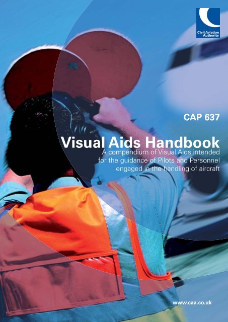
<strong>CAP</strong> <strong>637</strong><br />
<strong>Visual</strong> <strong>Aids</strong> <strong>Handbook</strong><br />
A compendium of <strong>Visual</strong> <strong>Aids</strong> intended<br />
for the guidance of Pilots and Personnel<br />
engaged in the handling of aircraft<br />
www.caa.co.uk
<strong>CAP</strong> <strong>637</strong><br />
<strong>Visual</strong> <strong>Aids</strong> <strong>Handbook</strong><br />
A compendium of <strong>Visual</strong> <strong>Aids</strong> intended<br />
for the guidance of Pilots and Personnel<br />
engaged in the handling of aircraft
© 2007 Civil Aviation Authority<br />
All rights reserved. Copies of this publication may be reproduced for personal use, or for use<br />
within a company or organisation, but may not otherwise be reproduced for publication.<br />
To use or reference CAA publications for any other purpose, for example within training material<br />
for students, please contact the CAA at the address below for formal agreement.<br />
ISBN-13 978 0 11790 844 4<br />
First issued January 1997<br />
Issue 2, May 2007<br />
Enquiries regarding the content of this publication should be addressed to:<br />
Aerodrome Standards Department, Safety Regulation Group, Civil Aviaiton Authority, Aviation<br />
House, Gatwick Airport South, West Sussex, RH6 0YR<br />
The latest version of this document is available in electronic format at www.caa.co.uk/publications,<br />
where you may also register for e-mail notifi cation of amendments.<br />
Published by TSO (The Stationery Offi ce) on behalf of the CAA.<br />
Printed copy available from:<br />
TSO, PO Box 29, Norwich NR3 1GN www.tso.co.uk<br />
Telephone orders/general enquries: 0870 600 5522 E-mail: book.orders@tso.co.uk<br />
Fax orders: 0870 600 5533 Textphone: 0870 240 3701
<strong>CAP</strong> <strong>637</strong> <strong>Visual</strong> <strong>Aids</strong> <strong>Handbook</strong><br />
Contents<br />
Foreword 1<br />
Chapter 1 Aeronautical Ground Lighting<br />
General 1<br />
Civil Aerodromes 1<br />
Government (Military) Aerodromes 1<br />
Colour and Intensity of Lights 1<br />
Aerodrome Beacon 2<br />
Approach Lighting 2<br />
Supplementary Approach Lighting 4<br />
Precision Approach Path Indicator (PAPI) 4<br />
Runway Lighting 5<br />
Taxiway Lighting 9<br />
Chapter 2 Surface Markings<br />
Chapter 3 Signs<br />
General 1<br />
Paved Surface Markings 1<br />
General 1<br />
Mandatory Signs 1<br />
Information Signs 4<br />
Chapter 4 <strong>Visual</strong> Docking Guidance Systems<br />
May 2007<br />
General 1<br />
Azimuth Guidance for Nose-in Stands (AGNIS) 1<br />
Aircraft Positioning and Information System (APIS/APIS++) 3<br />
Safegate Safedock 5<br />
Contents Page 1
<strong>CAP</strong> <strong>637</strong> <strong>Visual</strong> <strong>Aids</strong> <strong>Handbook</strong><br />
Chapter 5 Obstacle Lighting and Markings<br />
General 1<br />
Aerodrome Obstacles 1<br />
En-route Obstacles 2<br />
Chapter 6 Aerodrome Signals<br />
General 1<br />
Chapter 7 <strong>Visual</strong> <strong>Aids</strong> Specific to Helicopter Operations<br />
May 2007<br />
General 1<br />
Helicopter Approach Path Indicator (HAPI) 1<br />
Helicopter Aiming Point Marker 1<br />
Air Taxiway Markers 2<br />
Touch Down and Lift Off Area (TLOF) 2<br />
Final Approach and Take-Off Area (FATO) Designation Marking 3<br />
Elevated Heliports 3<br />
Offshore Helidecks 4<br />
Contents Page 2
<strong>CAP</strong> <strong>637</strong> <strong>Visual</strong> <strong>Aids</strong> <strong>Handbook</strong><br />
Foreword<br />
This document provides pilots and ground personnel engaged in the handling of aircraft with<br />
a general description of the purpose and meaning of visual aids that are typically displayed at<br />
aerodromes in the United Kingdom licensed by the Civil Aviation Authority. However, it is not<br />
intended to provide an assurance that the visual cues provided by a visual aid are correct or<br />
appropriate for a given flight operation.<br />
This document is not to be used to design or specify visuals aids for the purpose of aerodrome<br />
licensing. Licensing criteria, which include the technical specifications and display patterns of<br />
aeronautical ground visual aids, are contained in <strong>CAP</strong> 168, Licensing of Aerodromes.<br />
<strong>Visual</strong> aids provided at licensed aerodromes are notified in the UK Aeronautical Information<br />
Publication (AIP).<br />
Acknowledgements<br />
The CAA acknowledges the contribution of BAA, BALPA, SAFEGATE and FMT in the<br />
preparation of this document.<br />
May 2007<br />
Foreword Page 1
INTENTIONALLY LEFT BLANK
<strong>CAP</strong> <strong>637</strong> <strong>Visual</strong> <strong>Aids</strong> <strong>Handbook</strong><br />
Chapter 1 Aeronautical Ground Lighting<br />
1 General<br />
1.1 Aeronautical Ground Lighting (AGL) is the generic term used to describe the various<br />
lighting systems that are provided on an aerodrome for the guidance of pilots<br />
operating aircraft both at night and in low visibility conditions. AGL systems vary in<br />
complexity from the basic patterns found at small aerodromes in support of flying<br />
training operations, to the more advanced systems used in support of "all-weather<br />
operations", usually associated with an Instrument Landing System (ILS).<br />
1.2 The following paragraphs outline the AGL systems that have been accepted by the<br />
CAA as meeting both UK aerodrome licensing criteria and internationally agreed<br />
standards and recommended practices.<br />
2 Civil Aerodromes<br />
2.1 Details of AGL, where available at individual aerodromes, are notified in the UK AIP<br />
and on the appropriate Instrument Approach Charts. Where the AGL provided at a<br />
licensed aerodrome does not conform to the applicable specification in <strong>CAP</strong> 168, an<br />
appropriate aerodrome entry is included in the UK AIP or, if the deficiency is of a<br />
temporary nature, a Notice to Airmen (NOTAM) is issued detailing the AGL that is<br />
available.<br />
2.2 AGL at unlicensed aerodromes are neither inspected nor approved by the CAA, and<br />
may be of a non-standard pattern.<br />
3 Government (Military) Aerodromes<br />
3.1 AGL installed at Government aerodromes are not regulated or approved by the CAA,<br />
and may differ from those installed at civil aerodromes. The Ministry of Defence is<br />
now, however, applying civil standards for aerodrome design and facilities wherever<br />
practicable.<br />
4 Colour and Intensity of Lights<br />
4.1 Unless otherwise indicated, AGL systems emit a steady white<br />
light. High intensity<br />
AGL systems that are provided in support of low visibility operations normally have<br />
facility to independently control the luminance intensity of each element of the<br />
system. The intensities are set up, usually by the air navigation service provider, to<br />
suit local conditions. A pilot may ask for the intensity of an element(s) of the system<br />
to be adjusted if found to be inappropriate for the flight operation.<br />
4.2 The performance specification of high intensity lighting is defined by the need to<br />
provide guidance by day in low visibility conditions; the highest intensity settings are<br />
normally used in these conditions. Lower intensities are normally used by night.<br />
4.3 Low intensity systems are provided at those aerodromes at which operations are<br />
conducted at night but not in low visibility conditions; the luminance intensity of these<br />
systems is not normally adjustable.<br />
May 2007<br />
Chapter 1 Page 1
<strong>CAP</strong> <strong>637</strong> <strong>Visual</strong> <strong>Aids</strong> <strong>Handbook</strong><br />
5 Aerodrome Beacon<br />
5.1 An Aerodrome Beacon would normally be provided at those aerodromes that operate<br />
at night and where the level of background lighting, the surrounding terrain, the<br />
proximity of other aerodromes or the lack of navigation aids would make the<br />
aerodrome difficult to locate or to identify. There are two types of Aerodrome Beacon:<br />
the Identification Beacon and the Location Beacon.<br />
5.2 An Identification Beacon flashing a two letter identification code in green would<br />
normally be provided at an aerodrome where a number of aerodromes in the same<br />
vicinity operate at night and confusion could arise as to identity. Government<br />
aerodromes are normally equipped with a red identification beacon.<br />
5.3 A Location Beacon would normally be provided at an aerodrome that is situated well<br />
away from other aerodromes and where no confusion could exist as to identity. The<br />
signal produced by a Location Beacon is determined by the amount of background<br />
lighting as follows:<br />
a) Where the aerodrome is also situated well away from areas of high background<br />
lighting, the Location Beacon would display a white flashing light.<br />
b) Where the aerodrome is situated in an area where there is a high level of<br />
background lighting, such as in the vicinity of a city where a flashing white light<br />
would be difficult to see, the Location Beacon would display a green light flashing<br />
alternately with a white light.<br />
6 Approach Lighting<br />
6.1 A variety of approach lighting systems, based on the centre line and cross bar<br />
concept, are in use at aerodromes throughout the UK. These systems range from the<br />
simple low intensity centre line and cross bar - shown at Figure 1.1 - intended to serve<br />
visual runways at night only, to the more complex Calvert System comprising<br />
centreline and 5 cross bars - shown at Figure 1.3 and 1.4 - for day and night use on<br />
ILS equipped runways.<br />
6.2 Simple approach lighting systems normally commence 500 m prior to the runway<br />
threshold whilst the full Calvert System commences 900 m prior to runway threshold.<br />
Where, because of the geography of the approach, it is not possible to install a full<br />
system, a shortened system is employed and the Runway <strong>Visual</strong> Range (RVR) minima<br />
associated with the instrument approach procedure adjusted accordingly. Except<br />
where supplemented by red side barrettes as described below, approach lighting is<br />
white<br />
in colour.<br />
May 2007<br />
Chapter 1 Page 2
<strong>CAP</strong> <strong>637</strong> <strong>Visual</strong> <strong>Aids</strong> <strong>Handbook</strong><br />
May 2007<br />
Figure 1.1<br />
SIMPLE APPROACH AND<br />
RUNWAY LIGHTING SYSTEM<br />
APAPI<br />
Figure 1.2<br />
APPROACH AND RUNWAY LIGHTING<br />
TYPICAL CAT I SYSTEM SHOWING<br />
TAKE-OFF STARTER EXTENSION AND<br />
STOPWAY LIGHTING<br />
STOPWAY<br />
YELLOW<br />
CAUTION ZONE<br />
STARTER<br />
EXTENSION<br />
Figure 1.3<br />
APPROACH AND RUNWAY LIGHTING<br />
TYPICAL CAT II OR CAT III SYSTEM<br />
RUNWAY END<br />
TOUCHDOWN<br />
ZONE<br />
PAPI<br />
SUPPLEMENTARY<br />
APPROACH<br />
COLOUR CODED<br />
CENTRELINE<br />
CENTRELINE<br />
AND 5 BAR<br />
RUNWAY<br />
THRESHOLD<br />
AND WING<br />
BARS<br />
Chapter 1 Page 3
<strong>CAP</strong> <strong>637</strong> <strong>Visual</strong> <strong>Aids</strong> <strong>Handbook</strong><br />
7 Supplementary Approach Lighting<br />
7.1 At those aerodromes where Category II and III approaches are conducted,<br />
Supplementary Approach Lighting consisting of white centreline barrettes and two<br />
rows of red side barrettes, as shown at Figure 1.3, is installed in order to provide the<br />
pilot with enhanced visual cues over the last 300 m of the approach.<br />
NOTE: At certain aerodromes with displaced thresholds, the supplementary<br />
approach lighting is inset into the runway and in certain weather and ambient<br />
light conditions the centreline barrettes, at the higher intensity settings, can<br />
partially obscure the runway centreline lighting to pilots lining up for<br />
departure. Pilots experiencing problems of this nature should ask for the<br />
intensity of the supplementary lighting to be adjusted or extinguished.<br />
8 Precision Approach Path Indicator (PAPI)<br />
8.1 This visual aid provides approach slope guidance by use of red and white<br />
light<br />
signals which are interpreted as illustrated at Figure 1.4. The PAPI normally comprises<br />
a single row of 4 light units except that, on those runways that do not support jet<br />
public transport operations, an abbreviated 2 unit system (APAPI) may be used. The<br />
system is normally installed on the left side of the runway as seen from the approach.<br />
However, at some aerodromes, the units are located on the right side if it is<br />
impracticable to install on the left.<br />
8.2 At those aerodromes where aircraft with short take-off and landing (STOL)<br />
characteristics operate regularly, an additional separately selected PAPI, set at a<br />
steeper approach angle, may be provided. These STOL units are normally situated on<br />
the right side of the runway and operate only for STOL approaches.<br />
8.3 At Government aerodromes PAPI units may be provided on both sides of the runway.<br />
8.4 The PAPI signal is not designed to be used beyond 15° either side of the runway<br />
centreline. Any additional restrictions placed on the use of a particular installation will<br />
be notified under the 'Warnings' section of the appropriate aerodrome entry in the<br />
AIP.<br />
NOTE: Where obstacles located at the extremities of the visual signal preclude the<br />
provision of safe clearance, the appropriate aerodrome entry in the UK AIP<br />
will be annotated to that effect.<br />
8.5 The Minimum Eye Height over Threshold (MEHT), which is notified in AIP, is a<br />
reference value, calculated with respect to the promulgated approach angle for each<br />
PAPI. It is the lowest eye height over the runway threshold at which an on-slope<br />
indication will be seen. From examination of published MEHT, it may at first sight<br />
appear that for some runways, adequate wheel clearance at the threshold is not<br />
assured for all types of aircraft likely to use those runways. However, a typical eye<br />
height achieved in practice when crossing the threshold following well established<br />
'on slope' approach would in fact be well above the published MEHT value.<br />
May 2007<br />
Chapter 1 Page 4
<strong>CAP</strong> <strong>637</strong> <strong>Visual</strong> <strong>Aids</strong> <strong>Handbook</strong><br />
May 2007<br />
Figure 1.4 Typical PAPI System<br />
8.6 Where used together with ILS, PAPI is located so as to ensure, as far as is practicable,<br />
correlation between the two approach paths. However, such a siting is made on the<br />
assumption that the pilot's eye level is above the ILS glide path receiver aerial, as is<br />
the case with most commercial aircraft. Pilots of aircraft in which the ILS aerial is<br />
mounted above the level of the pilot's eye may see a PAPI indication 'slightly low'<br />
(see Figure 1.4 D) when on the ILS glide path.<br />
9 Runway Lighting<br />
A B<br />
TOO HIGH SLIGHTLY HIGH<br />
C<br />
ON CORRECT APPROACH PATH<br />
D E<br />
SLIGHTLY LOW TOO LOW<br />
9.1 All runways licensed for night use have Edge, Threshold and End Lighting. Centreline<br />
and Touchdown Zone Lighting is provided as additional guidance in support of low<br />
visibility operations.<br />
9.2 Runway Edge Lighting<br />
9.2.1 Runway Edge Lighting is located along the edges of the area declared for use as the<br />
runway delineated by white<br />
edge markings, and may be provided either by elevated<br />
or by flush fitting lamp fixtures. At some aerodromes where elevated runway edge<br />
lights are employed, the light fixtures may be located on the grass shoulder just<br />
beyond the declared runway width. Portable battery operated lights may be used in<br />
place of fixed lamp fittings at small aerodromes where limited operations take place<br />
at night.<br />
Chapter 1 Page 5
<strong>CAP</strong> <strong>637</strong> <strong>Visual</strong> <strong>Aids</strong> <strong>Handbook</strong><br />
9.2.2 Runway Edge Lighting is white except in the following instances:<br />
a) Caution Zone Lighting<br />
On ILS equipped runways without centreline lighting, yellow edge lighting as<br />
illustrated at Figure 1.2, is installed on the upwind 600 m or one third of the lighted<br />
runway length available, whichever is the less. The yellow 'caution zone' so<br />
formed gives a visual warning of the approaching runway end.<br />
b) Pre-Threshold Lighting<br />
Where a landing threshold is displaced, but the pre-threshold area is available for<br />
the take-off run, the lights between the beginning of the runway pavement and the<br />
displaced threshold show red from the approach, as illustrated at Figure 1.5. Pilots<br />
taking off in such a situation would see red edge lights up to the green threshold<br />
then white edge lights beyond. Where a starter extension, narrower than its<br />
associated runway is provided, blue edge lighting is normally used to mark the<br />
edges, as illustrated at Figure 1.5.<br />
c) Runway Exit Lighting<br />
One or two omni-directional blue lights may replace or supplement the edge lights<br />
in order to indicate an exit taxiway.<br />
d) Stopway Lighting<br />
Where stopway is provided at the end of a runway, the declared stopway is<br />
delineated by red edge and end lighting as illustrated in Figure 1.5 showing ONLY<br />
in the direction of landing. A stopway is provided for emergency use only and is<br />
not normally suitable for routine use.<br />
May 2007<br />
Chapter 1 Page 6
<strong>CAP</strong> <strong>637</strong> <strong>Visual</strong> <strong>Aids</strong> <strong>Handbook</strong><br />
May 2007<br />
Figure 1.5 Runway Edge, Threshold and Edge Lighting<br />
VIEW FROM FLIGHTDECK<br />
AIRCRAFT TAXYING OR<br />
LANDING IN DIRECTION<br />
SHOWN<br />
VIEW FROM FLIGHTDECK<br />
AIRCRAFT ON APPROACH OR<br />
LINED UP ON NARROW WIDTH<br />
STARTER EXTENSION<br />
STOPWAY<br />
FOR EMERGENCY<br />
OVER-RUN USE ONLY<br />
FULL WIDTH<br />
STARTER EXTENSION<br />
NOT AVAILABLE FOR<br />
LANDINGS<br />
THRESHOLD LIGHTS<br />
VIEW FROM FLIGHTDECK<br />
AIRCRAFT ON APPROACH OR<br />
LINED UP ON STARTER<br />
EXTENSION<br />
VIEW FROM FLIGHTDECK<br />
AIRCRAFT TAXYING OR<br />
LANDING IN DIRECTION<br />
SHOWN<br />
RUNWAY EDGE<br />
LIGHTING (WHITE)<br />
VISIBLE BOTH DIRECTIONS<br />
RUNWAY END LIGHTS<br />
NARROW WIDTH (BLUE)<br />
STARTER EXTENSION<br />
NOT AVAILABLE FOR<br />
LANDINGS<br />
9.3 Runway Threshold and Runway End Lighting<br />
9.3.1 Runway threshold lighting is green and indicates the start of the available landing<br />
distance. Green threshold wing-bars are provided at certain aerodromes where there<br />
is a need to accentuate the threshold. Patterns vary from the full threshold and wingbar<br />
lighting shown at Figures 1.2, 1.3, and 1.5 to abbreviated versions shown at<br />
Figures 1.1 and 1.5. Runway end lighting is red and marks the extremity of the<br />
runway that is available for manoeuvring. Pilots should not land before the green<br />
threshold lighting nor continue a landing roll or taxi beyond the red runway end lights.<br />
9.4 Runway Centreline Lighting<br />
9.4.1 High intensity centreline lighting is provided in addition to edge lighting on runways<br />
equipped for low visibility operations. The centreline lighting is colour coded in order<br />
to warn a pilot of the approaching end of the runway. White centreline lighting<br />
extends from the threshold to 900 m from the runway end, the following 600 m is lit<br />
with alternate white<br />
and red lights, and the final 300 m lit by red centreline lighting,<br />
as shown at Figure 1.3.<br />
Chapter 1 Page 7
<strong>CAP</strong> <strong>637</strong> <strong>Visual</strong> <strong>Aids</strong> <strong>Handbook</strong><br />
9.5 Touchdown Zone (TDZ) Lighting<br />
9.5.1 On runways equipped for Category II and III approaches, additional lighting consisting<br />
of two rows of white barrettes, as shown at Figure 1.3, is installed in order to<br />
provide textural cues in the touchdown area. The additional lighting extends from the<br />
threshold either for 900 m or to the midpoint of the runway, whichever is the lesser<br />
distance.<br />
NOTE: The length of the TDZ lighting (normally 900 m) determines the length of the<br />
Obstacle Free Zone (OFZ) established to protect CAT II and III approaches<br />
below decision height (DH) and in the event of a baulked landing (or goaround)<br />
after DH. A go-around initiated beyond the end of the TDZ lighting is<br />
unlikely to be contained within the OFZ.<br />
9.6 Rapid Exit Taxiway Indicator Lights<br />
9.6.1 Rapid exit taxiway indicator lights (RETILs) provide pilots with distance to go<br />
information to the nearest rapid exit taxiway on the runway, to enhance situational<br />
awareness in low visibility conditions and enable pilots to apply braking action for<br />
more efficient roll-out and runway exit speeds.<br />
9.6.2 RETILs consist of six yellow lights adjacent to the runway centreline and configured<br />
in a three/two/one pattern spaced 100 m apart; the single light is 100 m from the start<br />
of the turn for the rapid exit taxiway, see Figure 1.6.<br />
Figure 1.6 Rapid Exit Taxiway Indicator Lights<br />
May 2007<br />
Chapter 1 Page 8
<strong>CAP</strong> <strong>637</strong> <strong>Visual</strong> <strong>Aids</strong> <strong>Handbook</strong><br />
10 Taxiway Lighting<br />
10.1 At those aerodromes equipped for low visibility operations, taxiways are equipped<br />
with green centreline lighting, otherwise blue edge lighting is provided, as shown in<br />
Figure 1.7. Where green centreline lighting is provided, blue taxiway edge lighting<br />
may also be installed as additional guidance on sections of taxiway that are difficult to<br />
negotiate. Green taxiway centreline lighting may be provided on the runway prior to<br />
an exit taxiway in order to give lead-off guidance. However, see paragraph 10.5. The<br />
edge of aprons, turning and holding areas are normally marked by blue lighting.<br />
NOTE 1: Where centreline lighting is installed on a taxiway leading onto a runway,<br />
the taxiway lighting is curved onto the near side of the runway centreline<br />
and pilots should make an appropriate allowance for any loss of Runway<br />
Declared Distance incurred in following the 'lead-on' lighting whilst lining<br />
up for take-off.<br />
NOTE 2: Taxiway centrelines are intended to provide safe clearance between the<br />
largest aircraft that the taxiway is designed to accommodate and fixed<br />
objects such as buildings, aircraft stands etc, provided that the pilot of the<br />
taxiing aircraft keeps the 'Cockpit' of the aircraft on the centreline and that<br />
aircraft on stands are properly parked. Taxi Holding Positions are normally<br />
located so as to ensure clearance between an aircraft holding and any<br />
aircraft passing in front of the holding aircraft, provided that the holding<br />
aircraft is properly positioned behind the holding position. Clearance to<br />
the rear of any holding aircraft cannot be guaranteed. When following<br />
a taxiway route, pilots and persons towing aircraft are expected to keep a<br />
good lookout, consistent with the prevailing visibility and are responsible<br />
for taking all possible measures to avoid a collision with another aircraft or<br />
a vehicle.<br />
Figure 1.7 Taxiway Lighting<br />
May 2007<br />
CENTRELINE LIGHTING<br />
STOP BAR<br />
GUARD LIGHTS<br />
COLOUR CODED<br />
CENTRELINE<br />
20<br />
APRON EDGE<br />
LIGHTING<br />
HIGH SPEED EXIT<br />
TAXIWAYS COLOUR<br />
CODED<br />
TAXIWAY EDGE<br />
LIGHTING<br />
Chapter 1 Page 9
<strong>CAP</strong> <strong>637</strong> <strong>Visual</strong> <strong>Aids</strong> <strong>Handbook</strong><br />
10.2 Stop Bars and Lead-on Lights<br />
10.2.1 Lighted Stop Bars and Lead-on Lights are provided at those aerodromes authorised<br />
for low visibility operations. A Stop Bar consists of a row of lights spaced equally<br />
across the taxiway normally at right angles to the centreline and showing red towards<br />
an approaching aircraft when lit. Stop Bars are normally installed in association with<br />
green Lead-on Lights which form part of the taxiway centreline lighting beyond the<br />
Stop Bar. The Lead-on Lights are interlinked with the Stop Bar so that when the Stop<br />
Bar is 'on' the green centreline beyond the Stop Bar is 'off' and vice versa, as shown<br />
in Figure 1.8. In this way, the Stop Bar and associated Lead-on Lights act in the same<br />
sense as traffic lights; therefore pilots must not taxi an aircraft across a Stop Bar that<br />
is lit. Stop bars are provided at entrances to runways, e.g. runway holding positions,<br />
and may also be provided at taxiway intersections and at other locations.<br />
NOTE: At some aerodromes where, for example, a Stop Bar is located on or close<br />
to a bend in the taxiway route, additional elevated red lights may be installed<br />
outboard of each taxiway edge as shown at Figure 1.7, in order to provide<br />
maximum advanced warning of the Stop Bar location.<br />
Figure 1.8 Stop Bar and Lead-on Lights<br />
10.3 Runway Guard Lights<br />
10.3.1 Runway Guard Lights are pairs of alternately flashing yellow lights, one pair located<br />
on each side of the taxiway and provide a warning of the close proximity of the<br />
runway. Where the taxiway is wider than normal, an alternative form of Runway<br />
Guard Light may be provided comprising additional pairs of flashing yellow lights<br />
inset into and stretching across the full width of the taxiway. The electrical circuits are<br />
so arranged that alternate lights flash in unison. Runway Guard Lights, often referred<br />
to as "Wig Wags", are illustrated at Figure 1.9.<br />
Figure 1.9 Runway Guard Lights<br />
May 2007<br />
STOP BAR ON STOP BAR OFF<br />
Pattern A<br />
Pattern B<br />
Chapter 1 Page 10
<strong>CAP</strong> <strong>637</strong> <strong>Visual</strong> <strong>Aids</strong> <strong>Handbook</strong><br />
10.4 Taxiway Guidance System<br />
10.4.1 At aerodromes where Category II and III operations take place or where ground<br />
movement requirements are complex, a surface movement guidance and control<br />
system (SMGCS) may be installed in order to regulate traffic. The system operates by<br />
selective switching of the taxiway centreline lighting so that individual sections or<br />
routes, each terminating at a lit Stop Bar, are illuminated in order to show the way<br />
ahead. The Stop Bar is extinguished as the next section of taxiway centreline lighting<br />
is selected.<br />
10.5 Colour Coded Taxiway Centreline Lighting<br />
10.5.1 Where part of a taxiway equipped with centreline lighting lies within the ILS Sensitive<br />
Area or is sufficiently close to a runway that aircraft on that part of the taxiway would<br />
present an obstruction to aircraft landing or taking-off, that part of the taxiway will be<br />
identified by alternate green and yellow centreline lights, as shown at Figure 1.6 and<br />
1.7. Pilots should avoid stopping with any part of their aircraft in such areas.<br />
10.6 Taxiway Intersection Lights<br />
10.6.1 At some aerodromes where multiple intersecting taxiways are not provided with<br />
selective route guidance, Taxiway Intersection Lights may be provided. These consist<br />
of a row of at least 3 steady yellow lights disposed symmetrically about the taxiway<br />
centreline. Pilots approaching an intersection where these lights are displayed should<br />
give way to crossing traffic unless otherwise instructed by air traffic control (ATC).<br />
10.7 Reflective Taxiway Edge Markers and Centreline Studs<br />
10.7.1 On taxiways that are used infrequently, reflective edge markers or centreline studs<br />
may be used instead of taxiway lighting. Edge markers are blue and centreline studs<br />
are green.<br />
10.8 Unpaved Taxiway Routes<br />
10.8.1 Where taxiing is confined to specific routes on unpaved areas, the routes may either<br />
be edged with blue portable lights laid out as for normal taxiway edge lighting, or be<br />
provided with reflective taxiway edge markers. In certain circumstances, apron<br />
floodlighting may be accepted as sufficient illumination of adjacent taxiways. On<br />
grass aerodromes where specific taxiways are not provided, portable white lights<br />
may be used to mark the boundary of the manoeuvring area.<br />
May 2007<br />
Chapter 1 Page 11
INTENTIONALLY LEFT BLANK
<strong>CAP</strong> <strong>637</strong> <strong>Visual</strong> <strong>Aids</strong> <strong>Handbook</strong><br />
Chapter 2 Surface Markings<br />
1 General<br />
1.1 Surface Markings are provided on aerodromes in order to assist pilots in identifying<br />
certain locations and to provide guidance for ground movement by day. For the<br />
purposes of this document, Surface Markings have been divided into two groups,<br />
namely Paved Surface Markings and Unpaved Surface Markings.<br />
2 Paved Surface Markings<br />
2.1 Paved Surface Markings are normally produced by the application of skid resistant<br />
paints or thermo-plastic materials directly onto the pavement. The markings fall into<br />
three categories namely Paved Runway Markings, Paved Taxiway Markings and<br />
Paved Apron Markings, all of which are described in the following paragraphs.<br />
2.2 Paved Runway Markings<br />
2.2.1 Paved Runway Markings are white<br />
and those in use at aerodromes in UK are<br />
explained below. Illustrations of the various markings are given at Figure 2.1.<br />
a) Runway Designation Marking<br />
All paved runways are identified by a Runway Designation Marking. This marking<br />
consists of a two digit number indicating the magnetic heading of the runway to<br />
the nearest 10 degrees. At those aerodromes with parallel runways where the<br />
same magnetic heading applies to more than one runway, the Designation<br />
Marking will include a letter, such as 'L' identifying the left runway as seen from<br />
the approach, 'C' identifying the centre runway where there are 3 parallel runways<br />
or 'R' for the right runway, as appropriate.<br />
b) Threshold, Edge and Centreline Markings<br />
All paved runways have Centreline and Threshold Markings. The Threshold<br />
Markings differ according to the classification of the runway. Runway Edge<br />
Marking is normally provided on all ILS equipped runways and those other runways<br />
where there is insufficient contrast between the runway and its shoulders or<br />
where the declared runway width is less than the paved width.<br />
c) Displaced Threshold Markings<br />
While Threshold Markings are normally located at the beginning of the paved<br />
runway surface, they may be displaced along the runway where, for example,<br />
there are obstructions on the approach or where the first portion of the pavement<br />
is unfit for the movement of aircraft. Where displacement is of a temporary nature,<br />
e.g. to accommodate runway maintenance, the normal threshold markings will be<br />
obscured and the appropriate Displaced Threshold Marking and threshold marker<br />
boards, illustrated at Figure 2.1 (e), put in place in order to mark the new threshold.<br />
Whenever a threshold is displaced, the pre-threshold area will be marked<br />
according to its usability at Figure 2.1 (d) and (e).<br />
d) TDZ and Aiming Point Markings<br />
All ILS equipped runways and those other runways where the touchdown zone is<br />
insufficiently conspicuous are provided with TDZ and Aiming Point Markings as<br />
shown at Figure 2.1 (c). These markings are intended to give added visual cues to<br />
May 2007<br />
Chapter 2 Page 1
<strong>CAP</strong> <strong>637</strong> <strong>Visual</strong> <strong>Aids</strong> <strong>Handbook</strong><br />
May 2007<br />
the runway surface, particularly in conditions of poor visibility; they also indicate<br />
the optimum touchdown zone on the runway. The apparent distance between the<br />
Aiming Point Marking and the Runway Threshold Marking, as seen from the<br />
approach, is intended to aid pilots in judging their angle of approach.<br />
Figure 2.1 Paved Runway Markings (not to scale)<br />
a) <strong>Visual</strong> Runways - LDA < 1200m b) Non Precision Approach Runways, <strong>Visual</strong> Runways of LDA<br />
Centre Line Marking<br />
>1200m and where Threshold requires emphasis<br />
20<br />
Runway Designator<br />
c) Precision Approach Runways<br />
20<br />
20<br />
20<br />
Edge<br />
Marking<br />
d) Permanently Displaced Threshold<br />
Pre-Threshold Markings<br />
i) Pre-threshold area of runway<br />
fit for movement of aircraft<br />
and available as starter<br />
extension for take-off but not<br />
available for landing<br />
ii) Pre-threshold area of runway<br />
unfit for the movement of<br />
aircraft and unsuitable as<br />
stopway<br />
iii) Pre-threshold area of runway<br />
fit for use as a stopway by<br />
aircraft landing in the<br />
opposite direction but not fit<br />
for normal movement of<br />
aircraft<br />
20<br />
20<br />
Touchdown Zone Markings<br />
20<br />
20<br />
Threshold Marking<br />
20<br />
Aiming Point Mark Touchdown Zone Markings<br />
e) Temporarily Displaced Threshold<br />
and Pre-Threshold Markings<br />
New Theshold<br />
i) Pre-threshold area of runway fit for<br />
movement of aircraft and available as<br />
starter extension for take-off but not<br />
available for landing<br />
New Threshold<br />
See Table C<br />
ii) Pre-threshold area of runway<br />
unfit for movement of aircraft<br />
Chapter 2 Page 2
<strong>CAP</strong> <strong>637</strong> <strong>Visual</strong> <strong>Aids</strong> <strong>Handbook</strong><br />
2.3 Paved Taxiway markings<br />
2.3.1 Paved Taxiway Markings are yellow in colour and consist of Centreline, Runway Taxi-<br />
Holding Position, Intermediate Taxi-Holding Position, Edge and Information markings<br />
all of which are illustrated at Figure 2.2 and described below. The direction in which<br />
the holding instruction implicit in the Runway Taxi-Holding Position Pattern 'B' and<br />
Intermediate Taxi-Holding Position Markings applies, is determined by the<br />
accompanying sign described in Chapter 3 paragraph 2, i.e. the direction from which<br />
the sign face is visible indicates the direction in which the holding requirement<br />
applies.<br />
a) Centreline Marking<br />
The Taxiway Centreline Marking consists of a single continuous yellow line<br />
marking the centre of the taxiway. Where a taxiway crosses a runway, the Taxiway<br />
Centreline Marking will indicate the route to be followed but the marking is<br />
interrupted as necessary in order to accommodate the runway markings. Taxiway<br />
centrelines are located to provide safe clearance between the largest aircraft that<br />
the taxiway is designed to accommodate and fixed objects such as buildings,<br />
aircraft stands etc, provided that the pilot of the taxiing aircraft keeps the 'Cockpit'<br />
of the aircraft on the centreline and that aircraft on a stand are properly parked.<br />
NOTE 1:At runway-taxiway intersections, where the taxiway centreline is curved<br />
onto the nearside of the runway centreline, pilots should take account,<br />
where appropriate, of any loss of Runway Declared Distances incurred in<br />
following the ‘lead-on’ line lining up for take-off.<br />
May 2007<br />
NOTE 2:At major aerodromes in the UK, the taxiway width is determined to<br />
ensure a specified minimum clearance between the outer wheels of the<br />
largest aircraft that the taxiway is designed to accommodate and the<br />
taxiway edge. The minimum wheel to edge clearance is assured in turns<br />
provided that the pilot keeps the 'Cockpit' over the taxiway centreline.<br />
Chapter 2 Page 3
<strong>CAP</strong> <strong>637</strong> <strong>Visual</strong> <strong>Aids</strong> <strong>Handbook</strong><br />
May 2007<br />
Figure 2.2 Paved Taxiway Markings (not to scale)<br />
1<br />
2<br />
3<br />
4<br />
Runway Taxi-Holding Position marking pattern ‘A’ identifying<br />
the last holding position prior to entering runway. Marks<br />
visual/CAT I & CAT II/III Taxi-Holding Positions where only<br />
one Taxi-Holding Position is provided.<br />
Runway Taxi-Holding Position marking pattern ‘B’ identifying<br />
Category I, II or III where a closer visual/CAT I Taxi-Holding<br />
Position is provided.<br />
Intermediate Taxi-Holding Position<br />
markings.<br />
Taxiway edge marking indicates paved shoulder<br />
of bearing strength less than Taxiway or area<br />
beyond mark not intended for aircraft use.<br />
A<br />
B<br />
Surface painted<br />
location marking<br />
Surface<br />
painted<br />
direction<br />
marking<br />
A<br />
b) Runway Taxi-Holding Position (RTHP) Marking<br />
RTHPs are established on each taxiway leading to a runway in order to protect<br />
aircraft on take-off and landing by ensuring that other taxiing aircraft and vehicles<br />
are held well clear of the runway and, where appropriate, outside the ILS Sensitive<br />
Area. There are two styles of RTHP marking, patterns A and B, both of which are<br />
illustrated at Figure 2.2.<br />
i) A Pattern 'A' style RTHP marking consists of two solid and two broken lines laid<br />
across the entire width of the taxiway and normally at right angles to the<br />
taxiway centreline, the broken lines being closer to the runway (see<br />
enlargement 1 Figure 2.2).<br />
ii) A Pattern 'B' style RTHP marking, consists of a ladder mark laid across the<br />
entire width of the taxiway and normally at right angles to the taxiway centreline<br />
(see enlargement 2 Figure 2.2).<br />
The last RTHP on a taxiway prior to entering the runway is always marked by a<br />
Pattern 'A' RTHP marking; other RTHPs, where established on the same taxiway,<br />
are marked by a Pattern 'B' style marking. RTHP markings are supported by the<br />
appropriate RTHP sign as described at Chapter 3 paragraph 2.<br />
Taxi Holding Positions are normally located so as to ensure clearance between an<br />
aircraft holding and any aircraft passing in front of the holding aircraft, provided<br />
that the holding aircraft is properly positioned behind the holding position.<br />
Clearance to the rear of any holding aircraft cannot be guaranteed. When<br />
3<br />
Taxiway<br />
centreline<br />
marking<br />
1<br />
2<br />
1<br />
Chapter 2 Page 4
<strong>CAP</strong> <strong>637</strong> <strong>Visual</strong> <strong>Aids</strong> <strong>Handbook</strong><br />
following a taxiway route, pilots and persons towing an aircraft are expected to<br />
keep a good lookout and are responsible for taking all possible measures to avoid<br />
collisions with other aircraft and vehicles.<br />
NOTE 1:Upon reaching a Taxi Holding Position identifying a taxi clearance limit, the<br />
pilot should stop the aircraft as close as possible to the Taxi-Hold Position<br />
Marking, whilst ensuring that no part of the aircraft protrudes beyond the<br />
marking.<br />
NOTE 2:At those aerodromes where an ATC unit is established, pilots must not<br />
taxi beyond a Taxi-Holding Position marking towards a runway without<br />
ATC clearance. Where there is no ATC unit, the Pattern 'A' RTHP marking<br />
is used to indicate the position where aircraft and vehicles are required to<br />
hold whilst giving way to aircraft using, or on approach to, the runway.<br />
c) Intermediate Taxi-Holding Position (ITHP) Marking<br />
At those aerodromes where the taxiway layout is complex or involves multiple<br />
intersecting taxiways, ITHPs may be established in order to protect a priority<br />
taxiway route. These holding positions are marked by a single broken line laid<br />
across the entire width of the taxiway and normally at right angles to the taxiway<br />
centreline as illustrated in Figure 2.2 enlargement 3. An ITHP marking is supported<br />
by a sign as described at Chapter 3 paragraph 2.5. These markings are located so<br />
as to provide clearance from aircraft passing in front of the holding aircraft.<br />
d) Taxiway Edge Marking<br />
Edge markings as illustrated at Figure 2.2 enlargement 4, are used where the area<br />
beyond the taxiway edge is paved but not normally available for use by aircraft.<br />
e) Information Markings<br />
Information Markings, in the form of surface painted directions, may be provided<br />
where the use of a sign might cause an unacceptable obstruction or to assist in the<br />
prevention of runway incursions. Examples of Information Markings are shown at<br />
Figure 2.2.<br />
2.4 Apron Markings<br />
2.4.1 Apron markings intended for pilot use are yellow in colour. Where a marking is<br />
provided for the guidance of pilots parking aircraft on stands, this normally comprises<br />
just a stand centreline marking.<br />
2.4.2 Stands Provided with <strong>Visual</strong> Docking Guidance<br />
2.4.2.1 At those airports where visual docking guidance is provided, a variety of different<br />
stand layout markings are used. An example of the layout and markings used at some<br />
airports in the UK is illustrated at Figure 2.3. <strong>Visual</strong> Docking Guidance Systems (VDGS)<br />
are described at Chapter 4.<br />
May 2007<br />
Chapter 2 Page 5
<strong>CAP</strong> <strong>637</strong> <strong>Visual</strong> <strong>Aids</strong> <strong>Handbook</strong><br />
May 2007<br />
Figure 2.3 Typical Stand Layout and Markings<br />
Chapter 2 Page 6
<strong>CAP</strong> <strong>637</strong> <strong>Visual</strong> <strong>Aids</strong> <strong>Handbook</strong><br />
Figure 2.4 Self Manoeuvring Stand Markings<br />
2.4.3 Self-manoeuvring Stand Markings<br />
2.4.3.1 Self-manoeuvring stand markings are provided to assist pilots in taxiing their aircraft<br />
to the correct parking position without the assistance either of a marshaller or a<br />
VDGS. A variety of different styles of marking are in use throughout the UK. An<br />
example of one style is at Figure 2.4; the method of use is described below:<br />
a) The pilot turns off the apron taxiway at the arrow which bears the allocated stand<br />
number and follows the lead-in line keeping the nosewheel on the centreline;<br />
b) When the FULL TURN arrow is directly abeam the first pilot's position, a turn,<br />
using the maximum nose wheel steering angle appropriate to the type of aircraft,<br />
is initiated in the direction indicated. This turn is continued until the longitudinal axis<br />
of the aircraft is parallel with the alignment bars seen ahead of the aircraftaircraft<br />
as the designed parking angle is reached;<br />
c) When the aircraft is parallel to the alignment bars, the turn is discontinued and the<br />
aircraft permitted to roll forward a distance of not more than 3 m in order to<br />
straighten the nose wheel. The aircraft is then stopped;<br />
d) When cleared to taxi by ATC, the pilot taxies off the stand in the direction indicated<br />
by the curved lead-off arrow disregarding the alignment bars.<br />
NOTE:The provision of safe clearances from other aircraft and fixed obstacles<br />
relies heavily on the accuracy with which the pilot follows the surface<br />
markings; turning too late, using too great a radius of turn or taxiing the<br />
aircraft too far forward, may reduce the clearances below the safe limit.<br />
Unlike the principle used on taxiways (cockpit on centreline), when<br />
manoeuvring onto stands the pilot must keep the nosewheel on the stand<br />
centreline. If in doubt the aircraft commander should seek assistance<br />
from a marshaller.<br />
May 2007<br />
FULL<br />
TURN<br />
TERMINAL<br />
BUILDING<br />
10 10<br />
APRON TAXIWAY CENTRELINE<br />
FULL<br />
TURN<br />
ALIGNMENT BARS<br />
11 11<br />
Chapter 2 Page 7
<strong>CAP</strong> <strong>637</strong> <strong>Visual</strong> <strong>Aids</strong> <strong>Handbook</strong><br />
2.4.4 Parking Spots and Parking Circles<br />
2.4.4.1 At some small aerodromes where aircraft parking space is at a premium, a yellow<br />
spot, number or circle may be painted on the apron indicating an individual aircraft<br />
parking position. Pilots should be aware that parking on the spot or within the circle<br />
does not guarantee safe separation either from fixed obstacles or from adjacent<br />
aircraft.<br />
2.4.5 Additional Apron Markings NOT for Pilot use<br />
2.4.5.1 White markings on an apron are intended for the guidance, control and movement<br />
of ground service vehicles. White hatched diagonal markings adjacent to an aircraft<br />
parking stand delineate an area that ground service vehicles should not park or stop<br />
in at any time.<br />
2.4.5.2 Some aprons may also provide additional markings to highlight safe routes for<br />
pedestrian access to an aircraft stand or the terminal building, typically these are<br />
green with a white inset border (with a Pedestrian symbol inside the border).<br />
2.4.5.3 Vehicle and equipment storage bays are typically depicted by a red box inset by a<br />
white border.<br />
NOTE: Enhanced hatched markings in clearways or other areas are used to denote<br />
where vehicles are not permitted to stop.<br />
3 Unpaved Surface Markings<br />
3.1 Unpaved surface markings are normally confined to runways and consist of Runway<br />
Edge, Centreline, Threshold and End Markings.<br />
3.1.1 Runway Edge and Centreline Marking<br />
3.1.1.1 The edges of runways are delineated by markers placed at regular intervals along the<br />
declared edges of the runway. Where provided, a centreline marking consists of<br />
rectangular markers inset flush with the runway surface and spaced at regular<br />
intervals along the declared runway centreline. Edge and centreline markers are<br />
normally white but may be of any single colour that best contrasts with the<br />
background.<br />
3.1.2 Runway Threshold and End Marking<br />
3.1.2.1 The Threshold and End of a runway are provided with markers of a similar type, size<br />
and colour as the edge markers. These markers are placed along the threshold and<br />
end of the runway and so positioned in relation to the edge markers as to form an 'L'<br />
shaped mark at each corner of the runway. In addition, each threshold is marked with<br />
a two character designator showing the magnetic heading of the runway to the<br />
nearest whole 10 degrees.<br />
May 2007<br />
Chapter 2 Page 8
<strong>CAP</strong> <strong>637</strong> <strong>Visual</strong> <strong>Aids</strong> <strong>Handbook</strong><br />
Chapter 3 Signs<br />
1 General<br />
1.1 The signs located on an aerodrome when used in conjunction with an aerodrome<br />
chart are intended to simplify surface movement guidance and control procedures,<br />
particularly in conditions of low visibility. Signs are divided into two categories, namely<br />
Mandatory Signs and Information Signs.<br />
2 Mandatory Signs<br />
2.1 Mandatory Signs consist of Runway Taxi-Holding Position (RTHP) signs, Intermediate<br />
Taxi-Holding Position (ITHP) signs and No Entry signs and display white<br />
characters<br />
on a red background as illustrated at Figure 3.1 and 3.2. RTHP and ITHP signs are<br />
located alongside the appropriate surface marking described in Chapter 2 paragraph<br />
2.3 and identify the holding position as well as indicate the direction in which the<br />
holding instruction applies. Pilots should not proceed beyond a Mandatory Sign<br />
unless directed to do so by ATC.<br />
2.2 Where there is more than one taxiway serving a runway or more than one RTHP on<br />
a taxiway, a Location Sign is normally attached to the RTHP sign in order to assist in<br />
identifying the position as illustrated at Figure 3.2.<br />
2.3 RTHP Sign for <strong>Visual</strong> and Category I Operations<br />
2.3.1 Where an aerodrome is equipped for operations up to and including ILS Category I<br />
approaches, an RTHP sign displaying the runway designator is located on both sides<br />
of the taxiway as illustrated at Figure 3.2 (a). However, at smaller aerodromes<br />
supporting only visual operations, the sign may be located on one side only (normally<br />
the left side) of the taxiway. Where there is no ATC unit, the RTHP sign identifies the<br />
position where aircraft and vehicles are required to hold whilst conceding right of way<br />
to aircraft using or on approach to the runway.<br />
May 2007<br />
Chapter 3 Page 1
<strong>CAP</strong> <strong>637</strong> <strong>Visual</strong> <strong>Aids</strong> <strong>Handbook</strong><br />
May 2007<br />
Figure 3.1 Example of Mandatory Signs for Aircraft Surface Movements<br />
a) <strong>Visual</strong> Runway Taxi-holding position - denotes the visual<br />
Taxi-Holding Position and also the ILS Cat I Holding Position where<br />
the <strong>Visual</strong> and CAT I Holding Positions are co-located.<br />
b) CAT I Runway Taxi-Holding Position Sign - denotes ILS CAT II<br />
Taxi-Holding Position - a <strong>Visual</strong>/CAT I Taxi-Holding Position may be<br />
established closer to the runway where it is necessary to expedite<br />
traffic flow.<br />
c) CAT II Runway Taxi-Holding Position Sign - marks the ILS CAT II<br />
Taxi-Holding Position - a <strong>Visual</strong>/CAT I Taxi-Holding Position may be<br />
established closer to the runway where it is necessary to expedite<br />
traffic flow.<br />
d) CAT II Runway Taxi-Holding Position Sign - marks the ILS CAT III<br />
Taxi-Holding Position - a CAT II Taxi-Holding Position and a <strong>Visual</strong>/CAT<br />
I Taxi-Holding Position may be established closer to the runway<br />
where it is necessary to expedite traffic flow.<br />
e) Combined Taxi-Holding Position Sign - marks the Taxi-Holding<br />
Position where the ILS - Taxi-Holding Positions are co-incident are<br />
co-incident. A <strong>Visual</strong> or CAT I Taxi-Holding Position Sign may be<br />
established or closer to the runway where it is necessary to expedite<br />
traffic flow.<br />
f) Intermediate Taxi-Holding Position Sign - marks a Holding<br />
Position established to protect a priority route.<br />
g) No Entry Sign<br />
Note: 1: The signs at (i) are used where the taxiway normally serves only one<br />
runway direction. The signs at (ii) are used where the taxiway normally serves both runway<br />
directions.<br />
2: Where a runway Taxi-Holding Position serves more than one runway, the sign layout at<br />
Figure 3.5 is used.<br />
(i)<br />
(ii)<br />
(i)<br />
(ii)<br />
(i)<br />
(ii)<br />
(i)<br />
(ii)<br />
(i)<br />
(ii)<br />
Chapter 3 Page 2
<strong>CAP</strong> <strong>637</strong> <strong>Visual</strong> <strong>Aids</strong> <strong>Handbook</strong><br />
May 2007<br />
Figure 3.2 Typical Runway Taxi-Holding Position Signs and<br />
Associated Taxiway Markings<br />
27<br />
27 II<br />
27 D 09-27 09-27 D<br />
A 27 CAT II 27 CAT II A D 09-27 CAT II 09-27 CAT II D<br />
27<br />
A1 27 27 A1<br />
A2 27 CAT II/III<br />
27 CAT II/III A2 A2 27 CAT III 27 CAT III<br />
27<br />
A1 27 27 A1<br />
A2 27 CAT I 27 CAT I A2<br />
09<br />
a) (a) (b) b)<br />
27<br />
09<br />
(c) (d)<br />
The diagrams in Figure 3.2 illustrate typical signs associated with various Runway<br />
Taxi-holding positions on Taxiway ‘A’ leading to the threshold of Runway 27 and on<br />
Taxiway ‘D’ leading to an intermediate taxiway entrance to Runway 09-27.<br />
NOTE: The signs at intermediate taxiway entrances as shown at Figure 3.2 (b) and<br />
(d) show the runway designation in both directions; a left turn is required to<br />
reach the threshold of Runway 09 and a right turn to reach the threshild of<br />
Runway 27.<br />
A1 27<br />
27 A1<br />
A1 27 CAT II 27 CAT II A1<br />
A2 27 CAT III<br />
27<br />
(e) (f )<br />
(g)<br />
27<br />
(h)<br />
27 27<br />
A2<br />
27 CAT III A2<br />
Chapter 3 Page 3
<strong>CAP</strong> <strong>637</strong> <strong>Visual</strong> <strong>Aids</strong> <strong>Handbook</strong><br />
2.4 Runway Taxi-Holding Position Sign for Category ll and lll Operations<br />
2.4.1 At aerodromes equipped for Category II and III ILS approaches, RTHP signs are<br />
annotated CAT II, CAT III or CAT II/III as appropriate, in the manner illustrated in<br />
Figures 3.1 and 3.2. However, because of the need to provide greater protection to<br />
Category II and III ILS systems, the RTHPs associated with these procedures are set<br />
farther back from the runway than those associated with visual or Category I<br />
operations; where this distance is such that it would hinder the expeditious flow of<br />
traffic when Category II or III procedures are not in force, a visual RTHP may be<br />
established in addition, closer to the runway, in the manner illustrated at Figure 3.2<br />
(e) and (f). Exceptionally, CAT I RTHPs may be established in this manner, as<br />
illustrated at Figure 3.1 (b), for the same reason.<br />
2.5 Intermediate Taxi-holding Position<br />
2.5.1 The style of sign illustrated at Figure 3.1 (f) is used to identify those locations where<br />
ITHPs have been established in order to protect a priority route. The signs display the<br />
taxiway designator accompanied by a number identifying the individual holding<br />
position.<br />
2.6 No Entry<br />
2.6.1 Where part of an aerodrome is restricted to one way traffic or is withdrawn from use,<br />
No Entry Signs, as illustrated at Figure 3.1 (g), are located on both sides of the mouth<br />
of the area showing the direction from which entry is prohibited.<br />
3 Information Signs<br />
3.1 Information Signs consist of Location, Direction and Destination Signs; they are<br />
provided only where there is an operational need to provide additional guidance to<br />
pilots manoeuvring on the ground, and should be used in conjunction with an<br />
aerodrome chart.<br />
3.2 Location Signs<br />
3.2.1 Location Signs are used to identify taxiways and where necessary, runways, such as<br />
at complicated intersections. Taxiways are normally designated by a single letter of<br />
the alphabet, e.g. 'A' for taxiway Alpha, 'B' for Bravo etc. The letters 'O', 'I' and 'X'<br />
are not used. On larger aerodromes, where there are more taxiways than letters of<br />
the alphabet, double letter designators may be used in order to identify minor<br />
taxiways or taxiway stubs. Runway Location Signs use the first two numbers of the<br />
runway magnetic heading.<br />
3.2.2 A Location Sign consists of the characters identifying the runway or taxiway in yellow<br />
lettering on a black background surrounded by a yellow border, as illustrated in<br />
Figure 3.3 (a) and (b). Where there is a need to identify a specific position on a taxiway,<br />
a Location Sign, displaying the taxiway designator accompanied by an identifying<br />
number as illustrated at Figure 3.3 (a) (ii), is used.<br />
3.3 Direction and Destination Signs<br />
3.3.1 Direction and Destination Signs consist of a route or destination label accompanied<br />
by an arrow pointing in the appropriate direction, displayed in black characters on a<br />
yellow background as illustrated at Figure 3.3. Direction Signs are normally<br />
accompanied by a Location Sign and positioned on the left side of a taxiway before<br />
an intersection, as shown at Figure 3.4, or adjacent to a runway, as shown at Figure<br />
3.5.<br />
May 2007<br />
Chapter 3 Page 4
<strong>CAP</strong> <strong>637</strong> <strong>Visual</strong> <strong>Aids</strong> <strong>Handbook</strong><br />
May 2007<br />
Figure 3.3 Examples of Information Signs (not to scale)<br />
(i)<br />
Designation<br />
(a) Taxiway Location Signs<br />
(b) Runway Location Sign<br />
09<br />
(ii)<br />
Specific Location<br />
Note the use of a hyphen to seperate reciprocal designators<br />
and the use of a dot to seperate other designators<br />
(e) Destination Sign to Different Runways<br />
STANDS<br />
1-5<br />
(g) Stand Destination Sign<br />
(iii)<br />
Taxiway Ending<br />
(c) Direction Sign (d) Runway Destination Sign<br />
(f) Inbound Destination Sign<br />
Chapter 3 Page 5
<strong>CAP</strong> <strong>637</strong> <strong>Visual</strong> <strong>Aids</strong> <strong>Handbook</strong><br />
May 2007<br />
Figure 3.4 Examples of Taxi Guidance Signs at Taxiway Intersections (not to scale)<br />
E<br />
(a) Standard 4 – Way Intersection<br />
F<br />
(c) Straight ahead Taxiway has<br />
changed designation<br />
(e) Location signs indicating<br />
exit from intersection<br />
Straight ahead Taxiway<br />
E E<br />
E<br />
A<br />
A A<br />
E E<br />
A A<br />
F<br />
A<br />
A<br />
E<br />
Straight ahead Taxiway<br />
E<br />
(b) Straight ahead Taxiway has<br />
direction change greater than 25 degrees<br />
F<br />
A<br />
(d) Y configuration with Taxiway 'A'<br />
changing direction<br />
(f) Taxiway ending sign<br />
A<br />
A<br />
E E<br />
Chapter 3 Page 6
<strong>CAP</strong> <strong>637</strong> <strong>Visual</strong> <strong>Aids</strong> <strong>Handbook</strong><br />
May 2007<br />
Figure 3.5 Examples of use of Runway Location Signs and Signs at<br />
Runway Taxi-Holding Positions Serving more than one Runway<br />
1<br />
09-27 13-31<br />
13<br />
09<br />
27<br />
31<br />
a) Taxiway entrance at intersection of two runways<br />
A<br />
27<br />
31<br />
B1<br />
31<br />
27<br />
27 31<br />
b) Taxiway entrance at intersection of two runway ends<br />
13<br />
60<br />
27<br />
31<br />
Note: 1 Taxi-holding position<br />
signs installed at<br />
intersections such as<br />
those illustrated<br />
here are handled in<br />
the manner shown.<br />
2 Runway location<br />
signs for runways 31<br />
and 13 are shown in<br />
this example on the<br />
right side of the<br />
runway in order to<br />
avoid confusion.<br />
Chapter 3 Page 7
INTENTIONALLY LEFT BLANK
<strong>CAP</strong> <strong>637</strong> <strong>Visual</strong> <strong>Aids</strong> <strong>Handbook</strong><br />
Chapter 4 <strong>Visual</strong> Docking Guidance Systems<br />
1 General<br />
1.1 <strong>Visual</strong> Docking Guidance Systems (VDGS), sometimes referred to as Nose-in Docking<br />
Guidance Systems or Stand Entry Guidance Systems (SEG), provide guidance where<br />
accurate aircraft parking is required. This is usually the case where airbridges are<br />
used. Those VDGS currently in use in the UK include Azimuth Guidance for Nose-in<br />
Stands (AGNIS), supported by Parallax Aircraft Parking Aid (PAPA). In some cases,<br />
mirrors may be provided to permit a pilot to view the position of the nosewheel of the<br />
aircraft relative to the stopping position.<br />
1.2 At major aerodromes Advanced <strong>Visual</strong> Docking Guidance Systems (AVDGS) are<br />
installed that provide electronically displayed information, such as the azimuth<br />
position of the aircraft and stopping distance. In some cases, the AVDGS determines<br />
the aircraft type automatically and sets the relevant guidance parameters accordingly.<br />
These systems are described in detail below.<br />
NOTE 1:A pilot should not assume that a stand is safe to enter simply because the<br />
stand (A)VDGS is active or lit. Where ground handling personnel are not<br />
present on the stand or if the pilot has any doubt about the position of any<br />
equipment on or NEAR to the stand, the aircraft should be stopped<br />
immediately and assistance requested.<br />
NOTE 2:Except under the guidance of a marshaller, an aircraft should not be taxied<br />
onto a (A)VDGS equipped stand when the guidance system is switched off<br />
or appears inactive.<br />
NOTE 3:Ground staff should NOT activate a (A)VDGS until a thorough inspection of<br />
the stand and its immediate surrounds has been made in order to ensure that<br />
all equipment is correctly parked in allocated areas and that the stand is safe<br />
for use by the type of aircraft assigned.<br />
2 Azimuth Guidance for Nose-in Stands (AGNIS)<br />
2.1 AGNIS provides Stand centreline alignment guidance and is normally used in<br />
conjunction with PAPA, marker boards, lines or mirrors, which provide stopping<br />
guidance separately. The system is designed for use from the left pilot position only<br />
and the unit displays two closely spaced vertical light bars mounted in a box, as<br />
illustrated at Figure 4.1, at about flight deck height ahead of the pilot. The light bars<br />
display one of the following signals:<br />
a) one red bar and one green bar as illustrated at Figure 4.1 (i) and (iii), indicating that<br />
the pilot should steer away from the red towards the green bar, or<br />
b) two green bars, indicating correct alignment, as illustrated at Figure 4.1 (ii).<br />
May 2007<br />
Chapter 4 Page 1
<strong>CAP</strong> <strong>637</strong> <strong>Visual</strong> <strong>Aids</strong> <strong>Handbook</strong><br />
Figure 4.1 AGNIS<br />
2.2 AGNIS may be supported by one of the following aids:<br />
a) PAPA<br />
This aid is normally positioned to the right side of the Stand centreline and provides<br />
stopping guidance by employing a black board marked with white vertical lines<br />
bearing aircraft type identification labels and in which a horizontal slot has been cut,<br />
as illustrated at Figure 4.2 (i). A short distance behind the slot is a verticallymounted<br />
white fluorescent light tube which, when aligned with the required<br />
aircraft type line, indicates the stop-point, as shown at Figure 4.2 (ii). An alternative<br />
layout is illustrated at Figure 4.2 (iii) where the board is not provided with a slot and<br />
the tube is mounted in front of it; the method of use is identical.<br />
Figure 4.2 PAPA<br />
May 2007<br />
L1011<br />
SLOT<br />
B757<br />
B747<br />
(i)<br />
(ii)<br />
Fluorescent Tube<br />
B747 1.11<br />
(iii)<br />
(iii)<br />
B747<br />
White Line<br />
Fluorescent Tube<br />
SLOT<br />
Chapter 4 Page 2
<strong>CAP</strong> <strong>637</strong> <strong>Visual</strong> <strong>Aids</strong> <strong>Handbook</strong><br />
b) Mirror<br />
The Mirror system consists of a mirror mounted to the left of the stand centreline<br />
and facing the approaching aircraft. The mirror is angled so that the pilot in the left<br />
hand seat can see the reflection of the aircraft nose wheel during the last few<br />
metres of the parking manoeuvre.<br />
The correct stopping position is indicated by aircraft type designators painted in<br />
mirror image on the apron surface. As the aircraft approaches, the pilot is able to<br />
see in the mirror a reflection of the aircraft nose wheel and an appropriate<br />
designator where the aircraft should be stopped. A yellow javelin headed arrow<br />
may be used as the designator, with the aircraft type given.<br />
3 Aircraft Positioning and Information System (APIS/APIS++)<br />
3.1 APIS/APIS++ is designed for use from the left pilot position and combines both<br />
alignment and stopping signals in one visual display mounted at flight deck height<br />
ahead of the pilot. The elements of the display as illustrated at Figure 4.3 are as<br />
follows:<br />
a) An alphanumeric yellow dot matrix element displayed in the upper portion of the<br />
unit indicating as appropriate, any of the signals illustrated.<br />
b) A yellow dot matrix progress strip element displayed on the lower left side of the<br />
unit indicating progress of the aircraft over the last 16.2 m of the approach to the<br />
stop position.<br />
c) An azimuth guidance element employing a moiré pattern.<br />
3.2 Prior to entering the stand the pilot must ensure that the following signals are<br />
displayed:<br />
a) Correct aircraft type<br />
b) Correct stand number<br />
3.3 The Azimuth Guidance element consists of a yellow moiré pattern signal providing<br />
directional guidance to the pilot in relation to the stand centreline as illustrated in<br />
Figure 4.3.<br />
May 2007<br />
Chapter 4 Page 3
<strong>CAP</strong> <strong>637</strong> <strong>Visual</strong> <strong>Aids</strong> <strong>Handbook</strong><br />
Aircraft<br />
type/series<br />
(solid from 20m<br />
before STOP)<br />
Figure 4.3 APIS++<br />
Door No.<br />
(if applicable)<br />
Flight<br />
number<br />
(if applicable / until<br />
30 from STOP)<br />
Stand<br />
number<br />
Text row<br />
(if applicable / until<br />
30 from STOP) Azimuth Guidance<br />
Aircraft<br />
stopped at<br />
stop position<br />
May 2007<br />
Aircraft is<br />
too far<br />
Steer Right<br />
(Captain)<br />
On Centerline<br />
Steer Left<br />
Closing Rate<br />
FMT APIS++ (Aircraft Parking and Information System)<br />
Azimuth and stopping guidance are provided from a display unit mounted at the<br />
extension of the stand centerline.<br />
Abort docking if display shows STOP or wrong aircraft type/series, or if the<br />
azimuth guidance display is not activated.<br />
Chapter 4 Page 4
<strong>CAP</strong> <strong>637</strong> <strong>Visual</strong> <strong>Aids</strong> <strong>Handbook</strong><br />
4 Safegate Safedock<br />
4.1 The Safegate Docking Guidance System (known as Safedock) is an AVDGS that<br />
provides azimuth guidance, distance to stop information, aircraft type and door in use<br />
guidance on a single electronic display, as illustrated at Figure 4.4.<br />
Figure 4.4 Safedock Guidance System<br />
May 2007<br />
Chapter 4 Page 5
INTENTIONALLY LEFT BLANK
<strong>CAP</strong> <strong>637</strong> <strong>Visual</strong> <strong>Aids</strong> <strong>Handbook</strong><br />
Chapter 5 Obstacle Lighting and Markings<br />
1 General<br />
1.1 Obstacles to air navigation are divided into two groups, namely Aerodrome Obstacles<br />
and En-route Obstacles. The following paragraphs outline the methods of marking<br />
and lighting obstacles in order that they may be readily identified.<br />
2 Aerodrome Obstacles<br />
2.1 An aerodrome obstacle is one that is located on an area intended for the surface<br />
movement of an aircraft or that extends above a defined surface intended to protect<br />
aircraft in flight or exceeds 150 m height above ground, within a radius of up to 15 km<br />
of the aerodrome. Significant aerodrome obstacles are listed in the AD section of the<br />
UK AIP and are shown on Instrument Approach and Landing Charts.<br />
2.2 All objects that are considered to be obstacles to aircraft in flight or manoeuvring on<br />
the ground are normally lit at night and, where the obstacle is insufficiently<br />
conspicuous by day, marked in contrasting colours. Surface obstructions and areas of<br />
bad ground on aerodrome movement areas are marked by the use of coloured<br />
markers or flags. The methods of marking and lighting of aerodrome obstacles are<br />
illustrated at Figures 5.1 and 5.2. Bad ground markers are illustrated in Chapter 6<br />
Table C of this document.<br />
2.3 Lighting<br />
2.3.1 Fixed obstacles of 45 m or less in height, width and length are normally lit by a single<br />
steady red light placed at the highest practicable point; those obstacles of greater size<br />
are normally provided with additional red lights in order to outline the extent of the<br />
obstruction as shown in Figure 5.1. Surface obstructions and unserviceable parts of<br />
the movement area are normally delineated by portable red lights. Mobile obstacles<br />
such as vehicles and equipment frequently employed on the movement area normally<br />
display a yellow flashing light except that emergency service vehicles responding to<br />
an incident display flashing blue lights.<br />
Figure 5.1<br />
2.4 Marking<br />
2.4.1 Where fixed obstacles are insufficiently conspicuous by day, they are normally<br />
marked either by alternating bands or by a chequered pattern of red or orange and<br />
May 2007<br />
Less than 45m overall Greater than 45m overall<br />
Chapter 5 Page 1
<strong>CAP</strong> <strong>637</strong> <strong>Visual</strong> <strong>Aids</strong> <strong>Handbook</strong><br />
white . Vehicles and other mobile equipment frequently employed on the movement<br />
area are normally painted yellow or alternatively may be fitted with distinctive yellow<br />
markers or flags. Unserviceable parts of the movement area are normally delineated<br />
either by marker boards painted in alternate bands of red or orange and white , or<br />
by diagonally split orange/ white flags. Where practicable, an unserviceable part of<br />
the movement area would also be marked by one or more large white crosses.<br />
Methods of marking obstacles are shown at Figure 5.2. Bad ground markers are<br />
illustrated at Chapter 6 Table C.<br />
Figure 5.2 Marking of Buildings and Structures<br />
3 En-route Obstacles<br />
3.1 Objects located beyond the vicinity of an aerodrome are considered to be obstacles<br />
to aircraft in flight if they exceed 150 m in height. However, prominent objects of<br />
lesser height may also be regarded as obstacles where, for example, they are located<br />
on or adjacent to routes regularly used by helicopters or low flying (military) aircraft.<br />
3.2 En-route obstacles are normally lit by steady red lights at night and, in exceptional<br />
circumstances, by high intensity flashing white lights.<br />
May 2007<br />
Chapter 5 Page 2
<strong>CAP</strong> <strong>637</strong> <strong>Visual</strong> <strong>Aids</strong> <strong>Handbook</strong><br />
Chapter 6 Aerodrome Signals<br />
1 General<br />
1.1 At those aerodromes where General Aviation movements are significant, visual aids<br />
displayed in a Signals Area may be employed in order to provide information relating<br />
to the conduct of flying operations. Where provided, the Signals Area, measuring<br />
approximately 12 m square and bounded by a white border, is so located on the<br />
aerodrome that it is visible from all directions of approach. The meaning of individual<br />
signals displayed within the Signals Area is described at Table A.<br />
1.2 In addition, these aerodromes may display signals, having the meaning described at<br />
Table B, suspended from a mast adjacent to the Signals Area.<br />
1.3 The Signals and Markings illustrated at Table C may be used at any aerodrome<br />
whether or not a Signals Area is displayed.<br />
1.4 Light Signals and Pyrotechnic Signals may also be used to convey instructions to<br />
pilots and ground staff and have the meanings described at Table D.<br />
1.5 The meaning of Aircraft Marshalling Signals prescribed by the Rules of the Air<br />
Regulations is described at Table E, whilst Table F describes the meaning of signals<br />
made by a pilot to a marshaller.<br />
1.6 Where signals are applicable only to helicopter operations, they are marked by the<br />
symbol.<br />
Chapter 6 Page 1
<strong>CAP</strong> <strong>637</strong> <strong>Visual</strong> <strong>Aids</strong> <strong>Handbook</strong><br />
May 2007<br />
Table A Meaning of Signals Displyed in the Signals Area<br />
(Reference Section IX Rules of the Air Regulations)<br />
A white landing T signifies that aeroplanes<br />
and gliders taking-off or landing shall do so in<br />
a direction parallel with the shaft of the T and<br />
towards the cross arm, unless otherwise<br />
authorised by the appropriate ATC unit.<br />
A white disc displayed alongside the cross<br />
arm of the T in line with the shaft of the T<br />
signifies that the direction of landing and<br />
take-off do not necessarily coincide.<br />
A red and yellow striped arrow placed along<br />
the whole of two adjacent sides of the<br />
signals area and pointing in a clockwise<br />
direction signifies that a right hand circuit is<br />
in force.<br />
A red panel square with a yellow diagonal<br />
stripe signifies that the state of the<br />
manoeuvring area is poor and pilots must<br />
exercise special care when landing.<br />
A red panel square with yellow stripes along<br />
each diagonal signifies that the aerodrome is<br />
unsafe for the movement of aircraft and that<br />
landing is prohibited.<br />
A white dumb-bell signifies that movements<br />
of aeroplanes and gliders on the ground shall<br />
be confined to paved, metalled or similar<br />
hard surfaces.<br />
Chapter 6 Page 2
<strong>CAP</strong> <strong>637</strong> <strong>Visual</strong> <strong>Aids</strong> <strong>Handbook</strong><br />
May 2007<br />
Table A Meaning of Signals Displyed in the Signals Area<br />
(Reference Section IX Rules of the Air Regulations)<br />
A black strip across each disc of the white<br />
dumb-bell at right angles to its shaft signifies<br />
that aeroplanes and gliders taking-off or<br />
landing shall do so on a runway but that<br />
movement on the ground is not confined to<br />
paved, metalled or similar hard surfaces.<br />
A red letter L displayed on the dumb-bell<br />
signifies that light aircraft are permitted to<br />
take-off and land either on a runway or on the<br />
area on the aerodrome designated by a large<br />
white letter L.<br />
A white double cross signifies that glider<br />
flying is in progress.<br />
A white letter H signifies that helicopters<br />
shall take-off and land within the area<br />
designated by a large white letter H.<br />
Chapter 6 Page 3
<strong>CAP</strong> <strong>637</strong> <strong>Visual</strong> <strong>Aids</strong> <strong>Handbook</strong><br />
May 2007<br />
Table B Meaning of Signals Displayed on Signals Mast<br />
(Reference Section IX Rules of the Air Regulations)<br />
Description and Meaning<br />
A black ball suspended from a mast signifies<br />
that the directions of take-off and landing are<br />
not necessarily the same.<br />
Two red balls disposed one above the other,<br />
and suspended from a mast, signify that<br />
glider flying is in progress at the aerodrome.<br />
A rectangular green flag flown from a mast<br />
indicates that a right hand circuit is in force.<br />
Chapter 6 Page 4
<strong>CAP</strong> <strong>637</strong> <strong>Visual</strong> <strong>Aids</strong> <strong>Handbook</strong><br />
May 2007<br />
Table C Meaning of Signals Displayed on the Aerodrome<br />
(Reference Section IX Rules of the Air Regulations)<br />
Signal/Marking Location Description and Meaning<br />
On the landing area. A white letter H indicates an<br />
area reserved for take-off and<br />
landing of helicopters.<br />
c<br />
On the landing area. A double white cross<br />
indicates an area reserved for<br />
the take-off and landing of<br />
gliders.<br />
Aerodrome<br />
administrative building/<br />
control tower/flight<br />
plan office.<br />
At intervals along the<br />
boundary of an<br />
aerodrome.<br />
Normally located on<br />
the control tower<br />
building or, in the case<br />
of a flag, flying from<br />
the mast described in<br />
Table B.<br />
A black letter 'C' on a yellow<br />
background means pilots of<br />
visiting aircraft should report<br />
here.<br />
Orange and white striped<br />
markers are used to delineate<br />
the boundary where it is<br />
insufficiently conspicuous.<br />
A panel or flag consisting of<br />
red and yellow squares<br />
indicates that aircraft may<br />
taxi only in accordance with<br />
ATC instructions.<br />
On the landing area. A large white letter L<br />
indicates an area normally of<br />
grass reserved for landing<br />
and take-off of light aircraft.<br />
Chapter 6 Page 5
<strong>CAP</strong> <strong>637</strong> <strong>Visual</strong> <strong>Aids</strong> <strong>Handbook</strong><br />
May 2007<br />
Table C Meaning of Signals Displayed on the Aerodrome<br />
(Reference Section IX Rules of the Air Regulations)<br />
Signal/Marking Location Description and Meaning<br />
12<br />
On a selected part of<br />
the aerodrome.<br />
On a portion of a<br />
Runway.<br />
On a portion of a<br />
taxiway.<br />
Normally located on<br />
the control tower<br />
building.<br />
A yellow marker in the shape<br />
of a St. George's cross<br />
indicates an area reserved for<br />
the dropping of tow ropes or<br />
similar articles.<br />
A white mark in the shape of<br />
a St. Andrew’s Cross<br />
indicates that that portion of<br />
the runway up to the next<br />
standard marking is unfit for<br />
use by aircraft.<br />
A yellow cross indicates that<br />
that portion of the taxiway up<br />
to the next standard marking<br />
is unfit for use by aircraft.<br />
A black two figure designator<br />
against a yellow background<br />
indicates the runway in use /<br />
direction of takeoff and<br />
landing.<br />
Chapter 6 Page 6
<strong>CAP</strong> <strong>637</strong> <strong>Visual</strong> <strong>Aids</strong> <strong>Handbook</strong><br />
May 2007<br />
Table C Meaning of Signals Displayed on the Aerodrome<br />
(Reference Section IX Rules of the Air Regulations)<br />
Signal/Marking Location Description and Meaning<br />
}<br />
Along the boundary of the<br />
designated area.<br />
Orange and white<br />
markers or flags<br />
Along the boundary of the delineate an area of<br />
designated area.<br />
the surface considered<br />
to be unfit for use by<br />
aircraft.<br />
Along the boundary of the<br />
designated area.<br />
At displaced thresholds<br />
on both side of runway.<br />
Adjacent to the landing<br />
area and visible from each<br />
runway threshold and all<br />
directions of approach.<br />
Sometimes lit at night.<br />
Black and white<br />
triangular box section<br />
marking displaced<br />
threshold.<br />
Orange (or other<br />
conspicuous colour)<br />
wind sleeve indicates<br />
wind direction and<br />
speed.<br />
Chapter 6 Page 7
<strong>CAP</strong> <strong>637</strong> <strong>Visual</strong> <strong>Aids</strong> <strong>Handbook</strong><br />
May 2007<br />
Table D Meaning of Light and Pyrotechnic Signals<br />
(Reference Section IX Rules of the Air Regulations)<br />
Signal<br />
Steady red light to aircraft<br />
or vehicle as indicated.<br />
Red flare from tower or<br />
aircraft.<br />
Signal<br />
Flashing red light to<br />
aircraft or vehicle.<br />
Signal<br />
Flashing green light to<br />
aircraft or vehicle.<br />
Signal<br />
Steady green light to<br />
aircraft<br />
Signal<br />
Steady or flashing green<br />
or green flare from<br />
aircraft.<br />
Meaning<br />
Do not land. Give way<br />
continue circling.<br />
Immediate assistance<br />
required.<br />
Stop.<br />
Meaning<br />
Do not land; aerodrome<br />
closed.<br />
Move clear of landing<br />
area.<br />
Meaning<br />
Return to aerodrome<br />
await landing clearance<br />
Cleared to taxi/move on<br />
the manoeuvring area.<br />
Meaning<br />
Cleared to land.<br />
Cleared to take-off.<br />
Meaning<br />
By night - may I land.<br />
By day - may I land in a<br />
direction different from<br />
that indicated.<br />
Chapter 6 Page 8
<strong>CAP</strong> <strong>637</strong> <strong>Visual</strong> <strong>Aids</strong> <strong>Handbook</strong><br />
May 2007<br />
Table D Meaning of Light and Pyrotechnic Signals<br />
(Reference Section IX Rules of the Air Regulations)<br />
Signal<br />
White flashes to aircraft<br />
or vehicle.<br />
Meaning<br />
Land here on receipt of<br />
steady green and await<br />
further instructions.<br />
Return to starting point<br />
on the aerodrome.<br />
Signal Meaning<br />
Signal<br />
White flare from aircraft<br />
or irregular switching of<br />
navigation or landing<br />
lights.<br />
Meaning<br />
I am compelled to land.<br />
Chapter 6 Page 9
<strong>CAP</strong> <strong>637</strong> <strong>Visual</strong> <strong>Aids</strong> <strong>Handbook</strong><br />
May 2007<br />
Table E Meaning of Marshalling Signals<br />
(Reference Section IX Rules of the Air Regulations)<br />
Description of Signal Meaning of signal<br />
(1)<br />
Raise right hand above head<br />
level with wand pointing up;<br />
move left-hand wand<br />
pointing down toward body.<br />
(2)<br />
Raise fully extended arms<br />
straight above head with<br />
wands pointing up.<br />
(3)<br />
Point both arms upward,<br />
move and extend arms<br />
outward to sides of body<br />
and point with wands to<br />
direction of next signalman<br />
or taxi area.<br />
(4)<br />
Bend extended arms at<br />
elbows and move wands up<br />
and down from chest height<br />
to head.<br />
Wingwalker/guide -This<br />
signal provides an indication<br />
by a person positioned at the<br />
aircraft wing tip, to the pilot/<br />
marshaller/ push-back<br />
operator, that the aircraft<br />
movement on/off a parking<br />
position would be<br />
unobstructed.<br />
Identify gate.<br />
Proceed to next signalman<br />
or as directed by tower/<br />
ground control.<br />
Straight ahead.<br />
Chapter 6 Page 10
<strong>CAP</strong> <strong>637</strong> <strong>Visual</strong> <strong>Aids</strong> <strong>Handbook</strong><br />
May 2007<br />
Table E Meaning of Marshalling Signals<br />
(Reference Section IX Rules of the Air Regulations)<br />
Description of Signal Meaning of signal<br />
(5a)<br />
With right arm and wand<br />
extended at a 90-degree<br />
angle to body, make "come<br />
ahead" signal with left hand.<br />
The rate of signal motion<br />
indicates to pilot the rate of<br />
aircraft turn.<br />
(5b)<br />
With left arm and wand<br />
extended at a 90-degree<br />
angle to body, make "come<br />
ahead" signal with right<br />
hand. The rate of signal<br />
motion indicates to pilot the<br />
rate of aircraft turn.<br />
(6a)<br />
Fully extend arms and<br />
wands at a 90-degree angle<br />
to sides and slowly move to<br />
above head until wands<br />
cross.<br />
(6b)<br />
Abruptly extend arms and<br />
wands to top of head,<br />
crossing wands.<br />
Turn left<br />
(from pilot's point of view).<br />
Turn right<br />
(from pilot's point of view).<br />
Normal stop.<br />
Emergency stop.<br />
Chapter 6 Page 11
<strong>CAP</strong> <strong>637</strong> <strong>Visual</strong> <strong>Aids</strong> <strong>Handbook</strong><br />
May 2007<br />
Table E Meaning of Marshalling Signals<br />
(Reference Section IX Rules of the Air Regulations)<br />
Description of Signal Meaning of signal<br />
(7a)<br />
Raise hand just above<br />
shoulder height with open<br />
palm. Ensuring eye contact<br />
with flight crew, close hand<br />
into a fist. Do Not move<br />
until receipt of "thumbs up"<br />
acknowledgement from<br />
flight crew.<br />
(7b)<br />
Raise hand just above<br />
shoulder height with hand<br />
closed in a fist. Ensuring<br />
eye contact with flight crew,<br />
open palm. Do not move<br />
until receipt of "thumbs up"<br />
acknowledgement from<br />
crew.<br />
(8a)<br />
With arms and wands fully<br />
extending above head, move<br />
wands inwards in a "jabbing"<br />
motion until wands touch.<br />
Ensure acknowledgement is<br />
received from flight crew.<br />
(8b)<br />
With arms and wands fully<br />
extended above head, move<br />
wands outward in "jabbing"<br />
motion. Do not remove<br />
chocks until authorised by<br />
crew.<br />
Set brakes.<br />
Release brakes.<br />
Chocks inserted.<br />
Chocks removed.<br />
Chapter 6 Page 12
<strong>CAP</strong> <strong>637</strong> <strong>Visual</strong> <strong>Aids</strong> <strong>Handbook</strong><br />
May 2007<br />
Table E Meaning of Marshalling Signals<br />
(Reference Section IX Rules of the Air Regulations)<br />
Description of Signal Meaning of signal<br />
(9)<br />
Raise right arm to head level<br />
with wand pointing up and<br />
start a circular motion with<br />
hand; at the same time, with<br />
left arm raised above head<br />
level, point to engine to be<br />
started.<br />
(10)<br />
Extend arm with wand<br />
forward of body at shoulder<br />
level; move hand and want<br />
to top of left shoulder and<br />
draw wand to top of right<br />
shoulder in a slicing motion<br />
across throat.<br />
(11)<br />
Move extended arms<br />
downwards in a "patting"<br />
gesture, moving wands up<br />
and down from waist to<br />
knees.<br />
(12)<br />
With arms down and wands<br />
toward ground, wave either<br />
right or left wand up and<br />
down indicating engine(s) on<br />
left or right side respectively<br />
should be slowed down.<br />
Start engine(s).<br />
Cut engine(s).<br />
Slow down.<br />
Slow down engine(s) on<br />
indicated side.<br />
Chapter 6 Page 13
<strong>CAP</strong> <strong>637</strong> <strong>Visual</strong> <strong>Aids</strong> <strong>Handbook</strong><br />
May 2007<br />
Table E Meaning of Marshalling Signals<br />
(Reference Section IX Rules of the Air Regulations)<br />
Description of Signal Meaning of signal<br />
(13)<br />
With arms in front of body at<br />
waist height, rotate arms in<br />
a forward motion. To stop<br />
rearward movement, use<br />
signal 6(a) or 6(b).<br />
(14a)<br />
Point left arm with wand<br />
down and bring right arm<br />
from overhead vertical<br />
position to horizontal<br />
forward position, repeating<br />
right-arm movement.<br />
(14b)<br />
Point right arm with wand<br />
down and bring left arm<br />
from overhead vertical<br />
position to horizontal<br />
position, repeating left-arm<br />
movement.<br />
(15)<br />
Raise right arm to head level<br />
with wand pointing up or<br />
display hand with "thumbs<br />
up"; left arm remains at side<br />
by knee.<br />
Move Back.<br />
Turns while backing (for tail<br />
to starboard).<br />
Turns while backing (for tail<br />
to port).<br />
Affirmative/all clear-<br />
This signal is also used as a<br />
technical/servicing<br />
communication signal.<br />
Chapter 6 Page 14
<strong>CAP</strong> <strong>637</strong> <strong>Visual</strong> <strong>Aids</strong> <strong>Handbook</strong><br />
May 2007<br />
Table E Meaning of Marshalling Signals<br />
(Reference Section IX Rules of the Air Regulations)<br />
Description of Signal Meaning of signal<br />
(16)<br />
Fully extend arms and<br />
wands at a 90-degree angle<br />
to sides.<br />
(17)<br />
Fully extend arms and<br />
wands at a 90-degree angle<br />
to sides and, with palms<br />
turned up, move hands<br />
upwards. Speed of<br />
movement indicates rate of<br />
ascent.<br />
(18)<br />
Fully extend arms and<br />
wands at a 90-degree angle<br />
to sides and, with palms<br />
turned down, move hands<br />
downwards. Speed of<br />
movement indicates rate of<br />
descent.<br />
(19a)<br />
Extend arm horizontally at a<br />
90-degree angle to right side<br />
of body. Move other arm in<br />
same direction in a<br />
sweeping motion.<br />
Hover.<br />
Move upwards.<br />
Move downwards.<br />
Move horizontally left (from<br />
pilot's point of view).<br />
Chapter 6 Page 15
<strong>CAP</strong> <strong>637</strong> <strong>Visual</strong> <strong>Aids</strong> <strong>Handbook</strong><br />
May 2007<br />
Table E Meaning of Marshalling Signals<br />
(Reference Section IX Rules of the Air Regulations)<br />
ENGINE<br />
BRAKE<br />
Description of Signal Meaning of signal<br />
(19b)<br />
Extend arm horizontally at a<br />
90-degree angle to left side<br />
of body. Move other arm in<br />
same direction in a<br />
sweeping motion.<br />
(20)<br />
Cross arms with wands<br />
downwards and in front of<br />
body.<br />
(21)<br />
Move right-hand wand in a<br />
"fanning" motion from<br />
shoulder to knee, while at<br />
the same time pointing with<br />
left-hand wand to area of<br />
fire.<br />
(22)<br />
Fully extend arms and<br />
wands downwards at a 45degree<br />
angle to sides. Hold<br />
position until aircraft is clear<br />
for next manoeuvre.<br />
Move horizontally right (from<br />
pilot's point of view).<br />
Land.<br />
Fire.<br />
Hold position/stand by.<br />
Chapter 6 Page 16
<strong>CAP</strong> <strong>637</strong> <strong>Visual</strong> <strong>Aids</strong> <strong>Handbook</strong><br />
May 2007<br />
Table E Meaning of Marshalling Signals<br />
(Reference Section IX Rules of the Air Regulations)<br />
Description of Signal Meaning of signal<br />
(23)<br />
Perform a standard salute<br />
with right hand and/or wand<br />
to dispatch the aircraft.<br />
Maintain eye contact with<br />
flight crew until aircraft has<br />
begun to taxi.<br />
(24)<br />
Extend right arm fully above<br />
head and close fist or hold<br />
wand in horizontal position;<br />
left arm remains at side by<br />
knee.<br />
(25)<br />
Hold arms fully extended<br />
above head, open left hand<br />
horizontally and move finger<br />
tips of right hand into a<br />
touch open palm of left hand<br />
(forming a "T"). At night,<br />
illuminated wands can also<br />
be used to form the "T"<br />
above head.<br />
(26)<br />
Hold arms fully extended<br />
above head with finger tips<br />
of right hand touching open<br />
horizontal palm of left hand<br />
(forming a "T"); then move<br />
right hand away from the<br />
left. Do not disconnect<br />
power until authorised by<br />
flight crew. At night<br />
illuminated wands can also<br />
be used to form the "T"<br />
above head.<br />
Dispatch aircraft.<br />
Do not touch controls<br />
(technical/servicing<br />
communication signal).<br />
Connect ground power<br />
(technical/servicing<br />
communication signal).<br />
Disconnect power (technical/<br />
servicing communication<br />
signal).<br />
Chapter 6 Page 17
<strong>CAP</strong> <strong>637</strong> <strong>Visual</strong> <strong>Aids</strong> <strong>Handbook</strong><br />
May 2007<br />
Table E Meaning of Marshalling Signals<br />
(Reference Section IX Rules of the Air Regulations)<br />
Description of Signal Meaning of signal<br />
(27)<br />
Hold right arm straight out at<br />
90 degrees from shoulder<br />
and point wand down to<br />
ground or display hand with<br />
"thumbs down"; left hand<br />
remains at side by knee.<br />
(28)<br />
Extend both arms at 90<br />
degrees from body and<br />
move hands to cup both<br />
ears.<br />
(29)<br />
With right arm at side and<br />
left arm raised above head at<br />
45 degree angle, move right<br />
arm in a sweeping motion<br />
towards top left shoulder.<br />
Negative (technical/servicing<br />
communication signal).<br />
Establish communication via<br />
interphone (technical/<br />
servicing communication<br />
signal).<br />
Open/close stairs (technical/<br />
servicing communication<br />
signal). This signal is<br />
intended mainly for aircraft<br />
with the set of integral stairs<br />
at the front.<br />
Chapter 6 Page 18
<strong>CAP</strong> <strong>637</strong> <strong>Visual</strong> <strong>Aids</strong> <strong>Handbook</strong><br />
May 2007<br />
Table F Meaning of Signals made by Pilot to Marshaller<br />
(Reference Section IX Rules of the Air Regulations)<br />
(a)<br />
Raise arm and hand with fingers<br />
extended horizontally in front of face,<br />
then clench fist.<br />
Meaning<br />
Brakes engaged.<br />
(b)<br />
Raise arm with fist clenched horizontally<br />
in front of face, then extend fingers.<br />
Meaning<br />
Brakes released.<br />
(c)<br />
Arms extended palms facing outwards,<br />
move hands inwards to cross in front of<br />
face.<br />
Meaning<br />
Insert chocks.<br />
(d)<br />
Hands crossed in front of face, palms<br />
facing outwards, move arms outwards.<br />
Meaning<br />
Remove chocks.<br />
(e)<br />
Raise the number of fingers on one hand<br />
indicating the number of the engine to be<br />
started. For this purpose the aircraft<br />
engines shall be numbered as follows,<br />
No. 1 engine shall be the port outer<br />
engine, No. 2, the port inner engine, No.<br />
3, the starboard inner engine and No. 4,<br />
the starboard outer engine.<br />
Meaning<br />
Ready to start engine indicated.<br />
Chapter 6 Page 19
INTENTIONALLY LEFT BLANK
<strong>CAP</strong> <strong>637</strong> <strong>Visual</strong> <strong>Aids</strong> <strong>Handbook</strong><br />
Chapter 7 <strong>Visual</strong> <strong>Aids</strong> Specific to Helicopter Operations<br />
1 General<br />
1.1 At those aerodromes that accommodate helicopter operations, helicopter pilots will<br />
normally be expected to use the visual aids described in the main body of this<br />
document. However, there are some visual aids that are peculiar to helicopter<br />
operations and these are described in the following paragraphs.<br />
2 Helicopter Approach Path Indicator (HAPI)<br />
2.1 This aid provides the helicopter pilot with guidance similar to that provided by PAPI.<br />
However, the display takes a different format and the signal interpretation is<br />
illustrated at Figure 7.1.<br />
Figure 7.1 HAPI signal format<br />
3 Helicopter Aiming Point Marker<br />
NOTE: All signals emanate<br />
from a single source<br />
Sector<br />
Above<br />
On slope<br />
Slightly below<br />
Below<br />
3.1 This marker may be found on an area designated as a helicopter arriving point at a<br />
heliport or aerodrome and is used to mark the point at which a helicopter will arrive at<br />
a low hover on completion of an approach. The marker consists of a white equilateral<br />
triangle and may be lit as illustrated at Figure 7.2. From this point the helicopter will<br />
normally air-taxi to the helicopter 'Touchdown and Lift-Off Area' (TLOF).<br />
May 2007<br />
Signal<br />
Flashing Green<br />
Steady Green<br />
Steady Red<br />
Flashing Red<br />
Chapter 7 Page 1
<strong>CAP</strong> <strong>637</strong> <strong>Visual</strong> <strong>Aids</strong> <strong>Handbook</strong><br />
Figure 7.2 Aiming point lighting<br />
4 Air Taxiway Markers<br />
4.1 Air Taxiway Markers as illustrated in Figure 7.3 are used to mark the route to be<br />
followed by helicopters to air taxi from the Aiming Point to the TLOF where these<br />
areas are not co-located.<br />
Figure 7.3 Air taxiway marker<br />
5 Touch Down and Lift Off Area (TLOF)<br />
5.1 This area is depicted by an 'H' within a circle (Figure 7.4 (a)). The size of the circle will<br />
be a function of the undercarriage dimensions of the largest helicopter type that the<br />
site is intended to accommodate. At a hospital site, a red 'H' is superimposed on a<br />
'cross' as shown at Figure 7.4 (b).<br />
May 2007<br />
By day<br />
By night<br />
Chapter 7 Page 2
<strong>CAP</strong> <strong>637</strong> <strong>Visual</strong> <strong>Aids</strong> <strong>Handbook</strong><br />
Figure Chapter 7.4aTLOF at sites other than hospitals<br />
Figure Chapter 7.4bTLOF at hospital site<br />
6 Final Approach and Take-Off Area (FATO) Designation Marking<br />
6.1 The performance characteristics of some helicopters require a 'runway' (FATO) to<br />
which normal taxiways or air taxi routes may be attached. The TLOF maybe located<br />
within the FATO. A FATO with a specific orientation (i.e. to ensure obstacle slope<br />
protection) will be designated in a similar manner to a runway and is shown at Figure<br />
7.5.<br />
Figure 7.5 Final approach and take-off area designation<br />
7 Elevated Heliports<br />
7.1 Most elevated heliports in the UK are unlicensed and pilots should obtain details of<br />
markings and lighting from the owner prior to arrival at the heliport. The size of the<br />
heliport will be a function of the performance requirements of the largest helicopter<br />
that the site is intended to serve. The TLOF circle dimension is determined as<br />
described in paragraph 5.1 above. In this application the FATO (see 6.1 above) and<br />
TLOF will be coincidental.<br />
May 2007<br />
60<br />
H<br />
H<br />
H<br />
H<br />
27<br />
Chapter 7 Page 3
<strong>CAP</strong> <strong>637</strong> <strong>Visual</strong> <strong>Aids</strong> <strong>Handbook</strong><br />
8 Offshore Helidecks<br />
8.1 Offshore helidecks will have a TLOF dimension which is a function of the largest<br />
overall dimension of the largest helicopter using the deck and the FATO and TLOF will<br />
be coincidental. The marking and lighting of offshore helidecks is outlined in <strong>CAP</strong> 437<br />
'Offshore Helicopter Landing Areas'. Due to the specialist nature of helicopter<br />
operations in support of offshore oil installations, full details of the marking and<br />
lighting of individual offshore helidecks should be obtained prior to commencing<br />
operations.<br />
May 2007<br />
Chapter 7 Page 4