

VePAL TX150E - dhs ELMEA tools
VePAL TX150E - dhs ELMEA tools
VePAL TX150E - dhs ELMEA tools

Create successful ePaper yourself
Turn your PDF publications into a flip-book with our unique Google optimized e-Paper software.
Platform Highlights<br />
▪ Intuitive presentation of measurements with test graphics<br />
▪ High resolution color touch-screen viewable in any lighting<br />
conditions fitted with protective cover<br />
▪ Robust, handheld chassis packed with powerful and flexible<br />
features for demanding environments and test conditions<br />
▪ Optimized for field engineers or technicians installing and<br />
maintaining SDH networks transporting legacy and next<br />
generation Ethernet services<br />
2008 Global Test & Measurement<br />
Emerging Company of the Year Award<br />
▪ Ethernet port and connection for back office applications,<br />
workforce management and triple play service verification<br />
▪ User defined test profiles and thresholds enable fast,<br />
efficient and consistent turn-up of services<br />
▪ USB memory stick support and FTP upload capability for test<br />
result storage and file transfer respectively<br />
▪ Maintain instrument software, manage test configurations,<br />
process measurement results and generate customer test<br />
reports using included ReVeal PC software<br />
▪ Extend field testing time using interchangeable LiIon battery<br />
pack/s. Greater battery autonomy provided in standby mode<br />
▪ Supports advanced IP testing; Ping, trace route, ARP Wiz,<br />
VoIP, IPTV, WiFi, web browser, and FTP upload/download<br />
via Ethernet or USB port where applicable<br />
▪ Perform remote testing and monitoring using the remote<br />
control option via standard Ethernet interface<br />
Transport Expert<br />
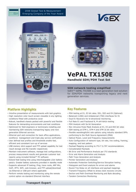
<strong>VePAL</strong> <strong>TX150E</strong><br />
Handheld SDH/PDH Test Set<br />
SDH network testing simplified<br />
VeEX <strong>VePAL</strong> <strong>TX150E</strong> is a next generation test solution<br />
for SDH/PDH networks transporting legacy and next<br />
generation services.<br />
Key Features<br />
▪ PDH testing at E1, E3 bit rates. DS1, DS3 and E4 (Optional)<br />
▪ Balanced (120Ω) and Unbalanced (75Ω) interfaces for E1<br />
▪ Dual E1 Receivers for bi-directional monitoring<br />
▪ Full Rate E1 and Fractional N, M x64 kbit/s testing<br />
▪ PDH Analysis with Sa bit Generation<br />
▪ Non intrusive Pulse Mask Analysis at E1, E3 and DS3 bit rates<br />
▪ SDH testing at STM-1, STM-4 and STM-16 bit rates<br />
▪ Flexible wavelength/bit rate options using industry standard SFPs<br />
conforming to the Multi Source Agreement (MSA)<br />
▪ Optical Power, Level and Frequency measurements<br />
▪ Auto Configuration of network type, bit rate, line coding, framing,<br />
mapping, and test pattern<br />
▪ Payload Mapping according to ITU-T G.707 recommendations<br />
▪ Concatenated Payloads<br />
▪ Bit Error and Performance Analysis per ITU standards<br />
▪ Error and Alarm Generation and Analysis<br />
▪ Path Trace Generation and Analysis<br />
▪ Pointer Generation and Analysis<br />
▪ Automatic Protection Switching/Service Disruption testing<br />
▪ Histogram and Event analysis for errors and alarms<br />
▪ Round Trip Delay on all interfaces and payload mappings<br />
▪ Transmit Frequency Offset to stress clock recovery circuits<br />
▪ Section and Path Overhead Monitoring and Byte decoding<br />
▪ Tandem Connection Monitoring
APPLICATIONS<br />
Installation, commissioning, monitoring and maintenance of SDH and PDH networks simplified thanks to a combination of intuitive features<br />
and powerful test functions. When multiplexing several low order tributaries together, SDH signals are often compromised by various impairments<br />
in the process. Defining the type of anomaly or defect is crucial in isolating the network element or signal path causing the problem<br />
and reducing costly network downtime. Fast troubleshooting and comprehensive analysis of transmission problems can be performed using<br />
intrusive, non-intrusive and monitoring test modes. Novice users will benefit from the easy-to-use Auto-configuration and Tributary Scan<br />
test modes, while experienced users will appreciate the array of advanced features such as Overhead Monitoring and Byte Control, Pointer<br />
Test Sequences, Path Trace generation, Tandem Connection Monitoring and lots more.<br />
Tributary<br />
Signals<br />
VC<br />
Assembly<br />
OUT OF SERVICE TESTING<br />
Applications include;<br />
▪ End-to-end BERT<br />
▪ Tributary Mapping/de-Mapping<br />
▪ Path/Section Trace Generation<br />
▪ Bringing Into Service (M.2100)<br />
▪ Pulse mask analysis (E1/E3/DS3)<br />
▪ Mux Testing<br />
SDH Terminal<br />
Multiplexer<br />
▪ Round Trip Delay (RTD)<br />
Multiplexer<br />
Section<br />
SDH Cross<br />
Connect<br />
Regenerator<br />
Section<br />
Regenerator Regenerator<br />
Path<br />
ADM<br />
Multiplexer<br />
Section<br />
Regenerator<br />
Section<br />
ADM DWDM SDH<br />
ADM<br />
Optical Ring<br />
ADM<br />
Regenerator<br />
Section<br />
SDH Terminal<br />
Multiplexer<br />
Tributary<br />
Signals<br />
VC<br />
Assembly
IN-SERVICE MONITORING<br />
Applications include;<br />
▪ Optical Power and Frequency<br />
▪ Tributary Scanning<br />
▪ Performance Analysis per G.826, G.828, G.829, M.2101<br />
▪ Pointer Analysis and Generation<br />
▪ APS Measurement/Service Disruption<br />
▪ Tandem Connection Monitoring<br />
▪ Overhead Byte Control and Decode<br />
▪ Overhead BERT<br />
PAYLOAD MAPPINGS SUPPORTED<br />
(PER ITU-T G.707 RECOMMENDATIONS)<br />
The SDH Multiplexing principle basically consists of;<br />
▪ Mapping - Tributaries are adapted into Virtual Containers (VCs) by adding<br />
justification bits and Path Overhead (POH)<br />
▪ Aligning - Addition of a Pointer to a Tributary Unit (TU) and Administrative<br />
Unit (AU) for identification of the VC<br />
▪ Multiplexing – Low order path signals are adapted into high order path<br />
signals, or high order signals are multiplexed<br />
The <strong>TX150E</strong> tests the proper operation of Add/Drop Multiplexers, Digital<br />
Cross Connects and other Network Elements (NE) by verifying the mapping<br />
and de-mapping of different tributaries and payloads into SDH containers<br />
and monitors anomalies and defects associated with each process.<br />
The Payload and Path Overhead of each SDH Container (VC) including the<br />
Pointer associated with the PDH tributary can also be monitored. Mapping<br />
of full bandwidth services e.g. IP, Multimedia and ATM is possible using<br />
concatenated payloads.<br />
Pointer<br />
processing<br />
Multiplexing<br />
Mapping<br />
Aligning<br />
x3<br />
x7<br />
x7<br />
x3<br />
TUG-2 TUG-3<br />
x4 x3 x1<br />
TU-11<br />
VC-11<br />
C-11<br />
1.5 Mbit/s<br />
VC-11 Bulk<br />
TU-12<br />
VC-12<br />
STM-1 STM-4 STM-16<br />
x1 x1<br />
x4<br />
x1 x1<br />
AU-3 AU-4 AU-4-4c AU-4-16c<br />
x4<br />
x1<br />
AUG-1 AUG-4 AUG-16<br />
VC-3 VC-4 VC-4-4c VC-4-16c<br />
TU-13<br />
VC-3<br />
C-12 C-3 C-4<br />
2 Mbit/s<br />
VC-12 Bulk<br />
ADM<br />
DWDM SDH<br />
Optical Ring<br />
ADM ADM<br />
ADM<br />
45 Mbit/s<br />
34 Mbit/s<br />
VC-3 Bulk<br />
Protected Monitor Point<br />
(PMP) or Optical Tap<br />
139 Mbit/s<br />
VC-4<br />
VC-4 Bulk<br />
x1<br />
C-4-4c C-4-16c<br />
VC-4-4c Bulk VC-4-16c Bulk
QUICK AND EASY GRAPHICAL SETUP<br />
Encountering a variety of complex daily tasks is common in<br />
today’s network environment, so technicians need a tester that<br />
is easy to configure and which doesn’t require extensive product<br />
training beforehand. Respecting these issues, the test interface,<br />
signal structure, payload mapping and test pattern setup boxes<br />
are structured logically so that the user can quickly and efficiently<br />
configure the unit via an intuitive graphical menu.<br />
A list of shortcuts provides fast access to commonly used SDH or<br />
PDH test functions boosting productivity.<br />
PERFORMANCE ANALYSIS SUMMARY<br />
Performance of each hierarchy is based on byte interleaved parity<br />
(BIP) checksums which are calculated on a frame by frame basis.<br />
These BIP checks are inserted into the Regenerator, Multiplexer<br />
and Path Overhead all of which form an integral part of the performance<br />
monitoring capabilities of an SDH network.<br />
The <strong>TX150E</strong> summary screen quickly shows Pass/Fail criteria for<br />
each performance parameter according to ITU-T recommendations<br />
where applicable.<br />
PHYSICAL LAYER TESTING<br />
Before performing any digital measurements, first confirm that<br />
analog parameters are within prescribed specifications and limits.<br />
Very high optical power levels can saturate or even damage receivers,<br />
while low power levels are susceptible to noise which may in<br />
turn cause bit errors.<br />
Clock frequency offset error is another analog parameter which is<br />
often overlooked. A series of clock tolerances for each signal hierarchy<br />
is clearly defined by ITU-T recommendations and should be<br />
verified as part of any acceptance/conformance test.<br />
ERRORS AND ALARMS<br />
The SDH frame structure contains a large amount of overhead,<br />
some being associated with alarms and in-service monitoring.<br />
Major alarm conditions such as LOS, LOF and LOP cause Alarm Indication<br />
Signals (AIS) to be sent downstream which in turn generate<br />
alarm signals in the upstream direction in a response to AIS<br />
detection.<br />
Anomalies (Errors) and Defects (Alarms) are clearly displayed and<br />
recorded for each network segment by the <strong>TX150E</strong>, and are logged<br />
for further analysis.
SPECIFICATIONS<br />
ELECTRICAL INTERFACES<br />
Dual RJ-48 (120 ohm balanced)<br />
Rates and line code:<br />
▪ 1,544 Mbit/s, AMI & B8ZS (Optional)<br />
▪ 2,048 Mbit/s , HDB3 & AMI<br />
BNC (75 ohm unbalanced)<br />
Rates and line code:<br />
▪ 2,048 Mbit/s, HDB3 & AMI<br />
▪ 34,368 Mbit/s, HDB3<br />
▪ 44,736 Mbit/s, B3ZS (Optional)<br />
▪ 139,264 Mbit/s, CMI (Optional)<br />
▪ 155,520 Mbit/s, CMI (Optional)<br />
Compliant to ITU-T G.703, G.823, G.824, G.825, G.772 and ANSI<br />
T1.102 recommendations where applicable<br />
Clock recovery (pulling range) per ITU-T G.703<br />
Receiver Sensitivity:<br />
For 2.048 Mbit/s (E1);<br />
▪ Terminate: ≤ 6dB (cable loss)<br />
▪ Monitor (PMP): ≤ 26dB (20dB resistive, 6dB cable loss)<br />
▪ Bridge: ≤ 6dB (cable loss)<br />
For 34,368 Mbit/s (E3);<br />
▪ Terminate: ≤ 12dB (cable loss)<br />
▪ Monitor (PMP): ≤ 26dB (20dB resistive, 6dB cable loss)<br />
Optional<br />
For 1.544 Mbit/s (DS1);<br />
▪ Terminate: ≤ 6dB (cable loss)<br />
▪ Monitor (PMP): ≤ 26dB (20dB resistive, 6dB cable loss)<br />
▪ Bridge mode: ≤ 6dB (cable loss)<br />
For 44,736 Mbit/s (DS3);<br />
▪ Terminate: ≤ 6dB (cable loss)<br />
▪ Monitor (PMP): ≤ 26dB (20dB resistive, 6dB cable loss)<br />
SFP optical transceiver selection table (Refer to ordering options)<br />
Receiver Transmitter General<br />
Specifications<br />
For 139,264 Mbit/s (E4) and 155,520 Mbit/s (STM-1E);<br />
▪ Terminate: ≤ 12.7dB (cable loss)<br />
▪ Monitor (PMP): ≤ 26dB (20dB resistive, 6dB cable loss)<br />
CLOCK SYNCHRONIZATION<br />
Internal: 2,048Mbit/s, ± 3.5 ppm stability per ITU-T G.812<br />
Recovered: 2,048 Mbit/s from the incoming signal<br />
External reference via SMA connector<br />
▪ Clock: 2,048 MHz (sine wave or TTL)<br />
▪ Signal: 2,048 Mbit/s (HDB3)<br />
Tx Frequency Offset:<br />
▪ Up to 25,000 ppm in steps of 0.1 ppm for both optical<br />
and electrical interfaces<br />
OPTICAL INTERFACES<br />
Small Form Factor Pluggable (SFP) transceivers compatible with<br />
Multi Source Agreement (MSA)<br />
ROHS compliant and Lead Free per Directive 2002/95/EC<br />
Operating temperature range: -10˚C to 70˚C<br />
Safety: Class 1, per FDA/CDRH, EN (IEC) 60825 eye safety and<br />
EN (IEC) 60950 electrical safety regulations<br />
Compliant to ITU-T G.957 – Optical interfaces and systems<br />
relating to SDH (VeEX supplied SFPs only)<br />
Optical Power Measurement: ± 2dB accuracy, 1dB resolution<br />
(VeEX supplied SFPs only)<br />
Optical option 301-01-004G 301-01-005G 301-01-006G 301-01-007G 301-01-008G 301-01-009G<br />
Wavelength (nm) 1310 1310 1550 1310 1310 1550<br />
Range (km) 15 40 80 15 40 80<br />
Line rate (Mbps) Up to 622 Up to 622 Up to 622 Up to 2488 Up to 2488 Up to 2488<br />
Connector LC duplex LC duplex LC duplex LC duplex LC duplex LC duplex<br />
Line coding NRZ NRZ NRZ NRZ NRZ NRZ<br />
Laser type Fabry Perot DFB DFB DFB DFB DFB<br />
Wavelength range (nm) 1274 to 1356 1280 to 1335 1480 to 1580 1270 to 1360 1280 to 1335 1500 to 1580<br />
Spectral w idth (nm) 2.5 1 1 1 1 1<br />
Output pow er (dBm) -15 to -8 -3 to +2 -3 to +2 -5 to 0 -2 to +3 -2 to +3<br />
Detector type PIN PIN PIN PIN APD APD<br />
Sensitivity (dBm)<br />
@ 155 Mbps<br />
@ 622 Mbps<br />
@ 2.488 Gbps<br />
-28 to -8<br />
-28 to -8<br />
N/A<br />
STM-1/4 (155/622 Mbps)<br />
-28 to -8<br />
-28 to -8<br />
N/A<br />
-28 to -8<br />
-28 to -8<br />
N/A<br />
STM-1/4/16 (155/622/2488 Mbps)<br />
-23 to -10<br />
-22 to 0<br />
-18 to 0<br />
-30 to -15<br />
-29 to -9<br />
-27 to -9<br />
-30 to -15<br />
-29 to -9<br />
-28 to -9<br />
Wavelength range (nm) 1260 to 1600 1260 to 1600 1260 to 1600 1270 to 1600 1270 to 1600 1270 to 1600
SDH FUNCTIONS<br />
OPERATING MODES<br />
Terminated mode<br />
Monitor mode<br />
Intrusive Through mode<br />
▪ Modification of selected SOH bytes<br />
▪ Alarm Generation and Error Insertion of selected defects and<br />
anomalies respectively<br />
Non-Intrusive Through mode<br />
▪ Pass entire signal through without modification of section and<br />
line overhead bytes<br />
SIGNAL STRUCTURE<br />
STM-1 (VC-n container equipped with);<br />
▪ Framed or unframed PDH test pattern (per ITU-T 0.150)<br />
STM-4 (VC-n container equipped with);<br />
▪ Framed or unframed PDH test pattern (per ITU-T 0.150)<br />
▪ Bulk TSS (per ITU-T 0.181)<br />
STM-16 (VC-n container equipped with);<br />
▪ Framed or unframed PDH test pattern (per ITU-T 0.150)<br />
▪ Bulk TSS (per ITU-T 0.181)<br />
MAPPINGS (According to ITU-T G.707)<br />
C-12 (unstructured or framed E1, asynchronous or byte synchronous)<br />
C-3 (unstructured or framed E3 or DS3) via AU-3 or AU-4<br />
C-4 (unstructured or framed E4)<br />
C-4-4c (STM-4 and STM-16)<br />
C-4-16c (STM-16)<br />
Optional<br />
C-11 (unstructured or framed DS1)<br />
PATTERNS<br />
The following test patterns can be generated:<br />
▪ PRBS: 2 11 -1, 2 15 -1, 2 20 -1, 2 23 -1, 2 31 -1: normal or inverted<br />
▪ Fixed: 0000, 1111, 1010, 1000 and 1100<br />
▪ User programmable word: user defined up to 24 bits<br />
ERRORS<br />
Insertion of;<br />
▪ FAS, B1, B2, MS-REI, B3, HP-REI, LP-REI, LP-BIP, slips and<br />
bit errors<br />
Insertion mode:<br />
▪ Single and rate (1 x 10 -3 to 5 x 10 -6 )<br />
Detection of;<br />
▪ FAS, B1, B2, MS-REI, B3, HP-REI, LP-BIP, LP-REI, and bit errors<br />
ALARMS<br />
Generation of;<br />
▪ LOS, LOF, MS-AIS, MS-RDI, RS-TIM, AU-LOP, AU-AIS, HP-UNEQ,<br />
HP-PLM, HP-RDI, HP-TIM, TU-LOM, TU-LOP, TU-AIS, LP-UNEQ,<br />
LP-PLM, LP-RDI, LP-RFI, LP-TIM, 2M AIS, 2M LOF, 2M RDI<br />
Insertion mode: Static (Enable/Disable)<br />
Monitoring and simultaneous detection of;<br />
▪ LOS, LOF, OOF, RS-TIM, MS-AIS, MS-RDI, AU-AIS, AU-LOP, HP-<br />
UNEQ, HP-PLM, HP-TIM, HP-RDI, TU-LOM, TU-AIS, TU-LOP, LP-<br />
UNEQ, LP-PLM, LP-TIM, LP-RDI, LP-RFI<br />
AUTOMATIC CONFIGURATION<br />
Configures tester to the incoming signal – Bit rate, framing, line<br />
coding and test pattern per ITU-T G.707, G.703, 0.151 and 0.181<br />
recommendations where applicable<br />
Transport Expert<br />
OVERHEAD ANALYSIS AND GENERATION<br />
Network Architectures supported<br />
▪ Linear (per G.783) or Ring (per G.841)<br />
Analysis – Decode and display;<br />
SOH/POH bytes in hexadecimal, binary or ASCII formats;<br />
▪ S1 synchronization status<br />
▪ C2 HP signal label<br />
▪ J0 trace identifier (16 bytes) in ASCII format<br />
▪ J1 trace identifier (16 or 64 bytes) in ASCII format<br />
▪ J2 trace identifier (16 or 64 bytes) in ASCII format<br />
▪ K1, K2 APS Control<br />
▪ V5 LP signal label<br />
Generation - Programmable Bytes<br />
RSOH:<br />
▪ J0 trace: 1 byte hexadecimal or 16 byte ASCII sequence<br />
MSOH:<br />
with CRC-7<br />
▪ K1, K2 APS bytes per ITU-T G.783 and G.841<br />
▪ S1 synchronization status message<br />
HO-POH (VC-4, VC-3):<br />
▪ J1 trace: 16 byte ASCII with CRC-7 or 64 byte ASCII sequence<br />
▪ C2 signal label<br />
▪ H4 Sequence / Mutiframe Indicator<br />
▪ G1 (bit 5) – End to end path status (RDI generation)<br />
▪ K3 (bits 1-4) APS signaling<br />
LO-POH (VC-3):<br />
▪ J1 trace: 16 byte ASCII with CRC-7 or 64 byte ASCII sequence<br />
▪ C2 signal label<br />
▪ G1 (bit 5) – End to end path status (RDI generation)<br />
▪ K3 (bits 1-4) APS signaling<br />
LO-POH (VC-12, VC-11):<br />
▪ V5 (bits 5-7) LP signal label<br />
▪ J2 trace: 16 byte ASCII with CRC-7 or 64 byte ASCII sequence<br />
▪ K4 (bits 3-4) LP APS signaling<br />
OVERHEAD BERT:<br />
▪ Generation and analysis of PRBS pattern in DCC channels (D1-D3<br />
or D4-D12 bytes) or E1, E2, F1, N1 and N2 bytes<br />
▪ PRBS: 2 23 -1, 2 20 -1, 2 15 -1, 2 11 -1 (inverted or non inverted)<br />
▪ Bit error counter, rate and errored seconds<br />
POINTER ANALYSIS/GENERATION<br />
Analysis<br />
▪ Current value, Increments, decrements, sum, difference<br />
▪ New Data Flags (NDF)<br />
▪ Tributary frequency offset (ppm of AU/TU)<br />
Generation<br />
▪ Single pointer, increment, decrement, or increment /<br />
decrement<br />
▪ Programming of SS bits<br />
TRIBUTARY SCAN<br />
Automatically scan VC-12s for errors, alarms and events using<br />
sequential BER
PDH FUNCTIONS<br />
OPERATING MODES<br />
Terminated mode<br />
Monitor mode<br />
Intrusive Thru mode (E1 only)<br />
Bridge (E1 only, DS1 Optional)<br />
SIGNAL STRUCTURE<br />
2,048 Mbit/s (E1)<br />
▪ Unframed or Framed with/without CRC per ITU-T G.704<br />
(PCM30, PCM30C, PCM31, PCM31C)<br />
▪ Test signal in N/M x 64 kbit/s where N=1 to 30<br />
34,368 Mbit/s (E3)<br />
▪ Unframed or Framed according to ITU-T G.751<br />
Optional<br />
1,544 Mbit/s (DS1)<br />
▪ Unframed or Framed SF (D4), ESF per ANSI and Telcordia<br />
standards where applicable<br />
▪ Test signal in N x 64 kbit/s, N x 56 kbit/s where N=1 to 24<br />
44,736 Mbit/s (DS3)<br />
▪ Unframed or Framed M13 and C-Bit Parity per ITU-T G.752<br />
or ITU-T G.704<br />
139,264 Mbit/s (E4)<br />
▪ Unframed or Framed according to ITU-T G.751<br />
PATTERNS<br />
The following test patterns can be generated:<br />
▪ PRBS: 2 11 -1, 2 15 -1, 2 20 -1, 2 23 -1, 2 31 -1: normal or inverted<br />
▪ Fixed: 0000, 1111, 1010, 1000 and 1100<br />
▪ User programmable word: user defined up to 24 bits<br />
ERRORS<br />
Insertion;<br />
▪ 2,048 Mbit/s (E1): Code, FAS, CRC, EBIT, Bit errors<br />
▪ 34,368 Mbit/s (E3): Code, FAS, 2M FAS, 2M, Bit errors<br />
▪ Single or continuous rate (1 x 10 -3 to 5 x 10 -6 )<br />
Optional<br />
▪ 1,544 Mbit/s (DS1): Code, FAS, Bit, Frame, CRC<br />
▪ 44,736 Mbit/s (DS3): Code, FAS, MFAS, P/C-Parity, Bit errors<br />
▪ 139,264 Mbit/s (E4): Code, FAS, Bit errors<br />
Measurement:<br />
▪ 2,048 Mbit/s (E1): Code, FAS, CRC, E-BIT and Bit errors<br />
▪ 34,368 Mbit/s (E3): Code, FAS, Bit errors<br />
Optional (DS1, DS3 and E4) – where applicable<br />
▪ Code, FAS, MFAS, 2M CRC, P/C-Parity, Bit errors<br />
ALARMS<br />
Generation:<br />
▪ 2,048 Mbit/s (E1): LOS, AIS, LOF, RDI<br />
▪ 34,368 Mbit/s (E3): LOS, AIS, LOF, RDI, 2M LOF, 2M RDI<br />
▪ Mode: Static (Enable/Disable)<br />
Optional<br />
▪ 1,544 Mbit/s (DS1): AIS, yellow, idle, LOS, LOF<br />
▪ 44,736 Mbit/s (DS3): LOS, LOF, OOF, AIS, Parity<br />
▪ 139,264 Mbit/s (E4): AIS, FAS RDI<br />
Measurement:<br />
▪ 2,048 Mbit/s (E1): LOS, AIS, LOF, LOMF, RDI and LSS<br />
▪ 34,368 Mbit/s (E3): LOS, AIS, LOF, RDI and LSS<br />
Transport Expert<br />
Optional (T-Carrier DS1/DS3)<br />
▪ LOS, AIS, LOF, OOF, IDLE, YELLOW and LSS<br />
MEASUREMENT FUNCTIONS<br />
TEST RESULTS<br />
Error count, ES, %ES, SES, %SES, UAS, %UAS, EFS, %EFS, AS,<br />
%AS, and rate for all events: errors, alarms and pointer events<br />
PERFORMANCE ANALYSIS<br />
Measurements according to:<br />
▪ ITU-T G.821 recommendation: ES, EFS, SES, DM, and UAS with<br />
HRP 1% to 100%<br />
▪ ITU-T G.826 recommendation: EB, BBE, ES, EFS, SES, UAS. HRP<br />
of 1% to 100%.<br />
▪ In service measurement (ISM) using B1, B2, B3, FAS, CRC or<br />
Code (E1).<br />
▪ Out of service measurement (OOS) using bit errors (TSE)<br />
▪ ITU-T G.828 recommendation: ES, EFS, SES, BBE, SEP, UAS with<br />
HRP 1% to 100%<br />
▪ ITU-T G.829 recommendation: ES, EFS, SES, BBE, UAS on RSOH<br />
(B1), MSOH (B2) or TSE<br />
▪ ITU-T M.2100 recommendation: ES, EFS, SES, UAS with HRP 1%<br />
to 100%.<br />
▪ User defined thresholds for Maintenance (MTCE) and Bringing<br />
into Service (BIS) objectives.<br />
▪ ITU-T M.2101 recommendation: ES, EFS, SES, BBE, SEP, UAS<br />
with HRP 1% to 100%.<br />
▪ User defined thresholds for Maintenance (MTCE) and Bringing<br />
into Service (BIS) objectives. In service measurements on both<br />
near and far ends of path using TSE, HP-BIP (B3), MS-BIP (B2),<br />
RS-BIP (B1) and LP-BIP (V5)<br />
COMMON FUNCTIONS AND MEASUREMENTS<br />
AUTO CONFIGURATION<br />
Available on all interfaces:<br />
Identification of received signal - instrument configuration based<br />
on network type, bit rate, line coding, framing, mapping, and test<br />
pattern<br />
FREQUENCY MEASUREMENT<br />
▪ Optical & Electrical Interfaces: Hz & bit/s in ppm<br />
▪ Resolution: 1Hz<br />
▪ TIE measurement on Pointer Justification Events<br />
ROUND TRIP DELAY<br />
Available on all interfaces and mappings:<br />
▪ Measurement Range: 1μS to 10 seconds<br />
▪ Resolution: ±1μs or 1 U.I.<br />
EVENT LOGGING<br />
Date and time stamped events in tabular format<br />
HISTOGRAMS<br />
Available for all interfaces<br />
▪ Display of Errors and Alarms versus time<br />
▪ Resolution: Seconds, minutes, hours and days<br />
LED INDICATORS<br />
▪ Fixed LEDs for Signal, Framing, Pattern and Errors/Alarms<br />
▪ Soft LEDs for SDH/PDH Alarms/Errors displaying historical<br />
events and conditions.
SDH/PDH MEASUREMENT OPTIONS<br />
PULSE MASK ANALYSIS<br />
PDH<br />
▪ Bit rates: 2,048 Mbit/s (E1) and 34,368 Mbit/s (E3)<br />
▪ Mode: Non-Intrusive<br />
▪ Display: Pulse shape with Conformance mask verification<br />
▪ Parameters: Width, Rise/Fall time, Overshoot/Undershoot<br />
▪ Conformance Mask: G.703<br />
T-Carrier<br />
▪ Bit rates: 1,544 Mbit/s (DS1) and 44,736 Mbit/s (DS3)<br />
▪ Conformance Masks: G.703, ANSI T1.102, T1.403, T1.404<br />
where applicable<br />
AUTOMATIC PROTECTION SWITCHING (APS) / SERVICE<br />
DISRUPTION MEASUREMENT<br />
▪ Measurement of disruption time on SDH & PDH interfaces<br />
▪ Tributaries: PDH (E1), SDH<br />
▪ Pass/Fail Range: 1 ms to 10 seconds<br />
▪ Resolution: 1 ms<br />
▪ Triggers: MS-AIS, AU-AIS, TU-AIS, B2<br />
▪ APS Byte (K1/K2) capture and decode<br />
▪ Service Disruption sensor events - LOS, LOF, AIS, TSE<br />
▪ Service Disruption measurements:<br />
▪ Longest, shortest, total and average disruption time<br />
▪ Disruption count<br />
POINTER ANALYSIS/GENERATION<br />
Generation<br />
▪ ITU-T G.783 pointer sequences<br />
TANDEM CONNECTION MONITORING (TCM)<br />
Generation and analysis of N1 and N2 bytes<br />
Errors generated:<br />
▪ TC-IEC, TC-BIP, TC-REI, OEI<br />
Alarms generated:<br />
▪ TC-RDI, TC-UNEQ, TC-LTC, TC-AIS, TC-ODI<br />
Detection, display, analysis and storage of events:<br />
▪ TC-IEC, TC-AIS, TC-REI, TC-RDI, TC-OEI, TC-LTC, TC-UNEQ,<br />
TC-ODI, TC-TIM<br />
▪ Analysis and generation of APId (Access Point Identifier)<br />
General Specifications<br />
Size 210 x 100 x 55 mm (H x W x D)<br />
(8.25 x 3.75 x 2.25 in)<br />
Weight Less than 1 kg (less than 2.2 lbs)<br />
Battery LiIon Battery Pack, Operating time<br />
> 3 hours<br />
AC Adapter Input: 100-240 VAC, 50-60 Hz<br />
Output: 15VDC, 3.5A<br />
Operating Temperature -10˚C to 50˚C (14˚F to 122˚F)<br />
Storage Temperature -20˚C to 70˚C (-4˚F to 158˚F)<br />
Humidity 5% to 95% non-condensing<br />
Display 3.5”QVGA 320x240 full color touch screen<br />
Ruggedness Survives 1m (3 ft) drop to concrete<br />
on all sides<br />
Water-resistance May be used in heavy rain<br />
Interfaces USB 2.0 Host and Client, RJ45<br />
10/100T Ethernet<br />
Languages Multiple languages can be supported<br />
VeEX Inc.<br />
2255, Martin Ave., Suite G,<br />
Santa Clara, CA 95050, USA<br />
Tel: +1.408.970.9090<br />
Fax: +1.408.970.9099<br />
www.veexinc.com<br />
customers@veexinc.com<br />
ORDERING INFORMATION<br />
Z04-00-001P <strong>VePAL</strong> <strong>TX150E</strong> Handheld SDH/PDH Test Set<br />
Interfaces/Test Options<br />
499-05-040 1.544Mbit/s (DS1) and C-11 Mapping<br />
499-05-041 45Mbit/s Testing<br />
499-05-042 155Mbit/s Electrical Testing<br />
499-05-043 155 Mbit/s Optical Testing (require SFP option)<br />
499-05-044 155/622 Mbit/s Optical Testing<br />
(require SFP option)<br />
499-05-045 155/622/2488 Mbit/s Optical Testing<br />
(require SFP option)<br />
499-05-046 APS/Service Disruption Measurement<br />
499-05-047 Tandem Connection Monitoring<br />
499-05-048 ITU-T G.783 Pointer Test Sequences<br />
499-05-049 2 Mbit/s and 34 Mbit/s Pulse Mask Analysis<br />
499-05-050 1.5 Mbit/s Pulse Mask Analysis<br />
499-05-051 45 Mbit/s Pulse Mask Analysis<br />
499-05-052 139 Mbit/s Testing<br />
SFP Transceiver Options<br />
301-01-004G 1310nm IR (15km), 155M/622M STM1/4 -<br />
OC3/12<br />
301-01-005G 1310nm LR (40km), 155M/622M STM1/4 -<br />
OC3/12<br />
301-01-006G 1550nm LR (80km), 155M/622M STM1/4 -<br />
OC3/12<br />
301-01-007G 1310nm IR (15km), 155M/622M/2.5G<br />
STM1/4/16 - OC3/12/48<br />
301-01-008G 1310nm LR (40km), 155M/622M/2.5G<br />
STM1/4/16 - OC3/12/48<br />
301-01-009G 1550nm LR (80km), 155M/622M/2.5G<br />
STM1/4/16 - OC3/12/48<br />
Additional Options<br />
499-05-001 Web Browser (require advanced IP option)<br />
499-05-002 NetWiz<br />
499-05-003 Remote Control<br />
499-05-007 VoIP Expert<br />
499-05-008 IPTV Expert<br />
Z88-00-001G WiFi Wiz, incl. USB WiFi Adaptor<br />
Z88-00-001P VoIP Call Expert, incl. VoIP USB Adaptor &<br />
Earplug<br />
Z88-00-005G Advanced IP, incl. Ethernet Cable<br />
Recommended Accessories<br />
F02-00-008G RJ48 to BNC Test Cable, 2 m<br />
F02-00-009G RJ48 to 3-Pin Banana Test Cable, 2 m<br />
F02-00-010G BNC to BNC Test Cable, 2 m<br />
F05-00-005G LCPC to LCPC Duplex Optical Patchcord, 2 m<br />
F05-00-006G LCPC to SCPC Duplex Optical Patchcord, 2 m<br />
F05-00-007G LCPC to FCPC Duplex Optical Patchcord, 2 m<br />
Replacement Items<br />
405-02-001G Screen Protector<br />
A01-00-001G AC Adaptor<br />
A02-00-001G Car Adaptor<br />
B02-03-001G Battery Pack<br />
C01-00-001G Carrying Case (Basic)<br />
C02-00-002G Carrying Pouch<br />
C03-00-001G Shoulder Strap<br />
F02-00-001G Ethernet Cable RJ45 to RJ45 2 m (6 ft)<br />
F04-00-001G Power Cord - US 2 m (6 ft)<br />
F04-00-002G Power Cord - EU 2 m (6 ft)<br />
F04-00-003G Power Cord - UK 2 m (6 ft)<br />
Z77-00-001G Stylus (pack of 5)<br />
© 2007-2008 VeEX Inc. All rights reserved.<br />
VeEX is a registered trademark of VeEX Inc. The information contained<br />
in this document is accurate. However, we reserve the right to change<br />
any contents at any time without notice. We accept no responsibility for<br />
any errors or omissions. In case of discrepancy, the web version takes<br />
precedence over any printed literature.<br />
D05-00-016P B00 2008/05


