Rxf - Johnson Controls Inc.
Rxf - Johnson Controls Inc.
Rxf - Johnson Controls Inc.

Create successful ePaper yourself
Turn your PDF publications into a flip-book with our unique Google optimized e-Paper software.
NOTE: Care must be taken when entering the unit to<br />
ensure that the nitrogen charge is safely released.<br />
Holding charge shipping gauges on<br />
separator and external oil cooler are<br />
rated for 30 PSIG and are for checking<br />
the shipping charge only. They must be removed<br />
before pressure testing the system and before charging<br />
the system with refrigerant. Failure to remove these<br />
gauges may result in catastrophic failure of the gauge and<br />
uncontrolled release of refrigerant resulting in serious<br />
injury or death.<br />
All units must be kept in a clean, dry location to prevent<br />
corrosion damage. Reasonable consideration must be given<br />
to proper care for the solid-state components of the microprocessor.<br />
Units which will be stored for more than two months must<br />
have the nitrogen charge checked periodically. Contact<br />
<strong>Johnson</strong> <strong>Controls</strong>-Frick for long term storage procedure.<br />
COMPRESSOR OIL<br />
DO NOT MIX OILS of different<br />
brands, manufacturers, or types.<br />
Mixing of oils may cause excessive<br />
oil foaming, nuisance oil level cutouts, oil pressure loss,<br />
gas or oil leakage and catastrophic compressor failure.<br />
NOTE: The oil charge shipped with the unit is the best<br />
suited lubricant for the conditions specified at the time<br />
of purchase. If there is any doubt due to the refrigerant,<br />
operating pressures, or temperatures; refer to Frick publication<br />
160-802 SPC for guidance.<br />
OIL CHARGE<br />
The normal charging level is midway in the top sight<br />
glass located midway along the oil separator shell. Normal<br />
operat ing level is between the top sight glass and bottom<br />
sight glass. Oil charge quantities are as follows:<br />
BASIC ADDITIONAL FOR<br />
RXF CHARGE OIL COOLER<br />
MODEL (gallon) (gallon)<br />
12 – 19 10 1<br />
24 – 50 11 1<br />
58, 68 25 3½<br />
85, 101 36 3½<br />
Add oil by attaching the end of a suitable pressure type<br />
hose to the oil drain valve, located under the oil separator.<br />
Using a pressure-type pump and the recommended Frick ®<br />
oil, open the drain valve and pump oil into the separator.<br />
NOTE: Evacuation of the oil separator will assist the flow<br />
of oil into the unit. Also, fill slowly because oil will fill up<br />
in the separator faster than it shows in the sight glass.<br />
Oil distillers and similar equipment which trap oil must be<br />
filled prior to unit operation to normal design outlet levels.<br />
The same pump used to charge the unit may be used for<br />
filling these auxiliary oil reservoirs.<br />
The sight glass located near the bottom of the separator shell<br />
at the discharge end should remain empty when the unit is<br />
in operation. The presence of oil in this end of the vessel<br />
during operation indicates liquid carryover or malfunc tion<br />
of the oil return.<br />
RXF ROTARY SCREW COMPRESSOR UNITS<br />
INSTALLATION<br />
OIL HEATER<br />
070.410-IOM (JUL 11)<br />
Page 7<br />
Standard units are equipped with 500 watt oil heaters, which<br />
provide sufficient heat to maintain the oil tempera ture for<br />
most indoor applications during shutdown cycles and to<br />
permit safe start-up. RXF 12–50 use one heater while models<br />
58–101 use two. Should additional heating capacity be<br />
required because of an unusual environmental condition,<br />
contact <strong>Johnson</strong> <strong>Controls</strong>-Frick. The heater is energized only<br />
when the unit is not in operation.<br />
Do not energize the heater when there<br />
is no oil in the unit, otherwise the<br />
heater will burn out. The oil heater<br />
will be energized whenever 120 volt control power is applied<br />
to the unit and the compressor is not running, unless the<br />
16 amp circuit breaker in micro enclosure is turned off (or<br />
15 amp fuse (1FU) in the Plus panel is removed).<br />
OIL FILTER(S)<br />
Use of filter elements other than<br />
Frick may cause warranty claim to<br />
be denied.<br />
The oil filter(s) and coalescer filter element(s) shipped with<br />
the unit are best suited to ensure proper filtration and operation<br />
of the system.<br />
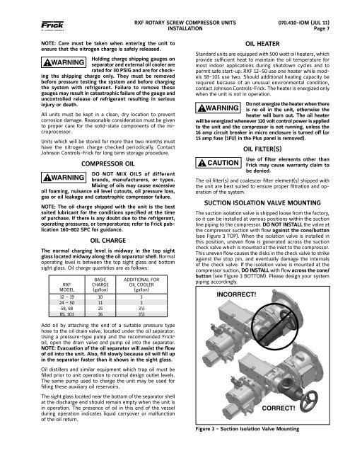
SUCTION ISOLATION VALVE MOUNTING<br />
The suction isolation valve is shipped loose from the factory,<br />
so it can be installed at various positions within the suction<br />
line piping to the compressor. DO NOT INSTALL the valve at<br />
the compressor suction with flow against the cone/button<br />
(see Figure 3 TOP). When the isolation valve is installed in<br />
this position, uneven flow is generated across the suction<br />
check valve which is mounted at the inlet to the compressor.<br />
This uneven flow causes the disks in the check valve to strike<br />
against the stop pin, and eventually damage the internals<br />
of the check valve. If the isolation valve is mounted at the<br />
compressor suction, DO INSTALL with flow across the cone/<br />
button (see Figure 3 BOTTOM). Please design your system<br />
piping accordingly.<br />
INCORRECT!<br />
CORRECT!<br />
Figure 3 - Suction Isolation Valve Mounting


![[PDF] Intelligent Fire Annunciator IFA-1000 - Johnson Controls Inc.](https://img.yumpu.com/7424420/1/190x245/pdf-intelligent-fire-annunciator-ifa-1000-johnson-controls-inc.jpg?quality=85)