Rxf - Johnson Controls Inc.
Rxf - Johnson Controls Inc.
Rxf - Johnson Controls Inc.

You also want an ePaper? Increase the reach of your titles
YUMPU automatically turns print PDFs into web optimized ePapers that Google loves.
Installation<br />
FOUNDATION<br />
NOTE: Allow space for servicing both ends of the unit. A<br />
minimum of 24 inches is recommended.<br />
The first requirement of the compressor foundation is that<br />
it must be able to support the weight of the compressor<br />
package including coolers, oil, and refrigerant charge. Screw<br />
compressors are capable of converting large quantities of<br />
shaft power into gas compression in a relatively small space<br />
and a mass is required to effectively dampen these relatively<br />
high frequency vibrations.<br />
Firmly anchoring the compressor package to a suitable<br />
foundation by proper application of grout and elimination of<br />
piping stress imposed on the compressor is the best insurance<br />
for a trouble free installation. Use only the certified<br />
general arrangement drawings from Frick ® to determine the<br />
mounting foot locations and to allow for recommended clearances<br />
around the unit for ease of operation and servicing.<br />
Foundations must be in compliance with local building codes<br />
and materials should be of industrial quality.<br />
The floor shall be a minimum of 6 inches of reinforced concrete<br />
and housekeeping pads are recommended. Anchor<br />
bolts are required to firmly tie the unit to the floor. Once the<br />
unit is rigged into place (See HANDLING and MOVING), the<br />
feet must then be shimmed in order to level the unit. The<br />
shims should be placed to position the feet roughly one inch<br />
above the housekeeping pad to allow room for grouting. An<br />
expansion-type epoxy grout must be worked under all areas<br />
of the base with no voids and be allowed to settle with a<br />
slight outward slope so oil and water can run off of the base.<br />
When installing on a steel base, the following guidelines<br />
should be implemented to properly design the system base:<br />
1. Use I-beams in the skid where the screw compressor will<br />
be attached to the system base. They shall run parallel to<br />
the package feet and support the feet for their full length.<br />
2. The compressor unit feet shall be continuously welded to<br />
the system base at all points of contact.<br />
3. The compressor unit shall not be mounted on vibration<br />
isolators in order to hold down package vibration levels.<br />
4. The customer’s foundation for the system base shall fully<br />
support the system base under all areas, but most certainly<br />
under the I-beams that support the compressor package.<br />
When installing on the upper floors of buildings, extra precautions<br />
should be taken to prevent normal package vibration<br />
from being transferred to the building structure. It may be<br />
necessary to use rubber or spring isolators, or a combination<br />
of both, to prevent the transmission of compressor vibration<br />
directly to the structure. However, this may increase package<br />
vibration levels because the compressor is not in contact with<br />
any damping mass. The mounting and support of suction<br />
and discharge lines is also very important. Rubber or spring<br />
pipe supports may be required to avoid exciting the building<br />
structure at any pipe supports close to the compressor<br />
package. It is best to employ a vibration expert in the design<br />
of a proper mounting arrangement.<br />
In any screw compressor installation, suction and discharge<br />
lines shall be supported in pipe hangers (preferably within<br />
2 feet of vertical pipe run) so that the lines won’t move if<br />
disconnected from the compressor. See table for Allowable<br />
Flange Loads.<br />
RXF ROTARY SCREW COMPRESSOR UNITS<br />
INSTALLATION<br />
070.410-IOM (JUL 11)<br />
Page 5<br />
ALLOWABLE fLANGE LOADS<br />
NOZ. MOMENTS (ft-lbf) LOAD (lbf)<br />
SIZE AXIAL VERT. LAT. AXIAL VERT. LAT.<br />
NpS MR MC ML p VC VL<br />
1 25 25 25 50 50 50<br />
1.25 25 25 25 50 50 50<br />
1.5 50 40 40 100 75 75<br />
2 100 70 70 150 125 125<br />
3 250 175 175 225 250 250<br />
4 400 200 200 300 400 400<br />
5 425 400 400 400 450 450<br />
6 1,000 750 750 650 650 650<br />
8 1,500 1,000 1,000 1,500 900 900<br />
10 1,500 1,200 1,200 1,500 1,200 1,200<br />
12 1,500 1,500 1,500 1,500 1,500 1,500<br />
14 2,000 1,800 1,800 1,700 2,000 2,000<br />
Proper foundations and proper installation methods are vital;<br />
and even then, sound attenuation or noise curtains may be<br />
required to reduce noise to desired levels.<br />
For more detailed information on Screw Compressor Foundations,<br />
please request Frick publication S70-210 IB.<br />
HANDLING and MOVING<br />
This screw compressor package may<br />
be top-heavy. Use caution in rigging<br />
and handling.<br />
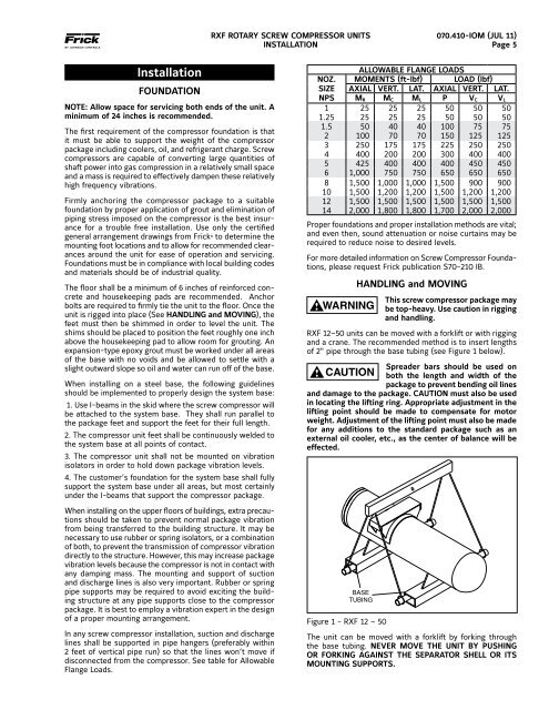
RXF 12–50 units can be moved with a forklift or with rigging<br />
and a crane. The recommended method is to insert lengths<br />
of 2" pipe through the base tubing (see Figure 1 below).<br />
Spreader bars should be used on<br />
both the length and width of the<br />
package to prevent bending oil lines<br />
and damage to the package. CAUTION must also be used<br />
in locating the lifting ring. Appropriate adjust ment in the<br />
lifting point should be made to compensate for motor<br />
weight. Adjustment of the lifting point must also be made<br />
for any additions to the standard package such as an<br />
external oil cooler, etc., as the center of balance will be<br />
effected.<br />
Figure 1 - RXF 12 – 50<br />
The unit can be moved with a forklift by forking through<br />
the base tubing. NEVER MOVE THE UNIT BY PUSHING<br />
OR FORKING AGAINST THE SEPARATOR SHELL OR ITS<br />
MOUNT ING SUPPORTS.


![[PDF] Intelligent Fire Annunciator IFA-1000 - Johnson Controls Inc.](https://img.yumpu.com/7424420/1/190x245/pdf-intelligent-fire-annunciator-ifa-1000-johnson-controls-inc.jpg?quality=85)