Rxf - Johnson Controls Inc.
Rxf - Johnson Controls Inc.
Rxf - Johnson Controls Inc.

You also want an ePaper? Increase the reach of your titles
YUMPU automatically turns print PDFs into web optimized ePapers that Google loves.
070.410-IOM (JUL 11)<br />
Page 26<br />
DEMAND PUMP DISASSEMBLY<br />
RXF ROTARY SCREW COMPRESSOR UNITS<br />
MAINTENANCE<br />
BEFORE OPENING ANY VIKING PUMP<br />
LIQUID CHAMBER (PUMPING CHAM-<br />
BER, RESERVOIR, JACKET, ETC.)<br />
ENSURE:<br />
1. THAT ANY PRESSURE IN THE CHAMBER HAS BEEN<br />
COMPLETELY VENTED THROUGH SUCTION OR DISCHARGE<br />
LINES OR OTHER APPROPRIATE OPENINGS OR CONNEC-<br />
TIONS.<br />
2. THAT THE DRIVING MEANS (MOTOR, TURBINE, EN-<br />
GINE, ETC.) HAS BEEN “LOCKED OUT” OR MADE NON-<br />
OPERATIONAL SO THAT IT CANNOT BE STARTED WHILE<br />
WORK IS BEING DONE ON THE PUMP.<br />
FAILURE TO FOLLOW ABOVE LISTED PRECAUTIONARY<br />
MEASURES MAY RESULT IN SERIOUS INJURY OR DEATH.<br />
1. Mark head and casing before disassembly to ensure proper<br />
reassembly. The idler pin, which is offset in the pump head,<br />
must be positioned up and equal distance between port connections<br />
to allow for proper flow of liquid through the pump.<br />
2. Remove the head capscrews.<br />
3. Tilt top of head back when removing to prevent idler from<br />
falling off idler pin.<br />
4. Remove idler and bushing assembly. If idler bushing needs<br />
replacing, see INSTALLATION OF CARBON GRAPHITE<br />
BUSHINGS.<br />
5. Insert a brass bar or piece of hardwood in the port opening<br />
and between the rotor teeth to keep the shaft from turning.<br />
Turn the locknut counterclockwise and remove locknut. See<br />
Figure 29 or 30.<br />
6. Loosen the two setscrews in the face of bearing housing<br />
and turn the thrust bearing assembly counterclockwise and<br />
remove from casing. See Figure 29 or 30.<br />
7. GG, HJ, HL: Remove the snap ring from the shaft. See<br />
Figure 29. AS, AK, AL: Remove the bearing spacer from the<br />
shaft. See Figure 30.<br />
8. Remove the brass bar or piece of hardwood from the<br />
port opening.<br />
9. The rotor and shaft can now be removed by tapping on<br />
the end of the shaft with a lead hammer or, if using a regular<br />
hammer, use a piece of hardwood between the shaft and<br />
hammer. The rotary member of the seal will come out with<br />
the rotor and shaft.<br />
10. AS, AK, AL: Remove the bearing retainer washer. The<br />
washer may have stayed with rotor and shaft when removed<br />
or is against ball bearing. See Figure 30.<br />
11. Remove the mechanical seal rotary member and spring<br />
from the rotor and shaft assembly.<br />
12. GG, HJ, HL: Remove inner snap ring and single-row ball<br />
bearing from the casing.<br />
AS, AK, AL: Remove single-row ball bearing from casing.<br />
13. Remove seal seat or stationary part of seal from casing.<br />
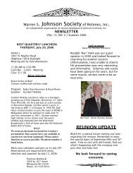
14. Disassemble the thrust-bearing assembly.<br />
GG, HJ, HL: Remove outer snap ring from the bearing hous ing<br />
and remove the ball bearing. See Figure 29.<br />
AS, AK, AL: Loosen the two set screws in flange outside<br />
diameter. Rotate end cap and lip seal counterclockwise and<br />
remove. Remove the ball bearing. See Figure 30.<br />
The casing should be examined for wear, particularly in the<br />
area between ports. All parts should be checked for wear<br />
before the pump is put together.<br />
When making major repairs, such as replacing a rotor and<br />
shaft, it is advisable to also install a new mechanical seal,<br />
head and idler pin, idler, and bushing. See INSTALLATION<br />
OF CARBON-GRAPHITE BUSHINGS.<br />
Clean all parts thoroughly and examine for wear or damage.<br />
Check lip seals, ball bearings, bushing, and idler pin and<br />
replace if necessary. Check all other parts for nicks, burrs,<br />
excessive wear and replace if necessary.<br />
Wash bearings in clean solvent. Blow out bearings with<br />
compressed air. Do not allow bearings to spin; turn them<br />
slowly by hand. Spinning bearings will damage the race<br />
and balls. Make sure bearings are clean, then lubricate with<br />
refrigeration oil and check for roughness. Roughness can<br />
be determined by turning outer race by hand. Replace the<br />
bearings if they have roughness.<br />
Be sure shaft is free from nicks, burrs and foreign particles<br />
that might damage mechanical seal. Scratches on shaft in<br />
seal area will provide leakage paths under mechanical seal.<br />
Use fine emery cloth to remove scratches or sharp edges.<br />
Figure 29 - Thrust-Bearing assembly (gg, HJ, HL) Figure 30 - Thrust-Bearing assembly (AS, AK, AL)


![[PDF] Intelligent Fire Annunciator IFA-1000 - Johnson Controls Inc.](https://img.yumpu.com/7424420/1/190x245/pdf-intelligent-fire-annunciator-ifa-1000-johnson-controls-inc.jpg?quality=85)