Rxf - Johnson Controls Inc.
Rxf - Johnson Controls Inc. Rxf - Johnson Controls Inc.
070.410-IOM (JUL 11) Page 14 tion pressure before it fully powers open. The heavier spring is not required because booster compressors are equipped with a demand oil pump. The RXF package is also equipped with a suction check valve bypass. The oil separator will slowly bleed down to system suction pressure when the unit is stopped. This allows the compressor drive motor to have an easier start, and the discharge check valve will seat more tightly. See the "SUCTION CHECK VALVE BYPASS" section for operation. Figure 15 DEMAND PUMP OIL SYSTEM This system is designed to provide adequate compressor lubrication for some high stage applications that operate with low differential pressure across the compressor suction and discharge and all booster applications. On start-up, Quantum LX will calculate the pressure differential between the compressor discharge and the main oil injection port. If this differential is less than 35 psi, then the demand pump will turn on and will continue to run until 45 psi differential is obtained. Then, the pump will shut down and start only when the differential pressure falls below 35 psi. NOTE: For alarm descriptions and shutdown or cutout parameters, see publication 090-020 O. COMPRESSOR OIL SEPARATION SYSTEM The RXF is an oil-flooded screw compressor. Most of the oil discharged by the compressor separates from the gas flow in the oil charge reservoir. Some oil, however, is discharged as a mist which does not separate readily from the gas flow and is carried past the oil charge reser voir. The coalescer filter element then coalesces the oil mist into droplets, the droplets of oil fall to the bottom of the coalescer section of the oil separator. The return of this oil to the compressor is controlled by a hand expansion valve (HV1). See Figure 16. NOTE: Open HV1 only enough to keep the coalescer end of the separator free of oil. The sight glass located near the bottom of the coales cer section of the oil separator should remain empty during normal operation. If an oil level develops and remains in the sight glass, a problem in the oil return separation system or RXF ROTARY SCREW COMPRESSOR UNITS OPERATION Figure 16 SEPARATOR DISCHARGE COALESCER FROM OIL OUTLET COMPRESSOR SUCTION OIL RESERVOIR COMPR DISCHARGE OIL OUTLET compressor operation has develop ed. Refer to Maintenance for information on how to correct the problem. NOTE: Normal operat ing level is between the top sight glass and bottom sight glass located midway along the oil separator shell. COMPRESSOR HYDRAULIC SYSTEM The hydraulic system of the RXF compressor utilizes oil pressure from internally drilled passages in the compressor casing to selectively load and unload the compressor by applying this pressure to the actuating hydraulic piston of the movable slide valve (MSV). It also uses oil pressure to actuate a hydraulic piston that moves the movable slide stop, Volumizer ® II. This allows adjustment of the compressor volume ratio, (Vi) while the compressor is running. CAPACITY CONTROL COMPRESSOR LOADING: The compressor loads when MSV solenoid coil YY2 is energized and oil flows from the solenoid valve through the needle valve (HV2) to compressor port 2, where it enters the load side of the slide valve piston. This equalizes the force on the slide valve piston and discharge pressure on the slide valve area loads the compressor. See Figure 17. Figure 17 STR HV-1
COMPRESSOR UNLOADING: The compressor unloads when MSV solenoid YY1 is energized and oil is allowed to flow from compressor port 2 thru the needle valve to the MSV solenoid. This allows discharge pressure on the slide valve piston to unload the slide valve as the piston moves outward. ADJUSTMENT (Capacity Control): A needle valve (HV2) is provided to adjust slide valve travel time, preventing excessive slide valve “hunting”. HV2 should be adjusted to restrict oil flow to the compressor port so that slide valve travel time from full load to full unload, or vice versa, is a minimum of 30 seconds. NOTE: A change in operating conditions, such as winterto-summer operation, may require readjustment of slide valve travel time. VOLUMIZER ® II Vi CONTROL The RXF compressor is equipped with a special internal control that automatically adjusts the compressor volume ratio to the most efficient of three available steps, (2.2, 3.5, or 5.0 volume ratio). This gives the compressor the ability to operate at varying operating conditions while minimizing power consumption by avoiding over or undercompression. Solenoid valves 3 and 4 (See Figures 18 - 20 and location on P & I diagram represented by YY3 and YY4) control the Volumizer ® II volume ratio control. Oil is internally ported to apply hydraulic pressure to two stepping pistons in order to move the moveable slide stop to the optimum position. The following chart shows the logic of solenoid operation to adjust the volume ratio. Vi SOLENOID 3 / YY3 SOLENOID 4 / YY4 2.2 Energized Energized 3.5 Deenergized Energized 5.0 Deenergized Deenergized Proper operation of the Volumizer ® II control can be checked as follows. 1. Confirm that the slide valve travel number in Factory Setup is set at 190 degrees. If necessary, adjust the setting to 190 degrees before proceeding further. 2. Set the compressor Vi to 2.2, then record the voltage that is shown on the Slide Valve calibration screen for the current Slide Valve and 0% Slide Valve positions. The difference between these voltages must be in the 1.35 - 1.65 Vdc range. 3. Set the compressor Vi to 3.5, then record the voltage that is shown on the Slide Valve calibration screen for the current Slide Valve and 0% Slide Valve positions. The difference between these voltages must be in the 0.95 - 1.15 Vdc range. 4. Set the compressor Vi to 5.0, then record the voltage that is shown on the Slide Valve calibration screen for the current Slide Valve and 0% Slide Valve positions. The difference between these voltages must be in the 0.73 - 0.93 Vdc range. 5. If the above voltage measurements are all in range, the Volumizer ® II is working properly. If any of the voltages are out of range, go to the troubleshooting section. Proper installation of the Vi control valves and gaskets is essential to the operation of this equipment. Incorrectly installed parts may cause the compressor to operate at the wrong Vi, or to load or unload improperly. Operation at the wrong compressor Vi can cause excessive power consumption, noise, vibration, or excessive oil foaming. See Figures RXF ROTARY SCREW COMPRESSOR UNITS OPERATION 070.410-IOM (JUL 11) Page 15 18 - 20 for correct installation of gaskets and location of solenoids. COMMON VENT PRESSURE PRESSURE COMMON YY4 OUT OUT YY3 GASKET INSTALLATION SIDE VIEW Figure 18 - RXF 12–19 Vi Control Figure 19 - RXF 24–50 Vi Control Figure 20 - RXF 58–101 Vi Control SLIDE VALVE CALIBRATION Slide valve calibration is performed on the QuantumLX control panel in automatic mode. If further problems occur or persist, contact Johnson Controls-Frick service.
- Page 1 and 2: Form 070.410-IOM (JUL 2011) RXF ROT
- Page 3 and 4: PREFACE This manual has been prepar
- Page 5 and 6: Installation FOUNDATION NOTE: Allow
- Page 7 and 8: NOTE: Care must be taken when enter
- Page 9 and 10: 4. Welding should occur in two segm
- Page 11 and 12: Other than the isolation valve need
- Page 13: Operation OPERATION and START-UP IN
- Page 17 and 18: • Use the [ 0 ] key to change the
- Page 19 and 20: • Alarms - If an alarm has been d
- Page 21 and 22: THERMOSYPHON OIL COOLING Thermosyph
- Page 23 and 24: etween the separator shell and comp
- Page 25 and 26: When changing the coalescer filter
- Page 27 and 28: DEMAND PUMP ASSEMBLY Assembly Notes
- Page 29 and 30: Pressure gauge - Discharge Port 1.
- Page 31 and 32: Figure 33 MOTOR BEARINGS Lubricate
- Page 33 and 34: an allowance in the readings must b
- Page 35 and 36: RXF ROTARY SCREW COMPRESSOR UNITS M
- Page 37 and 38: RXF ROTARY SCREW COMPRESSOR UNITS M
- Page 39 and 40: RXF ROTARY SCREW COMPRESSOR UNITS M
- Page 41 and 42: LIQUID REFRIGERANT FROM RECEIVER CO
- Page 43 and 44: CONNECTIONS 1 MAIN OIL SUPPLY 2 SLI
- Page 45 and 46: RXF ROTARY SCREW COMPRESSOR UNITS M
- Page 47 and 48: RXF ROTARY SCREW COMPRESSOR UNITS M
- Page 49 and 50: GROUNDING Grounding is the most imp
- Page 51 and 52: Drilling can cause metal filings to
- Page 53 and 54: FORMS RXF ROTARY SCREW COMPRESSOR U
- Page 55 and 56: RXF ROTARY SCREW COMPRESSOR UNITS F
- Page 57 and 58: RXF ROTARY SCREW COMPRESSOR UNITS F
- Page 59 and 60: RXF ROTARY SCREW COMPRESSOR UNITS F
- Page 61 and 62: Heat-sink paste, 8 high-stage opera
- Page 63 and 64: RXF ROTARY SCREW COMPRESSOR UNITS N
070.410-IOM (JUL 11)<br />
Page 14<br />
tion pressure before it fully powers open. The heavier spring<br />
is not required because booster compressors are equipped<br />
with a demand oil pump.<br />
The RXF package is also equipped with a suction check valve<br />
bypass. The oil separator will slowly bleed down to system<br />
suction pressure when the unit is stopped. This allows the<br />
compressor drive motor to have an easier start, and the discharge<br />
check valve will seat more tightly. See the "SUCTION<br />
CHECK VALVE BYPASS" section for operation.<br />
Figure 15<br />
DEMAND PUMP OIL SYSTEM<br />
This system is designed to provide adequate compressor<br />
lubrication for some high stage applications that operate<br />
with low differential pressure across the compressor suction<br />
and discharge and all booster applications.<br />
On start-up, Quantum LX will calculate the pressure differential<br />
between the compressor discharge and the main oil<br />
injection port. If this differential is less than 35 psi, then the<br />
demand pump will turn on and will continue to run until 45 psi<br />
differential is obtained. Then, the pump will shut down and<br />
start only when the differential pressure falls below 35 psi.<br />
NOTE: For alarm descriptions and shutdown or cutout<br />
parameters, see publication 090-020 O.<br />
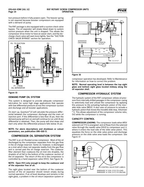
COMPRESSOR OIL SEPARATION SYSTEM<br />
The RXF is an oil-flooded screw compressor. Most of the oil<br />
discharged by the compressor separates from the gas flow<br />
in the oil charge reservoir. Some oil, however, is discharged<br />
as a mist which does not separate readily from the gas flow<br />
and is carried past the oil charge reser voir. The coalescer<br />
filter element then coalesces the oil mist into droplets, the<br />
droplets of oil fall to the bottom of the coalescer section of<br />
the oil separator. The return of this oil to the compressor is<br />
controlled by a hand expansion valve (HV1). See Figure 16.<br />
NOTE: Open HV1 only enough to keep the coalescer end<br />
of the separator free of oil.<br />
The sight glass located near the bottom of the coales cer<br />
section of the oil separator should remain empty during<br />
normal operation. If an oil level develops and remains in the<br />
sight glass, a problem in the oil return separation system or<br />
RXF ROTARY SCREW COMPRESSOR UNITS<br />
OPERATION<br />
Figure 16<br />
SEPARATOR<br />
DISCHARGE<br />
COALESCER<br />
FROM OIL<br />
OUTLET<br />
COMPRESSOR<br />
SUCTION<br />
OIL RESERVOIR<br />
COMPR<br />
DISCHARGE<br />
OIL OUTLET<br />
compressor operation has develop ed. Refer to Maintenance<br />
for information on how to correct the problem.<br />
NOTE: Normal operat ing level is between the top sight<br />
glass and bottom sight glass located midway along the<br />
oil separator shell.<br />
COMPRESSOR HYDRAULIC SYSTEM<br />
The hydraulic system of the RXF compressor utilizes oil pressure<br />
from internally drilled passages in the compressor casing<br />
to selectively load and unload the compressor by applying<br />
this pressure to the actuating hydraulic piston of the movable<br />
slide valve (MSV). It also uses oil pressure to actuate a<br />
hydraulic piston that moves the movable slide stop, Volumizer<br />
® II. This allows adjustment of the compressor volume ratio,<br />
(Vi) while the compressor is running.<br />
CAPACITY CONTROL<br />
COMPRESSOR LOADING: The compressor loads when MSV<br />
solenoid coil YY2 is energized and oil flows from the solenoid<br />
valve through the needle valve (HV2) to compressor port 2,<br />
where it enters the load side of the slide valve piston. This<br />
equalizes the force on the slide valve piston and discharge<br />
pressure on the slide valve area loads the compressor. See<br />
Figure 17.<br />
Figure 17<br />
STR<br />
HV-1


